EP4318889A1 - Coil for motor, method for manufacturing coil for motor, and motor - Google Patents
Coil for motor, method for manufacturing coil for motor, and motor Download PDFInfo
- Publication number
- EP4318889A1 EP4318889A1 EP22779597.8A EP22779597A EP4318889A1 EP 4318889 A1 EP4318889 A1 EP 4318889A1 EP 22779597 A EP22779597 A EP 22779597A EP 4318889 A1 EP4318889 A1 EP 4318889A1
- Authority
- EP
- European Patent Office
- Prior art keywords
- portions
- coil
- primary
- axis
- another
- Prior art date
- Legal status (The legal status is an assumption and is not a legal conclusion. Google has not performed a legal analysis and makes no representation as to the accuracy of the status listed.)
- Pending
Links
- 238000004519 manufacturing process Methods 0.000 title claims description 19
- 238000000034 method Methods 0.000 title claims description 19
- 238000001816 cooling Methods 0.000 claims abstract description 77
- 239000004020 conductor Substances 0.000 claims abstract description 13
- 238000004804 winding Methods 0.000 claims abstract description 13
- 230000002093 peripheral effect Effects 0.000 claims description 65
- 238000009423 ventilation Methods 0.000 claims description 18
- 239000000654 additive Substances 0.000 claims description 6
- 230000000996 additive effect Effects 0.000 claims description 6
- 230000000149 penetrating effect Effects 0.000 claims description 4
- 230000003247 decreasing effect Effects 0.000 description 7
- 238000007664 blowing Methods 0.000 description 4
- 239000011347 resin Substances 0.000 description 3
- 229920005989 resin Polymers 0.000 description 3
- 230000000694 effects Effects 0.000 description 2
- 239000010408 film Substances 0.000 description 2
- 239000002184 metal Substances 0.000 description 2
- 210000003298 dental enamel Anatomy 0.000 description 1
- 238000010586 diagram Methods 0.000 description 1
- 230000020169 heat generation Effects 0.000 description 1
- 230000003993 interaction Effects 0.000 description 1
- 238000012986 modification Methods 0.000 description 1
- 230000004048 modification Effects 0.000 description 1
- 239000000843 powder Substances 0.000 description 1
- 239000010409 thin film Substances 0.000 description 1
Images



Classifications
-
- H—ELECTRICITY
- H02—GENERATION; CONVERSION OR DISTRIBUTION OF ELECTRIC POWER
- H02K—DYNAMO-ELECTRIC MACHINES
- H02K9/00—Arrangements for cooling or ventilating
- H02K9/02—Arrangements for cooling or ventilating by ambient air flowing through the machine
-
- H—ELECTRICITY
- H02—GENERATION; CONVERSION OR DISTRIBUTION OF ELECTRIC POWER
- H02K—DYNAMO-ELECTRIC MACHINES
- H02K15/00—Processes or apparatus specially adapted for manufacturing, assembling, maintaining or repairing of dynamo-electric machines
- H02K15/02—Processes or apparatus specially adapted for manufacturing, assembling, maintaining or repairing of dynamo-electric machines of stator or rotor bodies
- H02K15/021—Magnetic cores
- H02K15/026—Wound cores
-
- H—ELECTRICITY
- H02—GENERATION; CONVERSION OR DISTRIBUTION OF ELECTRIC POWER
- H02K—DYNAMO-ELECTRIC MACHINES
- H02K15/00—Processes or apparatus specially adapted for manufacturing, assembling, maintaining or repairing of dynamo-electric machines
- H02K15/04—Processes or apparatus specially adapted for manufacturing, assembling, maintaining or repairing of dynamo-electric machines of windings prior to their mounting into the machines
-
- H—ELECTRICITY
- H02—GENERATION; CONVERSION OR DISTRIBUTION OF ELECTRIC POWER
- H02K—DYNAMO-ELECTRIC MACHINES
- H02K15/00—Processes or apparatus specially adapted for manufacturing, assembling, maintaining or repairing of dynamo-electric machines
- H02K15/06—Embedding prefabricated windings in the machines
-
- H—ELECTRICITY
- H02—GENERATION; CONVERSION OR DISTRIBUTION OF ELECTRIC POWER
- H02K—DYNAMO-ELECTRIC MACHINES
- H02K3/00—Details of windings
- H02K3/04—Windings characterised by the conductor shape, form or construction, e.g. with bar conductors
- H02K3/24—Windings characterised by the conductor shape, form or construction, e.g. with bar conductors with channels or ducts for cooling medium between the conductors
-
- H—ELECTRICITY
- H02—GENERATION; CONVERSION OR DISTRIBUTION OF ELECTRIC POWER
- H02K—DYNAMO-ELECTRIC MACHINES
- H02K9/00—Arrangements for cooling or ventilating
- H02K9/22—Arrangements for cooling or ventilating by solid heat conducting material embedded in, or arranged in contact with, the stator or rotor, e.g. heat bridges
- H02K9/227—Heat sinks
Definitions
- the present disclosure relates to a coil for a motor, a method for manufacturing a coil for a motor, and a motor.
- Wires that form the coils for motors are generally covered with an insulating film of resin or the like.
- the coils When the coils are energized, the coils generate heat and hence the insulating film may deteriorate.
- Patent Document 1 a configuration has been proposed in which a portion of a winding of a coil is extended to form a projecting portion to function as a cooling fin.
- Patent Document 1 Japanese Unexamined Patent Application, First Publication No.
- the present disclosure has been made to solve the above-described problems and an object thereof is to provide a coil for a motor, a method for manufacturing a coil for a motor, and a motor that can be easily manufactured and decreased in size.
- a coil for a motor includes: a coil which is formed of a conductor wound around an axis; and a plurality of cooling portions which are provided to correspond to different winding layers in the conductor, wherein each of the cooling portions includes a primary portion protruding from the winding layer radially outward and a secondary portion extending from a tip of the primary portion toward a first side in a direction of the axis, wherein the primary portions are formed so that the protrusion length of one of the primary portions, which is located closer to a second side in the direction of the axis than another of the primary portions, is longer than that of the another of the primary portions, wherein the secondary portions are formed so that one of the secondary portions, which is joined to one of the primary portions located closer to the second side in the direction of the axis than another of the primary portions, is positioned further outside in the radial direction with respect to another of the secondary portions joined to the another of the primary portions, and wherein
- a coil for a motor it is possible to provide a coil for a motor, a method for manufacturing a coil for a motor, and a motor that can be easily manufactured and decreased in size.
- the motor 100 includes a rotor 1, a stator 2, and a housing 3.
- the rotor 1 is formed in a columnar shape extending along a main axis O1.
- a plurality of permanent magnets are arranged in the circumferential direction inside the rotor 1.
- the rotor 1 is supported to be rotatable around the main axis O1.
- the stator 2 covers the rotor 1 from the outer peripheral side.
- the stator 2 is formed in an annular shape centered on the main axis O1.
- the stator 2 is formed by connecting a plurality of stator cores 26 (to be described later) in the circumferential direction. The configurations of the stator core 26 and a coil 20 for a motor will be described later.
- the housing 3 covers the stator 2 from the outer peripheral side.
- the stator 2 is fixed to the inner peripheral surface of the housing 3 by shrink fitting or the like.
- the coil 20 for the motor includes two coils (an inner peripheral coil 22 and an outer peripheral coil 24) wound around a coil axis O2, a cooling portion 23 and a cooling portion 25 respectively provided in these coils, and the stator core 26.
- the coil axis O2 extends in the radial direction of the main axis O1.
- the inner peripheral coil 22 is located on the radially inner side in the direction of the coil axis O2 and the outer peripheral coil 24 is located on the radially outer side in the direction of the coil axis O2.
- the inner peripheral coil 22 and the outer peripheral coil 24 are wound in a rectangular or circular ring shape when viewed from the direction of the coil axis O2.
- the inner peripheral coil 22 and the outer peripheral coil 24 are electrically connected to each other.
- the size of the inner peripheral coil 22 is the same as that of the outer peripheral coil 24.
- the inner peripheral coil 22 and the outer peripheral coil 24 are formed of conductors.
- a pair of the cooling portions 23 are integrally provided in the inner peripheral coil 22.
- One cooling portion 23 is provided on one side in the direction of the main axis O1 of the inner peripheral coil 22 and the other cooling portion 23 is provided on the other side in the direction of the main axis O1 of the inner peripheral coil 22.
- the cooling portion 23 includes a primary portion 23a protruding from the inner peripheral coil 22 toward the radially outer side of the coil axis O2 and a secondary portion 23b extending from the tip of the primary portion 23a toward a first side in the direction of the coil axis O2. Accordingly, the cooling portion 23 has an L-shaped cross-sectional shape. Further, as shown in FIG. 3 , the secondary portion 23b has a rectangular shape when viewed from the direction of the main axis O1. Further, as shown in FIG. 4 , at least one of the primary portion 23a and the secondary portion 23b is provided with one or more ventilation holes h (three ventilation holes h are formed in the primary portion 23a as an example in FIG. 4 ). These ventilation holes h are arranged at intervals in the direction of the main axis O1.
- a pair of the cooling portions 25 are integrally provided in the outer peripheral coil 24.
- One cooling portion 25 is provided on one side in the direction of the main axis O1 of the outer peripheral coil 24 and the other cooling portion 25 is provided on the other side in the direction of the main axis O1 of the outer peripheral coil 24. That is, the cooling portion 23 of the inner peripheral coil 22 and the cooling portion 25 are provided at the same position in the circumferential direction with respect to the coil axis O2 as an example. Additionally, at least a part of the cooling portion 23 and the cooling portion 25 may overlap each other in the circumferential direction with respect to the axis O2.
- the cooling portion 25 includes a primary portion 25a protruding from the outer peripheral coil 24 toward the radially outer side of the coil axis O2 and a secondary portion 25b which extends from the tip of the primary portion 25a toward a first side in the direction of the coil axis O2. Accordingly, the cooling portion 25 has an L-shaped cross-section. Further, as shown in FIG. 3 , the secondary portion 25b has a rectangular shape when viewed from the direction of the main axis O1. Further, although not shown in the drawings, a plurality of (as an example, three) ventilation holes h are formed in the primary portion 25a similarly to the primary portion 23a. Additionally, the same ventilation hole h may be formed in the secondary portion 25b.
- the number of the ventilation holes h may be one or more. These ventilation holes h are arranged at intervals in the circumferential direction with respect to the main axis O1. Further, the ventilation hole h of the primary portion 23a and the ventilation hole h of the primary portion 25a overlap each other when viewed from the direction of the coil axis O2.
- the protrusion length of the primary portion 23a of the cooling portion 23 located on the other side in the direction of the coil axis O2 (that is, the radially inner side with respect to the main axis O1) is longer than that of the primary portion 25a of the cooling portion 25 located on one side in the direction of the coil axis O2.
- the radial length with respect to the coil axis O2 of the primary portion 23a is longer than that of the primary portion 25a.
- the secondary portion 23b corresponding to the primary portion 23a located on the other side of the coil axis O2 is located on the radially outer side.
- the secondary portion 23b of the cooling portion 23 and the secondary portion 25b of the cooling portion 25 overlap each other in the radial direction with respect to the coil axis O2. Further, the secondary portion 25b of the cooling portion 25 protrudes toward one side in the direction of the coil axis O2 more than the secondary portion 23b of the cooling portion 23. Accordingly, at least a part of the secondary portion 25b of the cooling portion 25 is exposed when viewed from the radial direction of the coil axis O2.
- a thin-film insulating layer formed of an enamel resin or the like is provided on the surfaces of the inner peripheral coil 22, the outer peripheral coil 24, the cooling portion 23, and the cooling portion 25.
- the stator core 26 is inserted to the inner peripheral side of the inner peripheral coil 22 and the outer peripheral coil 24 formed in a rectangular or circular ring shape.
- the stator core 26 includes a yoke portion 26a, teeth 26b, and a tip portion 26c.
- a surface (circumferential surface 26s) on one side in the direction of the coil axis O2 of the yoke portion 26a has an arcuate cross-sectional shape. Accordingly, when the plurality of stator cores 26 are connected, the circumferential surfaces 26s are continuous to form a cylindrical surface.
- the teeth 26b protrude from the yoke portion 26a toward the other side in the direction of the coil axis O2.
- the teeth 26b have a cross-sectional area smaller than that of the yoke portion 26a when viewed from the direction of the coil axis O2.
- the inner peripheral coil 22 and the outer peripheral coil 24 are wound on the teeth 26b.
- the tip portion 26c is provided on the other side in the direction of the coil axis O2 of the teeth 26b.
- the tip portion 26c projects in the radial direction with respect to the coil axis O2. Accordingly, the inner peripheral coil 22 and the outer peripheral coil 24 are held not to fall off from the teeth 26b.
- the method for manufacturing the motor 100 includes step S1 of manufacturing the inner peripheral coil 22, the outer peripheral coil 24, the cooling portion 23, and the cooling portion 25 by additive modeling, step S2 of mounting the stator core 26 on the inner peripheral coil 22 and the outer peripheral coil 24, step S3 of connecting the plurality of stator cores 26, and step S4 of attaching the rotor 1.
- step S1 fine powder metal is layered and hardened using an additive modeling method (AM modeling method) to obtain predetermined shapes of the inner peripheral coil 22, the outer peripheral coil 24, the cooling portion 23, and the cooling portion 25. Then, the above-described insulating layer is formed on the surfaces of the inner peripheral coil 22, the outer peripheral coil 24, the cooling portion 23, and the cooling portion 25.
- step S2 the teeth 26b and the tip portion 26c of the stator core 26 are removed from the yoke portion 26a and then the inner peripheral coil 22 and the outer peripheral coil 24 are mounted on the teeth 26b. Accordingly, the coil 20 for the motor is completed.
- step S3 the plurality of stator cores 26 of the coils 20 for motors are connected in the circumferential direction of the main axis O1 to form the annular stator 2. Finally, in step S4, the rotor 1 is inserted through the stator 2. With the above steps, all steps related to the method for manufacturing the motor 100 are completed.
- a current is first supplied from the outside to the inner peripheral coil 22 and the outer peripheral coil 24. Accordingly, a magnetic field is formed around the inner peripheral coil 22 and the outer peripheral coil 24. An electromagnetic force is generated by the interaction between this magnetic field and the magnetic field of the permanent magnet embedded in the rotor 1. Based on this electromagnetic force, the rotor 1 rotates around the main axis O1.
- the inner peripheral coil 22 and the outer peripheral coil 24 generate heat in accordance with the operation of the motor 100.
- the insulating layer may be destroyed and the stable operation of the motor 100 may be affected.
- the cooling portion 23 and the cooling portion 25 are provided as described above.
- the heat of the inner peripheral coil 22 and the outer peripheral coil 24 is released by the cooling portion 23 and the cooling portion 25 and hence an increase in temperature can be avoided.
- the cooling portions 23 and 25 are formed in an L shape by the primary portion s 23a and 25a and the secondary portion s 23b and 25b. Further, the plurality of secondary portion s 23b and 25b are arranged to overlap each other in the radial direction. Accordingly, the area occupied by the cooling portions 23 and 25 when viewed from the direction of the coil axis O2 is reduced and hence the coil 20 for the motor can be decreased in size.
- At least a part of the plurality of secondary portion s 23b and 25b do not overlap each other. Accordingly, for example, when blowing air from the outside to the cooling portions 23 and 25 using a fan or the like, the air can be brought into contact with all the secondary portion s 23b and 25b. Accordingly, it is possible to more efficiently perform cooling.
- the cooling portions 23 and 25 are electrically insulated from each other. Accordingly, a gap between the cooling portions 23 and 25 can be made as small as possible. As a result, the coil 20 for the motor can be further decreased in size.
- the primary portion s 23a and 25a are provided with the ventilation holes h. Accordingly, for example, when blowing air from the outside using a fan or the like, the air can be distributed to each of the cooling portions 23 and 25 via the ventilation holes h. Accordingly, it is possible to more efficiently perform cooling.
- an example of mounting the above-described fan an example can be considered in which a plurality of blades are provided on the end surface of the rotor 1 in the direction of the main axis O1 to configure the fan.
- the inner peripheral coil 22, the outer peripheral coil 24, and the cooling portions 23 and 25 are integrally formed with each other by additive modeling, it is possible to more easily manufacture the coil 20 for the motor in a short time.
- the embodiment of the present disclosure has been described. Additionally, various changes and modifications can be made to the above-described configuration without departing from the gist of the present disclosure.
- an example of forming a two-layer coil consisting of the inner peripheral coil 22 and the outer peripheral coil 24 has been described.
- the number of the coils is not limited to two and may be three or more.
- the secondary portion s 23b and 25b are provided with the opening portion A and the fin portion 27.
- the opening portion A penetrates the secondary portion s 23b and 25b.
- the fin portion 27 projects from the edge of the opening portion A to cover at least a part of the opening portion A. According to this configuration, the heat exhaust efficiency of the secondary portion s 23b and 25b is improved by the opening portion A and the fin portion 27 formed in the secondary portion s 23b and 25b. Accordingly, the heat of the coil can be released more quickly.
- the rib 28 can be provided to connect the secondary portion s 23b and 25b in the radial direction of the coil axis O2. According to this configuration, since the secondary portion s 23b and 25b are connected to each other by the rib 28, it is possible to reduce the possibility that the secondary portion s 23b and 25b contact each other, for example, when a vibration is generated. Accordingly, it is possible to suppress noise.
- connection portion 29 covering end portions on one side in the direction of the coil axis O2 of two secondary portion s 23b and 25b and connected to the housing 3 is further provided.
- the connection portion 29 is integrally formed of resin or metal with high thermal conductivity. According to this configuration, the heat of the secondary portions 23b and 25b can be released to the housing 3 via the connection portion 29. As a result, it is possible to more efficiently cool the motor 100.
- the coil 20 for the motor the method for manufacturing the coil 20 for the motor, and the motor 100 described in each embodiment are understood, for example, as below.
- the heat of the coil is released by the cooling portions 23 and 25 and hence an increase in temperature can be avoided.
- the cooling portions 23 and 25 are formed by the primary portions 23a and 25a and the secondary portions 23b and 25b. Further, the plurality of secondary portions 23b and 25b are arranged to overlap each other in the radial direction. Accordingly, the area occupied by the cooling portions 23 and 25 is reduced and hence the coil 20 for the motor can be decreased in size.
- the secondary portion 23b and 25b joined to the primary portion 23a and 25a located on the first side in the direction of the axis protrudes more toward the first side in the direction of the axis.
- At least a part of the plurality of secondary portions 23b and 25b do not overlap each other. Accordingly, for example, when blowing air from the outside to the cooling portions 23 and 25 using a fan or the like, the air can be brought into contact with all the secondary portions 23b and 25b. Accordingly, it is possible to more efficiently cool the coil.
- the coil 20 for the motor according to a third aspect may further include an insulating layer which is formed on surfaces of the coil and the cooling portion 23 and 25.
- the cooling portions 23 and 25 are electrically insulated from each other. Accordingly, a gap between the cooling portions 23 and 25 can be made as small as possible. As a result, the coil 20 for the motor can be further decreased in size.
- the coil 20 is provided with at least one of a ventilation hole h penetrating the primary portion 23a and 25a in a radial direction and another ventilation hole h penetrating the secondary portion 23b and 25b in a circumferential direction.
- the ventilation hole is formed in at least one of the primary portion s 23a and 25a and the secondary portion s 23b and 25b, air can be distributed to each of the cooling portions 23 and 25 via the ventilation holes h, for example, when blowing the air from the outside using a fan or the like. Accordingly, it is possible to more efficiently cool the coil.
- the secondary portion 23b and 25b is provided with an opening portion and a fin portion 27 covering at least a part of the opening portion A.
- the heat exhaust efficiency of the secondary portion s 23b and 25b is improved by the opening portion A and the fin portion 27 formed in the secondary portion s 23b and 25b. Accordingly, the heat of the coil can be released more quickly.
- the coil 20 for the motor according to a sixth aspect may further include a rib 28 connecting the secondary portions 23b and 25b adjacent to each other.
- the secondary portions 23b and 25b are connected to each other by the rib 28, it is possible to reduce the possibility that the secondary portions 23b and 25b contact each other, for example, when a vibration is generated. Accordingly, it is possible to suppress noise.
- the coil 20 for the motor according to a seventh aspect may further include: a connection portion 29 covering end portions of the plurality of secondary portions 23b and 25b on the first side in the direction of the axis and being connected to a housing 3.
- the heat of the secondary portion s 23b and 25b can be released to the housing 3 via the connection portion 29.
- the motor 100 includes: the rotor 1 having a permanent magnet; a plurality of stator cores 26 which are annularly connected each other to surround an outer periphery of the rotor1; and the coil 20 for the motor according to any one of the above-described aspects in which the stator core 26 is inserted through an inner peripheral side of the coil.
- a method for manufacturing the coil 20 for the motor according to a ninth aspect is a method for manufacturing a coil 20 for a motor including a coil (the inner peripheral coil 22 and the outer peripheral coil 24) formed of a conductor wound around an axis (coil axis O2) and a plurality of cooling portions 23 and 25 provided to correspond to different winding layers in the conductor, each of the cooling portions 23 and 25 including a primary portion 23a and 25a protruding from the winding layer radially outward and a secondary portion 23b and 25b extending from a tip of the primary portion 23a and 25a toward a first side in a direction of the axis, the primary portions 23a and 25a being formed so that the protrusion length of one of the primary portions 23a and 25a, which is located closer to a second side in the direction of the axis than another of the primary portions 23a and 25a, is longer than that of another of the primary portions 23a and 25a, the secondary portions 23b and 25b being formed so that one of the secondary portions
- the coil and the cooling portions 23 and 25 are integrally formed with each other by additive modeling, it is possible to more easily manufacture the coil 20 for the motor in a short time.
- a coil for a motor it is possible to provide a coil for a motor, a method for manufacturing a coil for a motor, and a motor that can be easily manufactured and decreased in size.
Landscapes
- Engineering & Computer Science (AREA)
- Power Engineering (AREA)
- Manufacturing & Machinery (AREA)
- Manufacture Of Motors, Generators (AREA)
- Motor Or Generator Cooling System (AREA)
- Windings For Motors And Generators (AREA)
Abstract
Description
- The present disclosure relates to a coil for a motor, a method for manufacturing a coil for a motor, and a motor.
- Priority is claimed on
Japanese Patent Application No. 2021-63463, filed April 2, 2021 - Wires that form the coils for motors are generally covered with an insulating film of resin or the like. When the coils are energized, the coils generate heat and hence the insulating film may deteriorate. Here, as shown in
Patent Document 1 below, a configuration has been proposed in which a portion of a winding of a coil is extended to form a projecting portion to function as a cooling fin. - Patent Document 1 : Japanese Unexamined Patent Application, First Publication No.
- However, it is very difficult to stably wind a wire to form the cooling fin. Further, since the cooling fin projects greatly, there is also a problem that the body size of the motor become large.
- The present disclosure has been made to solve the above-described problems and an object thereof is to provide a coil for a motor, a method for manufacturing a coil for a motor, and a motor that can be easily manufactured and decreased in size.
- In order to solve the above-described problems, a coil for a motor according to the present disclosure includes: a coil which is formed of a conductor wound around an axis; and a plurality of cooling portions which are provided to correspond to different winding layers in the conductor, wherein each of the cooling portions includes a primary portion protruding from the winding layer radially outward and a secondary portion extending from a tip of the primary portion toward a first side in a direction of the axis, wherein the primary portions are formed so that the protrusion length of one of the primary portions, which is located closer to a second side in the direction of the axis than another of the primary portions, is longer than that of the another of the primary portions, wherein the secondary portions are formed so that one of the secondary portions, which is joined to one of the primary portions located closer to the second side in the direction of the axis than another of the primary portions, is positioned further outside in the radial direction with respect to another of the secondary portions joined to the another of the primary portions, and wherein at least two of the plurality of secondary portions are arranged to overlap each other at intervals in a radial direction.
- According to the present disclosure, it is possible to provide a coil for a motor, a method for manufacturing a coil for a motor, and a motor that can be easily manufactured and decreased in size.
-
-
FIG. 1 is a cross-sectional view showing a configuration of a motor according to an embodiment of the present disclosure. -
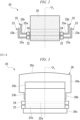
FIG. 2 is a cross-sectional view showing a configuration of a coil for a motor according to the embodiment of the present disclosure. -
FIG. 3 is a front view showing a configuration of the coil for the motor according to the embodiment of the present disclosure. -
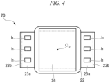
FIG. 4 is a view when the coil for the motor according to the embodiment of the present disclosure is viewed from an inner peripheral side. -
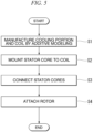
FIG. 5 is a flowchart showing each step of a method for manufacturing a motor according to the embodiment of the present disclosure. -
FIG. 6 is a diagram showing a modified example of a cooling portion according to the embodiment of the present disclosure. -
FIG. 7 is a main enlarged view showing a modified example of the coil for the motor according to the embodiment of the present disclosure. -
FIG. 8 is a main enlarged view showing another modified example of the coil for the motor according to the embodiment of the present disclosure. - Hereinafter, a
motor 100 according to an embodiment of the present disclosure will be described with reference toFIGS. 1 to 4 . As shown inFIG. 1 , themotor 100 includes arotor 1, astator 2, and ahousing 3. Therotor 1 is formed in a columnar shape extending along a main axis O1. Although not shown in detail, a plurality of permanent magnets are arranged in the circumferential direction inside therotor 1. Alternatively, it is also possible to adopt a configuration in which cylindrical magnets are attached to the outer peripheral surface of therotor 1. Therotor 1 is supported to be rotatable around the main axis O1. - The
stator 2 covers therotor 1 from the outer peripheral side. Thestator 2 is formed in an annular shape centered on the main axis O1. Thestator 2 is formed by connecting a plurality of stator cores 26 (to be described later) in the circumferential direction. The configurations of thestator core 26 and acoil 20 for a motor will be described later. Thehousing 3 covers thestator 2 from the outer peripheral side. Thestator 2 is fixed to the inner peripheral surface of thehousing 3 by shrink fitting or the like. - Next, the configuration of the
coil 20 for the motor will be described with reference toFIGS. 2 to 4 . As shown inFIG. 2 , thecoil 20 for the motor includes two coils (an innerperipheral coil 22 and an outer peripheral coil 24) wound around a coil axis O2, acooling portion 23 and acooling portion 25 respectively provided in these coils, and thestator core 26. - The coil axis O2 extends in the radial direction of the main axis O1. The inner
peripheral coil 22 is located on the radially inner side in the direction of the coil axis O2 and the outerperipheral coil 24 is located on the radially outer side in the direction of the coil axis O2. As shown inFIG. 4 , the innerperipheral coil 22 and the outerperipheral coil 24 are wound in a rectangular or circular ring shape when viewed from the direction of the coil axis O2. Further, although not shown in detail, the innerperipheral coil 22 and the outerperipheral coil 24 are electrically connected to each other. The size of the innerperipheral coil 22 is the same as that of the outerperipheral coil 24. Further, the innerperipheral coil 22 and the outerperipheral coil 24 are formed of conductors. - As shown in
FIG. 2 , a pair of thecooling portions 23 are integrally provided in the innerperipheral coil 22. Onecooling portion 23 is provided on one side in the direction of the main axis O1 of the innerperipheral coil 22 and theother cooling portion 23 is provided on the other side in the direction of the main axis O1 of the innerperipheral coil 22. - The
cooling portion 23 includes aprimary portion 23a protruding from the innerperipheral coil 22 toward the radially outer side of the coil axis O2 and asecondary portion 23b extending from the tip of theprimary portion 23a toward a first side in the direction of the coil axis O2. Accordingly, thecooling portion 23 has an L-shaped cross-sectional shape. Further, as shown inFIG. 3 , thesecondary portion 23b has a rectangular shape when viewed from the direction of the main axis O1. Further, as shown inFIG. 4 , at least one of theprimary portion 23a and thesecondary portion 23b is provided with one or more ventilation holes h (three ventilation holes h are formed in theprimary portion 23a as an example inFIG. 4 ). These ventilation holes h are arranged at intervals in the direction of the main axis O1. - Again, as shown in
FIG. 2 , a pair of thecooling portions 25 are integrally provided in the outerperipheral coil 24. Onecooling portion 25 is provided on one side in the direction of the main axis O1 of the outerperipheral coil 24 and theother cooling portion 25 is provided on the other side in the direction of the main axis O1 of the outerperipheral coil 24. That is, thecooling portion 23 of the innerperipheral coil 22 and thecooling portion 25 are provided at the same position in the circumferential direction with respect to the coil axis O2 as an example. Additionally, at least a part of thecooling portion 23 and thecooling portion 25 may overlap each other in the circumferential direction with respect to the axis O2. - The
cooling portion 25 includes aprimary portion 25a protruding from the outerperipheral coil 24 toward the radially outer side of the coil axis O2 and asecondary portion 25b which extends from the tip of theprimary portion 25a toward a first side in the direction of the coil axis O2. Accordingly, thecooling portion 25 has an L-shaped cross-section. Further, as shown inFIG. 3 , thesecondary portion 25b has a rectangular shape when viewed from the direction of the main axis O1. Further, although not shown in the drawings, a plurality of (as an example, three) ventilation holes h are formed in theprimary portion 25a similarly to theprimary portion 23a. Additionally, the same ventilation hole h may be formed in thesecondary portion 25b. Further, the number of the ventilation holes h may be one or more. These ventilation holes h are arranged at intervals in the circumferential direction with respect to the main axis O1. Further, the ventilation hole h of theprimary portion 23a and the ventilation hole h of theprimary portion 25a overlap each other when viewed from the direction of the coil axis O2. - In the cooling
portions FIG. 2 , the protrusion length of theprimary portion 23a of the coolingportion 23 located on the other side in the direction of the coil axis O2 (that is, the radially inner side with respect to the main axis O1) is longer than that of theprimary portion 25a of the coolingportion 25 located on one side in the direction of the coil axis O2. In other words, the radial length with respect to the coil axis O2 of theprimary portion 23a is longer than that of theprimary portion 25a. Further, thesecondary portion 23b corresponding to theprimary portion 23a located on the other side of the coil axis O2 is located on the radially outer side. - Further, as shown in
FIGS. 2 and 3 , at least a part of thesecondary portion 23b of the coolingportion 23 and thesecondary portion 25b of the coolingportion 25 overlap each other in the radial direction with respect to the coil axis O2. Further, thesecondary portion 25b of the coolingportion 25 protrudes toward one side in the direction of the coil axis O2 more than thesecondary portion 23b of the coolingportion 23. Accordingly, at least a part of thesecondary portion 25b of the coolingportion 25 is exposed when viewed from the radial direction of the coil axis O2. - Further, a thin-film insulating layer formed of an enamel resin or the like is provided on the surfaces of the inner
peripheral coil 22, the outerperipheral coil 24, the coolingportion 23, and the coolingportion 25. - Next, the configuration of the
stator core 26 will be described with reference toFIG. 3 . Thestator core 26 is inserted to the inner peripheral side of the innerperipheral coil 22 and the outerperipheral coil 24 formed in a rectangular or circular ring shape. Thestator core 26 includes ayoke portion 26a,teeth 26b, and atip portion 26c. A surface (circumferential surface 26s) on one side in the direction of the coil axis O2 of theyoke portion 26a has an arcuate cross-sectional shape. Accordingly, when the plurality ofstator cores 26 are connected, thecircumferential surfaces 26s are continuous to form a cylindrical surface. - The
teeth 26b protrude from theyoke portion 26a toward the other side in the direction of the coil axis O2. Theteeth 26b have a cross-sectional area smaller than that of theyoke portion 26a when viewed from the direction of the coil axis O2. The innerperipheral coil 22 and the outerperipheral coil 24 are wound on theteeth 26b. Thetip portion 26c is provided on the other side in the direction of the coil axis O2 of theteeth 26b. Thetip portion 26c projects in the radial direction with respect to the coil axis O2. Accordingly, the innerperipheral coil 22 and the outerperipheral coil 24 are held not to fall off from theteeth 26b. - Next, a method for manufacturing the motor 100 (and a method for manufacturing the
coil 20 for the motor) will be described with reference toFIG. 5 . As shown in the same drawing, the method for manufacturing themotor 100 includes step S1 of manufacturing the innerperipheral coil 22, the outerperipheral coil 24, the coolingportion 23, and the coolingportion 25 by additive modeling, step S2 of mounting thestator core 26 on the innerperipheral coil 22 and the outerperipheral coil 24, step S3 of connecting the plurality ofstator cores 26, and step S4 of attaching therotor 1. - In step S1, fine powder metal is layered and hardened using an additive modeling method (AM modeling method) to obtain predetermined shapes of the inner
peripheral coil 22, the outerperipheral coil 24, the coolingportion 23, and the coolingportion 25. Then, the above-described insulating layer is formed on the surfaces of the innerperipheral coil 22, the outerperipheral coil 24, the coolingportion 23, and the coolingportion 25. In step S2, theteeth 26b and thetip portion 26c of thestator core 26 are removed from theyoke portion 26a and then the innerperipheral coil 22 and the outerperipheral coil 24 are mounted on theteeth 26b. Accordingly, thecoil 20 for the motor is completed. In step S3, the plurality ofstator cores 26 of thecoils 20 for motors are connected in the circumferential direction of the main axis O1 to form theannular stator 2. Finally, in step S4, therotor 1 is inserted through thestator 2. With the above steps, all steps related to the method for manufacturing themotor 100 are completed. - Next, an example of the operation of the
motor 100 will be described. When operating themotor 100, a current is first supplied from the outside to the innerperipheral coil 22 and the outerperipheral coil 24. Accordingly, a magnetic field is formed around the innerperipheral coil 22 and the outerperipheral coil 24. An electromagnetic force is generated by the interaction between this magnetic field and the magnetic field of the permanent magnet embedded in therotor 1. Based on this electromagnetic force, therotor 1 rotates around the main axis O1. - Here, the inner
peripheral coil 22 and the outerperipheral coil 24 generate heat in accordance with the operation of themotor 100. As heat generation progresses, the insulating layer may be destroyed and the stable operation of themotor 100 may be affected. Here, in this embodiment, the coolingportion 23 and the coolingportion 25 are provided as described above. - According to the above-described configuration, the heat of the inner
peripheral coil 22 and the outerperipheral coil 24 is released by the coolingportion 23 and the coolingportion 25 and hence an increase in temperature can be avoided. Further, the coolingportions portions coil 20 for the motor can be decreased in size. - Furthermore, according to the above-described configuration, at least a part of the plurality of secondary portion s 23b and 25b do not overlap each other. Accordingly, for example, when blowing air from the outside to the cooling
portions - Further, according to the above-described configuration, since the insulating layer is provided, the cooling
portions portions coil 20 for the motor can be further decreased in size. - Additionally, according to the above-described configuration, the primary portion s 23a and 25a are provided with the ventilation holes h. Accordingly, for example, when blowing air from the outside using a fan or the like, the air can be distributed to each of the cooling
portions rotor 1 in the direction of the main axis O1 to configure the fan. - Further, according to the above-described manufacturing method, since the inner
peripheral coil 22, the outerperipheral coil 24, and the coolingportions coil 20 for the motor in a short time. - As described above, the embodiment of the present disclosure has been described. Additionally, various changes and modifications can be made to the above-described configuration without departing from the gist of the present disclosure. For example, in the above-described embodiment, an example of forming a two-layer coil consisting of the inner
peripheral coil 22 and the outerperipheral coil 24 has been described. However, the number of the coils is not limited to two and may be three or more. - Further, as a modified example of the cooling
portions FIG. 6 . In the example of the same drawing, the secondary portion s 23b and 25b are provided with the opening portion A and thefin portion 27. The opening portion A penetrates the secondary portion s 23b and 25b. Thefin portion 27 projects from the edge of the opening portion A to cover at least a part of the opening portion A. According to this configuration, the heat exhaust efficiency of the secondary portion s 23b and 25b is improved by the opening portion A and thefin portion 27 formed in the secondary portion s 23b and 25b. Accordingly, the heat of the coil can be released more quickly. - Further, as another modified example, as shown in
FIG. 7 , therib 28 can be provided to connect the secondary portion s 23b and 25b in the radial direction of the coil axis O2. According to this configuration, since the secondary portion s 23b and 25b are connected to each other by therib 28, it is possible to reduce the possibility that the secondary portion s 23b and 25b contact each other, for example, when a vibration is generated. Accordingly, it is possible to suppress noise. - In addition, as another modified example, as shown in
FIG. 8 , it is also possible to adopt a configuration in which aconnection portion 29 covering end portions on one side in the direction of the coil axis O2 of two secondary portion s 23b and 25b and connected to thehousing 3 is further provided. Theconnection portion 29 is integrally formed of resin or metal with high thermal conductivity. According to this configuration, the heat of thesecondary portions housing 3 via theconnection portion 29. As a result, it is possible to more efficiently cool themotor 100. - The
coil 20 for the motor, the method for manufacturing thecoil 20 for the motor, and themotor 100 described in each embodiment are understood, for example, as below. -
- (1) The coil 20 for the motor according to a first aspect includes: a coil (the inner peripheral coil 22 and the outer peripheral coil 24) which is formed of a conductor wound around an axis (coil axis O2); and a plurality of cooling portions 23 and 25 which are provided to correspond to different winding layers in the conductor, wherein each of the cooling portions 23 and 25 includes a primary portion 23a and 25a protruding from the winding layer radially outward and a secondary portion 23b and 25b extending from a tip of the primary portion 23a and 25a toward a first side in a direction of the axis, wherein the primary portions 23a and 25a are formed so that the protrusion length of one of the primary portions 23a and 25a, which is located closer to a second side in the direction of the axis than another of the primary portions 23a and 25a, is longer than that of the another of the primary portions 23a and 25a, wherein the secondary portions 23b and 25b are formed so that one of the secondary portions 23b and 25b, which is joined to one of the primary portions 23a and 25a located closer to the second side in the direction of the axis than another of the primary portions, is positioned further outside in the radial direction with respect to another of the secondary portions joined to the another of the primary portions, and wherein at least two of the plurality of secondary portions are arranged to overlap each other at intervals in a radial direction.
- According to the above-described configuration, the heat of the coil is released by the cooling
portions portions primary portions secondary portions secondary portions portions coil 20 for the motor can be decreased in size. - (2) In the
coil 20 for the motor according to a second aspect, thesecondary portion primary portion - According to the above-described configuration, at least a part of the plurality of
secondary portions portions secondary portions - (3) The
coil 20 for the motor according to a third aspect may further include an insulating layer which is formed on surfaces of the coil and the coolingportion - According to the above-described configuration, since the insulating layer is provided, the cooling
portions portions coil 20 for the motor can be further decreased in size. - (4) In the
coil 20 for the motor according to a fourth aspect, thecoil 20 is provided with at least one of a ventilation hole h penetrating theprimary portion secondary portion - According to the above-described configuration, since the ventilation hole is formed in at least one of the primary portion s 23a and 25a and the secondary portion s 23b and 25b, air can be distributed to each of the cooling
portions
Accordingly, it is possible to more efficiently cool the coil. - (5) In the
coil 20 for the motor according to a fifth aspect, thesecondary portion fin portion 27 covering at least a part of the opening portion A. - According to the above-described configuration, the heat exhaust efficiency of the secondary portion s 23b and 25b is improved by the opening portion A and the
fin portion 27 formed in the secondary portion s 23b and 25b. Accordingly, the heat of the coil can be released more quickly. - (6) The
coil 20 for the motor according to a sixth aspect may further include arib 28 connecting thesecondary portions - According to the above-described configuration, since the
secondary portions rib 28, it is possible to reduce the possibility that thesecondary portions - (7) The
coil 20 for the motor according to a seventh aspect may further include: aconnection portion 29 covering end portions of the plurality ofsecondary portions housing 3. - According to the above-described configuration, the heat of the secondary portion s 23b and 25b can be released to the
housing 3 via theconnection portion 29. - (8) The
motor 100 according to an eighth aspect includes: therotor 1 having a permanent magnet; a plurality ofstator cores 26 which are annularly connected each other to surround an outer periphery of the rotor1; and thecoil 20 for the motor according to any one of the above-described aspects in which thestator core 26 is inserted through an inner peripheral side of the coil. - According to the above-described configuration, it is possible to provide the
motor 100 that is more compact and has improved cooling efficiency. - (9) A method for manufacturing the coil 20 for the motor according to a ninth aspect is a method for manufacturing a coil 20 for a motor including a coil (the inner peripheral coil 22 and the outer peripheral coil 24) formed of a conductor wound around an axis (coil axis O2) and a plurality of cooling portions 23 and 25 provided to correspond to different winding layers in the conductor, each of the cooling portions 23 and 25 including a primary portion 23a and 25a protruding from the winding layer radially outward and a secondary portion 23b and 25b extending from a tip of the primary portion 23a and 25a toward a first side in a direction of the axis, the primary portions 23a and 25a being formed so that the protrusion length of one of the primary portions 23a and 25a, which is located closer to a second side in the direction of the axis than another of the primary portions 23a and 25a, is longer than that of another of the primary portions 23a and 25a, the secondary portions 23b and 25b being formed so that one of the secondary portion 23b and 25b, which is joined to one of the primary portion 23a and 25a located closer to the second side in the direction of the axis than another of the primary portions 23a and 25a, is positioned further outside in the radial direction with respect to another of the secondary portions 23b and 25b joined to the another of the secondary portion s 23b and 25b, and at least a two of the plurality of secondary portions 23b and 25b being arranged to overlap each other at intervals in a radial direction, the method including: a step (step S1) of integrally forming the coil and the cooling portion 23 and 25 by additive modeling..
- According to the above-described configuration, since the coil and the cooling
portions coil 20 for the motor in a short time. - According to the present disclosure, it is possible to provide a coil for a motor, a method for manufacturing a coil for a motor, and a motor that can be easily manufactured and decreased in size.
-
- 100 Motor
- 1 Rotor
- 2 Stator
- 3 Housing
- 20 Coil for motor
- 22 Inner peripheral coil
- 23 Cooling portion
- 23a Primary portion
- 23b Secondary portion
- 24 Outer peripheral coil
- 25 Cooling portion
- 25a Primary portion
- 25b Secondary portion
- 26 Stator core
- 26a Yoke portion
- 26b Teeth
- 26c Tip portion
- 27 Fin portion
- 28 Rib
- 29 Connection portion
- A Opening portion
- h Ventilation hole
- O1 Main axis
- O2 Coil axis
Claims (9)
- A coil for a motor comprising:a coil which is formed of a conductor wound around an axis; anda plurality of cooling portions which are provided to correspond to different winding layers in the conductor,wherein each of the cooling portions includes a primary portion protruding from the winding layer radially outward and a secondary portion extending from a tip of the primary portion toward a first side in a direction of the axis,wherein the primary portions are formed so that the protrusion length of one of the primary portions, which is located closer to a second side in the direction of the axis than another of the primary portions, is longer than that of the another of the primary portions,wherein the secondary portions are formed so that one of the secondary portions, which is joined to one of the primary portions located closer to the second side in the direction of the axis than another of the primary portions, is positioned further outside in the radial direction with respect to another of the secondary portions joined to the another of the primary portions, andwherein at least two of the plurality of secondary portions are arranged to overlap each other at intervals in a radial direction.
- The coil for the motor according to claim 1,
wherein the secondary portion joined to the primary portion located on the first side in the direction of the axis protrudes more toward the first side in the direction of the axis. - The coil for the motor according to claim 1 or 2, further comprising:
an insulating layer which is formed on surfaces of the coil and the cooling portion. - The coil for the motor according to any one of claims 1 to 3,
wherein the coil is provided with at least one of a ventilation hole penetrating the primary portion in a radial direction and another ventilation hole penetrating the secondary portion in a circumferential direction. - The coil for the motor according to any one of claims 1 to 4,
wehrein the secondary portion is provided with an opening portion and a fin portion covering at least a part of the opening portion. - The coil for the motor according to any one of claims 1 to 5, further comprising:
a rib connecting the secondary portions adjacent to each other. - The coil for the motor according to any one of claims 1 to 6, further comprising:
a connection portion covering end portions of the plurality of secondary portions on the first side in the direction of the axis and being connected to a housing. - A motor comprising:a rotor having a permanent magnet;a plurality of stator cores which are annularly connected each other to surround an outer periphery of the rotor; andthe coil for the motor according to any one of claims 1 to 7 in which the stator core is inserted through an inner peripheral side of the coil.
- A method for manufacturing a coil for a motor including a coil formed of a conductor wound around an axis and a plurality of cooling portions provided to correspond to different winding layers in the conductor, each of the cooling portions including a primary portion protruding from the winding layer radially outward and a secondary portion extending from a tip of the primary portion toward a first side in a direction of the axis, the primary portions being formed so that the protrusion length of one of the primary portions, which is located closer to a second side in the direction of the axis than another of the primary portions, is longer than that of another of the primary portions, the secondary portions being formed so that one of the secondary portion, which is joined to one of the primary portion located closer to the second side in the direction of the axis than another of the primary portions, is positioned further outside in the radial direction with respect to another of the secondary portions joined to the another of the secondary portions, and at least a two of the plurality of secondary portions being arranged to overlap each other at intervals in a radial direction, the method comprising:
integrally forming the coil and the cooling portion by additive modeling.
Applications Claiming Priority (2)
| Application Number | Priority Date | Filing Date | Title |
|---|---|---|---|
| JP2021063463A JP7685860B2 (en) | 2021-04-02 | 2021-04-02 | Coil for electric motor, manufacturing method for coil for electric motor, and electric motor |
| PCT/JP2022/005859 WO2022209370A1 (en) | 2021-04-02 | 2022-02-15 | Coil for motor, method for manufacturing coil for motor, and motor |
Publications (2)
| Publication Number | Publication Date |
|---|---|
| EP4318889A1 true EP4318889A1 (en) | 2024-02-07 |
| EP4318889A4 EP4318889A4 (en) | 2024-10-23 |
Family
ID=83458366
Family Applications (1)
| Application Number | Title | Priority Date | Filing Date |
|---|---|---|---|
| EP22779597.8A Pending EP4318889A4 (en) | 2021-04-02 | 2022-02-15 | COIL FOR MOTOR, METHOD FOR MANUFACTURING A COIL FOR MOTOR AND MOTOR |
Country Status (4)
| Country | Link |
|---|---|
| US (1) | US12463483B2 (en) |
| EP (1) | EP4318889A4 (en) |
| JP (1) | JP7685860B2 (en) |
| WO (1) | WO2022209370A1 (en) |
Families Citing this family (1)
| Publication number | Priority date | Publication date | Assignee | Title |
|---|---|---|---|---|
| WO2025150318A1 (en) * | 2024-01-10 | 2025-07-17 | パナソニックIpマネジメント株式会社 | Stator and rotary electrical machine |
Family Cites Families (11)
| Publication number | Priority date | Publication date | Assignee | Title |
|---|---|---|---|---|
| DE1799308U (en) * | 1958-01-29 | 1959-11-05 | Hans Still Ag | ARRANGEMENT FOR COOLING FIELD WINDINGS OF ELECTRIC MACHINES WITH DETAILED POLES. |
| CH627885A5 (en) * | 1978-05-24 | 1982-01-29 | Bbc Brown Boveri & Cie | Pole coil of a multipole electrical machine |
| JP4026496B2 (en) * | 2002-12-26 | 2007-12-26 | 日産自動車株式会社 | Cooling structure of rotating electric machine |
| GB2403606A (en) * | 2003-07-03 | 2005-01-05 | Alstom | Salient pole rotor with embedded heat sink |
| WO2012059790A1 (en) * | 2010-11-05 | 2012-05-10 | Nanto Srl | Projector with solid state light sources for street lighting or the like |
| JP2016039662A (en) | 2014-08-06 | 2016-03-22 | パナソニックIpマネジメント株式会社 | Electric motor |
| JP2016163377A (en) * | 2015-02-27 | 2016-09-05 | 株式会社明電舎 | Rotary machine |
| CN204820086U (en) * | 2015-07-29 | 2015-12-02 | 深圳市欧普特工业材料有限公司 | A cooling module for production of organosilicon casting glue |
| WO2018164024A1 (en) * | 2017-03-06 | 2018-09-13 | 株式会社 明電舎 | Insulating structure of ventilation path of salient-pole rotor |
| JP2020108313A (en) * | 2018-12-28 | 2020-07-09 | 株式会社マキタ | Distributed winding motor for power tool and power tool |
| JP2021063463A (en) | 2019-10-15 | 2021-04-22 | トヨタ自動車株式会社 | Control device for internal combustion engine |
-
2021
- 2021-04-02 JP JP2021063463A patent/JP7685860B2/en active Active
-
2022
- 2022-02-15 US US18/284,698 patent/US12463483B2/en active Active
- 2022-02-15 EP EP22779597.8A patent/EP4318889A4/en active Pending
- 2022-02-15 WO PCT/JP2022/005859 patent/WO2022209370A1/en not_active Ceased
Also Published As
| Publication number | Publication date |
|---|---|
| US12463483B2 (en) | 2025-11-04 |
| JP2022158507A (en) | 2022-10-17 |
| EP4318889A4 (en) | 2024-10-23 |
| US20240186856A1 (en) | 2024-06-06 |
| WO2022209370A1 (en) | 2022-10-06 |
| JP7685860B2 (en) | 2025-05-30 |
Similar Documents
| Publication | Publication Date | Title |
|---|---|---|
| JP5965228B2 (en) | Axial gap type rotating electrical machine | |
| JP4946276B2 (en) | motor | |
| JP2004194367A (en) | Rotating electric machines and wiring members | |
| JP7774019B2 (en) | Stator Structure | |
| JP2003164089A (en) | Stator of rotating field electric motor and its production method | |
| US12463483B2 (en) | Coil for motor, method for manufacturing coil for motor, and motor | |
| JP2019126143A (en) | Rotary electric machine | |
| US8823240B2 (en) | Stator and rotating electrical machine | |
| US11437872B2 (en) | Electric machine with stator segments and winding supports | |
| CN111226382B (en) | Electric machine | |
| JP6200854B2 (en) | Rotating electric machine stator | |
| JPWO2018138853A1 (en) | Axial gap type rotating electrical machine | |
| JP7632209B2 (en) | Armature and motor | |
| JP5884463B2 (en) | Rotating electric machine | |
| EP3796526B1 (en) | Molded motor | |
| JPWO2015040692A1 (en) | Rotating electric machine stator | |
| TWI841653B (en) | Bobbin structure of armature | |
| EP4175127A1 (en) | Motor | |
| JP2009268245A (en) | Stator for rotary electric machine | |
| JP6776850B2 (en) | Rotating machine | |
| US10348175B2 (en) | Rotor, manufacturing method of the rotor, and DC motor | |
| WO2020054199A1 (en) | Molded motor | |
| US20250038612A1 (en) | Motor and blower | |
| CN115241999A (en) | Stator construction and resolver | |
| US20240322620A1 (en) | Electric motor |
Legal Events
| Date | Code | Title | Description |
|---|---|---|---|
| STAA | Information on the status of an ep patent application or granted ep patent |
Free format text: STATUS: THE INTERNATIONAL PUBLICATION HAS BEEN MADE |
|
| PUAI | Public reference made under article 153(3) epc to a published international application that has entered the european phase |
Free format text: ORIGINAL CODE: 0009012 |
|
| STAA | Information on the status of an ep patent application or granted ep patent |
Free format text: STATUS: REQUEST FOR EXAMINATION WAS MADE |
|
| 17P | Request for examination filed |
Effective date: 20231030 |
|
| AK | Designated contracting states |
Kind code of ref document: A1 Designated state(s): AL AT BE BG CH CY CZ DE DK EE ES FI FR GB GR HR HU IE IS IT LI LT LU LV MC MK MT NL NO PL PT RO RS SE SI SK SM TR |
|
| DAV | Request for validation of the european patent (deleted) | ||
| DAX | Request for extension of the european patent (deleted) | ||
| A4 | Supplementary search report drawn up and despatched |
Effective date: 20240925 |
|
| RIC1 | Information provided on ipc code assigned before grant |
Ipc: H02K 9/02 20060101ALI20240919BHEP Ipc: H02K 9/22 20060101ALI20240919BHEP Ipc: H02K 15/06 20060101ALI20240919BHEP Ipc: H02K 15/04 20060101ALI20240919BHEP Ipc: H02K 3/24 20060101AFI20240919BHEP |