EP4318878A1 - Battery management apparatus and communication method therefor in battery rack system - Google Patents
Battery management apparatus and communication method therefor in battery rack system Download PDFInfo
- Publication number
- EP4318878A1 EP4318878A1 EP22895817.9A EP22895817A EP4318878A1 EP 4318878 A1 EP4318878 A1 EP 4318878A1 EP 22895817 A EP22895817 A EP 22895817A EP 4318878 A1 EP4318878 A1 EP 4318878A1
- Authority
- EP
- European Patent Office
- Prior art keywords
- battery pack
- battery
- identifier
- management apparatus
- electromagnetic induction
- Prior art date
- Legal status (The legal status is an assumption and is not a legal conclusion. Google has not performed a legal analysis and makes no representation as to the accuracy of the status listed.)
- Pending
Links
- 238000004891 communication Methods 0.000 title claims abstract description 62
- 238000000034 method Methods 0.000 title claims abstract description 34
- 230000005674 electromagnetic induction Effects 0.000 claims abstract description 45
- 230000004044 response Effects 0.000 claims abstract description 10
- 230000002618 waking effect Effects 0.000 claims description 2
- 238000010586 diagram Methods 0.000 description 6
- 230000008569 process Effects 0.000 description 2
- 238000012545 processing Methods 0.000 description 2
- 230000008901 benefit Effects 0.000 description 1
- 238000011161 development Methods 0.000 description 1
- 230000000694 effects Effects 0.000 description 1
- 238000004146 energy storage Methods 0.000 description 1
- 238000005516 engineering process Methods 0.000 description 1
- 230000006870 function Effects 0.000 description 1
- 230000006698 induction Effects 0.000 description 1
- 238000012986 modification Methods 0.000 description 1
- 230000004048 modification Effects 0.000 description 1
Images


Classifications
-
- H—ELECTRICITY
- H02—GENERATION; CONVERSION OR DISTRIBUTION OF ELECTRIC POWER
- H02J—CIRCUIT ARRANGEMENTS OR SYSTEMS FOR SUPPLYING OR DISTRIBUTING ELECTRIC POWER; SYSTEMS FOR STORING ELECTRIC ENERGY
- H02J50/00—Circuit arrangements or systems for wireless supply or distribution of electric power
- H02J50/80—Circuit arrangements or systems for wireless supply or distribution of electric power involving the exchange of data, concerning supply or distribution of electric power, between transmitting devices and receiving devices
-
- H—ELECTRICITY
- H01—ELECTRIC ELEMENTS
- H01M—PROCESSES OR MEANS, e.g. BATTERIES, FOR THE DIRECT CONVERSION OF CHEMICAL ENERGY INTO ELECTRICAL ENERGY
- H01M10/00—Secondary cells; Manufacture thereof
- H01M10/42—Methods or arrangements for servicing or maintenance of secondary cells or secondary half-cells
- H01M10/4221—Methods or arrangements for servicing or maintenance of secondary cells or secondary half-cells with battery type recognition
-
- H—ELECTRICITY
- H01—ELECTRIC ELEMENTS
- H01M—PROCESSES OR MEANS, e.g. BATTERIES, FOR THE DIRECT CONVERSION OF CHEMICAL ENERGY INTO ELECTRICAL ENERGY
- H01M10/00—Secondary cells; Manufacture thereof
- H01M10/42—Methods or arrangements for servicing or maintenance of secondary cells or secondary half-cells
- H01M10/425—Structural combination with electronic components, e.g. electronic circuits integrated to the outside of the casing
-
- H—ELECTRICITY
- H02—GENERATION; CONVERSION OR DISTRIBUTION OF ELECTRIC POWER
- H02J—CIRCUIT ARRANGEMENTS OR SYSTEMS FOR SUPPLYING OR DISTRIBUTING ELECTRIC POWER; SYSTEMS FOR STORING ELECTRIC ENERGY
- H02J50/00—Circuit arrangements or systems for wireless supply or distribution of electric power
- H02J50/10—Circuit arrangements or systems for wireless supply or distribution of electric power using inductive coupling
-
- H—ELECTRICITY
- H02—GENERATION; CONVERSION OR DISTRIBUTION OF ELECTRIC POWER
- H02J—CIRCUIT ARRANGEMENTS OR SYSTEMS FOR SUPPLYING OR DISTRIBUTING ELECTRIC POWER; SYSTEMS FOR STORING ELECTRIC ENERGY
- H02J50/00—Circuit arrangements or systems for wireless supply or distribution of electric power
- H02J50/40—Circuit arrangements or systems for wireless supply or distribution of electric power using two or more transmitting or receiving devices
-
- H—ELECTRICITY
- H02—GENERATION; CONVERSION OR DISTRIBUTION OF ELECTRIC POWER
- H02J—CIRCUIT ARRANGEMENTS OR SYSTEMS FOR SUPPLYING OR DISTRIBUTING ELECTRIC POWER; SYSTEMS FOR STORING ELECTRIC ENERGY
- H02J7/00—Circuit arrangements for charging or depolarising batteries or for supplying loads from batteries
- H02J7/0047—Circuit arrangements for charging or depolarising batteries or for supplying loads from batteries with monitoring or indicating devices or circuits
-
- H—ELECTRICITY
- H04—ELECTRIC COMMUNICATION TECHNIQUE
- H04B—TRANSMISSION
- H04B5/00—Near-field transmission systems, e.g. inductive or capacitive transmission systems
- H04B5/20—Near-field transmission systems, e.g. inductive or capacitive transmission systems characterised by the transmission technique; characterised by the transmission medium
- H04B5/24—Inductive coupling
- H04B5/26—Inductive coupling using coils
- H04B5/266—One coil at each side, e.g. with primary and secondary coils
-
- H—ELECTRICITY
- H01—ELECTRIC ELEMENTS
- H01M—PROCESSES OR MEANS, e.g. BATTERIES, FOR THE DIRECT CONVERSION OF CHEMICAL ENERGY INTO ELECTRICAL ENERGY
- H01M10/00—Secondary cells; Manufacture thereof
- H01M10/42—Methods or arrangements for servicing or maintenance of secondary cells or secondary half-cells
- H01M10/425—Structural combination with electronic components, e.g. electronic circuits integrated to the outside of the casing
- H01M2010/4278—Systems for data transfer from batteries, e.g. transfer of battery parameters to a controller, data transferred between battery controller and main controller
-
- H—ELECTRICITY
- H02—GENERATION; CONVERSION OR DISTRIBUTION OF ELECTRIC POWER
- H02J—CIRCUIT ARRANGEMENTS OR SYSTEMS FOR SUPPLYING OR DISTRIBUTING ELECTRIC POWER; SYSTEMS FOR STORING ELECTRIC ENERGY
- H02J13/00—Circuit arrangements for providing remote indication of network conditions, e.g. an instantaneous record of the open or closed condition of each circuitbreaker in the network; Circuit arrangements for providing remote control of switching means in a power distribution network, e.g. switching in and out of current consumers by using a pulse code signal carried by the network
- H02J13/00002—Circuit arrangements for providing remote indication of network conditions, e.g. an instantaneous record of the open or closed condition of each circuitbreaker in the network; Circuit arrangements for providing remote control of switching means in a power distribution network, e.g. switching in and out of current consumers by using a pulse code signal carried by the network characterised by monitoring
-
- H—ELECTRICITY
- H02—GENERATION; CONVERSION OR DISTRIBUTION OF ELECTRIC POWER
- H02J—CIRCUIT ARRANGEMENTS OR SYSTEMS FOR SUPPLYING OR DISTRIBUTING ELECTRIC POWER; SYSTEMS FOR STORING ELECTRIC ENERGY
- H02J7/00—Circuit arrangements for charging or depolarising batteries or for supplying loads from batteries
- H02J7/00032—Circuit arrangements for charging or depolarising batteries or for supplying loads from batteries characterised by data exchange
- H02J7/00036—Charger exchanging data with battery
-
- Y—GENERAL TAGGING OF NEW TECHNOLOGICAL DEVELOPMENTS; GENERAL TAGGING OF CROSS-SECTIONAL TECHNOLOGIES SPANNING OVER SEVERAL SECTIONS OF THE IPC; TECHNICAL SUBJECTS COVERED BY FORMER USPC CROSS-REFERENCE ART COLLECTIONS [XRACs] AND DIGESTS
- Y02—TECHNOLOGIES OR APPLICATIONS FOR MITIGATION OR ADAPTATION AGAINST CLIMATE CHANGE
- Y02E—REDUCTION OF GREENHOUSE GAS [GHG] EMISSIONS, RELATED TO ENERGY GENERATION, TRANSMISSION OR DISTRIBUTION
- Y02E60/00—Enabling technologies; Technologies with a potential or indirect contribution to GHG emissions mitigation
- Y02E60/10—Energy storage using batteries
Definitions
- the present invention relates to a battery management apparatus in a battery rack system and a communication method thereof, and more particularly, to a battery management apparatus for performing wireless communication in a battery rack system including a plurality of battery packs and a communication method thereof.
- An energy storage system is provided with a battery rack system including at least one battery pack and a battery rack.
- the battery packs are managed by communicating with one another using battery management systems (BMS) which are individually accommodated in the battery rack and the at least one battery pack.
- BMS battery management systems
- communication is performed by connecting a battery management apparatus of the battery rack and at least one battery management apparatus of the at least one battery pack through a communication cable.
- an object of the present invention is to provide an apparatus for managing a battery system.
- another object of the present invention is to provide a battery control method.
- a battery management apparatus of a first battery pack may comprise a wireless communication module, a first electromagnetic induction coil, a second electromagnetic induction coil, and a controller configured to wake up in response to power supplied from a battery management apparatus of the battery rack through the first electromagnetic induction coil, to receive information about an identifier of the first battery pack from the battery management apparatus of the battery rack through the wireless communication module, to allocate an identifier to the first battery pack based on the information about the identifier of the first battery pack, and to supply power to a second battery pack located near the first battery pack through the second electromagnetic induction coil.
- the controller may control the wireless communication module to transmit information on an identifier of the second battery pack to the second battery pack when the second battery pack wakes up according to the power supplied.
- the second battery pack may be a battery pack positioned closest to the first battery pack among the plurality of battery packs.
- the identifier of the second battery pack may be assigned a number next to the identifier of the first battery pack.
- the controller may transmit information on the identifier allocated to the first battery pack to the battery rack through the wireless communication module.
- a battery management apparatus of a battery rack including a plurality of battery packs may comprise an electromagnetic induction coil, a wireless communication module, and a controller configured to apply power to a first battery pack among the plurality of battery packs through the electromagnetic induction coil to wake up the first battery pack and to transmit information about an identifier of the first battery pack through the wireless communication module to the woken up first battery pack.
- the first battery pack may allocate an identifier to the first battery pack based on the information about the identifier of the first battery pack, and supply power to a second battery pack through an electromagnetic induction coil of the first battery pack.
- the first battery pack may control the wireless communication module to transmit information on an identifier of the second battery pack to the second battery pack when the second battery pack wakes up according to the power supplied.
- the second battery pack may allocate an identifier to the second battery pack based on the information about the identifier of the second battery pack, and supply power to a third battery pack through an electromagnetic induction coil of the second battery pack.
- the controller may receive information about a plurality of identifiers individually allocated to the plurality of battery packs, from the plurality of battery packs.
- a wireless communication method of a battery management apparatus in a first battery pack among a plurality of battery packs included in a battery rack may comprise waking up in response to power supplied from a battery management apparatus of the battery rack through a first electromagnetic induction coil and receiving information about an identifier of the first battery pack from the battery management apparatus of the battery rack; allocating an identifier to the first battery pack based on the information about the identifier of the first battery pack; and supplying power to a second battery pack located near the first battery pack through a second electromagnetic induction coil.
- the wireless communication method may further comprise transmitting information on an identifier of the second battery pack to the second battery pack in the instance that the second battery pack wakes up according to the power supplied.
- the second battery pack may be a battery pack positioned closest to the first battery pack among the plurality of battery packs.
- the identifier of the second battery pack may be assigned a number next to the identifier of the first battery pack.
- the wireless communication method may further comprise transmitting information on the identifier allocated to the first battery pack to the battery rack.
- a battery management apparatus and a communication method thereof in a battery rack system wake up in response to power supplied from a battery management apparatus of the battery rack through the first electromagnetic induction coil, receive information about an identifier of the first battery pack from the battery management apparatus of the battery rack through the wireless communication module, allocate an identifier to the first battery pack based on the information about the identifier of the first battery pack, and supply power to a second battery pack located near the first battery pack through the second electromagnetic induction coil, thereby providing a battery management apparatus and a communication method thereof in a battery rack system with high-efficiency and low-reliability, which is capable of performing wireless communication among a battery rack and at least one battery packs in a battery rack system, provided wirelessly without a communication cable.
- first, second, A, B, and the like may be used herein to describe various elements, these elements should not be limited by these terms. These terms are only used to distinguish one element from another. For example, a first element could be termed a second element, and, similarly, a second element could be termed a first element, without departing from the scope of the present invention.
- the term "and/or" includes combinations of a plurality of associated listed items or any of the plurality of associated listed items.
- FIG. 1 is a conceptual diagram of a typical battery rack system.
- a typical battery rack system includes at least one battery pack and a battery rack including the same, and each of the battery rack and the at least one battery pack includes a battery management apparatus.
- the battery rack and the at least one battery pack may typically communicate through a communication cable L.
- the battery rack and the at least one battery pack may transmit and receive a wake signal and identifier information among them adjacent to each other using a communication cable L.
- the typical battery rack system has a limitation of supporting only wired communication using a communication cable. Accordingly, in the present invention, a battery rack system supporting wireless communication will be described in detail.
- FIG. 2 is a conceptual diagram of a battery rack system according to embodiments of the present invention.
- a battery rack system may include at least one battery pack.
- Each of the at least one battery pack may include a pack battery management apparatus (Pack Battery Management System; Pack BMS), and the battery rack may include a rack battery management apparatus (Rack BMS) for controlling the pack battery management apparatus (Pack BMS) of the at least one battery pack.
- Pack BMS Pack Battery Management System
- Rack BMS rack battery management apparatus
- a battery management apparatus may include a wireless communication module, an electromagnetic induction coil, and a controller.
- the wireless communication module is for providing a wireless communication function to the battery management system, and may include, for example, at least one of a Wi-Fi module, a Bluetooth module, and a ZigBee module. According to an embodiment, information on a pack identifier may be transmitted and received between battery management apparatuses through a wireless communication module.
- the electromagnetic induction coil may include a first electromagnetic induction coil receiving power and a second electromagnetic induction coil supplying power.
- the battery management apparatus (Rack BMS) of the battery rack may be configured without a first electromagnetic induction coil for receiving power.
- the controller may control the operations of the wireless communication module and the electromagnetic induction coil.
- FIG. 3 is a block diagram of a battery management apparatus according to embodiments of the present invention.
- the battery management apparatus may include a memory 100, a processor 200, a transceiver 300, an input interface 400, an output interface 500, and a storage device 600.
- the processor 200 of FIG. 3 may be a controller (e.g., MCU; microcontroller unit of FIG. 2 ) of the present invention.
- each of the components 100, 200, 300, 400, 500, and 600 included in the battery management apparatus may be connected by a bus 700 to communicate with one another.
- the memory 100 and the storage device 600 may include at least one of a volatile storage medium and a non-volatile storage medium.
- the memory 100 and the storage device 600 may include at least one of a read only memory (ROM) and a random access memory (RAM).
- the memory 100 may include at least one command/instruction executed by the processor 200 to control operations of the wireless communication module.
- the at least one instruction may include an instruction to wake up in response to power supplied from a battery management apparatus of the battery rack through the first electromagnetic induction coil, an instruction to receive information about an identifier of the first battery pack from the battery management apparatus of the battery rack through the wireless communication module, an instruction to allocate an identifier to the first battery pack based on the information about the identifier of the first battery pack, and an instruction to supply power to a second battery pack located near the first battery pack through the second electromagnetic induction coil.
- the processor 200 may mean a central processing unit (CPU), a graphics processing unit (GPU), or a dedicated processor on which methods according to embodiments of the present invention are performed.
- CPU central processing unit
- GPU graphics processing unit
- dedicated processor on which methods according to embodiments of the present invention are performed.
- the processor 200 may execute at least one program command stored in the memory 100 .
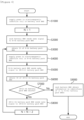
- FIG. 4 is a flowchart illustrating a wireless communication method of a battery management apparatus in a battery rack system according to embodiments of the present invention.
- the battery management apparatus R in the battery rack may supply power to the electromagnetic induction coil (S1000). Accordingly, the battery management apparatus R in the battery rack may supply power to a first electromagnetic induction coil of the first battery pack located in a short distance through electromagnetic induction by the induction coil.
- the power may be called a wake signal which wakes up the battery management apparatus of the first battery pack.
- a battery management apparatus P1 in the first battery pack may wake up when power is supplied through the first electromagnetic induction coil (S2000), and receive information on the identifier from the battery management apparatus R in the battery rack through a wireless communication module(S3000). Accordingly, the battery management apparatus P1 of the first battery pack may allocate an identifier to the first battery pack based on the identifier information.
- the battery management apparatus R of the battery rack may be positioned closest to the battery management apparatus P1 of the first battery pack.
- the battery management apparatus P1 of the first battery pack may apply power to the second electromagnetic induction coil (S4000). Accordingly, the battery management apparatus P1 of the first battery pack may supply power to the battery management apparatus P2 of the second battery pack located in a short distance through electromagnetic induction by the second electromagnetic induction coil of first battery pack. In other words, the battery management apparatus P1 of the first battery pack may transmit a wake signal to the battery management apparatus P2 of the second battery pack (S5000).
- the battery management apparatus P2 of the second battery pack may receive information about an identifier from the battery management apparatus P1 of the first battery pack through a wireless communication module (S6000). Accordingly, the battery management apparatus P2 of the second battery pack may allocate an identifier to the second battery pack based on the identifier information.
- the battery management apparatus P1 of the first battery pack may be a device that is positioned closest to the battery management apparatus P2 of the second battery pack and is capable of communication.
- the battery management apparatus P2 of the second battery pack may receive information about the identifier of the second battery pack from the battery management apparatus P1 of the first battery pack that is capable of communication and located in the closest location.
- the identifier of the second battery pack may be sequentially assigned to a number following the identifier assigned to the battery management apparatus P1 of the first battery pack that is capable of communication and is located closest to the second battery pack.
- the battery management apparatus P2 of the second battery pack may check whether there is a battery management apparatus of the third battery pack in a close range capable of communication using electromagnetic induction by the second electromagnetic induction coil (S7000).
- the battery management apparatus P2 for the second battery pack may transmit a wake signal to the battery management apparatus of the third battery pack through a second electromagnetic induction coil (S8000).
- the battery management apparatus of the third battery pack may repeatedly perform steps S3000 to S8000 until there is no battery management apparatus of another battery pack in the vicinity.
- the battery management apparatus R of the battery rack may determine that identifiers are allocated to each of all battery packs included in the battery rack and terminate the identifier allocation process. For example, when 17 battery packs are included in a battery rack, the battery management apparatus R may terminate the process for allocating identifiers when information on 17 identifiers is received.
- the battery management apparatus R of the battery rack may obtain configuration information of the battery rack system based on the information about the identifiers, each received from the battery management apparatuses P of the battery packs (S9000).
- a battery management apparatus and a communication method thereof in a battery rack system according to embodiments of the present invention have been described above.
- a battery management apparatus and a communication method thereof in a battery rack system wake up in response to power supplied from a battery management apparatus of the battery rack through the first electromagnetic induction coil, receive information about an identifier of the first battery pack from the battery management apparatus of the battery rack through the wireless communication module, allocate an identifier to the first battery pack based on the information about the identifier of the first battery pack, and supply power to a second battery pack located near the first battery pack through the second electromagnetic induction coil, thereby providing a battery management apparatus and a communication method thereof in a battery rack system with high-efficiency and low-reliability, which is capable of performing wireless communication among a battery rack and at least one battery packs in a battery rack system, provided wirelessly without a communication cable.
- the operations of the method according to the embodiments of the present invention may be implemented as a computer-readable program or code on a computer-readable recording medium.
- the computer-readable recording medium includes all types of recording devices in which data readable by a computer system is stored.
- the computer-readable recording medium may be distributed in a network-connected computer system to store and execute computer-readable programs or codes in a distributed manner.
- the computer-readable recording medium may include a hardware device, such as a ROM, a RAM, and a flash memory, specially configured to store and execute program instructions.
- the program instructions may include not only machine language codes such as those generated by a compiler, but also high-level language codes that can be executed by a computer by using an interpreter or the like.
- a block or apparatus corresponds to a method step or feature of a method step.
- aspects described in the context of a method may also represent a feature of a corresponding block or item or a corresponding apparatus.
- Some or all of the method steps may be performed by (or using) a hardware device, such as, for example, a microprocessor, a programmable computer, or an electronic circuit. In some embodiments, one or more of the most important method steps may be performed by such an apparatus.
Landscapes
- Engineering & Computer Science (AREA)
- Computer Networks & Wireless Communication (AREA)
- Power Engineering (AREA)
- Chemical Kinetics & Catalysis (AREA)
- Manufacturing & Machinery (AREA)
- Chemical & Material Sciences (AREA)
- Electrochemistry (AREA)
- General Chemical & Material Sciences (AREA)
- Microelectronics & Electronic Packaging (AREA)
- Signal Processing (AREA)
- Charge And Discharge Circuits For Batteries Or The Like (AREA)
- Battery Mounting, Suspending (AREA)
- Arrangements For Transmission Of Measured Signals (AREA)
- Secondary Cells (AREA)
Applications Claiming Priority (2)
| Application Number | Priority Date | Filing Date | Title |
|---|---|---|---|
| KR1020210159464A KR20230072833A (ko) | 2021-11-18 | 2021-11-18 | 배터리 랙 시스템에서의 배터리 관리 장치 및 이의 통신 방법 |
| PCT/KR2022/013775 WO2023090608A1 (ko) | 2021-11-18 | 2022-09-15 | 배터리 랙 시스템에서의 배터리 관리 장치 및 이의 통신 방법 |
Publications (1)
| Publication Number | Publication Date |
|---|---|
| EP4318878A1 true EP4318878A1 (en) | 2024-02-07 |
Family
ID=86397286
Family Applications (1)
| Application Number | Title | Priority Date | Filing Date |
|---|---|---|---|
| EP22895817.9A Pending EP4318878A1 (en) | 2021-11-18 | 2022-09-15 | Battery management apparatus and communication method therefor in battery rack system |
Country Status (5)
| Country | Link |
|---|---|
| EP (1) | EP4318878A1 (ko) |
| JP (1) | JP2024517634A (ko) |
| KR (1) | KR20230072833A (ko) |
| CN (1) | CN117223192A (ko) |
| WO (1) | WO2023090608A1 (ko) |
Family Cites Families (6)
| Publication number | Priority date | Publication date | Assignee | Title |
|---|---|---|---|---|
| US8525477B2 (en) * | 2010-07-15 | 2013-09-03 | O2Micro, Inc. | Assigning addresses to multiple cascade battery modules in electric or electric hybrid vehicles |
| EP2765643B1 (en) * | 2011-10-07 | 2016-09-14 | Hitachi Automotive Systems, Ltd. | Controller and battery monitoring system |
| KR102415123B1 (ko) | 2015-08-13 | 2022-06-30 | 삼성에스디아이 주식회사 | 배터리 팩 및 이를 포함하는 에너지 저장 시스템 |
| KR102255494B1 (ko) * | 2018-02-22 | 2021-05-24 | 주식회사 엘지에너지솔루션 | 복수의 슬레이브 관리 모듈에게 id를 할당하기 위한 무선 배터리 제어 시스템, 방법 및 배터리 팩 |
| KR102510886B1 (ko) * | 2018-11-23 | 2023-03-16 | 삼성에스디아이 주식회사 | 슬레이브 모듈 및 이를 포함하는 번호 할당 시스템 |
| KR20210048318A (ko) * | 2019-10-23 | 2021-05-03 | 주식회사 엘지화학 | 배터리 관리 시스템 및 이의 id 할당 방법 |
-
2021
- 2021-11-18 KR KR1020210159464A patent/KR20230072833A/ko active Search and Examination
-
2022
- 2022-09-15 EP EP22895817.9A patent/EP4318878A1/en active Pending
- 2022-09-15 WO PCT/KR2022/013775 patent/WO2023090608A1/ko active Application Filing
- 2022-09-15 CN CN202280028971.XA patent/CN117223192A/zh active Pending
- 2022-09-15 JP JP2023564014A patent/JP2024517634A/ja active Pending
Also Published As
| Publication number | Publication date |
|---|---|
| CN117223192A (zh) | 2023-12-12 |
| WO2023090608A1 (ko) | 2023-05-25 |
| KR20230072833A (ko) | 2023-05-25 |
| JP2024517634A (ja) | 2024-04-23 |
Similar Documents
| Publication | Publication Date | Title |
|---|---|---|
| US10839172B2 (en) | Methods and systems for an electronic shelf label system | |
| US9792468B2 (en) | Time slot communication system | |
| CN106406134B (zh) | 具备学习控制装置的伺服控制系统 | |
| EP2958019A1 (en) | Method for task group migration and electronic device supporting the same | |
| CN102971686A (zh) | 分阶段的与非上电复位 | |
| US9336022B2 (en) | Universal serial bus (USB) device and a USB system including the same | |
| US20180042091A1 (en) | Method for configuring an electronic element in a lighting system, electronic element and configuring system | |
| WO2021172895A1 (ko) | 전력 소모를 최소화한 전자태그 장치 | |
| CN111115398B (zh) | 电梯的调试方法、装置、调试终端和存储介质 | |
| EP4318878A1 (en) | Battery management apparatus and communication method therefor in battery rack system | |
| CN105898795A (zh) | 一种wifi芯片上实现双模式共存的方法及电子设备 | |
| CN105787392B (zh) | 一种数据读写控制方法及控制装置 | |
| CN104484685A (zh) | 一种批量发行智能卡的方法及系统 | |
| CN102594639B (zh) | 现场设备在配线系统中的集成方法 | |
| CN115265301A (zh) | 一种通用的电子雷管起爆器 | |
| JP5574307B2 (ja) | 電子棚札システム及び電子棚札システムの運用方法 | |
| US10229295B2 (en) | Time slot communication system | |
| EP3147828A1 (en) | Passive radio frequency identification tag, optical radio frequency read/write head and radio frequency identification system | |
| US8798540B2 (en) | Method and apparatus for anti-collision tag in radio frequency identification (RFID) system | |
| KR20160110697A (ko) | 위치기반의 근거리 무선통신을 이용한 좌석 예약 시스템 | |
| JP2010516079A (ja) | Rfidリーダ間の干渉を最小化するシステム及び方法 | |
| KR20240050002A (ko) | 배터리 랙의 배터리 관리 장치 및 이의 무선 통신 방법 | |
| JP2001518656A (ja) | コンピュータシステムのための電力供給ユニット | |
| CN113535602A (zh) | 硬件单板的逻辑地址空间的配置方法、设备和存储介质 | |
| CN219679158U (zh) | 一种芯片系统及电子设备 |
Legal Events
| Date | Code | Title | Description |
|---|---|---|---|
| STAA | Information on the status of an ep patent application or granted ep patent |
Free format text: STATUS: THE INTERNATIONAL PUBLICATION HAS BEEN MADE |
|
| PUAI | Public reference made under article 153(3) epc to a published international application that has entered the european phase |
Free format text: ORIGINAL CODE: 0009012 |
|
| STAA | Information on the status of an ep patent application or granted ep patent |
Free format text: STATUS: REQUEST FOR EXAMINATION WAS MADE |
|
| 17P | Request for examination filed |
Effective date: 20231024 |
|
| AK | Designated contracting states |
Kind code of ref document: A1 Designated state(s): AL AT BE BG CH CY CZ DE DK EE ES FI FR GB GR HR HU IE IS IT LI LT LU LV MC MK MT NL NO PL PT RO RS SE SI SK SM TR |