EP4318842A1 - Decentralized electrical power allocation system - Google Patents
Decentralized electrical power allocation system Download PDFInfo
- Publication number
- EP4318842A1 EP4318842A1 EP23182910.2A EP23182910A EP4318842A1 EP 4318842 A1 EP4318842 A1 EP 4318842A1 EP 23182910 A EP23182910 A EP 23182910A EP 4318842 A1 EP4318842 A1 EP 4318842A1
- Authority
- EP
- European Patent Office
- Prior art keywords
- power
- drp
- power source
- gen
- droop
- Prior art date
- Legal status (The legal status is an assumption and is not a legal conclusion. Google has not performed a legal analysis and makes no representation as to the accuracy of the status listed.)
- Granted
Links
Images








Classifications
-
- H—ELECTRICITY
- H02—GENERATION; CONVERSION OR DISTRIBUTION OF ELECTRIC POWER
- H02J—ELECTRIC POWER NETWORKS; CIRCUIT ARRANGEMENTS OR SYSTEMS FOR SUPPLYING OR DISTRIBUTING ELECTRIC POWER; SYSTEMS FOR STORING ELECTRIC ENERGY
- H02J1/00—Circuit arrangements for DC mains or DC distribution networks
- H02J1/10—Parallel operation of DC sources
- H02J1/109—Scheduling or re-scheduling the operation of the DC sources in a particular order, e.g. connecting or disconnecting the sources in sequential, alternating or in subsets, to meet a given demand
-
- H—ELECTRICITY
- H02—GENERATION; CONVERSION OR DISTRIBUTION OF ELECTRIC POWER
- H02J—ELECTRIC POWER NETWORKS; CIRCUIT ARRANGEMENTS OR SYSTEMS FOR SUPPLYING OR DISTRIBUTING ELECTRIC POWER; SYSTEMS FOR STORING ELECTRIC ENERGY
- H02J3/00—Circuit arrangements for AC mains or AC distribution networks
- H02J3/001—Arrangements for handling faults or abnormalities, e.g. emergencies or contingencies
- H02J3/0014—Arrangements for handling faults or abnormalities, e.g. emergencies or contingencies for preventing or reducing power oscillations in networks
- H02J3/00142—Oscillations concerning frequency
-
- H—ELECTRICITY
- H02—GENERATION; CONVERSION OR DISTRIBUTION OF ELECTRIC POWER
- H02J—ELECTRIC POWER NETWORKS; CIRCUIT ARRANGEMENTS OR SYSTEMS FOR SUPPLYING OR DISTRIBUTING ELECTRIC POWER; SYSTEMS FOR STORING ELECTRIC ENERGY
- H02J3/00—Circuit arrangements for AC mains or AC distribution networks
- H02J3/003—Load forecast, e.g. methods or systems for forecasting future load demand
-
- H—ELECTRICITY
- H02—GENERATION; CONVERSION OR DISTRIBUTION OF ELECTRIC POWER
- H02J—ELECTRIC POWER NETWORKS; CIRCUIT ARRANGEMENTS OR SYSTEMS FOR SUPPLYING OR DISTRIBUTING ELECTRIC POWER; SYSTEMS FOR STORING ELECTRIC ENERGY
- H02J3/00—Circuit arrangements for AC mains or AC distribution networks
- H02J3/12—Arrangements for adjusting voltage in AC networks by changing a characteristic of the network load
- H02J3/16—Arrangements for adjusting voltage in AC networks by changing a characteristic of the network load by adjustment of reactive power
-
- H—ELECTRICITY
- H02—GENERATION; CONVERSION OR DISTRIBUTION OF ELECTRIC POWER
- H02J—ELECTRIC POWER NETWORKS; CIRCUIT ARRANGEMENTS OR SYSTEMS FOR SUPPLYING OR DISTRIBUTING ELECTRIC POWER; SYSTEMS FOR STORING ELECTRIC ENERGY
- H02J3/00—Circuit arrangements for AC mains or AC distribution networks
- H02J3/36—Arrangements for transfer of electric power between AC networks via high-voltage DC [HVDC] links; Arrangements for transfer of electric power between generators and networks via HVDC links
-
- H—ELECTRICITY
- H02—GENERATION; CONVERSION OR DISTRIBUTION OF ELECTRIC POWER
- H02J—ELECTRIC POWER NETWORKS; CIRCUIT ARRANGEMENTS OR SYSTEMS FOR SUPPLYING OR DISTRIBUTING ELECTRIC POWER; SYSTEMS FOR STORING ELECTRIC ENERGY
- H02J3/00—Circuit arrangements for AC mains or AC distribution networks
- H02J3/38—Arrangements for feeding a single network from two or more generators or sources in parallel; Arrangements for feeding already energised networks from additional generators or sources in parallel
- H02J3/381—Dispersed generators
-
- H—ELECTRICITY
- H02—GENERATION; CONVERSION OR DISTRIBUTION OF ELECTRIC POWER
- H02J—ELECTRIC POWER NETWORKS; CIRCUIT ARRANGEMENTS OR SYSTEMS FOR SUPPLYING OR DISTRIBUTING ELECTRIC POWER; SYSTEMS FOR STORING ELECTRIC ENERGY
- H02J3/00—Circuit arrangements for AC mains or AC distribution networks
- H02J3/38—Arrangements for feeding a single network from two or more generators or sources in parallel; Arrangements for feeding already energised networks from additional generators or sources in parallel
- H02J3/46—Controlling the sharing of generated power between the generators, sources or networks
- H02J3/48—Controlling the sharing of active power
-
- H—ELECTRICITY
- H02—GENERATION; CONVERSION OR DISTRIBUTION OF ELECTRIC POWER
- H02J—ELECTRIC POWER NETWORKS; CIRCUIT ARRANGEMENTS OR SYSTEMS FOR SUPPLYING OR DISTRIBUTING ELECTRIC POWER; SYSTEMS FOR STORING ELECTRIC ENERGY
- H02J3/00—Circuit arrangements for AC mains or AC distribution networks
- H02J3/38—Arrangements for feeding a single network from two or more generators or sources in parallel; Arrangements for feeding already energised networks from additional generators or sources in parallel
- H02J3/46—Controlling the sharing of generated power between the generators, sources or networks
- H02J3/50—Controlling the sharing of reactive power
-
- H—ELECTRICITY
- H02—GENERATION; CONVERSION OR DISTRIBUTION OF ELECTRIC POWER
- H02J—ELECTRIC POWER NETWORKS; CIRCUIT ARRANGEMENTS OR SYSTEMS FOR SUPPLYING OR DISTRIBUTING ELECTRIC POWER; SYSTEMS FOR STORING ELECTRIC ENERGY
- H02J4/00—Circuit arrangements for mains or distribution networks not specified as AC or DC; Circuit arrangements for mains or distribution networks combining AC and DC sections or sub-networks
-
- H—ELECTRICITY
- H02—GENERATION; CONVERSION OR DISTRIBUTION OF ELECTRIC POWER
- H02J—ELECTRIC POWER NETWORKS; CIRCUIT ARRANGEMENTS OR SYSTEMS FOR SUPPLYING OR DISTRIBUTING ELECTRIC POWER; SYSTEMS FOR STORING ELECTRIC ENERGY
- H02J2101/00—Supply or distribution of decentralised, dispersed or local electric power generation
- H02J2101/10—Dispersed power generation using fossil fuels, e.g. diesel generators
-
- H—ELECTRICITY
- H02—GENERATION; CONVERSION OR DISTRIBUTION OF ELECTRIC POWER
- H02J—ELECTRIC POWER NETWORKS; CIRCUIT ARRANGEMENTS OR SYSTEMS FOR SUPPLYING OR DISTRIBUTING ELECTRIC POWER; SYSTEMS FOR STORING ELECTRIC ENERGY
- H02J2101/00—Supply or distribution of decentralised, dispersed or local electric power generation
- H02J2101/20—Dispersed power generation using renewable energy sources
- H02J2101/30—Fuel cells
-
- H—ELECTRICITY
- H02—GENERATION; CONVERSION OR DISTRIBUTION OF ELECTRIC POWER
- H02J—ELECTRIC POWER NETWORKS; CIRCUIT ARRANGEMENTS OR SYSTEMS FOR SUPPLYING OR DISTRIBUTING ELECTRIC POWER; SYSTEMS FOR STORING ELECTRIC ENERGY
- H02J2101/00—Supply or distribution of decentralised, dispersed or local electric power generation
- H02J2101/40—Hybrid power plants, i.e. a plurality of different generation technologies being operated at one power plant
-
- H—ELECTRICITY
- H02—GENERATION; CONVERSION OR DISTRIBUTION OF ELECTRIC POWER
- H02J—ELECTRIC POWER NETWORKS; CIRCUIT ARRANGEMENTS OR SYSTEMS FOR SUPPLYING OR DISTRIBUTING ELECTRIC POWER; SYSTEMS FOR STORING ELECTRIC ENERGY
- H02J2105/00—Networks for supplying or distributing electric power characterised by their spatial reach or by the load
- H02J2105/30—Networks for supplying or distributing electric power characterised by their spatial reach or by the load the load networks being external to vehicles, i.e. exchanging power with vehicles
- H02J2105/32—Networks for supplying or distributing electric power characterised by their spatial reach or by the load the load networks being external to vehicles, i.e. exchanging power with vehicles for aircrafts
Definitions
- the present disclosure relates to electrical power systems for vehicles, such as aircraft.
- Aircraft and other vehicles can include electrical power systems that include power sources that provide electric power to power consumers.
- power sources that provide electric power to power consumers.
- a centralized approach has been taken to allocate the power output from each power source to meet the power demand of the power consumers.
- supervisor controllers have been used to determine the load share that each power source is responsible to output in order to meet the power demand of the power consumers.
- Such conventional systems may have certain drawbacks.
- upstream and downstream refer to the relative direction with respect to fluid flow in a fluid pathway.
- upstream refers to the direction from which the fluid flows
- downstream refers to the direction to which the fluid flows.
- the present disclosure relates to electrical power systems for vehicles, such as aircraft.
- Such electrical power systems can include power sources that provide electrical power to one or more power consumers.
- centralized power allocation systems have been implemented to allocate the power output from each power source to meet the power demand of the power consumers.
- Such conventional power allocation systems typically employ a supervisor controller that determines the load share that each power source is responsible to output in order to meet the power demand.
- Such conventional centralized systems may have certain drawbacks. For instance, the supervisor controller may act as a single point of failure, robust communication networks are typically needed, and scaling the electrical power system with a greater number of power sources and/or power consumers can be challenging.
- decentralized electrical power allocation systems address the drawbacks of conventional centralized power allocation systems and offer collaborative and adaptive control of the power outputs of the power sources to meet a power demand on a power bus applied by the one or more power consumers.
- the power sources are each controlled by their respective power controllers according to an adaptive droop control scheme that leverages an efficiency of the power sources to generate electrical power for a given power output.
- Each power controller executes adaptive droop control logic in which power feedback associated with a given power source is correlated to a droop function to ultimately determine the power output or load share of the given power source to meet the power demand.
- the adaptive droop control scheme implemented by the decentralized electrical power system is collaborative in that the droop functions are predefined to optimize the efficiency of the power sources to meet the power demand.
- the adaptive droop control scheme is adaptive in that the droop functions can be selected from a plurality of droop functions based on, e.g., operating conditions of the vehicle, the health or degradation of components of the electrical power system and/or vehicle generally, etc.
- the droop functions can be selected for correlation purposes based on the unique operating conditions or health status associated with the vehicle or components thereof.
- a decentralized power allocation system for an aircraft.
- the decentralized power allocation system includes a power bus, such as a direct current power bus (DC power bus) or an alternating current power bus (AC power bus).
- the decentralized power allocation system also includes one or more electric power consumers electrically coupled with the power bus.
- the decentralized power allocation system includes at least two power source assemblies, including a first power source assembly and a second power source assembly.
- the first power source assembly has a fuel cell electrically coupled with the power bus and a first power controller having first power electronics and one or more processors configured to execute adaptive droop control logic so as to cause the first power electronics to control a power output of the fuel cell based at least in part on a first droop function that represents an efficiency of the fuel cell to generate electrical power for a given power output of the fuel cell.
- the second power source assembly has an electric machine electrically coupled with the power bus. The electric machine is mechanically coupled with a gas turbine engine, such as a turbofan engine.
- the second power source assembly also includes a second power controller having second power electronics and one or more processors configured to execute adaptive droop control logic so as to cause the second power electronics to control a power output of the electric machine based at least in part on a second droop function that represents an efficiency of the electric machine to generate electrical power for a given power output of the electric machine.
- the first droop function and the second droop function are collaboratively defined such that they intersect at a point corresponding to a reference power level and are coordinated so that the power output of the fuel cell is greater than the power output of the electric machine at power levels less than the reference power level and so that the power output of the electric machine is greater than the power output of the fuel cell at power levels greater than the reference power level. Accordingly, when relatively low power is needed, such as during ground idle or taxi operations of an aircraft, the adaptive droop control scheme allows for the fuel cell to handle all or a majority of relatively low power demand on the power bus.
- the adaptive droop control scheme allows for the electric machine mechanically coupled with the gas turbine engine to handle a majority of the relatively high power demand on the power bus. This takes advantage of the physics and characteristics of the electric machine to operate at high efficiency at high power levels whilst also using the fuel cell in part to meet the power demand on the power bus.
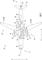
- FIG. 1 provides a schematic top view of an aircraft 10 as may incorporate various embodiments of the present disclosure.
- the aircraft 10 defines a longitudinal direction L and a transverse direction T.
- the aircraft 10 also defines a longitudinal centerline 12 that extends therethrough along the longitudinal direction L.
- the aircraft 10 extends between a forward end 14 and an aft end 16 along the longitudinal direction L.
- the aircraft 10 includes a fuselage 20 and a pair of wings 22, including a first wing 22A and a second wing 22B.
- the first wing 22A extends outward from the fuselage 20 generally along the transverse direction T, from a port side 24 of the fuselage 20.
- the second wing 22B similarly extends outward from the fuselage 20 generally along the transverse direction T from a starboard side 26 of the fuselage 20.
- the aircraft 10 further includes a vertical stabilizer 32 and a pair of horizontal stabilizers 36.
- the fuselage 20, wings 22, and stabilizers 32, 36 may together be referred to as a body of the aircraft 10.
- the aircraft 10 of FIG. 1 also includes a propulsion system.
- the propulsion system depicted includes a plurality of aircraft engines, at least one of which is mounted to each of the pair of wings 22A, 22B.
- the plurality of aircraft engines includes a first aircraft engine 44 mounted to the first wing 22A and a second aircraft engine 46 mounted to the second wing 22B.
- the aircraft engines 44, 46 may be configured as turbofan engines suspended beneath the wings 22A, 22B in an under-wing configuration.
- the aircraft engines 44, 46 may be mounted in other locations, such as to the fuselage 20 aft of the wings 22.
- first and/or second aircraft engines 44, 46 may alternatively be configured as turbojet engines, turboshaft engines, turboprop engines, etc.
- the aircraft 10 can have less or more than two aircraft engines.
- the aircraft 10 can include one or more upper level computing devices 40 communicatively coupled with engine controllers of the first and second aircraft engines 44, 46 so as to command a thrust output of the first and second aircraft engines 44, 46.
- the upper level computing devices 40 may receive various sensor inputs that may indicate the operating conditions associated with the aircraft 10, such as the flight phase, altitude, attitude, weather conditions, weight of the aircraft 10, etc.
- the upper level computing devices 40 can be communicatively coupled via a communication network with various processing devices onboard the aircraft 10, such as processors associated with power controllers.
- the aircraft 10 includes an electrical power system 50.
- the electrical power system 50 includes a power bus 52 to which a plurality of electric power sources and a plurality of electric power consumers are electrically coupled.
- the electrical power system 50 includes a first electric machine 54 mechanically coupled with the first aircraft engine 44 (e.g., to a shaft thereof), a second electric machine 56 mechanically coupled with the second aircraft engine 46 (e.g., to a shaft thereof), and an electric energy storage system 58 having one or more batteries, capacitors, etc.
- FIG. 2 provides a schematic, cross-sectional view of the first aircraft engine 44 and depicts the first electric machine 54 mechanically coupled thereto.
- the first aircraft engine 44 defines an axial direction A1 (extending parallel to a longitudinal centerline 101 provided for reference), a radial direction R1, and a circumferential direction (extending about the axial direction A1; not depicted in FIG. 2 ).
- the first aircraft engine 44 includes a fan section 102 and a core turbine engine 104 disposed downstream of the fan section 102.
- the core turbine engine 104 includes an engine cowl 106 that defines an annular core inlet 108.
- the engine cowl 106 encases, in a serial flow relationship, a compressor section including a booster or low pressure (LP) compressor 110 and a high pressure (HP) compressor 112; a combustion section 114; a turbine section including a high pressure (HP) turbine 116 and a low pressure (LP) turbine 118; and a jet exhaust nozzle section 120.
- the compressor section, combustion section 114, turbine section, and jet exhaust nozzle section 120 together define a core air flowpath 121 extending from the annular core inlet 108 through the LP compressor 110, HP compressor 112, combustion section 114, HP turbine 116, LP turbine 118, and jet exhaust nozzle section 120.
- a high pressure (HP) shaft 122 drivingly connects the HP turbine 116 to the HP compressor 112.
- the HP shaft 122 and rotating components of the HP compressor 112 and the HP turbine 116 that are mechanically coupled with the HP shaft 122 collectively form a high pressure spool 160.
- a low pressure (LP) shaft 124 drivingly connects the LP turbine 118 to the LP compressor 110.
- the LP shaft 124 and rotating components of the LP compressor 110 and the LP turbine 118 that are mechanically coupled with the LP shaft 124 collectively form a low pressure spool 180.
- the fan section 102 may include a fixed or variable pitch fan 126 having a plurality of fan blades 128 coupled to a disk 130 in a spaced apart manner. As depicted, the fan blades 128 extend outward from the disk 130 generally along the radial direction R1. For the variable pitch fan 126 of FIG. 2 , each fan blade 128 is rotatable relative to the disk 130 about a pitch axis Px by virtue of the fan blades 128 being mechanically coupled to an actuation member 132 configured to collectively vary the pitch of the fan blades 128 in unison.
- the fan blades 128, disk 130, and actuation member 132 are together rotatable about the longitudinal centerline 12 by the LP spool 180. As noted above, in some embodiments, the fan blades 128 may be fixed and not rotatable about their respective pitch axes. Further, in other embodiments, the LP spool 180 may be mechanically coupled with the fan 126 via a gearbox.
- the disk 130 is covered by a spinner or rotatable front hub 136 aerodynamically contoured to promote an airflow through the plurality of fan blades 128.
- the fan section 102 includes an outer nacelle 138 that circumferentially surrounds the fan 126 and/or at least a portion of the core turbine engine 104.
- the nacelle 138 is supported relative to the core turbine engine 104 by a plurality of circumferentially-spaced outlet guide vanes 140.
- a downstream section 142 of the nacelle 138 extends over an outer portion of the core turbine engine 104 so as to define a bypass passage 144 therebetween.
- the first electric machine 54 is mechanically coupled with the LP spool 180.
- the first electric machine 54 is directly mechanically coupled to the LP shaft 124.
- the first electric machine 54 can be indirectly mechanically coupled to the LP shaft 124, e.g., via a gearbox.
- the first electric machine 54 can be directly or indirectly mechanically coupled to the HP spool 160, such as directly to the HP shaft 122 or indirectly with the HP shaft 122 by way of a gearbox.
- the first electric machine 54 can be directly or indirectly mechanically coupled to the intermediary spool., such as directly or indirectly to an intermediary shaft of the intermediary spool.
- the first electric machine 54 includes a rotor 54A and a stator 54B.
- the rotor 54A is rotatable with the LP shaft 124.
- the stator 54B includes electric current-carrying elements, such as windings or coils. In this manner, electrical power can be transmitted to or from the electric current-carrying elements, and as will be appreciated, electrical energy can be converted into mechanical energy in a motoring mode or mechanical energy can be converted into electrical energy in a generating mode as the rotor 54A rotates relative to the stator 54B.
- the rotor 54A has rotor components for creating a rotor magnetic field in order to couple to the stator magnetic field to enable energy conversion.
- the rotor components of the rotor 54A can be, without limitation, rotor magnets in case of a permanent magnet synchronous machine, a squirrel cage in case of an induction machine, or a field winding in case of a field wound synchronous machine.
- first aircraft engine 44 depicted in FIG. 2 and the first electric machine 54 mechanically coupled thereto are provided for example purposes and are not intended to be limiting.
- the first aircraft engine 44 may have other configurations.
- the first aircraft engine 44 may be configured as a turboprop engine, a turbojet engine, a differently configured turbofan engine, or an unducted turbofan engine (e.g., without the nacelle 138, but including the stationary outlet guide vanes 140).
- the gas turbine engine may be a geared gas turbine engine (e.g., having a reduction gearbox between the LP shaft 124 and fan 126), may have any other suitable number or configuration of shafts/ spools (e.g., may include an intermediate speed shaft/ turbine/ compressor), etc.
- the second electric machine 56 can be configured and mechanically coupled with the second aircraft engine 46 ( FIG. 1 ) in a same or similar manner as the first electric machine 54 is configured and mechanically coupled with the first aircraft engine 44.
- the first electric machine 54, the second electric machine 56, and the electric energy storage system 58 can each act as electric power sources, or in some instances, as electric power consumers.
- the first electric machine 54 and/or the second electric machine 56 can be electric generators configured to be driven by their respective first and second aircraft engines 44, 46 to generate electric power that can be supplied to one or more electric power consumers.
- the first electric machine 54 and/or the second electric machine 56 can be electric motors configured to drive their respective aircraft engines 44, 46, e.g., in a power assist operation.
- the propulsion system can be a hybrid-electric propulsion system.
- the first and/or second electric machines 54, 56 can be combination motor/generators controllable in a generator mode or motor mode.
- the electric energy storage system 58 can be controlled to either provide electric power to one or more electric power consumers or draw electric power, e.g., for charging.
- the electrical power system 50 also includes a plurality of electric loads 70 that consume but do not produce electric power, such as an aircraft air conditioning system, avionics computing devices, aircraft control systems, cabin lights, etc.
- the electrical power system 50 also includes a fuel cell assembly 60 that is a component of an environmental control system assembly 62 (or "ECS assembly 62").
- the fuel cell assembly 60 can provide electrical power to the plurality of electric loads 70 and/or to the first electric machine 54, the second electric machine 56, and/or to the electric energy storage system 58 depending on their configurations or mode of operation.
- the ECS assembly 62 is located generally at a juncture between the first wing 22A and the fuselage 20.
- the ECS assembly 62 may additionally or alternatively be located at other locations within the aircraft 10, such as at a juncture between the second wing 22B and the fuselage 20, at the aft end 16 of the aircraft 10, etc.
- the ECS assembly 62 can include more than one fuel cell assembly, such as two fuel cell assemblies.
- FIG. 3 provides a schematic perspective view of the fuel cell assembly 60 of FIG. 1 .
- the fuel cell assembly 60 includes a fuel cell stack 64.
- the fuel cell stack 64 includes a housing 65 having an outlet side 66 and a side that is opposite to the outlet side 66, a fuel and air inlet side 67 and a side that is opposite to the fuel and air inlet side 67.
- the fuel cell stack 64 can include a plurality of fuel cells 68 that are "stacked," e.g., side-by-side from one end of the fuel cell stack 64 (e.g., fuel and air inlet side 67) to another end of the fuel cell stack 64 (e.g., side 69).
- the outlet side 66 includes a plurality of outlets 80, each from a respective fuel cell 68 of the fuel cell stack 64.
- output products 82 are directed from the outlets 80 out of the housing 65.
- the outlets 80 can include separate fuel outlets (which may be in fluid communication with, e.g., a fuel exhaust line) and air outlets (which may be in fluid communication with e.g., a fuel cell outlet line of a cabin exhaust delivery system).
- the fuel and air inlet side 67 includes one or more fuel inlets 84 and one or more air inlets 86.
- one or more of the inlets 84, 86 can be on another side of the housing 65.
- Each of the one or more fuel inlets 84 can be fluidly coupled with, e.g., a fuel delivery line of a fuel delivery system.
- Each of the one or more air inlets 86 can be fluidly coupled with, e.g., a fuel cell inlet line of an air delivery system.
- FIG. 4 provides a close-up, schematic view of one fuel cell 68 of the fuel cell stack 64 of FIG. 3 .
- the fuel cells 68 of the fuel cell assembly 60 are electro-chemical devices that may convert chemical energy from a fuel into electrical energy through an electro-chemical reaction of the fuel, such as hydrogen, with an oxidizer, such as oxygen contained in the atmospheric air. Accordingly, the fuel cell assembly 60 can advantageously be utilized as a power source.
- the example fuel cell 68 depicted in FIG. 4 and each of the fuel cells 68 of the fuel cell stack 64 of FIG. 3 , are configured as proton exchange membrane fuel cells (“PEM fuel cells”), also known as a polymer electrolyte membrane fuel cell.
- PEM fuel cells have an operating temperature range and operating temperature pressure determined to work well with the conditions associated with aircraft and other vehicles.
- the fuel cell 68 includes a cathode side 88, an anode side 90, and an electrolyte layer 92 positioned between the cathode side 88 and the anode side 90.
- the cathode side 88 can include a cathode 89 and the anode side 90 can include an anode 91.
- the cathode side 88 includes a cathode inlet 93 and a cathode outlet 94 and the anode side 90 includes an anode inlet 95 and an anode outlet 96.
- the cathode side 88 of the fuel cell 68 can be in fluid communication with, e.g., a cabin exhaust delivery system, and more specifically, a fuel cell inlet line of the cabin exhaust delivery system.
- the cathode outlet 94 is in fluid communication with a fuel cell outlet line of the cabin exhaust delivery system.
- the anode side 90 of the fuel cell 68 and more specifically, the anode inlet 95 of the anode side 90, is in fluid communication with, e.g., a fuel delivery line of a fuel delivery system.
- the anode outlet 96 is in fluid communication with e.g., a fuel exhaust line of the fuel delivery system. Accordingly, air may pass through the cathode side 88 and fuel may pass through the anode side 90.
- the electrical power system 50 includes a plurality of power controllers.
- Each power controller can include one or more processors and one or more non-transitory memory devices, e.g., embodied in a controller, and power electronics to convert electrical power, e.g., from alternating current (AC) to direct current (DC) or vice versa, or to condition the electrical power to a desired voltage, current, or both.
- AC alternating current
- DC direct current
- the first electric machine 54 has an associated power controller 55 that controls the electric power between the first electric machine 54 and the power bus 52.
- the second electric machine 56 has an associated power controller 57 that controls the electric power between the second electric machine 56 and the power bus 52.
- the electric energy storage system 58 also has an associated power controller 59 that controls the electric power between the electric energy storage system 58 and the power bus 52.
- the fuel cell assembly 60 has an associated power controller 61 that controls the electric power between the fuel cell assembly 60 and the power bus 52.
- power controllers 71 can be arranged to control the electric power provided from the power bus 52 to the power consuming one or more electric loads 70.
- the electrical power system 50 is configured as a decentralized power allocation system. That is, the architecture of the electrical power system 50 enables the power controllers to control the electrical power outputs of their respective power sources to meet the power demands of the power consumers collaboratively, adaptively, and without active supervision, e.g., from a supervisor controller.
- Decentralized control of electric power transmission from power sources to one or more power consumers can provide certain advantages, benefits, and technical effects.
- the decentralized electrical power allocation systems provided herein may address the drawbacks of conventional centralized power allocation systems and offer collaborative and adaptive control of the power outputs of the power sources to meet a power demand on a power bus applied by the one or more power consumers.
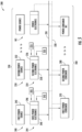
- FIG. 5 provides a system diagram of an electrical power system 200 according to an example embodiment of the present disclosure.
- the electrical power system 200 is configured as a decentralized power allocation system in FIG. 5 .
- the electrical power system 200 can be implemented in a vehicle, such as the aircraft 10 of FIG. 1 , ships, trains, unmanned aerial vehicles, automobiles, etc.
- the electrical power system 200 includes a direct current power bus (or DC power bus 210), a plurality of power source assemblies 230 electrically coupled with the DC power bus 210, and one or more electric power consumers 260 electrically coupled with the DC power bus 210.
- the electrical power system 200 further includes a communication bus 220 (shown in dashed lines in FIG. 5 ), which may include one or more wired or wireless communication links.
- the communication bus 220 enables communication between various components of the electrical power system 200.
- the plurality of power source assemblies 230 include a first power source assembly 240 and a second power source assembly 250.
- Each power source assembly includes an electric power source and a power controller.
- the first power source assembly 240 has a first power source 242 and a first power controller 244.
- the second power source assembly 250 has a second power source 252 and a second power controller 254.
- the first power source 242 is a fuel cell and the second power source 252 is an electric machine configured as an electric generator or operable in a generator mode.
- the plurality of power source assemblies 230 can include more than two (2) power source assemblies in other example embodiments, or N-S number of power source assemblies, wherein N-S is an integer equal to or greater than two (2).
- the first power source 242 and the second power source 252 are electrically coupled with the DC power bus 210.
- the first power controller 244 controls electric power provided from the first power source 242 to the DC power bus 210.
- the second power controller 254 controls electric power provided from the second power source 252 to the DC power bus 210.
- the first power controller 244 and the second power controller 254 each include one or more processors and one or more non-transitory memory devices embodied in a first controller 246 and a second controller 256, respectively.
- the first power controller 244 includes first power electronics 248 to convert or condition electrical power provided from the first power source 242 to the DC power bus 210.
- the first power electronics 248 can include a plurality of switches controllable in a switching scheme, for example.
- the second power controller 254 includes second power electronics 258 to convert or condition electrical power provided from the second power source 252 to the DC power bus 210.
- the second power electronics 258 can include a plurality of switches controllable in a switching scheme, for example.
- the first controller 246 and the second controller 256 are communicatively coupled with one another (and to other components) via the communication bus 220.
- the one or more electric power consumers 260 include a first power consumer 270 and a second power consumer 280 in this example embodiment.
- the first power consumer 270 can represent one or more mission critical or essential loads and the second power consumer 280 can represent one or more non-essential loads.
- the one or more electric power consumers 260, or sensors or communication interfaces thereof, can be communicatively coupled with the first controller 246 and the second controller 256 of the first and second power source assemblies 240, 250 via the communication bus 220.
- the one or more electric power consumers 260 can include one or more power consumers, or N-C number of power consumer assemblies, wherein N-C is an integer equal to or greater than one (1).
- the first power consumer 270 and the second power consumer 280 are both directly electrically coupled with the DC power bus 210.
- the first power consumer 270 and/or the second power consumer 280 can be indirectly electrically coupled with the DC power bus 210.
- an intermediate power bus and/or other power electronics can be positioned electrically between the DC power bus 210 and the first power consumer 270 and/or the second power consumer 280.
- FIG. 6 provides a logic flow diagram for allocating power to be output by the first power source 242 to meet the power demand on the DC power bus 210.
- FIG. 7 provides a logic flow diagram for allocating power to be output by the second power source 252 to meet the power demand on the DC power bus 210.
- the first controller 246 includes adaptive droop control logic 300 in accordance with an adaptive droop control scheme.
- the one or more processors of the first controller 246 can regulate the power output of the first power source 242, which as noted above, is a fuel cell in this example embodiment (hence the "FC" designations in FIG. 6 ).
- a power feedback P fbk-FC is input into a droop control block 304.
- the power feedback P fbk-FC can be a measured, calculated, or predicted value indicating the power output of the first power source 242.
- one or more sensors can sense the voltage, frequency, and/or the electric current proximate the first power source 242 to measure, calculate, or predict the power output of the first power source 242.
- the power feedback P fbk-FC is used for correlation purposes.
- the power feedback P fbk-FC can be correlated with a first droop function f drp-Fc associated with the first power source 242 to determine a voltage setpoint v REF-FC .
- the voltage setpoint v REF-FC can be determined as the y-component of the point along the first droop function f drp-FC that corresponds with the power feedback P fbk-FC .
- the first droop function f drp-FC or curve represents an efficiency of the first power source 242 to generate electrical power for a given power output of the first power source 242.
- the first droop function f drp-Fc used for the correlation can be selected from a plurality of first droop functions associated with the first power source 242 as represented in FIG. 6 .
- the first droop function f drp-Fc used for correlation purposes can be selected based at least in part on one or more operating conditions 243 ( FIG. 5 ) associated with the vehicle in which the electrical power system 200 is implemented.
- the first droop function f drp-FC can be selected based on a phase of flight, an altitude of the aircraft, a number of passengers onboard the aircraft, weather conditions, a combination of the foregoing, etc. These noted operating conditions may each affect the power demand on the DC power bus 210.
- the plurality of first droop functions can include a first droop function for each phase of flight, such as one for takeoff, one for climb, one for cruise, one for descent, and one for approach and landing.
- the plurality of first droop functions can include a first droop function for different altitude ranges, such as one for zero (0) to ten thousand (10,000) feet, one for ten thousand one (10,001) to twenty thousand (20,000) feet, and one for twenty thousand one (20,001) feet and above.
- the altitude ranges can be defined with respect to feet above sea level or above ground level.
- the plurality of first droop functions can include a first droop function for different ranges of passengers onboard, such as one first droop function for a first range of passengers (e.g., 0 to 50 passengers), one for a second range of passengers (e.g., 51 to 100 passengers), and one for a third range of passengers (e.g., 101 passengers and up).
- the plurality of first droop functions selectable for correlation purposes can each have different slopes and/or different y-intercepts.
- the first droop functions or curves each represent an efficiency of the first power source 242 to generate electrical power for a given power output of the first power source 242 at a given set of operating conditions.
- the selected first droop function f drp-FC can be used to schedule or determine the voltage setpoint v REF-FC associated with the first power source 242. More specifically, the voltage setpoint v REF-FC can be determined as the y-component of the point along the first droop function f drp-FC that corresponds with the power feedback P fbk-FC . In this regard, the voltage setpoint v REF-FC is set as a function of the power feedback P fbk-FC .
- the y-intercept of the first droop function f drp-Fc selected for correlation purposes in FIG. 6 is denoted as v SET-FC .
- the determined voltage setpoint v REF-FC is output from the droop control block 304 and forwarded to a voltage loop of the adaptive droop control logic 300.
- the voltage setpoint v REF-FC is input into a first summation block 306 and compared to a voltage feedback v fbk-FC .
- the voltage feedback v fbk-FC can be a measured, calculated, or predicted value indicating the voltage at the first power source 242, e.g., at output terminals thereof.
- a voltage difference v ⁇ -FC is determined at the first summation block 306, e.g., by subtracting the voltage setpoint v REF-FC from the voltage feedback v fbk-FC or vice versa.
- the voltage difference v ⁇ -FC is then input into a proportional-integral control 308, which generates one or more outputs that can be input into a switching logic control 310 that controls modulation of switching devices of the first power electronics 248, e.g., in a Pulse Width Modulated (PWM) switching scheme.
- PWM Pulse Width Modulated
- the second controller 256 includes adaptive droop control logic 400 in accordance with the adaptive droop control scheme.
- the one or more processors of the second controller 256 can regulate the power output of the second power source 252, which as noted above, is an electric generator or electric machine operable in a generator mode in this example embodiment (hence the GEN" designations in FIG. 7 ).
- a power feedback P fbk-GEN is input into a droop control block 304.
- the power feedback P fbk-GEN can be a measured, calculated, or predicted value indicating the power output of the second power source 252.
- one or more sensors can sense the voltage, frequency, and/or the electric current proximate the second power source 252 to measure, calculate, or predict the power output of the second power source 252.
- the power feedback P fbk-GEN is used for correlation purposes.
- the power feedback P fbk-GEN can be correlated with a second droop function f drp-GEN associated with the second power source 252 to determine a voltage setpoint v REF-GEN .
- the voltage setpoint v REF-GEN can be determined as the y-component of the point along the second droop function f drp-GEN that corresponds with the power feedback P fbk-GEN.
- the second droop function f drp-GEN or curve represents an efficiency of the second power source 252 to generate electrical power for a given power output of the second power source 252.
- the second droop function f drp-GEN used for the correlation can be selected from a plurality of second droop functions associated with the second power source 252 as represented in FIG. 7 .
- the second droop function f drp-GEN used for correlation purposes can be selected based at least in part on one or more operating conditions 253 ( FIG. 5 ) associated with the vehicle in which the electrical power system 200 is implemented.
- the second droop function f drp-GEN can be selected based on a phase of flight, an altitude of the aircraft, a number of passengers onboard the aircraft, weather conditions, a combination of the foregoing, etc. These noted operating conditions may each affect the power demand on the DC power bus 210.
- the one or more operating conditions 253 received by the second controller 256 of FIG. 5 can be the same as the one or more operating conditions 243 received by the first controller 246 of FIG. 5 .
- the plurality of second droop functions selectable for correlation purposes can each have different slopes and/or different y-intercepts.
- the second droop functions or curves each represent an efficiency of the second power source 252 to generate electrical power for a given power output of the second power source 252 at a given set of operating conditions.
- the selected first droop function f drp-GEN can be used to schedule or determine the voltage setpoint v REF-GEN associated with the second power source 252. More particularly, the voltage setpoint v REF-GEN can be determined as the y-component of the point along the second droop function f drp-GEN that corresponds with the power feedback P fbk-GEN . In this regard, the voltage setpoint v REF-GEN is set as a function of the power feedback P fbk-GEN .
- the y-intercept of the second droop function f drp-GEN selected for correlation purposes in FIG. 7 is denoted as v SET-GEN .
- the voltage setpoint v REF-GEN is output from the droop control block 404 and forwarded to a voltage loop of the adaptive droop control logic 400.
- the voltage setpoint v REF-GEN is input into a first summation block 406 and compared to a voltage feedback v fbk-GEN .
- the voltage feedback v fbk-GEN can be a measured, calculated, or predicted value indicating the voltage at the second power source 252, e.g., at output terminals thereof.
- a voltage difference v ⁇ -GEN is determined at the first summation block 406, e.g., by subtracting the voltage setpoint v REF-GEN from the voltage feedback v fbk-GEN or vice versa.
- the voltage difference v ⁇ -GEN is then input into a proportional-integral control 408, which generates one or more outputs that can be input into a switching logic control 410 that controls modulation of switching devices of the second power electronics 258, e.g., in a PWM switching scheme. Accordingly, a power output 412 of the second power source 252 is achieved.
- the power output 412 is affected by a disturbance, which is the power demand 212 on the DC power bus 210, as represented at a second summation block 414.
- each power controller of the power source assemblies 230 includes executable adaptive droop control logic, e.g., similar to the adaptive droop control logic 300, 400 depicted in FIGS. 6 and 7 .
- the one or more processors of the given power controller cause its associated power electronics to control the power output of its associated power source.
- This adaptive droop control scheme executed by each power controller of the power source assemblies 230 enables intelligent decentralized power allocation for meeting power demands on the DC power bus 210 applied by the electric power consumers 260.
- implementation of the adaptive droop control scheme enables decentralized DC bus regulation according to the efficiencies of the power sources at given power outputs.
- FIG. 8 provides a graph representing the first droop function f drp-FC associated with the first power source 242 overlaid with the second droop function f drp-GEN associated with the second power source 252 on a DC bus voltage versus power output graph.
- the first droop function f drp-FC represents an efficiency of the first power source 242 to generate electrical power for a given power output of the first power source 242
- the second droop function f drp-GEN represents an efficiency of the second power source 252 to generate electrical power for a given power output of the second power source 252.
- the droop functions are also functions of power output efficiency ⁇ .
- the droop functions have different slopes and different y-intercepts, with the first droop function f drp-FC having a steeper slope than the second droop function f drp-GEN and the first droop function f drp-Fc having a greater y-intercept than the second droop function f drp-GEN .
- the droop functions intersect at a point P Int corresponding to a reference power level P RF . Accordingly, the first power source 242, or fuel cell for this example, is more efficient at outputting electric power at lower power levels than the second power source 252, or electric machine in this example.
- the second power source 252 is more efficient at outputting electric power than the first power source 242.
- the droop functions are coordinated so that the power output of the first power source 242, or fuel cell, is greater than the power output of the second power source 252, or electric machine, at power levels less than the reference power level P RF and so that the power output of the second power source 252, or electric machine, is greater than the power output of the first power source 242, or fuel cell, at power levels greater than the reference power level P RF .
- the working point of both the first power source 242 and the second power source 252 will both be on the same horizontal line as the first and second power sources 242, 252 are electrically coupled to a common power bus, or DC power bus 210 in this example.
- a common power bus or DC power bus 210 in this example.
- the working point of the first power source 242 is denoted as PT1-FC and the working point of the second power source 252 is denoted as PT1-GEN.
- the first DC bus voltage v DC BUS 1 the first power source 242, or fuel cell, has a power output of P1 while the second power source 252, or electric machine, has a power output of P0.
- the first power source 242 has a greater load share or power output at the first DC bus voltage v DC BUS 1 than does the second power source 252.
- the power output of P0 is equal to zero (0) in this instance, as the y-intercept of the second droop function f drp-GEN is less than the first DC bus voltage v DC BUS 1 . Accordingly, to meet the first DC bus voltage v DC BUS 1 , only the first power source 242, or fuel cell, outputs electric power. Thus, the load share split is 100%/0%, with the first power source 242 being at 100% and the second power source 252 at 0%.
- the adaptive droop control scheme allows for the first power source 242, or fuel cell, to handle all or most of the relatively low power demand on the DC power bus 210.
- This takes advantage of the physics and characteristics of the fuel cell to operate at high efficiency at low power levels whilst also saving fuel and wear on the electric machine and gas turbine engine to which the electric machine is coupled.
- a second DC bus voltage v DC BUS 2 which corresponds to a lower voltage level than the first DC bus voltage v DC BUS 1
- the working point of the first power source 242, or fuel cell, and the working point of the second power source 252, or electric machine are on the same horizontal line.
- the working point of the first power source 242 is denoted as PT2-FC and the working point of the second power source 252 is denoted as PT2-GEN.
- the first power source 242, or fuel cell, and the second power source 252, or electric machine both have the same power output, which corresponds to the reference power level P RF .
- the first power source 242 and the second power source 252 have a same load share or power output at the second DC bus voltage v DC BUS 2 .
- the load share split is 50%/50%, with the first power source 242 being at 50% and the second power source 252 being at 50% to meet the power demand on the DC power bus 210.
- a third DC bus voltage v DC BUS 3 which corresponds to a lower voltage level than the second DC bus voltage v DC BUS 2
- the working point of the first power source 242, or fuel cell, and the working point of the second power source 252, or electric machine are on the same horizontal line.
- the working point of the first power source 242 is denoted as PT3-FC and the working point of the second power source 252 is denoted as PT3-GEN.
- the first power source 242, or fuel cell has a power output of P2 while the second power source 252, or electric machine, has a power output of P3, which is greater than the power output of P2.
- the second power source 252 has a greater load share or power output at the third DC bus voltage v DC BUS 3 than does the first power source 242.
- the load share split can be 40%/60%, with the first power source 242 being at 40% and the second power source 252 at 60%, for example.
- the adaptive droop control scheme allows for the second power source 252, or electric machine mechanically coupled with a gas turbine engine, to handle most of the relatively high power demand on the DC power bus 210. This takes advantage of the physics and characteristics of the electric machine to operate at high efficiency at high power levels whilst also using the fuel cell in part to meet the power demand on the DC power bus 210.
- the power allocation for the power sources is set according to the characteristics of the droop functions, such as their slopes, y-intercepts, and overall shapes.
- the load share between the first power source 242 and the second power source 252 becomes more balanced, as represented at the second DC bus voltage v DC BUS 2 .
- the load share between the first power source 242 and the second power source 252 becomes less balanced, as represented at the first DC bus voltage v DC BUS 1 and the third DC bus voltage v DC BUS 3 .
- FIGS. 6, 7 , and 8 are linear functions. However, one or more of the droop functions can be non-linear functions in other example embodiments.
- FIG. 9 provides a graph representing a non-linear first droop function f drp-Fc associated with the first power source 242 overlaid with the second droop function f drp-GEN associated with the second power source 252 on a DC bus voltage versus power output graph.
- the non-linear first droop function f drp-FC may better represent the efficiency of the first power source 242, or fuel cell, to output electric power at a given power output.
- the second droop function f drp-GEN may be linear, but may be a piecewise linear function.
- the piecewise linear second droop function f drp-GEN includes a first segment having a first slope and a second segment having a second slope that is different than the first slope.
- the first segment is steeper than the second segment of the second droop function f drp-GEN .
- Such a piecewise linear second droop function f drp-GEN having various slopes may better represent the efficiency of the second power source 252, or electric machine, to output electric power at a given power output.
- the droop functions can have other curves or shapes as well, such as polynomial shapes.
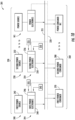
- FIG. 10 provides a system diagram of an electrical power system 201 according to another example embodiment of the present disclosure.
- the electrical power system 201 is configured as a decentralized power allocation system in FIG. 10 .
- the electrical power system 201 of FIG. 10 can be implemented in a vehicle, such as the aircraft 10 of FIG. 1 , ships, trains, unmanned aerial vehicles, automobiles, etc.
- the electrical power system 201 of FIG. 10 is configured in a similar manner as the electrical power system 200 of FIG. 5 , and therefore, like parts will be identified with like numerals with it being understood that the description of the like parts of the electrical power system 200 applies to the electrical power system 201 unless otherwise noted.
- the electrical power system 201 of FIG. 10 includes an alternating current power bus (or AC power bus 215) to which the plurality of power source assemblies 230 and the one or more electric power consumers 260 are electrically coupled. Single or multiphase power can be transmitted along the AC power bus 215.
- the first power consumer 270 and the second power consumer 280 are both directly electrically coupled with the AC power bus 215.
- the first power consumer 270 and/or the second power consumer 280 can be indirectly electrically coupled with the AC power bus 215.
- an intermediate power bus and/or other power electronics can be positioned electrically between the AC power bus 215 and the first power consumer 270 and/or the second power consumer 280.
- a sinusoidal voltage waveform on an AC power bus has both a frequency and an amplitude.
- the frequency of a voltage waveform is highly coupled with active power, or power that is utilized and consumed for useful work in electrical systems.
- the amplitude of a voltage waveform is highly coupled with reactive power, or power that "bounces" back and forth between the power source(s) and power consumer(s) in electrical systems. Accordingly, active power is more sensitive to changes in frequency on the AC power bus 215 while reactive power is more sensitive to changes in amplitude.
- FIG. 11 provides a logic flow diagram for allocating power to be output by the first power source 242, or fuel cell, to meet the power demand on the AC power bus 215.
- FIG. 12 provides a logic flow diagram for allocating power to be output by the second power source 252, or electric machine, to meet the power demand on the AC power bus 215.
- the first controller 246 includes adaptive droop control logic 800 in accordance with an adaptive droop control scheme for AC power bus systems.
- the one or more processors of the first controller 246 can regulate the power output of the first power source 242, which as noted above, is a fuel cell in this example embodiment (hence the "FC" designations in FIG. 11 ).
- the adaptive droop control logic 800 includes active power droop control.
- a power feedback P fbk-FC which relates to active power, is input into an active power droop control block 804.
- the power feedback P fbk-FC can be a measured, calculated, or predicted value indicating the active power output of the first power source 242.
- one or more sensors can sense the voltage, frequency, and/or the electric current proximate the first power source 242 to measure, calculate, or predict the active power output of the first power source 242.
- the power feedback P fbk-FC is used for correlation purposes.
- the power feedback P fbk-FC can be correlated with a first active droop function f drp-FC-A associated with the first power source 242 to determine a frequency setpoint F REF-FC .
- the first active droop function f drp-FC-A used for the correlation can be selected from a plurality of first active droop functions associated with the first power source 242.
- the first active droop function f drp-FC-A can be selected based at least in part on one or more operating conditions 243 ( FIG. 10 ) associated with the vehicle in which the electrical power system 201 is implemented.
- the first active droop function f drp-FC-A can be selected based on a phase of flight, altitude of the aircraft, number of passengers onboard the aircraft, weather conditions, a combination of the foregoing, etc.
- the first droop functions or curves represent an efficiency of the first power source 242 to generate electrical power for a given power output of the first power source 242 at a given set of operating conditions.
- the selected first active droop function f drp-FC-A can be used to schedule or determine the frequency setpoint f REF-FC associated with the first power source 242. More particularly, the frequency setpoint f REF-FC can be determined as the y-component of the point along the first active droop function f drp-FC-A that corresponds with the power feedback P fbk-FC . In this regard, the frequency setpoint f REF-FC is set as a function of the power feedback P fbk-FC .
- the y-intercept of the first active droop function f drp-FC-A selected for correlation purposes in FIG. 11 is denoted as f SET-FC .
- the frequency setpoint f REF-FC is output from the droop control block 804 and input into a first summation block 806 and compared to a frequency feedback f fbk-FC .
- the frequency feedback f fbk-FC can be a measured, calculated, or predicted value indicating the frequency at the first power source 242, e.g., at output terminals thereof.
- a frequency difference f ⁇ -FC is determined at the first summation block 806, e.g., by subtracting the frequency setpoint f REF-FC from the frequency feedback f fbk-FC or vice versa.
- the adaptive droop control logic 800 includes reactive power droop control in addition to the active power droop control disclosed above.
- a power feedback Q fbk-FC which relates to reactive power, is input into a reactive power droop control block 818.
- the power feedback Q fbk-FC can be a measured, calculated, or predicted value indicating the reactive power at the first power source 242, or rather the power that moves back and forth between the first power source 242 and the one or more electric power consumers 260.
- a varmeter can be used to measure, calculate, or predict the reactive power at the first power source 242.
- the power feedback Q fbk-FC is used for correlation purposes. Specifically, the power feedback Q fbk-FC can be correlated with a first reactive droop function f drp-FC-R associated with the first power source 242 to determine a voltage amplitude setpoint v REF_AC-FC .
- the first reactive droop function f drp-FC-R used for the correlation can be selected from a plurality of first reactive droop functions associated with the first power source 242.
- the first reactive droop function f drp-FC-R can be selected based at least in part on one or more operating conditions 243 ( FIG. 10 ) associated with the vehicle in which the electrical power system 201 is implemented.
- the first reactive droop function f drp-FC-R can be selected based on a phase of flight, altitude of the aircraft, number of passengers onboard the aircraft, weather conditions, a combination of the foregoing, etc.
- the selected first reactive droop function f drp-FC-R can be used to schedule or determine the voltage amplitude setpoint v REF_AC-FC associated with the first power source 242. More particularly, the voltage amplitude setpoint v REF_AC-FC can be determined as the y-component of the point along the first reactive droop function f drp-FC-R that corresponds with the power feedback Q fbk-FC . In this regard, the voltage amplitude setpoint v REF_AC-FC is set as a function of the power feedback Q fbk-FC , which corresponds to reactive power feedback.
- the y-intercept of the first reactive droop function f drp-FC-R selected for correlation purposes in FIG. 11 is denoted as v SET-FC .
- the power feedback Q fbk-FC is bound by an inductive limit -Q Max and a capacitive limit Q Max .
- the voltage amplitude setpoint v REF_AC-FC is output from the reactive power droop control block 818 and input into a second summation block 820.
- the voltage amplitude setpoint v REF_AC-FC is compared to a voltage amplitude feedback f fbk _ AC-FC at the second summation block 820.
- the voltage amplitude feedback f fbk _ AC-FC can be a measured, calculated, or predicted value indicating the voltage amplitude at the first power source 242, e.g., at output terminals thereof.
- a voltage amplitude difference v ⁇ -FC is determined at the second summation block 820, e.g., by subtracting the voltage amplitude setpoint v REF_AC-FC from the voltage amplitude feedback f fbk_AC-FC or vice versa.
- the frequency difference f ⁇ - FC and the voltage amplitude difference v ⁇ - FC are input into a voltage synthesizer 808, which generates one or more outputs (e.g., a modulation index) that can be input into a switching logic control 810 that controls modulation of switching devices of the first power electronics 248, e.g., in a PWM switching scheme. Accordingly, a power output 812 of the first power source 242 is achieved.
- the power output 812 has an active power component and a reactive power component.
- the power output 812 is affected by a disturbance, which is a power demand 217 on the AC power bus 215, as represented at a third summation block 814.
- the second controller 256 includes adaptive droop control logic 900 in accordance with the adaptive droop control scheme.
- the one or more processors of the second controller 256 can regulate the power output of the second power source 252, which as noted above, is an electric generator or electric machine operable in a generator mode in this example embodiment (hence the GEN" designations in FIG. 12 ).
- the adaptive droop control logic 900 associated with the second power source assembly 250 includes both active power droop control and reactive droop control.
- a power feedback P fbk-GEN which relates to active power, is input into an active power droop control block 904.
- the power feedback P fbk-GEN can be a measured, calculated, or predicted value indicating the active power output of the second power source 252.
- one or more sensors can sense the voltage, frequency, and/or the electric current proximate the second power source 252 to measure, calculate, or predict the active power output of the second power source 252.
- the power feedback P fbk-GEN is used for correlation purposes. Specifically, the power feedback P fbk-GEN can be correlated with a second active droop function f drp-GEN-A associated with the second power source 252 to determine a frequency setpoint f REF-GEN .
- the second active droop function f drp-GEN-A used for the correlation can be selected from a plurality of second active droop functions associated with the second power source 252.
- the second active droop function f drp-GEN-A can be selected based at least in part on one or more operating conditions 253 ( FIG. 10 ) associated with the vehicle in which the electrical power system 201 is implemented.
- the second active droop function f drp-GEN-A can be selected based on a phase of flight, altitude of the aircraft, number of passengers onboard the aircraft, weather conditions, a combination of the foregoing, etc.
- the second droop functions or curves represent an efficiency of the second power source 252 to generate electrical power for a given power output of the second power source 252.
- the one or more operating conditions 253 received by the second controller 256 of FIG. 10 can be the same as the one or more operating conditions 243 received by the first controller 246 of FIG. 10 .
- the selected second active droop function f drp-GEN-A can be used to schedule or determine the frequency setpoint f REF-GEN associated with the second power source 252. More particularly, the frequency setpoint f REF-GEN can be determined as the y-component of the point along the second active droop function f drp-GEN-A that corresponds with the power feedback P fbk-GEN . In this regard, the frequency setpoint f REF-GEN is set as a function of the power feedback P fbk-GEN .
- the y-intercept of the second active droop function f drp-GEN-A selected for correlation purposes in FIG. 12 is denoted as f SET-GEN .
- the frequency setpoint f REF-GEN is output from the droop control block 904 and input into a first summation block 906 and compared to a frequency feedback f fbk-GEN .
- the frequency feedback f fbk-GEN can be a measured, calculated, or predicted value indicating the frequency at the second power source 252, e.g., at output terminals thereof.
- a frequency difference f ⁇ -GEN is determined at the first summation block 906, e.g., by subtracting the frequency setpoint f REF-GEN from the frequency feedback f fbk-GEN or vice versa.
- the adaptive droop control logic 900 includes reactive power droop control in addition to the active power droop control disclosed above.
- a power feedback Q fbk-GEN which relates to reactive power, is input into a reactive power droop control block 918.
- the power feedback Q fbk-GEN can be a measured, calculated, or predicted value indicating the reactive power at the second power source 252, or rather the power that moves back and forth between the second power source 252 and the one or more electric power consumers 260.
- a varmeter can be used to measure, calculate, or predict the reactive power at the second power source 252.
- the power feedback Q fbk-GEN is used for correlation purposes.
- the power feedback Q fbk-GEN can be correlated with a second reactive droop function f drp-GEN-R associated with the second power source 252 to determine a voltage amplitude setpoint v REF_AC-GEN .
- the second reactive droop function f drp-GEN-R used for the correlation can be selected from a plurality of second reactive droop functions associated with the second power source 252.
- the second reactive droop function f drp-GEN-R can be selected based at least in part on one or more operating conditions 253 ( FIG. 10 ) associated with the vehicle in which the electrical power system 201 is implemented.
- the second reactive droop function f drp-GEN-R can be selected based on a phase of flight, altitude of the aircraft, number of passengers onboard the aircraft, weather conditions, a combination of the foregoing, etc.
- the selected second reactive droop function f drp-GEN-R can be used to schedule or determine the voltage amplitude setpoint v REF_AC-GEN associated with the second power source 252. More specifically, the voltage amplitude setpoint v REF_ _ AC-GEN can be determined as the y-component of the point along the second reactive droop function f drp-GEN-R that corresponds with the power feedback Q fbk-GEN . In this regard, the voltage amplitude setpoint v REF_AC-GEN is set as a function of the power feedback Q fbk-GEN, which corresponds to reactive power feedback.
- the y-intercept of the second reactive droop function f drp-GEN-R selected for correlation purposes in FIG. 12 is denoted as v SET-GEN .
- the power feedback Q fbk-GEN is bound by an inductive limit -Q Max and a capacitive limit Q Max .
- the voltage amplitude setpoint v REF_AC-GEN is output from the reactive droop control block 918 and input into a second summation block 920.
- the voltage amplitude setpoint v REF_AC-GEN is compared to a voltage amplitude feedback f fbk _ AC-GEN at the second summation block 920.
- the voltage amplitude feedback f fbk _ AC-GEN can be a measured, calculated, or predicted value indicating the voltage amplitude at the second power source 252, e.g., at output terminals thereof.
- a voltage amplitude difference v ⁇ -GEN is determined at the second summation block 920, e.g., by subtracting the voltage amplitude setpoint v REF_AC-GEN from the voltage amplitude feedback f fbk_AC-GEN or vice versa.
- the frequency difference f ⁇ -GEN and the voltage amplitude difference v ⁇ -GEN are input into a voltage synthesizer 908, which generates one or more outputs (e.g., a modulation index) that can be input into a switching logic control 910 that controls modulation of switching devices of the second power electronics 258, e.g., in a PWM switching scheme. Accordingly, a power output 912 of the second power source 252 is achieved.
- the power output 912 has an active power component and a reactive power component.
- the power output 912 is affected by a disturbance, which is the power demand 217 on the AC power bus 215, as represented at a third summation block 914.
- the frequency difference f ⁇ -GEN and the voltage amplitude difference v ⁇ -GEN are each input into respective proportional-integral controls and then fed into the switching logic control 910.
- each power controller of the power source assemblies 230 includes executable adaptive droop control logic, e.g., similar to the adaptive droop control logic 800, 900 depicted in FIGS. 11 and 12 .
- the one or more processors of the given power controller cause its associated power electronics to control the power output of its associated power source.
- This adaptive droop control scheme executed by each power controller of the power source assemblies 230 enables intelligent decentralized power allocation for meeting power demands on the AC power bus 215 applied by the electric power consumers 260.
- implementation of the adaptive droop control scheme enables decentralized AC bus regulation according to the efficiencies of the power sources at given power outputs.
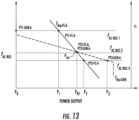
- FIG. 13 provides a graph representing the first droop function f drp-FC-A associated with the first power source 242 overlaid with the second droop function f drp-GEN-A associated with the second power source 252 on an AC bus frequency versus power output graph.
- the first droop function f drp-FC-A represents an efficiency of the first power source 242 to generate active electrical power for a given power output of the first power source 242
- the second droop function f drp-GEN-A represents an efficiency of the second power source 252 to generate active electrical power for a given power output of the second power source 252.
- the droop functions are also functions of power output efficiency ⁇ .
- the active power droop functions have different slopes, with the first droop function f drp-FC-A having a steeper slope than the second droop function f drp-GEN-A . Also, the droop functions intersect at a point P Int corresponding to a reference power level P RF .
- the first power source 242, or fuel cell for this example is more efficient at outputting electric power at lower power levels than the second power source 252, or electric machine in this example. In contrast, at higher power levels, the second power source 252 is more efficient at outputting electric power than the first power source 242.
- the droop functions are coordinated so that the power output of the first power source 242, or fuel cell, is greater than the power output of the second power source 252, or electric machine, at power levels less than the reference power level and so that the power output of the second power source 252, or electric machine, is greater than the power output of the first power source 242, or fuel cell, at power levels greater than the reference power level P RF .
- the working point of both the first power source 242 and the second power source 252 will both be on the same horizontal line as the first and second power sources 242, 252 are electrically coupled to a common power bus, or AC power bus 215 in this example.
- a common power bus or AC power bus 215 in this example.
- the working point of the first power source 242 is denoted as PT1-FC-A and the working point of the second power source 252 is denoted as PT1-GEN-A.
- the first power source 242, or fuel cell has a power output of P1 while the second power source 252, or electric machine, has a power output of P0.
- the first power source 242 has a greater load share or power output at the first AC bus frequency f AC BUS 1 than does the second power source 252.
- the power output of P0 is equal to zero (0) in this instance, as the y-intercept of the second droop function f drp-GEN-A is less than the first AC bus frequency f AC BUS 1 . Accordingly, to meet the first AC bus frequency f AC BUS 1 , only the first power source 242, or fuel cell, outputs electric power. Thus, the load share split is 100%/0%, with the first power source 242 being at 100% and the second power source 252 at 0%.
- the adaptive droop control scheme allows for the first power source 242, or fuel cell, to handle all or most of the relatively low power demand on the AC power bus 215. This takes advantage of the physics and characteristics of the fuel cell to operate at high efficiency at low power levels whilst also saving fuel and wear on the electric machine and gas turbine engine to which the electric machine is coupled.
- a second AC bus frequency f AC BUS 2 which corresponds to a lower frequency level than the first AC bus frequency f AC BUS 2
- the working point of the first power source 242, or fuel cell, and the working point of the second power source 252, or electric machine are on the same horizontal line.
- the working point of the first power source 242 is denoted as PT2-FC-A and the working point of the second power source 252 is denoted as PT2-GEN-A.
- the first power source 242, or fuel cell, and the second power source 252, or electric machine both have the same power output, which corresponds to the reference power level P RF .
- the first power source 242 and the second power source 252 have a same load share or power output at the second AC bus frequency f AC BUS 2 .
- the load share split is 50%/50%, with the first power source 242 being at 50% and the second power source 252 being at 50% to meet the power demand on the AC power bus 215.
- a third AC bus frequency f AC BUS 3 which corresponds to a lower frequency level than the second AC bus frequency f AC BUS 2
- the working point of the first power source 242, or fuel cell, and the working point of the second power source 252, or electric machine are on the same horizontal line.
- the working point of the first power source 242 is denoted as PT3-FC-A and the working point of the second power source 252 is denoted as PT3-GEN-A.
- the first power source 242, or fuel cell has a power output of P2 while the second power source 252, or electric machine, has a power output of P3, which is greater than the power output of P2.
- the second power source 252 has a greater load share or power output at the third AC bus frequency f AC BUS 3 than does the first power source 242.
- the load share split can be 40%/60%, with the first power source 242 being at 40% and the second power source 252 at 60%, for example.
- the adaptive droop control scheme allows for the second power source 252, or electric machine mechanically coupled with a gas turbine engine, to handle most of the relatively high power demand on the AC power bus 215. This takes advantage of the physics and characteristics of the electric machine to operate at high efficiency at high power levels whilst also using the fuel cell in part to meet the power demand on the AC power bus 215.
- the power allocation for the power sources is set according to the characteristics of the droop functions, such as their slopes, y-intercepts, and overall shapes.
- the load share between the first power source 242 and the second power source 252 becomes more balanced, as represented at the second AC bus frequency f AC BUS 2 .
- the load share between the first power source 242 and the second power source 252 becomes less balanced, as represented at the first AC bus frequency f AC BUS 1 and the third AC bus frequency f AC BUS 3 .
- reactive power allocation for the power sources can be set according to the coordination and characteristics of the reactive droop functions, such as their slopes, y-intercepts, and overall shapes.
- the reactive power control aspects of the adaptive droop control logic 800, 900 are optionally not implemented or not a part of the adaptive droop control logic 800, 900.
- a voltage regulating device can be employed to regulate the voltage on the AC power bus 215.
- the droop functions depicted in FIGS. 11 , 12 , and 13 are linear functions. However, one or more of the droop functions can be non-linear functions in other example embodiments. In other embodiments, one or more of the droop functions may be piecewise linear functions, polynomial functions, etc.
- control schemes can also be deemed "adaptive" in that droop functions selected for correlation purposes can be selected or otherwise adjusted based on a health status of one or more of the power sources or components associated therewith, such as their respective power controllers, and particularly, their respective power electronics.
- the one or more processors of the first controller 246 can receive a health status 245 associated with the first power source 242 and/or the first power controller 244, wherein the health status 245 indicates a degree of degradation from a baseline health status, such as a new condition first power source and/or new condition first power electronics.
- the one or more processors of the second controller 256 can receive a health status 255 associated with the second power source 252 and/or the second power controller 254, wherein the health status 255 indicates a degree of degradation from a baseline health status, such as a new condition second power source and/or new condition second power electronics.
- FIG. 14 provides a graph depicting a first droop function f drp-FC- 1 associated with the first power source 242 overlaid with a second droop function f drp-GEN- 1 associated with the second power source 252 of the electrical power system 200 of FIG.
- FIG. 15 provides a graph depicting a first droop function f drp-FC- 2 associated with the first power source 242 overlaid with a second droop function f drp-GEN- 2 associated with the second power source 252 of the electrical power system 200 of FIG.
- the first droop function f drp-FC- 2 and the second droop function f drp-GEN- 2 being selected based on the first set of operating conditions (the same operating conditions as in FIG. 14 ) and at a second time t2 that is later in time than time t1 of FIG. 14 .
- the first power source 242 has a second health status indicating a second level of health
- the second power source 252 has a second health status indicating a second level of health.
- the second health status of the first and second power sources 242, 252 indicates greater deterioration from a baseline health status compared to the first health status of the first and second power sources 242, 252.
- the first droop function of FIG. 14 which represents the efficiency of the first power source at time t1 and for the first set of operating conditions, is steeper than the first droop function of FIG. 15 , which represents the efficiency of the first power source at time t2 and for the first set of operating conditions.
- the first droop function selected for correlation purposes is adapted or intelligently selected as the first power source deteriorates over time.
- the second droop function of FIG. 14 with the second droop function of FIG. 15
- the second droop function selected for correlation purposes is adapted or intelligently selected as the second power source deteriorates over time.
- the first and second droop functions of FIG. 14 diverge more significantly as they move away from the reference power level than do the first and second droop functions of FIG. 15 .
- the reference power level has shifted to the right in FIG. 15 along the X-axis from its position in FIG. 14 .
- FIG. 16 provides a flow diagram of a method 1000 of operating a decentralized power allocation system for an aircraft.
- the method 1000 can be utilized to operate the electrical power systems 200, 201 of FIG. 5 or FIG. 10 .
- the method 1000 includes controlling a first power output of a first power source to meet a power demand on a power bus applied by one or more power consumers, the first power output being controlled based at least in part on a correlation of a power feedback of the first power source and a first droop function that represents an efficiency of the first power source to generate electrical power for a given power output of the first power source.
- a first power controller associated with the first power source can control the first power output of the first power source.
- One or more processors of the first power controller can receive the power feedback of the first power source and can correlate the power feedback to the first droop function.
- the power feedback can be compared to a power setpoint to determine a power difference. The power difference can be used to adjust, if necessary, the power feedback from a previous timestep of the one or more processors.
- the adjusted power feedback is then correlated with the first droop function.
- a voltage setpoint is determined based on the correlation between the adjusted power feedback and the first droop function.
- First power electronics of the first power controller e.g., switches thereof
- a frequency setpoint is determined based on the correlation between the adjusted power feedback and the first droop function.
- the first power electronics of the first power controller e.g., switches thereof
- the first power output is not equal to zero (0).
- the first power source has a load share in meeting the power demand on the power bus.
- the first power output can be equal to zero.
- the load share of the first power source in meeting the power demand on the power bus is zero (0).
- the method 1000 includes controlling a second power output of a second power source to meet the power demand on the power bus, the second power output being controlled based at least in part on a correlation of a power feedback of the second power source and a second droop function that represents an efficiency of the second power source to generate electrical power for a given power output of the second power source, and wherein the first droop function and the second droop function are coordinated so that the first power output of the first power source is greater than the second power output of the second power source at power levels less than a reference power level and so that the second power output of the second power source is greater than the first power output of the first power source at power levels greater than the reference power level.
- a second power controller associated with the second power source can control the second power output of the second power source.
- One or more processors of the second power controller can receive the power feedback of the second power source and can correlate the power feedback to the second droop function.
- the power feedback can be compared to a power setpoint to determine a power difference.
- the power difference can be used to adjust, if necessary, the power feedback from a previous timestep of the one or more processors of the second power controller.
- the adjusted power feedback is then correlated with the second droop function.
- a voltage setpoint is determined based on the correlation between the adjusted power feedback and the second droop function.
- Second power electronics of the second power controller e.g., switches thereof
- a frequency setpoint is determined based on the correlation between the adjusted power feedback and the second droop function.
- the second power electronics of the second power controller e.g., switches thereof
- the second power output is not equal to zero (0).
- the second power source has a load share in meeting the power demand on the power bus.
- the second power output can be equal to zero.
- the load share of the second power source in meeting the power demand on the power bus is zero (0).
- the power bus is an alternating current power bus, and wherein the reference power level corresponds to a point at which the first droop function and the second droop function intersect, wherein the first and second droop functions are represented as functions of a frequency of the alternating current power bus versus power output of the first and second power sources.
- the power bus is a direct current power bus, and wherein the reference power level corresponds to a point at which the first droop function and the second droop function intersect, wherein the first and second droop functions are represented as functions of a voltage of the direct current power bus versus power output of the first and second power sources.
- the first power source is a fuel cell assembly and the second power source is an electric machine mechanically coupled with a gas turbine engine. In other implementations, the first power source is a first fuel cell assembly and the second power source is a second fuel assembly. In some further implementations, the first power source is a first electric machine mechanically coupled with a first gas turbine engine and the second power source is a second electric machine mechanically coupled with a second gas turbine engine.
- FIG. 17 provides a computing system 1100 according to example embodiments of the present disclosure.
- the computing devices or elements described herein, such as the controllers 246, 256 ( FIG. 5 and FIG. 10 ), may include various components and perform various functions of the computing system 1100 provided below.
- the computing system 1100 can include one or more computing device(s) 1110.
- the computing device(s) 1110 can include one or more processor(s) 1110A and one or more memory device(s) 1110B.
- the one or more processor(s) 1110A can include any suitable processing device, such as a microprocessor, microcontroller, integrated circuit, logic device, and/or other suitable processing device.
- the one or more memory device(s) 1110B can include one or more computer-executable or computer-readable media, including, but not limited to, non-transitory computer-readable medium, RAM, ROM, hard drives, flash drives, and/or other memory devices.
- the one or more memory device(s) 1110B can store information accessible by the one or more processor(s) 1110A, including computer-readable instructions 1110C that can be executed by the one or more processor(s) 1110A.
- the instructions 1110C can be any set of instructions that, when executed by the one or more processor(s) 1110A, cause the one or more processor(s) 1110A to perform operations, such executing adaptive droop control schemes.
- the instructions 1110C can be software written in any suitable programming language or can be implemented in hardware. Additionally, and/or alternatively, the instructions 1110C can be executed in logically and/or virtually separate threads on processor(s) 1110A.
- the memory device(s) 1110B can further store data 1110D that can be accessed by the processor(s) 1110A.
- the data 1110D can include models, lookup tables, databases, etc., and particularly, sets of droop control functions.
- the computing device(s) 1110 can also include a network interface 1110E used to communicate, for example, with the other components of the computing system 1100 (e.g., via a communication network).
- the network interface 1110E can include any suitable components for interfacing with one or more network(s), including for example, transmitters, receivers, ports, controllers, antennas, and/or other suitable components.
- a decentralized power allocation system for an aircraft comprising: a power bus; one or more electric power consumers electrically coupled with the power bus; and a plurality of power source assemblies, each one of the plurality of power source assemblies comprising: a power source electrically coupled with the power bus; and a power controller for controlling electrical power provided from the power source to the power bus, the power controller having power electronics and one or more processors configured to: cause the power electronics to control a power output of the power source to meet a power demand on the power bus applied by the one or more electric power consumers in accordance with an adaptive droop control scheme in which the power output of the power source is controlled based at least in part on a correlation of a power feedback of the power source and a droop function that represents an efficiency of the power source to generate electrical power for a given power output of the power source.
- decentralized power allocation system of any preceding clause, wherein the droop functions associated with the power sources are coordinated with one another so that the power output of a first power source of the power sources is greater than the power output of a second power source of the power sources at power levels less than a reference power level and so that the power output of the second power source is greater than the power output of the first power source at power levels greater than the reference power level.
- the power output of the first power source and the power output of the second power source define a load share split of 100%/0% between the first power source and the second power source to meet the power demand.
- the power output of the first power source and the power output of the second power source define a load share split of 60%/40% between the first power source and the second power source to meet the power demand.
- the power output of the first power source and the power output of the second power source define a load share split of 40%/60% between the first power source and the second power source to meet the power demand.
- the power output of the first power source and the power output of the second power source define a load share split of 20%/80% between the first power source and the second power source to meet the power demand.
- first power source is a fuel cell assembly and the second power source is an electric machine.
- the reference power level corresponds to a power level at which the droop function associated with the first power source intersects with the droop function associated with the second power, and wherein the power output of the first power source and the power output of the second power source are the same at the reference power level.
- the one or more processors of each of the power controllers is configured to: select the droop function from a plurality of droop functions based at least in part on one or more operating conditions associated with the aircraft.
- the one or more operating conditions include a health status of the power source and/or the power controller.
- droop functions are active power droop functions that are functions of frequency.
- droop functions are reactive power droop functions that are functions of voltage.
- the droop functions are linear functions having different slopes or wherein at least one of the droop functions is a non-linear function.
- first droop function is a non-linear function and the second droop function is a linear or piecewise linear function.
- first droop function is a curved, non-linear function and the second droop function is a linear or piecewise linear function.
- a method of operating a decentralized power allocation system for an aircraft comprising: controlling a first power output of a first power source to meet a power demand on a power bus applied by one or more power consumers, the first power output being controlled based at least in part on a correlation of a power feedback of the first power source and a first droop function that represents an efficiency of the first power source to generate electrical power for a given power output of the first power source; and controlling a second power output of a second power source to meet the power demand on the power bus, the second power output being controlled based at least in part on a correlation of a power feedback of the second power source and a second droop function that represents an efficiency of the second power source to generate electrical power for a given power output of the second power source, and wherein the first droop function and the second droop function are coordinated so that the first power output of the first power source is greater than the second power output of the second power source at power levels less than a reference power level and so that the second power output of the second
- the first power source is a fuel cell assembly and the second power source is an electric machine mechanically coupled with a gas turbine engine.
- the power bus is an alternating current power bus
- the reference power level corresponds to a point at which the first droop function and the second droop function intersect
- the first and second droop functions are represented as functions of a frequency of the alternating current power bus versus power output of the first and second power sources.
- the power bus is a direct current power bus
- the reference power level corresponds to a point at which the first droop function and the second droop function intersect
- the first and second droop functions are represented as functions of a voltage of the direct current power bus versus power output of the first and second power sources.
- first power source is a first fuel cell assembly and the second power source is a second fuel assembly.
- a decentralized power allocation system for an aircraft comprising: a power bus; one or more electric power consumers electrically coupled with the power bus; a first power source assembly having a fuel cell electrically coupled with the power bus and a first power controller having first power electronics and one or more processors configured to execute adaptive droop control logic so as to cause the first power electronics to control a power output of the fuel cell based at least in part on a first droop function that represents an efficiency of the fuel cell to generate electrical power for a given power output of the fuel cell; and a second power source assembly having an electric machine electrically coupled with the power bus and mechanically coupled with a gas turbine engine, the second power source assembly also including a second power controller having second power electronics and one or more processors configured to execute adaptive droop control logic so as to cause the second power electronics to control a power output of the electric machine based at least in part on a second droop function that represents an efficiency of the electric machine to generate electrical power for a given power output of the electric machine, and wherein the first
Landscapes
- Engineering & Computer Science (AREA)
- Power Engineering (AREA)
- Supply And Distribution Of Alternating Current (AREA)
Abstract
Description
- The present disclosure relates to electrical power systems for vehicles, such as aircraft.
- Aircraft and other vehicles can include electrical power systems that include power sources that provide electric power to power consumers. Conventionally, a centralized approach has been taken to allocate the power output from each power source to meet the power demand of the power consumers. For instance, supervisor controllers have been used to determine the load share that each power source is responsible to output in order to meet the power demand of the power consumers. Such conventional systems may have certain drawbacks.
- A full and enabling disclosure of the present disclosure, including the best mode thereof, directed to one of ordinary skill in the art, is set forth in the specification, which makes reference to the appended figures, in which:
-
FIG. 1 is a schematic top view of an aircraft in accordance with an example embodiment of the present disclosure; -
FIG. 2 is a schematic, cross-sectional view of a gas turbine engine of the aircraft ofFIG. 1 ; -
FIG. 3 provides a schematic perspective view of a fuel cell assembly of the aircraft ofFIG. 1 ; -
FIG. 4 provides a close-up, schematic view of one fuel cell of the fuel cell assembly ofFIG. 3 ; -
FIG. 5 provides a system diagram of an electrical power system according to an example embodiment of the present disclosure, the electrical power system having a direct current power bus; -
FIG. 6 provides a logic flow diagram for allocating power to be output by a first power source of the electrical power system ofFIG. 5 ; -
FIG. 7 provides a logic flow diagram for allocating power to be output by a second power source of the electrical power system ofFIG. 5 ; -
FIG. 8 provides a graph depicting a first droop function associated with the first power source overlaid with a second droop function associated with the second power source of the electrical power system ofFIG. 5 ; -
FIG. 9 provides a graph representing a non-linear first droop function associated with the first power source overlaid with the second droop function associated with the second power source on a DC bus voltage versus power output graph; -
FIG. 10 provides a system diagram of another electrical power system according to an example embodiment of the present disclosure, the electrical power system having an alternating current power bus; -
FIG. 11 provides a logic flow diagram for allocating power to be output by a first power source of the electrical power system ofFIG. 10 ; -
FIG. 12 provides a logic flow diagram for allocating power to be output by a second power source of the electrical power system ofFIG. 10 ; -
FIG. 13 provides a graph representing the first droop function associated with the first power source overlaid with the second droop function associated with the second power source on an AC bus frequency versus power output graph; -
FIG. 14 provides a graph depicting a first droop function associated with a first power source overlaid with a second droop function associated with a second power source of an electrical power system; -
FIG. 15 provides a graph depicting a first droop function associated with a first power source overlaid with a second droop function associated with a second power source of an electrical power system; -
FIG. 16 is a flow diagram of a method of operating a decentralized power allocation system for an aircraft in accordance with an example aspect of the present disclosure; and -
FIG. 17 provides a computing system according to example embodiments of the present disclosure. - Reference will now be made in detail to present embodiments of the disclosure, one or more examples of which are illustrated in the accompanying drawings. The detailed description uses numerical and letter designations to refer to features in the drawings. Like or similar designations in the drawings and description have been used to refer to like or similar parts of the disclosure.
- The singular forms "a", "an", and "the" include plural references unless the context clearly dictates otherwise.
- The terms "upstream" and "downstream" refer to the relative direction with respect to fluid flow in a fluid pathway. For example, "upstream" refers to the direction from which the fluid flows, and "downstream" refers to the direction to which the fluid flows.
- The present disclosure relates to electrical power systems for vehicles, such as aircraft. Such electrical power systems can include power sources that provide electrical power to one or more power consumers. Conventionally, centralized power allocation systems have been implemented to allocate the power output from each power source to meet the power demand of the power consumers. Such conventional power allocation systems typically employ a supervisor controller that determines the load share that each power source is responsible to output in order to meet the power demand. Such conventional centralized systems may have certain drawbacks. For instance, the supervisor controller may act as a single point of failure, robust communication networks are typically needed, and scaling the electrical power system with a greater number of power sources and/or power consumers can be challenging.
- Accordingly, in accordance with the inventive aspects of the present disclosure, various embodiments of decentralized electrical power allocation systems are provided. The decentralized electrical power allocation systems provided herein address the drawbacks of conventional centralized power allocation systems and offer collaborative and adaptive control of the power outputs of the power sources to meet a power demand on a power bus applied by the one or more power consumers. Particularly, the power sources are each controlled by their respective power controllers according to an adaptive droop control scheme that leverages an efficiency of the power sources to generate electrical power for a given power output. Each power controller executes adaptive droop control logic in which power feedback associated with a given power source is correlated to a droop function to ultimately determine the power output or load share of the given power source to meet the power demand. The adaptive droop control scheme implemented by the decentralized electrical power system is collaborative in that the droop functions are predefined to optimize the efficiency of the power sources to meet the power demand. The adaptive droop control scheme is adaptive in that the droop functions can be selected from a plurality of droop functions based on, e.g., operating conditions of the vehicle, the health or degradation of components of the electrical power system and/or vehicle generally, etc. In this regard, the droop functions can be selected for correlation purposes based on the unique operating conditions or health status associated with the vehicle or components thereof.
- In one example aspect, a decentralized power allocation system for an aircraft is provided. The decentralized power allocation system includes a power bus, such as a direct current power bus (DC power bus) or an alternating current power bus (AC power bus). The decentralized power allocation system also includes one or more electric power consumers electrically coupled with the power bus. Further, the decentralized power allocation system includes at least two power source assemblies, including a first power source assembly and a second power source assembly. The first power source assembly has a fuel cell electrically coupled with the power bus and a first power controller having first power electronics and one or more processors configured to execute adaptive droop control logic so as to cause the first power electronics to control a power output of the fuel cell based at least in part on a first droop function that represents an efficiency of the fuel cell to generate electrical power for a given power output of the fuel cell. The second power source assembly has an electric machine electrically coupled with the power bus. The electric machine is mechanically coupled with a gas turbine engine, such as a turbofan engine. The second power source assembly also includes a second power controller having second power electronics and one or more processors configured to execute adaptive droop control logic so as to cause the second power electronics to control a power output of the electric machine based at least in part on a second droop function that represents an efficiency of the electric machine to generate electrical power for a given power output of the electric machine.
- The first droop function and the second droop function are collaboratively defined such that they intersect at a point corresponding to a reference power level and are coordinated so that the power output of the fuel cell is greater than the power output of the electric machine at power levels less than the reference power level and so that the power output of the electric machine is greater than the power output of the fuel cell at power levels greater than the reference power level. Accordingly, when relatively low power is needed, such as during ground idle or taxi operations of an aircraft, the adaptive droop control scheme allows for the fuel cell to handle all or a majority of relatively low power demand on the power bus. This takes advantage of the physics and characteristics of the fuel cell to operate at high efficiency at low power levels whilst also saving fuel and wear on the electric machine and gas turbine engine to which the electric machine is coupled. Moreover, when relatively high power is needed, such as during flight operations of an aircraft, the adaptive droop control scheme allows for the electric machine mechanically coupled with the gas turbine engine to handle a majority of the relatively high power demand on the power bus. This takes advantage of the physics and characteristics of the electric machine to operate at high efficiency at high power levels whilst also using the fuel cell in part to meet the power demand on the power bus.
- Referring now to the drawings, wherein identical numerals indicate the same elements throughout the figures,
FIG. 1 provides a schematic top view of anaircraft 10 as may incorporate various embodiments of the present disclosure. As shown inFIG. 1 , theaircraft 10 defines a longitudinal direction L and a transverse direction T. Theaircraft 10 also defines alongitudinal centerline 12 that extends therethrough along the longitudinal direction L. Theaircraft 10 extends between aforward end 14 and anaft end 16 along the longitudinal direction L. - In addition, the
aircraft 10 includes afuselage 20 and a pair of wings 22, including a first wing 22A and a second wing 22B. The first wing 22A extends outward from thefuselage 20 generally along the transverse direction T, from aport side 24 of thefuselage 20. The second wing 22B similarly extends outward from thefuselage 20 generally along the transverse direction T from astarboard side 26 of thefuselage 20. Theaircraft 10 further includes avertical stabilizer 32 and a pair ofhorizontal stabilizers 36. Thefuselage 20, wings 22, andstabilizers aircraft 10. - The
aircraft 10 ofFIG. 1 also includes a propulsion system. The propulsion system depicted includes a plurality of aircraft engines, at least one of which is mounted to each of the pair of wings 22A, 22B. Specifically, the plurality of aircraft engines includes afirst aircraft engine 44 mounted to the first wing 22A and asecond aircraft engine 46 mounted to the second wing 22B. In at least certain embodiments, theaircraft engines aircraft engines fuselage 20 aft of the wings 22. In yet other embodiments, the first and/orsecond aircraft engines aircraft 10 can have less or more than two aircraft engines. Theaircraft 10 can include one or more upperlevel computing devices 40 communicatively coupled with engine controllers of the first andsecond aircraft engines second aircraft engines level computing devices 40 may receive various sensor inputs that may indicate the operating conditions associated with theaircraft 10, such as the flight phase, altitude, attitude, weather conditions, weight of theaircraft 10, etc. The upperlevel computing devices 40 can be communicatively coupled via a communication network with various processing devices onboard theaircraft 10, such as processors associated with power controllers. - As further shown in
FIG. 1 , theaircraft 10 includes anelectrical power system 50. For this embodiment, theelectrical power system 50 includes apower bus 52 to which a plurality of electric power sources and a plurality of electric power consumers are electrically coupled. Particularly, for the depicted embodiment ofFIG. 1 , theelectrical power system 50 includes a firstelectric machine 54 mechanically coupled with the first aircraft engine 44 (e.g., to a shaft thereof), a secondelectric machine 56 mechanically coupled with the second aircraft engine 46 (e.g., to a shaft thereof), and an electricenergy storage system 58 having one or more batteries, capacitors, etc. -
FIG. 2 provides a schematic, cross-sectional view of thefirst aircraft engine 44 and depicts the firstelectric machine 54 mechanically coupled thereto. As shown inFIG. 2 , thefirst aircraft engine 44 defines an axial direction A1 (extending parallel to alongitudinal centerline 101 provided for reference), a radial direction R1, and a circumferential direction (extending about the axial direction A1; not depicted inFIG. 2 ). Thefirst aircraft engine 44 includes afan section 102 and acore turbine engine 104 disposed downstream of thefan section 102. - The
core turbine engine 104 includes anengine cowl 106 that defines anannular core inlet 108. Theengine cowl 106 encases, in a serial flow relationship, a compressor section including a booster or low pressure (LP)compressor 110 and a high pressure (HP)compressor 112; acombustion section 114; a turbine section including a high pressure (HP)turbine 116 and a low pressure (LP)turbine 118; and a jetexhaust nozzle section 120. The compressor section,combustion section 114, turbine section, and jetexhaust nozzle section 120 together define acore air flowpath 121 extending from theannular core inlet 108 through theLP compressor 110,HP compressor 112,combustion section 114,HP turbine 116,LP turbine 118, and jetexhaust nozzle section 120. A high pressure (HP)shaft 122 drivingly connects theHP turbine 116 to theHP compressor 112. TheHP shaft 122 and rotating components of theHP compressor 112 and theHP turbine 116 that are mechanically coupled with theHP shaft 122 collectively form ahigh pressure spool 160. A low pressure (LP)shaft 124 drivingly connects theLP turbine 118 to theLP compressor 110. TheLP shaft 124 and rotating components of theLP compressor 110 and theLP turbine 118 that are mechanically coupled with theLP shaft 124 collectively form alow pressure spool 180. - The
fan section 102 may include a fixed orvariable pitch fan 126 having a plurality offan blades 128 coupled to adisk 130 in a spaced apart manner. As depicted, thefan blades 128 extend outward from thedisk 130 generally along the radial direction R1. For thevariable pitch fan 126 ofFIG. 2 , eachfan blade 128 is rotatable relative to thedisk 130 about a pitch axis Px by virtue of thefan blades 128 being mechanically coupled to anactuation member 132 configured to collectively vary the pitch of thefan blades 128 in unison. Thefan blades 128,disk 130, andactuation member 132 are together rotatable about thelongitudinal centerline 12 by theLP spool 180. As noted above, in some embodiments, thefan blades 128 may be fixed and not rotatable about their respective pitch axes. Further, in other embodiments, theLP spool 180 may be mechanically coupled with thefan 126 via a gearbox. - Referring still to
FIG. 2 , thedisk 130 is covered by a spinner or rotatablefront hub 136 aerodynamically contoured to promote an airflow through the plurality offan blades 128. Additionally, thefan section 102 includes anouter nacelle 138 that circumferentially surrounds thefan 126 and/or at least a portion of thecore turbine engine 104. Thenacelle 138 is supported relative to thecore turbine engine 104 by a plurality of circumferentially-spaced outlet guide vanes 140. Adownstream section 142 of thenacelle 138 extends over an outer portion of thecore turbine engine 104 so as to define abypass passage 144 therebetween. - In addition, for this embodiment, the first
electric machine 54 is mechanically coupled with theLP spool 180. Particularly, the firstelectric machine 54 is directly mechanically coupled to theLP shaft 124. In other embodiments, the firstelectric machine 54 can be indirectly mechanically coupled to theLP shaft 124, e.g., via a gearbox. In yet other embodiments, the firstelectric machine 54 can be directly or indirectly mechanically coupled to theHP spool 160, such as directly to theHP shaft 122 or indirectly with theHP shaft 122 by way of a gearbox. In further embodiments, where thefirst aircraft engine 44 has a low pressure spool, an intermediary pressure spool, and a high pressure spool, the firstelectric machine 54 can be directly or indirectly mechanically coupled to the intermediary spool., such as directly or indirectly to an intermediary shaft of the intermediary spool. - The first
electric machine 54 includes arotor 54A and astator 54B. Therotor 54A is rotatable with theLP shaft 124. Thestator 54B includes electric current-carrying elements, such as windings or coils. In this manner, electrical power can be transmitted to or from the electric current-carrying elements, and as will be appreciated, electrical energy can be converted into mechanical energy in a motoring mode or mechanical energy can be converted into electrical energy in a generating mode as therotor 54A rotates relative to thestator 54B. Therotor 54A has rotor components for creating a rotor magnetic field in order to couple to the stator magnetic field to enable energy conversion. The rotor components of therotor 54A can be, without limitation, rotor magnets in case of a permanent magnet synchronous machine, a squirrel cage in case of an induction machine, or a field winding in case of a field wound synchronous machine. - It should also be appreciated that the
first aircraft engine 44 depicted inFIG. 2 and the firstelectric machine 54 mechanically coupled thereto are provided for example purposes and are not intended to be limiting. In other embodiments, thefirst aircraft engine 44 may have other configurations. For example, in other embodiments, thefirst aircraft engine 44 may be configured as a turboprop engine, a turbojet engine, a differently configured turbofan engine, or an unducted turbofan engine (e.g., without thenacelle 138, but including the stationary outlet guide vanes 140). For example, the gas turbine engine may be a geared gas turbine engine (e.g., having a reduction gearbox between theLP shaft 124 and fan 126), may have any other suitable number or configuration of shafts/ spools (e.g., may include an intermediate speed shaft/ turbine/ compressor), etc. Furthermore, it will be appreciated that the secondelectric machine 56 can be configured and mechanically coupled with the second aircraft engine 46 (FIG. 1 ) in a same or similar manner as the firstelectric machine 54 is configured and mechanically coupled with thefirst aircraft engine 44. - Returning now to
FIG. 1 , the firstelectric machine 54, the secondelectric machine 56, and the electricenergy storage system 58 can each act as electric power sources, or in some instances, as electric power consumers. For example, in some instance, the firstelectric machine 54 and/or the secondelectric machine 56 can be electric generators configured to be driven by their respective first andsecond aircraft engines electric machine 54 and/or the secondelectric machine 56 can be electric motors configured to drive theirrespective aircraft engines electric machines energy storage system 58 can be controlled to either provide electric power to one or more electric power consumers or draw electric power, e.g., for charging. Theelectrical power system 50 also includes a plurality ofelectric loads 70 that consume but do not produce electric power, such as an aircraft air conditioning system, avionics computing devices, aircraft control systems, cabin lights, etc. - As further depicted in
FIG. 1 , theelectrical power system 50 also includes afuel cell assembly 60 that is a component of an environmental control system assembly 62 (or "ECS assembly 62"). Thefuel cell assembly 60 can provide electrical power to the plurality ofelectric loads 70 and/or to the firstelectric machine 54, the secondelectric machine 56, and/or to the electricenergy storage system 58 depending on their configurations or mode of operation. TheECS assembly 62 is located generally at a juncture between the first wing 22A and thefuselage 20. However, in other exemplary embodiments, theECS assembly 62 may additionally or alternatively be located at other locations within theaircraft 10, such as at a juncture between the second wing 22B and thefuselage 20, at theaft end 16 of theaircraft 10, etc. In some embodiments, theECS assembly 62 can include more than one fuel cell assembly, such as two fuel cell assemblies. -
FIG. 3 provides a schematic perspective view of thefuel cell assembly 60 ofFIG. 1 . Thefuel cell assembly 60 includes afuel cell stack 64. Thefuel cell stack 64 includes ahousing 65 having anoutlet side 66 and a side that is opposite to theoutlet side 66, a fuel andair inlet side 67 and a side that is opposite to the fuel andair inlet side 67. Thefuel cell stack 64 can include a plurality offuel cells 68 that are "stacked," e.g., side-by-side from one end of the fuel cell stack 64 (e.g., fuel and air inlet side 67) to another end of the fuel cell stack 64 (e.g., side 69). As such, theoutlet side 66 includes a plurality ofoutlets 80, each from arespective fuel cell 68 of thefuel cell stack 64. During operation,output products 82 are directed from theoutlets 80 out of thehousing 65. In some embodiments, theoutlets 80 can include separate fuel outlets (which may be in fluid communication with, e.g., a fuel exhaust line) and air outlets (which may be in fluid communication with e.g., a fuel cell outlet line of a cabin exhaust delivery system). The fuel andair inlet side 67 includes one ormore fuel inlets 84 and one ormore air inlets 86. Optionally, one or more of theinlets housing 65. Each of the one ormore fuel inlets 84 can be fluidly coupled with, e.g., a fuel delivery line of a fuel delivery system. Each of the one ormore air inlets 86 can be fluidly coupled with, e.g., a fuel cell inlet line of an air delivery system. -
FIG. 4 provides a close-up, schematic view of onefuel cell 68 of thefuel cell stack 64 ofFIG. 3 . Thefuel cells 68 of thefuel cell assembly 60 are electro-chemical devices that may convert chemical energy from a fuel into electrical energy through an electro-chemical reaction of the fuel, such as hydrogen, with an oxidizer, such as oxygen contained in the atmospheric air. Accordingly, thefuel cell assembly 60 can advantageously be utilized as a power source. Theexample fuel cell 68 depicted inFIG. 4 , and each of thefuel cells 68 of thefuel cell stack 64 ofFIG. 3 , are configured as proton exchange membrane fuel cells ("PEM fuel cells"), also known as a polymer electrolyte membrane fuel cell. PEM fuel cells have an operating temperature range and operating temperature pressure determined to work well with the conditions associated with aircraft and other vehicles. - As depicted schematically in
FIG. 4 , thefuel cell 68 includes acathode side 88, ananode side 90, and anelectrolyte layer 92 positioned between thecathode side 88 and theanode side 90. Thecathode side 88 can include acathode 89 and theanode side 90 can include ananode 91. Further, thecathode side 88 includes acathode inlet 93 and acathode outlet 94 and theanode side 90 includes ananode inlet 95 and ananode outlet 96. Thecathode side 88 of thefuel cell 68, and more specifically, thecathode inlet 93 of thecathode side 88, can be in fluid communication with, e.g., a cabin exhaust delivery system, and more specifically, a fuel cell inlet line of the cabin exhaust delivery system. Thecathode outlet 94 is in fluid communication with a fuel cell outlet line of the cabin exhaust delivery system. Similarly, theanode side 90 of thefuel cell 68, and more specifically, theanode inlet 95 of theanode side 90, is in fluid communication with, e.g., a fuel delivery line of a fuel delivery system. Theanode outlet 96 is in fluid communication with e.g., a fuel exhaust line of the fuel delivery system. Accordingly, air may pass through thecathode side 88 and fuel may pass through theanode side 90. - Returning to
FIG. 1 , theelectrical power system 50 includes a plurality of power controllers. Each power controller can include one or more processors and one or more non-transitory memory devices, e.g., embodied in a controller, and power electronics to convert electrical power, e.g., from alternating current (AC) to direct current (DC) or vice versa, or to condition the electrical power to a desired voltage, current, or both. As depicted inFIG. 1 , the firstelectric machine 54 has an associatedpower controller 55 that controls the electric power between the firstelectric machine 54 and thepower bus 52. Likewise, the secondelectric machine 56 has an associatedpower controller 57 that controls the electric power between the secondelectric machine 56 and thepower bus 52. The electricenergy storage system 58 also has an associatedpower controller 59 that controls the electric power between the electricenergy storage system 58 and thepower bus 52. In addition, thefuel cell assembly 60 has an associatedpower controller 61 that controls the electric power between thefuel cell assembly 60 and thepower bus 52. Similarly,power controllers 71 can be arranged to control the electric power provided from thepower bus 52 to the power consuming one or moreelectric loads 70. - For this embodiment, the
electrical power system 50 is configured as a decentralized power allocation system. That is, the architecture of theelectrical power system 50 enables the power controllers to control the electrical power outputs of their respective power sources to meet the power demands of the power consumers collaboratively, adaptively, and without active supervision, e.g., from a supervisor controller. Decentralized control of electric power transmission from power sources to one or more power consumers can provide certain advantages, benefits, and technical effects. For instance, the decentralized electrical power allocation systems provided herein may address the drawbacks of conventional centralized power allocation systems and offer collaborative and adaptive control of the power outputs of the power sources to meet a power demand on a power bus applied by the one or more power consumers. In this regard, less computing resources and communication networks may be needed (which has the added benefit of reducing the weight of a vehicle), and localized control can be achieved whilst still being collaborative with other power sources and adaptive to meet to the power demand on the power bus. The inventive aspects of a decentralized power allocation system, which may be incorporated into theelectrical power system 50 of theaircraft 10 ofFIG. 1 as well as other vehicles, will be provided below in detail. -
FIG. 5 provides a system diagram of anelectrical power system 200 according to an example embodiment of the present disclosure. Theelectrical power system 200 is configured as a decentralized power allocation system inFIG. 5 . Theelectrical power system 200 can be implemented in a vehicle, such as theaircraft 10 ofFIG. 1 , ships, trains, unmanned aerial vehicles, automobiles, etc. - As depicted in
FIG. 5 , theelectrical power system 200 includes a direct current power bus (or DC power bus 210), a plurality ofpower source assemblies 230 electrically coupled with theDC power bus 210, and one or moreelectric power consumers 260 electrically coupled with theDC power bus 210. Theelectrical power system 200 further includes a communication bus 220 (shown in dashed lines inFIG. 5 ), which may include one or more wired or wireless communication links. Thecommunication bus 220 enables communication between various components of theelectrical power system 200. - For this embodiment, the plurality of
power source assemblies 230 include a firstpower source assembly 240 and a secondpower source assembly 250. Each power source assembly includes an electric power source and a power controller. For instance, the firstpower source assembly 240 has afirst power source 242 and afirst power controller 244. The secondpower source assembly 250 has asecond power source 252 and asecond power controller 254. For this example embodiment, thefirst power source 242 is a fuel cell and thesecond power source 252 is an electric machine configured as an electric generator or operable in a generator mode. As represented inFIG. 5 , the plurality ofpower source assemblies 230 can include more than two (2) power source assemblies in other example embodiments, or N-S number of power source assemblies, wherein N-S is an integer equal to or greater than two (2). - The
first power source 242 and thesecond power source 252 are electrically coupled with theDC power bus 210. Thefirst power controller 244 controls electric power provided from thefirst power source 242 to theDC power bus 210. Similarly, thesecond power controller 254 controls electric power provided from thesecond power source 252 to theDC power bus 210. Thefirst power controller 244 and thesecond power controller 254 each include one or more processors and one or more non-transitory memory devices embodied in afirst controller 246 and asecond controller 256, respectively. Thefirst power controller 244 includesfirst power electronics 248 to convert or condition electrical power provided from thefirst power source 242 to theDC power bus 210. Thefirst power electronics 248 can include a plurality of switches controllable in a switching scheme, for example. Similarly, thesecond power controller 254 includessecond power electronics 258 to convert or condition electrical power provided from thesecond power source 252 to theDC power bus 210. Thesecond power electronics 258 can include a plurality of switches controllable in a switching scheme, for example. Thefirst controller 246 and thesecond controller 256 are communicatively coupled with one another (and to other components) via thecommunication bus 220. - The one or more
electric power consumers 260 include afirst power consumer 270 and asecond power consumer 280 in this example embodiment. In some embodiments, thefirst power consumer 270 can represent one or more mission critical or essential loads and thesecond power consumer 280 can represent one or more non-essential loads. The one or moreelectric power consumers 260, or sensors or communication interfaces thereof, can be communicatively coupled with thefirst controller 246 and thesecond controller 256 of the first and secondpower source assemblies communication bus 220. As represented inFIG. 5 , the one or moreelectric power consumers 260 can include one or more power consumers, or N-C number of power consumer assemblies, wherein N-C is an integer equal to or greater than one (1). - In addition, for the depicted embodiment of
FIG. 5 , thefirst power consumer 270 and thesecond power consumer 280 are both directly electrically coupled with theDC power bus 210. However, in other embodiments, thefirst power consumer 270 and/or thesecond power consumer 280 can be indirectly electrically coupled with theDC power bus 210. For example, an intermediate power bus and/or other power electronics can be positioned electrically between theDC power bus 210 and thefirst power consumer 270 and/or thesecond power consumer 280. - The decentralized power allocation control aspects will now be provided with reference to
FIGS. 5 ,6, and 7. FIG. 6 provides a logic flow diagram for allocating power to be output by thefirst power source 242 to meet the power demand on theDC power bus 210.FIG. 7 provides a logic flow diagram for allocating power to be output by thesecond power source 252 to meet the power demand on theDC power bus 210. - As shown particularly in
FIG. 6 and with general reference toFIG. 5 , thefirst controller 246 includes adaptivedroop control logic 300 in accordance with an adaptive droop control scheme. In executing the adaptivedroop control logic 300, the one or more processors of thefirst controller 246 can regulate the power output of thefirst power source 242, which as noted above, is a fuel cell in this example embodiment (hence the "FC" designations inFIG. 6 ). - A power feedback Pfbk-FC is input into a
droop control block 304. The power feedback Pfbk-FC can be a measured, calculated, or predicted value indicating the power output of thefirst power source 242. For instance, one or more sensors can sense the voltage, frequency, and/or the electric current proximate thefirst power source 242 to measure, calculate, or predict the power output of thefirst power source 242. At thedroop control block 304, the power feedback Pfbk-FC is used for correlation purposes. Particularly, the power feedback Pfbk-FC can be correlated with a first droop function fdrp-Fc associated with thefirst power source 242 to determine a voltage setpoint vREF-FC. The voltage setpoint vREF-FC can be determined as the y-component of the point along the first droop function fdrp-FC that corresponds with the power feedback Pfbk-FC. The first droop function fdrp-FC or curve represents an efficiency of thefirst power source 242 to generate electrical power for a given power output of thefirst power source 242. - The first droop function fdrp-Fc used for the correlation can be selected from a plurality of first droop functions associated with the
first power source 242 as represented inFIG. 6 . The first droop function fdrp-Fc used for correlation purposes can be selected based at least in part on one or more operating conditions 243 (FIG. 5 ) associated with the vehicle in which theelectrical power system 200 is implemented. For instance, for an aircraft, the first droop function fdrp-FC can be selected based on a phase of flight, an altitude of the aircraft, a number of passengers onboard the aircraft, weather conditions, a combination of the foregoing, etc. These noted operating conditions may each affect the power demand on theDC power bus 210. - As one example, the plurality of first droop functions can include a first droop function for each phase of flight, such as one for takeoff, one for climb, one for cruise, one for descent, and one for approach and landing. As another example, the plurality of first droop functions can include a first droop function for different altitude ranges, such as one for zero (0) to ten thousand (10,000) feet, one for ten thousand one (10,001) to twenty thousand (20,000) feet, and one for twenty thousand one (20,001) feet and above. The altitude ranges can be defined with respect to feet above sea level or above ground level. As yet another example, the plurality of first droop functions can include a first droop function for different ranges of passengers onboard, such as one first droop function for a first range of passengers (e.g., 0 to 50 passengers), one for a second range of passengers (e.g., 51 to 100 passengers), and one for a third range of passengers (e.g., 101 passengers and up). The plurality of first droop functions selectable for correlation purposes can each have different slopes and/or different y-intercepts. The first droop functions or curves each represent an efficiency of the
first power source 242 to generate electrical power for a given power output of thefirst power source 242 at a given set of operating conditions. - As noted above, the selected first droop function fdrp-FC can be used to schedule or determine the voltage setpoint vREF-FC associated with the
first power source 242. More specifically, the voltage setpoint vREF-FC can be determined as the y-component of the point along the first droop function fdrp-FC that corresponds with the power feedback Pfbk-FC. In this regard, the voltage setpoint vREF-FC is set as a function of the power feedback Pfbk-FC. The y-intercept of the first droop function fdrp-Fc selected for correlation purposes inFIG. 6 is denoted as vSET-FC. - As further shown in
FIG. 6 , the determined voltage setpoint vREF-FC is output from thedroop control block 304 and forwarded to a voltage loop of the adaptivedroop control logic 300. Particularly, the voltage setpoint vREF-FC is input into a first summation block 306 and compared to a voltage feedback vfbk-FC. The voltage feedback vfbk-FC can be a measured, calculated, or predicted value indicating the voltage at thefirst power source 242, e.g., at output terminals thereof. A voltage difference vΔ-FC is determined at thefirst summation block 306, e.g., by subtracting the voltage setpoint vREF-FC from the voltage feedback vfbk-FC or vice versa. The voltage difference vΔ-FC is then input into a proportional-integral control 308, which generates one or more outputs that can be input into a switchinglogic control 310 that controls modulation of switching devices of thefirst power electronics 248, e.g., in a Pulse Width Modulated (PWM) switching scheme. Accordingly, apower output 312 of thefirst power source 242 is achieved. Thepower output 312 is affected by a disturbance, which is apower demand 212 on theDC power bus 210, as represented at asecond summation block 314. - As shown particularly in
FIG. 7 and with general reference toFIG. 5 , thesecond controller 256 includes adaptivedroop control logic 400 in accordance with the adaptive droop control scheme. In executing the adaptivedroop control logic 400, the one or more processors of thesecond controller 256 can regulate the power output of thesecond power source 252, which as noted above, is an electric generator or electric machine operable in a generator mode in this example embodiment (hence the GEN" designations inFIG. 7 ). - A power feedback Pfbk-GEN is input into a
droop control block 304. The power feedback Pfbk-GEN can be a measured, calculated, or predicted value indicating the power output of thesecond power source 252. For instance, one or more sensors can sense the voltage, frequency, and/or the electric current proximate thesecond power source 252 to measure, calculate, or predict the power output of thesecond power source 252. At thedroop control block 404, the power feedback Pfbk-GEN is used for correlation purposes. Particularly, the power feedback Pfbk-GEN can be correlated with a second droop function fdrp-GEN associated with thesecond power source 252 to determine a voltage setpoint vREF-GEN. The voltage setpoint vREF-GEN can be determined as the y-component of the point along the second droop function fdrp-GEN that corresponds with the power feedback Pfbk-GEN. The second droop function fdrp-GEN or curve represents an efficiency of thesecond power source 252 to generate electrical power for a given power output of thesecond power source 252. - The second droop function fdrp-GEN used for the correlation can be selected from a plurality of second droop functions associated with the
second power source 252 as represented inFIG. 7 . The second droop function fdrp-GEN used for correlation purposes can be selected based at least in part on one or more operating conditions 253 (FIG. 5 ) associated with the vehicle in which theelectrical power system 200 is implemented. For instance, for an aircraft, the second droop function fdrp-GEN can be selected based on a phase of flight, an altitude of the aircraft, a number of passengers onboard the aircraft, weather conditions, a combination of the foregoing, etc. These noted operating conditions may each affect the power demand on theDC power bus 210. The one ormore operating conditions 253 received by thesecond controller 256 ofFIG. 5 can be the same as the one ormore operating conditions 243 received by thefirst controller 246 ofFIG. 5 . The plurality of second droop functions selectable for correlation purposes can each have different slopes and/or different y-intercepts. The second droop functions or curves each represent an efficiency of thesecond power source 252 to generate electrical power for a given power output of thesecond power source 252 at a given set of operating conditions. - As noted previously, the selected first droop function fdrp-GEN can be used to schedule or determine the voltage setpoint vREF-GEN associated with the
second power source 252. More particularly, the voltage setpoint vREF-GEN can be determined as the y-component of the point along the second droop function fdrp-GEN that corresponds with the power feedback Pfbk-GEN. In this regard, the voltage setpoint vREF-GEN is set as a function of the power feedback Pfbk-GEN. The y-intercept of the second droop function fdrp-GEN selected for correlation purposes inFIG. 7 is denoted as vSET-GEN. - The voltage setpoint vREF-GEN is output from the
droop control block 404 and forwarded to a voltage loop of the adaptivedroop control logic 400. Particularly, the voltage setpoint vREF-GEN is input into a first summation block 406 and compared to a voltage feedback vfbk-GEN. The voltage feedback vfbk-GEN can be a measured, calculated, or predicted value indicating the voltage at thesecond power source 252, e.g., at output terminals thereof. A voltage difference vΔ-GEN is determined at thefirst summation block 406, e.g., by subtracting the voltage setpoint vREF-GEN from the voltage feedback vfbk-GEN or vice versa. The voltage difference vΔ-GEN is then input into a proportional-integral control 408, which generates one or more outputs that can be input into a switchinglogic control 410 that controls modulation of switching devices of thesecond power electronics 258, e.g., in a PWM switching scheme. Accordingly, apower output 412 of thesecond power source 252 is achieved. Thepower output 412 is affected by a disturbance, which is thepower demand 212 on theDC power bus 210, as represented at asecond summation block 414. - Accordingly, each power controller of the
power source assemblies 230 includes executable adaptive droop control logic, e.g., similar to the adaptivedroop control logic FIGS. 6 and 7 . When a given power controller executes its adaptive droop control logic, the one or more processors of the given power controller cause its associated power electronics to control the power output of its associated power source. This adaptive droop control scheme executed by each power controller of thepower source assemblies 230 enables intelligent decentralized power allocation for meeting power demands on theDC power bus 210 applied by theelectric power consumers 260. Specifically, implementation of the adaptive droop control scheme enables decentralized DC bus regulation according to the efficiencies of the power sources at given power outputs. - For instance, with reference to
FIGS. 5 and8, FIG. 8 provides a graph representing the first droop function fdrp-FC associated with thefirst power source 242 overlaid with the second droop function fdrp-GEN associated with thesecond power source 252 on a DC bus voltage versus power output graph. As noted above, the first droop function fdrp-FC represents an efficiency of thefirst power source 242 to generate electrical power for a given power output of thefirst power source 242 and the second droop function fdrp-GEN represents an efficiency of thesecond power source 252 to generate electrical power for a given power output of thesecond power source 252. According, the droop functions are also functions of power output efficiency η. - As shown in
FIG. 8 , the droop functions have different slopes and different y-intercepts, with the first droop function fdrp-FC having a steeper slope than the second droop function fdrp-GEN and the first droop function fdrp-Fc having a greater y-intercept than the second droop function fdrp-GEN. Also, the droop functions intersect at a point PInt corresponding to a reference power level PRF. Accordingly, thefirst power source 242, or fuel cell for this example, is more efficient at outputting electric power at lower power levels than thesecond power source 252, or electric machine in this example. In contrast, at higher power levels, thesecond power source 252 is more efficient at outputting electric power than thefirst power source 242. In this regard, the droop functions are coordinated so that the power output of thefirst power source 242, or fuel cell, is greater than the power output of thesecond power source 252, or electric machine, at power levels less than the reference power level PRF and so that the power output of thesecond power source 252, or electric machine, is greater than the power output of thefirst power source 242, or fuel cell, at power levels greater than the reference power level PRF. - Particularly, as shown in
FIG. 8 , for a given DC bus voltage, the working point of both thefirst power source 242 and thesecond power source 252 will both be on the same horizontal line as the first andsecond power sources DC power bus 210 in this example. For instance, for a first DC bus voltage v DC BUS 1, the working point of thefirst power source 242, or fuel cell, and the working point of thesecond power source 252, or electric machine, are on the same horizontal line. The working point of thefirst power source 242 is denoted as PT1-FC and the working point of thesecond power source 252 is denoted as PT1-GEN. For the first DC bus voltage v DC BUS 1, thefirst power source 242, or fuel cell, has a power output of P1 while thesecond power source 252, or electric machine, has a power output of P0. - Accordingly, the
first power source 242 has a greater load share or power output at the first DC bus voltage v DC BUS 1 than does thesecond power source 252. The power output of P0 is equal to zero (0) in this instance, as the y-intercept of the second droop function fdrp-GEN is less than the first DC bus voltage v DC BUS 1 . Accordingly, to meet the first DC bus voltage v DC BUS 1, only thefirst power source 242, or fuel cell, outputs electric power. Thus, the load share split is 100%/0%, with thefirst power source 242 being at 100% and thesecond power source 252 at 0%. Advantageously, when relatively low power is needed, such as during ground idle or taxi operations of an aircraft, the adaptive droop control scheme allows for thefirst power source 242, or fuel cell, to handle all or most of the relatively low power demand on theDC power bus 210. This takes advantage of the physics and characteristics of the fuel cell to operate at high efficiency at low power levels whilst also saving fuel and wear on the electric machine and gas turbine engine to which the electric machine is coupled. - For a second DC bus voltage v DC BUS 2, which corresponds to a lower voltage level than the first DC bus voltage v DC BUS 1, the working point of the
first power source 242, or fuel cell, and the working point of thesecond power source 252, or electric machine, are on the same horizontal line. The working point of thefirst power source 242 is denoted as PT2-FC and the working point of thesecond power source 252 is denoted as PT2-GEN. For the second DC bus voltage v DC BUS 2, thefirst power source 242, or fuel cell, and thesecond power source 252, or electric machine, both have the same power output, which corresponds to the reference power level PRF. Accordingly, thefirst power source 242 and thesecond power source 252 have a same load share or power output at the second DC bus voltage vDC BUS 2 . Thus, the load share split is 50%/50%, with thefirst power source 242 being at 50% and thesecond power source 252 being at 50% to meet the power demand on theDC power bus 210. - Further, for a third DC bus voltage v DC BUS 3, which corresponds to a lower voltage level than the second DC bus voltage v DC BUS 2, the working point of the
first power source 242, or fuel cell, and the working point of thesecond power source 252, or electric machine, are on the same horizontal line. The working point of thefirst power source 242 is denoted as PT3-FC and the working point of thesecond power source 252 is denoted as PT3-GEN. For the third DC bus voltage v DC BUS 3, thefirst power source 242, or fuel cell, has a power output of P2 while thesecond power source 252, or electric machine, has a power output of P3, which is greater than the power output of P2. - Accordingly, the
second power source 252 has a greater load share or power output at the third DC bus voltage v DC BUS 3 than does thefirst power source 242. The load share split can be 40%/60%, with thefirst power source 242 being at 40% and thesecond power source 252 at 60%, for example. Advantageously, when relatively high power is needed, such as during flight operations of an aircraft, the adaptive droop control scheme allows for thesecond power source 252, or electric machine mechanically coupled with a gas turbine engine, to handle most of the relatively high power demand on theDC power bus 210. This takes advantage of the physics and characteristics of the electric machine to operate at high efficiency at high power levels whilst also using the fuel cell in part to meet the power demand on theDC power bus 210. - Accordingly, the power allocation for the power sources is set according to the characteristics of the droop functions, such as their slopes, y-intercepts, and overall shapes. For the depicted embodiment of
FIG. 8 , as the droop functions converge toward one another, the load share between thefirst power source 242 and thesecond power source 252 becomes more balanced, as represented at the second DC bus voltage v DC BUS 2 . Conversely, as the droop functions diverge away from one another, the load share between thefirst power source 242 and thesecond power source 252 becomes less balanced, as represented at the first DC bus voltage v DC BUS 1 and the third DC bus voltage v DC BUS 3. - The droop functions depicted in
FIGS. 6, 7 , and8 , are linear functions. However, one or more of the droop functions can be non-linear functions in other example embodiments. For instance,FIG. 9 provides a graph representing a non-linear first droop function fdrp-Fc associated with thefirst power source 242 overlaid with the second droop function fdrp-GEN associated with thesecond power source 252 on a DC bus voltage versus power output graph. The non-linear first droop function fdrp-FC may better represent the efficiency of thefirst power source 242, or fuel cell, to output electric power at a given power output. Further, the second droop function fdrp-GEN may be linear, but may be a piecewise linear function. For this example embodiment, the piecewise linear second droop function fdrp-GEN includes a first segment having a first slope and a second segment having a second slope that is different than the first slope. For this example, the first segment is steeper than the second segment of the second droop function fdrp-GEN. Such a piecewise linear second droop function fdrp-GEN having various slopes may better represent the efficiency of thesecond power source 252, or electric machine, to output electric power at a given power output. The droop functions can have other curves or shapes as well, such as polynomial shapes. -
FIG. 10 provides a system diagram of anelectrical power system 201 according to another example embodiment of the present disclosure. Theelectrical power system 201 is configured as a decentralized power allocation system inFIG. 10 . Theelectrical power system 201 ofFIG. 10 can be implemented in a vehicle, such as theaircraft 10 ofFIG. 1 , ships, trains, unmanned aerial vehicles, automobiles, etc. Theelectrical power system 201 ofFIG. 10 is configured in a similar manner as theelectrical power system 200 ofFIG. 5 , and therefore, like parts will be identified with like numerals with it being understood that the description of the like parts of theelectrical power system 200 applies to theelectrical power system 201 unless otherwise noted. Notably, theelectrical power system 201 ofFIG. 10 includes an alternating current power bus (or AC power bus 215) to which the plurality ofpower source assemblies 230 and the one or moreelectric power consumers 260 are electrically coupled. Single or multiphase power can be transmitted along theAC power bus 215. - In addition, for the depicted embodiment of
FIG. 10 , thefirst power consumer 270 and thesecond power consumer 280 are both directly electrically coupled with theAC power bus 215. However, in other embodiments, thefirst power consumer 270 and/or thesecond power consumer 280 can be indirectly electrically coupled with theAC power bus 215. For example, an intermediate power bus and/or other power electronics can be positioned electrically between theAC power bus 215 and thefirst power consumer 270 and/or thesecond power consumer 280. - For the
electrical power system 201 ofFIG. 10 having theAC power bus 215, the adaptive droop control scheme is implemented in a similar manner as described above with reference to theDC power bus 210 ofFIG. 5 , except as provided below. As will be appreciated, a sinusoidal voltage waveform on an AC power bus has both a frequency and an amplitude. The frequency of a voltage waveform is highly coupled with active power, or power that is utilized and consumed for useful work in electrical systems. The amplitude of a voltage waveform is highly coupled with reactive power, or power that "bounces" back and forth between the power source(s) and power consumer(s) in electrical systems. Accordingly, active power is more sensitive to changes in frequency on theAC power bus 215 while reactive power is more sensitive to changes in amplitude. - With these considerations in mind, the decentralized power allocation control aspects will now be provided with reference to
FIGS. 10 ,11 , and12 .FIG. 11 provides a logic flow diagram for allocating power to be output by thefirst power source 242, or fuel cell, to meet the power demand on theAC power bus 215.FIG. 12 provides a logic flow diagram for allocating power to be output by thesecond power source 252, or electric machine, to meet the power demand on theAC power bus 215. - As shown particularly in
FIG. 11 and with general reference toFIG. 10 , thefirst controller 246 includes adaptivedroop control logic 800 in accordance with an adaptive droop control scheme for AC power bus systems. In executing the adaptivedroop control logic 800, the one or more processors of thefirst controller 246 can regulate the power output of thefirst power source 242, which as noted above, is a fuel cell in this example embodiment (hence the "FC" designations inFIG. 11 ). - The adaptive
droop control logic 800 includes active power droop control. As depicted, a power feedback Pfbk-FC, which relates to active power, is input into an active powerdroop control block 804. The power feedback Pfbk-FC can be a measured, calculated, or predicted value indicating the active power output of thefirst power source 242. For instance, one or more sensors can sense the voltage, frequency, and/or the electric current proximate thefirst power source 242 to measure, calculate, or predict the active power output of thefirst power source 242. At the active powerdroop control block 804, the power feedback Pfbk-FC is used for correlation purposes. Particularly, the power feedback Pfbk-FC can be correlated with a first active droop function fdrp-FC-A associated with thefirst power source 242 to determine a frequency setpoint FREF-FC . - The first active droop function fdrp-FC-A used for the correlation can be selected from a plurality of first active droop functions associated with the
first power source 242. The first active droop function fdrp-FC-A can be selected based at least in part on one or more operating conditions 243 (FIG. 10 ) associated with the vehicle in which theelectrical power system 201 is implemented. For instance, for an aircraft, the first active droop function fdrp-FC-A can be selected based on a phase of flight, altitude of the aircraft, number of passengers onboard the aircraft, weather conditions, a combination of the foregoing, etc. The first droop functions or curves represent an efficiency of thefirst power source 242 to generate electrical power for a given power output of thefirst power source 242 at a given set of operating conditions. - The selected first active droop function fdrp-FC-A can be used to schedule or determine the frequency setpoint fREF-FC associated with the
first power source 242. More particularly, the frequency setpoint fREF-FC can be determined as the y-component of the point along the first active droop function fdrp-FC-A that corresponds with the power feedback Pfbk-FC. In this regard, the frequency setpoint fREF-FC is set as a function of the power feedback Pfbk-FC. The y-intercept of the first active droop function fdrp-FC-A selected for correlation purposes inFIG. 11 is denoted as fSET-FC . - The frequency setpoint fREF-FC is output from the
droop control block 804 and input into a first summation block 806 and compared to a frequency feedback ffbk-FC. The frequency feedback ffbk-FC can be a measured, calculated, or predicted value indicating the frequency at thefirst power source 242, e.g., at output terminals thereof. A frequency difference fΔ-FC is determined at thefirst summation block 806, e.g., by subtracting the frequency setpoint fREF-FC from the frequency feedback ffbk-FC or vice versa. - As further shown in
FIG. 11 , for AC power bus systems, the adaptivedroop control logic 800 includes reactive power droop control in addition to the active power droop control disclosed above. As illustrated, a power feedback Qfbk-FC, which relates to reactive power, is input into a reactive powerdroop control block 818. The power feedback Qfbk-FC can be a measured, calculated, or predicted value indicating the reactive power at thefirst power source 242, or rather the power that moves back and forth between thefirst power source 242 and the one or moreelectric power consumers 260. For instance, a varmeter can be used to measure, calculate, or predict the reactive power at thefirst power source 242. At the reactive powerdroop control block 818, the power feedback Qfbk-FC is used for correlation purposes. Specifically, the power feedback Qfbk-FC can be correlated with a first reactive droop function fdrp-FC-R associated with thefirst power source 242 to determine a voltage amplitude setpoint vREF_AC-FC. - The first reactive droop function fdrp-FC-R used for the correlation can be selected from a plurality of first reactive droop functions associated with the
first power source 242. The first reactive droop function fdrp-FC-R can be selected based at least in part on one or more operating conditions 243 (FIG. 10 ) associated with the vehicle in which theelectrical power system 201 is implemented. For instance, for an aircraft, the first reactive droop function fdrp-FC-R can be selected based on a phase of flight, altitude of the aircraft, number of passengers onboard the aircraft, weather conditions, a combination of the foregoing, etc. - The selected first reactive droop function fdrp-FC-R can be used to schedule or determine the voltage amplitude setpoint vREF_AC-FC associated with the
first power source 242. More particularly, the voltage amplitude setpoint vREF_AC-FC can be determined as the y-component of the point along the first reactive droop function fdrp-FC-R that corresponds with the power feedback Qfbk-FC. In this regard, the voltage amplitude setpoint vREF_AC-FC is set as a function of the power feedback Qfbk-FC, which corresponds to reactive power feedback. The y-intercept of the first reactive droop function fdrp-FC-R selected for correlation purposes inFIG. 11 is denoted as vSET-FC. The power feedback Qfbk-FC is bound by an inductive limit -QMax and a capacitive limit QMax. - The voltage amplitude setpoint vREF_AC-FC is output from the reactive power
droop control block 818 and input into asecond summation block 820. The voltage amplitude setpoint vREF_AC-FC is compared to a voltage amplitude feedback ffbk_AC-FC at thesecond summation block 820. The voltage amplitude feedback ffbk_AC-FC can be a measured, calculated, or predicted value indicating the voltage amplitude at thefirst power source 242, e.g., at output terminals thereof. A voltage amplitude difference v Δ-FC is determined at the second summation block 820, e.g., by subtracting the voltage amplitude setpoint vREF_AC-FC from the voltage amplitude feedback ffbk_AC-FC or vice versa. - The frequency difference f Δ-FC and the voltage amplitude difference v Δ-FC are input into a
voltage synthesizer 808, which generates one or more outputs (e.g., a modulation index) that can be input into a switchinglogic control 810 that controls modulation of switching devices of thefirst power electronics 248, e.g., in a PWM switching scheme. Accordingly, apower output 812 of thefirst power source 242 is achieved. Thepower output 812 has an active power component and a reactive power component. Thepower output 812 is affected by a disturbance, which is apower demand 217 on theAC power bus 215, as represented at athird summation block 814. - As shown particularly in
FIG. 12 and with general reference toFIG. 10 , thesecond controller 256 includes adaptivedroop control logic 900 in accordance with the adaptive droop control scheme. In executing the adaptivedroop control logic 900, the one or more processors of thesecond controller 256 can regulate the power output of thesecond power source 252, which as noted above, is an electric generator or electric machine operable in a generator mode in this example embodiment (hence the GEN" designations inFIG. 12 ). - Like the adaptive droop control logic 800 (
FIG. 11 ) associated with the firstpower source assembly 240, the adaptivedroop control logic 900 associated with the secondpower source assembly 250 includes both active power droop control and reactive droop control. For the active droop control aspect of the adaptivedroop control logic 900, a power feedback Pfbk-GEN, which relates to active power, is input into an active powerdroop control block 904. The power feedback Pfbk-GEN can be a measured, calculated, or predicted value indicating the active power output of thesecond power source 252. For instance, one or more sensors can sense the voltage, frequency, and/or the electric current proximate thesecond power source 252 to measure, calculate, or predict the active power output of thesecond power source 252. At the active powerdroop control block 904, the power feedback Pfbk-GEN is used for correlation purposes. Specifically, the power feedback Pfbk-GEN can be correlated with a second active droop function fdrp-GEN-A associated with thesecond power source 252 to determine a frequency setpoint fREF-GEN . - The second active droop function fdrp-GEN-A used for the correlation can be selected from a plurality of second active droop functions associated with the
second power source 252. The second active droop function fdrp-GEN-A can be selected based at least in part on one or more operating conditions 253 (FIG. 10 ) associated with the vehicle in which theelectrical power system 201 is implemented. For instance, for an aircraft, the second active droop function fdrp-GEN-A can be selected based on a phase of flight, altitude of the aircraft, number of passengers onboard the aircraft, weather conditions, a combination of the foregoing, etc. The second droop functions or curves represent an efficiency of thesecond power source 252 to generate electrical power for a given power output of thesecond power source 252. The one ormore operating conditions 253 received by thesecond controller 256 ofFIG. 10 can be the same as the one ormore operating conditions 243 received by thefirst controller 246 ofFIG. 10 . - As noted above, the selected second active droop function fdrp-GEN-A can be used to schedule or determine the frequency setpoint fREF-GEN associated with the
second power source 252. More particularly, the frequency setpoint fREF-GEN can be determined as the y-component of the point along the second active droop function fdrp-GEN-A that corresponds with the power feedback Pfbk-GEN. In this regard, the frequency setpoint fREF-GEN is set as a function of the power feedback Pfbk-GEN. The y-intercept of the second active droop function fdrp-GEN-A selected for correlation purposes inFIG. 12 is denoted as fSET-GEN. - The frequency setpoint fREF-GEN is output from the
droop control block 904 and input into a first summation block 906 and compared to a frequency feedback ffbk-GEN. The frequency feedback ffbk-GEN can be a measured, calculated, or predicted value indicating the frequency at thesecond power source 252, e.g., at output terminals thereof. A frequency difference f Δ-GEN is determined at thefirst summation block 906, e.g., by subtracting the frequency setpoint fREF-GEN from the frequency feedback ffbk-GEN or vice versa. - As noted above, the adaptive
droop control logic 900 includes reactive power droop control in addition to the active power droop control disclosed above. As illustrated, a power feedback Qfbk-GEN, which relates to reactive power, is input into a reactive powerdroop control block 918. The power feedback Qfbk-GEN can be a measured, calculated, or predicted value indicating the reactive power at thesecond power source 252, or rather the power that moves back and forth between thesecond power source 252 and the one or moreelectric power consumers 260. A varmeter can be used to measure, calculate, or predict the reactive power at thesecond power source 252. At the reactive powerdroop control block 918, the power feedback Qfbk-GEN is used for correlation purposes. Particularly, the power feedback Qfbk-GEN can be correlated with a second reactive droop function fdrp-GEN-R associated with thesecond power source 252 to determine a voltage amplitude setpoint vREF_AC-GEN. - The second reactive droop function fdrp-GEN-R used for the correlation can be selected from a plurality of second reactive droop functions associated with the
second power source 252. The second reactive droop function fdrp-GEN-R can be selected based at least in part on one or more operating conditions 253 (FIG. 10 ) associated with the vehicle in which theelectrical power system 201 is implemented. For instance, for an aircraft, the second reactive droop function fdrp-GEN-R can be selected based on a phase of flight, altitude of the aircraft, number of passengers onboard the aircraft, weather conditions, a combination of the foregoing, etc. - The selected second reactive droop function fdrp-GEN-R can be used to schedule or determine the voltage amplitude setpoint vREF_AC-GEN associated with the
second power source 252. More specifically, the voltage amplitude setpoint vREF__AC-GEN can be determined as the y-component of the point along the second reactive droop function fdrp-GEN-R that corresponds with the power feedback Qfbk-GEN. In this regard, the voltage amplitude setpoint vREF_AC-GEN is set as a function of the power feedback Qfbk-GEN, which corresponds to reactive power feedback. The y-intercept of the second reactive droop function fdrp-GEN-R selected for correlation purposes inFIG. 12 is denoted as vSET-GEN. The power feedback Qfbk-GEN is bound by an inductive limit -QMax and a capacitive limit QMax. - The voltage amplitude setpoint vREF_AC-GEN is output from the reactive
droop control block 918 and input into asecond summation block 920. The voltage amplitude setpoint vREF_AC-GEN is compared to a voltage amplitude feedback ffbk_AC-GEN at thesecond summation block 920. The voltage amplitude feedback ffbk_AC-GEN can be a measured, calculated, or predicted value indicating the voltage amplitude at thesecond power source 252, e.g., at output terminals thereof. A voltage amplitude difference vΔ-GEN is determined at the second summation block 920, e.g., by subtracting the voltage amplitude setpoint vREF_AC-GEN from the voltage amplitude feedback ffbk_AC-GEN or vice versa. - The frequency difference f Δ-GEN and the voltage amplitude difference v Δ-GEN are input into a
voltage synthesizer 908, which generates one or more outputs (e.g., a modulation index) that can be input into a switchinglogic control 910 that controls modulation of switching devices of thesecond power electronics 258, e.g., in a PWM switching scheme. Accordingly, apower output 912 of thesecond power source 252 is achieved. Thepower output 912 has an active power component and a reactive power component. Thepower output 912 is affected by a disturbance, which is thepower demand 217 on theAC power bus 215, as represented at athird summation block 914. In alternative embodiments, the frequency difference f Δ-GEN and the voltage amplitude difference vΔ-GEN are each input into respective proportional-integral controls and then fed into the switchinglogic control 910. - Accordingly, each power controller of the
power source assemblies 230 includes executable adaptive droop control logic, e.g., similar to the adaptivedroop control logic FIGS. 11 and12 . When a given power controller executes its adaptive droop control logic, the one or more processors of the given power controller cause its associated power electronics to control the power output of its associated power source. This adaptive droop control scheme executed by each power controller of thepower source assemblies 230 enables intelligent decentralized power allocation for meeting power demands on theAC power bus 215 applied by theelectric power consumers 260. Specifically, implementation of the adaptive droop control scheme enables decentralized AC bus regulation according to the efficiencies of the power sources at given power outputs. - For instance, with reference to
FIGS. 10 and13, FIG. 13 provides a graph representing the first droop function fdrp-FC-A associated with thefirst power source 242 overlaid with the second droop function fdrp-GEN-A associated with thesecond power source 252 on an AC bus frequency versus power output graph. The first droop function fdrp-FC-A represents an efficiency of thefirst power source 242 to generate active electrical power for a given power output of thefirst power source 242 and the second droop function fdrp-GEN-A represents an efficiency of thesecond power source 252 to generate active electrical power for a given power output of thesecond power source 252. According, the droop functions are also functions of power output efficiency η. - As shown in
FIG. 13 , the active power droop functions have different slopes, with the first droop function fdrp-FC-A having a steeper slope than the second droop function fdrp-GEN-A. Also, the droop functions intersect at a point PInt corresponding to a reference power level PRF. Thefirst power source 242, or fuel cell for this example, is more efficient at outputting electric power at lower power levels than thesecond power source 252, or electric machine in this example. In contrast, at higher power levels, thesecond power source 252 is more efficient at outputting electric power than thefirst power source 242. In this regard, the droop functions are coordinated so that the power output of thefirst power source 242, or fuel cell, is greater than the power output of thesecond power source 252, or electric machine, at power levels less than the reference power level and so that the power output of thesecond power source 252, or electric machine, is greater than the power output of thefirst power source 242, or fuel cell, at power levels greater than the reference power level PRF. - Particularly, as shown in
FIG. 13 , for a given AC bus frequency, the working point of both thefirst power source 242 and thesecond power source 252 will both be on the same horizontal line as the first andsecond power sources AC power bus 215 in this example. For instance, for a first AC bus frequency f AC BUS 1, the working point of thefirst power source 242, or fuel cell, and the working point of thesecond power source 252, or electric machine, are on the same horizontal line. The working point of thefirst power source 242 is denoted as PT1-FC-A and the working point of thesecond power source 252 is denoted as PT1-GEN-A. For the first AC bus frequency f AC BUS 1, thefirst power source 242, or fuel cell, has a power output of P1 while thesecond power source 252, or electric machine, has a power output of P0. - Accordingly, the
first power source 242 has a greater load share or power output at the first AC bus frequency f AC BUS 1 than does thesecond power source 252. The power output of P0 is equal to zero (0) in this instance, as the y-intercept of the second droop function fdrp-GEN-A is less than the first AC bus frequency f AC BUS 1 . Accordingly, to meet the first AC bus frequency f AC BUS 1, only thefirst power source 242, or fuel cell, outputs electric power. Thus, the load share split is 100%/0%, with thefirst power source 242 being at 100% and thesecond power source 252 at 0%. Advantageously, when relatively low power is needed, such as during ground idle or taxi operations of an aircraft, the adaptive droop control scheme allows for thefirst power source 242, or fuel cell, to handle all or most of the relatively low power demand on theAC power bus 215. This takes advantage of the physics and characteristics of the fuel cell to operate at high efficiency at low power levels whilst also saving fuel and wear on the electric machine and gas turbine engine to which the electric machine is coupled. - For a second AC bus frequency f AC BUS 2, which corresponds to a lower frequency level than the first AC bus frequency f AC BUS 2, the working point of the
first power source 242, or fuel cell, and the working point of thesecond power source 252, or electric machine, are on the same horizontal line. The working point of thefirst power source 242 is denoted as PT2-FC-A and the working point of thesecond power source 252 is denoted as PT2-GEN-A. For the second AC bus frequency f AC BUS 2, thefirst power source 242, or fuel cell, and thesecond power source 252, or electric machine, both have the same power output, which corresponds to the reference power level PRF. Accordingly, thefirst power source 242 and thesecond power source 252 have a same load share or power output at the second AC bus frequency fAC BUS 2. Thus, the load share split is 50%/50%, with thefirst power source 242 being at 50% and thesecond power source 252 being at 50% to meet the power demand on theAC power bus 215. - Further, for a third AC bus frequency f AC BUS 3, which corresponds to a lower frequency level than the second AC bus frequency f AC BUS 2, the working point of the
first power source 242, or fuel cell, and the working point of thesecond power source 252, or electric machine, are on the same horizontal line. The working point of thefirst power source 242 is denoted as PT3-FC-A and the working point of thesecond power source 252 is denoted as PT3-GEN-A. For the third AC bus frequency f AC BUS 3, thefirst power source 242, or fuel cell, has a power output of P2 while thesecond power source 252, or electric machine, has a power output of P3, which is greater than the power output of P2. - Accordingly, the
second power source 252 has a greater load share or power output at the third AC bus frequency f AC BUS 3 than does thefirst power source 242. The load share split can be 40%/60%, with thefirst power source 242 being at 40% and thesecond power source 252 at 60%, for example. Advantageously, when relatively high power is needed, such as during flight operations of an aircraft, the adaptive droop control scheme allows for thesecond power source 252, or electric machine mechanically coupled with a gas turbine engine, to handle most of the relatively high power demand on theAC power bus 215. This takes advantage of the physics and characteristics of the electric machine to operate at high efficiency at high power levels whilst also using the fuel cell in part to meet the power demand on theAC power bus 215. - Accordingly, the power allocation for the power sources is set according to the characteristics of the droop functions, such as their slopes, y-intercepts, and overall shapes. For the depicted embodiment of
FIG. 13 , as the droop functions converge toward one another, the load share between thefirst power source 242 and thesecond power source 252 becomes more balanced, as represented at the second AC bus frequency f AC BUS 2 . Conversely, as the droop functions diverge away from one another, the load share between thefirst power source 242 and thesecond power source 252 becomes less balanced, as represented at the first AC bus frequency f AC BUS 1 and the third AC bus frequency f AC BUS 3. - It will be appreciated that, like the active power allocation scheme disclosed above and represented in
FIG. 13 , reactive power allocation for the power sources can be set according to the coordination and characteristics of the reactive droop functions, such as their slopes, y-intercepts, and overall shapes. - Moreover, in some embodiments, the reactive power control aspects of the adaptive
droop control logic droop control logic AC power bus 215. - Further, the droop functions depicted in
FIGS. 11 ,12 , and13 , are linear functions. However, one or more of the droop functions can be non-linear functions in other example embodiments. In other embodiments, one or more of the droop functions may be piecewise linear functions, polynomial functions, etc. - In accordance with the adaptive droop control schemes disclosed herein, such control schemes can also be deemed "adaptive" in that droop functions selected for correlation purposes can be selected or otherwise adjusted based on a health status of one or more of the power sources or components associated therewith, such as their respective power controllers, and particularly, their respective power electronics.
- By way of example and with reference to
FIG. 5 , for a given power demand and operating conditions of the vehicle in with theelectrical power system 200 is implemented, the one or more processors of thefirst controller 246 can receive ahealth status 245 associated with thefirst power source 242 and/or thefirst power controller 244, wherein thehealth status 245 indicates a degree of degradation from a baseline health status, such as a new condition first power source and/or new condition first power electronics. Likewise, for a given power demand and operating conditions of the vehicle in which theelectrical power system 200 is implemented, the one or more processors of thesecond controller 256 can receive ahealth status 255 associated with thesecond power source 252 and/or thesecond power controller 254, wherein thehealth status 255 indicates a degree of degradation from a baseline health status, such as a new condition second power source and/or new condition second power electronics. - With reference now to
FIGS. 14 and 15 in addition toFIG. 5 ,FIG. 14 provides a graph depicting a first droop function f drp-FC-1 associated with thefirst power source 242 overlaid with a second droop function f drp-GEN-1 associated with thesecond power source 252 of theelectrical power system 200 ofFIG. 5 , the first droop function f drp-FC-1 and the second droop function f drp-GEN-1 being selected based on a first set of operating conditions and at a first time t1 at which thefirst power source 242 has a first health status indicating a first level of health and thesecond power source 252 has a first health status indicating a first level of health.FIG. 15 provides a graph depicting a first droop function f drp-FC-2 associated with thefirst power source 242 overlaid with a second droop function f drp-GEN-2 associated with thesecond power source 252 of theelectrical power system 200 ofFIG. 5 , the first droop function f drp-FC-2 and the second droop function f drp-GEN-2 being selected based on the first set of operating conditions (the same operating conditions as inFIG. 14 ) and at a second time t2 that is later in time than time t1 ofFIG. 14 . At time t2, thefirst power source 242 has a second health status indicating a second level of health and thesecond power source 252 has a second health status indicating a second level of health. The second health status of the first andsecond power sources second power sources - In comparing the first droop function of
FIG. 14 with the first droop function ofFIG. 15 , the first droop function ofFIG. 14 , which represents the efficiency of the first power source at time t1 and for the first set of operating conditions, is steeper than the first droop function ofFIG. 15 , which represents the efficiency of the first power source at time t2 and for the first set of operating conditions. In this regard, the first droop function selected for correlation purposes is adapted or intelligently selected as the first power source deteriorates over time. Likewise, in comparing the second droop function ofFIG. 14 with the second droop function ofFIG. 15 , the second droop function ofFIG. 14 , which represents the efficiency of the second power source at time t1 and for the first set of operating conditions, is steeper than the second droop function ofFIG. 15 , which represents the efficiency of the second power source at time t2 and for the first set of operating conditions. Accordingly, the second droop function selected for correlation purposes is adapted or intelligently selected as the second power source deteriorates over time. - As will further be appreciated by comparing
FIG. 14 and FIG. 15 , the first and second droop functions ofFIG. 14 diverge more significantly as they move away from the reference power level than do the first and second droop functions ofFIG. 15 . Moreover, the reference power level has shifted to the right inFIG. 15 along the X-axis from its position inFIG. 14 . These differences indicate the adaptive power allocation of the power sources over time made possible by the adaptive droop control scheme when accounting for the health status of the power sources. It will be appreciated that the teachings relating to accounting for health status in selecting a droop function for correlation purposes applies equally to AC power bus systems, such as theelectrical power system 201 ofFIG. 10 . -
FIG. 16 provides a flow diagram of amethod 1000 of operating a decentralized power allocation system for an aircraft. For instance, themethod 1000 can be utilized to operate theelectrical power systems FIG. 5 orFIG. 10 . - At 1002, the
method 1000 includes controlling a first power output of a first power source to meet a power demand on a power bus applied by one or more power consumers, the first power output being controlled based at least in part on a correlation of a power feedback of the first power source and a first droop function that represents an efficiency of the first power source to generate electrical power for a given power output of the first power source. For instance, a first power controller associated with the first power source can control the first power output of the first power source. One or more processors of the first power controller can receive the power feedback of the first power source and can correlate the power feedback to the first droop function. As one example, the power feedback can be compared to a power setpoint to determine a power difference. The power difference can be used to adjust, if necessary, the power feedback from a previous timestep of the one or more processors. The adjusted power feedback is then correlated with the first droop function. - In implementations where the power bus is a direct current power bus, a voltage setpoint is determined based on the correlation between the adjusted power feedback and the first droop function. First power electronics of the first power controller (e.g., switches thereof) can be controlled based on the voltage setpoint to output the first power output. In implementations where the power bus is an alternating current power bus, a frequency setpoint is determined based on the correlation between the adjusted power feedback and the first droop function. The first power electronics of the first power controller (e.g., switches thereof) can be controlled based on the frequency setpoint to output the first power output. In some instances, the first power output is not equal to zero (0). In such instances, the first power source has a load share in meeting the power demand on the power bus. In other instances, the first power output can be equal to zero. In this regard, in some instances, the load share of the first power source in meeting the power demand on the power bus is zero (0).
- At 1004, the
method 1000 includes controlling a second power output of a second power source to meet the power demand on the power bus, the second power output being controlled based at least in part on a correlation of a power feedback of the second power source and a second droop function that represents an efficiency of the second power source to generate electrical power for a given power output of the second power source, and wherein the first droop function and the second droop function are coordinated so that the first power output of the first power source is greater than the second power output of the second power source at power levels less than a reference power level and so that the second power output of the second power source is greater than the first power output of the first power source at power levels greater than the reference power level. - For instance, a second power controller associated with the second power source can control the second power output of the second power source. One or more processors of the second power controller can receive the power feedback of the second power source and can correlate the power feedback to the second droop function. As one example, the power feedback can be compared to a power setpoint to determine a power difference. The power difference can be used to adjust, if necessary, the power feedback from a previous timestep of the one or more processors of the second power controller. The adjusted power feedback is then correlated with the second droop function.
- In implementations where the power bus is a direct current power bus, a voltage setpoint is determined based on the correlation between the adjusted power feedback and the second droop function. Second power electronics of the second power controller (e.g., switches thereof) can be controlled based on the voltage setpoint to output the second power output. In implementations where the power bus is an alternating current power bus, a frequency setpoint is determined based on the correlation between the adjusted power feedback and the second droop function. The second power electronics of the second power controller (e.g., switches thereof) can be controlled based on the frequency setpoint to output the second power output. In some instances, the second power output is not equal to zero (0). In such instances, the second power source has a load share in meeting the power demand on the power bus. In other instances, the second power output can be equal to zero. In this regard, in some instances, the load share of the second power source in meeting the power demand on the power bus is zero (0).
- In some implementations, the power bus is an alternating current power bus, and wherein the reference power level corresponds to a point at which the first droop function and the second droop function intersect, wherein the first and second droop functions are represented as functions of a frequency of the alternating current power bus versus power output of the first and second power sources. In other implementations, the power bus is a direct current power bus, and wherein the reference power level corresponds to a point at which the first droop function and the second droop function intersect, wherein the first and second droop functions are represented as functions of a voltage of the direct current power bus versus power output of the first and second power sources.
- In some implementations, the first power source is a fuel cell assembly and the second power source is an electric machine mechanically coupled with a gas turbine engine. In other implementations, the first power source is a first fuel cell assembly and the second power source is a second fuel assembly. In some further implementations, the first power source is a first electric machine mechanically coupled with a first gas turbine engine and the second power source is a second electric machine mechanically coupled with a second gas turbine engine.
-
FIG. 17 provides acomputing system 1100 according to example embodiments of the present disclosure. The computing devices or elements described herein, such as thecontrollers 246, 256 (FIG. 5 andFIG. 10 ), may include various components and perform various functions of thecomputing system 1100 provided below. - The
computing system 1100 can include one or more computing device(s) 1110. The computing device(s) 1110 can include one or more processor(s) 1110A and one or more memory device(s) 1110B. The one or more processor(s) 1110A can include any suitable processing device, such as a microprocessor, microcontroller, integrated circuit, logic device, and/or other suitable processing device. The one or more memory device(s) 1110B can include one or more computer-executable or computer-readable media, including, but not limited to, non-transitory computer-readable medium, RAM, ROM, hard drives, flash drives, and/or other memory devices. - The one or more memory device(s) 1110B can store information accessible by the one or more processor(s) 1110A, including computer-
readable instructions 1110C that can be executed by the one or more processor(s) 1110A. Theinstructions 1110C can be any set of instructions that, when executed by the one or more processor(s) 1110A, cause the one or more processor(s) 1110A to perform operations, such executing adaptive droop control schemes. Theinstructions 1110C can be software written in any suitable programming language or can be implemented in hardware. Additionally, and/or alternatively, theinstructions 1110C can be executed in logically and/or virtually separate threads on processor(s) 1110A. The memory device(s) 1110B can further storedata 1110D that can be accessed by the processor(s) 1110A. For example, thedata 1110D can include models, lookup tables, databases, etc., and particularly, sets of droop control functions. - The computing device(s) 1110 can also include a
network interface 1110E used to communicate, for example, with the other components of the computing system 1100 (e.g., via a communication network). Thenetwork interface 1110E can include any suitable components for interfacing with one or more network(s), including for example, transmitters, receivers, ports, controllers, antennas, and/or other suitable components. - The technology discussed herein makes reference to computer-based systems and actions taken by and information sent to and from computer-based systems. One of ordinary skill in the art will recognize that the inherent flexibility of computer-based systems allows for a great variety of possible configurations, combinations, and divisions of tasks and functionality between and among components. For instance, processes discussed herein can be implemented using a single computing device or multiple computing devices working in combination. Databases, memory, instructions, and applications can be implemented on a single system or distributed across multiple systems. Distributed components can operate sequentially or in parallel.
- This written description uses examples to disclose the present disclosure, including the best mode, and also to enable any person skilled in the art to practice the disclosure, including making and using any devices or systems and performing any incorporated methods. The patentable scope of the disclosure is defined by the claims, and may include other examples that occur to those skilled in the art. Such other examples are intended to be within the scope of the claims if they include structural elements that do not differ from the literal language of the claims, or if they include equivalent structural elements with insubstantial differences from the literal languages of the claims.
- Further aspects are provided by the subject matter of the following clauses:
A decentralized power allocation system for an aircraft, comprising: a power bus; one or more electric power consumers electrically coupled with the power bus; and a plurality of power source assemblies, each one of the plurality of power source assemblies comprising: a power source electrically coupled with the power bus; and a power controller for controlling electrical power provided from the power source to the power bus, the power controller having power electronics and one or more processors configured to: cause the power electronics to control a power output of the power source to meet a power demand on the power bus applied by the one or more electric power consumers in accordance with an adaptive droop control scheme in which the power output of the power source is controlled based at least in part on a correlation of a power feedback of the power source and a droop function that represents an efficiency of the power source to generate electrical power for a given power output of the power source. - The decentralized power allocation system of any preceding clause, wherein the droop functions associated with the power sources are coordinated with one another so that the power output of a first power source of the power sources is greater than the power output of a second power source of the power sources at power levels less than a reference power level and so that the power output of the second power source is greater than the power output of the first power source at power levels greater than the reference power level.
- The decentralized power allocation system of any preceding clause, wherein, at a first power level that is less than the reference power level, the power output of the first power source and the power output of the second power source define a load share split of 100%/0% between the first power source and the second power source to meet the power demand.
- The decentralized power allocation system of any preceding clause, wherein, at a second power level that is less than the reference power level but greater than the first power level, the power output of the first power source and the power output of the second power source define a load share split of 60%/40% between the first power source and the second power source to meet the power demand.
- The decentralized power allocation system of any preceding clause, wherein, at a third power level that is greater than the reference power level, the power output of the first power source and the power output of the second power source define a load share split of 40%/60% between the first power source and the second power source to meet the power demand.
- The decentralized power allocation system of any preceding clause, wherein, at a fourth power level that is greater than the reference power level, the power output of the first power source and the power output of the second power source define a load share split of 20%/80% between the first power source and the second power source to meet the power demand.
- The decentralized power allocation system of any preceding clause, wherein the droop functions associated with the power sources are coordinated with one another so that the power output of the first power source and the power output of the second power source are equal to one another at the reference power level.
- The decentralized power allocation system of any preceding clause, wherein the power output of the first power source and the power output of the second power source are equal to one another at the reference power level so as to define a load share split of 50%/50% between the first power source and the second power source to meet the power demand.
- The decentralized power allocation system of any preceding clause, wherein the first power source is a fuel cell assembly and the second power source is an electric machine.
- The decentralized power allocation system of any preceding clause, wherein the electric machine is mechanically coupled with a gas turbine engine.
- The decentralized power allocation system of any preceding clause, wherein the reference power level corresponds to a power level at which the droop function associated with the first power source intersects with the droop function associated with the second power, and wherein the power output of the first power source and the power output of the second power source are the same at the reference power level.
- The decentralized power allocation system of any preceding clause, wherein the one or more processors of each of the power controllers is configured to: select the droop function from a plurality of droop functions based at least in part on one or more operating conditions associated with the aircraft.
- The decentralized power allocation system of any preceding clause, wherein the one or more operating conditions include a flight phase.
- The decentralized power allocation system of any preceding clause, wherein the one or more operating conditions include a health status of the power source and/or the power controller.
- The decentralized power allocation system of any preceding clause, wherein the power bus is a direct current power bus.
- The decentralized power allocation system of any preceding clause, wherein the droop functions are functions of voltage.
- The decentralized power allocation system of any preceding clause, wherein the power bus is an alternating current power bus.
- The decentralized power allocation system of any preceding clause, wherein the droop functions are active power droop functions that are functions of frequency.
- The decentralized power allocation system of any preceding clause, wherein the droop functions are reactive power droop functions that are functions of voltage.
- The decentralized power allocation system of any preceding clause, wherein the droop functions are linear functions having different slopes or wherein at least one of the droop functions is a non-linear function.
- The decentralized power allocation system of any preceding clause, wherein the first droop function is a non-linear function and the second droop function is a linear or piecewise linear function.
- The decentralized power allocation system of any preceding clause, wherein the first droop function is a curved, non-linear function and the second droop function is a linear or piecewise linear function.
- A method of operating a decentralized power allocation system for an aircraft, comprising: controlling a first power output of a first power source to meet a power demand on a power bus applied by one or more power consumers, the first power output being controlled based at least in part on a correlation of a power feedback of the first power source and a first droop function that represents an efficiency of the first power source to generate electrical power for a given power output of the first power source; and controlling a second power output of a second power source to meet the power demand on the power bus, the second power output being controlled based at least in part on a correlation of a power feedback of the second power source and a second droop function that represents an efficiency of the second power source to generate electrical power for a given power output of the second power source, and wherein the first droop function and the second droop function are coordinated so that the first power output of the first power source is greater than the second power output of the second power source at power levels less than a reference power level and so that the second power output of the second power source is greater than the first power output of the first power source at power levels greater than the reference power level.
- The method of any preceding clause, wherein the first power source is a fuel cell assembly and the second power source is an electric machine mechanically coupled with a gas turbine engine.
- The method of any preceding clause, wherein the power bus is an alternating current power bus, and wherein the reference power level corresponds to a point at which the first droop function and the second droop function intersect, wherein the first and second droop functions are represented as functions of a frequency of the alternating current power bus versus power output of the first and second power sources.
- The method of any preceding clause, wherein the power bus is a direct current power bus, and wherein the reference power level corresponds to a point at which the first droop function and the second droop function intersect, wherein the first and second droop functions are represented as functions of a voltage of the direct current power bus versus power output of the first and second power sources.
- The method of any preceding clause, wherein the first power source is a first fuel cell assembly and the second power source is a second fuel assembly.
- A decentralized power allocation system for an aircraft, comprising: a power bus; one or more electric power consumers electrically coupled with the power bus; a first power source assembly having a fuel cell electrically coupled with the power bus and a first power controller having first power electronics and one or more processors configured to execute adaptive droop control logic so as to cause the first power electronics to control a power output of the fuel cell based at least in part on a first droop function that represents an efficiency of the fuel cell to generate electrical power for a given power output of the fuel cell; and a second power source assembly having an electric machine electrically coupled with the power bus and mechanically coupled with a gas turbine engine, the second power source assembly also including a second power controller having second power electronics and one or more processors configured to execute adaptive droop control logic so as to cause the second power electronics to control a power output of the electric machine based at least in part on a second droop function that represents an efficiency of the electric machine to generate electrical power for a given power output of the electric machine, and wherein the first droop function and the second droop function intersect at a point corresponding to a reference power level and are coordinated so that the power output of the fuel cell is greater than the power output of the electric machine at power levels less than the reference power level and so that the power output of the electric machine is greater than the power output of the fuel cell at power levels greater than the reference power level.
Claims (15)
- A decentralized power allocation system (200, 201) for an aircraft (10), comprising:a power bus (210, 215);one or more electric power consumers (260) electrically coupled with the power bus (210, 215); anda plurality of power source assemblies (230), each one of the plurality of power source assemblies (230) comprising:a power source (242, 252) electrically coupled with the power bus (210, 215); anda power controller (246, 256) for controlling electrical power provided from the power source (242, 252) to the power bus (210, 215), the power controller (246, 256) having power electronics (248, 258) and one or more processors configured to:
cause the power electronics (248, 258) to control a power output (312, 412, 812, 912) of the power source (242, 252) to meet a power demand (212, 217) on the power bus (210, 215) applied by the one or more electric power consumers (260) in accordance with an adaptive droop control scheme in which the power output (312, 412, 812, 912) of the power source (242, 252) is controlled based at least in part on a correlation of a power feedback (Pfbk-FC, Pfbk-GEN. Qfbk-FC, Qfbk-GEN) of the power source (242, 252) and a droop function (fdrp-FC, fdrp-GEN, fdrp-FC-A, fdrp-FC-R, fdrp-GEN-A, fdrp-GEN-R) that represents an efficiency of the power source (242, 252) to generate electrical power for a given power output (312, 412, 812, 912) of the power source. - The decentralized power allocation system (200, 201) of claim 1,
wherein the droop functions
(fdrp-FC, fdrp-GEN, fdrp-FC-A, fdrp-FC-R, fdrp-GEN-A, / drp-GEN-R) associated with the power sources (242, 252) are coordinated with one another so that the power output (312, 812) of a first power source (242) of the power sources (242, 252) is greater than the power output (412, 912) of a second power source (252) of the power sources (242, 252) at power levels less than a reference power level (PRF) and so that the power output (412, 912) of the second power source (252) is greater than the power output (312, 812) of the first power source (242) at power levels greater than the reference power level (PRF). - The decentralized power allocation system (200, 201) of claim 2,
wherein the first power source (242) is a fuel cell assembly (60) and the second power source (252) is an electric machine (54). - The decentralized power allocation system (200, 201) of claim 3,
wherein the electric machine (54) is mechanically coupled with a gas turbine engine (44). - The decentralized power allocation system (200, 201) of claim 2,
wherein the reference power level (PRF) corresponds to a power level at which the droop function (fdrp-FC) associated with the first power source (242) intersects with the droop function (fdrp-GEN) associated with the second power (252), and wherein the power output (312, 812) of the first power source (242) and the power output (412, 912) of the second power source (252) are the same at the reference power level (PRF). - The decentralized power allocation system (200, 201) of any preceding claim, wherein the one or more processors of each of the power controllers (246, 256) is configured to:
select the droop function
(fdrp-FC, fdrp-GEN, fdrp-FC-A, fdrp-FC-R, fdrp-GEN-A, fdrp-GEN-R) from a plurality of droop functions based at least in part on one or more operating conditions (243, 253) associated with the aircraft (10). - The decentralized power allocation system (200, 201) of claim 6,
wherein the one or more operating conditions (243, 253) include a flight phase. - The decentralized power allocation system (200, 201) of claim 6,
wherein the one or more operating conditions (243, 253) include a health status (245, 255) of the power source (242, 252) and/or the power controller (246, 256). - The decentralized power allocation system (200) of any preceding claim, wherein the power bus (210, 215) is a direct current power bus (210).
- The decentralized power allocation system (200) of claim 9, wherein the droop functions (fdrp-FC, fdrp-GEN) are functions of voltage.
- The decentralized power allocation system (201) of any preceding claim, wherein the power bus (210, 215) is an alternating current power bus (215).
- The decentralized power allocation system (201) of claim 11, wherein the droop functions (fdrp-FC-A, fdrp-FC-R, fdrp-GEN-A, fdrp-GEN-R) are active power droop functions (fdrp-FC-A, fdrp-GEN-A) that are functions of frequency.
- The decentralized power allocation system (201) of claim 11, wherein the droop functions (fdrp-FC-A, fdrp-FC-R, fdrp-GEN-A, fdrp-GEN-R) are reactive power droop functions (fdrp-FC-R, fdrp-GEN-R) that are functions of voltage.
- The decentralized power allocation system (200, 201) of any preceding claim, wherein the droop functions
(fdrp-FC, fdrp-GEN, fdrp-FC-A, fdrp-FC-R, fdrp-GEN-A, fdrp-GEN-R) are linear functions having different slopes or wherein at least one of the droop functions is a non-linear function. - A method (1000) of operating a decentralized power allocation system (200, 201) for an aircraft (10), comprising:controlling a first power output (312, 812) of a first power source (242) to meet a power demand (212, 217) on a power bus (210, 215) applied by one or more power consumers (260), the first power output (312, 812) being controlled based at least in part on a correlation of a power feedback (Pfbk-FC, Qfbk-FC) of the first power source (242) and a first droop function (fdrp-FC, fdrp-FC-A, fdrp-FC-R) that represents an efficiency of the first power source (242) to generate electrical power for a given power output (312, 812) of the first power source (242); andcontrolling a second power output (412, 912) of a second power sources (252) to meet the power demand (212, 217) on the power bus (210, 215), the second power output (412, 912) being controlled based at least in part on a correlation of a power feedback (Pfbk-GEN, Qfbk-GEN) of the second power source (252) and a second droop function (fdrp-GEN, fdrp-GEN-A, fdrp-GEN-R) that represents an efficiency of the second power source (252) to generate electrical power for a given power output (412, 912) of the second power source (252), andwherein the first droop function (fdrp-FC, fdrp-FC-A, fdrp-FC-R ) and the second droop function (fdrp-GEN, fdrp-GEN-A, fdrp-GEN-R) are coordinated so that the first power output (312, 812) of the first power source (242) is greater than the second power output (412, 912) of the second power source (252) at power levels less than a reference power level (PRF) and so that the second power output (412, 912) of the second power source (252) is greater than the first power output (312, 812) of the first power source (242) at power levels greater than the reference power level (PRF).
Applications Claiming Priority (1)
| Application Number | Priority Date | Filing Date | Title |
|---|---|---|---|
| US17/869,291 US11817700B1 (en) | 2022-07-20 | 2022-07-20 | Decentralized electrical power allocation system |
Publications (2)
| Publication Number | Publication Date |
|---|---|
| EP4318842A1 true EP4318842A1 (en) | 2024-02-07 |
| EP4318842B1 EP4318842B1 (en) | 2025-07-30 |
Family
ID=87060454
Family Applications (1)
| Application Number | Title | Priority Date | Filing Date |
|---|---|---|---|
| EP23182910.2A Active EP4318842B1 (en) | 2022-07-20 | 2023-06-30 | Decentralized electrical power allocation system |
Country Status (3)
| Country | Link |
|---|---|
| US (1) | US11817700B1 (en) |
| EP (1) | EP4318842B1 (en) |
| CN (1) | CN117439150A (en) |
Families Citing this family (3)
| Publication number | Priority date | Publication date | Assignee | Title |
|---|---|---|---|---|
| EP4583343A1 (en) * | 2024-01-04 | 2025-07-09 | Hamilton Sundstrand Corporation | Aircraft electrical system |
| FR3167783A1 (en) * | 2024-10-17 | 2026-04-24 | Safran | System and method for controlling parallel power sources |
| FR3167784A1 (en) * | 2024-10-17 | 2026-04-24 | Safran | Centralized control method for paralleling sources |
Citations (4)
| Publication number | Priority date | Publication date | Assignee | Title |
|---|---|---|---|---|
| EP2843783A1 (en) * | 2012-04-24 | 2015-03-04 | Yazaki Corporation | Protection device for electricity supply circuit |
| US20180233923A1 (en) * | 2017-02-15 | 2018-08-16 | Ge Aviation Systems Limited | Power distribution node for a power architecture |
| US20180291807A1 (en) * | 2017-04-05 | 2018-10-11 | Ge Aviation Systems Llc | Systems and methods of power allocation for hybrid electric architecture |
| US20190058434A1 (en) * | 2016-12-01 | 2019-02-21 | Guangzhou Xaircraft Technology Co., Ltd. | Aerial vehicle, and overvoltage protection method and device of electronic governor in the same |
Family Cites Families (128)
| Publication number | Priority date | Publication date | Assignee | Title |
|---|---|---|---|---|
| US3658279A (en) | 1970-04-21 | 1972-04-25 | Lockheed Aircraft Corp | Integrated propulsion system |
| GB1340879A (en) | 1970-08-11 | 1973-12-19 | Secr Defence | Control system for gas turbine engine |
| US4684081A (en) | 1986-06-11 | 1987-08-04 | Lockheed Corporation | Multifunction power system for an aircraft |
| US5227256A (en) | 1989-05-03 | 1993-07-13 | Institute Of Gas Technology | Fully internal manifolded fuel cell stack |
| US5581995A (en) | 1995-03-14 | 1996-12-10 | United Technologies Corporation | Method and apparatus for detecting burner blowout |
| US5858314A (en) | 1996-04-12 | 1999-01-12 | Ztek Corporation | Thermally enhanced compact reformer |
| US5968680A (en) | 1997-09-10 | 1999-10-19 | Alliedsignal, Inc. | Hybrid electrical power system |
| DE19821952C2 (en) | 1998-05-15 | 2000-07-27 | Dbb Fuel Cell Engines Gmbh | Power supply unit on board an aircraft |
| US6348278B1 (en) | 1998-06-09 | 2002-02-19 | Mobil Oil Corporation | Method and system for supplying hydrogen for use in fuel cells |
| US7037613B2 (en) | 2000-05-01 | 2006-05-02 | Delphi Technologies, Inc. | Temperature zones in a solid oxide fuel cell auxiliary power unit |
| US6630264B2 (en) | 2000-05-01 | 2003-10-07 | Delphi Technologies, Inc. | Solid oxide fuel cell process gas sampling for analysis |
| US20020163819A1 (en) | 2000-11-07 | 2002-11-07 | Treece William A. | Hybrid microturbine/fuel cell system providing air contamination control |
| US6641084B1 (en) | 2002-06-21 | 2003-11-04 | The Boeing Company | Solid oxide fuel cell as auxiliary power source installation in transport aircraft |
| US7285350B2 (en) | 2002-09-27 | 2007-10-23 | Questair Technologies Inc. | Enhanced solid oxide fuel cell systems |
| US20040081871A1 (en) | 2002-10-28 | 2004-04-29 | Kearl Daniel A. | Fuel cell using a catalytic combustor to exchange heat |
| US6834831B2 (en) | 2002-12-31 | 2004-12-28 | The Boeing Company | Hybrid solid oxide fuel cell aircraft auxiliary power unit |
| US20040150366A1 (en) | 2003-01-30 | 2004-08-05 | Ferrall Joseph F | Turbocharged Fuel Cell Systems For Producing Electric Power |
| US7470477B2 (en) | 2003-08-14 | 2008-12-30 | Delphi Technologies, Inc. | Cascaded fuel cell stacks for fast start-up and anode coking control |
| DE102005012230A1 (en) | 2004-03-24 | 2005-10-06 | General Electric Co. | Method and system for starting and transient operation of an integrated fuel cell gas turbine system |
| EP1743395B1 (en) | 2004-04-15 | 2018-10-10 | Versa Power Systems, Ltd. | Fuel cell shutdown with steam purging |
| US20060010866A1 (en) | 2004-06-30 | 2006-01-19 | General Electric Company | Pressurized near-isothermal fuel cell - gas turbine hybrid system |
| US7578136B2 (en) | 2004-08-23 | 2009-08-25 | Honeywell International Inc. | Integrated power and pressurization system |
| DE102004044646B4 (en) | 2004-09-15 | 2009-08-27 | Airbus Deutschland Gmbh | Fuel cell system as a primary electrical power supply for aircraft |
| US7709118B2 (en) | 2004-11-18 | 2010-05-04 | Siemens Energy, Inc. | Recuperated atmospheric SOFC/gas turbine hybrid cycle |
| US7743499B2 (en) | 2004-12-20 | 2010-06-29 | Gm Global Technology Operations, Inc. | Reactor manufacturing method for a fuel cell processor |
| US7513119B2 (en) | 2005-02-03 | 2009-04-07 | The Boeing Company | Systems and methods for starting aircraft engines |
| DE102005010399B4 (en) | 2005-03-07 | 2010-08-05 | Airbus Deutschland Gmbh | Aircraft with a fuel cell emergency system and method for external air independent emergency power supply |
| JP4931357B2 (en) | 2005-03-14 | 2012-05-16 | 新光電気工業株式会社 | Solid oxide fuel cell |
| US7456517B2 (en) | 2005-04-12 | 2008-11-25 | General Electric Company | Methods and apparatus for controlled solid oxide fuel cell (SOFC)/turbine hybrid power generation |
| US7380749B2 (en) | 2005-04-21 | 2008-06-03 | The Boeing Company | Combined fuel cell aircraft auxiliary power unit and environmental control system |
| US8373381B2 (en) | 2005-04-22 | 2013-02-12 | GM Global Technology Operations LLC | DC/DC-less coupling of matched batteries to fuel cells |
| US8141360B1 (en) | 2005-10-18 | 2012-03-27 | Florida Turbine Technologies, Inc. | Hybrid gas turbine and internal combustion engine |
| US7239035B2 (en) | 2005-11-18 | 2007-07-03 | General Electric Company | System and method for integrating wind and hydroelectric generation and pumped hydro energy storage systems |
| US7861533B2 (en) | 2006-04-21 | 2011-01-04 | Pratt & Whitney Canada Corp | Relighting a turbofan engine |
| JP4706857B2 (en) | 2006-05-30 | 2011-06-22 | 戸田工業株式会社 | Catalyst for removing metal carbonyl, method for producing mixed reformed gas containing hydrogen, method for removing metal carbonyl, fuel cell system |
| US7966830B2 (en) | 2006-06-29 | 2011-06-28 | The Boeing Company | Fuel cell/combustor systems and methods for aircraft and other applications |
| US8394552B2 (en) | 2006-09-19 | 2013-03-12 | Hamilton Sundstrand Corporation | Jet fuel based high pressure solid oxide fuel cell system |
| US7966801B2 (en) | 2006-12-07 | 2011-06-28 | General Electric Company | Apparatus and method for gas turbine active combustion control system |
| US20080155984A1 (en) | 2007-01-03 | 2008-07-03 | Ke Liu | Reforming system for combined cycle plant with partial CO2 capture |
| DE102007017820A1 (en) | 2007-01-16 | 2008-08-07 | Liebherr-Aerospace Lindenberg Gmbh | Power supply system for use in aircraft, has active energy storage i.e. super capacitor, staying in connection with loads and connected such that loads are temporarily supplied with power from active energy storage |
| US8846255B2 (en) | 2007-04-20 | 2014-09-30 | Honeywell International Inc. | Fuel cells used to supplement power sources for aircraft equipment |
| US7926287B2 (en) | 2007-05-08 | 2011-04-19 | Pratt & Whitney Canada Corp. | Method of operating a gas turbine engine |
| US7854582B2 (en) | 2007-05-08 | 2010-12-21 | Pratt & Whitney Canada Corp. | Operation of an aircraft engine after emergency shutdown |
| US8309270B2 (en) | 2007-08-03 | 2012-11-13 | Cp Sofc Ip, Llc | Solid oxide fuel cell systems with improved gas channeling and heat exchange |
| WO2009040112A2 (en) | 2007-09-25 | 2009-04-02 | Eads Deutschland Gmbh | Method for operating a gas turbine engine, power supplying device for conducting such method and aircraft using such method |
| KR20090064853A (en) | 2007-12-17 | 2009-06-22 | 한국동서발전(주) | Self-Starting Gas Turbine Combined Cycle Power Plant Using Fuel Cell |
| JP2009187756A (en) | 2008-02-05 | 2009-08-20 | Shin Meiwa Ind Co Ltd | Power system and method for starting power system |
| US9017890B2 (en) | 2008-04-18 | 2015-04-28 | The Boeing Company | Alternative path cooling of a high temperature fuel cell |
| KR100968505B1 (en) | 2008-09-08 | 2010-07-07 | 한국과학기술원 | Metal support solid oxide fuel cell and method for manufacturing same |
| US8093890B2 (en) | 2008-10-30 | 2012-01-10 | GM Global Technology Operations LLC | Hall-effect switch circuit allowing low voltage operation |
| CN102245471B (en) | 2008-12-12 | 2016-09-21 | 利勃海尔航空航天林登贝格股份有限公司 | Emergency power system for aircraft |
| US9005847B2 (en) | 2008-12-22 | 2015-04-14 | GM Global Technology Operations LLC | Fuel cell fabrication using photopolymer based processes |
| US8268510B2 (en) | 2008-12-22 | 2012-09-18 | GM Global Technology Operations LLC | Fuel cell fabrication using photopolymer based processes |
| US8232670B2 (en) | 2009-01-30 | 2012-07-31 | The Boeing Company | Localized utility power system for aircraft |
| US20100138070A1 (en) | 2009-02-26 | 2010-06-03 | Ronald Beaudoin | System and method for improving power grid stability |
| JP2011002308A (en) | 2009-06-18 | 2011-01-06 | Toyota Motor Corp | Apparatus and method for detecting ignition and flameout |
| US8657227B1 (en) | 2009-09-11 | 2014-02-25 | The Boeing Company | Independent power generation in aircraft |
| US8352097B2 (en) | 2009-09-23 | 2013-01-08 | Adaptive Materials, Inc. | Method for managing power boost in a fuel cell powered aerial vehicle |
| US7818969B1 (en) | 2009-12-18 | 2010-10-26 | Energyield, Llc | Enhanced efficiency turbine |
| DE102010006153A1 (en) | 2010-01-29 | 2011-08-04 | Siemens Aktiengesellschaft, 80333 | Electrically powered aircraft |
| US9054385B2 (en) | 2010-07-26 | 2015-06-09 | Energyor Technologies, Inc | Passive power management and battery charging for a hybrid fuel cell / battery system |
| GB201012775D0 (en) | 2010-07-30 | 2010-09-15 | Rolls Royce Fuel Cell Systems Ltd | A solid ovide fuel cell system |
| JP2013545649A (en) | 2010-09-30 | 2013-12-26 | ゼネラル・エレクトリック・カンパニイ | Aircraft fuel cell system |
| US8727270B2 (en) | 2010-11-16 | 2014-05-20 | Rolls-Royce Corporation | Aircraft, propulsion system, and system for taxiing an aircraft |
| JP2012113466A (en) | 2010-11-24 | 2012-06-14 | Fujitsu Ltd | Memory controller and information processing system |
| EP2660917A4 (en) | 2010-12-28 | 2016-11-23 | Posco | Unit cell of metal-supported solid oxide fuel cell, preparation method thereof, and solid oxide fuel cell stack using the unit cell |
| US9068748B2 (en) | 2011-01-24 | 2015-06-30 | United Technologies Corporation | Axial stage combustor for gas turbine engines |
| US20160260991A1 (en) | 2011-03-31 | 2016-09-08 | General Electric Company | Power generation system utilizing a fuel cell integrated with a combustion engine |
| WO2012143489A1 (en) | 2011-04-21 | 2012-10-26 | Eads Deutschland Gmbh | Drive unit, method for providing power, and use of a drive unit |
| US8820677B2 (en) | 2011-06-18 | 2014-09-02 | Jason A. Houdek | Aircraft power systems and methods |
| GB2495917B (en) | 2011-10-24 | 2014-10-22 | Ge Aviat Systems Ltd | Multiple source electrical power distribution in aircraft |
| DE102011121176A1 (en) | 2011-12-16 | 2013-06-20 | Eads Deutschland Gmbh | Fuel cell system for an aircraft and aircraft with a fuel cell system |
| KR101352198B1 (en) | 2011-12-27 | 2014-01-16 | 포스코에너지 주식회사 | Fuel cell hybrid system |
| DE102012209807A1 (en) | 2012-06-12 | 2013-12-12 | Siemens Aktiengesellschaft | Airplane and method for manufacturing an aircraft |
| CN105009337B (en) | 2013-01-15 | 2019-03-15 | 祖迪雅克航空技术公司 | Aircraft energy management system for multifunctional fuel cells |
| US10622653B2 (en) | 2013-03-14 | 2020-04-14 | Battelle Memorial Institute | High power density solid oxide fuel cell steam reforming system and process for electrical generation |
| DE112014002573T5 (en) * | 2013-05-30 | 2016-03-17 | Lockheed Martin Corporation | Mechanisms for deriving an accurate clock signal from a noisy waveform |
| GB2517928B (en) | 2013-09-04 | 2018-02-28 | Ceres Ip Co Ltd | Metal supported solid oxide fuel cell |
| EP2878795B8 (en) | 2013-11-27 | 2016-10-12 | Airbus Operations GmbH | Engine for propelling an aircraft and aircraft having at least one engine and at least one hydrogen tank |
| US9815564B2 (en) | 2013-12-04 | 2017-11-14 | The Boeing Company | Non-propulsive utility power (NPUP) generation system for providing full-time secondary power during operation of an aircraft |
| US9604730B2 (en) | 2014-03-27 | 2017-03-28 | Honeywell International Inc. | Aircraft systems and methods with integrated tank inerting and power generation |
| FR3019218B1 (en) | 2014-03-27 | 2016-03-18 | Turbomeca | ARCHITECTURE OF A PROPULSIVE SYSTEM OF A MULTI-ENGINE HELICOPTER AND CORRESPONDING HELICOPTER |
| US9444108B2 (en) | 2014-04-15 | 2016-09-13 | Hamilton Sundstrand Corporation | Additive manufacturing for fuel cell flow fields |
| EP3001548B1 (en) | 2014-09-29 | 2019-07-03 | Airbus Operations GmbH | Emergency power supply system, aircraft having such an emergency power supply system and a method for providing at least electric power and hydraulic power in case of an emergency in an aircraft |
| SG11201702330XA (en) | 2014-10-07 | 2017-04-27 | Protonex Technology Corp | Sofc-conduction |
| JP6472638B2 (en) | 2014-10-30 | 2019-02-20 | 三菱日立パワーシステムズ株式会社 | Combined power generation system, control device and method thereof, and program |
| GB2537935B (en) | 2015-05-01 | 2021-02-24 | Intelligent Energy Ltd | Aerial vehicle |
| US10243226B2 (en) | 2015-09-09 | 2019-03-26 | Fuelcell Energy, Inc. | Fuel cell system ride-through of electric grid disturbances |
| US10224556B2 (en) | 2015-12-15 | 2019-03-05 | Hamilton Sundstrand Corporation | Integrated fuel cell aircraft pressurization and cooling system |
| US10774741B2 (en) | 2016-01-26 | 2020-09-15 | General Electric Company | Hybrid propulsion system for a gas turbine engine including a fuel cell |
| US9777638B2 (en) | 2016-02-05 | 2017-10-03 | General Electric Company | Systems and methods for turbine system restarts |
| EP3213952B1 (en) | 2016-03-02 | 2020-08-26 | Airbus Defence and Space GmbH | Electric drive system for an aircraft and method of operating same |
| US10318003B2 (en) | 2016-04-11 | 2019-06-11 | Honeywell International Inc. | System and method for providing aircraft autoflight capability feedback to a pilot |
| DE102016207517A1 (en) | 2016-05-02 | 2017-11-02 | Siemens Aktiengesellschaft | Propulsion system for aircraft with electric generator |
| US11114855B2 (en) | 2016-05-24 | 2021-09-07 | Solaredge Technologies Ltd. | Load management in hybrid electrical systems |
| US11428170B2 (en) | 2016-07-01 | 2022-08-30 | Raytheon Technologies Corporation | Descent operation for an aircraft parallel hybrid gas turbine electric propulsion system |
| EP3494045A4 (en) | 2016-08-05 | 2020-03-04 | Textron Aviation Inc. | HYBRID PLANE |
| US10487839B2 (en) | 2016-08-22 | 2019-11-26 | General Electric Company | Embedded electric machine |
| US10443504B2 (en) | 2016-10-21 | 2019-10-15 | Ge Aviation Systems Llc | Method for allocating power in an electrical power system architecture |
| US10644331B2 (en) | 2016-10-24 | 2020-05-05 | The Boeing Company | Rapid start hybrid solid oxide fuel cell power system |
| US10641179B2 (en) | 2016-11-07 | 2020-05-05 | General Electric Company | System and method for starting gas turbine engines |
| GB2556061B (en) | 2016-11-16 | 2019-07-24 | Ge Aviat Systems Ltd | Power source for an aircraft |
| GB2556063B (en) | 2016-11-16 | 2019-07-24 | Ge Aviat Systems Ltd | Auxiliary power unit with solid oxide fuel cell for an aircraft |
| GB2556092B (en) | 2016-11-18 | 2019-03-06 | Ge Aviat Systems Ltd | Electrical power system for aircraft using fuel cells and an energy storage device |
| JP2018087501A (en) | 2016-11-28 | 2018-06-07 | 三菱日立パワーシステムズ株式会社 | Control device of hybrid power system, hybrid power system, control method of hybrid power system, and control program of hybrid power system |
| DE102016224927A1 (en) | 2016-12-14 | 2018-06-14 | Robert Bosch Gmbh | Method for producing a flow plate for a fuel cell |
| EP3336948B1 (en) | 2016-12-14 | 2019-09-11 | Airbus Operations GmbH | Method for tailoring and integrating a fuel cell unit into a vehicle |
| DE102017001056A1 (en) | 2017-02-04 | 2018-08-09 | Diehl Aerospace Gmbh | Method and device for generating electrical energy |
| WO2018172736A1 (en) | 2017-03-23 | 2018-09-27 | Bae Systems Plc | Electrical power generation on a vehicle |
| CN106976405A (en) | 2017-03-29 | 2017-07-25 | 佛山索弗克氢能源有限公司 | Fuel cell and the control system and control method of lithium battery interactive mode power supply |
| US20180319283A1 (en) | 2017-05-08 | 2018-11-08 | Bell Helicopter Textron Inc. | Aircraft Power System |
| US10762726B2 (en) | 2017-06-13 | 2020-09-01 | General Electric Company | Hybrid-electric propulsion system for an aircraft |
| US10671092B2 (en) | 2017-10-20 | 2020-06-02 | The Boeing Company | Airplane climb thrust optimization |
| US10724432B2 (en) | 2017-11-07 | 2020-07-28 | General Electric Company | Integrated fuel cell and engine combustor assembly |
| US10816202B2 (en) | 2017-11-28 | 2020-10-27 | General Electric Company | Combustor liner for a gas turbine engine and an associated method thereof |
| US10950875B1 (en) | 2017-12-26 | 2021-03-16 | Bloom Energy Corporation | SOFC system and method to decrease anode oxidation |
| KR102119441B1 (en) | 2018-02-15 | 2020-06-08 | 미츠비시 히타치 파워 시스템즈 가부시키가이샤 | Fuel cell system, combined power generation system, and control method for fuel cell system |
| US20210339850A1 (en) | 2018-07-13 | 2021-11-04 | Aerospace Holdings Inc. | A propulsion system for a multirotor aircraft |
| US11332256B2 (en) | 2018-08-21 | 2022-05-17 | General Electric Company | Fault tolerant hybrid electric propulsion system for an aerial vehicle |
| US11015480B2 (en) | 2018-08-21 | 2021-05-25 | General Electric Company | Feed forward load sensing for hybrid electric systems |
| US10978723B2 (en) | 2018-09-05 | 2021-04-13 | Honeywell International Inc. | Fuel cell secondary power and thermal management systems |
| US11300054B2 (en) | 2018-11-08 | 2022-04-12 | Pratt & Whitney Canada Corp. | Fuel flow control system and method for engine start |
| US11239470B2 (en) | 2018-12-17 | 2022-02-01 | General Electric Company | Integrated fuel cell and combustion system |
| JP7351620B2 (en) * | 2019-02-01 | 2023-09-27 | 三菱重工エンジン&ターボチャージャ株式会社 | Command generation device and command generation method in multiple generation power supply system |
| US20200313207A1 (en) | 2019-03-25 | 2020-10-01 | Ryan Milcarek | Solid oxide fuel cell placement in gas turbine combustor |
| US11821369B2 (en) | 2019-08-12 | 2023-11-21 | Rtx Corporation | Electric power assist for in-flight engine re-start |
| EP3805107B1 (en) | 2019-10-08 | 2025-01-22 | Airbus SAS | Hybrid propulsion system for aircraft, method of operating a hybrid propulsion system, and a hybrid aircraft |
| GB2601820B (en) * | 2020-12-14 | 2023-03-01 | Rolls Royce Plc | Electrical power systems |
-
2022
- 2022-07-20 US US17/869,291 patent/US11817700B1/en active Active
-
2023
- 2023-06-30 EP EP23182910.2A patent/EP4318842B1/en active Active
- 2023-07-14 CN CN202310865966.0A patent/CN117439150A/en active Pending
Patent Citations (4)
| Publication number | Priority date | Publication date | Assignee | Title |
|---|---|---|---|---|
| EP2843783A1 (en) * | 2012-04-24 | 2015-03-04 | Yazaki Corporation | Protection device for electricity supply circuit |
| US20190058434A1 (en) * | 2016-12-01 | 2019-02-21 | Guangzhou Xaircraft Technology Co., Ltd. | Aerial vehicle, and overvoltage protection method and device of electronic governor in the same |
| US20180233923A1 (en) * | 2017-02-15 | 2018-08-16 | Ge Aviation Systems Limited | Power distribution node for a power architecture |
| US20180291807A1 (en) * | 2017-04-05 | 2018-10-11 | Ge Aviation Systems Llc | Systems and methods of power allocation for hybrid electric architecture |
Also Published As
| Publication number | Publication date |
|---|---|
| US11817700B1 (en) | 2023-11-14 |
| CN117439150A (en) | 2024-01-23 |
| EP4318842B1 (en) | 2025-07-30 |
Similar Documents
| Publication | Publication Date | Title |
|---|---|---|
| EP4318842B1 (en) | Decentralized electrical power allocation system | |
| US11970062B2 (en) | Systems and methods of power allocation for hybrid electric architecture | |
| US11643217B2 (en) | Aircraft electrical power distribution | |
| US12257963B2 (en) | AC electrical power system for a vehicle | |
| US11884416B2 (en) | Electric generator | |
| EP3895993B1 (en) | Charging scheme for electric propulsion systems | |
| EP4074605A1 (en) | Aircraft electrical power distribution | |
| US12577906B2 (en) | Electrical power system for a vehicle | |
| EP4279386A1 (en) | Environmental control system having a fuel cell assembly | |
| US20230184179A1 (en) | Aircraft propulsion system | |
| US20260015092A1 (en) | Fault current mitigation for an electrical power conversion system | |
| US12567824B2 (en) | Power converter for an electrical power system | |
| US12301002B2 (en) | Power dispatch control system for multiple power generation sources | |
| EP4186727B1 (en) | System and method for electric load control for a vehicle | |
| US12412914B2 (en) | Environmental control system having a fuel cell assembly | |
| US12595071B1 (en) | Parallel hybrid electric vertical takeoff and landing aircraft | |
| US12246843B2 (en) | Hybrid turbine and multiple-spool electric power system for aircraft |
Legal Events
| Date | Code | Title | Description |
|---|---|---|---|
| PUAI | Public reference made under article 153(3) epc to a published international application that has entered the european phase |
Free format text: ORIGINAL CODE: 0009012 |
|
| STAA | Information on the status of an ep patent application or granted ep patent |
Free format text: STATUS: THE APPLICATION HAS BEEN PUBLISHED |
|
| AK | Designated contracting states |
Kind code of ref document: A1 Designated state(s): AL AT BE BG CH CY CZ DE DK EE ES FI FR GB GR HR HU IE IS IT LI LT LU LV MC ME MK MT NL NO PL PT RO RS SE SI SK SM TR |
|
| STAA | Information on the status of an ep patent application or granted ep patent |
Free format text: STATUS: REQUEST FOR EXAMINATION WAS MADE |
|
| 17P | Request for examination filed |
Effective date: 20240723 |
|
| RBV | Designated contracting states (corrected) |
Designated state(s): AL AT BE BG CH CY CZ DE DK EE ES FI FR GB GR HR HU IE IS IT LI LT LU LV MC ME MK MT NL NO PL PT RO RS SE SI SK SM TR |
|
| GRAP | Despatch of communication of intention to grant a patent |
Free format text: ORIGINAL CODE: EPIDOSNIGR1 |
|
| STAA | Information on the status of an ep patent application or granted ep patent |
Free format text: STATUS: GRANT OF PATENT IS INTENDED |
|
| INTG | Intention to grant announced |
Effective date: 20250127 |
|
| GRAS | Grant fee paid |
Free format text: ORIGINAL CODE: EPIDOSNIGR3 |
|
| RAP3 | Party data changed (applicant data changed or rights of an application transferred) |
Owner name: GENERAL ELECTRIC COMPANY |
|
| GRAA | (expected) grant |
Free format text: ORIGINAL CODE: 0009210 |
|
| STAA | Information on the status of an ep patent application or granted ep patent |
Free format text: STATUS: THE PATENT HAS BEEN GRANTED |
|
| P01 | Opt-out of the competence of the unified patent court (upc) registered |
Free format text: CASE NUMBER: APP_26427/2025 Effective date: 20250604 |
|
| AK | Designated contracting states |
Kind code of ref document: B1 Designated state(s): AL AT BE BG CH CY CZ DE DK EE ES FI FR GB GR HR HU IE IS IT LI LT LU LV MC ME MK MT NL NO PL PT RO RS SE SI SK SM TR |
|
| REG | Reference to a national code |
Ref country code: GB Ref legal event code: FG4D |
|
| REG | Reference to a national code |
Ref country code: CH Ref legal event code: EP |
|
| REG | Reference to a national code |
Ref country code: DE Ref legal event code: R096 Ref document number: 602023005186 Country of ref document: DE |
|
| REG | Reference to a national code |
Ref country code: IE Ref legal event code: FG4D |
|
| REG | Reference to a national code |
Ref country code: NL Ref legal event code: MP Effective date: 20250730 |
|
| REG | Reference to a national code |
Ref country code: AT Ref legal event code: MK05 Ref document number: 1820096 Country of ref document: AT Kind code of ref document: T Effective date: 20250730 |
|
| PG25 | Lapsed in a contracting state [announced via postgrant information from national office to epo] |
Ref country code: PT Free format text: LAPSE BECAUSE OF FAILURE TO SUBMIT A TRANSLATION OF THE DESCRIPTION OR TO PAY THE FEE WITHIN THE PRESCRIBED TIME-LIMIT Effective date: 20251202 |
|
| PG25 | Lapsed in a contracting state [announced via postgrant information from national office to epo] |
Ref country code: IS Free format text: LAPSE BECAUSE OF FAILURE TO SUBMIT A TRANSLATION OF THE DESCRIPTION OR TO PAY THE FEE WITHIN THE PRESCRIBED TIME-LIMIT Effective date: 20251130 |
|
| PG25 | Lapsed in a contracting state [announced via postgrant information from national office to epo] |
Ref country code: NO Free format text: LAPSE BECAUSE OF FAILURE TO SUBMIT A TRANSLATION OF THE DESCRIPTION OR TO PAY THE FEE WITHIN THE PRESCRIBED TIME-LIMIT Effective date: 20251030 |
|
| REG | Reference to a national code |
Ref country code: LT Ref legal event code: MG9D |
|
| PG25 | Lapsed in a contracting state [announced via postgrant information from national office to epo] |
Ref country code: AT Free format text: LAPSE BECAUSE OF FAILURE TO SUBMIT A TRANSLATION OF THE DESCRIPTION OR TO PAY THE FEE WITHIN THE PRESCRIBED TIME-LIMIT Effective date: 20250730 |
|
| PG25 | Lapsed in a contracting state [announced via postgrant information from national office to epo] |
Ref country code: FI Free format text: LAPSE BECAUSE OF FAILURE TO SUBMIT A TRANSLATION OF THE DESCRIPTION OR TO PAY THE FEE WITHIN THE PRESCRIBED TIME-LIMIT Effective date: 20250730 |
|
| PG25 | Lapsed in a contracting state [announced via postgrant information from national office to epo] |
Ref country code: HR Free format text: LAPSE BECAUSE OF FAILURE TO SUBMIT A TRANSLATION OF THE DESCRIPTION OR TO PAY THE FEE WITHIN THE PRESCRIBED TIME-LIMIT Effective date: 20250730 Ref country code: NL Free format text: LAPSE BECAUSE OF FAILURE TO SUBMIT A TRANSLATION OF THE DESCRIPTION OR TO PAY THE FEE WITHIN THE PRESCRIBED TIME-LIMIT Effective date: 20250730 |
|
| PG25 | Lapsed in a contracting state [announced via postgrant information from national office to epo] |
Ref country code: GR Free format text: LAPSE BECAUSE OF FAILURE TO SUBMIT A TRANSLATION OF THE DESCRIPTION OR TO PAY THE FEE WITHIN THE PRESCRIBED TIME-LIMIT Effective date: 20251031 |
|
| PG25 | Lapsed in a contracting state [announced via postgrant information from national office to epo] |
Ref country code: SE Free format text: LAPSE BECAUSE OF FAILURE TO SUBMIT A TRANSLATION OF THE DESCRIPTION OR TO PAY THE FEE WITHIN THE PRESCRIBED TIME-LIMIT Effective date: 20250730 |
|
| PG25 | Lapsed in a contracting state [announced via postgrant information from national office to epo] |
Ref country code: LV Free format text: LAPSE BECAUSE OF FAILURE TO SUBMIT A TRANSLATION OF THE DESCRIPTION OR TO PAY THE FEE WITHIN THE PRESCRIBED TIME-LIMIT Effective date: 20250730 |
|
| PG25 | Lapsed in a contracting state [announced via postgrant information from national office to epo] |
Ref country code: BG Free format text: LAPSE BECAUSE OF FAILURE TO SUBMIT A TRANSLATION OF THE DESCRIPTION OR TO PAY THE FEE WITHIN THE PRESCRIBED TIME-LIMIT Effective date: 20250730 Ref country code: PL Free format text: LAPSE BECAUSE OF FAILURE TO SUBMIT A TRANSLATION OF THE DESCRIPTION OR TO PAY THE FEE WITHIN THE PRESCRIBED TIME-LIMIT Effective date: 20250730 |
|
| PG25 | Lapsed in a contracting state [announced via postgrant information from national office to epo] |
Ref country code: RS Free format text: LAPSE BECAUSE OF FAILURE TO SUBMIT A TRANSLATION OF THE DESCRIPTION OR TO PAY THE FEE WITHIN THE PRESCRIBED TIME-LIMIT Effective date: 20251030 |
|
| PG25 | Lapsed in a contracting state [announced via postgrant information from national office to epo] |
Ref country code: ES Free format text: LAPSE BECAUSE OF FAILURE TO SUBMIT A TRANSLATION OF THE DESCRIPTION OR TO PAY THE FEE WITHIN THE PRESCRIBED TIME-LIMIT Effective date: 20250730 |
|
| PG25 | Lapsed in a contracting state [announced via postgrant information from national office to epo] |
Ref country code: SM Free format text: LAPSE BECAUSE OF FAILURE TO SUBMIT A TRANSLATION OF THE DESCRIPTION OR TO PAY THE FEE WITHIN THE PRESCRIBED TIME-LIMIT Effective date: 20250730 |
|
| PG25 | Lapsed in a contracting state [announced via postgrant information from national office to epo] |
Ref country code: DK Free format text: LAPSE BECAUSE OF FAILURE TO SUBMIT A TRANSLATION OF THE DESCRIPTION OR TO PAY THE FEE WITHIN THE PRESCRIBED TIME-LIMIT Effective date: 20250730 |
|
| PG25 | Lapsed in a contracting state [announced via postgrant information from national office to epo] |
Ref country code: IT Free format text: LAPSE BECAUSE OF FAILURE TO SUBMIT A TRANSLATION OF THE DESCRIPTION OR TO PAY THE FEE WITHIN THE PRESCRIBED TIME-LIMIT Effective date: 20250730 |
|
| PG25 | Lapsed in a contracting state [announced via postgrant information from national office to epo] |
Ref country code: CZ Free format text: LAPSE BECAUSE OF FAILURE TO SUBMIT A TRANSLATION OF THE DESCRIPTION OR TO PAY THE FEE WITHIN THE PRESCRIBED TIME-LIMIT Effective date: 20250730 |
|
| PG25 | Lapsed in a contracting state [announced via postgrant information from national office to epo] |
Ref country code: EE Free format text: LAPSE BECAUSE OF FAILURE TO SUBMIT A TRANSLATION OF THE DESCRIPTION OR TO PAY THE FEE WITHIN THE PRESCRIBED TIME-LIMIT Effective date: 20250730 Ref country code: SK Free format text: LAPSE BECAUSE OF FAILURE TO SUBMIT A TRANSLATION OF THE DESCRIPTION OR TO PAY THE FEE WITHIN THE PRESCRIBED TIME-LIMIT Effective date: 20250730 |