EP4318801A1 - Antenna, wireless signal processing device and unmanned aerial vehicle - Google Patents
Antenna, wireless signal processing device and unmanned aerial vehicle Download PDFInfo
- Publication number
- EP4318801A1 EP4318801A1 EP22774025.5A EP22774025A EP4318801A1 EP 4318801 A1 EP4318801 A1 EP 4318801A1 EP 22774025 A EP22774025 A EP 22774025A EP 4318801 A1 EP4318801 A1 EP 4318801A1
- Authority
- EP
- European Patent Office
- Prior art keywords
- radiator
- substrate
- feed line
- antenna according
- antenna
- Prior art date
- Legal status (The legal status is an assumption and is not a legal conclusion. Google has not performed a legal analysis and makes no representation as to the accuracy of the status listed.)
- Pending
Links
- 238000012545 processing Methods 0.000 title claims abstract description 17
- 239000000758 substrate Substances 0.000 claims abstract description 105
- 230000005855 radiation Effects 0.000 claims description 30
- 239000004020 conductor Substances 0.000 claims description 14
- 230000005540 biological transmission Effects 0.000 claims description 11
- 239000006260 foam Substances 0.000 claims description 9
- 239000004033 plastic Substances 0.000 claims description 7
- 238000004891 communication Methods 0.000 claims description 5
- 239000002023 wood Substances 0.000 claims description 5
- 238000010586 diagram Methods 0.000 description 12
- 230000008054 signal transmission Effects 0.000 description 6
- 244000025254 Cannabis sativa Species 0.000 description 4
- 235000012766 Cannabis sativa ssp. sativa var. sativa Nutrition 0.000 description 4
- 235000012765 Cannabis sativa ssp. sativa var. spontanea Nutrition 0.000 description 4
- 235000009120 camo Nutrition 0.000 description 4
- 235000005607 chanvre indien Nutrition 0.000 description 4
- 239000011487 hemp Substances 0.000 description 4
- 239000000463 material Substances 0.000 description 4
- 238000013461 design Methods 0.000 description 3
- 238000005516 engineering process Methods 0.000 description 3
- 230000007547 defect Effects 0.000 description 2
- 238000011161 development Methods 0.000 description 2
- 230000009977 dual effect Effects 0.000 description 2
- 230000000694 effects Effects 0.000 description 2
- 238000006467 substitution reaction Methods 0.000 description 2
- RYGMFSIKBFXOCR-UHFFFAOYSA-N Copper Chemical compound [Cu] RYGMFSIKBFXOCR-UHFFFAOYSA-N 0.000 description 1
- 239000000853 adhesive Substances 0.000 description 1
- 230000001070 adhesive effect Effects 0.000 description 1
- 239000002390 adhesive tape Substances 0.000 description 1
- 230000009286 beneficial effect Effects 0.000 description 1
- 239000000969 carrier Substances 0.000 description 1
- 238000010276 construction Methods 0.000 description 1
- 239000011889 copper foil Substances 0.000 description 1
- 230000005674 electromagnetic induction Effects 0.000 description 1
- 239000003292 glue Substances 0.000 description 1
- 238000012986 modification Methods 0.000 description 1
- 230000004048 modification Effects 0.000 description 1
- 239000012811 non-conductive material Substances 0.000 description 1
Images




Classifications
-
- H—ELECTRICITY
- H01—ELECTRIC ELEMENTS
- H01Q—ANTENNAS, i.e. RADIO AERIALS
- H01Q1/00—Details of, or arrangements associated with, antennas
- H01Q1/27—Adaptation for use in or on movable bodies
- H01Q1/28—Adaptation for use in or on aircraft, missiles, satellites, or balloons
- H01Q1/285—Aircraft wire antennas
-
- H—ELECTRICITY
- H01—ELECTRIC ELEMENTS
- H01Q—ANTENNAS, i.e. RADIO AERIALS
- H01Q9/00—Electrically-short antennas having dimensions not more than twice the operating wavelength and consisting of conductive active radiating elements
- H01Q9/04—Resonant antennas
- H01Q9/16—Resonant antennas with feed intermediate between the extremities of the antenna, e.g. centre-fed dipole
- H01Q9/28—Conical, cylindrical, cage, strip, gauze, or like elements having an extended radiating surface; Elements comprising two conical surfaces having collinear axes and adjacent apices and fed by two-conductor transmission lines
- H01Q9/285—Planar dipole
-
- H—ELECTRICITY
- H01—ELECTRIC ELEMENTS
- H01Q—ANTENNAS, i.e. RADIO AERIALS
- H01Q1/00—Details of, or arrangements associated with, antennas
- H01Q1/12—Supports; Mounting means
- H01Q1/22—Supports; Mounting means by structural association with other equipment or articles
- H01Q1/24—Supports; Mounting means by structural association with other equipment or articles with receiving set
-
- H—ELECTRICITY
- H01—ELECTRIC ELEMENTS
- H01Q—ANTENNAS, i.e. RADIO AERIALS
- H01Q1/00—Details of, or arrangements associated with, antennas
- H01Q1/36—Structural form of radiating elements, e.g. cone, spiral, umbrella; Particular materials used therewith
-
- H—ELECTRICITY
- H01—ELECTRIC ELEMENTS
- H01Q—ANTENNAS, i.e. RADIO AERIALS
- H01Q5/00—Arrangements for simultaneous operation of antennas on two or more different wavebands, e.g. dual-band or multi-band arrangements
- H01Q5/30—Arrangements for providing operation on different wavebands
- H01Q5/378—Combination of fed elements with parasitic elements
-
- H—ELECTRICITY
- H01—ELECTRIC ELEMENTS
- H01Q—ANTENNAS, i.e. RADIO AERIALS
- H01Q9/00—Electrically-short antennas having dimensions not more than twice the operating wavelength and consisting of conductive active radiating elements
- H01Q9/04—Resonant antennas
- H01Q9/0407—Substantially flat resonant element parallel to ground plane, e.g. patch antenna
- H01Q9/045—Substantially flat resonant element parallel to ground plane, e.g. patch antenna with particular feeding means
-
- H—ELECTRICITY
- H01—ELECTRIC ELEMENTS
- H01Q—ANTENNAS, i.e. RADIO AERIALS
- H01Q1/00—Details of, or arrangements associated with, antennas
- H01Q1/27—Adaptation for use in or on movable bodies
- H01Q1/28—Adaptation for use in or on aircraft, missiles, satellites, or balloons
-
- H—ELECTRICITY
- H01—ELECTRIC ELEMENTS
- H01Q—ANTENNAS, i.e. RADIO AERIALS
- H01Q21/00—Antenna arrays or systems
- H01Q21/06—Arrays of individually energised antenna units similarly polarised and spaced apart
- H01Q21/08—Arrays of individually energised antenna units similarly polarised and spaced apart the units being spaced along or adjacent to a rectilinear path
- H01Q21/10—Collinear arrangements of substantially straight elongated conductive units
-
- H—ELECTRICITY
- H01—ELECTRIC ELEMENTS
- H01Q—ANTENNAS, i.e. RADIO AERIALS
- H01Q21/00—Antenna arrays or systems
- H01Q21/28—Combinations of substantially independent non-interacting antenna units or systems
-
- H—ELECTRICITY
- H01—ELECTRIC ELEMENTS
- H01Q—ANTENNAS, i.e. RADIO AERIALS
- H01Q5/00—Arrangements for simultaneous operation of antennas on two or more different wavebands, e.g. dual-band or multi-band arrangements
- H01Q5/30—Arrangements for providing operation on different wavebands
- H01Q5/307—Individual or coupled radiating elements, each element being fed in an unspecified way
- H01Q5/342—Individual or coupled radiating elements, each element being fed in an unspecified way for different propagation modes
- H01Q5/357—Individual or coupled radiating elements, each element being fed in an unspecified way for different propagation modes using a single feed point
- H01Q5/364—Creating multiple current paths
- H01Q5/371—Branching current paths
-
- H—ELECTRICITY
- H01—ELECTRIC ELEMENTS
- H01Q—ANTENNAS, i.e. RADIO AERIALS
- H01Q5/00—Arrangements for simultaneous operation of antennas on two or more different wavebands, e.g. dual-band or multi-band arrangements
- H01Q5/40—Imbricated or interleaved structures; Combined or electromagnetically coupled arrangements, e.g. comprising two or more non-connected fed radiating elements
- H01Q5/48—Combinations of two or more dipole type antennas
Definitions
- Embodiments of the present disclosure relate to the field of antenna structure technology, and more particularly, to an antenna, a wireless signal processing device, and an unmanned aerial vehicle.
- the antenna is a key component for transmitting and receiving electromagnetic wave wireless signals. Its performance has a significant impact on the unmanned aerial vehicle and other devices that need long-range wireless data transmission. With the continuous development of electronic information technology, the demand of wireless transmission for the number of coverage frequency bands and bandwidth is increasing. This presents a major challenge to the structural design of the antenna.
- the embodiments of the present disclosure aim to provide an antenna, a wireless signal processing device and an unmanned aerial vehicle, which can solve the problems of complicated structure and difficult miniaturization of existing large-bandwidth antennas.
- an antenna The antenna includes:
- the antenna further includes a fourth radiator and a fifth radiator disposed on the second surface; and the fourth radiator and the fifth radiator are symmetrically disposed and have opposite orientations, and the fourth radiator is oriented towards one end of the head of the substrate.
- the feed line comprises a first feed line and a second feed line
- first feed line and the second feed line are coaxial lines;
- the first radiator and the second radiator are disposed symmetrically along an axial direction of the substrate.
- a difference between an effective length of the first radiator and an effective length of the second radiator is greater than zero and less than a predetermined length threshold.
- the first radiator further includes:
- the third radiator is mirror symmetric with the first radiator body and the pair of the second microstrip lines.
- the second radiator further includes:
- the third microstrip lines extend to one end of the root of the substrate; and a width of the third microstrip lines is greater than that of the second vibrating arms.
- the fourth radiator comprises: a fourth radiator body and a pair of fourth vibrating arms formed by two ends of the fourth radiator extending in an axial direction of the substrate.
- the first radiator, the second radiator and the third radiator constitute a first radiation portion
- the fourth radiator and the fifth radiator constitute a second radiation portion
- the first radiation portion corresponds to a first frequency band
- the second radiation portion corresponds to a second frequency band and has a dimension length of between 1/8 and 3/4 of a resonance wavelength of the second frequency band
- the first frequency band has a higher frequency than the second frequency band.
- the first frequency band is a 900 MHz frequency band and the second frequency band is a 5.8 GHz frequency band.
- the antenna further comprises: a pad having a predetermined size, and the pad is disposed between the feed line and the substrate to maintain the feed line at a distance from the substrate.
- the pad includes: a foam layer, a plastic rack or a wood rack.
- a fixing means for fixing the feed line and the pad on the substrate includes: bundling fixation or pasting fixation.
- the wireless signal processing device includes: the antenna as described above for transmitting or receiving a wireless signal; a reception passage for parsing a wireless signal received by the antenna so as to acquire information content contained in the wireless signal; a transmission passage for loading the information content into a radio frequency carrier signal, forming a wireless signal and transmitting the wireless signal via the antenna.
- an unmanned aerial vehicle includes: a fuselage having a landing gear thereon; a motor mounted at a connection of the fuselage and the landing gear for providing flight power for the unmanned aerial vehicle; and the antenna as described above, mounted within the landing gear.
- the antenna of the embodiment of the present disclosure adopts a reasonable wiring and structural design, and uses the first radiator, the second radiator and the third radiator respectively located on two sides of the substrate to constitute a coupled resonance point, so that a larger bandwidth can be realized on a substrate with a smaller volume, and the defect that it is difficult for an antenna with a large bandwidth to be miniaturized is overcome.
- FIG. 1 is a schematic structural diagram of an antenna according to an embodiment of the present disclosure.
- the front surface of the antenna is referred to as a "first surface A” while the back surface thereof is referred to as a "second surface B" for convenience of presentation.
- the "first” and “second” are only used to distinguish a front side from a back side of the substrate 10 and are not used to define a surface.
- the antenna mainly includes a substrate 10 as a base of an antenna structure, radiators (211, 212, 213, 221, 222) having a specific structural shape disposed on the first surface A and the second surface B of the substrate, and feed lines (31, 32) connected with the radiators.
- the substrate 10 may be a non-conductive structure fabricated from any type of material (e.g. plastic, foam) and having a particular shape (e.g. trapezoidal). It has a relatively flat shape, forming a flat first surface and a second surface.
- any type of material e.g. plastic, foam
- a particular shape e.g. trapezoidal
- the radiator is a conductor (e.g. copper foil) having a specific shape and length disposed on a surface of the substrate. It can be fixed on the surface of the substrate by any suitable form (such as patch type), and exposed to the outside, so as to realize the reception or transmission of wireless signals in a specific frequency band through the principle of electromagnetic induction.
- a conductor e.g. copper foil
- patch type any suitable form
- One or more of the radiators may form a resonant cell for receiving or transmitting wireless signals in a specific frequency band.
- a resonance unit may be referred to as a "radiation portion".
- a multi-frequency antenna it is generally possible to have a plurality of radiation portions, each for covering or corresponding to a different frequency band.
- the substrate 10 may be disposed with a first radiator 211, a second radiator 212 and a third radiator 213 constituting a first radiation portion 21 corresponding to a first frequency band.
- the first radiator 211 and the second radiator 212 are disposed on the first surface A, and are facing opposite each other.
- the first radiator 211 is oriented in a direction opposite to a direction of extension of the feed line and the second radiator 212 is oriented in the same direction as the direction of extension of the feed line.
- the second radiator 212 is located closer to a root of the substrate (i.e. an end through which the feed line leaves the substrate) than the first radiator 211.
- the first radiator 211 is located closer to a head of the substrate.
- an end near the direction of extension of the feed line is referred to as the "root of the substrate”
- an end away from the direction of extension of the feed line is referred to as a "head of the substrate”.
- the third radiator 213 is a radiator disposed on the back side (i.e. the second surface B) of the substrate.
- the third radiator 213 has a same structural form as a part of the first radiator 211. It has a "mirror symmetry" relationship with the structure of the first radiator 211.
- the mirror-image symmetry may also be referred to as mirror symmetry, meaning that the radiator structures at two opposite surfaces of the substrate is symmetrical with respect to the plane of the substrate.
- the third radiator 213 may be regarded as a radiator structure formed after a part of the radiator structure in the first radiator 211 is horizontally inverted to the second surface B.
- the third radiator 213 is also in communication or conduction with the second radiator 212.
- the third radiator 213 and the second radiator 212 belong to the same passage.
- the third radiator 213 on the back side of the substrate 10 can pass through the substrate to establish a connection with the second radiator 212 on the front side of the substrate 10 (as a communicating wire) in any suitable manner.
- the space of the substrate is fully utilized, and the first radiator, the second radiator and the third radiator can constitute a coupled resonance point by the above-mentioned routing arrangement of the reasonable antenna structure, so that the bandwidth of the first radiation portion is greatly improved, and the antenna can achieve structural miniaturization while meeting the use requirements of a larger bandwidth.
- the length of the radiator (which may also be referred to as dimensional length or effective length) is an important dimensional parameter in the antenna and is closely related to the frequency band at which the wireless signal is received or transmitted.
- the first radiator 211 may have an effective length slightly greater than second radiator 212.
- the expression "slightly greater than” means that the difference between the two is less than a certain threshold or within a smaller range of values. In other words, the difference between the effective length of the first radiator 211 and the effective length of the second radiator 212 is in the range of zero to a preset length threshold.
- the predetermined length threshold indicates a degree of difference between the effective lengths of the first radiator 211 and the second radiator 212.
- the length threshold is an empirical value that can be selectively set by a person skilled in the art as required by the actual situation to achieve the effect that the effective length of the first radiator 211 is slightly greater than that of the second radiator 212.
- FIG. 2 is a schematic structural diagram of the first radiator 211 and the second radiator 212 according to an embodiment of the present disclosure.
- good antenna performance can be achieved with a relatively small volume using the radiator structure shown in FIG. 2 .
- the first radiator 211 and the second radiator 212 are symmetrically disposed along the axial direction of the substrate 40. In other words, the structures of the first radiator 211 and the second radiator 212 on both sides of the axis of the substrate are symmetrical.
- the first radiator 211 may include: a first radiator main body 211a, a first vibrating arm 211b, a first microstrip line 211c and a second microstrip line 211d.
- the first radiator body 211a is a conductor structure of the microstrip line or the like having a predetermined length extending along a radial direction of the substrate, while the radial direction refers to a direction perpendicular to the axial direction of the substrate.
- the predetermined length is an empirical value and can be set by the person skilled in the art as required by the actual situation.
- the first vibrating arms 211b are provided in a pair, respectively located at two ends of the first radiator body 211a, and are symmetrical along the axis of the substrate. A direction of extension of the first vibrating arms 211b is in the axial direction and extends a certain length toward the head of the substrate.
- the first microstrip line 211c is similar to the first vibrating arms 211b, and likewise extends a certain length from the first radiator body in the axial direction. The difference is that the position thereof is located on a symmetry axis (namely, the axis of the substrate) of the first radiator, and overlaps the symmetry axis. In other words, the first microstrip line 211c is located between the first vibrating arms 211b on both sides and has a length greater than that of the first vibrating arms 211b, so as to be combined with the first vibrating arms 211b and the radiator body 211a into a radiator shape similar to a " " shape.
- the second microstrip lines 211d are also provided in a pair at positions on both sides of the axis of the substrate between the first microstrip line 211c and the first vibrating arms 211b.
- the second microstrip lines 211d also communicate with the first radiator body 211a and have a large length than the first microstrip line 211c, thus forming a complete first radiator structure.
- the second microstrip lines 211d may have an inclination extending from the radiator body 211a to a length greater than that of the first microstrip line 211c.
- the third radiator disposed on the second surface B may have an radiator structure similar to a " ⁇ " pattern, in a mirror symmetric relationship with the radiator structure composed of the first radiator body 211a of the first radiator disposed on the first surface A and a pair of third microstrip lines 211c.
- the second radiator 212 may be generally divided into: a second radiator body 212a, a second vibrating arm 212b, a third microstrip line 212c, etc.
- the second radiator body 212a has a predetermined length extending in the radial direction of the substrate similar to the first radiator body 211a.
- the second vibrating arms 212b are also provided in a pair, and are formed by extending a certain length in the axial direction of the substrate at positions near two ends of the second radiator body, respectively.
- the third microstrip line 212c is disposed between the pair of second vibrating arms 212b and maintains symmetry along the axis of the substrate. Specifically, the third microstrip line 212c and the second vibrating arms 212b may both have a certain inclination so as to form a radiator structure like a " ⁇ " pattern with the second radiator body 212a on one side of the axis of the substrate. Thus, the second radiator 212 as a whole has an radiator structure similar to a double " ⁇ " pattern.
- the third microstrip line 212c extending to the end of the root of the substrate can be used, and a width w1 of the third microstrip line 212c is made greater than a width w2 of the second vibrating arm 212b to improve coverage of the signals with a low band frequency by the antenna.
- the antenna may, in addition to the first radiation portion, include a second radiation portion 22 comprising a fourth radiator 221 and a fifth radiator 222.
- a frequency band corresponding to the second radiation portion 22 is different from the frequency band corresponding to the first radiation portion 21, and the second radiation portion 22 corresponds to a higher second frequency band.
- first frequency band corresponding to the first radiation portion 21 and the second frequency band corresponding to the second radiation portion 22 can be set as required by the actual situation, and are not limited to specific frequency bands.
- first and second are used only to distinguish between the frequency bands corresponding to or covered by the two radiation portions, meaning the relative level of frequencies between the two.
- the fourth radiator 221 and the fifth radiator 222 may adopt a dipole structure which is symmetrically disposed and has opposite orientations.
- the fourth radiator 221 faces one end of the head of the substrate, and the fifth radiator 222 faces one end of the root of the substrate, and the fourth radiator 221 and the fifth radiator 222 are symmetrically disposed along a straight line where the radial direction of the substrate lies.
- the fourth radiator 221 may be composed of a fourth radiator main body 221a and a pair of fourth vibrating arms 221b formed at both ends of the fourth radiator so as to extend in the axial direction of the substrate to form a U-shaped radiator structure.
- the fifth radiator 222 adopts a symmetrical structure with respect to the fourth radiator 221, and a description thereof will not be repeated here for simplicity of presentation.
- the feed lines (31, 32) are lines connecting the "radiation portions" with other signal processing systems to form a signal transmission passage.
- any suitable type of wire having sufficient shielding and signal transmission properties may be used.
- two feed lines may also be provided as a first feed line 31 and a second feed line 32 for transmitting a low-frequency band signal and a high-frequency band signal, respectively, running on the first surface A and the second surface B of the substrate 10.
- the feed lines (31, 32) generally need to extend a certain length in the direction of the root of the substrate, starting from the position where they are connected with the radiation portions, until they leave the substrate 10. In other words, the feed line 30 will pass or travel on the surface of the substrate. "Travel” refers to the situation where the feed lines (31, 32) pass or pass at a distance from the surface of the substrate 10.
- the feed lines (31, 32) transmit signals, they may affect or interfere with the resonant signals of the radiation portions of the surface of the substrate which they pass.
- the interference caused by the transmission of signals by the feed lines (31, 32) can be reduced as much as possible by providing the pad 40.
- the pad 40 is a filling structure disposed between the feed lines (31, 32) and the surface of the substrate. It has a predetermined size, the pad being below the feed line so that the feed line 30 remains at a sufficient distance from the surface of the substrate.
- dimension refers to a combination of parameters (e.g. thickness, width, or length) associated with a profile of the pad to characterize the external profile of the filling structure, and the particular parameters involved may be determined based on the actual selected profile of the pad 40 or the desired distance of the feed lines (31, 32) from the surface of the substrate.
- parameters e.g. thickness, width, or length
- the above-mentioned predetermined dimension is an empirical value, which can be determined by a person skilled in the art as required by the actual situation, and only needs to be able to keep the feed lines (31, 32) at a sufficient distance from the substrate.
- the distance between the feed lines (31, 32) and the substrate may be characterized or measured by one or more parameters. For example, a vertical distance between the feed lines (31, 32) and the surface of the substrate may be used.
- This vertical distance is an empirical value and only needs to be sufficient for use.
- a person skilled in the art would have been able to predetermine a minimum standard or a suitable standard to be satisfied by the vertical distance between the feed lines (31, 32) and the surface of the substrate as required by the actual situation (such as performance indicators and experimental results), and then choose to use a pad with a corresponding size.
- the pad 40 may be made of any suitable type of non-conductive material, including but not limited to foam, plastic, and wood, as a structure to bed the feed line.
- foam e.g. foam with a thickness of 0.5 mm
- wood frame or a plastic frame having a shape structure adapted to the feed lines (31, 32) may be selected as the pad 40.
- the feed lines (31, 32) may be fixed to the pad 40 by any suitable type of fixing means (e.g. pasting fixation or bundling fixation), keeping the substrate 10, the pad 40 and the feed line 30 integrally fixed.
- fixing means e.g. pasting fixation or bundling fixation
- the feed lines (31, 32) and the pad 40 can be bundled and fixed on the substrate 10 by means of a rope form of a hemp rope 60 or the like at intervals of distance, through a hollowing groove 70 or other likewise holes disposed on the substrate 10.
- hemp ropes 60 may be disposed according to distance or length that the feed line 30 travels on the substrate 10.
- other non-conductive bundling materials e.g. plastic strapping
- other non-conductive bundling materials e.g. plastic strapping
- the feed lines (31, 32), the pad 40 and the substrate 10 may be paste-fixed by an adhesive having a paste force such as an appropriate type of glue or adhesive tape.
- an adhesive having a paste force such as an appropriate type of glue or adhesive tape.
- the above-mentioned pasting fixation and bundling fixation may also be used in combination and not necessarily independently.
- the pad 40 may be pasted and fixed to the substrate 10, and the feed lines (31, 32) may be bundled and fixed to the pad 40.
- the antenna structure disposed in the embodiments of the present disclosure by arranging a filling structure with a reasonable size between the feed lines (31, 32) and the surface of the substrate to heighten the feed lines (31, 32) so as to ensure that the feed lines (31, 32) traveling on the substrate keep a certain distance from the surface of the substrate, the effect of reducing the influence or interference of the feed lines (31, 32) on a resonant wave (such as a high-frequency signal or a low-frequency signal corresponding to the above-mentioned radiation portions) during signal transmission can be achieved, which is beneficial for improving the overall performance of the antenna.
- a resonant wave such as a high-frequency signal or a low-frequency signal corresponding to the above-mentioned radiation portions
- the antenna shown in FIG. 1 is merely for illustrative purposes, and one skilled in the art may add, adjust, replace, or subtract one or more functional components as the actual situation requires, and the solution is not limited to that shown in FIG. 1 .
- the technical features involved in the embodiment of the antenna shown in FIG. 1 can be combined with each other as long as they do not constitute a conflict, and can be applied independently in different embodiments as long as they do not constitute a dependency.
- Embodiments of the present disclosure provide a specific example of a dual frequency antenna that can operate in both the 900 MHz and 5.8 GHz frequency bands.
- the dual-frequency antenna includes: a substrate 10, a first radiator 211, a second radiator 212, a third radiator 213, a fourth radiator 221, a fifth radiator 222, a sixth radiator 233, a first feed line 31, a second feed line 32 and a pad 40.
- the first radiator 211 adopts an radiator shape similar to a " " shape as a whole, and a pair of inclined microstrip lines are newly added on the radiator shape of the " " shape.
- the second radiator 212 takes the shape of an radiator formed by superposition of two " ⁇ ” characters, and the effective length of the first radiator is slightly greater than the effective length of the second radiator.
- the third radiator 213 is disposed on the back side and has an radiator shape like a " ⁇ " form (which is mirror symmetry with a portion of the first radiator 211).
- the third radiator 213 communicates with the second radiator 212 and belongs to the same passage.
- the first feed line 31 uses a coaxial line, the first radiator 211 is connected with an inner conductor of the coaxial line 31, and the passage where the second radiator 212 and the third radiator 213 are located is connected with an outer conductor of the coaxial line 31.
- the first feed line 31 traveling on the front side of the substrate 10 is fixed on the substrate 10 by means of a hemp rope bundling.
- a foam layer with a thickness of 0.5 mm is disposed between the first feed line 31 and the substrate 10 to ensure that a sufficient distance is maintained between the first feed line 31 and the first surface A.
- the first radiator 211, the second radiator 212 and the third radiator 213 constitute a coupled resonance point, and as a first radiation portion, correspond to a low frequency band (900 MHz), providing a large low frequency bandwidth.
- the fourth radiator 221 and the fifth radiator 222 are also disposed on the back side of the substrate, and constitute a second radiation portion to cover the high frequency band (5.8 GHz).
- the fourth radiator 221 and the fifth radiator 222 each adopt a "U"-shaped radiator structure, and a total length of the sizes of the two radiators is controlled within a range of 1/8 to 3/4 of a high-frequency resonance wavelength.
- the second feed line 32 travels on the back side of the substrate 10 and is likewise coaxial.
- the fourth radiator 221 is connected with an inner conductor of the coaxial line 32 and the fifth radiator 222 is connected with an outer conductor of the coaxial line 32.
- the second feed line 32 is also fixed to the substrate 10 in a bundling fixation by means of a plurality of sets of hemp ropes passing through the substrate 10, and a foam layer with a thickness of 0.5 mm is likewise disposed between the second surface B of the substrate 10 and the second feed line 32 to ensure a distance between the second feed line 32 and the second surface B.
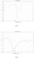
- FIG. 4 is a schematic diagram of S parameter at a low frequency band of the antenna according to an embodiment of the present disclosure.
- FIG. 5 is a schematic diagram of S parameter at a high frequency band of the antenna according to an embodiment of the present disclosure.
- the antenna provided by the above-mentioned embodiment can operate at 0.94 GHz-1.11 GHz (low frequency band) and 5.18 GHz-6.0 GHz (high frequency band). Thus, coverage can be achieved for both the 900 MHz (17.8%) and 5.8 GHz frequency bands.
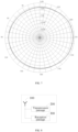
- FIG. 6 and FIG. 7 are directional views of the antenna in the low frequency band and the high frequency band according to the embodiment of the present disclosure; As shown in FIGs. 6 and 7 , the antenna disposed by the embodiment of the present disclosure has good directivity, good omni-directivity and no defect in a specific direction in both the low frequency band and the high frequency band.
- An embodiment of the present disclosure still further provides a wireless signal processing device based on the antenna disposed in the above-mentioned embodiments.
- the present embodiment is not limited to a specific implementation of the wireless signal processing device, and may be any type or kind of electronic device for wireless signal transceiving, such as a remote controller, an intelligent terminal, a wearable device, or a signal transceiver of a mobile carrier.
- FIG. 8 is a schematic structural diagram of a wireless signal processing device according to an embodiment of the present disclosure.
- the wireless signal processing device includes: an antenna 100, a transmission passage 200, and a reception passage 300.
- the antenna 100 is connected with the reception passage 200 or the transmission passage 300 through a feed line to realize signal transmission with each other.
- the antenna 100 may be embodied as described in one or more of the above-mentioned embodiments, depending on the particular implementation of the wireless signal processing device.
- the antenna 100 may be an omni-directional antenna covering two frequency bands.
- the transmission passage 200 is a functional module for loading information content to be transmitted into a carrier signal to form a wireless signal. It can be embodied in any type of electronic system, formed by a combination of one or more electronic elements, that can generate wireless signals, such as a radio frequency chip.
- the reception passage 300 is an electronic system, such as a particular model of decoding chip, for parsing the wireless signal received by the antenna to obtain the information content contained in the wireless signal. It has an opposite information flow direction to the transmission passage 200, and is a functional module for completing information acquisition.
- one of the transmission passage 200 and the reception passage 300 may be obviated.
- the reception passage 300 may be omitted, and only the transmission passage 200 may be disposed.
- FIG. 9 is a schematic structural diagram of an antenna used in an unmanned aerial vehicle according to an embodiment of the present disclosure.
- unmanned aerial vehicle technology With the development of unmanned aerial vehicle technology, it is always desirable to reduce the fuselage volume of unmanned aerial vehicles as much as possible so that unmanned aerial vehicles can be adapted to perform missions in more scenes.
- higher demands are placed on the size and structure of the antenna, which is expected to be possible in a limited volume and as simple a structure as possible.
- the unmanned aerial vehicle may include: a fuselage 400, motors (510, 520), and an antenna.
- the fuselage 400 may be made of any suitable material and have a structure and size suitable for use (such as the fixed wing unmanned aerial vehicle shown in FIG. 9 ).
- a variety of different functional components may be disposed on the fuselage 400, such as landing gear 410, a propeller 420, a camera 430, etc.
- a person skilled in the art would also have been able to add or omit one or more functional components as required by the actual situation. For example, a corresponding pan-tilt 440 can be added to the camera 430.
- the motors (510, 520) are mounted to the fuselage 400 for providing flight power to the unmanned aerial vehicle.
- the motor may be provided with one or more motors disposed at corresponding positions of the fuselage 400 (e.g. a fuselage motor 510, a wingtip motor 520) for performing different functions (e.g. driving rotation of the propeller 420, controlling posture of the fuselage, etc.).
- the antenna may be mounted and housed within the landing gear 410 (e.g. within a rear landing gear shown in FIG. 9 and designated by reference numeral 410) as part of a wireless signal transceiving device for receiving remote control operation instructions from a remote control or for feeding back relevant data information (e.g. captured images, operational status parameters of the unmanned aerial vehicle itself) to a remote control or other intelligent terminal.
- relevant data information e.g. captured images, operational status parameters of the unmanned aerial vehicle itself
Landscapes
- Physics & Mathematics (AREA)
- Engineering & Computer Science (AREA)
- Aviation & Aerospace Engineering (AREA)
- Remote Sensing (AREA)
- Electromagnetism (AREA)
- Astronomy & Astrophysics (AREA)
- General Physics & Mathematics (AREA)
- Details Of Aerials (AREA)
- Aerials With Secondary Devices (AREA)
Abstract
Description
- The present disclosure claims the priority of the Chinese patent application filed on
March 26, 2021 before the CNIPA, China National Intellectual Property Administration with the application number of 2021103264209 - Embodiments of the present disclosure relate to the field of antenna structure technology, and more particularly, to an antenna, a wireless signal processing device, and an unmanned aerial vehicle.
- The antenna is a key component for transmitting and receiving electromagnetic wave wireless signals. Its performance has a significant impact on the unmanned aerial vehicle and other devices that need long-range wireless data transmission. With the continuous development of electronic information technology, the demand of wireless transmission for the number of coverage frequency bands and bandwidth is increasing. This presents a major challenge to the structural design of the antenna.
- To meet higher and higher bandwidth requirements, complex structural designs are often required to achieve larger bandwidths. However, the complicated structure of the antenna makes the volume of the antenna unable to be controlled effectively, making it difficult to realize miniaturization, and making it difficult to apply to small products sensitive to the size and structure, such as unmanned aerial vehicles and remote controllers.
- The embodiments of the present disclosure aim to provide an antenna, a wireless signal processing device and an unmanned aerial vehicle, which can solve the problems of complicated structure and difficult miniaturization of existing large-bandwidth antennas.
- In order to solve the above-mentioned technical problem, embodiments of the present disclosure provide the following technical solutions: an antenna. The antenna includes:
- a substrate having a first surface and a second surface opposite the first surface;
- a first radiator and a second radiator disposed on the first surface, the first radiator and the second radiator facing opposite each other, the first radiator being located at one end near a head of the substrate, and the second radiator being located at one end near a root of the substrate;
- a third radiator disposed on the second surface, the third radiator being mirror symmetric with a portion of a structure of the first radiator and conducting with the second radiator, so that the first radiator, the second radiator and the third radiator form a coupled resonance point; and
- a feed line connected with the first radiator, the second radiator and the third radiator.
- Optionally, the antenna further includes a fourth radiator and a fifth radiator disposed on the second surface; and
the fourth radiator and the fifth radiator are symmetrically disposed and have opposite orientations, and the fourth radiator is oriented towards one end of the head of the substrate. - Optionally, the feed line comprises a first feed line and a second feed line;
- the first feed line runs on the first surface of the substrate and is connected with the first radiator, the second radiator and the third radiator; and
- the second feed line runs on the second surface of the substrate and is connected with the fourth radiator and the fifth radiator.
- Optionally, the first feed line and the second feed line are coaxial lines;
- the first radiator is connected with an inner conductor of the first feed line, and the second radiator and the third radiator form a passage and are connected with an outer conductor of the first feed line; and
- the fourth radiator is connected with an inner conductor of the second feed line, and the fifth radiator is connected with an outer conductor of the second feed line.
- Optionally, the first radiator and the second radiator are disposed symmetrically along an axial direction of the substrate.
- Optionally, a difference between an effective length of the first radiator and an effective length of the second radiator is greater than zero and less than a predetermined length threshold.
- Optionally, the first radiator further includes:
- a first radiator body having a predetermined length extending in a radial direction of the substrate;
- a pair of first vibrating arms respectively formed at two ends of the first radiator body and extending in an axial direction of the substrate;
- a first microstrip line disposed on an axis of symmetry of the first radiator, a length of the first microstrip line being greater than that of the vibrating arms and the first microstrip line being in communication with the radiator main body; and
- a pair of second microstrip lines disposed between the first microstrip line and the first vibrating arms, a length of the second microstrip lines being greater than that of the first microstrip line and the second microstrip lines being in communication with the radiator main body.
- Optionally, the third radiator is mirror symmetric with the first radiator body and the pair of the second microstrip lines.
- Optionally, the second radiator further includes:
- a second radiator body having a predetermined length extending in a radial direction of the substrate;
- a pair of second vibrating arms, the second vibrating arms being formed extending in an axial direction of the substrate at a position near an end of the second radiator body; and
- a pair of third microstrip lines disposed between the pair of second vibrating arms.
- Optionally, the third microstrip lines extend to one end of the root of the substrate; and a width of the third microstrip lines is greater than that of the second vibrating arms.
- Optionally, the fourth radiator comprises: a fourth radiator body and a pair of fourth vibrating arms formed by two ends of the fourth radiator extending in an axial direction of the substrate.
- Optionally, the first radiator, the second radiator and the third radiator constitute a first radiation portion, and the fourth radiator and the fifth radiator constitute a second radiation portion; and
the first radiation portion corresponds to a first frequency band; the second radiation portion corresponds to a second frequency band and has a dimension length of between 1/8 and 3/4 of a resonance wavelength of the second frequency band; the first frequency band has a higher frequency than the second frequency band. - Optionally, the first frequency band is a 900 MHz frequency band and the second frequency band is a 5.8 GHz frequency band.
- Optionally, the antenna further comprises: a pad having a predetermined size, and
the pad is disposed between the feed line and the substrate to maintain the feed line at a distance from the substrate. - Optionally, the pad includes: a foam layer, a plastic rack or a wood rack.
- Optionally, a fixing means for fixing the feed line and the pad on the substrate includes: bundling fixation or pasting fixation.
- In order to solve the above-mentioned technical problem, the embodiment of the present disclosure further provides the following technical solution: a wireless signal processing device. The wireless signal processing device includes: the antenna as described above for transmitting or receiving a wireless signal; a reception passage for parsing a wireless signal received by the antenna so as to acquire information content contained in the wireless signal; a transmission passage for loading the information content into a radio frequency carrier signal, forming a wireless signal and transmitting the wireless signal via the antenna.
- In order to solve the above-mentioned technical problem, the embodiment of the present disclosure further provides the following technical solution: an unmanned aerial vehicle. The unmanned aerial vehicle includes: a fuselage having a landing gear thereon; a motor mounted at a connection of the fuselage and the landing gear for providing flight power for the unmanned aerial vehicle; and the antenna as described above, mounted within the landing gear.
- The antenna of the embodiment of the present disclosure adopts a reasonable wiring and structural design, and uses the first radiator, the second radiator and the third radiator respectively located on two sides of the substrate to constitute a coupled resonance point, so that a larger bandwidth can be realized on a substrate with a smaller volume, and the defect that it is difficult for an antenna with a large bandwidth to be miniaturized is overcome.
- One or more embodiments are illustrated by way of example, and not by way of limitation on the embodiments, via figures in the corresponding accompanying drawings, in which elements having the same reference numeral designations represent similar elements, and in which the figures in the accompanying drawings are not to scale unless otherwise specified.
-
FIG. 1 is a schematic structural diagram of an antenna according to an embodiment of the present disclosure; -
FIG. 2 is a schematic structural diagram of a first radiator and a second radiator according to an embodiment of the present disclosure; -
FIG. 3 is a side view of the antenna according to an embodiment of the present disclosure; -
FIG. 4 is a schematic diagram of a low frequency S parameter of the antenna according to an embodiment of the present disclosure; -
FIG. 5 is a schematic diagram of a high frequency S parameter of the antenna according to an embodiment of the present disclosure; -
FIG. 6 is a directional view of the antenna in a low frequency band according to an embodiment of the present disclosure; -
FIG. 7 is a directional view of the antenna in a high frequency band according to an embodiment of the present disclosure; -
FIG. 8 is a schematic diagram of a wireless signal processing device according to an embodiment of the present disclosure; and -
FIG. 9 is a schematic diagram of the antenna according to an embodiment of the present disclosure in an application scenario of an unmanned aerial vehicle. - In order to facilitate an understanding of the present disclosure, a more detailed description of the disclosure is provided below in connection with the accompanying drawings and specific embodiments. It will be understood that when an element is referred to as being "fixed" to another element, it can be directly on the other element or intervening elements may be present. When an element is referred to as being "connected" to another element, it can be directly connected to the other element or intervening elements may be present. In the description, the orientation or positional relationship indicated by the terms "upper", "lower", "inner", "outer", "bottom", etc. is based on the orientation or positional relationship shown in the drawings, merely to facilitate the description of the present disclosure and simplify the description, and does not indicate or imply that the devices or elements referred to must have a particular orientation, be constructed and operated in a particular orientation, and thus should not be construed as limiting the present disclosure. Furthermore, the terms "first", "second", "third", and the like are used for descriptive purposes only and are not to be construed as indicating or implying relative importance.
- Unless otherwise defined, all technical and scientific terms used herein have the same meaning as commonly understood by one of ordinary skill in the art to which the present disclosure belongs. The terminology used in the description of the present disclosure herein is for the purpose of describing particular embodiments only and is not intended to be limiting of the disclosure. As used herein, the term "and/or" includes any and all combinations of one or more of the associated listed items.
- Furthermore, the features of the various embodiments of the present disclosure described below can be combined as long as they do not conflict with each other.
-
FIG. 1 is a schematic structural diagram of an antenna according to an embodiment of the present disclosure. In the present embodiment, the front surface of the antenna is referred to as a "first surface A" while the back surface thereof is referred to as a "second surface B" for convenience of presentation. The "first" and "second" are only used to distinguish a front side from a back side of thesubstrate 10 and are not used to define a surface. - As shown in
FIG. 1 , the antenna mainly includes asubstrate 10 as a base of an antenna structure, radiators (211, 212, 213, 221, 222) having a specific structural shape disposed on the first surface A and the second surface B of the substrate, and feed lines (31, 32) connected with the radiators. - Among other things, the
substrate 10 may be a non-conductive structure fabricated from any type of material (e.g. plastic, foam) and having a particular shape (e.g. trapezoidal). It has a relatively flat shape, forming a flat first surface and a second surface. - The radiator is a conductor (e.g. copper foil) having a specific shape and length disposed on a surface of the substrate. It can be fixed on the surface of the substrate by any suitable form (such as patch type), and exposed to the outside, so as to realize the reception or transmission of wireless signals in a specific frequency band through the principle of electromagnetic induction.
- One or more of the radiators may form a resonant cell for receiving or transmitting wireless signals in a specific frequency band. In the present embodiment, such a resonance unit may be referred to as a "radiation portion". In a multi-frequency antenna, it is generally possible to have a plurality of radiation portions, each for covering or corresponding to a different frequency band.
- In some embodiments, the
substrate 10 may be disposed with afirst radiator 211, asecond radiator 212 and athird radiator 213 constituting afirst radiation portion 21 corresponding to a first frequency band. - Therein, the
first radiator 211 and thesecond radiator 212 are disposed on the first surface A, and are facing opposite each other. In particular, as shown inFIG. 1 , thefirst radiator 211 is oriented in a direction opposite to a direction of extension of the feed line and thesecond radiator 212 is oriented in the same direction as the direction of extension of the feed line. - In addition, the
second radiator 212 is located closer to a root of the substrate (i.e. an end through which the feed line leaves the substrate) than thefirst radiator 211. In other words, thefirst radiator 211 is located closer to a head of the substrate. In this embodiment, for simplicity of presentation, an end near the direction of extension of the feed line is referred to as the "root of the substrate", and an end away from the direction of extension of the feed line is referred to as a "head of the substrate". - The
third radiator 213 is a radiator disposed on the back side (i.e. the second surface B) of the substrate. Thethird radiator 213 has a same structural form as a part of thefirst radiator 211. It has a "mirror symmetry" relationship with the structure of thefirst radiator 211. - The mirror-image symmetry may also be referred to as mirror symmetry, meaning that the radiator structures at two opposite surfaces of the substrate is symmetrical with respect to the plane of the substrate. In other words, the
third radiator 213 may be regarded as a radiator structure formed after a part of the radiator structure in thefirst radiator 211 is horizontally inverted to the second surface B. - In addition, the
third radiator 213 is also in communication or conduction with thesecond radiator 212. In other words, thethird radiator 213 and thesecond radiator 212 belong to the same passage. In particular, thethird radiator 213 on the back side of thesubstrate 10 can pass through the substrate to establish a connection with thesecond radiator 212 on the front side of the substrate 10 (as a communicating wire) in any suitable manner. - In this embodiment, the space of the substrate is fully utilized, and the first radiator, the second radiator and the third radiator can constitute a coupled resonance point by the above-mentioned routing arrangement of the reasonable antenna structure, so that the bandwidth of the first radiation portion is greatly improved, and the antenna can achieve structural miniaturization while meeting the use requirements of a larger bandwidth.
- Thus, a person skilled in the art would have been able to adjust one or more of an effective length, radiator shape or other similar radiator parameters of the
first radiator 211, thesecond radiator 212 and thethird radiator 213 as required by the actual situation (such as the frequency band corresponding to the first radiation portion). All the adjustments, changes or substitutions made to the present application in order to realize that thefirst radiator 211, thesecond radiator 212 and thethird radiator 213 are coupled with each other and constitute a coupled resonance point fall within the scope of protection of the present application. - As will be appreciated by those skilled in the art, the length of the radiator (which may also be referred to as dimensional length or effective length) is an important dimensional parameter in the antenna and is closely related to the frequency band at which the wireless signal is received or transmitted.
- In a preferred embodiment, the
first radiator 211 may have an effective length slightly greater thansecond radiator 212. The expression "slightly greater than" means that the difference between the two is less than a certain threshold or within a smaller range of values. In other words, the difference between the effective length of thefirst radiator 211 and the effective length of thesecond radiator 212 is in the range of zero to a preset length threshold. - The predetermined length threshold indicates a degree of difference between the effective lengths of the
first radiator 211 and thesecond radiator 212. The length threshold is an empirical value that can be selectively set by a person skilled in the art as required by the actual situation to achieve the effect that the effective length of thefirst radiator 211 is slightly greater than that of thesecond radiator 212. -
FIG. 2 is a schematic structural diagram of thefirst radiator 211 and thesecond radiator 212 according to an embodiment of the present disclosure. In carrying out the present application, it has surprisingly been found that good antenna performance can be achieved with a relatively small volume using the radiator structure shown inFIG. 2 . - The
first radiator 211 and thesecond radiator 212 are symmetrically disposed along the axial direction of thesubstrate 40. In other words, the structures of thefirst radiator 211 and thesecond radiator 212 on both sides of the axis of the substrate are symmetrical. - As shown in
FIG. 2 , thefirst radiator 211 may include: a first radiator main body 211a, a first vibrating arm 211b, afirst microstrip line 211c and asecond microstrip line 211d. - Here, the first radiator body 211a is a conductor structure of the microstrip line or the like having a predetermined length extending along a radial direction of the substrate, while the radial direction refers to a direction perpendicular to the axial direction of the substrate. The predetermined length is an empirical value and can be set by the person skilled in the art as required by the actual situation.
- The first vibrating arms 211b are provided in a pair, respectively located at two ends of the first radiator body 211a, and are symmetrical along the axis of the substrate. A direction of extension of the first vibrating arms 211b is in the axial direction and extends a certain length toward the head of the substrate.
- The
first microstrip line 211c is similar to the first vibrating arms 211b, and likewise extends a certain length from the first radiator body in the axial direction. The difference is that the position thereof is located on a symmetry axis (namely, the axis of the substrate) of the first radiator, and overlaps the symmetry axis. In other words, thefirst microstrip line 211c is located between the first vibrating arms 211b on both sides and has a length greater than that of the first vibrating arms 211b, so as to be combined with the first vibrating arms 211b and the radiator body 211a into a radiator shape similar to a "" shape.
- Further, the
second microstrip lines 211d are also provided in a pair at positions on both sides of the axis of the substrate between thefirst microstrip line 211c and the first vibrating arms 211b. Thesecond microstrip lines 211d also communicate with the first radiator body 211a and have a large length than thefirst microstrip line 211c, thus forming a complete first radiator structure. - Specifically, the
second microstrip lines 211d may have an inclination extending from the radiator body 211a to a length greater than that of thefirst microstrip line 211c. - In some embodiments, as shown in
FIG. 1 , the third radiator disposed on the second surface B may have an radiator structure similar to a "π" pattern, in a mirror symmetric relationship with the radiator structure composed of the first radiator body 211a of the first radiator disposed on the first surface A and a pair ofthird microstrip lines 211c. - With continued reference to
FIG. 2 , thesecond radiator 212 may be generally divided into: asecond radiator body 212a, a second vibrating arm 212b, athird microstrip line 212c, etc. - The
second radiator body 212a has a predetermined length extending in the radial direction of the substrate similar to the first radiator body 211a. - The second vibrating arms 212b are also provided in a pair, and are formed by extending a certain length in the axial direction of the substrate at positions near two ends of the second radiator body, respectively.
- The
third microstrip line 212c is disposed between the pair of second vibrating arms 212b and maintains symmetry along the axis of the substrate. Specifically, thethird microstrip line 212c and the second vibrating arms 212b may both have a certain inclination so as to form a radiator structure like a "π" pattern with thesecond radiator body 212a on one side of the axis of the substrate. Thus, thesecond radiator 212 as a whole has an radiator structure similar to a double "π" pattern. - In a preferred embodiment, the
third microstrip line 212c extending to the end of the root of the substrate can be used, and a width w1 of thethird microstrip line 212c is made greater than a width w2 of the second vibrating arm 212b to improve coverage of the signals with a low band frequency by the antenna. - In other embodiments, with reference to
FIG. 1 again, the antenna may, in addition to the first radiation portion, include a second radiation portion 22 comprising afourth radiator 221 and a fifth radiator 222. - A frequency band corresponding to the second radiation portion 22 is different from the frequency band corresponding to the
first radiation portion 21, and the second radiation portion 22 corresponds to a higher second frequency band. Thus, it is possible to cover a high frequency band by the second radiation portion and a low frequency band by the first radiation portion, thereby obtaining a dual frequency antenna. - Of course, the first frequency band corresponding to the
first radiation portion 21 and the second frequency band corresponding to the second radiation portion 22 can be set as required by the actual situation, and are not limited to specific frequency bands. The terms "first" and "second" are used only to distinguish between the frequency bands corresponding to or covered by the two radiation portions, meaning the relative level of frequencies between the two. - Here, the
fourth radiator 221 and the fifth radiator 222 may adopt a dipole structure which is symmetrically disposed and has opposite orientations. Thefourth radiator 221 faces one end of the head of the substrate, and the fifth radiator 222 faces one end of the root of the substrate, and thefourth radiator 221 and the fifth radiator 222 are symmetrically disposed along a straight line where the radial direction of the substrate lies. - Specifically, the
fourth radiator 221 may be composed of a fourth radiator main body 221a and a pair of fourth vibrating arms 221b formed at both ends of the fourth radiator so as to extend in the axial direction of the substrate to form a U-shaped radiator structure. The fifth radiator 222 adopts a symmetrical structure with respect to thefourth radiator 221, and a description thereof will not be repeated here for simplicity of presentation. - The feed lines (31, 32) are lines connecting the "radiation portions" with other signal processing systems to form a signal transmission passage. In particular, any suitable type of wire having sufficient shielding and signal transmission properties (like an axis) may be used. In some embodiments, corresponding to the two radiation portions, two feed lines may also be provided as a first feed line 31 and a
second feed line 32 for transmitting a low-frequency band signal and a high-frequency band signal, respectively, running on the first surface A and the second surface B of thesubstrate 10. - As shown in
FIG. 1 , the feed lines (31, 32) generally need to extend a certain length in the direction of the root of the substrate, starting from the position where they are connected with the radiation portions, until they leave thesubstrate 10. In other words, thefeed line 30 will pass or travel on the surface of the substrate. "Travel" refers to the situation where the feed lines (31, 32) pass or pass at a distance from the surface of thesubstrate 10. - When the feed lines (31, 32) transmit signals, they may affect or interfere with the resonant signals of the radiation portions of the surface of the substrate which they pass. In a preferred embodiment, the interference caused by the transmission of signals by the feed lines (31, 32) can be reduced as much as possible by providing the
pad 40. - With continued reference to
FIG. 1 , thepad 40 is a filling structure disposed between the feed lines (31, 32) and the surface of the substrate. It has a predetermined size, the pad being below the feed line so that thefeed line 30 remains at a sufficient distance from the surface of the substrate. - In this embodiment, "dimension" refers to a combination of parameters (e.g. thickness, width, or length) associated with a profile of the pad to characterize the external profile of the filling structure, and the particular parameters involved may be determined based on the actual selected profile of the
pad 40 or the desired distance of the feed lines (31, 32) from the surface of the substrate. - The above-mentioned predetermined dimension is an empirical value, which can be determined by a person skilled in the art as required by the actual situation, and only needs to be able to keep the feed lines (31, 32) at a sufficient distance from the substrate.
- The distance between the feed lines (31, 32) and the substrate may be characterized or measured by one or more parameters. For example, a vertical distance between the feed lines (31, 32) and the surface of the substrate may be used.
- This vertical distance is an empirical value and only needs to be sufficient for use. A person skilled in the art would have been able to predetermine a minimum standard or a suitable standard to be satisfied by the vertical distance between the feed lines (31, 32) and the surface of the substrate as required by the actual situation (such as performance indicators and experimental results), and then choose to use a pad with a corresponding size.
- In particular, the
pad 40 may be made of any suitable type of non-conductive material, including but not limited to foam, plastic, and wood, as a structure to bed the feed line. In view of the different materials of construction specifically used for thepad 40, corresponding structures may also be used. For example, when foam is used, thepad 40 may be a foam layer having a certain thickness (e.g. foam with a thickness of 0.5 mm), and when wood or plastic is used, a wood frame or a plastic frame having a shape structure adapted to the feed lines (31, 32) may be selected as thepad 40. - In other embodiments, in order to avoid relative movement between the feed lines (31, 32) and the
substrate 10 and thepad 40 during daily use of the antenna, the feed lines (31, 32) may be fixed to thepad 40 by any suitable type of fixing means (e.g. pasting fixation or bundling fixation), keeping thesubstrate 10, thepad 40 and thefeed line 30 integrally fixed. - Specifically, as shown in
FIG. 3 , when the bundling fixation is used, the feed lines (31, 32) and thepad 40 can be bundled and fixed on thesubstrate 10 by means of a rope form of ahemp rope 60 or the like at intervals of distance, through a hollowinggroove 70 or other likewise holes disposed on thesubstrate 10. - In particular, a suitable quantity of
hemp ropes 60 may be disposed according to distance or length that thefeed line 30 travels on thesubstrate 10. Of course, other non-conductive bundling materials (e.g. plastic strapping) that do not interfere with the reception or transmission of signals by the antenna may also be used. - However, in the case of using the pasting fixation, the feed lines (31, 32), the
pad 40 and thesubstrate 10 may be paste-fixed by an adhesive having a paste force such as an appropriate type of glue or adhesive tape. Of course, the above-mentioned pasting fixation and bundling fixation may also be used in combination and not necessarily independently. For example, thepad 40 may be pasted and fixed to thesubstrate 10, and the feed lines (31, 32) may be bundled and fixed to thepad 40. - In the antenna structure disposed in the embodiments of the present disclosure, by arranging a filling structure with a reasonable size between the feed lines (31, 32) and the surface of the substrate to heighten the feed lines (31, 32) so as to ensure that the feed lines (31, 32) traveling on the substrate keep a certain distance from the surface of the substrate, the effect of reducing the influence or interference of the feed lines (31, 32) on a resonant wave (such as a high-frequency signal or a low-frequency signal corresponding to the above-mentioned radiation portions) during signal transmission can be achieved, which is beneficial for improving the overall performance of the antenna.
- It should be noted that the antenna shown in
FIG. 1 is merely for illustrative purposes, and one skilled in the art may add, adjust, replace, or subtract one or more functional components as the actual situation requires, and the solution is not limited to that shown inFIG. 1 . The technical features involved in the embodiment of the antenna shown inFIG. 1 can be combined with each other as long as they do not constitute a conflict, and can be applied independently in different embodiments as long as they do not constitute a dependency. - Embodiments of the present disclosure provide a specific example of a dual frequency antenna that can operate in both the 900 MHz and 5.8 GHz frequency bands.
- As shown in
FIG. 1 , the dual-frequency antenna includes: asubstrate 10, afirst radiator 211, asecond radiator 212, athird radiator 213, afourth radiator 221, a fifth radiator 222, a sixth radiator 233, a first feed line 31, asecond feed line 32 and apad 40. - The
first radiator 211 adopts an radiator shape similar to a "" shape as a whole, and a pair of inclined microstrip lines are newly added on the radiator shape of the " " shape. The
second radiator 212 takes the shape of an radiator formed by superposition of two "π" characters, and the effective length of the first radiator is slightly greater than the effective length of the second radiator. - The
third radiator 213 is disposed on the back side and has an radiator shape like a "π" form (which is mirror symmetry with a portion of the first radiator 211). Thethird radiator 213 communicates with thesecond radiator 212 and belongs to the same passage. - The first feed line 31 uses a coaxial line, the
first radiator 211 is connected with an inner conductor of the coaxial line 31, and the passage where thesecond radiator 212 and thethird radiator 213 are located is connected with an outer conductor of the coaxial line 31. The first feed line 31 traveling on the front side of thesubstrate 10 is fixed on thesubstrate 10 by means of a hemp rope bundling. A foam layer with a thickness of 0.5 mm is disposed between the first feed line 31 and thesubstrate 10 to ensure that a sufficient distance is maintained between the first feed line 31 and the first surface A. - The
first radiator 211, thesecond radiator 212 and thethird radiator 213 constitute a coupled resonance point, and as a first radiation portion, correspond to a low frequency band (900 MHz), providing a large low frequency bandwidth. - The
fourth radiator 221 and the fifth radiator 222 are also disposed on the back side of the substrate, and constitute a second radiation portion to cover the high frequency band (5.8 GHz). Thefourth radiator 221 and the fifth radiator 222 each adopt a "U"-shaped radiator structure, and a total length of the sizes of the two radiators is controlled within a range of 1/8 to 3/4 of a high-frequency resonance wavelength. - The
second feed line 32 travels on the back side of thesubstrate 10 and is likewise coaxial. Thefourth radiator 221 is connected with an inner conductor of thecoaxial line 32 and the fifth radiator 222 is connected with an outer conductor of thecoaxial line 32. Similarly to the first feed line 31, thesecond feed line 32 is also fixed to thesubstrate 10 in a bundling fixation by means of a plurality of sets of hemp ropes passing through thesubstrate 10, and a foam layer with a thickness of 0.5 mm is likewise disposed between the second surface B of thesubstrate 10 and thesecond feed line 32 to ensure a distance between thesecond feed line 32 and the second surface B. -
FIG. 4 is a schematic diagram of S parameter at a low frequency band of the antenna according to an embodiment of the present disclosure.FIG. 5 is a schematic diagram of S parameter at a high frequency band of the antenna according to an embodiment of the present disclosure. - As shown in
FIGs. 4 and 5 , the antenna provided by the above-mentioned embodiment can operate at 0.94 GHz-1.11 GHz (low frequency band) and 5.18 GHz-6.0 GHz (high frequency band). Thus, coverage can be achieved for both the 900 MHz (17.8%) and 5.8 GHz frequency bands. -
FIG. 6 andFIG. 7 are directional views of the antenna in the low frequency band and the high frequency band according to the embodiment of the present disclosure; As shown inFIGs. 6 and7 , the antenna disposed by the embodiment of the present disclosure has good directivity, good omni-directivity and no defect in a specific direction in both the low frequency band and the high frequency band. - An embodiment of the present disclosure still further provides a wireless signal processing device based on the antenna disposed in the above-mentioned embodiments. The present embodiment is not limited to a specific implementation of the wireless signal processing device, and may be any type or kind of electronic device for wireless signal transceiving, such as a remote controller, an intelligent terminal, a wearable device, or a signal transceiver of a mobile carrier.
-
FIG. 8 is a schematic structural diagram of a wireless signal processing device according to an embodiment of the present disclosure. As shown inFIG. 8 , the wireless signal processing device includes: anantenna 100, atransmission passage 200, and areception passage 300. Theantenna 100 is connected with thereception passage 200 or thetransmission passage 300 through a feed line to realize signal transmission with each other. - The
antenna 100 may be embodied as described in one or more of the above-mentioned embodiments, depending on the particular implementation of the wireless signal processing device. For example, theantenna 100 may be an omni-directional antenna covering two frequency bands. - The
transmission passage 200 is a functional module for loading information content to be transmitted into a carrier signal to form a wireless signal. It can be embodied in any type of electronic system, formed by a combination of one or more electronic elements, that can generate wireless signals, such as a radio frequency chip. - The
reception passage 300 is an electronic system, such as a particular model of decoding chip, for parsing the wireless signal received by the antenna to obtain the information content contained in the wireless signal. It has an opposite information flow direction to thetransmission passage 200, and is a functional module for completing information acquisition. - In some embodiments, based on different specific implementations of the wireless signal processing device, one of the
transmission passage 200 and thereception passage 300 may be obviated. For example, when the wireless signal processing device is a remote control, thereception passage 300 may be omitted, and only thetransmission passage 200 may be disposed. - Embodiments of the present disclosure still further provide application scenarios for the antenna disposed by the above-mentioned embodiments.
FIG. 9 is a schematic structural diagram of an antenna used in an unmanned aerial vehicle according to an embodiment of the present disclosure. - With the development of unmanned aerial vehicle technology, it is always desirable to reduce the fuselage volume of unmanned aerial vehicles as much as possible so that unmanned aerial vehicles can be adapted to perform missions in more scenes. However, in the case of a reduced volume of the fuselage of the unmanned aerial vehicle, higher demands are placed on the size and structure of the antenna, which is expected to be possible in a limited volume and as simple a structure as possible.
- Thus, with the antenna disposed by embodiments of the present disclosure, the requirements of an unmanned aerial vehicle having a smaller fuselage with respect to the volume and structure of the antenna can be well met. As shown in
FIG. 9 , the unmanned aerial vehicle may include: afuselage 400, motors (510, 520), and an antenna. - As the main structure of the unmanned aerial vehicle, the
fuselage 400 may be made of any suitable material and have a structure and size suitable for use (such as the fixed wing unmanned aerial vehicle shown inFIG. 9 ). A variety of different functional components may be disposed on thefuselage 400, such aslanding gear 410, apropeller 420, acamera 430, etc. Of course, a person skilled in the art would also have been able to add or omit one or more functional components as required by the actual situation. For example, a correspondingpan-tilt 440 can be added to thecamera 430. - The motors (510, 520) are mounted to the
fuselage 400 for providing flight power to the unmanned aerial vehicle. The motor may be provided with one or more motors disposed at corresponding positions of the fuselage 400 (e.g. afuselage motor 510, a wingtip motor 520) for performing different functions (e.g. driving rotation of thepropeller 420, controlling posture of the fuselage, etc.). - The antenna may be mounted and housed within the landing gear 410 (e.g. within a rear landing gear shown in
FIG. 9 and designated by reference numeral 410) as part of a wireless signal transceiving device for receiving remote control operation instructions from a remote control or for feeding back relevant data information (e.g. captured images, operational status parameters of the unmanned aerial vehicle itself) to a remote control or other intelligent terminal. - Of course, based on the application scenarios of the unmanned aerial vehicle disposed by the embodiments, a person skilled in the art could also apply the antenna disposed by the above-mentioned embodiments to other similar unmanned mobile carriers, not limited to the unmanned aerial vehicle shown in
FIG. 9 . - Finally, it should be noted that: the above embodiments are merely illustrative of the technical solutions of the present invention, rather than limiting it; combinations of features in the above embodiments or in different embodiments are also possible within the spirit of the invention, the steps can be implemented in any order, and there are many other variations of the different aspects of the invention described above, which are not provided in detail for the sake of brevity; although the present invention has been described in detail with reference to the foregoing embodiments, those skilled in the art will appreciate that: the technical solutions disclosed in the above-mentioned embodiments can still be amended, or some of the technical features thereof can be replaced by equivalents; such modifications and substitutions do not depart from the spirit and scope of the embodiments of the present invention.
Claims (18)
- An antenna, characterized by comprising:a substrate having a first surface and a second surface opposite the first surface;a first radiator and a second radiator disposed on the first surface, the first radiator and the second radiator facing opposite each other, the first radiator being located at one end near a head of the substrate, and the second radiator being located at one end near a root of the substrate;a third radiator disposed on the second surface, the third radiator being mirror symmetric with a portion of a structure of the first radiator and conducting with the second radiator, so that the first radiator, the second radiator and the third radiator form a coupled resonance point; anda feed line connected with the first radiator, the second radiator and the third radiator.
- The antenna according to claim 1, characterized by further comprising: a fourth radiator and a fifth radiator disposed on the second surface;
the fourth radiator and the fifth radiator being symmetrically disposed and having opposite orientations, and the fourth radiator being oriented towards one end of the head of the substrate. - The antenna according to claim 2, characterized in that the feed line comprises a first feed line and a second feed line;the first feed line runs on the first surface of the substrate and is connected with the first radiator, the second radiator and the third radiator; andthe second feed line runs on the second surface of the substrate and is connected with the fourth radiator and the fifth radiator.
- The antenna according to claim 3, characterized in that the first feed line and the second feed line are coaxial lines;the first radiator is connected with an inner conductor of the first feed line, and the second radiator and the third radiator form a passage and are connected with an outer conductor of the first feed line; andthe fourth radiator is connected with an inner conductor of the second feed line, and the fifth radiator is connected with an outer conductor of the second feed line.
- The antenna according to claim 1, characterized in that the first radiator and the second radiator are disposed symmetrically along an axial direction of the substrate.
- The antenna according to claim 1, characterized in that a difference between an effective length of the first radiator and an effective length of the second radiator is greater than zero and less than a predetermined length threshold.
- The antenna according to claim 4 or 5 or 6, characterized in that the first radiator comprises:a first radiator body having a predetermined length extending in a radial direction of the substrate;a pair of first vibrating arms respectively formed at two ends of the first radiator body and extending in an axial direction of the substrate;a first microstrip line disposed on an axis of symmetry of the first radiator, a length of the first microstrip line being greater than that of the vibrating arms and the first microstrip line being in communication with the radiator main body; anda pair of second microstrip lines disposed between the first microstrip line and the first vibrating arms, a length of the second microstrip lines being greater than that of the first microstrip line and the second microstrip lines being in communication with the radiator main body.
- The antenna according to claim 7, characterized in that the third radiator is mirror symmetric with the first radiator body and the pair of the second microstrip lines.
- The antenna according to claim 4 or 5 or 6, characterized in that the second radiator comprises:a second radiator body having a predetermined length extending in a radial direction of the substrate;a pair of second vibrating arms, the second vibrating arms being formed extending in an axial direction of the substrate at a position near an end of the second radiator body; anda pair of third microstrip lines disposed between the pair of second vibrating arms.
- The antenna according to claim 9, characterized in that the third microstrip lines extend to one end of the root of the substrate; and a width of the third microstrip lines is greater than that of the second vibrating arms.
- The antenna according to any of claims 2-5, characterized in that the fourth radiator comprises: a fourth radiator body and a pair of fourth vibrating arms formed by two ends of the fourth radiator extending in an axial direction of the substrate.
- The antenna according to any one of claims 2-5, characterized in that the first radiator, the second radiator and the third radiator constitute a first radiation portion, and the fourth radiator and the fifth radiator constitute a second radiation portion; and
the first radiation portion corresponds to a first frequency band; the second radiation portion corresponds to a second frequency band and has a dimension length of between 1/8 and 3/4 of a resonance wavelength of the second frequency band; the first frequency band has a higher frequency than the second frequency band. - The antenna according to claim 12, characterized in that the first frequency band is a 900 MHz frequency band and the second frequency band is a 5.8 GHz frequency band.
- The antenna according to any of claims 1-6, characterized in that the antenna further comprises: a pad having a predetermined size, and
the pad is disposed between the feed line and the substrate to maintain the feed line at a distance from the substrate. - The antenna according to claim 14, characterized in that the pad comprises: a foam layer, a plastic rack or a wood rack.
- The antenna according to claim 14, characterized in that a fixing means for fixing the feed line and the pad on the substrate comprises: bundling fixation or pasting fixation.
- A wireless signal processing device, characterized by comprising:the antenna according to any one of claims 1-16 for transmitting or receiving a wireless signal; anda transmission passage for loading information content into a radio frequency carrier signal, forming a wireless signal and transmitting the wireless signal via the antenna.
- An unmanned aerial vehicle, characterized by comprising:a fuselage having a landing gear thereon;a motor mounted on the fuselage for providing flight power for the unmanned aerial vehicle; andthe antenna according to any one of claims 1-16 mounted within the landing gear.
Applications Claiming Priority (2)
| Application Number | Priority Date | Filing Date | Title |
|---|---|---|---|
| CN202110326420.9A CN112886215B (en) | 2021-03-26 | 2021-03-26 | Antennas, wireless signal processing equipment and drones |
| PCT/CN2022/079360 WO2022199363A1 (en) | 2021-03-26 | 2022-03-04 | Antenna, wireless signal processing device and unmanned aerial vehicle |
Publications (2)
| Publication Number | Publication Date |
|---|---|
| EP4318801A1 true EP4318801A1 (en) | 2024-02-07 |
| EP4318801A4 EP4318801A4 (en) | 2024-09-18 |
Family
ID=76042562
Family Applications (1)
| Application Number | Title | Priority Date | Filing Date |
|---|---|---|---|
| EP22774025.5A Pending EP4318801A4 (en) | 2021-03-26 | 2022-03-04 | ANTENNA, WIRELESS SIGNAL PROCESSING DEVICE AND UNMANNED AERIAL VEHICLE |
Country Status (4)
| Country | Link |
|---|---|
| US (1) | US12476368B2 (en) |
| EP (1) | EP4318801A4 (en) |
| CN (1) | CN112886215B (en) |
| WO (1) | WO2022199363A1 (en) |
Families Citing this family (2)
| Publication number | Priority date | Publication date | Assignee | Title |
|---|---|---|---|---|
| CN112886215B (en) * | 2021-03-26 | 2025-06-06 | 深圳市道通智能航空技术股份有限公司 | Antennas, wireless signal processing equipment and drones |
| CN114784483B (en) * | 2022-03-18 | 2025-10-24 | 深圳市道通智能航空技术股份有限公司 | Antenna and drone |
Family Cites Families (15)
| Publication number | Priority date | Publication date | Assignee | Title |
|---|---|---|---|---|
| TW560107B (en) * | 2002-09-24 | 2003-11-01 | Gemtek Technology Co Ltd | Antenna structure of multi-frequency printed circuit |
| US7064729B2 (en) * | 2003-10-01 | 2006-06-20 | Arc Wireless Solutions, Inc. | Omni-dualband antenna and system |
| US7369094B2 (en) * | 2006-09-26 | 2008-05-06 | Smartant Telecom Co., Ltd. | Dual-frequency high-gain antenna |
| US7755559B2 (en) * | 2008-12-09 | 2010-07-13 | Mobile Mark, Inc. | Dual-band omnidirectional antenna |
| TWI427858B (en) * | 2009-04-10 | 2014-02-21 | Advanced Connectek Inc | Digital TV antenna |
| CN203850420U (en) * | 2014-03-03 | 2014-09-24 | 深圳市安拓浦科技有限公司 | Double face thin sheet antenna |
| CN105990651A (en) * | 2015-03-05 | 2016-10-05 | 中兴通讯股份有限公司 | Dual polarization antenna |
| CN111883922B (en) * | 2017-05-22 | 2023-05-30 | 深圳市大疆创新科技有限公司 | Antenna and unmanned aerial vehicle's signal processing equipment |
| US11211697B2 (en) * | 2017-10-12 | 2021-12-28 | TE Connectivity Services Gmbh | Antenna apparatus |
| CN120016137A (en) * | 2019-10-22 | 2025-05-16 | 深圳市道通智能航空技术股份有限公司 | Dual-band antennas and unmanned aerial vehicles |
| CN211126036U (en) * | 2019-10-22 | 2020-07-28 | 深圳市道通智能航空技术有限公司 | Dual-frequency antenna and unmanned aerial vehicle |
| CN110931965B (en) * | 2019-10-25 | 2022-05-17 | 深圳市道通智能航空技术股份有限公司 | Dual-band antenna and aircraft |
| CN112531352A (en) * | 2020-12-08 | 2021-03-19 | 南京长峰航天电子科技有限公司 | Broadband multi-polarization plane reflective array antenna |
| CN112886215B (en) * | 2021-03-26 | 2025-06-06 | 深圳市道通智能航空技术股份有限公司 | Antennas, wireless signal processing equipment and drones |
| CN215220988U (en) * | 2021-03-26 | 2021-12-17 | 深圳市道通智能航空技术股份有限公司 | Antenna, wireless signal processing equipment and unmanned aerial vehicle |
-
2021
- 2021-03-26 CN CN202110326420.9A patent/CN112886215B/en active Active
-
2022
- 2022-03-04 EP EP22774025.5A patent/EP4318801A4/en active Pending
- 2022-03-04 WO PCT/CN2022/079360 patent/WO2022199363A1/en not_active Ceased
-
2023
- 2023-09-26 US US18/373,109 patent/US12476368B2/en active Active
Also Published As
| Publication number | Publication date |
|---|---|
| CN112886215B (en) | 2025-06-06 |
| WO2022199363A1 (en) | 2022-09-29 |
| EP4318801A4 (en) | 2024-09-18 |
| US12476368B2 (en) | 2025-11-18 |
| US20240030605A1 (en) | 2024-01-25 |
| CN112886215A (en) | 2021-06-01 |
Similar Documents
| Publication | Publication Date | Title |
|---|---|---|
| AU2018423290B2 (en) | Antenna system and terminal device | |
| US12476368B2 (en) | Antenna, wireless signal processing device, and unmanned aerial vehicle | |
| US9685695B2 (en) | Antenna system and antenna unit | |
| EP2429031A1 (en) | Antenna designing method and data card mono-plate of wireless terminal | |
| WO2019228309A1 (en) | Antenna, remote controller of unmanned aerial vehicle, and unmanned aerial vehicle | |
| WO2022199362A1 (en) | Antenna, wireless signal processing device and unmanned aerial vehicle | |
| WO2021078260A1 (en) | Dual-band antenna and aerial vehicle | |
| US20240079765A1 (en) | Antenna, wireless signal processing device, and unmanned aerial vehicle | |
| US20250269989A1 (en) | Modified Antenna Ground Plane For Space-Constrained Designs | |
| CN205376749U (en) | Unmanned aerial vehicle high -gain multielement antenna | |
| CN108767436B (en) | Antenna and unmanned aerial vehicle | |
| US20210114710A1 (en) | Unmanned aerial vehicle and antenna thereof | |
| CN216928924U (en) | Antenna, wireless signal processing equipment and unmanned aerial vehicle | |
| CN215220988U (en) | Antenna, wireless signal processing equipment and unmanned aerial vehicle | |
| WO2022199361A1 (en) | Antenna, antenna debugging method, external antenna structure, and unmanned aerial vehicle | |
| CN215220987U (en) | Antenna, wireless signal processing equipment and unmanned aerial vehicle | |
| CN113067143B (en) | An antenna and a remote control | |
| CN215220986U (en) | Antenna, wireless signal processing equipment and unmanned aerial vehicle | |
| KR20240042087A (en) | Broadband antenna placed in vehicle | |
| CN108134194A (en) | A kind of miniaturization WLAN dual-band PIFA antennas | |
| CN214898855U (en) | Antenna, external antenna structure and unmanned aerial vehicle | |
| CN211126059U (en) | Dual-band antenna and aircraft | |
| CN208209007U (en) | Slot antenna suitable for vehicle-mounted equipment | |
| CN218415008U (en) | Antenna, wireless signal processing equipment and unmanned aerial vehicle | |
| CN111029719B (en) | Antenna and aircraft |
Legal Events
| Date | Code | Title | Description |
|---|---|---|---|
| STAA | Information on the status of an ep patent application or granted ep patent |
Free format text: STATUS: THE INTERNATIONAL PUBLICATION HAS BEEN MADE |
|
| PUAI | Public reference made under article 153(3) epc to a published international application that has entered the european phase |
Free format text: ORIGINAL CODE: 0009012 |
|
| STAA | Information on the status of an ep patent application or granted ep patent |
Free format text: STATUS: REQUEST FOR EXAMINATION WAS MADE |
|
| 17P | Request for examination filed |
Effective date: 20231026 |
|
| AK | Designated contracting states |
Kind code of ref document: A1 Designated state(s): AL AT BE BG CH CY CZ DE DK EE ES FI FR GB GR HR HU IE IS IT LI LT LU LV MC MK MT NL NO PL PT RO RS SE SI SK SM TR |
|
| DAV | Request for validation of the european patent (deleted) | ||
| DAX | Request for extension of the european patent (deleted) | ||
| REG | Reference to a national code |
Ref country code: DE Ref legal event code: R079 Free format text: PREVIOUS MAIN CLASS: H01Q0001280000 Ipc: H01Q0009280000 |
|
| A4 | Supplementary search report drawn up and despatched |
Effective date: 20240821 |
|
| RIC1 | Information provided on ipc code assigned before grant |
Ipc: H01Q 21/28 20060101ALN20240814BHEP Ipc: H01Q 21/10 20060101ALN20240814BHEP Ipc: H01Q 5/48 20150101ALN20240814BHEP Ipc: H01Q 5/371 20150101ALN20240814BHEP Ipc: H01Q 1/28 20060101ALN20240814BHEP Ipc: H01Q 5/378 20150101ALI20240814BHEP Ipc: H01Q 9/28 20060101AFI20240814BHEP |