EP4318760A1 - Verfahren zur herstellung einer batteriewanne für ein kraftfahrzeug - Google Patents
Verfahren zur herstellung einer batteriewanne für ein kraftfahrzeug Download PDFInfo
- Publication number
- EP4318760A1 EP4318760A1 EP22188578.3A EP22188578A EP4318760A1 EP 4318760 A1 EP4318760 A1 EP 4318760A1 EP 22188578 A EP22188578 A EP 22188578A EP 4318760 A1 EP4318760 A1 EP 4318760A1
- Authority
- EP
- European Patent Office
- Prior art keywords
- max
- circuit board
- preferred
- battery tray
- battery
- Prior art date
- Legal status (The legal status is an assumption and is not a legal conclusion. Google has not performed a legal analysis and makes no representation as to the accuracy of the status listed.)
- Pending
Links
- 238000000034 method Methods 0.000 title claims abstract description 26
- 229910000851 Alloy steel Inorganic materials 0.000 claims abstract description 6
- 238000009966 trimming Methods 0.000 claims abstract description 6
- 238000004080 punching Methods 0.000 claims abstract description 4
- 238000010438 heat treatment Methods 0.000 claims abstract description 3
- 238000004519 manufacturing process Methods 0.000 claims abstract description 3
- 239000000463 material Substances 0.000 claims description 9
- 238000000576 coating method Methods 0.000 claims description 6
- 239000011248 coating agent Substances 0.000 claims description 5
- XEEYBQQBJWHFJM-UHFFFAOYSA-N Iron Chemical compound [Fe] XEEYBQQBJWHFJM-UHFFFAOYSA-N 0.000 claims description 4
- 239000011324 bead Substances 0.000 claims description 3
- 229910045601 alloy Inorganic materials 0.000 claims description 2
- 239000000956 alloy Substances 0.000 claims description 2
- 229910052804 chromium Inorganic materials 0.000 claims description 2
- 239000012535 impurity Substances 0.000 claims description 2
- 229910052742 iron Inorganic materials 0.000 claims description 2
- 238000002844 melting Methods 0.000 claims description 2
- 230000008018 melting Effects 0.000 claims description 2
- 229910052750 molybdenum Inorganic materials 0.000 claims description 2
- 239000000843 powder Substances 0.000 claims 1
- 238000004146 energy storage Methods 0.000 description 6
- 229910000734 martensite Inorganic materials 0.000 description 5
- BASFCYQUMIYNBI-UHFFFAOYSA-N platinum Chemical compound [Pt] BASFCYQUMIYNBI-UHFFFAOYSA-N 0.000 description 4
- HCHKCACWOHOZIP-UHFFFAOYSA-N Zinc Chemical compound [Zn] HCHKCACWOHOZIP-UHFFFAOYSA-N 0.000 description 2
- CSDREXVUYHZDNP-UHFFFAOYSA-N alumanylidynesilicon Chemical compound [Al].[Si] CSDREXVUYHZDNP-UHFFFAOYSA-N 0.000 description 2
- 230000000977 initiatory effect Effects 0.000 description 2
- 238000003856 thermoforming Methods 0.000 description 2
- 229910052725 zinc Inorganic materials 0.000 description 2
- 239000011701 zinc Substances 0.000 description 2
- 229910000859 α-Fe Inorganic materials 0.000 description 2
- 229910000831 Steel Inorganic materials 0.000 description 1
- 229910001563 bainite Inorganic materials 0.000 description 1
- 230000015572 biosynthetic process Effects 0.000 description 1
- 239000000969 carrier Substances 0.000 description 1
- 210000004027 cell Anatomy 0.000 description 1
- 238000004140 cleaning Methods 0.000 description 1
- 238000002485 combustion reaction Methods 0.000 description 1
- 230000008878 coupling Effects 0.000 description 1
- 238000010168 coupling process Methods 0.000 description 1
- 238000005859 coupling reaction Methods 0.000 description 1
- 230000001419 dependent effect Effects 0.000 description 1
- 230000000694 effects Effects 0.000 description 1
- 238000005516 engineering process Methods 0.000 description 1
- 230000007613 environmental effect Effects 0.000 description 1
- 230000007774 longterm Effects 0.000 description 1
- 239000011159 matrix material Substances 0.000 description 1
- 239000002184 metal Substances 0.000 description 1
- 229910052751 metal Inorganic materials 0.000 description 1
- 239000007769 metal material Substances 0.000 description 1
- 238000010422 painting Methods 0.000 description 1
- 229910001562 pearlite Inorganic materials 0.000 description 1
- 230000000750 progressive effect Effects 0.000 description 1
- 239000010959 steel Substances 0.000 description 1
- 238000003860 storage Methods 0.000 description 1
- 210000000352 storage cell Anatomy 0.000 description 1
- 230000007704 transition Effects 0.000 description 1
Images


Classifications
-
- H—ELECTRICITY
- H01—ELECTRIC ELEMENTS
- H01M—PROCESSES OR MEANS, e.g. BATTERIES, FOR THE DIRECT CONVERSION OF CHEMICAL ENERGY INTO ELECTRICAL ENERGY
- H01M50/00—Constructional details or processes of manufacture of the non-active parts of electrochemical cells other than fuel cells, e.g. hybrid cells
- H01M50/20—Mountings; Secondary casings or frames; Racks, modules or packs; Suspension devices; Shock absorbers; Transport or carrying devices; Holders
- H01M50/218—Mountings; Secondary casings or frames; Racks, modules or packs; Suspension devices; Shock absorbers; Transport or carrying devices; Holders characterised by the material
- H01M50/22—Mountings; Secondary casings or frames; Racks, modules or packs; Suspension devices; Shock absorbers; Transport or carrying devices; Holders characterised by the material of the casings or racks
- H01M50/222—Inorganic material
- H01M50/224—Metals
-
- B—PERFORMING OPERATIONS; TRANSPORTING
- B23—MACHINE TOOLS; METAL-WORKING NOT OTHERWISE PROVIDED FOR
- B23P—METAL-WORKING NOT OTHERWISE PROVIDED FOR; COMBINED OPERATIONS; UNIVERSAL MACHINE TOOLS
- B23P15/00—Making specific metal objects by operations not covered by a single other subclass or a group in this subclass
-
- B—PERFORMING OPERATIONS; TRANSPORTING
- B32—LAYERED PRODUCTS
- B32B—LAYERED PRODUCTS, i.e. PRODUCTS BUILT-UP OF STRATA OF FLAT OR NON-FLAT, e.g. CELLULAR OR HONEYCOMB, FORM
- B32B15/00—Layered products comprising a layer of metal
- B32B15/01—Layered products comprising a layer of metal all layers being exclusively metallic
- B32B15/012—Layered products comprising a layer of metal all layers being exclusively metallic one layer being formed of an iron alloy or steel, another layer being formed of aluminium or an aluminium alloy
-
- B—PERFORMING OPERATIONS; TRANSPORTING
- B32—LAYERED PRODUCTS
- B32B—LAYERED PRODUCTS, i.e. PRODUCTS BUILT-UP OF STRATA OF FLAT OR NON-FLAT, e.g. CELLULAR OR HONEYCOMB, FORM
- B32B15/00—Layered products comprising a layer of metal
- B32B15/01—Layered products comprising a layer of metal all layers being exclusively metallic
- B32B15/013—Layered products comprising a layer of metal all layers being exclusively metallic one layer being formed of an iron alloy or steel, another layer being formed of a metal other than iron or aluminium
-
- B—PERFORMING OPERATIONS; TRANSPORTING
- B60—VEHICLES IN GENERAL
- B60K—ARRANGEMENT OR MOUNTING OF PROPULSION UNITS OR OF TRANSMISSIONS IN VEHICLES; ARRANGEMENT OR MOUNTING OF PLURAL DIVERSE PRIME-MOVERS IN VEHICLES; AUXILIARY DRIVES FOR VEHICLES; INSTRUMENTATION OR DASHBOARDS FOR VEHICLES; ARRANGEMENTS IN CONNECTION WITH COOLING, AIR INTAKE, GAS EXHAUST OR FUEL SUPPLY OF PROPULSION UNITS IN VEHICLES
- B60K1/00—Arrangement or mounting of electrical propulsion units
- B60K1/04—Arrangement or mounting of electrical propulsion units of the electric storage means for propulsion
-
- C—CHEMISTRY; METALLURGY
- C21—METALLURGY OF IRON
- C21D—MODIFYING THE PHYSICAL STRUCTURE OF FERROUS METALS; GENERAL DEVICES FOR HEAT TREATMENT OF FERROUS OR NON-FERROUS METALS OR ALLOYS; MAKING METAL MALLEABLE, e.g. BY DECARBURISATION OR TEMPERING
- C21D1/00—General methods or devices for heat treatment, e.g. annealing, hardening, quenching or tempering
- C21D1/18—Hardening; Quenching with or without subsequent tempering
-
- C—CHEMISTRY; METALLURGY
- C21—METALLURGY OF IRON
- C21D—MODIFYING THE PHYSICAL STRUCTURE OF FERROUS METALS; GENERAL DEVICES FOR HEAT TREATMENT OF FERROUS OR NON-FERROUS METALS OR ALLOYS; MAKING METAL MALLEABLE, e.g. BY DECARBURISATION OR TEMPERING
- C21D1/00—General methods or devices for heat treatment, e.g. annealing, hardening, quenching or tempering
- C21D1/62—Quenching devices
- C21D1/673—Quenching devices for die quenching
-
- C—CHEMISTRY; METALLURGY
- C21—METALLURGY OF IRON
- C21D—MODIFYING THE PHYSICAL STRUCTURE OF FERROUS METALS; GENERAL DEVICES FOR HEAT TREATMENT OF FERROUS OR NON-FERROUS METALS OR ALLOYS; MAKING METAL MALLEABLE, e.g. BY DECARBURISATION OR TEMPERING
- C21D7/00—Modifying the physical properties of iron or steel by deformation
- C21D7/13—Modifying the physical properties of iron or steel by deformation by hot working
-
- C—CHEMISTRY; METALLURGY
- C21—METALLURGY OF IRON
- C21D—MODIFYING THE PHYSICAL STRUCTURE OF FERROUS METALS; GENERAL DEVICES FOR HEAT TREATMENT OF FERROUS OR NON-FERROUS METALS OR ALLOYS; MAKING METAL MALLEABLE, e.g. BY DECARBURISATION OR TEMPERING
- C21D9/00—Heat treatment, e.g. annealing, hardening, quenching or tempering, adapted for particular articles; Furnaces therefor
- C21D9/46—Heat treatment, e.g. annealing, hardening, quenching or tempering, adapted for particular articles; Furnaces therefor for sheet metals
- C21D9/48—Heat treatment, e.g. annealing, hardening, quenching or tempering, adapted for particular articles; Furnaces therefor for sheet metals deep-drawing sheets
-
- C—CHEMISTRY; METALLURGY
- C22—METALLURGY; FERROUS OR NON-FERROUS ALLOYS; TREATMENT OF ALLOYS OR NON-FERROUS METALS
- C22C—ALLOYS
- C22C38/00—Ferrous alloys, e.g. steel alloys
- C22C38/02—Ferrous alloys, e.g. steel alloys containing silicon
-
- C—CHEMISTRY; METALLURGY
- C22—METALLURGY; FERROUS OR NON-FERROUS ALLOYS; TREATMENT OF ALLOYS OR NON-FERROUS METALS
- C22C—ALLOYS
- C22C38/00—Ferrous alloys, e.g. steel alloys
- C22C38/04—Ferrous alloys, e.g. steel alloys containing manganese
-
- C—CHEMISTRY; METALLURGY
- C22—METALLURGY; FERROUS OR NON-FERROUS ALLOYS; TREATMENT OF ALLOYS OR NON-FERROUS METALS
- C22C—ALLOYS
- C22C38/00—Ferrous alloys, e.g. steel alloys
- C22C38/06—Ferrous alloys, e.g. steel alloys containing aluminium
-
- C—CHEMISTRY; METALLURGY
- C22—METALLURGY; FERROUS OR NON-FERROUS ALLOYS; TREATMENT OF ALLOYS OR NON-FERROUS METALS
- C22C—ALLOYS
- C22C38/00—Ferrous alloys, e.g. steel alloys
- C22C38/12—Ferrous alloys, e.g. steel alloys containing tungsten, tantalum, molybdenum, vanadium, or niobium
-
- C—CHEMISTRY; METALLURGY
- C22—METALLURGY; FERROUS OR NON-FERROUS ALLOYS; TREATMENT OF ALLOYS OR NON-FERROUS METALS
- C22C—ALLOYS
- C22C38/00—Ferrous alloys, e.g. steel alloys
- C22C38/14—Ferrous alloys, e.g. steel alloys containing titanium or zirconium
-
- C—CHEMISTRY; METALLURGY
- C22—METALLURGY; FERROUS OR NON-FERROUS ALLOYS; TREATMENT OF ALLOYS OR NON-FERROUS METALS
- C22C—ALLOYS
- C22C38/00—Ferrous alloys, e.g. steel alloys
- C22C38/18—Ferrous alloys, e.g. steel alloys containing chromium
- C22C38/32—Ferrous alloys, e.g. steel alloys containing chromium with boron
-
- C—CHEMISTRY; METALLURGY
- C22—METALLURGY; FERROUS OR NON-FERROUS ALLOYS; TREATMENT OF ALLOYS OR NON-FERROUS METALS
- C22C—ALLOYS
- C22C38/00—Ferrous alloys, e.g. steel alloys
- C22C38/18—Ferrous alloys, e.g. steel alloys containing chromium
- C22C38/38—Ferrous alloys, e.g. steel alloys containing chromium with more than 1.5% by weight of manganese
-
- H—ELECTRICITY
- H01—ELECTRIC ELEMENTS
- H01M—PROCESSES OR MEANS, e.g. BATTERIES, FOR THE DIRECT CONVERSION OF CHEMICAL ENERGY INTO ELECTRICAL ENERGY
- H01M50/00—Constructional details or processes of manufacture of the non-active parts of electrochemical cells other than fuel cells, e.g. hybrid cells
- H01M50/20—Mountings; Secondary casings or frames; Racks, modules or packs; Suspension devices; Shock absorbers; Transport or carrying devices; Holders
- H01M50/249—Mountings; Secondary casings or frames; Racks, modules or packs; Suspension devices; Shock absorbers; Transport or carrying devices; Holders specially adapted for aircraft or vehicles, e.g. cars or trains
-
- B—PERFORMING OPERATIONS; TRANSPORTING
- B60—VEHICLES IN GENERAL
- B60Y—INDEXING SCHEME RELATING TO ASPECTS CROSS-CUTTING VEHICLE TECHNOLOGY
- B60Y2304/00—Optimising design; Manufacturing; Testing
-
- C—CHEMISTRY; METALLURGY
- C21—METALLURGY OF IRON
- C21D—MODIFYING THE PHYSICAL STRUCTURE OF FERROUS METALS; GENERAL DEVICES FOR HEAT TREATMENT OF FERROUS OR NON-FERROUS METALS OR ALLOYS; MAKING METAL MALLEABLE, e.g. BY DECARBURISATION OR TEMPERING
- C21D2211/00—Microstructure comprising significant phases
- C21D2211/005—Ferrite
-
- C—CHEMISTRY; METALLURGY
- C21—METALLURGY OF IRON
- C21D—MODIFYING THE PHYSICAL STRUCTURE OF FERROUS METALS; GENERAL DEVICES FOR HEAT TREATMENT OF FERROUS OR NON-FERROUS METALS OR ALLOYS; MAKING METAL MALLEABLE, e.g. BY DECARBURISATION OR TEMPERING
- C21D2211/00—Microstructure comprising significant phases
- C21D2211/008—Martensite
-
- C—CHEMISTRY; METALLURGY
- C21—METALLURGY OF IRON
- C21D—MODIFYING THE PHYSICAL STRUCTURE OF FERROUS METALS; GENERAL DEVICES FOR HEAT TREATMENT OF FERROUS OR NON-FERROUS METALS OR ALLOYS; MAKING METAL MALLEABLE, e.g. BY DECARBURISATION OR TEMPERING
- C21D2261/00—Machining or cutting being involved
Definitions
- the present invention relates to a method for producing a battery tray for a battery carrier of a motor vehicle with the features in claim 1.
- the energy storage itself is made of rechargeable energy storage cells, also called accumulators or batteries or traction batteries. So that these can be carried in the motor vehicle, but are also protected from the effects of the weather and, if in doubt, also protected in the event of a vehicle crash, the energy storage devices are housed in so-called battery carriers or battery trays. Battery trays are built cases, usually having a tray and a lid that closes the tray. Both plastic materials and metallic materials can be used as materials.
- a battery tray serves either to hold at least one battery or a battery module by inserting the battery(s) into the battery tray.
- the battery tray can also be designed as a hood, which is placed over the battery(s) and thus closes a battery holder.
- the object of the present invention is to provide a battery tray that is simple to produce compared to the prior art, has a high longevity and has a certain inherent rigidity in crash behavior.
- the method according to the invention is characterized in that a one-piece circuit board with the same material is provided and the battery tray is therefore produced in a hot forming and press hardening process by means of deep drawing.
- Hot forming and press hardening technology is used so that a circuit board on a hardenable steel alloy used is brought to a temperature greater than AC1, in particular greater than AC3, to which the entire circuit board is heated completely and homogeneously.
- the AC1 temperature is a temperature of approximately 700° to 750° C.
- the AC3 temperature would be a temperature of approximately 900 to 950° C.
- a battery tray can therefore be used as a tray for inserting batteries .
- a battery tray can also be used as a lid, with the lid then being placed over a battery holder.
- the hot forming and press hardening process sets a martensite content in the material structure of at least 5% after the press hardening process has been completed.
- the martensite content does not exceed 50% and is in particular less than 35%.
- the material structure has a ferrite matrix with martensite inclusions at the grain boundaries.
- the ferrite content is particularly preferably 50% to 80%, the martensite content is preferably 10% to 35%.
- the remaining structural components are tempered bainite/martensite and/or pearlite.
- a significant advantage is that at the same time as the hot forming, the edge trimming or perforation of the formed battery tray is also carried out. In particular, this is carried out as hot trimming or hot punching at a temperature between 400° and 700° C.
- a tensile strength Rm is set in the finished battery tray, between 350 and 850 MPa, in particular 600 to 750, preferably 650 to 720 MPa.
- the yield strength A50 is preferably from 6% to 20%, in particular 10% to 18% and preferably 12% to 16%.
- this makes it possible to produce a battery tray that has sufficient strength to meet the rigidity requirements, especially if it is installed in a self-supporting body or also takes on a supporting structure.
- the batteries can therefore remain safely stored in the interior of the battery tray.
- the battery tray Even in the event of an unintentional motor vehicle crash, the battery tray has a high level of inherent rigidity and at the same time good elasticity, so that it deforms without tearing. The body is thus given sufficient rigidity by the battery tray. At the same time, it prevents the battery tray from tearing unnecessarily in the event of a vehicle crash, so that no battery contents are released into the environment and thus environmental protection is ensured.
- a pre-coated circuit board is used, with an aluminum-silicon-based coating or, preferably, a zinc-based coating.
- an aluminum-silicon-coated board is heated to greater than AC3 within at least 120 s, alternatively, a zinc-coated board is heated to greater than AC1 within at least 60 s.
- the coatings it is possible here for the coatings to be alloyed with the base material, which is preferably designed according to the steel positions mentioned above.
- a sheet metal thickness of the board between 0.5 mm and 2.5 mm, preferably between 1 mm and 2 mm.
- the board itself has a dimension of greater than 1300 mm by 1800 mm, in particular greater than 1500 mm by 2300 mm.
- a radius is set between the base and side wall or between the side wall and flange based on a wall thickness ratio of 5 to 10. This means the radius is 5 to 10 times larger than the wall thickness. This ratio also resulted in a positive forming process with simultaneous fatigue strength of the later battery tray.
- crack initiation is not promoted by excessive forming gradients during the deep-drawing process of hot forming, but rather avoided.
- stiffening beads can be formed in one piece and using the same material in the bottom of the battery tray during the hot forming process.
- FIG. 1 shows the method according to the invention.
- a circuit board 2 is provided in a thermoforming line 1.
- the circuit board 2 is heated in an oven device 3 and then inserted as a heated circuit board 4 into a forming device 5, in particular into a hot forming press hardening tool.
- the battery tray 6 produced in this way can then be removed.
- the battery tray 6 itself is in Figure 2 shown in perspective view. This has a base 7, side walls 8 extending all around from the base 7 and a flange 9 projecting outwards from side walls 8.
- the flange 9 serves according to Figure 3 shown for coupling with a cover 10.
- Battery storage in the form of rechargeable batteries 11 or individual battery cells are then arranged inside the battery tray 6 arranged in this way.
- stiffening beads 12 can be formed in one piece and made of the same material, which extend here in the transverse direction Y of the motor vehicle. In the event of a side crash, greater rigidity is therefore achieved.
- longitudinal beams 13 may be arranged inside the battery carrier. The longitudinal beams 13 then served as a receptacle, for example as screwing points for the batteries.
- an angle ⁇ is formed between the bottom 7 and the side wall 8, between 80° and 90°, in particular at approximately 85°. This does not ensure optimal removal from the hot forming tool after the press hardening process has been completed.
- the result is a ratio of wall thickness 14 to radius 15, from 5 to 10. This means that radius 15 is approx. 5 times to 10 times as large as the wall thickness 14 of the battery tray 6.
- An analogous angle as well as radius 15 then results in the transition from side wall 8 to flange 9. Holes within the flange 9 or an edge trimming of the flange 9, which is also in the hot forming press hardening tool according to, are not shown in more detail Figure 1 can be carried out. However, it can also be carried out in a progressive tool.
Landscapes
- Chemical & Material Sciences (AREA)
- Engineering & Computer Science (AREA)
- Mechanical Engineering (AREA)
- Materials Engineering (AREA)
- Organic Chemistry (AREA)
- Metallurgy (AREA)
- Crystallography & Structural Chemistry (AREA)
- Thermal Sciences (AREA)
- Physics & Mathematics (AREA)
- General Chemical & Material Sciences (AREA)
- Electrochemistry (AREA)
- Chemical Kinetics & Catalysis (AREA)
- Aviation & Aerospace Engineering (AREA)
- Inorganic Chemistry (AREA)
- Combustion & Propulsion (AREA)
- Transportation (AREA)
- Sealing Battery Cases Or Jackets (AREA)
- Battery Mounting, Suspending (AREA)
Abstract
Die vorliegende Erfindung betrifft ein Verfahren zur Herstellung einer Batteriewanne (6) für ein Kraftfahrzeug und ist gekennzeichnet durch folgende Verfahrensschritte:• Bereitstellen einer Platine (2) aus einer härtbaren Stahlblechlegierung, optional ist die Platine (2) vorbeschichtet,• Vollständiges Erwärmen auf eine Temperatur größer AC1, insbesondere größer AC3,• Warmumformen und Presshärten der Platine (2) , zu einer Batteriewanne (6) mit einem flächigen Boden, davon umlaufend abstehenden Seitenwänden (8) und von den Seitenwänden (8) umlaufend abstehendem nach außen orientiertem Flansch (9),• Randbeschnitt und/oder Lochen der Platine und/oder der umgeformten Batteriewanne (6) bei einer Temperatur zwischen 400° und 700° C,• Einstellen einer Zugfestigkeit zwischen 350 und 850MPa.
Description
- Die vorliegende Erfindung betrifft ein Verfahren zur Herstellung einer Batteriewanne für einen Batterieträger eines Kraftfahrzeuges mit den Merkmalen im Anspruch 1.
- Aus dem Stand der Technik ist es bekannt, Kraftfahrzeuge im Straßenverkehr zu betreiben. Diese Kraftfahrzeuge werden entweder von Verbrennungskraftmaschinen angetrieben oder aber von Elektromotoren. Folglich werden elektrisch angetriebene Kraftfahrzeuge auch Elektrofahrzeuge oder Elektrokraftfahrzeuge genannt. Bei elektrisch angetriebenen Kraftfahrzeugen wird ein Energiespeicher benötigt, um Reichweiten von mehreren hundert Kilometern zu realisieren. Ein solcher Energiespeicher ist platz-, gewichts-, jedoch auch flächenintensiv. Zumeist wird ein Energiespeicher am oder im Unterboden eines Kraftfahrzeuges untergebracht.
- Der Energiespeicher selbst ist aus wiederaufladbaren Energiespeicherzellen, auch Akkus bzw. Batterien oder Traktionsbatterien genannt, ausgebildet. Damit diese sowohl im Kraftfahrzeug mitgeführt werden können, jedoch auch vor Witterungseinflüssen geschützt sind und im Zweifel auch bei einem Fahrzeugcrash geschützt sind, werden die Energiespeicher in sog. Batterieträgern bzw. battery trays untergebracht. Battery trays sind dabei gebaute Hüllen, zumeist aufweisend eine Wanne und einen die Wanne verschließenden Deckel. Als Werkstoffe kommen sowohl Kunststoffwerkstoffe als auch metallische Werkstoffe in Frage.
- Eine Batteriewanne dient dabei entweder zur Aufnahme von mindestens einer Batterie bzw. eines Batteriemoduls durch Einlegen der Batterie(n) in die Batteriewanne. Alternativ kann die Batteriewanne auch als Haube ausgebildet sein, welche über Batterie(n) gestülpt wird und einen Batteriehalter somit verschließt.
- Aufgabe der vorliegenden Erfindung ist es, eine Batteriewanne bereit zu stellen, die gegenüber dem Stand der Technik einfach zu produzieren ist, eine hohe Langlebigkeit aufweist und im Crashverhalten eine gewisse Eigensteifigkeit mit sich bringt.
- Die zuvor genannte Aufgabe wird erfindungsgemäß mit einen Verfahren mit den Merkmalen im Anspruch 1 gelöst.
- Vorteilhafte Ausgestaltungsvarianten der vorliegenden Erfindung sind Gegenstand der abhängigen Ansprüche.
- Das erfindungsgemäße Verfahren dient zur Herstellung einer Batteriewanne für einen Batterieträger eines Kraftfahrzeuges und ist gekennzeichnet durch folgende Verfahrensschritte:
- Bereitstellen einer Platine aus einer härtbaren Stahlblechlegierung, optional ist die Platine vorbeschichtet,
- Vollständiges Erwärmen auf eine Temperatur größer AC1, insbesondere größer AC3,
- Warmumformen und Presshärten der Platine, zu einer Batteriewanne mit einem flächigen Boden, davon umlaufend abstehenden Seitenwänden und von den Seitenwänden umlaufend abstehendem nach außen orientiertem Flansch,
- Randbeschnitt und/oder Lochen der Platine und/oder der umgeformten Batteriewanne bei einer Temperatur zwischen 400° und 700° C,
- Einstellen einer Zugfestigkeit zwischen 350 und 850MPa.
- Das erfindungsgemäße Verfahren zeichnet sich dabei dadurch aus, dass eine einstückige und werkstoffeinheitliche Platine bereitgestellt wird und in einem Warmumform- und Presshärtevorgang mithin mittels Tiefziehen die Batteriewanne hergestellt wird. Dabei wird die Warmumform- und Presshärtetechnologie angewendet, so dass eine Platine an einer verwendeten härtbaren Stahllegierung auf eine Temperatur größer AC1, insbesondere größer AC3 gebracht wird, auf welche die gesamte Platine vollständig und homogen erwärmt wird. Die AC1-Temperatur ist dabei eine Temperatur von ca. 700° bis 750° C. Die AC3-Temperatur wäre eine Temperatur von ca. 900 bis 950° C. Eine Batteriewanne kann somit als Wanne zur Aufnahme in Form von Einlegen von Batterien verwendet werden. Eine Batteriewanne kann jedoch auch als Deckel verwendet werden, wobei der Deckel dann über einen Batteriehalter gestülpt wird.
- Weiterhin wird durch den Warmumform- und Presshärteprozess ein Martensitanteil in dem Werkstoffgefüge nach Abschluss des Presshärteprozesses von mindestens 5 % eingestellt. Der Martensitanteil überschreitet jedoch nicht 50 % und ist insbesondere kleiner 35 %. Insbesondere weist das Werkstoffgefüge eine Ferritmatrix mit Martensiteinschlüssen an den Korngrenzen auf. Der Ferritanteil beträgt besonders bevorzugt 50 % bis 80 %, der Martensitanteil bevozugt 10 % bis 35 %. Die restlichen Gefügebestandteile sind getempertes Bainit/Martensit und/oder Perlit.
- Ein wesentlicher Vorteil liegt darin, dass gleichzeitig mit dem Warmumformen auch ein Randbeschnitt bzw. ein Lochen der umgeformten Batteriewanne durchgeführt wird. Insbesondere wird dies als Warmbeschnitt bzw. Warmlochen bei einer Temperatur zwischen 400° und 700° C durchgeführt.
- Insgesamt wird somit bei der fertigen Batteriewanne eine Zugfestigkeit Rm eingestellt, zwischen 350 und 850 MPa, insbesondere 600 bis 750, bevorzugt 650 bis 720 MPa. Die Dehngrenze A50 beträgt bevorzugt von 6 % bis 20 %, insbesondere 10 % bis 18 % und vorzugsweise 12 % bis 16 %.
- Erfindungsgemäß hat sich herausgestellt, dass hierdurch eine Batteriewanne hergestellt werden kann, die eine hinreichende Festigkeit aufweist, um die Steifigkeitsanforderungen zu erfüllen, insbesondere, wenn diese in eine selbsttragende Karosserie eingebaut ist bzw. auch eine tragende Struktur mit übernimmt. Gleichzeitig ist eine hinreichende Duktilität gegeben, um im dauerhaften Betrieb eines Kraftfahrzeuges eine Rissbildung sicher zu vermeiden. Dauerschwingungen, die durch den Betrieb des Kraftfahrzeuges im Straßenverkehr auftreten können, sorgen somit, trotz eventueller Riefenbildungen aufgrund des Umformverfahrens, nicht zu einer Rissinitiierung oder Rissbildung. Die Batterien können somit im Innenraum der Batteriewanne sicher gelagert bleiben. Auch im Falle eines ungewollten Kraftfahrzeugcrashes weist die Batteriewanne eine hohe Eigensteifigkeit auf, bei gleichzeitig gutem Dehnvermögen, so dass sie sich verformt, ohne zu reißen. Der Karosserie wird somit eine hinreichende Steifigkeit durch die Batteriewanne gegeben. Gleichzeitig wird vermieden, dass im Falle eines Fahrzeugcrashes die Batteriewanne unnötigerweise einreißen würde, so dass keine Inhaltsstoffe der Batterien an die Umgebung gelangen und somit ein Umweltschutz sichergestellt wird.
- Es hat sich erfindungsgemäß als vorteilig erwiesen, wenn folgende Stahllegierung verwendet wird mit den Legierungsbestandteilen, ausgedrückt in Gew.%
C min. 0,06 max. 0,13 bevorzugt min. 0,07 max. 0,11 Si max. 0,7 bevorzugt min. 0,02 max. 0,5 Mn max. 1,8 bevorzugt min. 1,2 max. 1,7 P max. 0,05 bevorzugt max. 0,03 S max. 0,05 bevorzugt max. 0,01 Al max. 0,1 bevorzugt min. 0,02 max. 0,07 Cu max. 0,2 Ti max. 1,2 bevorzugt min. 0,03 bis 0,2 Nb max. 0,1 %; bevorzugt 0,04 - 0,1 % B max. 0,003 %; bevorzugt 0,007 bis 0,002 % Cr max. 0,15 % Mo. max. 0,1 % V max. 0,1 % - Rest Eisen und erschmelzungsbedingte Verunreinigungen.
- Als weiterer Vorteil wird eine vorbeschichtete Platine verwendet, mit einer Beschichtung auf Aluminium-Silicium-Basis oder bevorzug einer Beschichtung auf Zink-Basis. Hierbei findet eine Erwärmung einer Aluminium Silicium beschichteten Platine auf größer AC3 innerhalb von mindestens 120 s, alternativ bei einer Zink beschichteten Platine eine Erwärmung auf größer AC1 innerhalb von mindestens 60 s statt. Hierbei ist es möglich, dass die Beschichtungen mit dem Grundwerkstoff, welcher vorzugsweise gemäß obengenannter Stahlpositionen ausgebildet ist, durchlegiert.
- Zusätzliche Reinigungsschritte vor einer nachträglichen Lackierung der warmgeformten Wanne können durch die Vorbeschichtung entfallen.
- Weiterhin besonders bevorzugt wird eine Blechdicke der Platine zwischen 0,5 mm und 2,5 mm gewählt, vorzugsweise zwischen 1 mm und 2 mm. Die Platine selbst weist eine Abmessung größer 1300 mm mal 1800 mm auf, insbesondere größer 1500 mm mal 2300 mm.
- In Verbindung mit den auftretenden Umformstufen wird ein Radius zwischen Boden und Seitenwand bzw. zwischen Seitenwand und Flansch bezogen auf ein Wandstärkenverhältnis von 5 bis 10 eingestellt. Dies bedeutet der Radius ist 5 bis 10mal größer als die Wandstärke. Auch durch dieses Verhältnis hat sich ein positiver Umformvorgang bei gleichzeitig sich einstellender Dauerfestigkeit der späteren Batteriewanne herausgestellt. Auch hier wird nicht durch zu starke Umformgradienten während des Tiefziehvorganges des Warmformens eine Rissinitiierung begünstigt, sondern vermieden.
- Zur weiteren Versteifung können im Boden der Batteriewanne Versteifungssicken während des Warmumformvorganges einstückig und werkstoffeinheitlich ausgebildet werden.
- Weitere Vorteile, Merkmale, Eigenschaften und Aspekte der vorliegenden Erfindung sind Gegenstand der nachfolgenden Beschreibung. Bevorzugte Ausgestaltungsvarianten werden in schematischen Figuren dargestellt. Diese dienen dem einfachen Verständnis der Erfindung. Es zeigen
- Fig. 1
- eine erfindungsgemäße Warmformlinie zur Herstellung einer Batteriewanne,
- Fig. 2
- eine Batteriewanne in perspektivischer Ansicht,
- Fig. 3
- die Batteriewanne in einer Längsschnittansicht und
- Fig. 4
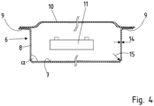
- eine schematische Querschnittsansicht durch die Batteriewanne.
- In den Figuren werden für gleiche Bauteile dieselben Bezugszeichen verwendet, auch eine wiederholte Beschreibung aus Vereinfachungsgründen entfällt.
-
Figur 1 zeigt das erfindungsgemäße Verfahren. Zunächst wird in einer Warmformlinie 1 eine Platine 2 bereitgestellt. Die Platine 2 wird in einer Ofeneinrichtung 3 erwärmt und als erwärmte Platine 4 dann in eine Umformeinrichtung 5, insbesondere in ein Warmumformpresshärtewerkzeug, eingelegt. Nach Abschluss des Umformvorganges kann dann die so hergestellte Batteriewanne 6 entnommen. Die Batteriewanne 6 selbst ist inFigur 2 in perspektivischer Ansicht dargestellt. Diese weist einen Boden 7 auf, von dem Boden 7 umseitig sich erstreckende Seitenwände 8 sowie umlaufend von Seitenwänden 8 nach außen abstehend ein Flansch 9. Der Flansch 9 dient gemäßFigur 3 dargestellt zur Koppelung mit einem Deckel 10. Im Inneren der so angeordneten Batteriewanne 6 sind dann Batteriespeicher in Form von Akkus 11 bzw. einzelnen Batteriezellen angeordnet. In dem Boden 7 können einstückig und werkstoffeinheitlich Versteifungssicken 12 ausgebildet sein, die sich hier in Kraftfahrzeugquerrichtung Y erstrecken. Im Fall eines Seitencrashs ist somit eine höhere Steifigkeit ausgebildet. Innerhalb der Batterieträgers können beispielsweise Längsträger 13 angeordnet sein. Die Längsträger 13 dienten dann als Aufnahme, beispielsweise als Anschraubpunkte für die Akkumulatoren dienen. - Gemäß der schematischen Längsschnittansicht von
Figur 4 ist ein Winkel α zwischen Boden 7 und Seitenwand 8 ausgebildet, zwischen 80° und 90°, insbesondere bei ca. 85°. Hierdurch keine optimale Entnahme aus dem Warmumformwerkzeug nach Abschluss des Presshärtevorganges sichergestellt werden. Es ergibt sich ein Verhältnis von Wandstärke 14 zu Radius 15, von 5 bis 10. Dies bedeutet der Radius 15 ist ca. 5mal bis 10mal so groß im Vergleich zu der Wandstärke 14 der Batteriewanne 6. Ein analoger Winkel sowie auch Radius 15 ergibt sich dann im Übergang von Seitenwand 8 zu Flansch 9. Nicht näher dargestellt sind Lochungen innerhalb des Flansches 9 bzw. ein Randbeschnitt des Flansches 9, welches ebenfalls in dem Warmumformpresshärtewerkzeug gemäßFigur 1 durchgeführt werden kann. Jedoch auch in einem Folgeverbundwerkzeug durchgeführt werden kann. -
- 1 -
- Warmumformlinie
- 2 -
- Platine
- 3 -
- erwärmte Platine
- 4 -
- Ofeneinrichtung
- 5 -
- Warmumform- und Presshärtewerkzeug
- 6 -
- Batteriewanne
- 7 -
- Boden
- 8 -
- Seitenwand
- 9 -
- Flansch
- 10 -
- Deckel
- 11 -
- Akku
- 12-
- Sicke
- 13 -
- Längsträger
- 14 -
- Wandstärke
- 15 -
- Radius
- Y -
- Kraftfahrzeugquerrichtung
- α -
- Winkel
Claims (10)
- Verfahren zur Herstellung einer Batteriewanne (6) für einen Batterieträger eines Kraftfahrzeuges, gekennzeichnet durch folgende Verfahrensschritte:• Bereitstellen einer Platine (2) aus einer härtbaren Stahlblechlegierung, optional ist die Platine (2) vorbeschichtet,• Vollständiges Erwärmen auf eine Temperatur größer AC1, insbesondere größer AC3,• Warmumformen und Presshärten der Platine (2), zu einer Batteriewanne (6) mit einem flächigen Boden (7), davon umlaufend abstehenden Seitenwänden (8) und von den Seitenwänden (8) umlaufend abstehendem nach außen orientiertem Flansch (9),• Randbeschnitt und/oder Lochen der Platine (2) und/oder der umgeformten Batteriewanne (6) bei einer Temperatur zwischen 400° und 700° C,• Einstellen einer Zugfestigkeit zwischen 350 und 850MPa.
- Verfahren nach Anspruch 1, dadurch gekennzeichnet, dass eine Stahllegierung mit folgenden Legierungsbestandteilen, ausgedrückt in Gewichtsprozent verwendet wird, Rest Eisen und erschmelzungsbedingte Verunreinigungen:
C min. 0,06 max. 0,13 bevorzugt min. 0,07 max. 0,11 Si max. 0,7 bevorzugt min. 0,02 max. 0,5 Mn max. 1,8 bevorzugt min. 1,2 max. 1,7 P max. 0,05 bevorzugt max. 0,03 S max. 0,05 bevorzugt max. 0,01 Al max. 0,1 bevorzugt min. 0,02 max. 0,07 Cu max. 0,2 Ti max. 1,2 bevorzugt min. 0,03 bis 0,2 Nb max. 0,1 % bevorzugt 0,04 - 0,1 % B max. 0,003 % bevorzugt 0,007 bis 0,002 % Cr max. 0,15 % Mo. max. 0,1 % V max. 0,1 % - Verfahren nach Anspruch 1 oder 2, dadurch gekennzeichnet, dass als Beschichtung eine Al/Si oder ein Zn Beschichtung verwendet wird.
- Verfahren nach einem der Ansprüche 1 bis 3, dadurch gekennzeichnet, dass eine Dehngrenze A50 von 6 bis 20% eingestellt wird, vorzugsweise von 10 bis 18%, insbesondere von 12 bis 16%.
- Verfahren nach einem der vorgenannten Ansprüche, dadurch gekennzeichnet, dass eine Blechdicke der Platine (2) zwischen 0,5 und 2,5mm, vorzugsweise zwischen 1 und 2mm verwendet wird.
- Verfahren nach einem der vorgenannten Ansprüche, dadurch gekennzeichnet, dass die Batteriewanne (6) in Draufsicht eine rechteckförmige Konfiguration aufweist.
- Verfahren nach einem der vorgenannten Ansprüche, dadurch gekennzeichnet, dass die Platine (2) Abmessungen von größer 1300mm × 1800mm aufweist.
- Verfahren nach einem der vorgenannten Ansprüche, dadurch gekennzeichnet, dass ein Radius (15) zu Wandstärkenverhältnis (14) von 5 bis 10 eingestellt wird.
- Verfahren nach einem der vorgenannten Ansprüche, dadurch gekennzeichnet, dass im Boden (7) Versteifungssicken (12) werkstoffeinheitlich und einstückig ausgebildet werden.
- Verfahren nach einem der vorgenannten Ansprüche, dadurch gekennzeichnet, dass die Batteriewanne nach dem Warmumformen beschichtet, insbesondere KTL-lackiert oder pulverlackiert wird.
Priority Applications (2)
| Application Number | Priority Date | Filing Date | Title |
|---|---|---|---|
| EP22188578.3A EP4318760A1 (de) | 2022-08-03 | 2022-08-03 | Verfahren zur herstellung einer batteriewanne für ein kraftfahrzeug |
| CN202310969274.0A CN117506327A (zh) | 2022-08-03 | 2023-08-03 | 用于制造用于机动车的电池支架的电池槽的方法 |
Applications Claiming Priority (1)
| Application Number | Priority Date | Filing Date | Title |
|---|---|---|---|
| EP22188578.3A EP4318760A1 (de) | 2022-08-03 | 2022-08-03 | Verfahren zur herstellung einer batteriewanne für ein kraftfahrzeug |
Publications (1)
| Publication Number | Publication Date |
|---|---|
| EP4318760A1 true EP4318760A1 (de) | 2024-02-07 |
Family
ID=82786700
Family Applications (1)
| Application Number | Title | Priority Date | Filing Date |
|---|---|---|---|
| EP22188578.3A Pending EP4318760A1 (de) | 2022-08-03 | 2022-08-03 | Verfahren zur herstellung einer batteriewanne für ein kraftfahrzeug |
Country Status (2)
| Country | Link |
|---|---|
| EP (1) | EP4318760A1 (de) |
| CN (1) | CN117506327A (de) |
Cited By (3)
| Publication number | Priority date | Publication date | Assignee | Title |
|---|---|---|---|---|
| EP4631754A1 (de) * | 2024-04-08 | 2025-10-15 | Benteler Automobiltechnik GmbH | Warmgeformte und pressgehärtete batteriewanne |
| WO2025214575A1 (de) * | 2024-04-08 | 2025-10-16 | Benteler Automobiltechnik Gmbh | Batterieeinhausung |
| EP4663320A1 (de) * | 2024-06-11 | 2025-12-17 | Benteler Automobiltechnik GmbH | Warmgeformte batteriewanne mit weichen eckbereichen |
Citations (3)
| Publication number | Priority date | Publication date | Assignee | Title |
|---|---|---|---|---|
| EP1516938A1 (de) * | 2002-06-19 | 2005-03-23 | Nippon Steel Corporation | Stahl für rohöltank und herstellungsverfahren dafür, rohöltank und korrosionsschutzverfahren dafür |
| DE102017102699A1 (de) * | 2017-02-10 | 2018-08-16 | Benteler Automobiltechnik Gmbh | Batterieträger mit verbesserten Crasheigenschaften |
| EP3544082A1 (de) * | 2018-03-19 | 2019-09-25 | Muhr und Bender KG | Gehäuseanordnung zur aufnahme elektrischer speichermittel und verfahren zur herstellung einer gehäuseanordnung |
Family Cites Families (3)
| Publication number | Priority date | Publication date | Assignee | Title |
|---|---|---|---|---|
| DE102016108836B4 (de) * | 2016-05-12 | 2018-05-24 | Benteler Automobiltechnik Gmbh | Kraftfahrzeugbauteil sowie Verfahren zu dessen Herstellung |
| CN111293246B (zh) * | 2020-02-21 | 2022-05-20 | 苏州宝优际科技股份有限公司 | 基于热成型工艺的新能源汽车动力电池壳体生产方法 |
| DE102020116126A1 (de) * | 2020-06-18 | 2021-12-23 | Bilstein Gmbh & Co. Kg | Verfahren zum Presshärten von warmumformbaren Platinen |
-
2022
- 2022-08-03 EP EP22188578.3A patent/EP4318760A1/de active Pending
-
2023
- 2023-08-03 CN CN202310969274.0A patent/CN117506327A/zh active Pending
Patent Citations (3)
| Publication number | Priority date | Publication date | Assignee | Title |
|---|---|---|---|---|
| EP1516938A1 (de) * | 2002-06-19 | 2005-03-23 | Nippon Steel Corporation | Stahl für rohöltank und herstellungsverfahren dafür, rohöltank und korrosionsschutzverfahren dafür |
| DE102017102699A1 (de) * | 2017-02-10 | 2018-08-16 | Benteler Automobiltechnik Gmbh | Batterieträger mit verbesserten Crasheigenschaften |
| EP3544082A1 (de) * | 2018-03-19 | 2019-09-25 | Muhr und Bender KG | Gehäuseanordnung zur aufnahme elektrischer speichermittel und verfahren zur herstellung einer gehäuseanordnung |
Cited By (3)
| Publication number | Priority date | Publication date | Assignee | Title |
|---|---|---|---|---|
| EP4631754A1 (de) * | 2024-04-08 | 2025-10-15 | Benteler Automobiltechnik GmbH | Warmgeformte und pressgehärtete batteriewanne |
| WO2025214575A1 (de) * | 2024-04-08 | 2025-10-16 | Benteler Automobiltechnik Gmbh | Batterieeinhausung |
| EP4663320A1 (de) * | 2024-06-11 | 2025-12-17 | Benteler Automobiltechnik GmbH | Warmgeformte batteriewanne mit weichen eckbereichen |
Also Published As
| Publication number | Publication date |
|---|---|
| CN117506327A (zh) | 2024-02-06 |
Similar Documents
| Publication | Publication Date | Title |
|---|---|---|
| DE102017102699B4 (de) | Batterieträger mit verbesserten Crasheigenschaften | |
| EP1646459B2 (de) | Verfahren zur herstellung eines pressgehärteten bauteils | |
| EP2848709B1 (de) | Verfahren zum Herstellen eines mit einem metallischen, vor Korrosion schützenden Überzug versehenen Stahlbauteils und Stahlbauteil | |
| EP2553133B1 (de) | Stahl, stahlflachprodukt, stahlbauteil und verfahren zur herstellung eines stahlbauteils | |
| DE69935125T3 (de) | Hochfestes, kaltgewalztes Stahlblech und Verfahren zu dessen Herstellung | |
| DE102017102685B4 (de) | Batterieträger mit einer tiefgezogenen Wanne aus Aluminiumsowie Verfahren zu dessen Herstellung | |
| EP3895230B1 (de) | Batteriegehäuse und verwendung | |
| EP1646458A1 (de) | Pressgehärtetes bauteil und verfahren zu seiner herstellung | |
| EP3625835B1 (de) | Batteriegehäuse | |
| DE102010051745B4 (de) | PKW mit Schutzbauteil | |
| DE102011053941A1 (de) | Verfahren zum Erzeugen gehärteter Bauteile mit Bereichen unterschiedlicher Härte und/oder Duktilität | |
| DE102018101735A1 (de) | Zweistufige warmumformung von stahl | |
| KR102884264B1 (ko) | 전기차를 위한 배터리 박스 저부 부분 | |
| CN117506327A (zh) | 用于制造用于机动车的电池支架的电池槽的方法 | |
| WO2011023499A1 (de) | Korrosionsgeschützte geschweisste blechplatine für ein kraftfahrzeug und deren herstellungsverfahren | |
| DE102012024626A1 (de) | Fahrzeugkarosserie und Verfahren zur Fertigung eines Formteils dafür | |
| EP3365469B1 (de) | Verfahren zum herstellen eines stahlbauteils für ein fahrzeug | |
| DE102015119417A1 (de) | Kontrolle von flüssigmetall-versprödung in galvanisierten, pressgehärteten komponeten | |
| DE102023117221A1 (de) | Montagestruktur für ein elektrofahrzeug | |
| EP2581466B1 (de) | Verfahren zur Herstellung eines Formteils | |
| EP3625045A1 (de) | Warmumformmaterial, bauteil und verwendung | |
| DE102023124894B4 (de) | Fahrzeugbodenblechanordnung | |
| DE102008014914B4 (de) | Strukturteil für eine Fahrzeug-Panzerung | |
| EP4663320B1 (de) | Warmgeformte batteriewanne mit weichen eckbereichen | |
| EP4631754B1 (de) | Warmgeformte und pressgehärtete batteriewanne |
Legal Events
| Date | Code | Title | Description |
|---|---|---|---|
| PUAI | Public reference made under article 153(3) epc to a published international application that has entered the european phase |
Free format text: ORIGINAL CODE: 0009012 |
|
| STAA | Information on the status of an ep patent application or granted ep patent |
Free format text: STATUS: REQUEST FOR EXAMINATION WAS MADE |
|
| 17P | Request for examination filed |
Effective date: 20230508 |
|
| AK | Designated contracting states |
Kind code of ref document: A1 Designated state(s): AL AT BE BG CH CY CZ DE DK EE ES FI FR GB GR HR HU IE IS IT LI LT LU LV MC MK MT NL NO PL PT RO RS SE SI SK SM TR |