EP4318721A1 - Battery and electronic device applying same - Google Patents
Battery and electronic device applying same Download PDFInfo
- Publication number
- EP4318721A1 EP4318721A1 EP21933691.4A EP21933691A EP4318721A1 EP 4318721 A1 EP4318721 A1 EP 4318721A1 EP 21933691 A EP21933691 A EP 21933691A EP 4318721 A1 EP4318721 A1 EP 4318721A1
- Authority
- EP
- European Patent Office
- Prior art keywords
- wall body
- electrode plate
- active substance
- substance layer
- conductive member
- Prior art date
- Legal status (The legal status is an assumption and is not a legal conclusion. Google has not performed a legal analysis and makes no representation as to the accuracy of the status listed.)
- Pending
Links
- 239000013543 active substance Substances 0.000 claims abstract description 127
- 238000009413 insulation Methods 0.000 claims abstract description 60
- 239000012774 insulation material Substances 0.000 claims description 28
- 239000011245 gel electrolyte Substances 0.000 claims description 4
- 239000007784 solid electrolyte Substances 0.000 claims description 4
- 239000011248 coating agent Substances 0.000 description 10
- 238000000576 coating method Methods 0.000 description 10
- 239000002390 adhesive tape Substances 0.000 description 9
- 239000000463 material Substances 0.000 description 7
- WHXSMMKQMYFTQS-UHFFFAOYSA-N Lithium Chemical compound [Li] WHXSMMKQMYFTQS-UHFFFAOYSA-N 0.000 description 6
- 229910052744 lithium Inorganic materials 0.000 description 6
- 229920001940 conductive polymer Polymers 0.000 description 5
- 239000007769 metal material Substances 0.000 description 5
- 229910001416 lithium ion Inorganic materials 0.000 description 3
- -1 lithium-ion compound Chemical class 0.000 description 3
- 239000007773 negative electrode material Substances 0.000 description 3
- 239000007774 positive electrode material Substances 0.000 description 3
- OKTJSMMVPCPJKN-UHFFFAOYSA-N Carbon Chemical compound [C] OKTJSMMVPCPJKN-UHFFFAOYSA-N 0.000 description 2
- WMFOQBRAJBCJND-UHFFFAOYSA-M Lithium hydroxide Chemical compound [Li+].[OH-] WMFOQBRAJBCJND-UHFFFAOYSA-M 0.000 description 2
- CPLXHLVBOLITMK-UHFFFAOYSA-N Magnesium oxide Chemical compound [Mg]=O CPLXHLVBOLITMK-UHFFFAOYSA-N 0.000 description 2
- 239000002033 PVDF binder Substances 0.000 description 2
- 229920003171 Poly (ethylene oxide) Polymers 0.000 description 2
- 239000004721 Polyphenylene oxide Substances 0.000 description 2
- VYPSYNLAJGMNEJ-UHFFFAOYSA-N Silicium dioxide Chemical compound O=[Si]=O VYPSYNLAJGMNEJ-UHFFFAOYSA-N 0.000 description 2
- GWEVSGVZZGPLCZ-UHFFFAOYSA-N Titan oxide Chemical compound O=[Ti]=O GWEVSGVZZGPLCZ-UHFFFAOYSA-N 0.000 description 2
- RTAQQCXQSZGOHL-UHFFFAOYSA-N Titanium Chemical compound [Ti] RTAQQCXQSZGOHL-UHFFFAOYSA-N 0.000 description 2
- MCMNRKCIXSYSNV-UHFFFAOYSA-N Zirconium dioxide Chemical compound O=[Zr]=O MCMNRKCIXSYSNV-UHFFFAOYSA-N 0.000 description 2
- 239000000853 adhesive Substances 0.000 description 2
- 230000001070 adhesive effect Effects 0.000 description 2
- 239000000919 ceramic Substances 0.000 description 2
- 238000010586 diagram Methods 0.000 description 2
- 239000011521 glass Substances 0.000 description 2
- XLYOFNOQVPJJNP-UHFFFAOYSA-M hydroxide Chemical compound [OH-] XLYOFNOQVPJJNP-UHFFFAOYSA-M 0.000 description 2
- PQXKHYXIUOZZFA-UHFFFAOYSA-M lithium fluoride Chemical compound [Li+].[F-] PQXKHYXIUOZZFA-UHFFFAOYSA-M 0.000 description 2
- 229910001386 lithium phosphate Inorganic materials 0.000 description 2
- 229920003229 poly(methyl methacrylate) Polymers 0.000 description 2
- 229920002239 polyacrylonitrile Polymers 0.000 description 2
- 239000002861 polymer material Substances 0.000 description 2
- 239000004926 polymethyl methacrylate Substances 0.000 description 2
- 229920006380 polyphenylene oxide Polymers 0.000 description 2
- 229920000379 polypropylene carbonate Polymers 0.000 description 2
- 229920002981 polyvinylidene fluoride Polymers 0.000 description 2
- XOLBLPGZBRYERU-UHFFFAOYSA-N tin dioxide Chemical compound O=[Sn]=O XOLBLPGZBRYERU-UHFFFAOYSA-N 0.000 description 2
- TWQULNDIKKJZPH-UHFFFAOYSA-K trilithium;phosphate Chemical compound [Li+].[Li+].[Li+].[O-]P([O-])([O-])=O TWQULNDIKKJZPH-UHFFFAOYSA-K 0.000 description 2
- 229910007959 Li1+x+y(Al,Ga)x(Ti,Ge)2−xSiyP3-yO12 Inorganic materials 0.000 description 1
- FUJCRWPEOMXPAD-UHFFFAOYSA-N Li2O Inorganic materials [Li+].[Li+].[O-2] FUJCRWPEOMXPAD-UHFFFAOYSA-N 0.000 description 1
- 229910012107 Li3+xLa3M2O12 Inorganic materials 0.000 description 1
- 229910010092 LiAlO2 Inorganic materials 0.000 description 1
- HBBGRARXTFLTSG-UHFFFAOYSA-N Lithium ion Chemical compound [Li+] HBBGRARXTFLTSG-UHFFFAOYSA-N 0.000 description 1
- 229910018413 LixAlyTiz(PO4)3 Inorganic materials 0.000 description 1
- 229910016838 LixGeyPzSw Inorganic materials 0.000 description 1
- 229910016983 LixLayTiO3 Inorganic materials 0.000 description 1
- 229910014694 LixTiy(PO4)3 Inorganic materials 0.000 description 1
- PWHULOQIROXLJO-UHFFFAOYSA-N Manganese Chemical compound [Mn] PWHULOQIROXLJO-UHFFFAOYSA-N 0.000 description 1
- MKGYHFFYERNDHK-UHFFFAOYSA-K P(=O)([O-])([O-])[O-].[Ti+4].[Li+] Chemical compound P(=O)([O-])([O-])[O-].[Ti+4].[Li+] MKGYHFFYERNDHK-UHFFFAOYSA-K 0.000 description 1
- PPVYRCKAOVCGRJ-UHFFFAOYSA-K P(=S)([O-])([O-])[O-].[Ge+2].[Li+] Chemical compound P(=S)([O-])([O-])[O-].[Ge+2].[Li+] PPVYRCKAOVCGRJ-UHFFFAOYSA-K 0.000 description 1
- 229910019142 PO4 Inorganic materials 0.000 description 1
- 229910020343 SiS2 Inorganic materials 0.000 description 1
- 229910002370 SrTiO3 Inorganic materials 0.000 description 1
- PFYQFCKUASLJLL-UHFFFAOYSA-N [Co].[Ni].[Li] Chemical compound [Co].[Ni].[Li] PFYQFCKUASLJLL-UHFFFAOYSA-N 0.000 description 1
- HFCVPDYCRZVZDF-UHFFFAOYSA-N [Li+].[Co+2].[Ni+2].[O-][Mn]([O-])(=O)=O Chemical compound [Li+].[Co+2].[Ni+2].[O-][Mn]([O-])(=O)=O HFCVPDYCRZVZDF-UHFFFAOYSA-N 0.000 description 1
- YWJVFBOUPMWANA-UHFFFAOYSA-H [Li+].[V+5].[O-]P([O-])([O-])=O.[O-]P([O-])([O-])=O Chemical compound [Li+].[V+5].[O-]P([O-])([O-])=O.[O-]P([O-])([O-])=O YWJVFBOUPMWANA-UHFFFAOYSA-H 0.000 description 1
- 229910045601 alloy Inorganic materials 0.000 description 1
- 239000000956 alloy Substances 0.000 description 1
- WNROFYMDJYEPJX-UHFFFAOYSA-K aluminium hydroxide Chemical compound [OH-].[OH-].[OH-].[Al+3] WNROFYMDJYEPJX-UHFFFAOYSA-K 0.000 description 1
- PNEYBMLMFCGWSK-UHFFFAOYSA-N aluminium oxide Inorganic materials [O-2].[O-2].[O-2].[Al+3].[Al+3] PNEYBMLMFCGWSK-UHFFFAOYSA-N 0.000 description 1
- CVJYOKLQNGVTIS-UHFFFAOYSA-K aluminum;lithium;titanium(4+);phosphate Chemical compound [Li+].[Al+3].[Ti+4].[O-]P([O-])([O-])=O CVJYOKLQNGVTIS-UHFFFAOYSA-K 0.000 description 1
- 229910021383 artificial graphite Inorganic materials 0.000 description 1
- QVQLCTNNEUAWMS-UHFFFAOYSA-N barium oxide Inorganic materials [Ba]=O QVQLCTNNEUAWMS-UHFFFAOYSA-N 0.000 description 1
- 229910001593 boehmite Inorganic materials 0.000 description 1
- ODINCKMPIJJUCX-UHFFFAOYSA-N calcium oxide Inorganic materials [Ca]=O ODINCKMPIJJUCX-UHFFFAOYSA-N 0.000 description 1
- 229910010293 ceramic material Inorganic materials 0.000 description 1
- CETPSERCERDGAM-UHFFFAOYSA-N ceric oxide Chemical compound O=[Ce]=O CETPSERCERDGAM-UHFFFAOYSA-N 0.000 description 1
- 229910000422 cerium(IV) oxide Inorganic materials 0.000 description 1
- 229910052681 coesite Inorganic materials 0.000 description 1
- 229910052593 corundum Inorganic materials 0.000 description 1
- 229910052906 cristobalite Inorganic materials 0.000 description 1
- XUCJHNOBJLKZNU-UHFFFAOYSA-M dilithium;hydroxide Chemical compound [Li+].[Li+].[OH-] XUCJHNOBJLKZNU-UHFFFAOYSA-M 0.000 description 1
- 239000003792 electrolyte Substances 0.000 description 1
- 239000002223 garnet Substances 0.000 description 1
- YBMRDBCBODYGJE-UHFFFAOYSA-N germanium oxide Inorganic materials O=[Ge]=O YBMRDBCBODYGJE-UHFFFAOYSA-N 0.000 description 1
- 229910021389 graphene Inorganic materials 0.000 description 1
- CJNBYAVZURUTKZ-UHFFFAOYSA-N hafnium(IV) oxide Inorganic materials O=[Hf]=O CJNBYAVZURUTKZ-UHFFFAOYSA-N 0.000 description 1
- 229910021385 hard carbon Inorganic materials 0.000 description 1
- FAHBNUUHRFUEAI-UHFFFAOYSA-M hydroxidooxidoaluminium Chemical compound O[Al]=O FAHBNUUHRFUEAI-UHFFFAOYSA-M 0.000 description 1
- 150000002500 ions Chemical class 0.000 description 1
- 229910000664 lithium aluminum titanium phosphates (LATP) Inorganic materials 0.000 description 1
- 229910052808 lithium carbonate Inorganic materials 0.000 description 1
- XGZVUEUWXADBQD-UHFFFAOYSA-L lithium carbonate Chemical compound [Li+].[Li+].[O-]C([O-])=O XGZVUEUWXADBQD-UHFFFAOYSA-L 0.000 description 1
- 229910000625 lithium cobalt oxide Inorganic materials 0.000 description 1
- GELKBWJHTRAYNV-UHFFFAOYSA-K lithium iron phosphate Chemical compound [Li+].[Fe+2].[O-]P([O-])([O-])=O GELKBWJHTRAYNV-UHFFFAOYSA-K 0.000 description 1
- 229910000659 lithium lanthanum titanates (LLT) Inorganic materials 0.000 description 1
- IDBFBDSKYCUNPW-UHFFFAOYSA-N lithium nitride Chemical compound [Li]N([Li])[Li] IDBFBDSKYCUNPW-UHFFFAOYSA-N 0.000 description 1
- DVATZODUVBMYHN-UHFFFAOYSA-K lithium;iron(2+);manganese(2+);phosphate Chemical compound [Li+].[Mn+2].[Fe+2].[O-]P([O-])([O-])=O DVATZODUVBMYHN-UHFFFAOYSA-K 0.000 description 1
- BFZPBUKRYWOWDV-UHFFFAOYSA-N lithium;oxido(oxo)cobalt Chemical compound [Li+].[O-][Co]=O BFZPBUKRYWOWDV-UHFFFAOYSA-N 0.000 description 1
- VTHJTEIRLNZDEV-UHFFFAOYSA-L magnesium dihydroxide Chemical compound [OH-].[OH-].[Mg+2] VTHJTEIRLNZDEV-UHFFFAOYSA-L 0.000 description 1
- 229910001862 magnesium hydroxide Inorganic materials 0.000 description 1
- 239000000347 magnesium hydroxide Substances 0.000 description 1
- LBSANEJBGMCTBH-UHFFFAOYSA-N manganate Chemical compound [O-][Mn]([O-])(=O)=O LBSANEJBGMCTBH-UHFFFAOYSA-N 0.000 description 1
- 229910052748 manganese Inorganic materials 0.000 description 1
- 239000011572 manganese Substances 0.000 description 1
- 229910052751 metal Inorganic materials 0.000 description 1
- 239000002184 metal Substances 0.000 description 1
- 229910021382 natural graphite Inorganic materials 0.000 description 1
- GNRSAWUEBMWBQH-UHFFFAOYSA-N nickel(II) oxide Inorganic materials [Ni]=O GNRSAWUEBMWBQH-UHFFFAOYSA-N 0.000 description 1
- NBIIXXVUZAFLBC-UHFFFAOYSA-K phosphate Chemical compound [O-]P([O-])([O-])=O NBIIXXVUZAFLBC-UHFFFAOYSA-K 0.000 description 1
- 239000010452 phosphate Substances 0.000 description 1
- 229920000131 polyvinylidene Polymers 0.000 description 1
- 239000000377 silicon dioxide Substances 0.000 description 1
- 239000002210 silicon-based material Substances 0.000 description 1
- 229910021384 soft carbon Inorganic materials 0.000 description 1
- 239000007787 solid Substances 0.000 description 1
- 229910052682 stishovite Inorganic materials 0.000 description 1
- 239000000126 substance Substances 0.000 description 1
- 239000011366 tin-based material Substances 0.000 description 1
- 229910052905 tridymite Inorganic materials 0.000 description 1
- 125000005287 vanadyl group Chemical group 0.000 description 1
- 229910001845 yogo sapphire Inorganic materials 0.000 description 1
- RUDFQVOCFDJEEF-UHFFFAOYSA-N yttrium(III) oxide Inorganic materials [O-2].[O-2].[O-2].[Y+3].[Y+3] RUDFQVOCFDJEEF-UHFFFAOYSA-N 0.000 description 1
- XLOMVQKBTHCTTD-UHFFFAOYSA-N zinc oxide Inorganic materials [Zn]=O XLOMVQKBTHCTTD-UHFFFAOYSA-N 0.000 description 1
Images


Classifications
-
- H—ELECTRICITY
- H01—ELECTRIC ELEMENTS
- H01M—PROCESSES OR MEANS, e.g. BATTERIES, FOR THE DIRECT CONVERSION OF CHEMICAL ENERGY INTO ELECTRICAL ENERGY
- H01M50/00—Constructional details or processes of manufacture of the non-active parts of electrochemical cells other than fuel cells, e.g. hybrid cells
- H01M50/50—Current conducting connections for cells or batteries
- H01M50/531—Electrode connections inside a battery casing
- H01M50/533—Electrode connections inside a battery casing characterised by the shape of the leads or tabs
-
- H—ELECTRICITY
- H01—ELECTRIC ELEMENTS
- H01M—PROCESSES OR MEANS, e.g. BATTERIES, FOR THE DIRECT CONVERSION OF CHEMICAL ENERGY INTO ELECTRICAL ENERGY
- H01M10/00—Secondary cells; Manufacture thereof
- H01M10/04—Construction or manufacture in general
- H01M10/0422—Cells or battery with cylindrical casing
- H01M10/0427—Button cells
-
- H—ELECTRICITY
- H01—ELECTRIC ELEMENTS
- H01M—PROCESSES OR MEANS, e.g. BATTERIES, FOR THE DIRECT CONVERSION OF CHEMICAL ENERGY INTO ELECTRICAL ENERGY
- H01M10/00—Secondary cells; Manufacture thereof
- H01M10/05—Accumulators with non-aqueous electrolyte
- H01M10/052—Li-accumulators
- H01M10/0525—Rocking-chair batteries, i.e. batteries with lithium insertion or intercalation in both electrodes; Lithium-ion batteries
-
- H—ELECTRICITY
- H01—ELECTRIC ELEMENTS
- H01M—PROCESSES OR MEANS, e.g. BATTERIES, FOR THE DIRECT CONVERSION OF CHEMICAL ENERGY INTO ELECTRICAL ENERGY
- H01M4/00—Electrodes
- H01M4/02—Electrodes composed of, or comprising, active material
- H01M4/64—Carriers or collectors
- H01M4/70—Carriers or collectors characterised by shape or form
- H01M4/76—Containers for holding the active material, e.g. tubes, capsules
-
- H—ELECTRICITY
- H01—ELECTRIC ELEMENTS
- H01M—PROCESSES OR MEANS, e.g. BATTERIES, FOR THE DIRECT CONVERSION OF CHEMICAL ENERGY INTO ELECTRICAL ENERGY
- H01M50/00—Constructional details or processes of manufacture of the non-active parts of electrochemical cells other than fuel cells, e.g. hybrid cells
- H01M50/10—Primary casings; Jackets or wrappings
- H01M50/102—Primary casings; Jackets or wrappings characterised by their shape or physical structure
- H01M50/109—Primary casings; Jackets or wrappings characterised by their shape or physical structure of button or coin shape
-
- H—ELECTRICITY
- H01—ELECTRIC ELEMENTS
- H01M—PROCESSES OR MEANS, e.g. BATTERIES, FOR THE DIRECT CONVERSION OF CHEMICAL ENERGY INTO ELECTRICAL ENERGY
- H01M50/00—Constructional details or processes of manufacture of the non-active parts of electrochemical cells other than fuel cells, e.g. hybrid cells
- H01M50/40—Separators; Membranes; Diaphragms; Spacing elements inside cells
- H01M50/46—Separators, membranes or diaphragms characterised by their combination with electrodes
-
- H—ELECTRICITY
- H01—ELECTRIC ELEMENTS
- H01M—PROCESSES OR MEANS, e.g. BATTERIES, FOR THE DIRECT CONVERSION OF CHEMICAL ENERGY INTO ELECTRICAL ENERGY
- H01M50/00—Constructional details or processes of manufacture of the non-active parts of electrochemical cells other than fuel cells, e.g. hybrid cells
- H01M50/50—Current conducting connections for cells or batteries
- H01M50/543—Terminals
- H01M50/545—Terminals formed by the casing of the cells
-
- H—ELECTRICITY
- H01—ELECTRIC ELEMENTS
- H01M—PROCESSES OR MEANS, e.g. BATTERIES, FOR THE DIRECT CONVERSION OF CHEMICAL ENERGY INTO ELECTRICAL ENERGY
- H01M2220/00—Batteries for particular applications
- H01M2220/30—Batteries in portable systems, e.g. mobile phone, laptop
-
- Y—GENERAL TAGGING OF NEW TECHNOLOGICAL DEVELOPMENTS; GENERAL TAGGING OF CROSS-SECTIONAL TECHNOLOGIES SPANNING OVER SEVERAL SECTIONS OF THE IPC; TECHNICAL SUBJECTS COVERED BY FORMER USPC CROSS-REFERENCE ART COLLECTIONS [XRACs] AND DIGESTS
- Y02—TECHNOLOGIES OR APPLICATIONS FOR MITIGATION OR ADAPTATION AGAINST CLIMATE CHANGE
- Y02E—REDUCTION OF GREENHOUSE GAS [GHG] EMISSIONS, RELATED TO ENERGY GENERATION, TRANSMISSION OR DISTRIBUTION
- Y02E60/00—Enabling technologies; Technologies with a potential or indirect contribution to GHG emissions mitigation
- Y02E60/10—Energy storage using batteries
-
- Y—GENERAL TAGGING OF NEW TECHNOLOGICAL DEVELOPMENTS; GENERAL TAGGING OF CROSS-SECTIONAL TECHNOLOGIES SPANNING OVER SEVERAL SECTIONS OF THE IPC; TECHNICAL SUBJECTS COVERED BY FORMER USPC CROSS-REFERENCE ART COLLECTIONS [XRACs] AND DIGESTS
- Y02—TECHNOLOGIES OR APPLICATIONS FOR MITIGATION OR ADAPTATION AGAINST CLIMATE CHANGE
- Y02P—CLIMATE CHANGE MITIGATION TECHNOLOGIES IN THE PRODUCTION OR PROCESSING OF GOODS
- Y02P70/00—Climate change mitigation technologies in the production process for final industrial or consumer products
- Y02P70/50—Manufacturing or production processes characterised by the final manufactured product
Definitions
- This application relates to the electrochemical field, and in particular, to a battery and an electronic apparatus using such battery.
- Lithium-ion batteries have been widely applied in the field of consumer electronics due to their advantages such as large specific energy, high working voltage, low self-discharge rate, a small size, and a light weight.
- advantages such as large specific energy, high working voltage, low self-discharge rate, a small size, and a light weight.
- people have increasingly high demands for energy density of a battery.
- This application provides a battery, including a housing, an insulation member, and a first active substance layer and a second active substance layer that have opposite polarities.
- the housing includes a first wall body, a second wall body, and a third wall body, the first wall body is conductive and disposed opposite to the third wall body, and the second wall body is connected to the first wall body and the third wall body to enclose an accommodating cavity in conjunction with the first wall body and the third wall body.
- the insulation member, the first active substance layer, and the second active substance layer are accommodated in the accommodating cavity.
- the second active substance layer is disposed on a surface of the first wall body that faces the third wall body.
- the first active substance layer is disposed between the second active substance layer and the third wall body.
- the insulation member is disposed between the first active substance layer and the second active substance layer.
- the third wall body is a conductive wall body
- the first active substance layer is disposed on a surface of the third wall body that faces the first wall body
- the third wall body is insulated from the first wall body
- the insulation element is disposed between the third wall body and the second wall body.
- the battery further includes a first electrode plate and a second electrode plate that are accommodated in the accommodating cavity; the first electrode plate includes a first current collector and the first active substance layer disposed on a surface of the first current collector, and the second electrode plate includes a second current collector and the second active substance layer disposed on a surface of the second current collector; and the first electrode plate is disposed between the first wall body and the third wall body, and the second electrode plate is disposed between the first electrode plate and the third wall body.
- the first current collector is electrically connected to the third wall body through a first conductive member, and the first conductive member is insulated from the second electrode plate.
- the first wall body is electrically connected to the second current collector through a second conductive member, and the second conductive member is insulated from the first electrode plate; or the first wall body is electrically connected to the second current collector through the conductive second wall body, and the second wall body is insulated from the first electrode plate.
- the first conductive member penetrates through the second electrode plate in a first direction, and an insulation material is disposed between the first conductive member and the second electrode plate.
- the first conductive member is a hollow cylinder with sealed ends.
- the insulation member is disposed between the first electrode plate and the second wall body.
- the third wall body is a conductive wall body, and the second active substance layer is further disposed on a surface of the third wall body that faces the first wall body; and the battery further includes a first electrode plate accommodated in the accommodating cavity, and the first electrode plate includes a first current collector and the first active substance layer disposed on a surface of the first current collector.
- the battery further includes a first conductive member, the first current collector is electrically connected to the first conductive member, the first conductive member is extended from the third wall body, and the first conductive member is insulated from the third wall body; and the first wall body is electrically connected to the third wall body through the conductive second wall body, and the second wall body is insulated from the first electrode plate.
- the first conductive member penetrates through the third wall body in a first direction, and an insulation material is disposed between the first conductive member and the third wall body.
- the battery further includes a second electrode plate and a third electrode plate that are accommodated in the accommodating cavity.
- the second electrode plate includes a second current collector and the second active substance layer disposed on a surface of the second current collector
- the third electrode plate includes a third current collector and the first active substance layer disposed on a surface of the third current collector.
- the second electrode plate is disposed between the first electrode plate and the first wall body
- the third electrode plate is disposed between the second electrode plate and the first wall body.
- the first conductive member is electrically connected to the third current collector and insulated from the second electrode plate
- the second wall body is electrically connected to the second electrode plate.
- the second wall body is insulated from the third electrode plate.
- the battery further includes a first electrode plate accommodated in the accommodating cavity, the first electrode plate includes a first current collector and the first active substance layer disposed on a surface of the first current collector; and the first electrode plate is separated from the third wall body, the first current collector is electrically connected to the first conductive member, the first conductive member is extended from the third wall body, and the first conductive member is insulated from the third wall body.
- the battery further includes a second electrode plate accommodated in the accommodating cavity, and the second electrode plate includes a second current collector and the second active substance layer disposed on a surface of the second current collector.
- the second electrode plate is disposed between the first electrode plate and the third wall body, the second electrode plate is separated from the third wall body, and the first conductive member is insulated from the second electrode plate.
- the second current collector is electrically connected to the first wall body through a second conductive member, and the second conductive member is insulated from the first electrode plate; or the second current collector is electrically connected to the first wall body through the conductive second wall body, and the second wall body is insulated from the first electrode plate.
- the insulation member includes at least one of a separator, a gel electrolyte, or a solid electrolyte.
- This application provides an electronic apparatus, where the electronic apparatus includes the foregoing battery.
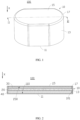
- the second active substance layer is provided on the first wall body, that is, the first wall body serves as a current collector, the housing and internal space thereof are fully used, thereby helping improve energy density of the battery and making the battery thinner.
- a battery 100 includes a housing 10, an insulation member 20, a first active substance layer 30, and a second active substance layer 40.
- the battery 100 may be, but is not limited to, a button cell.
- the housing 10 includes a first wall body 11, a second wall body 13, and a third wall body 15.
- the first wall body 11 is conductive, and the third wall body 15 and the first wall body 11 are opposite each other and spaced apart.
- the second wall body 13 is connected to the first wall body 11 and the third wall body 15 to enclose a sealed accommodating cavity 101 in conjunction with the first wall body 11 and the third wall body 15.
- the conductive first wall body 11 may include a material with a conductive property. In an embodiment, the first wall body 11 may include a metal material. In an embodiment, the first wall body 11 may include a conductive polymer.
- the insulation member 20, the first active substance layer 30, and the second active substance layer 40 are accommodated in the accommodating cavity 101.
- the second active substance layer 40 is disposed on a surface 110 of the first wall body 11 that faces the third wall body 15.
- the first active substance layer 30 and the second active substance layer 40 have opposite polarities, and the first active substance layer 30 is disposed between the third wall body 15 and the second active substance layer 40 that is disposed on the surface 110 of the first wall body 11.
- the insulation member 20 is disposed between the first active substance layer 30 and the second active substance layer 40.
- a material of the insulation member 20 includes at least one of a polymer material with ion conductivity, a lithium-ion compound, an oxide, and a hydroxide.
- the polymer material may be, but is not limited to, one or more of polyvinylidene fluoride-hexafluoropropene (PVDF-HFP), polyvinylidene fluoride (PVDF), polyacrylonitrile (PAN), polymethyl methacrylate (PMMA), polyphenylene oxide (PPO), polypropylene carbonate (PPC), polyethylene oxide (PEO), and a derivative of the preceding substances.
- PVDF-HFP polyvinylidene fluoride-hexafluoropropene
- PVDF polyvinylidene fluoride
- PVDF polyacrylonitrile
- PMMA polymethyl methacrylate
- PPO polyphenylene oxide
- PPC polypropylene carbonate
- PEO polyethylene oxide
- the lithium-ion compound may be selected from, but is not limited to, at least one of lithium phosphate (Li 3 PO 4 ), lithium titanium phosphate (Li x Ti y (PO 4 ) 3 , where 0 ⁇ x ⁇ 2 and 0 ⁇ y ⁇ 3), lithium aluminum titanium phosphate (Li x Al y Ti z (PO 4 ) 3 , where 0 ⁇ x ⁇ 2, 0 ⁇ y ⁇ 1, and 0 ⁇ z ⁇ 3), Li 1+x+y (Al, Ga) x (Ti, Ge) 2-x Si y P 3-y O 12 (0 ⁇ x ⁇ 1 and 0 ⁇ y ⁇ 1), lithium lanthanum titanate (Li x La y TiO 3 , where 0 ⁇ x ⁇ 2 and 0 ⁇ y ⁇ 3), lithium germanium thiophosphate (Li x Ge y P z S w , where 0 ⁇ x ⁇ 4, 0 ⁇ y ⁇ 1, 0 ⁇ z ⁇ 1, and 0 ⁇ w ⁇ 5), lithium nitride (Li
- the oxide may be selected from, but is not limited to, at least one of HfO 2 , SrTiO 3 , SnO 2 , CeO 2 , MgO, NiO, CaO, BaO, ZnO, ZrO 2 , Y 2 O 3 , Al 2 O 3 , TiO 2 , SiO 2 , or the like.
- the hydroxide may be selected from, but is not limited to, at least one of boehmite, magnesium hydroxide, aluminum hydroxide, or the like.
- the insulation member 20 may be at least one of a separator, a gel electrolyte, or a solid electrolyte.
- the gel electrolyte and the solid electrolyte are common types of electrolytes in the battery field and are not limited herein.
- the first active substance layer 30 may be a positive electrode active substance layer or a negative electrode active substance layer.
- the first active substance layer 30 is a positive electrode active substance layer that includes a positive electrode active material; and the second active substance layer 40 is a negative electrode active substance layer that includes a negative electrode active material.
- the first active substance layer 30 is a negative electrode active substance layer that includes a negative electrode active material; and the second active substance layer 40 is a positive electrode active substance layer that includes a positive electrode active material.
- the positive electrode active material may include, but is not limited to, one or more of lithium cobalt oxide, lithium nickel cobalt manganate, lithium nickel cobalt aluminate, lithium manganate oxide, lithium manganese iron phosphate, lithium vanadium phosphate, lithium vanadyl phosphate, lithium iron phosphate, lithium titanate, and a lithium-rich manganese-based material.
- the negative electrode active material may include, but is not limited to, one or more of artificial graphite, natural graphite, soft carbon, hard carbon, graphene, carbonaceous mesophase spherule, a silicon-based material, a tin-based material, lithium titanate, or another metal capable of forming an alloy with lithium.
- the foregoing battery is applied to an electronic apparatus 200, to supply power to the electronic apparatus 200.
- the electronic apparatus 200 may be, but is not limited to, a wearable device (such as a watch), a mobile phone, a toy, a drone, and the like.
- the second active substance layer is a negative electrode active substance layer and the first active substance layer is a positive electrode active substance layer is used for description.
- the third wall body 15 is a conductive wall body.
- the first active substance layer 30 is disposed on a surface 150 of the third wall body 15 that faces the first wall body 11.
- the first wall body 11 is insulated from the third wall body 15.
- the third wall body 15, the first active substance layer 30, the second active substance layer 40, and the first wall body 11 are stacked in a first direction X.
- the first direction X is a direction in which the third wall body 15 faces the first wall body 11 or a direction in which the first wall body 11 faces the third wall body 15.
- the first direction X may be a thickness direction of a battery.
- an insulation element 17 may be provided along a periphery of the third wall body 15, and the insulation element 17 is connected to the third wall body 15 and the second wall body 13, to insulate the first wall body 11 from the third wall body 15.
- the second wall body 13 may be conductive or non-conductive, and the second wall body 13 and the first wall body 11 may be directly or indirectly connected.
- the first wall body 11 and the second wall body 13 may be integrally formed.
- the insulation element 17 may include an insulation adhesive, and the insulation adhesive is filled between the third wall body 15 and the second wall body 13.
- the third wall body 15 may include a material with a conductive property. In an embodiment, the third wall body 15 may include a metal material. In an embodiment, the third wall body 15 may include a conductive polymer.
- a projection of the first active substance layer 30 in the first direction X onto a plane perpendicular to the first direction X is within a projection of the second active substance layer 40 in the first direction X onto a plane perpendicular to the first direction X.
- the first wall body 11 and the third wall body 15 are respectively electrically connected to two electrical connection ends (not shown in the figure) of the electronic apparatus, to supply power to the electronic apparatus.
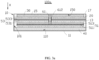
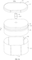
- a battery 100a may further include a first electrode plate 51 and a second electrode plate 53 that have opposite polarities and that are accommodated in the accommodating cavity 101.
- the first electrode plate 51 and the first active substance layer 30 have a same polarity, and the first electrode plate 51 is disposed between the first active substance layer 30 on the surface 150 of the third wall body 15 and the second active substance layer 40 on the surface 110 of the first wall body 11.
- the second electrode plate 53 and the first active substance layer 30 disposed on the surface 150 of the third wall body 15 have opposite polarities, and the second electrode plate 53 is disposed between the first electrode plate 51 and the first active substance layer 30 disposed on the surface 150 of the third wall body 15.
- the insulation members 20 are disposed between the first electrode plate 51 and the second active substance layer 40 disposed on the surface 110 of the first wall body 11, between the first electrode plate 51 and the second electrode plate 53, and between the second electrode plate 53 and the first active substance layer 30 disposed on the surface 150 of the third wall body 15.
- the first electrode plate 51 may be enveloped by the insulation member 20, that is, the insulation member 20 is also disposed between the first electrode plate 51 and the second wall body 13.
- the battery 100a further includes a first conductive member 61, the first electrode plate 51 and the third wall body 15 are electrically connected through the first conductive member 61, and the first conductive member 61 is insulated from the second electrode plate 53.
- the first conductive member 61 may be insulated from the second electrode plate 53 through an insulation material 612.
- the first conductive member 61 and the second electrode plate 53 may be spaced apart to implement insulation.
- a morphology of the first conductive member 61 is not limited, and may be any morphology such as a solid cylinder, a hollow cylinder, or a sheet.
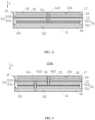
- the first conductive member 61 is a hollow cylinder, and two ends of the first conductive member 61 that are spaced apart in the first direction X may be penetrated through (as shown in FIG. 3a ) or sealed (as shown in FIG. 3c ).
- the first conductive member 61 may penetrate through the second electrode plate 53, and the two ends of the first conductive member 61 that are spaced apart in the first direction X are respectively electrically connected to the first electrode plate 51 and the third wall body 15.
- the insulation material 612 may sleeve or be applied on the first conductive member 61, to insulate the first conductive member 61 from the second electrode plate 53.
- the first conductive member 61 in a hollow cylinder shape helps reduce overall mass of the battery, thereby helping increase energy density of the battery.
- the first conductive member 61 with two ends sealed helps increase a contact area between the first conductive member and a current collector or an external terminal electrically connected to the two ends of the first conductive member, thereby facilitating stability of electrical connection.
- the insulation material 612 may be, but is not limited to, an insulation adhesive tape or an insulation coating.
- the insulation coating may include a ceramic material.
- the second wall body 13 is a conductive wall body, the first electrode plate 51 is insulated from the second wall body 13, and the second electrode plate 53 is electrically connected to the second wall body 13.
- the first electrode plate 51 and the second wall body 13 are spaced apart to implement insulation, and the second electrode plate 53 comes into direct contact with the second wall body 13 to implement electrical connection.
- the first wall body 11 is electrically connected to the second electrode plate 53 through the second wall body 13.
- the second wall body 13 may include a material with a conductive property. In an embodiment, the second wall body 13 may include a metal material. In an embodiment, the second wall body 13 may include a conductive polymer.
- the first electrode plate 51 may include a first current collector 511 and first active substance layers 513 disposed on a surface of the first current collector 511 that faces the first wall body 11 and on a surface of the first current collector 511 that faces the third wall body 15.
- the second electrode plate 53 may include a second current collector 531 and second active substance layers 533 disposed on a surface of the second current collector 531 that faces the first wall body 11 and on a surface of the second current collector 531 that faces the third wall body 15.
- a projection of the first active substance layer 513 in a first direction X onto a plane perpendicular to the first direction X is within a projection of the second active substance layer 533 in the first direction X onto a plane perpendicular to the first direction X, and is within a projection of the second active substance layer 40 in the first direction X onto a plane perpendicular to the first direction X.
- one electrical connection terminal of the electronic apparatus is electrically connected to the first wall body 11 or the second wall body 13, and the other electrical connection terminal is electrically connected to the third wall body 15, so that the battery 100a supplies power to the electronic apparatus.
- a battery 100b further includes a second conductive member 63, the first wall body 11 and the second electrode plate 53 are electrically connected through the second conductive member 63, and the second conductive member 63 is respectively insulated from the first electrode plate 51 and a third wall body 15.
- insulation between the second conductive member 63 and the first electrode plate 51 and between the second conductive member 63 and the third wall body 15 may be implemented through an insulation material 632.
- a morphology of the second conductive member 63 may be the same as or different from that of the first conductive member 61.
- the second conductive member 63 is a hollow cylinder, and two ends of the second conductive member 63 that are spaced apart in the first direction X penetrate through.
- the second conductive member 63 penetrates through the first electrode plate 51, and the two ends of the second conductive member that are spaced apart in the first direction X are respectively electrically connected to the second current collector 531 and the first wall body 11.
- the insulation material 632 may sleeve or be applied on the second conductive member 63, to insulate the second conductive member 63 from the first electrode plate 51.
- the insulation material 632 may be, but is not limited to, an insulation adhesive tape or an insulation coating.
- one electrical connection terminal of the electronic apparatus is electrically connected to the first wall body 11, and the other electrical connection terminal is electrically connected to the third wall body 15, so that the battery 100b supplies power to the electronic apparatus.
- the third wall body 15 is a conductive wall body.
- the second active substance layer 40 is further disposed on the surface 150 of the third wall body 15 that faces the first wall body 11.
- the first direction X is a direction in which the third wall body 15 faces the first wall body 11 or a direction in which the first wall body 11 faces the third wall body 15.
- the first direction X may be a thickness direction of a battery.
- the battery 100c includes a first electrode plate 51a accommodated in an accommodating cavity 101.
- the first electrode plate 51a is located between the second active substance layer 40 disposed on the surface 110 of the first wall body 11 and the second active substance layer 40 disposed on the surface 150 of the third wall body 15.
- the first electrode plate 51a includes a first current collector 511a and the foregoing first active substance layer 30, and the first active substance layer 30 is disposed on a surface of the first current collector 511a.
- the first active substance layer 30 is disposed on a surface of the first current collector 511a that faces the first wall body 11 and on a surface of the first current collector 511a that faces the third wall body 15.
- Insulation members 20 are disposed between the first electrode plate 51a and the second active substance layer 40 disposed on the surface 110 of the first wall body 11, and between the first electrode plate 51a and the second active substance layer 40 disposed on the surface 150 of the third wall body 15.
- the first electrode plate 51a may be enveloped by the insulation member 20.
- the battery 100c further includes a first conductive member 61a, and the first electrode plate 51a is electrically connected to the first conductive member 61a.
- the first conductive member 61a protrudes or is extended from the third wall body 15 (that is, the first conductive member 61a penetrates through the third wall body 15), and the first conductive member 61a is insulated from the third wall body 15.
- the first conductive member 61a may be insulated from the third wall body 15 through an insulation material 612a.
- the first conductive member 61a is a hollow cylinder, and of two ends of the first conductive member that are spaced apart in a first direction X, one end is electrically connected to the first current collector 511a, and the other end penetrates through the third wall body 15 and protrudes from the third wall body 15.
- the insulation material 612a may sleeve or be applied on the first conductive member 61a, to insulate the first conductive member 61a from the third wall body 15.
- the insulation material 612a may be, but is not limited to, an insulation adhesive tape or an insulation coating.
- the second wall body 13 is a conductive wall body, the second wall body 13 is separately electrically connected to the first wall body 11 and the third wall body 15, and the second wall body 13 is insulated from the first electrode plate 51a. In this embodiment, the second wall body 13 separately comes into contact with the first wall body 11 and the third wall body 15 to implement the electrical connection.
- first wall body 11, the second wall body 13, and the third wall body 15 each may include a material with a conductive property.
- the first wall body 11, the second wall body 13, and the third wall body 15 each may include a metal material.
- the first wall body 11, the second wall body 13, and the third wall body 15 each may include a conductive polymer.
- a projection of the first active substance layer 30 disposed on the surface of the first current collector 511a in the first direction X onto a plane perpendicular to the first direction X is within a projection of the second active substance layer 40 disposed on the surface 110 of the first wall body 11 in the first direction X onto a plane perpendicular to the first direction X, and is within a projection of the second active substance layer 40 disposed on the surface 150 of the third wall body 15 in the first direction X onto a plane perpendicular to the first direction X.
- one electrical connection terminal of the electronic apparatus is electrically connected to the first wall body 11, the second wall body 13, or the third wall body 15, and the other electrical connection terminal is electrically connected to the first conductive member 61a, so that the battery 100c supplies power to the electronic apparatus.
- a battery 100d further includes a second conductive member 63a, a first wall body 11 and a third wall body 15 are electrically connected through the second conductive member 63a, and the second conductive member 63a is insulated from a first electrode plate 51a.
- the second conductive member 63a may be insulated from the first electrode plate 51a through an insulation material 632a.
- the second conductive member 63a is a hollow cylinder and penetrates through the first electrode plate 51a, and two ends of the second conductive member 63a that are spaced apart in a first direction X are respectively electrically connected to the first wall body 11 and the third wall body 15.
- the insulation material 632a may sleeve or be applied on the second conductive member 63a, to insulate the second conductive member 63a from the first electrode plate 51a.
- the insulation material 632a may be, but is not limited to, an insulation adhesive tape or an insulation coating.
- a battery 100e may further include a second electrode plate 53a that has an opposite polarity to the first electrode plate 51a and that is accommodated in the accommodating cavity 101, and a third electrode plate 55 that has a same polarity as the first electrode plate 51a and that is accommodated in the accommodating cavity 101.
- the second electrode plate 53a is located between the first electrode plate 51a and the second active substance layer 40 disposed on the surface 110 of the first wall body 11, and the third electrode plate 55 is located between the second electrode plate 53a and the second active substance layer 40 disposed on the surface 110 of the first wall body 11.
- the insulation members 20 are located between the first electrode plate 51a and the second active substance layer 40 disposed on the surface 150 of the third wall body 15, between the first electrode plate 51a and the second electrode plate 53a, between the second electrode plate 53a and the third electrode plate 55, and between the third electrode plate 55 and the second active substance layer 40 disposed on the surface 110 of the first wall body 11.
- the third electrode plate 55 may be enveloped by the insulation member 20.
- Each second wall body 13 is also electrically connected to the second electrode plate 53a, and the second wall body 13 is also insulated from the third electrode plate 55.
- the second electrode plate 53a includes a second current collector 531a and a second active substance layer 533a disposed on a surface of the second current collector 531a.
- the third electrode plate 55 includes a third current collector 551 and a first active substance layer 553 disposed on a surface of the third current collector 551. In this embodiment, the second wall body 13 comes into contact with the second current collector 531a in the second electrode plate 53a to implement electrical connection.
- the first conductive member 61a is also electrically connected to the third electrode plate 55, and the first conductive member 61a is insulated from the second electrode plate 53a.
- the first conductive member 61a may be insulated from the second electrode plate 53a through an insulation material 614.
- the first conductive member 61a is a hollow cylinder and penetrates through the first electrode plate 51a and the second electrode plate 53a. Of two ends of the first conductive member 61a that are spaced apart in the first direction X, one end is electrically connected to the third current collector 551, and the other end penetrates through the third wall body 15 and protrudes from the third wall body 15.
- Two insulation materials 614 may alternately cover or be applied on the first conductive member 61a, to insulate the first conductive member 61a from the second electrode plate 53a and insulate the first conductive member 61a from the third wall body 15.
- the insulation material 614 may be, but is not limited to, an insulation adhesive tape or an insulation coating.
- a projection of the first active substance layer 30 disposed on the surface of the first current collector 511a in the first direction X onto a plane perpendicular to the first direction X is also within a projection of the second active substance layer 533a disposed on the surface of the second current collector 531a in the first direction X onto a plane perpendicular to the first direction X.
- a projection of the first active substance layer 553 disposed on the surface of the third current collector 551 in the first direction X onto a plane perpendicular to the first direction X is within a projection of the second active substance layer 40 disposed on the surface 110 of the first wall body 11 in the first direction X onto a plane perpendicular to the first direction X, is within a projection of the second active substance layer 40 disposed on the surface 150 of the third wall body 15 in the first direction X onto a plane perpendicular to the first direction X, and is also within a projection of the second active substance layer 533a disposed on the surface of the second current collector 531a in the first direction X onto a plane perpendicular to the first direction X.
- a battery 100f further includes a second conductive member 63b, the first wall body 11, the second electrode plate 53a, and the third wall body 15 are electrically connected through the second conductive member 63b, and the second conductive member 63b is separately insulated from the first electrode plate 51a and the third electrode plate 55.
- the second conductive member 63b is a hollow cylinder and penetrates through the first electrode plate 51a, the second electrode plate 53a, and the third electrode plate 55. Two ends of the second conductive member 63b that are spaced apart in the first direction X are respectively electrically connected to the first wall body 11 and the third wall body 15.
- Two insulation materials may alternately cover or be applied on the second conductive member 63b, to insulate the second conductive member 63b from the first electrode plate 51a and insulate the second conductive member 63b from the third electrode plate 55.
- the insulation material may be, but is not limited to, an insulation adhesive tape or an insulation coating.
- one electrical connection terminal of the electronic apparatus is electrically connected to the first wall body 11 or the third wall body 15, and the other electrical connection terminal is electrically connected to the first conductive member 61a, so that the battery 100f supplies power to the electronic apparatus.
- a battery 100g includes a first electrode plate 51b accommodated in an accommodating cavity 101.
- the first electrode plate 51b is located between the second active substance layer 40 disposed on the surface 110 of the first wall body 11 and the third wall body 15, and the first electrode plate 51b is separated from the third wall body 15.
- the first electrode plate 51b is separated from the second wall body 13.
- the second wall body 13 and the third wall body 15 may be separately conductive or non-conductive, and the second wall body 13 may be separately directly or indirectly connected to the first wall body 11 and the third wall body 15.
- the first direction X is a direction in which the third wall body 15 faces the first wall body 11 or a direction in which the first wall body 11 faces the third wall body 15. In some embodiments, the first direction X may be a thickness direction of the battery.
- the first electrode plate 51b includes a first current collector 511b and the foregoing first active substance layer 30, and the first active substance layer 30 is disposed on a surface of the first current collector 511b that faces the first wall body 11.
- the insulation member 20 is disposed between the first electrode plate 51b and the second active substance layer 40 disposed on the surface 110 of the first wall body 11.
- the insulation member 20 may also be disposed between the first electrode plate 51b and the third wall body 15.
- the insulation member 20 may also be disposed between the first electrode plate 51b and the second wall body 13.
- the battery 100g further includes a first conductive member 61b, and the first electrode plate 51b is electrically connected to the first conductive member 61b.
- the first conductive member 61b protrudes or is extended from the third wall body 15, and the first conductive member 61b is insulated from the third wall body 15.
- the first conductive member 61b is a hollow cylinder, and of two ends of the first conductive member that are spaced apart in the first direction X, one end is electrically connected to the first current collector 511b, and the other end penetrates through the third wall body 15 and protrudes from the third wall body 15.
- the insulation material may sleeve or be applied on the first conductive member 61b, to insulate the first conductive member 61b from the third wall body 15.
- the insulation material may be, but is not limited to, an insulation adhesive tape or an insulation coating.
- a projection of the first active substance layer 30 disposed on the surface of the first current collector 511b in the first direction X onto a plane perpendicular to the first direction X is within a projection of the second active substance layer 40 disposed on the surface 110 of the first wall body 11 in the first direction X onto a plane perpendicular to the first direction X.
- one electrical connection terminal of the electronic apparatus is electrically connected to the first wall body 11, and the other electrical connection terminal is electrically connected to the first conductive member 61b, so that the battery 100g supplies power to the electronic apparatus.
- a battery 100h further includes a second electrode plate 53b that has an opposite polarity to a first electrode plate 51b and that is accommodated in an accommodating cavity 101.
- the second electrode plate 53b is disposed between the first electrode plate 51b and the third wall body 15, and the second electrode plate 53b is separated from the third wall body 15.
- the first active substance layer 30 is further disposed on a surface of the first current collector 511b that faces the second electrode plate 53b.
- the second electrode plate 53b includes a second current collector 531b and a second active substance layer 40 disposed on a surface of the second current collector 531b that faces the first electrode plate 51b.
- the insulation member 20 is further disposed between the first electrode plate 51b and the second electrode plate 53b.
- the first conductive member 61b is further insulated from the second electrode plate 53b.
- the second wall body 13 is a conductive wall body, and is respectively electrically connected to the first wall body 11 and the second current collector 531b of the second electrode plate 53b.
- the second wall body 13 is insulated from the first electrode plate 51b.
- the second wall body 13 respectively comes into direct contact with the first wall body 11 and the second current collector 531b of the second electrode plate 53b.
- the first conductive member 61b is further insulated from the second electrode plate 53b.
- the first conductive member 61b is a hollow cylinder and penetrates through the second electrode plate 53b.
- the insulation material may sleeve or be applied on the first conductive member 61b, to insulate the first conductive member 61b from the second electrode plate 53b and insulate the first conductive member 61b from the third wall body 15.
- the insulation material may be, but is not limited to, an insulation adhesive tape or an insulation coating.
- the second wall body 13 may include a material with a conductive property. In an embodiment, the second wall body 13 may include a metal material. In an embodiment, the second wall body 13 may include a conductive polymer.
- a projection of the first active substance layer 30 disposed on the surface of the first current collector 511b in the first direction X onto a plane perpendicular to the first direction X is also within a projection of the second active substance layer 40 disposed on a surface of the second current collector 531b in the first direction X onto a plane perpendicular to the first direction X.
- one electrical connection terminal of the electronic apparatus is electrically connected to the first wall body 11 or the second wall body 13, and the other electrical connection terminal is electrically connected to the first conductive member 61b, so that the battery 100h supplies power to the electronic apparatus.
- a battery 100i further includes a second conductive member 63c, the first wall body 11 and the second electrode plate 53b are electrically connected through the second conductive member 63c, and the second conductive member 63c is insulated from the first electrode plate 51b.
- the second conductive member 63c is a hollow cylinder and penetrates through the first electrode plate 51b, and two ends of the second conductive member 63c that are spaced apart in the first direction X are respectively electrically connected to the first wall body 11 and the second current collector 531b.
- the insulation material may sleeve or be applied on the second conductive member 63c, to insulate the second conductive member 63c from the first electrode plate 51b.
- the insulation material may be, but is not limited to, an insulation adhesive tape or an insulation coating.
- one electrical connection terminal of the electronic apparatus is electrically connected to the first wall body 11, and the other electrical connection terminal is electrically connected to the first conductive member 61b, so that the battery 100i supplies power to the electronic apparatus.
- the number of electrode plates in the accommodating cavity 101 of the battery can be adjusted as needed, and is not exhaustively listed in this application.
- the second active substance layer 40 is provided on the first wall body 11, that is, the first wall body 11 serves as a current collector, the housing 10 and internal space thereof are fully used, thereby helping improve energy density of the battery and making the battery thinner.
- the second active substance layer 40 or the first active substance layer 30 is provided on the third wall body 15, to further improve the energy density of the battery.
Landscapes
- Chemical & Material Sciences (AREA)
- Chemical Kinetics & Catalysis (AREA)
- Electrochemistry (AREA)
- General Chemical & Material Sciences (AREA)
- Engineering & Computer Science (AREA)
- Manufacturing & Machinery (AREA)
- Materials Engineering (AREA)
- Connection Of Batteries Or Terminals (AREA)
- Cell Separators (AREA)
- Battery Electrode And Active Subsutance (AREA)
Abstract
Description
- This application relates to the electrochemical field, and in particular, to a battery and an electronic apparatus using such battery.
- Lithium-ion batteries have been widely applied in the field of consumer electronics due to their advantages such as large specific energy, high working voltage, low self-discharge rate, a small size, and a light weight. However, with rapid development of electric vehicles and portable electronic devices, people have increasingly high demands for energy density of a battery.
- In view of the foregoing situation, a battery with high energy density needs to be provided.
- In addition, an electronic apparatus using such battery also needs to be provided.
- This application provides a battery, including a housing, an insulation member, and a first active substance layer and a second active substance layer that have opposite polarities. The housing includes a first wall body, a second wall body, and a third wall body, the first wall body is conductive and disposed opposite to the third wall body, and the second wall body is connected to the first wall body and the third wall body to enclose an accommodating cavity in conjunction with the first wall body and the third wall body. The insulation member, the first active substance layer, and the second active substance layer are accommodated in the accommodating cavity. The second active substance layer is disposed on a surface of the first wall body that faces the third wall body. The first active substance layer is disposed between the second active substance layer and the third wall body. The insulation member is disposed between the first active substance layer and the second active substance layer.
- In a solution of this application, the third wall body is a conductive wall body, the first active substance layer is disposed on a surface of the third wall body that faces the first wall body, and the third wall body is insulated from the first wall body.
- In a solution of this application, the insulation element is disposed between the third wall body and the second wall body.
- In a solution of this application, the battery further includes a first electrode plate and a second electrode plate that are accommodated in the accommodating cavity; the first electrode plate includes a first current collector and the first active substance layer disposed on a surface of the first current collector, and the second electrode plate includes a second current collector and the second active substance layer disposed on a surface of the second current collector; and the first electrode plate is disposed between the first wall body and the third wall body, and the second electrode plate is disposed between the first electrode plate and the third wall body.
- In a solution of this application, the first current collector is electrically connected to the third wall body through a first conductive member, and the first conductive member is insulated from the second electrode plate. The first wall body is electrically connected to the second current collector through a second conductive member, and the second conductive member is insulated from the first electrode plate; or the first wall body is electrically connected to the second current collector through the conductive second wall body, and the second wall body is insulated from the first electrode plate.
- In a solution of this application, the first conductive member penetrates through the second electrode plate in a first direction, and an insulation material is disposed between the first conductive member and the second electrode plate.
- In a solution of this application, the first conductive member is a hollow cylinder with sealed ends.
- In a solution of this application, the insulation member is disposed between the first electrode plate and the second wall body.
- In a solution of this application, the third wall body is a conductive wall body, and the second active substance layer is further disposed on a surface of the third wall body that faces the first wall body; and the battery further includes a first electrode plate accommodated in the accommodating cavity, and the first electrode plate includes a first current collector and the first active substance layer disposed on a surface of the first current collector.
- In a solution of this application, the battery further includes a first conductive member, the first current collector is electrically connected to the first conductive member, the first conductive member is extended from the third wall body, and the first conductive member is insulated from the third wall body; and the first wall body is electrically connected to the third wall body through the conductive second wall body, and the second wall body is insulated from the first electrode plate.
- In a solution of this application, the first conductive member penetrates through the third wall body in a first direction, and an insulation material is disposed between the first conductive member and the third wall body.
- In a solution of this application, the battery further includes a second electrode plate and a third electrode plate that are accommodated in the accommodating cavity. The second electrode plate includes a second current collector and the second active substance layer disposed on a surface of the second current collector, and the third electrode plate includes a third current collector and the first active substance layer disposed on a surface of the third current collector. The second electrode plate is disposed between the first electrode plate and the first wall body, and the third electrode plate is disposed between the second electrode plate and the first wall body. The first conductive member is electrically connected to the third current collector and insulated from the second electrode plate, and the second wall body is electrically connected to the second electrode plate. The second wall body is insulated from the third electrode plate.
- In a solution of this application, the battery further includes a first electrode plate accommodated in the accommodating cavity, the first electrode plate includes a first current collector and the first active substance layer disposed on a surface of the first current collector; and the first electrode plate is separated from the third wall body, the first current collector is electrically connected to the first conductive member, the first conductive member is extended from the third wall body, and the first conductive member is insulated from the third wall body.
- In a solution of this application, the battery further includes a second electrode plate accommodated in the accommodating cavity, and the second electrode plate includes a second current collector and the second active substance layer disposed on a surface of the second current collector. The second electrode plate is disposed between the first electrode plate and the third wall body, the second electrode plate is separated from the third wall body, and the first conductive member is insulated from the second electrode plate. The second current collector is electrically connected to the first wall body through a second conductive member, and the second conductive member is insulated from the first electrode plate; or the second current collector is electrically connected to the first wall body through the conductive second wall body, and the second wall body is insulated from the first electrode plate.
- In a solution of this application, the insulation member includes at least one of a separator, a gel electrolyte, or a solid electrolyte.
- This application provides an electronic apparatus, where the electronic apparatus includes the foregoing battery.
- In the battery in this application, because the second active substance layer is provided on the first wall body, that is, the first wall body serves as a current collector, the housing and internal space thereof are fully used, thereby helping improve energy density of the battery and making the battery thinner.
-
-
FIG. 1 is a schematic structural diagram of a battery according to an embodiment of this application; -
FIG. 2 is a schematic cross-sectional view of a battery in a direction II-II according to an embodiment of this application; -
FIG. 3a is a schematic cross-sectional view of a battery according to an embodiment of this application; -
FIG. 3b is a schematic partial exploded view of a battery according to an embodiment of this application; -
FIG. 3c is a schematic cross-sectional view of a battery according to an embodiment of this application; -
FIG. 4 is a schematic cross-sectional view of a battery according to an embodiment of this application; -
FIG. 5a is a schematic cross-sectional view of a battery according to an embodiment of this application; -
FIG. 5b is a schematic partial exploded view of a battery according to an embodiment of this application; -
FIG. 6 is a schematic cross-sectional view of a battery according to an embodiment of this application; -
FIG. 7 is a schematic cross-sectional view of a battery according to an embodiment of this application; -
FIG. 8 is a schematic cross-sectional view of a battery according to an embodiment of this application; -
FIG. 9 is a schematic cross-sectional view of a battery according to an embodiment of this application; -
FIG. 10 is a schematic cross-sectional view of a battery according to an embodiment of this application; -
FIG. 11 is a schematic cross-sectional view of a battery according to an embodiment of this application; and -
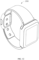
FIG. 12 is a schematic structural diagram of an electronic apparatus according to an embodiment of this application. -
Batteries 100, 100a, 100b, 100c, 100d, 100e, 100f, 100g, 100h, and 100i Housing 10 Insulation member 20 First active substance layers 30, 513, and 553 Second active substance layers 40, 533, and 533a First wall body 11 Second wall body 13 Third wall body 15 Accommodating cavity 101 Surfaces 110 and 150 Insulation element 17 First electrode plates 51, 51a, and 51b Second electrode plates 53, 53a, and 53b First conductive members 61, 61a, and 61b Insulation materials 612, 632, 612a, and 632a First current collectors 511, 511a, and 511b Second current collectors 531, 531a, and 531b Second conductive members 63, 63a, 63b, and 63c Third electrode plate 55 Third current collector 551 Electronic apparatus 200 - This application is further described in the following specific embodiments with reference to the accompanying drawings.
- The following clearly and completely describes the technical solutions in the embodiments of this application with reference to the accompanying drawings in the embodiments of this application. Apparently, the described embodiments are merely some but not all of the embodiments of this application.
- Unless otherwise defined, all technical and scientific terms used herein shall have the same meanings as those commonly understood by a person skilled in the art to which this application pertains. The terms used herein in this specification of this application are only used to describe specific embodiments, but are not intended to limit this application.
- The following describes in detail some embodiments of this application with reference to the accompanying drawings. In absence of conflicts, the following embodiments and features in the embodiments may be combined.
- Referring to
FIG. 1 and FIG. 2 , in an embodiment of this application, abattery 100 includes ahousing 10, aninsulation member 20, a firstactive substance layer 30, and a secondactive substance layer 40. Thebattery 100 may be, but is not limited to, a button cell. - The
housing 10 includes afirst wall body 11, asecond wall body 13, and athird wall body 15. Thefirst wall body 11 is conductive, and thethird wall body 15 and thefirst wall body 11 are opposite each other and spaced apart. Thesecond wall body 13 is connected to thefirst wall body 11 and thethird wall body 15 to enclose a sealedaccommodating cavity 101 in conjunction with thefirst wall body 11 and thethird wall body 15. - In an embodiment, the conductive
first wall body 11 may include a material with a conductive property. In an embodiment, thefirst wall body 11 may include a metal material. In an embodiment, thefirst wall body 11 may include a conductive polymer. - The
insulation member 20, the firstactive substance layer 30, and the secondactive substance layer 40 are accommodated in theaccommodating cavity 101. The secondactive substance layer 40 is disposed on asurface 110 of thefirst wall body 11 that faces thethird wall body 15. The firstactive substance layer 30 and the secondactive substance layer 40 have opposite polarities, and the firstactive substance layer 30 is disposed between thethird wall body 15 and the secondactive substance layer 40 that is disposed on thesurface 110 of thefirst wall body 11. Theinsulation member 20 is disposed between the firstactive substance layer 30 and the secondactive substance layer 40. - In an embodiment, a material of the
insulation member 20 includes at least one of a polymer material with ion conductivity, a lithium-ion compound, an oxide, and a hydroxide. - The polymer material may be, but is not limited to, one or more of polyvinylidene fluoride-hexafluoropropene (PVDF-HFP), polyvinylidene fluoride (PVDF), polyacrylonitrile (PAN), polymethyl methacrylate (PMMA), polyphenylene oxide (PPO), polypropylene carbonate (PPC), polyethylene oxide (PEO), and a derivative of the preceding substances.
- The lithium-ion compound may be selected from, but is not limited to, at least one of lithium phosphate (Li3PO4), lithium titanium phosphate (LixTiy(PO4)3, where 0<x<2 and 0<y<3), lithium aluminum titanium phosphate (LixAlyTiz(PO4)3, where 0<x<2, 0<y<1, and 0<z<3), Li1+x+y(Al, Ga)x(Ti, Ge)2-xSiyP3-yO12 (0≤x≤1 and 0≤y≤1), lithium lanthanum titanate (LixLayTiO3, where 0<x<2 and 0<y<3), lithium germanium thiophosphate (LixGeyPzSw, where 0<x<4, 0<y<1, 0<z<1, and 0<w<5), lithium nitride (LixNy, where 0<x<4 and 0<y<2), SiS2 glass (LixSiySz, where 0≤x<3, 0<y<2, and 0<z<4), P2S5 glass (LixPySz, where 0≤x<3, 0<y<3, and 0<z<7), Li2O, LiF, LiOH, Li2CO3, LiAlO2, Li2O-A12O3-SiO2-P2O5-TiO2-GeO2 ceramics, or garnet ceramics (Li3+xLa3M2O12, where 0≤x≤5, and M is Te, Nb, or Zr).
- The oxide may be selected from, but is not limited to, at least one of HfO2, SrTiO3, SnO2, CeO2, MgO, NiO, CaO, BaO, ZnO, ZrO2, Y2O3, Al2O3, TiO2, SiO2, or the like.
- The hydroxide may be selected from, but is not limited to, at least one of boehmite, magnesium hydroxide, aluminum hydroxide, or the like.
- In an embodiment, the
insulation member 20 may be at least one of a separator, a gel electrolyte, or a solid electrolyte. The gel electrolyte and the solid electrolyte are common types of electrolytes in the battery field and are not limited herein. - The first
active substance layer 30 may be a positive electrode active substance layer or a negative electrode active substance layer. In an embodiment, the firstactive substance layer 30 is a positive electrode active substance layer that includes a positive electrode active material; and the secondactive substance layer 40 is a negative electrode active substance layer that includes a negative electrode active material. In an embodiment, the firstactive substance layer 30 is a negative electrode active substance layer that includes a negative electrode active material; and the secondactive substance layer 40 is a positive electrode active substance layer that includes a positive electrode active material. - The positive electrode active material may include, but is not limited to, one or more of lithium cobalt oxide, lithium nickel cobalt manganate, lithium nickel cobalt aluminate, lithium manganate oxide, lithium manganese iron phosphate, lithium vanadium phosphate, lithium vanadyl phosphate, lithium iron phosphate, lithium titanate, and a lithium-rich manganese-based material.
- The negative electrode active material may include, but is not limited to, one or more of artificial graphite, natural graphite, soft carbon, hard carbon, graphene, carbonaceous mesophase spherule, a silicon-based material, a tin-based material, lithium titanate, or another metal capable of forming an alloy with lithium.
- Referring to
FIG. 12 , the foregoing battery is applied to anelectronic apparatus 200, to supply power to theelectronic apparatus 200. Theelectronic apparatus 200 may be, but is not limited to, a wearable device (such as a watch), a mobile phone, a toy, a drone, and the like. - The following further describes the battery by using embodiments. An example in which the second active substance layer is a negative electrode active substance layer and the first active substance layer is a positive electrode active substance layer is used for description.
- Referring to
FIG. 2 , thethird wall body 15 is a conductive wall body. The firstactive substance layer 30 is disposed on asurface 150 of thethird wall body 15 that faces thefirst wall body 11. Thefirst wall body 11 is insulated from thethird wall body 15. Thethird wall body 15, the firstactive substance layer 30, the secondactive substance layer 40, and thefirst wall body 11 are stacked in a first direction X. The first direction X is a direction in which thethird wall body 15 faces thefirst wall body 11 or a direction in which thefirst wall body 11 faces thethird wall body 15. In some embodiments, the first direction X may be a thickness direction of a battery. - Specifically, in this embodiment, an
insulation element 17 may be provided along a periphery of thethird wall body 15, and theinsulation element 17 is connected to thethird wall body 15 and thesecond wall body 13, to insulate thefirst wall body 11 from thethird wall body 15. In this case, thesecond wall body 13 may be conductive or non-conductive, and thesecond wall body 13 and thefirst wall body 11 may be directly or indirectly connected. For example, thefirst wall body 11 and thesecond wall body 13 may be integrally formed. - In an embodiment, the
insulation element 17 may include an insulation adhesive, and the insulation adhesive is filled between thethird wall body 15 and thesecond wall body 13. - In an embodiment, the
third wall body 15 may include a material with a conductive property. In an embodiment, thethird wall body 15 may include a metal material. In an embodiment, thethird wall body 15 may include a conductive polymer. - A projection of the first
active substance layer 30 in the first direction X onto a plane perpendicular to the first direction X is within a projection of the secondactive substance layer 40 in the first direction X onto a plane perpendicular to the first direction X. - When a
battery 100 is applied to an electronic apparatus, thefirst wall body 11 and thethird wall body 15 are respectively electrically connected to two electrical connection ends (not shown in the figure) of the electronic apparatus, to supply power to the electronic apparatus. - Referring to
FIG. 3a , a difference from Embodiment 1 is that abattery 100a may further include afirst electrode plate 51 and asecond electrode plate 53 that have opposite polarities and that are accommodated in theaccommodating cavity 101. Thefirst electrode plate 51 and the firstactive substance layer 30 have a same polarity, and thefirst electrode plate 51 is disposed between the firstactive substance layer 30 on thesurface 150 of thethird wall body 15 and the secondactive substance layer 40 on thesurface 110 of thefirst wall body 11. Thesecond electrode plate 53 and the firstactive substance layer 30 disposed on thesurface 150 of thethird wall body 15 have opposite polarities, and thesecond electrode plate 53 is disposed between thefirst electrode plate 51 and the firstactive substance layer 30 disposed on thesurface 150 of thethird wall body 15. - The
insulation members 20 are disposed between thefirst electrode plate 51 and the secondactive substance layer 40 disposed on thesurface 110 of thefirst wall body 11, between thefirst electrode plate 51 and thesecond electrode plate 53, and between thesecond electrode plate 53 and the firstactive substance layer 30 disposed on thesurface 150 of thethird wall body 15. In this embodiment, thefirst electrode plate 51 may be enveloped by theinsulation member 20, that is, theinsulation member 20 is also disposed between thefirst electrode plate 51 and thesecond wall body 13. - The
battery 100a further includes a firstconductive member 61, thefirst electrode plate 51 and thethird wall body 15 are electrically connected through the firstconductive member 61, and the firstconductive member 61 is insulated from thesecond electrode plate 53. In this embodiment, the firstconductive member 61 may be insulated from thesecond electrode plate 53 through aninsulation material 612. In some embodiments, the firstconductive member 61 and thesecond electrode plate 53 may be spaced apart to implement insulation. - A morphology of the first
conductive member 61 is not limited, and may be any morphology such as a solid cylinder, a hollow cylinder, or a sheet. In this embodiment, the firstconductive member 61 is a hollow cylinder, and two ends of the firstconductive member 61 that are spaced apart in the first direction X may be penetrated through (as shown inFIG. 3a ) or sealed (as shown inFIG. 3c ). In this embodiment, as shown inFIG. 3b , the firstconductive member 61 may penetrate through thesecond electrode plate 53, and the two ends of the firstconductive member 61 that are spaced apart in the first direction X are respectively electrically connected to thefirst electrode plate 51 and thethird wall body 15. Theinsulation material 612 may sleeve or be applied on the firstconductive member 61, to insulate the firstconductive member 61 from thesecond electrode plate 53. The firstconductive member 61 in a hollow cylinder shape helps reduce overall mass of the battery, thereby helping increase energy density of the battery. The firstconductive member 61 with two ends sealed helps increase a contact area between the first conductive member and a current collector or an external terminal electrically connected to the two ends of the first conductive member, thereby facilitating stability of electrical connection. In some embodiments, theinsulation material 612 may be, but is not limited to, an insulation adhesive tape or an insulation coating. In some embodiments, the insulation coating may include a ceramic material. - The
second wall body 13 is a conductive wall body, thefirst electrode plate 51 is insulated from thesecond wall body 13, and thesecond electrode plate 53 is electrically connected to thesecond wall body 13. In this embodiment, thefirst electrode plate 51 and thesecond wall body 13 are spaced apart to implement insulation, and thesecond electrode plate 53 comes into direct contact with thesecond wall body 13 to implement electrical connection. Thefirst wall body 11 is electrically connected to thesecond electrode plate 53 through thesecond wall body 13. - In an embodiment, the
second wall body 13 may include a material with a conductive property. In an embodiment, thesecond wall body 13 may include a metal material. In an embodiment, thesecond wall body 13 may include a conductive polymer. - Specifically, the
first electrode plate 51 may include a firstcurrent collector 511 and firstactive substance layers 513 disposed on a surface of the firstcurrent collector 511 that faces thefirst wall body 11 and on a surface of the firstcurrent collector 511 that faces thethird wall body 15. Thesecond electrode plate 53 may include a secondcurrent collector 531 and secondactive substance layers 533 disposed on a surface of the secondcurrent collector 531 that faces thefirst wall body 11 and on a surface of the secondcurrent collector 531 that faces thethird wall body 15. - A projection of the first
active substance layer 513 in a first direction X onto a plane perpendicular to the first direction X is within a projection of the secondactive substance layer 533 in the first direction X onto a plane perpendicular to the first direction X, and is within a projection of the secondactive substance layer 40 in the first direction X onto a plane perpendicular to the first direction X. - When the
battery 100a is applied to an electronic apparatus, one electrical connection terminal of the electronic apparatus is electrically connected to thefirst wall body 11 or thesecond wall body 13, and the other electrical connection terminal is electrically connected to thethird wall body 15, so that thebattery 100a supplies power to the electronic apparatus. - Referring to
FIG. 4 , a difference from Embodiment 2 is that thesecond wall body 13 may be non-conductive. Abattery 100b further includes a secondconductive member 63, thefirst wall body 11 and thesecond electrode plate 53 are electrically connected through the secondconductive member 63, and the secondconductive member 63 is respectively insulated from thefirst electrode plate 51 and athird wall body 15. In this embodiment, insulation between the secondconductive member 63 and thefirst electrode plate 51 and between the secondconductive member 63 and thethird wall body 15 may be implemented through aninsulation material 632. A morphology of the secondconductive member 63 may be the same as or different from that of the firstconductive member 61. For example, in this embodiment, the secondconductive member 63 is a hollow cylinder, and two ends of the secondconductive member 63 that are spaced apart in the first direction X penetrate through. The secondconductive member 63 penetrates through thefirst electrode plate 51, and the two ends of the second conductive member that are spaced apart in the first direction X are respectively electrically connected to the secondcurrent collector 531 and thefirst wall body 11. Theinsulation material 632 may sleeve or be applied on the secondconductive member 63, to insulate the secondconductive member 63 from thefirst electrode plate 51. In some embodiments, theinsulation material 632 may be, but is not limited to, an insulation adhesive tape or an insulation coating. - When the
battery 100b is applied to an electronic apparatus, one electrical connection terminal of the electronic apparatus is electrically connected to thefirst wall body 11, and the other electrical connection terminal is electrically connected to thethird wall body 15, so that thebattery 100b supplies power to the electronic apparatus. - Referring to
FIG. 5a andFIG. 5b , thethird wall body 15 is a conductive wall body. The secondactive substance layer 40 is further disposed on thesurface 150 of thethird wall body 15 that faces thefirst wall body 11. The first direction X is a direction in which thethird wall body 15 faces thefirst wall body 11 or a direction in which thefirst wall body 11 faces thethird wall body 15. In some embodiments, the first direction X may be a thickness direction of a battery. - The
battery 100c includes afirst electrode plate 51a accommodated in anaccommodating cavity 101. Thefirst electrode plate 51a is located between the secondactive substance layer 40 disposed on thesurface 110 of thefirst wall body 11 and the secondactive substance layer 40 disposed on thesurface 150 of thethird wall body 15. Thefirst electrode plate 51a includes a firstcurrent collector 511a and the foregoing firstactive substance layer 30, and the firstactive substance layer 30 is disposed on a surface of the firstcurrent collector 511a. Specifically, the firstactive substance layer 30 is disposed on a surface of the firstcurrent collector 511a that faces thefirst wall body 11 and on a surface of the firstcurrent collector 511a that faces thethird wall body 15. -
Insulation members 20 are disposed between thefirst electrode plate 51a and the secondactive substance layer 40 disposed on thesurface 110 of thefirst wall body 11, and between thefirst electrode plate 51a and the secondactive substance layer 40 disposed on thesurface 150 of thethird wall body 15. In this embodiment, thefirst electrode plate 51a may be enveloped by theinsulation member 20. - The
battery 100c further includes a firstconductive member 61a, and thefirst electrode plate 51a is electrically connected to the firstconductive member 61a. The firstconductive member 61a protrudes or is extended from the third wall body 15 (that is, the firstconductive member 61a penetrates through the third wall body 15), and the firstconductive member 61a is insulated from thethird wall body 15. In this embodiment, the firstconductive member 61a may be insulated from thethird wall body 15 through aninsulation material 612a. Specifically, the firstconductive member 61a is a hollow cylinder, and of two ends of the first conductive member that are spaced apart in a first direction X, one end is electrically connected to the firstcurrent collector 511a, and the other end penetrates through thethird wall body 15 and protrudes from thethird wall body 15. Theinsulation material 612a may sleeve or be applied on the firstconductive member 61a, to insulate the firstconductive member 61a from thethird wall body 15. In some embodiments, theinsulation material 612a may be, but is not limited to, an insulation adhesive tape or an insulation coating. - The
second wall body 13 is a conductive wall body, thesecond wall body 13 is separately electrically connected to thefirst wall body 11 and thethird wall body 15, and thesecond wall body 13 is insulated from thefirst electrode plate 51a. In this embodiment, thesecond wall body 13 separately comes into contact with thefirst wall body 11 and thethird wall body 15 to implement the electrical connection. - In an embodiment, the
first wall body 11, thesecond wall body 13, and thethird wall body 15 each may include a material with a conductive property. In an embodiment, thefirst wall body 11, thesecond wall body 13, and thethird wall body 15 each may include a metal material. In an embodiment, thefirst wall body 11, thesecond wall body 13, and thethird wall body 15 each may include a conductive polymer. - A projection of the first
active substance layer 30 disposed on the surface of the firstcurrent collector 511a in the first direction X onto a plane perpendicular to the first direction X is within a projection of the secondactive substance layer 40 disposed on thesurface 110 of thefirst wall body 11 in the first direction X onto a plane perpendicular to the first direction X, and is within a projection of the secondactive substance layer 40 disposed on thesurface 150 of thethird wall body 15 in the first direction X onto a plane perpendicular to the first direction X. - When the
battery 100c is applied to an electronic apparatus, one electrical connection terminal of the electronic apparatus is electrically connected to thefirst wall body 11, thesecond wall body 13, or thethird wall body 15, and the other electrical connection terminal is electrically connected to the firstconductive member 61a, so that thebattery 100c supplies power to the electronic apparatus. - Referring to
FIG. 6 , a difference from Embodiment 4 is that an end of a firstconductive member 61 farther away from a firstcurrent collector 511a is extended from thethird wall body 15. Abattery 100d further includes a secondconductive member 63a, afirst wall body 11 and athird wall body 15 are electrically connected through the secondconductive member 63a, and the secondconductive member 63a is insulated from afirst electrode plate 51a. In this embodiment, the secondconductive member 63a may be insulated from thefirst electrode plate 51a through aninsulation material 632a. - Specifically, the second
conductive member 63a is a hollow cylinder and penetrates through thefirst electrode plate 51a, and two ends of the secondconductive member 63a that are spaced apart in a first direction X are respectively electrically connected to thefirst wall body 11 and thethird wall body 15. Theinsulation material 632a may sleeve or be applied on the secondconductive member 63a, to insulate the secondconductive member 63a from thefirst electrode plate 51a. In some embodiments, theinsulation material 632a may be, but is not limited to, an insulation adhesive tape or an insulation coating. - Referring to
FIG. 7 , a difference from Embodiment 4 is that abattery 100e may further include asecond electrode plate 53a that has an opposite polarity to thefirst electrode plate 51a and that is accommodated in theaccommodating cavity 101, and athird electrode plate 55 that has a same polarity as thefirst electrode plate 51a and that is accommodated in theaccommodating cavity 101. - The
second electrode plate 53a is located between thefirst electrode plate 51a and the secondactive substance layer 40 disposed on thesurface 110 of thefirst wall body 11, and thethird electrode plate 55 is located between thesecond electrode plate 53a and the secondactive substance layer 40 disposed on thesurface 110 of thefirst wall body 11. - The
insulation members 20 are located between thefirst electrode plate 51a and the secondactive substance layer 40 disposed on thesurface 150 of thethird wall body 15, between thefirst electrode plate 51a and thesecond electrode plate 53a, between thesecond electrode plate 53a and thethird electrode plate 55, and between thethird electrode plate 55 and the secondactive substance layer 40 disposed on thesurface 110 of thefirst wall body 11. In this embodiment, thethird electrode plate 55 may be enveloped by theinsulation member 20. - Each
second wall body 13 is also electrically connected to thesecond electrode plate 53a, and thesecond wall body 13 is also insulated from thethird electrode plate 55. Thesecond electrode plate 53a includes a secondcurrent collector 531a and a second active substance layer 533a disposed on a surface of the secondcurrent collector 531a. Thethird electrode plate 55 includes a thirdcurrent collector 551 and a firstactive substance layer 553 disposed on a surface of the thirdcurrent collector 551. In this embodiment, thesecond wall body 13 comes into contact with the secondcurrent collector 531a in thesecond electrode plate 53a to implement electrical connection. - The first
conductive member 61a is also electrically connected to thethird electrode plate 55, and the firstconductive member 61a is insulated from thesecond electrode plate 53a. In this embodiment, the firstconductive member 61a may be insulated from thesecond electrode plate 53a through aninsulation material 614. Specifically, the firstconductive member 61a is a hollow cylinder and penetrates through thefirst electrode plate 51a and thesecond electrode plate 53a. Of two ends of the firstconductive member 61a that are spaced apart in the first direction X, one end is electrically connected to the thirdcurrent collector 551, and the other end penetrates through thethird wall body 15 and protrudes from thethird wall body 15. Twoinsulation materials 614 may alternately cover or be applied on the firstconductive member 61a, to insulate the firstconductive member 61a from thesecond electrode plate 53a and insulate the firstconductive member 61a from thethird wall body 15. In some embodiments, theinsulation material 614 may be, but is not limited to, an insulation adhesive tape or an insulation coating. - A projection of the first
active substance layer 30 disposed on the surface of the firstcurrent collector 511a in the first direction X onto a plane perpendicular to the first direction X is also within a projection of the second active substance layer 533a disposed on the surface of the secondcurrent collector 531a in the first direction X onto a plane perpendicular to the first direction X. - A projection of the first
active substance layer 553 disposed on the surface of the thirdcurrent collector 551 in the first direction X onto a plane perpendicular to the first direction X is within a projection of the secondactive substance layer 40 disposed on thesurface 110 of thefirst wall body 11 in the first direction X onto a plane perpendicular to the first direction X, is within a projection of the secondactive substance layer 40 disposed on thesurface 150 of thethird wall body 15 in the first direction X onto a plane perpendicular to the first direction X, and is also within a projection of the second active substance layer 533a disposed on the surface of the secondcurrent collector 531a in the first direction X onto a plane perpendicular to the first direction X. - Referring to
FIG. 8 , a difference from Embodiment 6 is that thesecond wall body 13 may be non-conductive. Abattery 100f further includes a secondconductive member 63b, thefirst wall body 11, thesecond electrode plate 53a, and thethird wall body 15 are electrically connected through the secondconductive member 63b, and the secondconductive member 63b is separately insulated from thefirst electrode plate 51a and thethird electrode plate 55. Specifically, the secondconductive member 63b is a hollow cylinder and penetrates through thefirst electrode plate 51a, thesecond electrode plate 53a, and thethird electrode plate 55. Two ends of the secondconductive member 63b that are spaced apart in the first direction X are respectively electrically connected to thefirst wall body 11 and thethird wall body 15. Two insulation materials (not marked in the figure) may alternately cover or be applied on the secondconductive member 63b, to insulate the secondconductive member 63b from thefirst electrode plate 51a and insulate the secondconductive member 63b from thethird electrode plate 55. In some embodiments, the insulation material may be, but is not limited to, an insulation adhesive tape or an insulation coating. - When the
battery 100f is applied to an electronic apparatus, one electrical connection terminal of the electronic apparatus is electrically connected to thefirst wall body 11 or thethird wall body 15, and the other electrical connection terminal is electrically connected to the firstconductive member 61a, so that thebattery 100f supplies power to the electronic apparatus. - Referring to
FIG. 9 , abattery 100g includes afirst electrode plate 51b accommodated in anaccommodating cavity 101. Thefirst electrode plate 51b is located between the secondactive substance layer 40 disposed on thesurface 110 of thefirst wall body 11 and thethird wall body 15, and thefirst electrode plate 51b is separated from thethird wall body 15. In this embodiment, thefirst electrode plate 51b is separated from thesecond wall body 13. In this case, thesecond wall body 13 and thethird wall body 15 may be separately conductive or non-conductive, and thesecond wall body 13 may be separately directly or indirectly connected to thefirst wall body 11 and thethird wall body 15. The first direction X is a direction in which thethird wall body 15 faces thefirst wall body 11 or a direction in which thefirst wall body 11 faces thethird wall body 15. In some embodiments, the first direction X may be a thickness direction of the battery. - The
first electrode plate 51b includes a firstcurrent collector 511b and the foregoing firstactive substance layer 30, and the firstactive substance layer 30 is disposed on a surface of the firstcurrent collector 511b that faces thefirst wall body 11. - The
insulation member 20 is disposed between thefirst electrode plate 51b and the secondactive substance layer 40 disposed on thesurface 110 of thefirst wall body 11. In this embodiment, theinsulation member 20 may also be disposed between thefirst electrode plate 51b and thethird wall body 15. Theinsulation member 20 may also be disposed between thefirst electrode plate 51b and thesecond wall body 13. - The
battery 100g further includes a firstconductive member 61b, and thefirst electrode plate 51b is electrically connected to the firstconductive member 61b. The firstconductive member 61b protrudes or is extended from thethird wall body 15, and the firstconductive member 61b is insulated from thethird wall body 15. Specifically, the firstconductive member 61b is a hollow cylinder, and of two ends of the first conductive member that are spaced apart in the first direction X, one end is electrically connected to the firstcurrent collector 511b, and the other end penetrates through thethird wall body 15 and protrudes from thethird wall body 15. The insulation material (not marked in the figure) may sleeve or be applied on the firstconductive member 61b, to insulate the firstconductive member 61b from thethird wall body 15. In some embodiments, the insulation material may be, but is not limited to, an insulation adhesive tape or an insulation coating. - A projection of the first
active substance layer 30 disposed on the surface of the firstcurrent collector 511b in the first direction X onto a plane perpendicular to the first direction X is within a projection of the secondactive substance layer 40 disposed on thesurface 110 of thefirst wall body 11 in the first direction X onto a plane perpendicular to the first direction X. - When the
battery 100g is applied to an electronic apparatus, one electrical connection terminal of the electronic apparatus is electrically connected to thefirst wall body 11, and the other electrical connection terminal is electrically connected to the firstconductive member 61b, so that thebattery 100g supplies power to the electronic apparatus. - Referring to
FIG. 10 , a difference from Embodiment 8 is that abattery 100h further includes asecond electrode plate 53b that has an opposite polarity to afirst electrode plate 51b and that is accommodated in anaccommodating cavity 101. Thesecond electrode plate 53b is disposed between thefirst electrode plate 51b and thethird wall body 15, and thesecond electrode plate 53b is separated from thethird wall body 15. - The first
active substance layer 30 is further disposed on a surface of the firstcurrent collector 511b that faces thesecond electrode plate 53b. Thesecond electrode plate 53b includes a secondcurrent collector 531b and a secondactive substance layer 40 disposed on a surface of the secondcurrent collector 531b that faces thefirst electrode plate 51b. - The
insulation member 20 is further disposed between thefirst electrode plate 51b and thesecond electrode plate 53b. The firstconductive member 61b is further insulated from thesecond electrode plate 53b. - The
second wall body 13 is a conductive wall body, and is respectively electrically connected to thefirst wall body 11 and the secondcurrent collector 531b of thesecond electrode plate 53b. Thesecond wall body 13 is insulated from thefirst electrode plate 51b. In this embodiment, thesecond wall body 13 respectively comes into direct contact with thefirst wall body 11 and the secondcurrent collector 531b of thesecond electrode plate 53b. The firstconductive member 61b is further insulated from thesecond electrode plate 53b. Specifically, the firstconductive member 61b is a hollow cylinder and penetrates through thesecond electrode plate 53b. The insulation material (not marked in the figure) may sleeve or be applied on the firstconductive member 61b, to insulate the firstconductive member 61b from thesecond electrode plate 53b and insulate the firstconductive member 61b from thethird wall body 15. In some embodiments, the insulation material may be, but is not limited to, an insulation adhesive tape or an insulation coating. - In an embodiment, the
second wall body 13 may include a material with a conductive property. In an embodiment, thesecond wall body 13 may include a metal material. In an embodiment, thesecond wall body 13 may include a conductive polymer. - A projection of the first
active substance layer 30 disposed on the surface of the firstcurrent collector 511b in the first direction X onto a plane perpendicular to the first direction X is also within a projection of the secondactive substance layer 40 disposed on a surface of the secondcurrent collector 531b in the first direction X onto a plane perpendicular to the first direction X. - When the
battery 100h is applied to an electronic apparatus, one electrical connection terminal of the electronic apparatus is electrically connected to thefirst wall body 11 or thesecond wall body 13, and the other electrical connection terminal is electrically connected to the firstconductive member 61b, so that thebattery 100h supplies power to the electronic apparatus. - Referring to
FIG. 11 , a difference from Embodiment 9 is that thesecond wall body 13 may be non-conductive. Abattery 100i further includes a secondconductive member 63c, thefirst wall body 11 and thesecond electrode plate 53b are electrically connected through the secondconductive member 63c, and the secondconductive member 63c is insulated from thefirst electrode plate 51b. Specifically, the secondconductive member 63c is a hollow cylinder and penetrates through thefirst electrode plate 51b, and two ends of the secondconductive member 63c that are spaced apart in the first direction X are respectively electrically connected to thefirst wall body 11 and the secondcurrent collector 531b. The insulation material (not marked in the figure) may sleeve or be applied on the secondconductive member 63c, to insulate the secondconductive member 63c from thefirst electrode plate 51b. In some embodiments, the insulation material may be, but is not limited to, an insulation adhesive tape or an insulation coating. - When the
battery 100i is applied to an electronic apparatus, one electrical connection terminal of the electronic apparatus is electrically connected to thefirst wall body 11, and the other electrical connection terminal is electrically connected to the firstconductive member 61b, so that thebattery 100i supplies power to the electronic apparatus. - It can be understood that, in this application, the number of electrode plates in the
accommodating cavity 101 of the battery can be adjusted as needed, and is not exhaustively listed in this application. - In the battery in this application, because the second
active substance layer 40 is provided on thefirst wall body 11, that is, thefirst wall body 11 serves as a current collector, thehousing 10 and internal space thereof are fully used, thereby helping improve energy density of the battery and making the battery thinner. In addition, the secondactive substance layer 40 or the firstactive substance layer 30 is provided on thethird wall body 15, to further improve the energy density of the battery. - In addition, a person of ordinary skill in the art may make various other corresponding changes and variations based on the technical idea of this application, but all these changes and variations shall fall within the protection scope of the claims of this application.
Claims (16)
- A battery, comprising a housing, wherein the housing comprises a first wall body, a second wall body, and a third wall body, the first wall body is conductive and disposed opposite to the third wall body, and the second wall body is connected to the first wall body and the third wall body to enclose an accommodating cavity in conjunction with the first wall body and the third wall body;
andthe battery further comprises an insulation member, and a first active substance layer and a second active substance layer that have opposite polarities, wherein the insulation member, the first active substance layer, and the second active substance layer are accommodated in the accommodating cavity;the second active substance layer is disposed on a surface of the first wall body that faces the third wall body;the first active substance layer is disposed between the second active substance layer and the third wall body; andthe insulation member is disposed between the first active substance layer and the second active substance layer. - The battery according to claim 1, characterized in that the third wall body is a conductive wall body, the first active substance layer is disposed on a surface of the third wall body that faces the first wall body, and the third wall body is insulated from the first wall body.
- The battery according to claim 2, characterized in that an insulation element is disposed between the third wall body and the second wall body.
- The battery according to claim 2, characterized in that the battery further comprises a first electrode plate and a second electrode plate that are accommodated in the accommodating cavity;the first electrode plate comprises a first current collector and the first active substance layer disposed on a surface of the first current collector, and the second electrode plate comprises a second current collector and the second active substance layer disposed on a surface of the second current collector; andthe first electrode plate is disposed between the first wall body and the third wall body, and the second electrode plate is disposed between the first electrode plate and the third wall body.
- The battery according to claim 4, characterized in that the first current collector is electrically connected to the third wall body through a first conductive member, and the first conductive member is insulated from the second electrode plate; and
the first wall body is electrically connected to the second current collector through a second conductive member, and the second conductive member is insulated from the first electrode plate; or the first wall body is electrically connected to the second current collector through the conductive second wall body, and the second wall body is insulated from the first electrode plate. - The battery according to claim 5, characterized in that the first conductive member penetrates through the second electrode plate in a first direction, and an insulation material is disposed between the first conductive member and the second electrode plate.
- The battery according to claim 5, characterized in that the first conductive member is a hollow cylinder with sealed ends.
- The battery according to claim 5, characterized in that the insulation member is disposed between the first electrode plate and the second wall body.
- The battery according to claim 1, characterized in that the third wall body is a conductive wall body, and the second active substance layer is further disposed on a surface of the third wall body that faces the first wall body; and
the battery further comprises a first electrode plate accommodated in the accommodating cavity, and the first electrode plate comprises a first current collector and the first active substance layer disposed on a surface of the first current collector. - The battery according to claim 9, characterized in that the battery further comprises a first conductive member, the first current collector is electrically connected to the first conductive member, the first conductive member is extended from the third wall body, and the first conductive member is insulated from the third wall body; and
the first wall body is electrically connected to the third wall body through the conductive second wall body, and the second wall body is insulated from the first electrode plate. - The battery according to claim 10, characterized in that the first conductive member penetrates through the third wall body in a first direction, and an insulation material is disposed between the first conductive member and the third wall body.
- The battery according to claim 10, characterized in that the battery further comprises a second electrode plate and a third electrode plate that are accommodated in the accommodating cavity;the second electrode plate comprises a second current collector and the second active substance layer disposed on a surface of the second current collector, and the third electrode plate comprises a third current collector and the first active substance layer disposed on a surface of the third current collector;the second electrode plate is disposed between the first electrode plate and the first wall body, and the third electrode plate is disposed between the second electrode plate and the first wall body; andthe first conductive member is electrically connected to the third current collector and insulated from the second electrode plate, and the second wall body is electrically connected to the second current collector and insulated from the third electrode plate.
- The battery according to claim 1, characterized in that the battery further comprises a first electrode plate accommodated in the accommodating cavity, wherein the first electrode plate comprises a first current collector and the first active substance layer disposed on a surface of the first current collector; and
the first electrode plate is separated from the third wall body, the first current collector is electrically connected to the first conductive member, the first conductive member is extended from the third wall body, and the first conductive member is insulated from the third wall body. - The battery according to claim 13, characterized in that the battery further comprises a second electrode plate accommodated in the accommodating cavity, the second electrode plate comprises a second current collector and the second active substance layer disposed on a surface of the second current collector, the second electrode plate is disposed between the first electrode plate and the third wall body, the second electrode plate is separated from the third wall body, and the first conductive member is insulated from the second electrode plate; and
the second current collector is electrically connected to the first wall body through a second conductive member, and the second conductive member is insulated from the first electrode plate; or the second current collector is electrically connected to the first wall body through the conductive second wall body, and the second wall body is insulated from the first electrode plate. - The battery according to claim 1, characterized in that the insulation member comprises at least one of a separator, a gel electrolyte, or a solid electrolyte.
- An electronic apparatus, characterized in that the electronic apparatus comprises the battery according to any one of claims 1 to 15.
Applications Claiming Priority (1)
| Application Number | Priority Date | Filing Date | Title |
|---|---|---|---|
| PCT/CN2021/084157 WO2022205011A1 (en) | 2021-03-30 | 2021-03-30 | Battery and electronic device applying same |
Publications (2)
| Publication Number | Publication Date |
|---|---|
| EP4318721A1 true EP4318721A1 (en) | 2024-02-07 |
| EP4318721A4 EP4318721A4 (en) | 2025-03-26 |
Family
ID=78877411
Family Applications (1)
| Application Number | Title | Priority Date | Filing Date |
|---|---|---|---|
| EP21933691.4A Pending EP4318721A4 (en) | 2021-03-30 | 2021-03-30 | Battery and electronic device applying same |
Country Status (4)
| Country | Link |
|---|---|
| US (1) | US20240030563A1 (en) |
| EP (1) | EP4318721A4 (en) |
| CN (1) | CN113795955B (en) |
| WO (1) | WO2022205011A1 (en) |
Families Citing this family (1)
| Publication number | Priority date | Publication date | Assignee | Title |
|---|---|---|---|---|
| US12620592B2 (en) | 2018-03-05 | 2026-05-05 | The Research Foundation For The State University Of New York | ϵ-VOPO4 cathode production, and applications thereof |
Family Cites Families (19)
| Publication number | Priority date | Publication date | Assignee | Title |
|---|---|---|---|---|
| US7776468B2 (en) * | 2004-03-18 | 2010-08-17 | The Gillette Company | Wafer alkaline cell |
| JP4761725B2 (en) * | 2004-04-27 | 2011-08-31 | 三洋電機株式会社 | Method for producing non-aqueous electrolyte battery |
| WO2007034799A1 (en) * | 2005-09-21 | 2007-03-29 | Matsushita Electric Industrial Co., Ltd. | Flat organic electrolyte battery |
| US7858230B2 (en) * | 2005-10-26 | 2010-12-28 | The Gillette Company | Battery cathodes |
| JP5504708B2 (en) * | 2009-06-25 | 2014-05-28 | 日産自動車株式会社 | Bipolar secondary battery |
| US20140087239A1 (en) * | 2012-09-27 | 2014-03-27 | Medtronic, Inc. | Hermetic coin cell-type assemblies |
| CN204441383U (en) * | 2015-02-27 | 2015-07-01 | 山东润昇电源科技有限公司 | The button-shaped LiFePO4 chargeable lithium cell of a kind of high power capacity |
| US10340528B2 (en) * | 2015-12-02 | 2019-07-02 | California Institute Of Technology | Three-dimensional ion transport networks and current collectors for electrochemical cells |
| WO2018090177A1 (en) * | 2016-11-15 | 2018-05-24 | 宁德时代新能源科技股份有限公司 | Secondary battery and battery module |
| CN107342395A (en) * | 2017-08-06 | 2017-11-10 | 朱程显 | Lithium coin cells with multilayer steel loop or steel mesh |
| WO2019050356A1 (en) * | 2017-09-11 | 2019-03-14 | 주식회사 유뱃 | Electrochemical element and manufacturing method therefor |
| JP7139923B2 (en) * | 2018-06-26 | 2022-09-21 | トヨタ自動車株式会社 | ALL-SOLID BATTERY, RESIN COATING APPARATUS, AND METHOD FOR MANUFACTURING ALL-SOLID BATTERY |
| CN111244388B (en) * | 2018-07-13 | 2022-02-25 | 宁德时代新能源科技股份有限公司 | Pole piece, manufacturing method of pole piece, and secondary battery |
| JP7047667B2 (en) * | 2018-08-24 | 2022-04-05 | トヨタ自動車株式会社 | All solid state battery |
| CN109830732B (en) * | 2019-01-25 | 2024-08-13 | 哈尔滨工业大学(深圳) | A stack structure of an asymmetric flat-plate high-temperature solid-state fuel cell |
| CN112242499A (en) * | 2019-07-19 | 2021-01-19 | 宁德新能源科技有限公司 | Cell and battery with said cell |
| CN211828840U (en) * | 2020-03-20 | 2020-10-30 | 惠州市禾腾能源科技有限公司 | Tabletting type lithium ion battery pole piece |
| CN211879509U (en) * | 2020-04-02 | 2020-11-06 | 宁德新能源科技有限公司 | Electrode pole piece, electrochemical device and electronic device comprising same |
| CN112331927B (en) * | 2020-11-10 | 2022-05-20 | 珠海冠宇电池股份有限公司 | Battery lamination electricity core and battery |
-
2021
- 2021-03-30 WO PCT/CN2021/084157 patent/WO2022205011A1/en not_active Ceased
- 2021-03-30 CN CN202180003188.3A patent/CN113795955B/en active Active
- 2021-03-30 EP EP21933691.4A patent/EP4318721A4/en active Pending
-
2023
- 2023-09-29 US US18/374,698 patent/US20240030563A1/en active Pending
Also Published As
| Publication number | Publication date |
|---|---|
| US20240030563A1 (en) | 2024-01-25 |
| EP4318721A4 (en) | 2025-03-26 |
| WO2022205011A1 (en) | 2022-10-06 |
| CN113795955A (en) | 2021-12-14 |
| CN113795955B (en) | 2024-10-22 |
Similar Documents
| Publication | Publication Date | Title |
|---|---|---|
| KR101577881B1 (en) | Bipolar all-solid-state battery | |
| JP4437890B2 (en) | Solar cell composite thin film solid lithium ion secondary battery | |
| TWI793480B (en) | Longitudinal constraints for energy storage devices | |
| KR101273722B1 (en) | Anode and Battery | |
| US20110223487A1 (en) | Electrochemical cell with sintered cathode and both solid and liquid electrolyte | |
| JP2008078119A (en) | Totally solid storage element | |
| WO2015126074A1 (en) | Battery cell including hole | |
| ATE242918T1 (en) | BIPOLAR ELECTROCHEMICAL BATTERY MADE OF STACKED PLATE CELLS | |
| KR102645090B1 (en) | Unit cell, and preparation method thereof | |
| CN209312927U (en) | Electrode assembly with improved thermal stability | |
| CN112602211B (en) | Water-based hybrid lithium ion capacitor battery with water-in-salt electrolyte | |
| JP2000331684A (en) | Stacked solid secondary battery | |
| US20240030563A1 (en) | Battery and electronic apparatus using such battery | |
| KR20180032530A (en) | Batteries, battery packs, electronic devices, electric vehicles, power storage devices, and power systems | |
| CN101154750A (en) | High power gel polymer lithium ion power cell and method of producing the same | |
| US20230125965A1 (en) | Partition plate and electrochemical apparatus and electronic apparatus including such partition plate | |
| WO2011064862A1 (en) | Solid state battery module | |
| JP2020119758A (en) | Positive electrode material, manufacturing method thereof, battery, and electronic device | |
| KR20240085575A (en) | All solid state baterry | |
| CN108550774A (en) | A kind of hole connection structure of combination stratiform solid-state thin-film battery group | |
| JP2001143763A (en) | Flat non-aqueous electrolyte secondary battery | |
| JP2022129560A (en) | Stacked solid-state battery | |
| JP2022111714A (en) | Stacked solid-state battery | |
| Nathan et al. | Recent advances in three dimensional thin film microbatteries | |
| JP7786590B2 (en) | Negative electrode and secondary battery |
Legal Events
| Date | Code | Title | Description |
|---|---|---|---|
| STAA | Information on the status of an ep patent application or granted ep patent |
Free format text: STATUS: THE INTERNATIONAL PUBLICATION HAS BEEN MADE |
|
| PUAI | Public reference made under article 153(3) epc to a published international application that has entered the european phase |
Free format text: ORIGINAL CODE: 0009012 |
|
| STAA | Information on the status of an ep patent application or granted ep patent |
Free format text: STATUS: REQUEST FOR EXAMINATION WAS MADE |
|
| 17P | Request for examination filed |
Effective date: 20231030 |
|
| AK | Designated contracting states |
Kind code of ref document: A1 Designated state(s): AL AT BE BG CH CY CZ DE DK EE ES FI FR GB GR HR HU IE IS IT LI LT LU LV MC MK MT NL NO PL PT RO RS SE SI SK SM TR |
|
| DAV | Request for validation of the european patent (deleted) | ||
| DAX | Request for extension of the european patent (deleted) | ||
| A4 | Supplementary search report drawn up and despatched |
Effective date: 20250224 |
|
| RIC1 | Information provided on ipc code assigned before grant |
Ipc: H01M 10/0585 20100101AFI20250218BHEP |