EP4318113A1 - Light control sheet, light control device, photosensitive composition, and method for manufacturing light control sheet - Google Patents
Light control sheet, light control device, photosensitive composition, and method for manufacturing light control sheet Download PDFInfo
- Publication number
- EP4318113A1 EP4318113A1 EP22781279.9A EP22781279A EP4318113A1 EP 4318113 A1 EP4318113 A1 EP 4318113A1 EP 22781279 A EP22781279 A EP 22781279A EP 4318113 A1 EP4318113 A1 EP 4318113A1
- Authority
- EP
- European Patent Office
- Prior art keywords
- light control
- liquid crystal
- acrylate
- control sheet
- alkyl group
- Prior art date
- Legal status (The legal status is an assumption and is not a legal conclusion. Google has not performed a legal analysis and makes no representation as to the accuracy of the status listed.)
- Granted
Links
Images



Classifications
-
- G—PHYSICS
- G02—OPTICS
- G02F—OPTICAL DEVICES OR ARRANGEMENTS FOR THE CONTROL OF LIGHT BY MODIFICATION OF THE OPTICAL PROPERTIES OF THE MEDIA OF THE ELEMENTS INVOLVED THEREIN; NON-LINEAR OPTICS; FREQUENCY-CHANGING OF LIGHT; OPTICAL LOGIC ELEMENTS; OPTICAL ANALOGUE/DIGITAL CONVERTERS
- G02F1/00—Devices or arrangements for the control of the intensity, colour, phase, polarisation or direction of light arriving from an independent light source, e.g. switching, gating or modulating; Non-linear optics
- G02F1/01—Devices or arrangements for the control of the intensity, colour, phase, polarisation or direction of light arriving from an independent light source, e.g. switching, gating or modulating; Non-linear optics for the control of the intensity, phase, polarisation or colour
- G02F1/13—Devices or arrangements for the control of the intensity, colour, phase, polarisation or direction of light arriving from an independent light source, e.g. switching, gating or modulating; Non-linear optics for the control of the intensity, phase, polarisation or colour based on liquid crystals, e.g. single liquid crystal display cells
- G02F1/133—Constructional arrangements; Operation of liquid crystal cells; Circuit arrangements
- G02F1/1333—Constructional arrangements; Manufacturing methods
- G02F1/1337—Surface-induced orientation of the liquid crystal molecules, e.g. by alignment layers
- G02F1/133711—Surface-induced orientation of the liquid crystal molecules, e.g. by alignment layers by organic films, e.g. polymeric films
-
- C—CHEMISTRY; METALLURGY
- C09—DYES; PAINTS; POLISHES; NATURAL RESINS; ADHESIVES; COMPOSITIONS NOT OTHERWISE PROVIDED FOR; APPLICATIONS OF MATERIALS NOT OTHERWISE PROVIDED FOR
- C09K—MATERIALS FOR MISCELLANEOUS APPLICATIONS, NOT PROVIDED FOR ELSEWHERE
- C09K19/00—Liquid crystal materials
- C09K19/52—Liquid crystal materials characterised by components which are not liquid crystals, e.g. additives with special physical aspect: solvents, solid particles
- C09K19/54—Additives having no specific mesophase characterised by their chemical composition
- C09K19/542—Macromolecular compounds
- C09K19/544—Macromolecular compounds as dispersing or encapsulating medium around the liquid crystal
-
- B—PERFORMING OPERATIONS; TRANSPORTING
- B32—LAYERED PRODUCTS
- B32B—LAYERED PRODUCTS, i.e. PRODUCTS BUILT-UP OF STRATA OF FLAT OR NON-FLAT, e.g. CELLULAR OR HONEYCOMB, FORM
- B32B27/00—Layered products comprising a layer of synthetic resin
- B32B27/06—Layered products comprising a layer of synthetic resin as the main or only constituent of a layer, which is next to another layer of the same or of a different material
- B32B27/08—Layered products comprising a layer of synthetic resin as the main or only constituent of a layer, which is next to another layer of the same or of a different material of synthetic resin
-
- B—PERFORMING OPERATIONS; TRANSPORTING
- B32—LAYERED PRODUCTS
- B32B—LAYERED PRODUCTS, i.e. PRODUCTS BUILT-UP OF STRATA OF FLAT OR NON-FLAT, e.g. CELLULAR OR HONEYCOMB, FORM
- B32B27/00—Layered products comprising a layer of synthetic resin
- B32B27/30—Layered products comprising a layer of synthetic resin comprising vinyl (co)polymers; comprising acrylic (co)polymers
- B32B27/308—Layered products comprising a layer of synthetic resin comprising vinyl (co)polymers; comprising acrylic (co)polymers comprising acrylic (co)polymers
-
- C—CHEMISTRY; METALLURGY
- C08—ORGANIC MACROMOLECULAR COMPOUNDS; THEIR PREPARATION OR CHEMICAL WORKING-UP; COMPOSITIONS BASED THEREON
- C08F—MACROMOLECULAR COMPOUNDS OBTAINED BY REACTIONS ONLY INVOLVING CARBON-TO-CARBON UNSATURATED BONDS
- C08F222/00—Copolymers of compounds having one or more unsaturated aliphatic radicals, each having only one carbon-to-carbon double bond, and at least one being terminated by a carboxyl radical and containing at least one other carboxyl radical in the molecule; Salts, anhydrides, esters, amides, imides, or nitriles thereof
- C08F222/10—Esters
- C08F222/1006—Esters of polyhydric alcohols or polyhydric phenols
- C08F222/106—Esters of polycondensation macromers
- C08F222/1065—Esters of polycondensation macromers of alcohol terminated (poly)urethanes, e.g. urethane(meth)acrylates
-
- C—CHEMISTRY; METALLURGY
- C09—DYES; PAINTS; POLISHES; NATURAL RESINS; ADHESIVES; COMPOSITIONS NOT OTHERWISE PROVIDED FOR; APPLICATIONS OF MATERIALS NOT OTHERWISE PROVIDED FOR
- C09K—MATERIALS FOR MISCELLANEOUS APPLICATIONS, NOT PROVIDED FOR ELSEWHERE
- C09K19/00—Liquid crystal materials
- C09K19/02—Liquid crystal materials characterised by optical, electrical or physical properties of the components, in general
-
- C—CHEMISTRY; METALLURGY
- C09—DYES; PAINTS; POLISHES; NATURAL RESINS; ADHESIVES; COMPOSITIONS NOT OTHERWISE PROVIDED FOR; APPLICATIONS OF MATERIALS NOT OTHERWISE PROVIDED FOR
- C09K—MATERIALS FOR MISCELLANEOUS APPLICATIONS, NOT PROVIDED FOR ELSEWHERE
- C09K19/00—Liquid crystal materials
- C09K19/04—Liquid crystal materials characterised by the chemical structure of the liquid crystal components, e.g. by a specific unit
- C09K19/38—Polymers
- C09K19/3833—Polymers with mesogenic groups in the side chain
- C09K19/3838—Polyesters; Polyester derivatives
-
- G—PHYSICS
- G02—OPTICS
- G02F—OPTICAL DEVICES OR ARRANGEMENTS FOR THE CONTROL OF LIGHT BY MODIFICATION OF THE OPTICAL PROPERTIES OF THE MEDIA OF THE ELEMENTS INVOLVED THEREIN; NON-LINEAR OPTICS; FREQUENCY-CHANGING OF LIGHT; OPTICAL LOGIC ELEMENTS; OPTICAL ANALOGUE/DIGITAL CONVERTERS
- G02F1/00—Devices or arrangements for the control of the intensity, colour, phase, polarisation or direction of light arriving from an independent light source, e.g. switching, gating or modulating; Non-linear optics
- G02F1/0009—Materials therefor
- G02F1/0063—Optical properties, e.g. absorption, reflection or birefringence
-
- B—PERFORMING OPERATIONS; TRANSPORTING
- B32—LAYERED PRODUCTS
- B32B—LAYERED PRODUCTS, i.e. PRODUCTS BUILT-UP OF STRATA OF FLAT OR NON-FLAT, e.g. CELLULAR OR HONEYCOMB, FORM
- B32B2270/00—Resin or rubber layer containing a blend of at least two different polymers
-
- B—PERFORMING OPERATIONS; TRANSPORTING
- B32—LAYERED PRODUCTS
- B32B—LAYERED PRODUCTS, i.e. PRODUCTS BUILT-UP OF STRATA OF FLAT OR NON-FLAT, e.g. CELLULAR OR HONEYCOMB, FORM
- B32B2305/00—Condition, form or state of the layers or laminate
- B32B2305/55—Liquid crystals
-
- B—PERFORMING OPERATIONS; TRANSPORTING
- B32—LAYERED PRODUCTS
- B32B—LAYERED PRODUCTS, i.e. PRODUCTS BUILT-UP OF STRATA OF FLAT OR NON-FLAT, e.g. CELLULAR OR HONEYCOMB, FORM
- B32B2307/00—Properties of the layers or laminate
- B32B2307/40—Properties of the layers or laminate having particular optical properties
- B32B2307/41—Opaque
-
- B—PERFORMING OPERATIONS; TRANSPORTING
- B32—LAYERED PRODUCTS
- B32B—LAYERED PRODUCTS, i.e. PRODUCTS BUILT-UP OF STRATA OF FLAT OR NON-FLAT, e.g. CELLULAR OR HONEYCOMB, FORM
- B32B2307/00—Properties of the layers or laminate
- B32B2307/40—Properties of the layers or laminate having particular optical properties
- B32B2307/412—Transparent
-
- C—CHEMISTRY; METALLURGY
- C09—DYES; PAINTS; POLISHES; NATURAL RESINS; ADHESIVES; COMPOSITIONS NOT OTHERWISE PROVIDED FOR; APPLICATIONS OF MATERIALS NOT OTHERWISE PROVIDED FOR
- C09K—MATERIALS FOR MISCELLANEOUS APPLICATIONS, NOT PROVIDED FOR ELSEWHERE
- C09K2219/00—Aspects relating to the form of the liquid crystal [LC] material, or by the technical area in which LC material are used
- C09K2219/03—Aspects relating to the form of the liquid crystal [LC] material, or by the technical area in which LC material are used in the form of films, e.g. films after polymerisation of LC precursor
-
- G—PHYSICS
- G02—OPTICS
- G02F—OPTICAL DEVICES OR ARRANGEMENTS FOR THE CONTROL OF LIGHT BY MODIFICATION OF THE OPTICAL PROPERTIES OF THE MEDIA OF THE ELEMENTS INVOLVED THEREIN; NON-LINEAR OPTICS; FREQUENCY-CHANGING OF LIGHT; OPTICAL LOGIC ELEMENTS; OPTICAL ANALOGUE/DIGITAL CONVERTERS
- G02F1/00—Devices or arrangements for the control of the intensity, colour, phase, polarisation or direction of light arriving from an independent light source, e.g. switching, gating or modulating; Non-linear optics
- G02F1/01—Devices or arrangements for the control of the intensity, colour, phase, polarisation or direction of light arriving from an independent light source, e.g. switching, gating or modulating; Non-linear optics for the control of the intensity, phase, polarisation or colour
- G02F1/13—Devices or arrangements for the control of the intensity, colour, phase, polarisation or direction of light arriving from an independent light source, e.g. switching, gating or modulating; Non-linear optics for the control of the intensity, phase, polarisation or colour based on liquid crystals, e.g. single liquid crystal display cells
- G02F1/133—Constructional arrangements; Operation of liquid crystal cells; Circuit arrangements
- G02F1/1333—Constructional arrangements; Manufacturing methods
- G02F1/1334—Constructional arrangements; Manufacturing methods based on polymer dispersed liquid crystals, e.g. microencapsulated liquid crystals
Definitions
- the present disclosure relates to a light control sheet, a light control device, a photosensitive composition, and a method for producing the light control sheet.
- a light control sheet includes a light control layer containing a resin composition and a liquid crystal composition, and a pair of transparent electrode layers that sandwich the light control layer (see, for example, PTL 1).
- a light control device includes the above light control sheet, and a driving unit that applies a drive voltage to the transparent electrode layers. The orientation state of liquid crystal molecules changes depending on the potential difference between the two transparent electrode layers, whereby the light transmittance of the light control sheet changes.
- the light control sheet may be attached to, for example, building materials, such as glass windows and glass walls, automobile glass windows, or the like. Therefore, the light control sheet is exposed to harsh temperature environments. However, in a conventional light control sheet, the viscosity of the light control layer becomes too high or too low due to temperature changes. As a result, even when the driving unit applies a drive voltage, the light control sheet may not have the required haze.
- a light control sheet for achieving the above object is a liquid crystal-dispersed light control sheet comprising: a light control layer containing a resin composition that partitions voids, and a liquid crystal composition filled in the voids; a pair of transparent electrode layers that sandwich the light control layer; and a pair of transparent support layers that sandwich the pair of transparent electrode layers, the liquid crystal composition being composed of a liquid crystal compound having a nematic-isotropic phase transition temperature of 110°C or greater and 140°C or less, the resin composition comprising an acrylic polymer containing a repeating structure represented by the following general formula (1), wherein R 1 is a saturated alkyl group having 1 or more and 12 or fewer carbon atoms, and the resin composition comprising, in the acrylic polymer, a moiety in which the saturated alkyl group is a linear alkyl group.
- a light control device for achieving the above object comprises: the light control sheet; and a control unit that controls application of a drive voltage to the transparent electrode layers.
- the resin composition that partitions voids filled with a liquid crystal composition contains a repeating structure represented by the general formula (1). Therefore, acrylate is polymerized to form a resin composition, compatibility between a liquid crystal compound having a nematic-isotropic phase transition temperature of 110°C or greater and 140°C or less and the acrylate can be obtained. Then, the acrylate polymer and the liquid crystal compound can be phase-separated throughout the entire resin composition. As a result, the light control sheet can operate normally over a wider temperature range.
- the resin composition may contain a bicycloalkyl group as the saturated alkyl group. Further, in the light control sheet, the bicycloalkyl group may contain an isobornyl group.
- the acrylate contains a bicycloalkyl group that is bulkier than a linear alkyl group. Therefore, phase separation between the acrylate polymer and the liquid crystal compound is promoted, while ensuring compatibility between the acrylate and the liquid crystal composition.
- the haze in an opaque state may be 85% or more and the haze in a transparent state may be 6.0 or less at a temperature of -30°C or greater and 100°C or less.
- the light control sheet can operate normally over a wider temperature range.
- the content of the liquid crystal compound contained in the light control layer may be 50 wt%.
- the content of the liquid crystal compound contained in the light control layer is sufficient, and the light control sheet can operate normally even at low or high temperatures.
- a photosensitive composition for achieving the above object is a photosensitive composition for producing a liquid crystal-dispersed light control layer, the photosensitive composition comprising: an acrylate mixture and a liquid crystal composition, the liquid crystal composition being composed of a liquid crystal compound having a nematic-isotropic phase transition temperature of 110°C or greater and 140°C or less, the acrylate mixture comprising pentaerythritol triacrylate, urethane acrylate, and an acrylate represented by the following general formula (2), [Chemical Formula 2] CH 2 CHCOO-R 2 ...
- R 2 is a saturated alkyl group having 1 or more and 12 or fewer carbon atoms
- the acrylate mixture comprising an acrylate in which the saturated alkyl group is a linear alkyl group and an acrylate in which the saturated alkyl group is a bicycloalkyl group.
- a method for producing a light control sheet for achieving the above object is a method for producing a liquid crystal-dispersed light control sheet, the method comprising: a step of applying a photosensitive composition comprising an acrylate mixture and a liquid crystal composition to a transparent support layer of a laminate comprising a transparent electrode layer and the transparent support layer; and a step of applying light of a specific wavelength to the laminate coated with the photosensitive composition and another laminate that are superimposed so that the photosensitive composition is located between the laminates to cure the acrylate mixture, the liquid crystal composition being composed of a liquid crystal compound having a nematic-isotropic phase transition temperature of 110°C or greater and 140°C or less, the acrylate mixture comprising pentaerythritol triacrylate, urethane acrylate, and an acrylate represented by the following general formula (2), [Chemical Formula 3] CH 2 CHCOO-R 2 ...
- R 2 is a saturated alkyl group having 1 or more and 12 or fewer carbon atoms
- the acrylate mixture comprising an acrylate in which the saturated alkyl group is a linear alkyl group and an acrylate in which the saturated alkyl group is a bicycloalkyl group.
- the light control device can operate normally over a wider temperature range.
- FIG. 1 the basic structures of the light control sheet and light control device will be described.
- the light control device 100 includes a light control sheet 10, and a control unit 20 that controls application of a drive voltage to the light control sheet 10.
- the light control sheet 10 may have a structure of a normal-type light control sheet 10N, or a structure of a reverse-type light control sheet 10R.
- Fig. 1 shows a cross-sectional structure of a normal-type light control sheet 10N. The configuration common to the normal-type light control sheet 10N and the reverse-type light control sheet 10R will be described as the configuration of the light control sheet 10.
- the normal-type light control sheet 10N includes a light control layer 11, a first transparent electrode layer 12A, a second transparent electrode layer 12B, a first transparent support layer 13A, and a second transparent support layer 13B.
- the first transparent electrode layer 12A and the second transparent electrode layer 12B sandwich the light control layer 11.
- the first transparent support layer 13A and the second transparent support layer 13B sandwich the light control layer 11, and also sandwich the two transparent electrode layers 12A and 12B.
- the first transparent support layer 13A supports the first transparent electrode layer 12A.
- the second transparent support layer 13B supports the second transparent electrode layer 12B.
- One corner of the surface of the light control sheet 10N is a region where the first transparent electrode layer 12A is exposed.
- a first terminal unit 15A is connected to this region.
- the first terminal unit 15A is connected to the control unit 20 through a wire.
- another corner of the surface of the light control sheet 10N is a region where the second transparent electrode layer 12B is exposed.
- a second terminal unit 15B is connected to this region.
- the second terminal unit 15B is connected to the control unit 20 through a wire.
- the first terminal unit 15A and the second terminal unit 15B constitute the light control sheet 10N.
- the control unit 20 generates a drive voltage, which is an AC voltage, and applies the drive voltage between the first transparent electrode layer 12A and the second transparent electrode layer 12B.
- the light control sheet 10 includes a liquid crystal-dispersed light control layer 11.
- the light control layer 11 contains a resin composition and a liquid crystal composition.
- An example of the light control layer 11 is a polymer dispersed liquid crystal (PDLC).
- PDLC polymer dispersed liquid crystal
- domains which are a plurality of voids, are dispersed in a resin composition containing a polymer compound.
- the liquid crystal composition containing the liquid crystal compound fills the domains.
- the light control layer 11 may be a polymer network liquid crystal (PNLC), a nematic curvilinear aligned phase (NCAP), or a combined structure thereof.
- PNLC polymer network liquid crystal
- NCAP nematic curvilinear aligned phase
- the polymer network liquid crystal has a three-dimensional mesh polymer network, and holds a liquid crystal compound, which is an example of oriented particles, in voids in the polymer network.
- the nematic curvilinear aligned phase holds an encapsulated liquid crystal composition in a resin composition.
- Each of the first transparent electrode layer 12A and the second transparent electrode layer 12B is a conductive transparent layer.
- the material constituting the transparent electrode layers 12A and 12B may be, for example, a polymer containing indium tin oxide (ITO), fluorine-doped tin oxide (FTO), tin oxide, zinc oxide, carbon nanotubes (CNT), or poly(3,4-ethylenedioxythiophene) (PEDOT), or a multilayer film including an Ag alloy thin film.
- ITO indium tin oxide
- FTO fluorine-doped tin oxide
- CNT carbon nanotubes
- PEDOT poly(3,4-ethylenedioxythiophene)
- the transparent support layers 13A and 13B are a transparent substrate.
- the transparent support layers 13A and 13B may be, for example, glass substrates or polymer films composed of one polymer compound selected from the group consisting of polyethylene, polystyrene, polyethylene terephthalate, polyvinyl alcohol, polycarbonate, polyvinyl chloride, polyimide, polysulfone, cycloolefin polymer, and triacetyl cellulose.
- Each of the first terminal unit 15A and the second terminal unit 15B may be composed of, for example, a conductive adhesive layer such as a metal tape, a conductive film, or a conductive paste, and a wire substrate such as FPC, or a wire such as a lead wire.
- a conductive adhesive layer such as a metal tape, a conductive film, or a conductive paste
- a wire substrate such as FPC, or a wire such as a lead wire.
- the light control layer 11 contains a resin composition that partitions voids, and a liquid crystal composition filled in the voids.
- the main component of the liquid crystal composition is a liquid crystal compound.
- the nematic-isotropic phase transition temperature of the liquid crystal compound is 110°C or greater and 140°C or less.
- the liquid crystal compound may be a single compound or a mixture of two or more compounds. When the liquid crystal compound is a mixture, the nematic-isotropic phase transition temperature of all of the compounds constituting the liquid crystal compound may be 110°C or greater and 140°C or less, or the nematic-isotropic phase transition temperature of some of the compounds constituting the liquid crystal compound may be less than 110°C and 140°C or greater.
- the liquid crystal compound is at least one compound selected from the group consisting of those based on phenyl-cyclohexyls, biphenylcyclohexanes, Schiff bases, azo types, azoxy types, biphenyls, terphenyls, benzoic acid esters, tolan types, pyrimidines, pyridazines, cyclohexanecarboxylic acid esters, dicyanobenzenes, naphthalenes, and dioxanes.
- the phenyl-cyclohexane-based liquid crystal compound may be, for example, 4-(4'-n-propylcyclohexyl)-cyanobenzene or 4-(4'-n-pentylcyclohexyl)-cyanobenzene.
- the liquid crystal compound constituting the liquid crystal composition may be a single compound alone or a mixture of several compounds.
- the liquid crystal composition may contain components other than the liquid crystal compound. Examples of such components other than the liquid crystal compound include viscosity-reducing agents, dichroic dyes, defoaming agents, antioxidants, and weathering agents, such as UV absorbers and light stabilizers. Because the liquid crystal compound constituting the liquid crystal composition is a mixture, the nematic-isotropic phase transition temperature of the liquid crystal compound can be easily adjusted.
- the content (wt%) of the liquid crystal compound in the light control layer 11 is the ratio of the weight of the liquid crystal compound to the weight of the light control layer 11.
- the content of the liquid crystal compound in the light control layer 11 may be, for example, 30 wt% or more and 80 wt% or less, and may be 50 wt% or more and 80 wt% or less.
- the content of the liquid crystal compound in the light control layer 11 is preferably 30 wt% or more, and more preferably 50 wt% or more.
- the content of the liquid crystal compound in the light control layer 11 is preferably 80 wt% or less, and more preferably 60 wt% or less.
- the resin composition is a cured product among photosensitive compositions.
- the resin composition is a cured photosensitive compound polymerized by irradiation of light of a specific wavelength, such as ultraviolet light.
- the resin composition includes a repeating structure represented by the following general formula (1).
- the repeating structure represented by the general formula (1) is a structure that repeats repeating units.
- the repeating structure represented by the general formula (1) includes an acrylate-derived repeating unit.
- the bridging group represented by "R 1 " is a saturated alkyl group having 1 or more and 12 or fewer carbon atoms.
- the resin composition contains a repeating structure wherein R 1 is a linear alkyl group.
- the resin composition may further contain a repeating structure wherein R 1 is a bicycloalkyl group.
- the degree of polymerization "n" is 2 or more and 500.
- the resin compound constituting the resin composition may be a homopolymer formed from a single acrylate, a mixture of two or more homopolymers, or a copolymer formed from two or more acrylates.
- the homopolymer has a single repeating structure.
- the copolymer has two or more repeating structures.
- the resin composition may contain a homopolymer having a single repeating structure represented by the general formula (1), or a copolymer having two or more repeating structures represented by the general formula (1).
- the polymer wherein the bridging group R 1 is a linear alkyl group is referred to as the "first acrylic polymer”.
- the first acrylic polymer may be a homopolymer or part of a copolymer.
- the polymer wherein the bridging group R 1 is a cyclic alkyl group is referred to as the "second acrylic polymer”.
- the second acrylic polymer is part of a copolymer.
- the first acrylic polymer is an acrylate polymer.
- the acrylate for forming the first acrylic polymer is at least one photosensitive compound selected from the group consisting of methyl acrylate, ethyl acrylate, propyl acrylate, butyl acrylate, pentyl acrylate, hexyl acrylate, heptyl acrylate, octyl acrylate, nonyl acrylate, decyl acrylate, undecyl acrylate, and dodecyl acrylate.
- the second acrylic polymer is an acrylate polymer.
- the acrylate for forming the second acrylic polymer contains a cycloalkyl group, a bicycloalkyl group, or a tricycloalkyl group.
- the cycloalkyl group-containing acrylate is at least one photosensitive compound selected from the group consisting of cyclopropyl acrylate, cyclobutyl acrylate, cyclopentyl acrylate, cyclohexyl acrylate, cycloheptanyl acrylate, cyclooctyl acrylate, cyclodecanyl acrylate, and cyclododecanyl acrylate.
- the bicycloalkyl group and tricycloalkyl group are polycyclic alkyl groups having a bridged structure in which two carbon atoms that constitute one ring structure are connected with a linear carbon chain.
- the polycyclic alkyl group may be a bicyclic functional group or a tricyclic functional group.
- the bicycloalkyl group may contain an isobornyl group.
- the bicycloalkyl group-containing acrylate is at least one photosensitive compound selected from the group consisting of isobornyl acrylate and bicyclo[3.2.1]octylacrylate.
- the tricycloalkyl group-containing acrylate is at least one photosensitive compound selected from the group consisting of dicyclopentanyl acrylate and tricyclo[5.2.1.0 2,6 ]decane acrylate.
- a liquid crystal compound having a nematic-isotropic phase transition temperature of 110°C or greater and 140°C or less has a structure that is longer in the major axis direction or has more ring structures compared with a liquid crystal compound having a lower transition temperature, and the compatibility between the liquid crystal compound and the acrylates is reduced.
- the compatibility between the liquid crystal compound and the acrylates is reduced, the liquid crystal composition is difficult to disperse uniformly in the photosensitive composition for forming the light control layer 11.
- the size of the voids in the resin composition is preferably 0.3 ⁇ m or more and 3 ⁇ m or less.
- the size of the voids in the resin composition is the diameter of circles circumscribed by the voids in a cross section including the thickness direction of the resin composition.
- the size of the voids in the resin composition is, for example, the average value of the diameters of all voids contained in a cross section having a size of 10 ⁇ m ⁇ 10 ⁇ m.
- the more non-uniformly the liquid crystal composition is dispersed in the photosensitive composition the more non-uniformly the positions of voids in the resin composition are distributed in the plane direction in which the light control layer 11 extends, and the voids tend to have various sizes.
- the acrylates for forming the first acrylic polymer and second acrylic polymer have a low molecular weight and contain a saturated alkyl group, which is a non-polar group, they are highly compatible with the liquid crystal compound, which has a high nematic-isotropic phase transition temperature.
- the content of the first acrylic polymer is 20 wt% or more and 90 wt% or less relative to the total solids content of the photosensitive composition. Further, the content of the first acrylic polymer may be 20 wt% or more and 40 wt% or less.
- the resin composition preferably contains the first acrylic polymer and the second acrylic polymer. In this case, the sum of the content of the first acrylic polymer and the content of the second acrylic polymer is preferably 20 wt% or more and 90 wt% or less relative to the total solid content of the photosensitive composition.
- each of the content of the first acrylic polymer and the content of the second acrylic polymer may be 20 wt% or more and 40 wt% or less relative to the total solid content of the photosensitive composition.
- the bicycloalkyl group has a bulkier structure than the linear alkyl group and the cycloalkyl group, repulsion caused by steric hindrance etc. occurs between the bicycloalkyl group-containing acrylate and the liquid crystal compound.
- nematic-isotropic phase transition temperature nematic phase domains formed by the liquid crystal compound are more likely to occur in the polymer, increasing the degree of phase separation.
- the content of the liquid crystal compound in the photosensitive composition increases; thus, phase separation may be difficult to progress. Because the photosensitive composition contains both an acrylate having a linear alkyl group and an acrylate having a bicycloalkyl group, the compatibility and phase separation can both be improved.
- Fig. 2 shows a cross-sectional structure of the light control sheet 10R.
- the reverse-type light control sheet 10R includes a light control layer 11, transparent electrode layers 12A and 12B, and transparent support layers 13A and 13B, as well as a first orientation layer 14A and a second orientation layer 14B, which are a pair of orientation layers that sandwich the light control layer 11.
- the first orientation layer 14A is located between the light control layer 11 and the first transparent electrode layer 12A.
- the second orientation layer 14B is located between the light control layer 11 and the second transparent electrode layer 12B. That is, the first transparent electrode layer 12A and the second transparent electrode layer 12B sandwich the light control layer 11, and also sandwich the orientation layers 14A and 14B.
- the orientation layers 14A and 14B are vertical orientation films. When the first transparent electrode layer 12A and the second transparent electrode layer 12B are at equipotential, the orientation layers 14A and 14B orient the liquid crystal compound so that the major axis direction of the liquid crystal compound contained in the light control layer 11 is along the normal direction to the plane extending parallel to the orientation layers 14A and 14B. On the other hand, when a potential difference is generated between the transparent electrode layers 12A and 12B, the orientation layers 14A and 14B can change the major axis direction of the liquid crystal compound contained in the light control layer 11 to a direction other than the above normal direction.
- orientation layers 14A and 14B examples include polyesters such as polyamide, polyimide, polycarbonate, polystyrene, polysiloxane, polyethylene terephthalate, and polyethylene naphthalate, and polyacrylates such as polymethyl methacrylate.
- processing to allow the orientation layers 14A and 14B to function as vertical orientation films include rubbing, polarized light irradiation, and microprocessing.
- the direction of the major axis direction of the liquid crystal compound contained in the light control layer 11 is irregular. Therefore, light incident on the light control layer 11 is scattered due to the large refractive index difference between the resin composition and the liquid crystal composition, and the light control sheet 10 becomes opaque.
- the liquid crystal compound is oriented depending on the potential difference, and the major axis direction of the liquid crystal compound becomes parallel to the direction of the electric field between the transparent electrode layers 12A and 12B.
- the applied drive voltage increases within a given range, the transparency of the light control sheet 10 increases.
- the liquid crystal compound is oriented by the orientation layers 14A and 14B, and the major axis direction of the liquid crystal compound is along the normal direction to the plane parallel to the orientation layers 14A and 14B.
- the light control sheet 10 becomes transparent due to the small refractive index difference between the resin composition and the liquid crystal composition.
- the liquid crystal compound is directed in a direction different from the above normal direction depending on the potential difference between the first transparent electrode layer 12A and the second transparent electrode layer 12B.
- the large refractive index difference between the resin composition and the liquid crystal composition light is less likely to pass through the light control layer 11.
- the transparency of the light control sheet 10 decreases.
- the light control sheet 10 is attached to a transparent member located on the boundary between two spaces, and functions as a partition between the two spaces.
- the surface to which the light control sheet 10 is attached may be flat or curved.
- the light control sheet 10 may be attached to building materials, such as glass windows, partitions, and glass walls, or vehicle components, such as automobile glass windows.
- a sheet composed of a first transparent support layer 13A having a first transparent electrode layer 12A on a surface thereof, and a sheet composed of a second transparent support layer 13B having a second transparent electrode layer 12B on a surface thereof are prepared.
- the first transparent electrode layer 12A and the second transparent electrode layer 12B are formed by a known thin film formation method, such as sputtering, vacuum deposition, or coating.
- a photosensitive composition is prepared.
- the photosensitive composition is obtained by mixing and stirring an acrylate represented by the following general formula (2), a liquid crystal composition, a polymerization initiator, and other additives.
- the photosensitive composition may contain pentaerythritol triacrylate or urethane acrylate for the purpose of, for example, enhancing the mechanical strength of the resin composition.
- [Chemical Formula 5] CH 2 CHCOO-R 2 ... (2)
- the bridging group represented by R 2 is a saturated alkyl group having 1 or more and 12 or fewer carbon atoms.
- the acrylates include acrylates wherein R 2 is a linear alkyl group.
- the acrylates may further include at least one selected from the group consisting of acrylates wherein R 2 is a cycloalkyl group, acrylates wherein R 2 is a bicycloalkyl group, and acrylates wherein R 2 is a tricycloalkyl group.
- the acrylates wherein R 2 is a linear alkyl group are at least one selected from the group consisting of methyl acrylate, ethyl acrylate, propyl acrylate, butyl acrylate, pentyl acrylate, hexyl acrylate, heptyl acrylate, octyl acrylate, nonyl acrylate, decyl acrylate, undecyl acrylate, and dodecyl acrylate.
- the acrylates wherein R 2 is a cycloalkyl group are at least one selected from the group consisting of cyclopropyl acrylate, cyclobutyl acrylate, cyclopentyl acrylate, cyclohexyl acrylate, cycloheptanyl acrylate, cyclooctyl acrylate, cyclodecanyl acrylate, and cyclododecanyl acrylate.
- the acrylates wherein R 2 is a bicycloalkyl group are at least one selected from the group consisting of isobornyl acrylate and bicyclo[3.2.1]octylacrylate.
- the acrylates wherein R 2 is a tricycloalkyl group are at least one selected from the group consisting of dicyclopentanyl acrylate and tricyclo[5.2.1.0 2,6 ]decane acrylate.
- a dispersion medium with spacers dispersed therein is applied to at least one of the two sheets, and heated to remove the solvent and disperse the spacers.
- the photosensitive composition is applied to at least one of the two sheets.
- the photosensitive composition is applied by a known coating method, such as an inkjet method, a gravure coating method, a spin coating method, a slit coating method, a bar coating method, a flexo coating method, a die coating method, a dip coating method, or a roll coating method. Then, one sheet is bonded to the other sheet so that the coating layer of the photosensitive composition is located between the two sheets.
- the dispersion of the spacers and the dispersion of the photosensitive composition may be carried out as separate steps, or may be carried out as a single step, for example dispersing a photosensitive composition to which spacers are added.
- the laminate of the layer formed by applying the photosensitive composition and the sheets that sandwich the coating layer is irradiated with light of a specific wavelength.
- the light of a specific wavelength promotes the polymerization reaction of the photosensitive composition.
- the light control layer 11 is thus formed.
- the laminate is formed into a large sheet, for example, by using the roll-to-roll method.
- the laminate is cut out in the desired shape according to the application target of the light control sheet 10N, and a first terminal unit 15A and a second terminal unit 15B are formed for the cut sheet.
- the light control sheet 10N is thus formed.
- Examples 1 to 12 which are examples of the above embodiment, and Comparative Examples 1 to 4 will be described in detail.
- the light control sheet 10 of the present disclosure is not limited to these examples.
- the light control sheets of Examples 1 to 12 and Comparative Examples 1 to 4 are of normal type.
- Methyl acrylate was used as the acrylate for forming the first acrylic polymer contained in the photosensitive composition for forming the light control layer.
- the acrylates in the photosensitive composition of Example 1 16 wt% of methyl acrylate (produced by Tokyo Chemical Industry Co., Ltd.), 11 wt% of pentaerythritol triacrylate (product name: A-TMM-3L, produced by Shin Nakamura Chemical Co., Ltd.), and 21 wt% of urethane acrylate (product name: CN929, produced by Sartomer), relative to the total amount of the photosensitive composition, were added to the photosensitive composition.
- the acrylate for forming the second acrylic polymer was not added to the photosensitive composition of Example 1.
- a polymerization initiator was added to the photosensitive composition so that the amount of 1-hydroxycyclohexyl phenyl ketone (product name: Irg184, produced by BASF) was 1 wt% relative to the total amount of the photosensitive composition.
- a phenyl-cyclohexyl-based liquid crystal compound having a nematic-isotropic phase transition temperature of 110°C (MNC-6609, produced by Merck) at 50 wt% relative to the total amount of the photosensitive composition was added to the photosensitive composition.
- the photosensitive composition of Example 1 was produced as a mixture of the acrylates, the liquid crystal composition, and the polymerization initiator, and a polymethyl methacrylate filler (product name: SSX-115, produced by Sekisui Kasei Co., Ltd., diameter: 15 ⁇ m) was used as spacers.
- a pair of sheets each containing a transparent support layer with a thickness of 125 ⁇ m made of polyethylene terephthalate and a transparent electrode layer with a thickness of 30 nm made of indium tin oxide (ITO) were prepared.
- the photosensitive composition of Example 1 was applied to one sheet.
- the other sheet was superimposed on the sheet coated with the photosensitive composition of Example 1, thereby sandwiching the coating layer between two orientation layers.
- the laminate was irradiated with ultraviolet light through one of the transparent support layers and one of the transparent electrode layers.
- the polymerization temperature of the photosensitive compound was set to 15°C or greater and 30°C or less.
- the acrylates were thus polymerized and cured to obtain a light control sheet of Example 1 including a resin composition partitioning voids, and a liquid crystal composition filled in the voids.
- a light control sheet of Example 2 was obtained in the same manner as in Example 1, except that the acrylate for forming the first acrylic polymer was changed to 16 wt% of dodecyl acrylate (produced by Tokyo Chemical Industry Co., Ltd.).
- the acrylate for forming the first acrylic polymer was changed to 11 wt% of dodecyl acrylate (same as above).
- 18 wt% of isobornyl acrylate (product name: A-IB, produced by Shin Nakamura Chemical Co., Ltd.) was added to the photosensitive composition.
- the content of pentaerythritol triacrylate was changed to 6 wt%, and the content urethane acrylate was changed to 13 wt%. Except for these, a light control sheet of Example 4 was obtained in the same manner as in Example 1.
- Examples 5 to 8 below are respectively different from Examples 1 to 4 in terms of the nematic-isotropic phase transition temperature of the liquid crystal compound.
- a light control sheet of Example 5 was obtained in the same manner as in Example 1, except that the nematic-isotropic phase transition temperature of the liquid crystal compound in Example 1 was changed to 125°C.
- a light control sheet of Example 6 was obtained in the same manner as in Example 1, except that the nematic-isotropic phase transition temperature of the liquid crystal compound in Example 2 was changed to 125°C.
- a light control sheet of Example 7 was obtained in the same manner as in Example 1, except that the nematic-isotropic phase transition temperature of the liquid crystal compound in Example 3 was changed to 125°C.
- a light control sheet of Example 8 was obtained in the same manner as in Example 1, except that the nematic-isotropic phase transition temperature of the liquid crystal compound in Example 4 was changed to 125°C.
- Examples 9 to 12 below are respectively different from Examples 1 to 4 in terms of the nematic-isotropic phase transition temperature of the liquid crystal compound.
- a light control sheet of Example 9 was obtained in the same manner as in Example 1, except that the nematic-isotropic phase transition temperature of the liquid crystal compound in Example 1 was changed to 140°C.
- a light control sheet of Example 10 was obtained in the same manner as in Example 1, except that the nematic-isotropic phase transition temperature of the liquid crystal compound in Example 2 was changed to 140°C.
- a light control sheet of Example 11 was obtained in the same manner as in Example 1, except that the nematic-isotropic phase transition temperature of the liquid crystal compound in Example 3 was changed to 140°C.
- a light control sheet of Example 12 was obtained in the same manner as in Example 1, except that the nematic-isotropic phase transition temperature of the liquid crystal compound in Example 4 was changed to 140°C.
- Comparative Examples 1 to 4 below are different from the above examples in terms of the nematic-isotropic phase transition temperature of the liquid crystal compound; the nematic-isotropic phase transition temperature of the liquid crystal compound was changed to be outside the range of 110°C or greater and 140°C or less.
- a light control sheet of Comparative Example 1 was obtained in the same manner as in Example 3, except that the nematic-isotropic phase transition temperature of the liquid crystal compound was changed to 100°C.
- a light control sheet of Comparative Example 2 was obtained in the same manner as in Example 1, except that the nematic-isotropic phase transition temperature of the liquid crystal compound was changed to 100°C, the acrylates for forming the first and second acrylic polymers were not added to the photosensitive composition, the content of pentaerythritol triacrylate was changed to 15 wt%, and the content of urethane acrylate was changed to 33 wt%.
- a light control sheet of Comparative Example 3 was obtained in the same manner as in Example 3, except that the nematic-isotropic phase transition temperature of the liquid crystal compound was changed to 150°C.
- a light control sheet of Comparative Example 4 was obtained in the same manner as in Example 1, except that the acrylates for forming the first and second acrylic polymers were not added to the photosensitive composition, the content of pentaerythritol triacrylate was changed to 11 wt%, and the content of the urethane acrylate was changed to 21 wt%.
- Fig. 4 shows a determination device 30 for determining the transparency and opacity of the light control sheet.
- the determination device 30 includes a housing 31 having a space 32 whose temperature can be adjusted by a heater or the like, a window 33 provided in the housing 31, and a character board 34 arranged inside the space 32.
- the window 33 is made of glass.
- the character board 34 displays multiple patterns of predetermined characters with different character colors and character background colors.
- a sample 35 is located between the window 33 and the character board 34.
- the character board 34 displays multiple patterns of "TOPPAN” (registered trademark), which is the logo of "Toppan Inc.”, with different character colors and character background colors.
- Samples 35 were produced from the light control sheets of Examples 1 to 12 and Comparative Examples 1 to 4. In each sample 35, two cuts were made at the corner of one side of the light control sheet and the corner of the opposite side thereof to expose the first transparent electrode layer and the second transparent electrode layer, thereby forming terminal units. Then, the terminal units were joined to the exposed first transparent electrode layer and second transparent electrode layer, and the terminal units were each connected to a control device 36 through different wires 37.
- the control device 36 is a device that controls the drive voltage applied to the transparent electrode layers.
- the sample 35 was installed in a position in which an observer 39 could visually observe the sample 35 through the window 33. Further, an AC voltage was applied to the sample 35 from 0 V at a frequency of 50 Hz, and the voltage was increased until the haze of the sample 35 saturated. During transparent driving, the temperature of the space 32 in which the sample 35 was installed was adjusted to -30°C, and that temperature was maintained. Then, while visually observing the sample 35, the observer waited until the haze increased and saturated while no drive voltage was applied to the transparent electrode layers of the sample 35. When the haze saturated, it was determined whether the characters displayed on the character board 34 were legible through the sample 35, and the haze of the sample 35 during opaque driving was evaluated.
- the clarity of characters viewed through each sample 35 was classified as one of "level 0" to "level 5".
- the state in which the sample 35 was completely transparent and the characters on the character board 34 were clearly legible was classified as "level 0”
- the state in which the sample 35 was slightly turbid but the characters were clearly legible was classified as "level 1”
- the state in which 50% or more and less than 100% of the characters were legible was classified as "level 2”
- the state in which more than 0% and less than 50% of the characters were legible was classified as "level 3”
- the state in which although the entire characters were not legible, the outline of the characters was identifiable was classified as "level 4"
- the opaque state in which no characters were legible was classified as "level 5".
- the drive voltage was applied to reduce the haze, and the observer waited until the haze stabilized.
- the haze stabilized it was determined whether the characters displayed on the character board 34 were legible through the sample 35, and the haze of the sample 35 during transparent driving was evaluated.
- the temperature was adjusted step by step in the order of -20°C, 0°C, 23°C, 90°C, and 100°C. Each time the temperature was adjusted, the drive voltage was turned off to provide transparent driving, then the drive voltage was applied, and the state during opaque driving was evaluated when the haze had stabilized. In addition, after the drive voltage was applied and the haze stabilized, the drive voltage was turned off, and the state during transparent driving was evaluated when the haze had stabilized.
- the haze from "level 0" to "level 5" was measured using a haze meter (NDH-7000SP, produced by Suga Test Instruments Co., Ltd.).
- NDH-7000SP produced by Suga Test Instruments Co., Ltd.
- the haze was 97% or more at the level of "excellent”
- the haze was 90% or more and less than 97% at the level of "good”
- the haze was 85% or more and less than 90% at the level of "fair”
- the haze was less than 85% at the level of “poor.”
- the haze was 5.0% or less at the level of "excellent”
- the haze was 5.0% or more and less than 5.5% at the level of "good”
- the haze was 5.5% or more and less than 6.0% at the level of "fair”
- the haze was 6.0% or more at the level of "poor.”
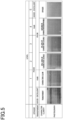
- Fig. 6 shows the evaluation results of Examples 1 to 12 and Comparative Examples 1 to 4.
- the transparent state during transparent driving was at the level of "good” at low to normal temperatures of -30°C to 23°C during driving.
- the opaque state during opaque driving was at the level of "fair” at high temperatures of 90°C to 100°C, confirming that sufficient haze was obtained as the opaque state.
- the transparent state during transparent driving was at the level of "good” at low to high temperatures of -30°C to 100°C during driving, confirming that the haze was low as the transparent state.
- the opaque state during opaque driving was at the level of "excellent” at low to normal temperatures of -30°C to 23°C during driving, confirming that higher haze was obtained than in Examples 1 and 2. Moreover, the opaque state during opaque driving was at the level of "good” at high temperatures of 90°C to 100°C, confirming that sufficient haze was obtained as the opaque state.
- the transparent state during transparent driving was at the level of "good” at low to high temperatures of -30°C to 100°C during driving, confirming that the haze was low as the transparent state.
- the opaque state during opaque driving was at the level of "good” at low to normal temperatures of -30°C to 23°C during driving, confirming that high haze was obtained. Moreover, the opaque state during opaque driving was at the level of "fair” at high temperatures of 90°C to 100°C, confirming that sufficient haze was obtained as the opaque state.
- the transparent state was at the level of "fair” at a low temperature of -30°C.
- the transparent state during transparent driving was at the level of "good” at low to high temperatures of -20°C to 100°C during driving, confirming that the haze was low as the transparent state.
- the opaque state during opaque driving was at the level of "excellent” at low to normal temperatures of -30°C to 23°C, and higher haze was obtained than in Examples 1, 2, 5 and 6. Moreover, the opaque state during opaque driving was at the level of "good” at high temperatures of 90°C to 100°C, confirming that sufficient haze was obtained as the opaque state.
- the opaque state was at the level of "fair” at a low temperature of -30°C; however, the transparent state during transparent driving was at the level of "good” at low to high temperatures of -20°C to 100°C during driving, confirming that the haze was low as the transparent state.
- the opaque state during opaque driving was at the level of "good” at low to high temperatures of -30°C to 90°C, confirming that the haze was high. Moreover, the opaque state during opaque driving was at the level of "fair” at a high temperature of 100°C, confirming that sufficient haze was obtained as the opaque state.
- the transparent state during transparent driving was at the level of "fair” at low to normal temperatures of -30°C to 23°C during driving. Moreover, the transparent state during transparent driving was at the level of "good” at high temperatures of 90°C to 100°C, confirming that the haze was low as the transparent state.
- the opaque state during opaque driving was at the level of "excellent” at low to normal temperatures of -30°C to 23°C, confirming high haze. Moreover, the opaque state during opaque driving was at the level of "good” at high temperatures of 90°C to 100°C, confirming that sufficient haze was obtained as the opaque state.
- the opaque state was at the level of "fair” at low temperatures of -30°C to -20°C.
- the transparent state during transparent driving was at the level of "good” at low to high temperatures of 0°C to 100°C, confirming that the haze was low as the transparent state.
- the opaque state during opaque driving was at the level of "excellent” at low to normal temperatures of -30°C to 23°C during driving. Moreover, the haze in the opaque state was at the level of "fair” at 90°C. Even though the state temporarily became opaque at 100°C, the state did not gradually change to transparent; thus, it was evaluated as the level of "poor.” The reason for this is considered as follows. Specifically, when the temperature of the space 32 reaches 100°C, the temperature of the environment becomes equal to or higher than the nematic-isotropic phase transition temperatures of the liquid crystal compounds of Comparative Examples 1 and 2, and transition occurs from the liquid crystal phase to the isotropic liquid phase.
- the transparent state during transparent driving was at the level of "exellent” at low to normal temperatures of -30°C to 23°C during driving, the haze in the transparent state at 90°C was at the level of "fair,” and the haze in the transparent state at 100°C was at the level of "poor.”
- the reason for this is considered to be that the liquid crystal compound has undergone phase transition to the liquid phase in a temperature environment of 100°C, as described above.
- the opaque state during opaque driving was at the level of "excellent” at low to normal temperatures of -30°C to 23°C during driving.
- the haze in an opaque state was at the level of "good” at high temperatures of 90°C to 100°C.
- the transparent state during transparent driving was at the level of "poor” at low temperatures of -30°C to -20°C during driving.
- the reason for this is considered as follows. Specifically, when the nematic-isotropic phase transition temperature exceeds 150°C, the viscosity rises in a state where the liquid crystal compound is close to the smectic phase in an extremely low-temperature environment such as below zero, and the orientation state is less likely to change.
Landscapes
- Chemical & Material Sciences (AREA)
- Physics & Mathematics (AREA)
- Nonlinear Science (AREA)
- Crystallography & Structural Chemistry (AREA)
- Organic Chemistry (AREA)
- Engineering & Computer Science (AREA)
- Materials Engineering (AREA)
- General Physics & Mathematics (AREA)
- Optics & Photonics (AREA)
- Liquid Crystal (AREA)
- Mathematical Physics (AREA)
- Spectroscopy & Molecular Physics (AREA)
- Chemical Kinetics & Catalysis (AREA)
- Medicinal Chemistry (AREA)
- Polymers & Plastics (AREA)
- Health & Medical Sciences (AREA)
- Laminated Bodies (AREA)
- Addition Polymer Or Copolymer, Post-Treatments, Or Chemical Modifications (AREA)
- Macromonomer-Based Addition Polymer (AREA)
Abstract
Description
- The present disclosure relates to a light control sheet, a light control device, a photosensitive composition, and a method for producing the light control sheet.
- A light control sheet includes a light control layer containing a resin composition and a liquid crystal composition, and a pair of transparent electrode layers that sandwich the light control layer (see, for example, PTL 1). A light control device includes the above light control sheet, and a driving unit that applies a drive voltage to the transparent electrode layers. The orientation state of liquid crystal molecules changes depending on the potential difference between the two transparent electrode layers, whereby the light transmittance of the light control sheet changes.
- PTL 1:
JP 2017-187775 A - The light control sheet may be attached to, for example, building materials, such as glass windows and glass walls, automobile glass windows, or the like. Therefore, the light control sheet is exposed to harsh temperature environments. However, in a conventional light control sheet, the viscosity of the light control layer becomes too high or too low due to temperature changes. As a result, even when the driving unit applies a drive voltage, the light control sheet may not have the required haze.
- A light control sheet for achieving the above object is a liquid crystal-dispersed light control sheet comprising: a light control layer containing a resin composition that partitions voids, and a liquid crystal composition filled in the voids; a pair of transparent electrode layers that sandwich the light control layer; and a pair of transparent support layers that sandwich the pair of transparent electrode layers, the liquid crystal composition being composed of a liquid crystal compound having a nematic-isotropic phase transition temperature of 110°C or greater and 140°C or less, the resin composition comprising an acrylic polymer containing a repeating structure represented by the following general formula (1),

- A light control device for achieving the above object comprises: the light control sheet; and a control unit that controls application of a drive voltage to the transparent electrode layers.
- With each of the above configurations, the resin composition that partitions voids filled with a liquid crystal composition contains a repeating structure represented by the general formula (1). Therefore, acrylate is polymerized to form a resin composition, compatibility between a liquid crystal compound having a nematic-isotropic phase transition temperature of 110°C or greater and 140°C or less and the acrylate can be obtained. Then, the acrylate polymer and the liquid crystal compound can be phase-separated throughout the entire resin composition. As a result, the light control sheet can operate normally over a wider temperature range.
- In the light control sheet, the resin composition may contain a bicycloalkyl group as the saturated alkyl group. Further, in the light control sheet, the bicycloalkyl group may contain an isobornyl group.
- With each of the above configurations, the acrylate contains a bicycloalkyl group that is bulkier than a linear alkyl group. Therefore, phase separation between the acrylate polymer and the liquid crystal compound is promoted, while ensuring compatibility between the acrylate and the liquid crystal composition.
- In the light control sheet, the haze in an opaque state may be 85% or more and the haze in a transparent state may be 6.0 or less at a temperature of -30°C or greater and 100°C or less.
- With the above configuration, the light control sheet can operate normally over a wider temperature range.
- In the light control sheet, the content of the liquid crystal compound contained in the light control layer may be 50 wt%.
- With the above configuration, the content of the liquid crystal compound contained in the light control layer is sufficient, and the light control sheet can operate normally even at low or high temperatures.
- A photosensitive composition for achieving the above object is a photosensitive composition for producing a liquid crystal-dispersed light control layer, the photosensitive composition comprising: an acrylate mixture and a liquid crystal composition, the liquid crystal composition being composed of a liquid crystal compound having a nematic-isotropic phase transition temperature of 110°C or greater and 140°C or less, the acrylate mixture comprising pentaerythritol triacrylate, urethane acrylate, and an acrylate represented by the following general formula (2),
[Chemical Formula 2]
CH2CHCOO-R2 ... (2)
wherein R2 is a saturated alkyl group having 1 or more and 12 or fewer carbon atoms, and the acrylate mixture comprising an acrylate in which the saturated alkyl group is a linear alkyl group and an acrylate in which the saturated alkyl group is a bicycloalkyl group. - A method for producing a light control sheet for achieving the above object is a method for producing a liquid crystal-dispersed light control sheet, the method comprising: a step of applying a photosensitive composition comprising an acrylate mixture and a liquid crystal composition to a transparent support layer of a laminate comprising a transparent electrode layer and the transparent support layer; and a step of applying light of a specific wavelength to the laminate coated with the photosensitive composition and another laminate that are superimposed so that the photosensitive composition is located between the laminates to cure the acrylate mixture, the liquid crystal composition being composed of a liquid crystal compound having a nematic-isotropic phase transition temperature of 110°C or greater and 140°C or less, the acrylate mixture comprising pentaerythritol triacrylate, urethane acrylate, and an acrylate represented by the following general formula (2),
[Chemical Formula 3]
CH2CHCOO-R2 ... (2)
wherein R2 is a saturated alkyl group having 1 or more and 12 or fewer carbon atoms, and the acrylate mixture comprising an acrylate in which the saturated alkyl group is a linear alkyl group and an acrylate in which the saturated alkyl group is a bicycloalkyl group. - With each of the above configurations, compatibility between the liquid crystal compound having a nematic-isotropic phase transition temperature of 110°C or greater and 140°C or less and the acrylate mixture is obtained, and phase separation between the acrylate mixture containing a bicycloalkyl group and the liquid crystal compound is promoted; thus, the acrylate polymer and the liquid crystal compound can be phase-separated throughout the entire resin composition. As a result, the light control sheet can operate normally over a wider temperature range.
- According to the present disclosure, the light control device can operate normally over a wider temperature range.
-
-
Fig. 1 is a diagram illustrating the configuration of a light control device using a light control sheet, mainly a cross-sectional structure of a normal-type light control sheet. -
Fig. 2 is a diagram illustrating the configuration of a light control device using a light control sheet, mainly a cross-sectional structure of a reverse-type light control sheet. -
Fig. 3 is a schematic view of an evaluation device for evaluating the light control sheets of examples and comparative examples. -
Fig. 4 is a front view of a character board used in the evaluation device. -
Fig. 5 is a table for evaluating the opaque and transparent states of the light control sheets of the examples and comparative examples. -
Fig. 6 is a table showing the evaluation results of the light control sheets of the examples and comparative examples. - Referring to the drawings, an embodiment of a light control sheet, a light control device, a photosensitive composition, and a method for producing the light control sheet will be described.
- Referring to
Fig. 1 , the basic structures of the light control sheet and light control device will be described. - The
light control device 100 includes alight control sheet 10, and acontrol unit 20 that controls application of a drive voltage to thelight control sheet 10. Thelight control sheet 10 may have a structure of a normal-type light control sheet 10N, or a structure of a reverse-typelight control sheet 10R.Fig. 1 shows a cross-sectional structure of a normal-type light control sheet 10N. The configuration common to the normal-type light control sheet 10N and the reverse-typelight control sheet 10R will be described as the configuration of thelight control sheet 10. - The normal-type light control sheet 10N includes a
light control layer 11, a firsttransparent electrode layer 12A, a secondtransparent electrode layer 12B, a firsttransparent support layer 13A, and a secondtransparent support layer 13B. The firsttransparent electrode layer 12A and the secondtransparent electrode layer 12B sandwich thelight control layer 11. The firsttransparent support layer 13A and the secondtransparent support layer 13B sandwich thelight control layer 11, and also sandwich the twotransparent electrode layers transparent support layer 13A supports the firsttransparent electrode layer 12A. The secondtransparent support layer 13B supports the secondtransparent electrode layer 12B. - One corner of the surface of the light control sheet 10N is a region where the first
transparent electrode layer 12A is exposed. Afirst terminal unit 15A is connected to this region. Thefirst terminal unit 15A is connected to thecontrol unit 20 through a wire. Further, another corner of the surface of the light control sheet 10N is a region where the secondtransparent electrode layer 12B is exposed. Asecond terminal unit 15B is connected to this region. The secondterminal unit 15B is connected to thecontrol unit 20 through a wire. The firstterminal unit 15A and the secondterminal unit 15B constitute the light control sheet 10N. - The
control unit 20 generates a drive voltage, which is an AC voltage, and applies the drive voltage between the firsttransparent electrode layer 12A and the secondtransparent electrode layer 12B. - The
light control sheet 10 includes a liquid crystal-dispersedlight control layer 11. Thelight control layer 11 contains a resin composition and a liquid crystal composition. An example of thelight control layer 11 is a polymer dispersed liquid crystal (PDLC). In the polymer dispersed liquid crystal, domains, which are a plurality of voids, are dispersed in a resin composition containing a polymer compound. The liquid crystal composition containing the liquid crystal compound fills the domains. Thelight control layer 11 may be a polymer network liquid crystal (PNLC), a nematic curvilinear aligned phase (NCAP), or a combined structure thereof. The polymer network liquid crystal has a three-dimensional mesh polymer network, and holds a liquid crystal compound, which is an example of oriented particles, in voids in the polymer network. The nematic curvilinear aligned phase holds an encapsulated liquid crystal composition in a resin composition. - Next, the material constituting each layer will be described.
- Each of the first
transparent electrode layer 12A and the secondtransparent electrode layer 12B is a conductive transparent layer. The material constituting thetransparent electrode layers - Each of the first
transparent support layer 13A and the secondtransparent support layer 13B is a transparent substrate. Thetransparent support layers - Each of the first
terminal unit 15A and the secondterminal unit 15B may be composed of, for example, a conductive adhesive layer such as a metal tape, a conductive film, or a conductive paste, and a wire substrate such as FPC, or a wire such as a lead wire. - The
light control layer 11 contains a resin composition that partitions voids, and a liquid crystal composition filled in the voids. The main component of the liquid crystal composition is a liquid crystal compound. The nematic-isotropic phase transition temperature of the liquid crystal compound is 110°C or greater and 140°C or less. The liquid crystal compound may be a single compound or a mixture of two or more compounds. When the liquid crystal compound is a mixture, the nematic-isotropic phase transition temperature of all of the compounds constituting the liquid crystal compound may be 110°C or greater and 140°C or less, or the nematic-isotropic phase transition temperature of some of the compounds constituting the liquid crystal compound may be less than 110°C and 140°C or greater. The liquid crystal compound is at least one compound selected from the group consisting of those based on phenyl-cyclohexyls, biphenylcyclohexanes, Schiff bases, azo types, azoxy types, biphenyls, terphenyls, benzoic acid esters, tolan types, pyrimidines, pyridazines, cyclohexanecarboxylic acid esters, dicyanobenzenes, naphthalenes, and dioxanes. - The phenyl-cyclohexane-based liquid crystal compound may be, for example, 4-(4'-n-propylcyclohexyl)-cyanobenzene or 4-(4'-n-pentylcyclohexyl)-cyanobenzene.
- The liquid crystal compound constituting the liquid crystal composition may be a single compound alone or a mixture of several compounds. The liquid crystal composition may contain components other than the liquid crystal compound. Examples of such components other than the liquid crystal compound include viscosity-reducing agents, dichroic dyes, defoaming agents, antioxidants, and weathering agents, such as UV absorbers and light stabilizers. Because the liquid crystal compound constituting the liquid crystal composition is a mixture, the nematic-isotropic phase transition temperature of the liquid crystal compound can be easily adjusted.
- The content (wt%) of the liquid crystal compound in the
light control layer 11 is the ratio of the weight of the liquid crystal compound to the weight of thelight control layer 11. The content of the liquid crystal compound in thelight control layer 11 may be, for example, 30 wt% or more and 80 wt% or less, and may be 50 wt% or more and 80 wt% or less. When it is necessary to increase the contrast, which is the difference between haze during transparent driving and haze during opaque driving in the light control sheet 10N, the content of the liquid crystal compound in thelight control layer 11 is preferably 30 wt% or more, and more preferably 50 wt% or more. When it is necessary to increase the mechanical strength of thelight control layer 11 and the adhesion strength with the transparent electrode layers, the content of the liquid crystal compound in thelight control layer 11 is preferably 80 wt% or less, and more preferably 60 wt% or less. - The resin composition is a cured product among photosensitive compositions. The resin composition is a cured photosensitive compound polymerized by irradiation of light of a specific wavelength, such as ultraviolet light. The resin composition includes a repeating structure represented by the following general formula (1). The repeating structure represented by the general formula (1) is a structure that repeats repeating units. The repeating structure represented by the general formula (1) includes an acrylate-derived repeating unit.

- The bridging group represented by "R1" is a saturated alkyl group having 1 or more and 12 or fewer carbon atoms. The resin composition contains a repeating structure wherein R1 is a linear alkyl group. The resin composition may further contain a repeating structure wherein R1 is a bicycloalkyl group. The degree of polymerization "n" is 2 or more and 500. The resin compound constituting the resin composition may be a homopolymer formed from a single acrylate, a mixture of two or more homopolymers, or a copolymer formed from two or more acrylates. The homopolymer has a single repeating structure. The copolymer has two or more repeating structures. The resin composition may contain a homopolymer having a single repeating structure represented by the general formula (1), or a copolymer having two or more repeating structures represented by the general formula (1).
- Hereinafter, among the resin compounds constituting the resin composition, the polymer wherein the bridging group R1 is a linear alkyl group is referred to as the "first acrylic polymer". The first acrylic polymer may be a homopolymer or part of a copolymer. Further, among the polymers constituting the resin composition, the polymer wherein the bridging group R1 is a cyclic alkyl group is referred to as the "second acrylic polymer". The second acrylic polymer is part of a copolymer.
- The first acrylic polymer is an acrylate polymer. The acrylate for forming the first acrylic polymer is at least one photosensitive compound selected from the group consisting of methyl acrylate, ethyl acrylate, propyl acrylate, butyl acrylate, pentyl acrylate, hexyl acrylate, heptyl acrylate, octyl acrylate, nonyl acrylate, decyl acrylate, undecyl acrylate, and dodecyl acrylate.
- The second acrylic polymer is an acrylate polymer. The acrylate for forming the second acrylic polymer contains a cycloalkyl group, a bicycloalkyl group, or a tricycloalkyl group. The cycloalkyl group-containing acrylate is at least one photosensitive compound selected from the group consisting of cyclopropyl acrylate, cyclobutyl acrylate, cyclopentyl acrylate, cyclohexyl acrylate, cycloheptanyl acrylate, cyclooctyl acrylate, cyclodecanyl acrylate, and cyclododecanyl acrylate.
- The bicycloalkyl group and tricycloalkyl group are polycyclic alkyl groups having a bridged structure in which two carbon atoms that constitute one ring structure are connected with a linear carbon chain. The polycyclic alkyl group may be a bicyclic functional group or a tricyclic functional group. The bicycloalkyl group may contain an isobornyl group. The bicycloalkyl group-containing acrylate is at least one photosensitive compound selected from the group consisting of isobornyl acrylate and bicyclo[3.2.1]octylacrylate. The tricycloalkyl group-containing acrylate is at least one photosensitive compound selected from the group consisting of dicyclopentanyl acrylate and tricyclo[5.2.1.02,6]decane acrylate.
- A liquid crystal compound having a nematic-isotropic phase transition temperature of 110°C or greater and 140°C or less has a structure that is longer in the major axis direction or has more ring structures compared with a liquid crystal compound having a lower transition temperature, and the compatibility between the liquid crystal compound and the acrylates is reduced. When the compatibility between the liquid crystal compound and the acrylates is reduced, the liquid crystal composition is difficult to disperse uniformly in the photosensitive composition for forming the
light control layer 11. When it is necessary to increase the haze during opaque driving, the size of the voids in the resin composition is preferably 0.3 µm or more and 3 µm or less. The size of the voids in the resin composition is the diameter of circles circumscribed by the voids in a cross section including the thickness direction of the resin composition. The size of the voids in the resin composition is, for example, the average value of the diameters of all voids contained in a cross section having a size of 10 µm × 10 µm. The more non-uniformly the liquid crystal composition is dispersed in the photosensitive composition, the more non-uniformly the positions of voids in the resin composition are distributed in the plane direction in which thelight control layer 11 extends, and the voids tend to have various sizes. As a result, in the plane direction in which thelight control layer 11 extends, the variation in the haze increases, or changes in the haze cannot be obtained; thus, the desired haze cannot be obtained during opaque driving. In contrast, since the acrylates for forming the first acrylic polymer and second acrylic polymer have a low molecular weight and contain a saturated alkyl group, which is a non-polar group, they are highly compatible with the liquid crystal compound, which has a high nematic-isotropic phase transition temperature. - When it is necessary to increase the compatibility between the liquid crystal compound and the acrylates, the content of the first acrylic polymer is 20 wt% or more and 90 wt% or less relative to the total solids content of the photosensitive composition. Further, the content of the first acrylic polymer may be 20 wt% or more and 40 wt% or less. When it is necessary to further increase the compatibility and facilitate the phase separation of the liquid crystal compound from the acrylate polymer, the resin composition preferably contains the first acrylic polymer and the second acrylic polymer. In this case, the sum of the content of the first acrylic polymer and the content of the second acrylic polymer is preferably 20 wt% or more and 90 wt% or less relative to the total solid content of the photosensitive composition. In addition, each of the content of the first acrylic polymer and the content of the second acrylic polymer may be 20 wt% or more and 40 wt% or less relative to the total solid content of the photosensitive composition.
- Since the bicycloalkyl group has a bulkier structure than the linear alkyl group and the cycloalkyl group, repulsion caused by steric hindrance etc. occurs between the bicycloalkyl group-containing acrylate and the liquid crystal compound. As a result, at a temperature equal to or lower than the nematic-isotropic phase transition temperature, nematic phase domains formed by the liquid crystal compound are more likely to occur in the polymer, increasing the degree of phase separation. In particular, when increasing the compatibility between the linear alkyl group-containing acrylate and the liquid crystal compound, the content of the liquid crystal compound in the photosensitive composition increases; thus, phase separation may be difficult to progress. Because the photosensitive composition contains both an acrylate having a linear alkyl group and an acrylate having a bicycloalkyl group, the compatibility and phase separation can both be improved.
- Next, referring to
Fig. 2 , the reverse-typelight control sheet 10R will be described.Fig. 2 shows a cross-sectional structure of thelight control sheet 10R. The reverse-typelight control sheet 10R includes alight control layer 11,transparent electrode layers transparent support layers first orientation layer 14A and asecond orientation layer 14B, which are a pair of orientation layers that sandwich thelight control layer 11. Thefirst orientation layer 14A is located between thelight control layer 11 and the firsttransparent electrode layer 12A. Thesecond orientation layer 14B is located between thelight control layer 11 and the secondtransparent electrode layer 12B. That is, the firsttransparent electrode layer 12A and the secondtransparent electrode layer 12B sandwich thelight control layer 11, and also sandwich the orientation layers 14A and 14B. - The orientation layers 14A and 14B are vertical orientation films. When the first
transparent electrode layer 12A and the secondtransparent electrode layer 12B are at equipotential, the orientation layers 14A and 14B orient the liquid crystal compound so that the major axis direction of the liquid crystal compound contained in thelight control layer 11 is along the normal direction to the plane extending parallel to the orientation layers 14A and 14B. On the other hand, when a potential difference is generated between thetransparent electrode layers light control layer 11 to a direction other than the above normal direction. - Examples of the materials constituting the orientation layers 14A and 14B include polyesters such as polyamide, polyimide, polycarbonate, polystyrene, polysiloxane, polyethylene terephthalate, and polyethylene naphthalate, and polyacrylates such as polymethyl methacrylate. Examples of the processing to allow the orientation layers 14A and 14B to function as vertical orientation films include rubbing, polarized light irradiation, and microprocessing.
- In the normal-type light control sheet 10N, when no drive voltage is applied to the
transparent electrode layers transparent electrode layer 12A and the secondtransparent electrode layer 12B are at equipotential, the direction of the major axis direction of the liquid crystal compound contained in thelight control layer 11 is irregular. Therefore, light incident on thelight control layer 11 is scattered due to the large refractive index difference between the resin composition and the liquid crystal composition, and thelight control sheet 10 becomes opaque. On the other hand, when a drive voltage is applied to thetransparent electrode layers transparent electrode layer 12A and the secondtransparent electrode layer 12B, the liquid crystal compound is oriented depending on the potential difference, and the major axis direction of the liquid crystal compound becomes parallel to the direction of the electric field between thetransparent electrode layers light control layer 11. As the applied drive voltage increases within a given range, the transparency of thelight control sheet 10 increases. - In the reverse-type
light control sheet 10R, when no drive voltage is applied to thetransparent electrode layers light control sheet 10 becomes transparent due to the small refractive index difference between the resin composition and the liquid crystal composition. On the other hand, when a drive voltage is applied to thetransparent electrode layers transparent electrode layer 12A and the secondtransparent electrode layer 12B. As a result, due to the large refractive index difference between the resin composition and the liquid crystal composition, light is less likely to pass through thelight control layer 11. As the applied drive voltage increases within a given range, the transparency of thelight control sheet 10 decreases. - The
light control sheet 10 is attached to a transparent member located on the boundary between two spaces, and functions as a partition between the two spaces. The surface to which thelight control sheet 10 is attached may be flat or curved. For example, thelight control sheet 10 may be attached to building materials, such as glass windows, partitions, and glass walls, or vehicle components, such as automobile glass windows. - A method for producing the light control sheet 10N will be described.
- A sheet composed of a first
transparent support layer 13A having a firsttransparent electrode layer 12A on a surface thereof, and a sheet composed of a secondtransparent support layer 13B having a secondtransparent electrode layer 12B on a surface thereof are prepared. The firsttransparent electrode layer 12A and the secondtransparent electrode layer 12B are formed by a known thin film formation method, such as sputtering, vacuum deposition, or coating. - Next, a photosensitive composition is prepared. The photosensitive composition is obtained by mixing and stirring an acrylate represented by the following general formula (2), a liquid crystal composition, a polymerization initiator, and other additives. The photosensitive composition may contain pentaerythritol triacrylate or urethane acrylate for the purpose of, for example, enhancing the mechanical strength of the resin composition.
[Chemical Formula 5]
CH2CHCOO-R2 ... (2)
- The bridging group represented by R2 is a saturated alkyl group having 1 or more and 12 or fewer carbon atoms. The acrylates include acrylates wherein R2 is a linear alkyl group. In addition to the acrylates wherein R2 is a linear alkyl group, the acrylates may further include at least one selected from the group consisting of acrylates wherein R2 is a cycloalkyl group, acrylates wherein R2 is a bicycloalkyl group, and acrylates wherein R2 is a tricycloalkyl group.
- The acrylates wherein R2 is a linear alkyl group are at least one selected from the group consisting of methyl acrylate, ethyl acrylate, propyl acrylate, butyl acrylate, pentyl acrylate, hexyl acrylate, heptyl acrylate, octyl acrylate, nonyl acrylate, decyl acrylate, undecyl acrylate, and dodecyl acrylate.
- The acrylates wherein R2 is a cycloalkyl group are at least one selected from the group consisting of cyclopropyl acrylate, cyclobutyl acrylate, cyclopentyl acrylate, cyclohexyl acrylate, cycloheptanyl acrylate, cyclooctyl acrylate, cyclodecanyl acrylate, and cyclododecanyl acrylate.
- The acrylates wherein R2 is a bicycloalkyl group are at least one selected from the group consisting of isobornyl acrylate and bicyclo[3.2.1]octylacrylate.
- The acrylates wherein R2 is a tricycloalkyl group are at least one selected from the group consisting of dicyclopentanyl acrylate and tricyclo[5.2.1.02,6]decane acrylate.
- A dispersion medium with spacers dispersed therein is applied to at least one of the two sheets, and heated to remove the solvent and disperse the spacers. Moreover, the photosensitive composition is applied to at least one of the two sheets. The photosensitive composition is applied by a known coating method, such as an inkjet method, a gravure coating method, a spin coating method, a slit coating method, a bar coating method, a flexo coating method, a die coating method, a dip coating method, or a roll coating method. Then, one sheet is bonded to the other sheet so that the coating layer of the photosensitive composition is located between the two sheets. The dispersion of the spacers and the dispersion of the photosensitive composition may be carried out as separate steps, or may be carried out as a single step, for example dispersing a photosensitive composition to which spacers are added.
- The laminate of the layer formed by applying the photosensitive composition and the sheets that sandwich the coating layer is irradiated with light of a specific wavelength. The light of a specific wavelength promotes the polymerization reaction of the photosensitive composition. The
light control layer 11 is thus formed. - The laminate is formed into a large sheet, for example, by using the roll-to-roll method. The laminate is cut out in the desired shape according to the application target of the light control sheet 10N, and a first
terminal unit 15A and a secondterminal unit 15B are formed for the cut sheet. The light control sheet 10N is thus formed. - According to the above-described embodiment, the advantageous effects listed below can be achieved.
- (1) The resin composition that partitions voids filled with a liquid crystal composition contains a repeating structure represented by the above general formula (1). Therefore, acrylate is polymerized to form a resin composition, compatibility between a liquid crystal compound having a nematic-isotropic phase transition temperature of 110°C or greater and 140°C or less and the acrylate can be obtained. Then, it is possible to promote phase separation to separate the liquid crystal composition from the acrylate polymer throughout the entire resin composition. As a result, the
light control sheet 10 can operate normally over a wider temperature range. - (2) Because the resin composition further contains a bicycloalkyl group, which is bulkier than a linear alkyl group, phase separation between the acrylate polymer and the liquid crystal composition can be promoted, while ensuring compatibility between the acrylates and the liquid crystal composition.
- (3) The
light control sheet 10 can operate normally over a wider temperature range because the haze in the opaque state is 85% or more and the haze in the transparent state is 6.0 or less at a temperature of -30°C or greater and 100°C or less. - (4) Because the content of the liquid crystal compound contained in the
light control layer 11 is 50 wt%, thelight control sheet 10 can operate normally even at low or high temperatures. - The above embodiments can be performed with the following modifications.
- The
control unit 20 may incorporate a temperature sensor for detecting the temperature of the environment in which thelight control sheet 10 is used, or may be connected to such a temperature sensor. In this aspect, thecontrol unit 20 obtains the temperature detected by the temperature sensor, and when the obtained temperature is, for example, -30°C or greater and 100°C or less, a drive voltage may be applied to thelight control sheet 10. Further, thecontrol unit 20 may include driving data to associate the temperature of the use environment with the magnitude of driving voltage. Then, thecontrol unit 20 may refer to the driving data, and may apply a driving voltage associated with the temperature detected by the temperature sensor to thelight control sheet 10. - In addition to the transparent and opaque states, the state of the
light control sheet 10 may be switched to a third state in which the light transmittance is intermediate between these states. - The
light control sheet 10 may be used in an opaque state as a screen onto which images etc. are projected. The higher the light shielding ratio of thelight control sheet 10 in the opaque state, the more clearly images can be projected by suppressing the transmission of light for projection. - Referring to
Fig. 3 , Examples 1 to 12, which are examples of the above embodiment, and Comparative Examples 1 to 4 will be described in detail. Thelight control sheet 10 of the present disclosure is not limited to these examples. - The light control sheets of Examples 1 to 12 and Comparative Examples 1 to 4 are of normal type.
- Methyl acrylate was used as the acrylate for forming the first acrylic polymer contained in the photosensitive composition for forming the light control layer. As the acrylates in the photosensitive composition of Example 1, 16 wt% of methyl acrylate (produced by Tokyo Chemical Industry Co., Ltd.), 11 wt% of pentaerythritol triacrylate (product name: A-TMM-3L, produced by Shin Nakamura Chemical Co., Ltd.), and 21 wt% of urethane acrylate (product name: CN929, produced by Sartomer), relative to the total amount of the photosensitive composition, were added to the photosensitive composition. The acrylate for forming the second acrylic polymer was not added to the photosensitive composition of Example 1. Moreover, as the polymerization initiator in the photosensitive composition of Example 1, a polymerization initiator was added to the photosensitive composition so that the amount of 1-hydroxycyclohexyl phenyl ketone (product name: Irg184, produced by BASF) was 1 wt% relative to the total amount of the photosensitive composition.
- Further, as the liquid crystal compound in the photosensitive composition of Example 1, a phenyl-cyclohexyl-based liquid crystal compound having a nematic-isotropic phase transition temperature of 110°C (MNC-6609, produced by Merck) at 50 wt% relative to the total amount of the photosensitive composition was added to the photosensitive composition. Then, the photosensitive composition of Example 1 was produced as a mixture of the acrylates, the liquid crystal composition, and the polymerization initiator, and a polymethyl methacrylate filler (product name: SSX-115, produced by Sekisui Kasei Co., Ltd., diameter: 15 µm) was used as spacers.
- Moreover, a pair of sheets each containing a transparent support layer with a thickness of 125 µm made of polyethylene terephthalate and a transparent electrode layer with a thickness of 30 nm made of indium tin oxide (ITO) were prepared.
- The photosensitive composition of Example 1 was applied to one sheet. The other sheet was superimposed on the sheet coated with the photosensitive composition of Example 1, thereby sandwiching the coating layer between two orientation layers. Then, using a high-pressure mercury lamp with an illuminance of 10 mW/cm2, the laminate was irradiated with ultraviolet light through one of the transparent support layers and one of the transparent electrode layers. The polymerization temperature of the photosensitive compound was set to 15°C or greater and 30°C or less. The acrylates were thus polymerized and cured to obtain a light control sheet of Example 1 including a resin composition partitioning voids, and a liquid crystal composition filled in the voids.
- A light control sheet of Example 2 was obtained in the same manner as in Example 1, except that the acrylate for forming the first acrylic polymer was changed to 16 wt% of dodecyl acrylate (produced by Tokyo Chemical Industry Co., Ltd.).
- The content of methyl acrylate, which was the acrylate for forming the first acrylic polymer, was changed to 11 wt%. Moreover, as the acrylate for forming the second acrylic polymer, 18 wt% of isobornyl acrylate (product name: A-IB, produced by Shin Nakamura Chemical Co., Ltd.) was added to the photosensitive composition. Further, the content of pentaerythritol triacrylate was changed to 6 wt%, and the content of urethane acrylate was changed to 13 wt%. Except for these, a light control sheet of Example 3 was obtained in the same manner as in Example 1.
- The acrylate for forming the first acrylic polymer was changed to 11 wt% of dodecyl acrylate (same as above). Moreover, as the acrylate for forming the second acrylic polymer, 18 wt% of isobornyl acrylate (product name: A-IB, produced by Shin Nakamura Chemical Co., Ltd.) was added to the photosensitive composition. Further, the content of pentaerythritol triacrylate was changed to 6 wt%, and the content urethane acrylate was changed to 13 wt%. Except for these, a light control sheet of Example 4 was obtained in the same manner as in Example 1.
- Examples 5 to 8 below are respectively different from Examples 1 to 4 in terms of the nematic-isotropic phase transition temperature of the liquid crystal compound.
- A light control sheet of Example 5 was obtained in the same manner as in Example 1, except that the nematic-isotropic phase transition temperature of the liquid crystal compound in Example 1 was changed to 125°C.
- A light control sheet of Example 6 was obtained in the same manner as in Example 1, except that the nematic-isotropic phase transition temperature of the liquid crystal compound in Example 2 was changed to 125°C.
- A light control sheet of Example 7 was obtained in the same manner as in Example 1, except that the nematic-isotropic phase transition temperature of the liquid crystal compound in Example 3 was changed to 125°C.
- A light control sheet of Example 8 was obtained in the same manner as in Example 1, except that the nematic-isotropic phase transition temperature of the liquid crystal compound in Example 4 was changed to 125°C.
- Examples 9 to 12 below are respectively different from Examples 1 to 4 in terms of the nematic-isotropic phase transition temperature of the liquid crystal compound.
- A light control sheet of Example 9 was obtained in the same manner as in Example 1, except that the nematic-isotropic phase transition temperature of the liquid crystal compound in Example 1 was changed to 140°C.
- A light control sheet of Example 10 was obtained in the same manner as in Example 1, except that the nematic-isotropic phase transition temperature of the liquid crystal compound in Example 2 was changed to 140°C.
- A light control sheet of Example 11 was obtained in the same manner as in Example 1, except that the nematic-isotropic phase transition temperature of the liquid crystal compound in Example 3 was changed to 140°C.
- A light control sheet of Example 12 was obtained in the same manner as in Example 1, except that the nematic-isotropic phase transition temperature of the liquid crystal compound in Example 4 was changed to 140°C.
- Comparative Examples 1 to 4 below are different from the above examples in terms of the nematic-isotropic phase transition temperature of the liquid crystal compound; the nematic-isotropic phase transition temperature of the liquid crystal compound was changed to be outside the range of 110°C or greater and 140°C or less.
- A light control sheet of Comparative Example 1 was obtained in the same manner as in Example 3, except that the nematic-isotropic phase transition temperature of the liquid crystal compound was changed to 100°C.
- A light control sheet of Comparative Example 2 was obtained in the same manner as in Example 1, except that the nematic-isotropic phase transition temperature of the liquid crystal compound was changed to 100°C, the acrylates for forming the first and second acrylic polymers were not added to the photosensitive composition, the content of pentaerythritol triacrylate was changed to 15 wt%, and the content of urethane acrylate was changed to 33 wt%.
- A light control sheet of Comparative Example 3 was obtained in the same manner as in Example 3, except that the nematic-isotropic phase transition temperature of the liquid crystal compound was changed to 150°C.
- A light control sheet of Comparative Example 4 was obtained in the same manner as in Example 1, except that the acrylates for forming the first and second acrylic polymers were not added to the photosensitive composition, the content of pentaerythritol triacrylate was changed to 11 wt%, and the content of the urethane acrylate was changed to 21 wt%.
- For the light control sheets of Examples 1 to 12 and Comparative Examples 1 to 4, changes in the optical characteristics during driving were observed while changing the temperature of the space where the light control sheet was installed within the range of -30°C or greater and 100°C or less. The haze measured by a haze meter tends to be affected by temperature. For this reason, a
determination device 30 was produced. -
Fig. 4 shows adetermination device 30 for determining the transparency and opacity of the light control sheet. Thedetermination device 30 includes ahousing 31 having aspace 32 whose temperature can be adjusted by a heater or the like, awindow 33 provided in thehousing 31, and acharacter board 34 arranged inside thespace 32. Thewindow 33 is made of glass. Thecharacter board 34 displays multiple patterns of predetermined characters with different character colors and character background colors. Asample 35 is located between thewindow 33 and thecharacter board 34. Thecharacter board 34 displays multiple patterns of "TOPPAN" (registered trademark), which is the logo of "Toppan Inc.", with different character colors and character background colors. -
Samples 35 were produced from the light control sheets of Examples 1 to 12 and Comparative Examples 1 to 4. In eachsample 35, two cuts were made at the corner of one side of the light control sheet and the corner of the opposite side thereof to expose the first transparent electrode layer and the second transparent electrode layer, thereby forming terminal units. Then, the terminal units were joined to the exposed first transparent electrode layer and second transparent electrode layer, and the terminal units were each connected to acontrol device 36 throughdifferent wires 37. Thecontrol device 36 is a device that controls the drive voltage applied to the transparent electrode layers. - First, the
sample 35 was installed in a position in which anobserver 39 could visually observe thesample 35 through thewindow 33. Further, an AC voltage was applied to thesample 35 from 0 V at a frequency of 50 Hz, and the voltage was increased until the haze of thesample 35 saturated. During transparent driving, the temperature of thespace 32 in which thesample 35 was installed was adjusted to -30°C, and that temperature was maintained. Then, while visually observing thesample 35, the observer waited until the haze increased and saturated while no drive voltage was applied to the transparent electrode layers of thesample 35. When the haze saturated, it was determined whether the characters displayed on thecharacter board 34 were legible through thesample 35, and the haze of thesample 35 during opaque driving was evaluated. - As shown in
Fig. 5 , the clarity of characters viewed through eachsample 35 was classified as one of "level 0" to "level 5". In this case, the state in which thesample 35 was completely transparent and the characters on thecharacter board 34 were clearly legible was classified as "level 0", the state in which thesample 35 was slightly turbid but the characters were clearly legible was classified as "level 1", the state in which 50% or more and less than 100% of the characters were legible was classified as "level 2", the state in which more than 0% and less than 50% of the characters were legible was classified as "level 3", the state in which although the entire characters were not legible, the outline of the characters was identifiable was classified as "level 4", and the opaque state in which no characters were legible was classified as "level 5". - In the evaluation of the opaque state, examples in which the states of "
level 0" to "level 3" were maintained were judged as "poor." Further, in the evaluation of the opaque state, examples in which the state of "level 4" was maintained were judged as "fair." Moreover, in the evaluation of the opaque state, examples in which the state of "level 5" was maintained were judged as "good," and examples in which particularly high haze was maintained were judged as "excellent." - Similarly, from the state of turning off the drive voltage, the drive voltage was applied to reduce the haze, and the observer waited until the haze stabilized. When the haze stabilized, it was determined whether the characters displayed on the
character board 34 were legible through thesample 35, and the haze of thesample 35 during transparent driving was evaluated. - As shown in
Fig. 5 , in the evaluation of the transparent state, examples in which the transparent states of "level 2" to "level 5" were maintained were judged as "poor." Further, in the evaluation of the transparent state, examples in which the transparent state of "level 1" was maintained were judged as "fair," examples in which the transparent state of "level 0" was maintained were judged as "good," and examples in which particularly high transparency and low haze were maintained were judged as "excellent." - After evaluating the opaque and transparent states at -30°C, the temperature was adjusted step by step in the order of -20°C, 0°C, 23°C, 90°C, and 100°C. Each time the temperature was adjusted, the drive voltage was turned off to provide transparent driving, then the drive voltage was applied, and the state during opaque driving was evaluated when the haze had stabilized. In addition, after the drive voltage was applied and the haze stabilized, the drive voltage was turned off, and the state during transparent driving was evaluated when the haze had stabilized.
- Using a temperature of 23°C as a reference, the haze from "
level 0" to "level 5" was measured using a haze meter (NDH-7000SP, produced by Suga Test Instruments Co., Ltd.). As a result, the haze was 97% or more at the level of "excellent," the haze was 90% or more and less than 97% at the level of "good," the haze was 85% or more and less than 90% at the level of "fair," and the haze was less than 85% at the level of "poor." In the transparent state, the haze was 5.0% or less at the level of "excellent," the haze was 5.0% or more and less than 5.5% at the level of "good," the haze was 5.5% or more and less than 6.0% at the level of "fair," and the haze was 6.0% or more at the level of "poor." -
Fig. 6 shows the evaluation results of Examples 1 to 12 and Comparative Examples 1 to 4. In the light control sheets of Examples 1 and 2, the transparent state during transparent driving was at the level of "good" at low to normal temperatures of -30°C to 23°C during driving. Moreover, the opaque state during opaque driving was at the level of "fair" at high temperatures of 90°C to 100°C, confirming that sufficient haze was obtained as the opaque state. - In addition, in the light control sheets of Examples 1 and 2, the transparent state during transparent driving was at the level of "good" at low to high temperatures of -30°C to 100°C during driving, confirming that the haze was low as the transparent state.
- Therefore, it was confirmed that for the light control sheets of Examples 1 and 2, good and stable haze in the opaque state and good and stable haze in the transparent state, as well as good contrast were obtained in a wide temperature range of -30°C to 100°C.
- In the light control sheets of Examples 3 and 4, which contained isobornyl acrylate, the opaque state during opaque driving was at the level of "excellent" at low to normal temperatures of -30°C to 23°C during driving, confirming that higher haze was obtained than in Examples 1 and 2. Moreover, the opaque state during opaque driving was at the level of "good" at high temperatures of 90°C to 100°C, confirming that sufficient haze was obtained as the opaque state.
- In addition, in the light control sheets of Examples 3 and 4, the transparent state during transparent driving was at the level of "good" at low to high temperatures of -30°C to 100°C during driving, confirming that the haze was low as the transparent state.
- Therefore, it was confirmed that for the light control sheets of Examples 3 and 4, good and stable haze in the opaque state and good and stable haze in the transparent state, as well as good contrast were obtained in a wide temperature range of -30°C to 100°C.
- In the light control sheets of Examples 5 and 6, the opaque state during opaque driving was at the level of "good" at low to normal temperatures of -30°C to 23°C during driving, confirming that high haze was obtained. Moreover, the opaque state during opaque driving was at the level of "fair" at high temperatures of 90°C to 100°C, confirming that sufficient haze was obtained as the opaque state.
- In addition, in the light control sheets of Examples 5 and 6, the transparent state was at the level of "fair" at a low temperature of -30°C. The transparent state during transparent driving was at the level of "good" at low to high temperatures of -20°C to 100°C during driving, confirming that the haze was low as the transparent state.
- Therefore, it was confirmed that for the light control sheets of Examples 5 and 6, good and stable haze in the opaque state and good and stable haze in the transparent state, as well as good contrast were obtained in a wide temperature range of -30°C to 100°C.
- In the light control sheets of Examples 7 and 8, which contained isobornyl acrylate, the opaque state during opaque driving was at the level of "excellent" at low to normal temperatures of -30°C to 23°C, and higher haze was obtained than in Examples 1, 2, 5 and 6. Moreover, the opaque state during opaque driving was at the level of "good" at high temperatures of 90°C to 100°C, confirming that sufficient haze was obtained as the opaque state.
- In addition, in the light control sheets of Examples 7 and 8, the opaque state was at the level of "fair" at a low temperature of -30°C; however, the transparent state during transparent driving was at the level of "good" at low to high temperatures of -20°C to 100°C during driving, confirming that the haze was low as the transparent state.
- Therefore, it was confirmed that for the light control sheets of Examples 7 and 8, good and stable haze in the opaque state and good and stable haze in the transparent state, as well as good contrast were obtained in a wide temperature range of -30°C to 100°C.
- In the light control sheets of Examples 9 and 10, the opaque state during opaque driving was at the level of "good" at low to high temperatures of -30°C to 90°C, confirming that the haze was high. Moreover, the opaque state during opaque driving was at the level of "fair" at a high temperature of 100°C, confirming that sufficient haze was obtained as the opaque state.
- In addition, in the light control sheets of Examples 9 and 10, the transparent state during transparent driving was at the level of "fair" at low to normal temperatures of -30°C to 23°C during driving. Moreover, the transparent state during transparent driving was at the level of "good" at high temperatures of 90°C to 100°C, confirming that the haze was low as the transparent state.
- Therefore, it was confirmed that for the light control sheets of Examples 9 and 10, good and stable haze in the opaque state and good and stable haze in the transparent state, as well as good contrast were obtained in a wide temperature range of -30°C to 100°C. Moreover, compared with Examples 5 and 6, in which the nematic-isotropic phase transition temperature was 125°C, the haze in the opaque state at 90°C was further increased, and the haze in the transparent state at -20°C was slightly higher.
- In the light control sheets of Examples 11 and 12, which contained isobornyl acrylate, the opaque state during opaque driving was at the level of "excellent" at low to normal temperatures of -30°C to 23°C, confirming high haze. Moreover, the opaque state during opaque driving was at the level of "good" at high temperatures of 90°C to 100°C, confirming that sufficient haze was obtained as the opaque state.
- In addition, in the light control sheets of Examples 11 and 12, the opaque state was at the level of "fair" at low temperatures of -30°C to -20°C. The transparent state during transparent driving was at the level of "good" at low to high temperatures of 0°C to 100°C, confirming that the haze was low as the transparent state.
- Therefore, it was confirmed that for the light control sheets of Examples 11 and 12, good and stable haze in the opaque state and good and stable haze in the transparent state, as well as good contrast were obtained in a wide temperature range of -30°C to 100°C.
- In the light control sheet of Comparative Example 1, the opaque state during opaque driving was at the level of "excellent" at low to normal temperatures of -30°C to 23°C during driving. Moreover, the haze in the opaque state was at the level of "fair" at 90°C. Even though the state temporarily became opaque at 100°C, the state did not gradually change to transparent; thus, it was evaluated as the level of "poor." The reason for this is considered as follows. Specifically, when the temperature of the
space 32reaches 100°C, the temperature of the environment becomes equal to or higher than the nematic-isotropic phase transition temperatures of the liquid crystal compounds of Comparative Examples 1 and 2, and transition occurs from the liquid crystal phase to the isotropic liquid phase. - In addition, in the light control sheet of Comparative Example 1, the transparent state during transparent driving was at the level of "exellent" at low to normal temperatures of -30°C to 23°C during driving, the haze in the transparent state at 90°C was at the level of "fair," and the haze in the transparent state at 100°C was at the level of "poor." The reason for this is considered to be that the liquid crystal compound has undergone phase transition to the liquid phase in a temperature environment of 100°C, as described above.
- In the light control sheet of Comparative Example 2, since the resin composition did not have the first acrylic polymer and second acrylic polymer, the compatibility between the acrylates and the liquid crystal composition in the resin composition was low, and the photosensitive composition was turbid. For this reason, it was evaluated that haze control was impossible.
- In the light control sheet of Comparative Example 3, the opaque state during opaque driving was at the level of "excellent" at low to normal temperatures of -30°C to 23°C during driving. The haze in an opaque state was at the level of "good" at high temperatures of 90°C to 100°C.
- In addition, in the light control sheet of Comparative Example 3, the transparent state during transparent driving was at the level of "poor" at low temperatures of -30°C to -20°C during driving. The reason for this is considered as follows. Specifically, when the nematic-isotropic phase transition temperature exceeds 150°C, the viscosity rises in a state where the liquid crystal compound is close to the smectic phase in an extremely low-temperature environment such as below zero, and the orientation state is less likely to change.
- As with the light control sheet of Comparative Example 2, in the light control sheet of Comparative Example 4, the compatibility between the resin composition and the liquid crystal composition was low, and the photosensitive composition was turbid. For this reason, it was evaluated that haze control was impossible.
-
- 100
- Light control device
- 10
- Light control sheet
- 11
- Light control layer
- 12A, 12B
- Transparent electrode layer
- 13A, 13B
- Transparent support layer
Claims (8)
- A liquid crystal-dispersed light control sheet comprising:a light control layer containing a resin composition that partitions voids, and a liquid crystal composition filled in the voids;a pair of transparent electrode layers that sandwich the light control layer; anda pair of transparent support layers that sandwich the pair of transparent electrode layers,the liquid crystal composition being composed of a liquid crystal compound having a nematic-isotropic phase transition temperature of 110°C or greater and 140°C or less,the resin composition comprising an acrylic polymer containing a repeating structure represented by the following general formula (1),
 wherein R1 is a saturated alkyl group having 1 or more and 12 or fewer carbon atoms, andthe resin composition comprising, in the acrylic polymer, a moiety in which the saturated alkyl group is a linear alkyl group.
 - The light control sheet according to claim 1, wherein the resin composition comprises a moiety in which the saturated alkyl group is a bicycloalkyl group.
- The light control sheet according to claim 2, wherein the bicycloalkyl group contains an isobornyl group.
- The light control sheet according to any one of claims 1 to 3, wherein the light control sheet has a haze in an opaque state of 85% or more and a haze in a transparent state of 6.0 or less at a temperature of -30°C or greater and 100°C or less.
- The light control sheet according to any one of claims 1 to 4, wherein the content of the liquid crystal compound contained in the light control layer is 50 wt% or more.
- A photosensitive composition for producing a liquid crystal-dispersed light control layer, the photosensitive composition comprising:an acrylate mixture; anda liquid crystal composition,the liquid crystal composition being composed of a liquid crystal compound having a nematic-isotropic phase transition temperature of 110°C or greater and 140°C or less,the acrylate mixture comprising pentaerythritol triacrylate, urethane acrylate, and an acrylate represented by the following general formula (2),
[Chemical Formula 2]
CH2CHCOO-R2 ... (2)
wherein R2 is a saturated alkyl group having 1 or more and 12 or fewer carbon atoms, andthe acrylate mixture comprising an acrylate in which the saturated alkyl group is a linear alkyl group and an acrylate in which the saturated alkyl group is a bicycloalkyl group. - A light control device comprising:the light control sheet according to any one of claims 1 to 5; anda control unit that controls application of a drive voltage to the transparent electrode layers.
- A method for producing a liquid crystal-dispersed light control sheet, the method comprising:a step of applying a photosensitive composition comprising an acrylate mixture and a liquid crystal composition to a transparent support layer of a laminate comprising a transparent electrode layer and the transparent support layer; anda step of applying light of a specific wavelength to the laminate coated with the photosensitive composition and another laminate that are superimposed so that the photosensitive composition is located between the laminates to cure the acrylate mixture,the liquid crystal composition being composed of a liquid crystal compound having a nematic-isotropic phase transition temperature of 110°C or greater and 140°C or less,the acrylate mixture comprising pentaerythritol triacrylate, urethane acrylate, and an acrylate represented by the following general formula (2),
[Chemical Formula 3]
CH2CHCOO-R2 ... (2)
wherein R2 is a saturated alkyl group having 1 or more and 12 or fewer carbon atoms, andthe acrylate mixture comprising an acrylate in which the saturated alkyl group is a linear alkyl group and an acrylate in which the saturated alkyl group is a bicycloalkyl group.
Applications Claiming Priority (2)
| Application Number | Priority Date | Filing Date | Title |
|---|---|---|---|
| JP2021060925A JP7099578B1 (en) | 2021-03-31 | 2021-03-31 | A dimming sheet, a dimming device, a photosensitive composition, and a method for manufacturing a dimming sheet. |
| PCT/JP2022/016755 WO2022211069A1 (en) | 2021-03-31 | 2022-03-31 | Light control sheet, light control device, photosensitive composition, and method for manufacturing light control sheet |
Publications (3)
| Publication Number | Publication Date |
|---|---|
| EP4318113A1 true EP4318113A1 (en) | 2024-02-07 |
| EP4318113A4 EP4318113A4 (en) | 2024-10-02 |
| EP4318113B1 EP4318113B1 (en) | 2025-10-22 |
Family
ID=82384830
Family Applications (1)
| Application Number | Title | Priority Date | Filing Date |
|---|---|---|---|
| EP22781279.9A Active EP4318113B1 (en) | 2021-03-31 | 2022-03-31 | Light control sheet, light control device, photosensitive composition, and method for manufacturing light control sheet |
Country Status (5)
| Country | Link |
|---|---|
| US (1) | US12422715B2 (en) |
| EP (1) | EP4318113B1 (en) |
| JP (2) | JP7099578B1 (en) |
| CN (1) | CN117015738A (en) |
| WO (1) | WO2022211069A1 (en) |
Families Citing this family (2)
| Publication number | Priority date | Publication date | Assignee | Title |
|---|---|---|---|---|
| JP7099578B1 (en) * | 2021-03-31 | 2022-07-12 | 凸版印刷株式会社 | A dimming sheet, a dimming device, a photosensitive composition, and a method for manufacturing a dimming sheet. |
| JP7484976B2 (en) * | 2022-07-29 | 2024-05-16 | Toppanホールディングス株式会社 | Light control sheets and screens |
Family Cites Families (25)
| Publication number | Priority date | Publication date | Assignee | Title |
|---|---|---|---|---|
| JPH02278230A (en) * | 1989-03-10 | 1990-11-14 | Merck Patent Gmbh | Electrooptical liquid crystal system |
| JPH05188355A (en) * | 1991-07-09 | 1993-07-30 | Dainippon Ink & Chem Inc | Liquid crystal device and manufacturing method thereof |
| JP2933805B2 (en) | 1992-09-30 | 1999-08-16 | シャープ株式会社 | Polymer-dispersed liquid crystal composite film, liquid crystal display device, and method of manufacturing the same |
| JPH06194633A (en) * | 1992-12-25 | 1994-07-15 | Dainippon Ink & Chem Inc | Liquid crystal device manufacturing method |
| JPH0756147A (en) * | 1993-08-18 | 1995-03-03 | Mitsubishi Chem Corp | Light control material and light control element comprising the same |
| JP3596039B2 (en) * | 1994-08-15 | 2004-12-02 | 大日本インキ化学工業株式会社 | Liquid crystal device |
| US5731404A (en) | 1995-11-01 | 1998-03-24 | E. I. Du Pont De Nemours And Company | Polyimide film from pyromellitic dianhydride and a bis(4-aminophenoxy) aromatic compound as an alignment layer for liquid crystal displays |
| US5906770A (en) * | 1996-02-26 | 1999-05-25 | Lucent Technologies Inc. | Polymer-dispersed liquid crystal composition |
| JP5013635B2 (en) * | 2000-05-08 | 2012-08-29 | メルク パテント ゲゼルシャフト ミット ベシュレンクテル ハフツング | Liquid crystal medium and liquid crystal display |
| JP4736217B2 (en) * | 2001-03-28 | 2011-07-27 | Dic株式会社 | Side chain radically polymerizable compound and liquid crystal device using the same |
| JP4630954B2 (en) * | 2007-05-22 | 2011-02-09 | 株式会社ビジョンマルチメディアテクノロジ | Polymer / liquid crystal composite material |
| CN101928570B (en) * | 2010-05-19 | 2013-01-09 | 江苏和成显示科技股份有限公司 | Composition for preparing polymer dispersed liquid crystal |
| CN107429164A (en) * | 2014-11-06 | 2017-12-01 | 哥兹有限公司 | Bistable liquid crystal comprising metallomesogen primitive disperses body device and its application |
| WO2017071793A1 (en) * | 2015-10-30 | 2017-05-04 | Merck Patent Gmbh | Liquid-crystal medium |
| CN105418854A (en) * | 2015-12-30 | 2016-03-23 | 石家庄诚志永华显示材料有限公司 | PDLC composition with high bonding force |
| JP6996104B2 (en) | 2016-04-05 | 2022-01-17 | 凸版印刷株式会社 | Dimming sheet |
| TW201807165A (en) * | 2016-04-13 | 2018-03-01 | 馬克專利公司 | Composition for nanoencapsulation and nanocapsules comprising a liquid-crystalline medium |
| US20210261864A1 (en) | 2016-08-04 | 2021-08-26 | Jnc Corporation | Material for liquid-crystal device, and liquid-crystal device |
| JP7036029B2 (en) * | 2016-12-06 | 2022-03-15 | Jnc株式会社 | Liquid crystal complex and liquid crystal dimming element |
| EP3553595A1 (en) * | 2016-12-08 | 2019-10-16 | JNC Corporation | Reverse mode liquid crystal device |
| CN107011923A (en) * | 2017-05-04 | 2017-08-04 | 北京科技大学 | A kind of preparation method of carbon nano tube-doped polymer dispersed liquid crystal film |
| CN111433323B (en) * | 2017-12-06 | 2024-03-22 | 默克专利股份有限公司 | Liquid-crystalline medium for switching elements |
| CN108594509B (en) * | 2018-06-07 | 2019-09-10 | 珠海兴业新材料科技有限公司 | A kind of wide warm light modulation film and preparation method thereof |
| JP7099578B1 (en) * | 2021-03-31 | 2022-07-12 | 凸版印刷株式会社 | A dimming sheet, a dimming device, a photosensitive composition, and a method for manufacturing a dimming sheet. |
| CN118339600A (en) * | 2021-12-23 | 2024-07-12 | 凸版控股株式会社 | Display device |
-
2021
- 2021-03-31 JP JP2021060925A patent/JP7099578B1/en active Active
-
2022
- 2022-03-31 EP EP22781279.9A patent/EP4318113B1/en active Active
- 2022-03-31 WO PCT/JP2022/016755 patent/WO2022211069A1/en not_active Ceased
- 2022-03-31 CN CN202280018466.7A patent/CN117015738A/en active Pending
- 2022-06-30 JP JP2022105420A patent/JP7428207B2/en active Active
-
2023
- 2023-09-28 US US18/476,440 patent/US12422715B2/en active Active
Also Published As
| Publication number | Publication date |
|---|---|
| US20240027836A1 (en) | 2024-01-25 |
| JP7099578B1 (en) | 2022-07-12 |
| JP7428207B2 (en) | 2024-02-06 |
| CN117015738A (en) | 2023-11-07 |
| US12422715B2 (en) | 2025-09-23 |
| EP4318113A4 (en) | 2024-10-02 |
| EP4318113B1 (en) | 2025-10-22 |
| JP2022159271A (en) | 2022-10-17 |
| WO2022211069A1 (en) | 2022-10-06 |
| JP2022156968A (en) | 2022-10-14 |
Similar Documents
| Publication | Publication Date | Title |
|---|---|---|
| US10101617B2 (en) | Transparent electrode for electronic displays | |
| US12422715B2 (en) | Light control sheet, light control device, photosensitive composition, and method for producing light control sheet | |
| US9229253B2 (en) | Electronically switchable privacy film and display device having same | |
| TWI503392B (en) | Pressure sensitive adhesive | |
| KR101758420B1 (en) | Adhesive composition, adhesive film prepared using the same and optical display apparatus comprising the same | |
| ITMI951226A1 (en) | POLYMER STABILIZED LIQUID CRYSTALS (PSLC) AND FLEXIBLE DEVICES FOR THEM | |
| JP7609082B2 (en) | Light-adjusting sheet and method for manufacturing the same | |
| WO2008100460A1 (en) | Two-layer transparent electrostatic charge dissipating coating | |
| KR20100102148A (en) | Liquid crystal display and method of manufacturing same | |
| JP2017090677A (en) | Gel electrolyte and electrochromic device | |
| CN114341718A (en) | Pattern film, transmittance variable device including the same, and method for producing transmittance variable device | |
| EP4465119A1 (en) | Light control sheet | |
| JP2013213953A (en) | Dimmer device | |
| US6383577B1 (en) | Reverse mode electro-optical film composed of one mutual dispersion of polymers and liquid crystals | |
| US12455471B2 (en) | Light control sheet | |
| EP4502717A1 (en) | Light dimming device | |
| JP7533549B2 (en) | Light-adjusting sheet, photosensitive composition, and method for producing light-adjusting sheet | |
| EP4589374A1 (en) | Light control sheet, light control device and method for producing light control sheet | |
| JP2001264515A (en) | Interference prevention coated substrate | |
| WO2025211157A1 (en) | Light control sheet, light control device, and method for producing light control sheet | |
| JP4301052B2 (en) | Ultraviolet curable resin composition, cured product and laminate | |
| CN119856106A (en) | Dimming sheet | |
| JPH04365018A (en) | Electro-chromic display element | |
| JPS63158708A (en) | Transparent conductive laminate | |
| JPH04310926A (en) | Electrochromic display element and its manufacture |
Legal Events
| Date | Code | Title | Description |
|---|---|---|---|
| STAA | Information on the status of an ep patent application or granted ep patent |
Free format text: STATUS: THE INTERNATIONAL PUBLICATION HAS BEEN MADE |
|
| PUAI | Public reference made under article 153(3) epc to a published international application that has entered the european phase |
Free format text: ORIGINAL CODE: 0009012 |
|
| STAA | Information on the status of an ep patent application or granted ep patent |
Free format text: STATUS: REQUEST FOR EXAMINATION WAS MADE |
|
| 17P | Request for examination filed |
Effective date: 20230804 |
|
| AK | Designated contracting states |
Kind code of ref document: A1 Designated state(s): AL AT BE BG CH CY CZ DE DK EE ES FI FR GB GR HR HU IE IS IT LI LT LU LV MC MK MT NL NO PL PT RO RS SE SI SK SM TR |
|
| DAV | Request for validation of the european patent (deleted) | ||
| DAX | Request for extension of the european patent (deleted) | ||
| A4 | Supplementary search report drawn up and despatched |
Effective date: 20240829 |
|
| RIC1 | Information provided on ipc code assigned before grant |
Ipc: C08F 222/10 20060101ALI20240823BHEP Ipc: B32B 27/30 20060101ALI20240823BHEP Ipc: B32B 27/08 20060101ALI20240823BHEP Ipc: C09K 19/54 20060101ALI20240823BHEP Ipc: G02F 1/13 20060101ALI20240823BHEP Ipc: C08F 220/18 20060101ALI20240823BHEP Ipc: G02F 1/1334 20060101AFI20240823BHEP |
|
| GRAP | Despatch of communication of intention to grant a patent |
Free format text: ORIGINAL CODE: EPIDOSNIGR1 |
|
| STAA | Information on the status of an ep patent application or granted ep patent |
Free format text: STATUS: GRANT OF PATENT IS INTENDED |
|
| RIC1 | Information provided on ipc code assigned before grant |
Ipc: C08F 222/10 20060101ALI20250417BHEP Ipc: B32B 27/30 20060101ALI20250417BHEP Ipc: B32B 27/08 20060101ALI20250417BHEP Ipc: C09K 19/54 20060101ALI20250417BHEP Ipc: G02F 1/13 20060101ALI20250417BHEP Ipc: C08F 220/18 20060101ALI20250417BHEP Ipc: G02F 1/1334 20060101AFI20250417BHEP |
|
| INTG | Intention to grant announced |
Effective date: 20250515 |
|
| TPAC | Observations filed by third parties |
Free format text: ORIGINAL CODE: EPIDOSNTIPA |
|
| GRAS | Grant fee paid |
Free format text: ORIGINAL CODE: EPIDOSNIGR3 |
|
| GRAA | (expected) grant |
Free format text: ORIGINAL CODE: 0009210 |
|
| STAA | Information on the status of an ep patent application or granted ep patent |
Free format text: STATUS: THE PATENT HAS BEEN GRANTED |
|
| AK | Designated contracting states |
Kind code of ref document: B1 Designated state(s): AL AT BE BG CH CY CZ DE DK EE ES FI FR GB GR HR HU IE IS IT LI LT LU LV MC MK MT NL NO PL PT RO RS SE SI SK SM TR |
|
| REG | Reference to a national code |
Ref country code: CH Ref legal event code: F10 Free format text: ST27 STATUS EVENT CODE: U-0-0-F10-F00 (AS PROVIDED BY THE NATIONAL OFFICE) Effective date: 20251022 Ref country code: GB Ref legal event code: FG4D |
|
| REG | Reference to a national code |
Ref country code: DE Ref legal event code: R096 Ref document number: 602022023550 Country of ref document: DE |
|
| REG | Reference to a national code |
Ref country code: IE Ref legal event code: FG4D |
|
| REG | Reference to a national code |
Ref country code: NL Ref legal event code: MP Effective date: 20251022 |
|
| PG25 | Lapsed in a contracting state [announced via postgrant information from national office to epo] |
Ref country code: NL Free format text: LAPSE BECAUSE OF FAILURE TO SUBMIT A TRANSLATION OF THE DESCRIPTION OR TO PAY THE FEE WITHIN THE PRESCRIBED TIME-LIMIT Effective date: 20251022 |
|
| PGFP | Annual fee paid to national office [announced via postgrant information from national office to epo] |
Ref country code: GB Payment date: 20260209 Year of fee payment: 5 |
|
| PG25 | Lapsed in a contracting state [announced via postgrant information from national office to epo] |
Ref country code: ES Free format text: LAPSE BECAUSE OF FAILURE TO SUBMIT A TRANSLATION OF THE DESCRIPTION OR TO PAY THE FEE WITHIN THE PRESCRIBED TIME-LIMIT Effective date: 20251022 |
|
| REG | Reference to a national code |
Ref country code: LT Ref legal event code: MG9D |
|
| PG25 | Lapsed in a contracting state [announced via postgrant information from national office to epo] |
Ref country code: NO Free format text: LAPSE BECAUSE OF FAILURE TO SUBMIT A TRANSLATION OF THE DESCRIPTION OR TO PAY THE FEE WITHIN THE PRESCRIBED TIME-LIMIT Effective date: 20260122 |
|
| PGFP | Annual fee paid to national office [announced via postgrant information from national office to epo] |
Ref country code: DE Payment date: 20260204 Year of fee payment: 5 |
|
| PG25 | Lapsed in a contracting state [announced via postgrant information from national office to epo] |
Ref country code: FI Free format text: LAPSE BECAUSE OF FAILURE TO SUBMIT A TRANSLATION OF THE DESCRIPTION OR TO PAY THE FEE WITHIN THE PRESCRIBED TIME-LIMIT Effective date: 20251022 Ref country code: HR Free format text: LAPSE BECAUSE OF FAILURE TO SUBMIT A TRANSLATION OF THE DESCRIPTION OR TO PAY THE FEE WITHIN THE PRESCRIBED TIME-LIMIT Effective date: 20251022 Ref country code: AT Free format text: LAPSE BECAUSE OF FAILURE TO SUBMIT A TRANSLATION OF THE DESCRIPTION OR TO PAY THE FEE WITHIN THE PRESCRIBED TIME-LIMIT Effective date: 20251022 |
|
| PGFP | Annual fee paid to national office [announced via postgrant information from national office to epo] |
Ref country code: BE Payment date: 20260217 Year of fee payment: 5 Ref country code: IT Payment date: 20260220 Year of fee payment: 5 |
|
| REG | Reference to a national code |
Ref country code: AT Ref legal event code: MK05 Ref document number: 1849644 Country of ref document: AT Kind code of ref document: T Effective date: 20251022 |
|
| PG25 | Lapsed in a contracting state [announced via postgrant information from national office to epo] |
Ref country code: RS Free format text: LAPSE BECAUSE OF FAILURE TO SUBMIT A TRANSLATION OF THE DESCRIPTION OR TO PAY THE FEE WITHIN THE PRESCRIBED TIME-LIMIT Effective date: 20260122 |
|
| PG25 | Lapsed in a contracting state [announced via postgrant information from national office to epo] |
Ref country code: IS Free format text: LAPSE BECAUSE OF FAILURE TO SUBMIT A TRANSLATION OF THE DESCRIPTION OR TO PAY THE FEE WITHIN THE PRESCRIBED TIME-LIMIT Effective date: 20260222 |
|
| PGFP | Annual fee paid to national office [announced via postgrant information from national office to epo] |
Ref country code: FR Payment date: 20260209 Year of fee payment: 5 |
|
| PG25 | Lapsed in a contracting state [announced via postgrant information from national office to epo] |
Ref country code: PT Free format text: LAPSE BECAUSE OF FAILURE TO SUBMIT A TRANSLATION OF THE DESCRIPTION OR TO PAY THE FEE WITHIN THE PRESCRIBED TIME-LIMIT Effective date: 20260223 |
|
| PG25 | Lapsed in a contracting state [announced via postgrant information from national office to epo] |
Ref country code: PL Free format text: LAPSE BECAUSE OF FAILURE TO SUBMIT A TRANSLATION OF THE DESCRIPTION OR TO PAY THE FEE WITHIN THE PRESCRIBED TIME-LIMIT Effective date: 20251022 |
|
| PG25 | Lapsed in a contracting state [announced via postgrant information from national office to epo] |
Ref country code: LV Free format text: LAPSE BECAUSE OF FAILURE TO SUBMIT A TRANSLATION OF THE DESCRIPTION OR TO PAY THE FEE WITHIN THE PRESCRIBED TIME-LIMIT Effective date: 20251022 |
|
| PG25 | Lapsed in a contracting state [announced via postgrant information from national office to epo] |
Ref country code: BG Free format text: LAPSE BECAUSE OF FAILURE TO SUBMIT A TRANSLATION OF THE DESCRIPTION OR TO PAY THE FEE WITHIN THE PRESCRIBED TIME-LIMIT Effective date: 20251022 |
|
| PG25 | Lapsed in a contracting state [announced via postgrant information from national office to epo] |
Ref country code: LT Free format text: LAPSE BECAUSE OF FAILURE TO SUBMIT A TRANSLATION OF THE DESCRIPTION OR TO PAY THE FEE WITHIN THE PRESCRIBED TIME-LIMIT Effective date: 20251022 |
|
| PG25 | Lapsed in a contracting state [announced via postgrant information from national office to epo] |
Ref country code: SM Free format text: LAPSE BECAUSE OF FAILURE TO SUBMIT A TRANSLATION OF THE DESCRIPTION OR TO PAY THE FEE WITHIN THE PRESCRIBED TIME-LIMIT Effective date: 20251022 |
|
| PG25 | Lapsed in a contracting state [announced via postgrant information from national office to epo] |
Ref country code: DK Free format text: LAPSE BECAUSE OF FAILURE TO SUBMIT A TRANSLATION OF THE DESCRIPTION OR TO PAY THE FEE WITHIN THE PRESCRIBED TIME-LIMIT Effective date: 20251022 |
|
| PG25 | Lapsed in a contracting state [announced via postgrant information from national office to epo] |
Ref country code: EE Free format text: LAPSE BECAUSE OF FAILURE TO SUBMIT A TRANSLATION OF THE DESCRIPTION OR TO PAY THE FEE WITHIN THE PRESCRIBED TIME-LIMIT Effective date: 20251022 |
|
| PG25 | Lapsed in a contracting state [announced via postgrant information from national office to epo] |
Ref country code: CZ Free format text: LAPSE BECAUSE OF FAILURE TO SUBMIT A TRANSLATION OF THE DESCRIPTION OR TO PAY THE FEE WITHIN THE PRESCRIBED TIME-LIMIT Effective date: 20251022 |
|
| PG25 | Lapsed in a contracting state [announced via postgrant information from national office to epo] |
Ref country code: SK Free format text: LAPSE BECAUSE OF FAILURE TO SUBMIT A TRANSLATION OF THE DESCRIPTION OR TO PAY THE FEE WITHIN THE PRESCRIBED TIME-LIMIT Effective date: 20251022 |
|
| PG25 | Lapsed in a contracting state [announced via postgrant information from national office to epo] |
Ref country code: SE Free format text: LAPSE BECAUSE OF FAILURE TO SUBMIT A TRANSLATION OF THE DESCRIPTION OR TO PAY THE FEE WITHIN THE PRESCRIBED TIME-LIMIT Effective date: 20251022 |