EP4318077A1 - Système optique d'image virtuelle, dispositif d'affichage d'image virtuelle équipé de celui-ci, et système monté sur véhicule - Google Patents
Système optique d'image virtuelle, dispositif d'affichage d'image virtuelle équipé de celui-ci, et système monté sur véhicule Download PDFInfo
- Publication number
- EP4318077A1 EP4318077A1 EP22775144.3A EP22775144A EP4318077A1 EP 4318077 A1 EP4318077 A1 EP 4318077A1 EP 22775144 A EP22775144 A EP 22775144A EP 4318077 A1 EP4318077 A1 EP 4318077A1
- Authority
- EP
- European Patent Office
- Prior art keywords
- virtual image
- pupil
- display device
- user
- optical element
- Prior art date
- Legal status (The legal status is an assumption and is not a legal conclusion. Google has not performed a legal analysis and makes no representation as to the accuracy of the status listed.)
- Pending
Links
- 230000003287 optical effect Effects 0.000 title claims abstract description 148
- 210000001747 pupil Anatomy 0.000 claims abstract description 108
- 208000033748 Device issues Diseases 0.000 claims 1
- CNQCVBJFEGMYDW-UHFFFAOYSA-N lawrencium atom Chemical compound [Lr] CNQCVBJFEGMYDW-UHFFFAOYSA-N 0.000 abstract description 62
- ORQBXQOJMQIAOY-UHFFFAOYSA-N nobelium Chemical compound [No] ORQBXQOJMQIAOY-UHFFFAOYSA-N 0.000 description 23
- 230000004048 modification Effects 0.000 description 13
- 238000012986 modification Methods 0.000 description 13
- 230000008859 change Effects 0.000 description 7
- 230000009467 reduction Effects 0.000 description 5
- 230000015572 biosynthetic process Effects 0.000 description 4
- 239000004973 liquid crystal related substance Substances 0.000 description 4
- 238000000034 method Methods 0.000 description 4
- 230000004075 alteration Effects 0.000 description 2
- 230000000694 effects Effects 0.000 description 2
- 238000003384 imaging method Methods 0.000 description 2
- 230000006872 improvement Effects 0.000 description 2
- 230000010287 polarization Effects 0.000 description 2
- XUIMIQQOPSSXEZ-UHFFFAOYSA-N Silicon Chemical compound [Si] XUIMIQQOPSSXEZ-UHFFFAOYSA-N 0.000 description 1
- 230000001133 acceleration Effects 0.000 description 1
- 230000008901 benefit Effects 0.000 description 1
- 239000006059 cover glass Substances 0.000 description 1
- 239000005357 flat glass Substances 0.000 description 1
- 230000004907 flux Effects 0.000 description 1
- 229910052710 silicon Inorganic materials 0.000 description 1
- 239000010703 silicon Substances 0.000 description 1
Images


Classifications
-
- G—PHYSICS
- G02—OPTICS
- G02B—OPTICAL ELEMENTS, SYSTEMS OR APPARATUS
- G02B27/00—Optical systems or apparatus not provided for by any of the groups G02B1/00 - G02B26/00, G02B30/00
- G02B27/01—Head-up displays
- G02B27/0149—Head-up displays characterised by mechanical features
-
- B—PERFORMING OPERATIONS; TRANSPORTING
- B60—VEHICLES IN GENERAL
- B60K—ARRANGEMENT OR MOUNTING OF PROPULSION UNITS OR OF TRANSMISSIONS IN VEHICLES; ARRANGEMENT OR MOUNTING OF PLURAL DIVERSE PRIME-MOVERS IN VEHICLES; AUXILIARY DRIVES FOR VEHICLES; INSTRUMENTATION OR DASHBOARDS FOR VEHICLES; ARRANGEMENTS IN CONNECTION WITH COOLING, AIR INTAKE, GAS EXHAUST OR FUEL SUPPLY OF PROPULSION UNITS IN VEHICLES
- B60K35/00—Instruments specially adapted for vehicles; Arrangement of instruments in or on vehicles
- B60K35/10—Input arrangements, i.e. from user to vehicle, associated with vehicle functions or specially adapted therefor
-
- B—PERFORMING OPERATIONS; TRANSPORTING
- B60—VEHICLES IN GENERAL
- B60K—ARRANGEMENT OR MOUNTING OF PROPULSION UNITS OR OF TRANSMISSIONS IN VEHICLES; ARRANGEMENT OR MOUNTING OF PLURAL DIVERSE PRIME-MOVERS IN VEHICLES; AUXILIARY DRIVES FOR VEHICLES; INSTRUMENTATION OR DASHBOARDS FOR VEHICLES; ARRANGEMENTS IN CONNECTION WITH COOLING, AIR INTAKE, GAS EXHAUST OR FUEL SUPPLY OF PROPULSION UNITS IN VEHICLES
- B60K35/00—Instruments specially adapted for vehicles; Arrangement of instruments in or on vehicles
- B60K35/20—Output arrangements, i.e. from vehicle to user, associated with vehicle functions or specially adapted therefor
- B60K35/21—Output arrangements, i.e. from vehicle to user, associated with vehicle functions or specially adapted therefor using visual output, e.g. blinking lights or matrix displays
- B60K35/211—Output arrangements, i.e. from vehicle to user, associated with vehicle functions or specially adapted therefor using visual output, e.g. blinking lights or matrix displays producing three-dimensional [3D] effects, e.g. stereoscopic images
-
- B—PERFORMING OPERATIONS; TRANSPORTING
- B60—VEHICLES IN GENERAL
- B60K—ARRANGEMENT OR MOUNTING OF PROPULSION UNITS OR OF TRANSMISSIONS IN VEHICLES; ARRANGEMENT OR MOUNTING OF PLURAL DIVERSE PRIME-MOVERS IN VEHICLES; AUXILIARY DRIVES FOR VEHICLES; INSTRUMENTATION OR DASHBOARDS FOR VEHICLES; ARRANGEMENTS IN CONNECTION WITH COOLING, AIR INTAKE, GAS EXHAUST OR FUEL SUPPLY OF PROPULSION UNITS IN VEHICLES
- B60K35/00—Instruments specially adapted for vehicles; Arrangement of instruments in or on vehicles
- B60K35/20—Output arrangements, i.e. from vehicle to user, associated with vehicle functions or specially adapted therefor
- B60K35/21—Output arrangements, i.e. from vehicle to user, associated with vehicle functions or specially adapted therefor using visual output, e.g. blinking lights or matrix displays
- B60K35/23—Head-up displays [HUD]
- B60K35/233—Head-up displays [HUD] controlling the size or position in display areas of virtual images depending on the condition of the vehicle or the driver
-
- B—PERFORMING OPERATIONS; TRANSPORTING
- B60—VEHICLES IN GENERAL
- B60K—ARRANGEMENT OR MOUNTING OF PROPULSION UNITS OR OF TRANSMISSIONS IN VEHICLES; ARRANGEMENT OR MOUNTING OF PLURAL DIVERSE PRIME-MOVERS IN VEHICLES; AUXILIARY DRIVES FOR VEHICLES; INSTRUMENTATION OR DASHBOARDS FOR VEHICLES; ARRANGEMENTS IN CONNECTION WITH COOLING, AIR INTAKE, GAS EXHAUST OR FUEL SUPPLY OF PROPULSION UNITS IN VEHICLES
- B60K35/00—Instruments specially adapted for vehicles; Arrangement of instruments in or on vehicles
- B60K35/20—Output arrangements, i.e. from vehicle to user, associated with vehicle functions or specially adapted therefor
- B60K35/21—Output arrangements, i.e. from vehicle to user, associated with vehicle functions or specially adapted therefor using visual output, e.g. blinking lights or matrix displays
- B60K35/23—Head-up displays [HUD]
- B60K35/235—Head-up displays [HUD] with means for detecting the driver's gaze direction or eye points
-
- B—PERFORMING OPERATIONS; TRANSPORTING
- B60—VEHICLES IN GENERAL
- B60K—ARRANGEMENT OR MOUNTING OF PROPULSION UNITS OR OF TRANSMISSIONS IN VEHICLES; ARRANGEMENT OR MOUNTING OF PLURAL DIVERSE PRIME-MOVERS IN VEHICLES; AUXILIARY DRIVES FOR VEHICLES; INSTRUMENTATION OR DASHBOARDS FOR VEHICLES; ARRANGEMENTS IN CONNECTION WITH COOLING, AIR INTAKE, GAS EXHAUST OR FUEL SUPPLY OF PROPULSION UNITS IN VEHICLES
- B60K35/00—Instruments specially adapted for vehicles; Arrangement of instruments in or on vehicles
- B60K35/20—Output arrangements, i.e. from vehicle to user, associated with vehicle functions or specially adapted therefor
- B60K35/28—Output arrangements, i.e. from vehicle to user, associated with vehicle functions or specially adapted therefor characterised by the type of the output information, e.g. video entertainment or vehicle dynamics information; characterised by the purpose of the output information, e.g. for attracting the attention of the driver
-
- G—PHYSICS
- G02—OPTICS
- G02B—OPTICAL ELEMENTS, SYSTEMS OR APPARATUS
- G02B17/00—Systems with reflecting surfaces, with or without refracting elements
- G02B17/08—Catadioptric systems
- G02B17/0804—Catadioptric systems using two curved mirrors
- G02B17/0816—Catadioptric systems using two curved mirrors off-axis or unobscured systems in which not all of the mirrors share a common axis of rotational symmetry, e.g. at least one of the mirrors is warped, tilted or decentered with respect to the other elements
-
- G—PHYSICS
- G02—OPTICS
- G02B—OPTICAL ELEMENTS, SYSTEMS OR APPARATUS
- G02B26/00—Optical devices or arrangements for the control of light using movable or deformable optical elements
- G02B26/08—Optical devices or arrangements for the control of light using movable or deformable optical elements for controlling the direction of light
- G02B26/0816—Optical devices or arrangements for the control of light using movable or deformable optical elements for controlling the direction of light by means of one or more reflecting elements
-
- G—PHYSICS
- G02—OPTICS
- G02B—OPTICAL ELEMENTS, SYSTEMS OR APPARATUS
- G02B27/00—Optical systems or apparatus not provided for by any of the groups G02B1/00 - G02B26/00, G02B30/00
- G02B27/01—Head-up displays
- G02B27/0101—Head-up displays characterised by optical features
-
- G—PHYSICS
- G02—OPTICS
- G02B—OPTICAL ELEMENTS, SYSTEMS OR APPARATUS
- G02B27/00—Optical systems or apparatus not provided for by any of the groups G02B1/00 - G02B26/00, G02B30/00
- G02B27/01—Head-up displays
- G02B27/0179—Display position adjusting means not related to the information to be displayed
-
- B—PERFORMING OPERATIONS; TRANSPORTING
- B60—VEHICLES IN GENERAL
- B60K—ARRANGEMENT OR MOUNTING OF PROPULSION UNITS OR OF TRANSMISSIONS IN VEHICLES; ARRANGEMENT OR MOUNTING OF PLURAL DIVERSE PRIME-MOVERS IN VEHICLES; AUXILIARY DRIVES FOR VEHICLES; INSTRUMENTATION OR DASHBOARDS FOR VEHICLES; ARRANGEMENTS IN CONNECTION WITH COOLING, AIR INTAKE, GAS EXHAUST OR FUEL SUPPLY OF PROPULSION UNITS IN VEHICLES
- B60K2360/00—Indexing scheme associated with groups B60K35/00 or B60K37/00 relating to details of instruments or dashboards
- B60K2360/20—Optical features of instruments
- B60K2360/23—Optical features of instruments using reflectors
-
- B—PERFORMING OPERATIONS; TRANSPORTING
- B60—VEHICLES IN GENERAL
- B60K—ARRANGEMENT OR MOUNTING OF PROPULSION UNITS OR OF TRANSMISSIONS IN VEHICLES; ARRANGEMENT OR MOUNTING OF PLURAL DIVERSE PRIME-MOVERS IN VEHICLES; AUXILIARY DRIVES FOR VEHICLES; INSTRUMENTATION OR DASHBOARDS FOR VEHICLES; ARRANGEMENTS IN CONNECTION WITH COOLING, AIR INTAKE, GAS EXHAUST OR FUEL SUPPLY OF PROPULSION UNITS IN VEHICLES
- B60K2360/00—Indexing scheme associated with groups B60K35/00 or B60K37/00 relating to details of instruments or dashboards
- B60K2360/20—Optical features of instruments
- B60K2360/31—Virtual images
-
- B—PERFORMING OPERATIONS; TRANSPORTING
- B60—VEHICLES IN GENERAL
- B60K—ARRANGEMENT OR MOUNTING OF PROPULSION UNITS OR OF TRANSMISSIONS IN VEHICLES; ARRANGEMENT OR MOUNTING OF PLURAL DIVERSE PRIME-MOVERS IN VEHICLES; AUXILIARY DRIVES FOR VEHICLES; INSTRUMENTATION OR DASHBOARDS FOR VEHICLES; ARRANGEMENTS IN CONNECTION WITH COOLING, AIR INTAKE, GAS EXHAUST OR FUEL SUPPLY OF PROPULSION UNITS IN VEHICLES
- B60K2360/00—Indexing scheme associated with groups B60K35/00 or B60K37/00 relating to details of instruments or dashboards
- B60K2360/20—Optical features of instruments
- B60K2360/33—Illumination features
- B60K2360/334—Projection means
-
- B—PERFORMING OPERATIONS; TRANSPORTING
- B60—VEHICLES IN GENERAL
- B60K—ARRANGEMENT OR MOUNTING OF PROPULSION UNITS OR OF TRANSMISSIONS IN VEHICLES; ARRANGEMENT OR MOUNTING OF PLURAL DIVERSE PRIME-MOVERS IN VEHICLES; AUXILIARY DRIVES FOR VEHICLES; INSTRUMENTATION OR DASHBOARDS FOR VEHICLES; ARRANGEMENTS IN CONNECTION WITH COOLING, AIR INTAKE, GAS EXHAUST OR FUEL SUPPLY OF PROPULSION UNITS IN VEHICLES
- B60K2360/00—Indexing scheme associated with groups B60K35/00 or B60K37/00 relating to details of instruments or dashboards
- B60K2360/20—Optical features of instruments
- B60K2360/33—Illumination features
- B60K2360/347—Optical elements for superposition of display information
-
- G—PHYSICS
- G02—OPTICS
- G02B—OPTICAL ELEMENTS, SYSTEMS OR APPARATUS
- G02B27/00—Optical systems or apparatus not provided for by any of the groups G02B1/00 - G02B26/00, G02B30/00
- G02B27/01—Head-up displays
- G02B27/0101—Head-up displays characterised by optical features
- G02B2027/0132—Head-up displays characterised by optical features comprising binocular systems
- G02B2027/0136—Head-up displays characterised by optical features comprising binocular systems with a single image source for both eyes
-
- G—PHYSICS
- G02—OPTICS
- G02B—OPTICAL ELEMENTS, SYSTEMS OR APPARATUS
- G02B27/00—Optical systems or apparatus not provided for by any of the groups G02B1/00 - G02B26/00, G02B30/00
- G02B27/01—Head-up displays
- G02B27/0149—Head-up displays characterised by mechanical features
- G02B2027/0154—Head-up displays characterised by mechanical features with movable elements
-
- G—PHYSICS
- G02—OPTICS
- G02B—OPTICAL ELEMENTS, SYSTEMS OR APPARATUS
- G02B27/00—Optical systems or apparatus not provided for by any of the groups G02B1/00 - G02B26/00, G02B30/00
- G02B27/01—Head-up displays
- G02B27/0149—Head-up displays characterised by mechanical features
- G02B2027/0161—Head-up displays characterised by mechanical features characterised by the relative positioning of the constitutive elements
- G02B2027/0163—Electric or electronic control thereof
-
- G—PHYSICS
- G02—OPTICS
- G02B—OPTICAL ELEMENTS, SYSTEMS OR APPARATUS
- G02B27/00—Optical systems or apparatus not provided for by any of the groups G02B1/00 - G02B26/00, G02B30/00
- G02B27/01—Head-up displays
- G02B27/0179—Display position adjusting means not related to the information to be displayed
- G02B2027/0181—Adaptation to the pilot/driver
Definitions
- the present invention relates to a virtual image optical system suitable for a virtual image display device for displaying a virtual image of an image.
- a virtual image display device such as a head-up display (HUD), which forms a virtual image of an image displayed by a display means in a space to thereby enable an occupant (user) to visually recognize the image
- HUD head-up display
- the image can be displayed in front of a windshield of a vehicle when viewed from the occupant, and the image can be superimposed on a surrounding environment of the vehicle.
- Patent Literature 1 discusses a virtual image display device configured to form a plurality of virtual images respectively corresponding to a plurality of viewpoints of an occupant by guiding light beams from a plurality of display means to the occupant using reflective surfaces.
- the present invention is directed to providing a virtual image optical system capable of achieving excellent visibility with a simple configuration.
- a virtual image optical system includes first and second optical elements each configured to guide light from a display means, wherein the second optical element guides the light from the display means to a first pupil to form a first virtual image, and the second optical element simultaneously guides the light from the display means to a second pupil to form a second virtual image, and wherein decentering of the second optical element enables switching of positions of the first pupil and the second pupil to each other.
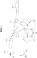
- Figs. 1 and 2 are schematic views (Y-Z sectional views) of a virtual image display device 100 according to a first exemplary embodiment of the present invention.
- the virtual image display device 100 includes a display means (display unit) 101 that displays an image, a virtual image optical system 105 that forms a first virtual image 113 and a second virtual image 116 of the image displayed on a display surface of the display means 101, and a driving means (switching means) 106.
- Figs. 1 and 2 are schematic views (Y-Z sectional
- FIG. 1 and 2 illustrate only an optical path (reference axis) of a principal ray (reference light beam) in a light flux from the display means 101 that passes through the center of a pupil on a reduction side (object side) of the virtual image optical system 105 and reaches the center of a pupil (eye box) on an enlargement side (image side).
- the principal ray does not in fact reach the position of each of the virtual images, but Figs. 1 and 2 also illustrate an optical path of an imaginary principal ray reaching the center of each of the virtual images visually recognized by a user.
- the virtual image display device 100 forms the first virtual image 113 and the second virtual image 116 of the image displayed on the display means 101, thereby enabling the user to recognize as if the formed image is displayed in front of a windshield WS. This makes it possible to, for example, superimpose the image on a surrounding environment (external environment) in front of the windshield WS.
- a display element such as a liquid crystal panel
- a liquid crystal display LCD
- LCOS liquid crystal on silicon
- DMD digital mirror device
- a screen that displays an image projected by a projection means may be adopted.
- the display surface of the display means 101 corresponds to an object plane (reduction plane) of the virtual image optical system 105.
- the present exemplary embodiment assumes a case where the display means 101 is composed of a single display element, but instead the display means 101 may be composed of a plurality of display elements. For example, first and second display elements corresponding to the first virtual image 113 and the second virtual image 116, respectively, may be provided.
- the windshield WS is an optical member provided on a movable body (movable apparatus), such as an automobile (vehicle), on which the virtual image display device 100 is mounted.
- the windshield WS reflects light from the virtual image display device 100 toward an eye 104 of the user (occupant of the movable apparatus), and transmits light from an outside world toward the user.
- a transmissive/reflective surface of the windshield WS may be a flat surface or a curved surface as long as the transmissive/reflective surface has a shape that matches the shape of the movable apparatus.
- a combiner (half mirror) that is a member different from the windshield WS may be adopted as an optical member having the same function as the windshield WS.
- the virtual image display device 100 may directly guide light to the user's eye 104, not via the windshield WS, as needed.
- the virtual image optical system 105 includes first and second optical elements that guide light from the display means 101.
- a refractive element including a refractive surface, or a reflective element including a reflective surface can be adopted.
- the virtual image optical system 105 according to the present exemplary embodiment is composed of a first reflective element 102 (first reflective surface) serving as the first optical element, and a second reflective element 103 (second reflective surface) serving as the second optical element.
- a mirror, a prism, or the like can be adopted as each refractive element.
- An aspheric surface such as a free-form surface, may also be used, as needed.
- each reflective element has a single reflective surface formed thereon
- a reflective element having a plurality of reflective surfaces formed thereon may be adopted.
- the first reflective element 102 and the second reflective element 103 may be integrated into a single reflective element.
- the virtual image optical system 105 may include an optical member, for example, a refractive element or a reflective/refractive element, such as a lens or a prism, or a plate glass (cover glass), as needed.
- the virtual image optical system 105 may desirably have a positive power in an entire system to form each virtual image, and may have a nonpower or negative power reflective surface. If there is an optical path where a virtual image is formed by only one reflective surface (second reflective element 103) as in the present exemplary embodiment, at least the reflective surface needs to have a positive power. However, this is not the case if the windshield WS has a positive power.
- the virtual image optical system 105 by using the first reflective element 102 and the second reflective element 103, guides the light from the display means 101 to a first pupil 112, thereby forming the first virtual image 113.
- the virtual image optical system 105 by using the second reflective element 103, guides the light from the display means 101 to a second pupil 115 without using the first reflective element 102, thereby forming the second virtual image 116.
- the virtual image optical system 105 can simultaneously form a plurality of virtual images of the image displayed on the display means 101.
- the second reflective element 103 is provided to be capable of being decentered (tilted or shifted).
- tilt refers to change of an angle formed between a reference axis (optical axis) and a normal line to the reflective surface of the second reflective element 103 at an intersection with the reference axis (a tilt of the normal line to the reflective surface of the second reflective element 103).
- shifting refers to change of the position of the second reflective element 103. Decentering the second reflective element 103 makes it possible to change an incident angle and a reflection angle of the light from the display means 101 with respect to the reflective surface of the second reflective element 103. However, in the case of shifting the second reflective element 103, only a light reflection position may be changed so as to prevent the incident angle and the reflection angle of the light with respect to the second reflective element 103 from being changed.
- the decentering of the second reflective element 103 that contributes to formation of both the first virtual image 113 and the second virtual image 116 allows positions of the first pupil 112 and the second pupil 115 to be simultaneously changed in a direction including a component of a direction perpendicular to the optical axis. Accordingly, the decentering of the second reflective element 103 makes it possible to switch the positions of the first pupil 112 and the second pupil 115 with each other and to switch an object to be virtually recognized by the user between the first virtual image 113 and the second virtual image 116. Also, in a case where the second optical element is a refractive element, decentering of the refractive element makes it possible to switch the positions of the first pupil 112 and the second pupil 115 to each other.
- Fig. 1 illustrates a first state where the virtual image display device 100 causes the user to visually recognize the first virtual image 113.
- the light from the display means 101 is guided to the enlargement side by the first reflective element 102 and the second reflective element 103 and reaches the user's eye 104 via the windshield WS.
- the tilt and position of the second reflective element 103 are set such that the position of the first pupil 112 corresponds to the position of the user's eye 104.
- the user cannot visually recognize the second virtual image 116.
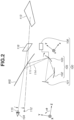
- Fig. 2 illustrates a second state where the virtual image display device 100 causes the user to visually recognize the second virtual image 116.
- the light from the display means 101 is guided to the enlargement side by the second reflective element 103 without using the first reflective element 102, and reaches the user's eye 104 via the windshield WS.
- the tilt and position of the second reflective element 103 are set such that the position of the second pupil 115 corresponds to the position of the user's eye 104.
- the user cannot visually recognize the first virtual image 113.
- the virtual image optical system 105 can simultaneously form the first virtual image 113 and the second virtual image 116 based on the light from the display means 101, and can switch the positions of the first virtual image 113 and the second virtual image 116 to each other by decentering the second reflective element 103.
- the position of a virtual image to be displayed can be switched with the change in the user's viewpoint, without increasing the size of the second reflective element 103. Consequently, it is possible to achieve excellent visibility while simplifying the virtual image optical system 105.
- the driving means 106 causes the second reflective element 103 to be decentered.
- the driving means 106 for example, an actuator such as a motor, and an operation means that non-electrically decenters the second reflective element 103 by a user operation can be adopted.
- the driving means 106 causes the second reflective element 103 to be decentered based on a signal (information) from an external control means, thereby making it possible to switch between the first state and the second state as described above.
- the driving means 106 may also function as a control means.
- the driving means 106 may include a processor, such as a central processing unit (CPU). This configuration enables the driving means 106 to control decentering of the second reflective element 103.
- CPU central processing unit
- the display surface of the display means 101 is perpendicular to a first reference axis (first optical axis) 111 in the first state.
- the display surface may be non-perpendicular to the first reference axis 111, as needed.
- the display surface may be tilted so as to prevent, if light from the outside world, such as sunlight, is incident on the display surface, the light from being regularly reflected by the display surface and from reaching the user's eye 104.
- the display surface of the display means 101 and the second reflective element 103 are disposed so as to oppose each other. This configuration allows the light from the display means 101 to be directly incident on the second reflective element 103 (without using another reflective surface) during formation of the second virtual image 116, thereby making it possible to further simplify the virtual image optical system 105.
- the distance from the first pupil 112 to the first virtual image 113 is longer than the distance from the second pupil 115 to the second virtual image 116. Accordingly, in a case where the user's line of sight is directed toward an object near the user (e.g., a vehicle ahead), for example, when the movable apparatus stops (when the vehicle stops), the second state may be desirably set, and in a case where the user's line of sight is directed toward an object away from the user (a traffic light, a sign, etc.), the first state may be desirably set.
- This configuration makes it possible to reduce the distance between the outside world visually recognized by the user and a virtual image, thereby reducing the user's load of changing the user's line of sight.
- the virtual image optical system 105 is configured to decenter the first virtual image 113 with respect to the first reference axis (first optical axis) 111 that passes through the center of the first virtual image 113, i.e., a straight line connecting the center of the first pupil 112 and the center of the first virtual image 113.
- the shape, tilt, and position of the first reflective element 102 are designed so that the first virtual image 113 is non-perpendicular to the first reference axis 111.
- the virtual image optical system 105 is configured so that the second virtual image 116 is perpendicular to a second reference axis (second optical axis) 114 that passes through the center of the second virtual image 116, i.e., a straight light connecting the center of the second pupil 115 and the center of the second virtual image 116.
- second reference axis second optical axis
- the first virtual image 113 may be perpendicular to the first reference axis 111, or the second virtual image 116 may be non-perpendicular to the second reference axis 114, as needed.
- the first reflective element 102 is located on the lower side (-Y side) of the second reflective element 103 in a direction perpendicular to the first reference axis 111 that passes through the center of the first virtual image 113.
- the lower side relative to the user corresponds to the lower side in the vertical direction, except in particular circumstances where the virtual image display device 100 and the user are upside down (the movable apparatus is upside down).
- the orientation of the first reflective element 102 can be set to match a decentering direction, thus it is easy to correct aberration in the first virtual image 113.
- the virtual image optical system 105 is located on the upper side (+Y-side) of the user, as in a second exemplary example to be described below.
- Image information to be displayed on the display means 101 may be different between the first state and the second state.
- the shape and position of an image can be changed when the first and second states are switched from one to the other, so as to prevent the occurrence of a distortion or a shift of the center position of the image caused by the switching. This can reduce an uncomfortable feeling given to the user when the first and second states are switched from one to the other.
- the user in the first state may not be the same user as the user in the second state.
- the first state and the second state may be switched by decentering the second reflective element 103 upon change of the user. If the relative position between the user's eye 104 and the pupil on the enlargement side of the virtual image optical system 105 is shifted due to change of the user, change of the user's posture, vibrations of the movable apparatus, or the like, the second reflective element 103 may be decentered so as to correct the shift.
- the driving means 106 may cause the second reflective element 103 to be decentered to thereby adjust at least one of the relative position between the first pupil 112 and the user's eye 104 and the relative position between the second pupil 115 and the user's eye 104.
- the driving means 106 may function not only as the switching means, but also as an adjustment means.
- Fig. 3 is a view illustrating a method for adjusting the relative position between the first pupil 112 and the user's eye 104 in the first state.
- the user's eye 104 is located at a position 104a, if the first pupil 112 is located at a position 112a corresponding to the position 104a, the user can visually recognize the first virtual image 113.
- the user's eye 104 is shifted in a direction including a component of a direction perpendicular to a first reference axis 114a (Y-direction) and is located at a position 104b, if the first pupil 112 remains at the position 112a, the user cannot visually recognize the first virtual image 113.
- the driving means 106 causes the second reflective element 103 to be decentered to move the first pupil 112 to a position 112b, which is the position corresponding to the position 104b of the user's eye 104.
- the adjustment of the relative position between the first pupil 112 and the user's eye 104 by decentering the second reflective element 103 enables the user to visually recognize the first virtual image 113 even when the position of the user's eye 104 is changed.
- the adjustment of the relative position between the second pupil 115 and the user's eye 104 by decentering the second reflective element 103 enables the user to visually recognize the second virtual image 116.
- both the switching of the positions of the first pupil 112 and the second pupil 115, and the adjustment of the relative position between each of the first pupil 112 and the second pupil 115 and the user's eye 104 can be performed by the second reflective element 103, which is a single (common) member.
- This configuration eliminates the need for separately providing the means of switching the pupils and the means of adjusting the position of each pupil. Consequently, it is possible to achieve excellent visibility while reducing the number of components constituting the virtual image optical device 100 and simplifying the entire apparatus.
- the number of reflective surfaces located on a first optical path corresponding to the first pupil 112 may be desirably different from the number of reflective surfaces located on a second optical path corresponding to the second pupil 115.
- the first reflective element 102 and the second reflective element 103 are located on the first optical path, and only the second reflective element 103 is located on the second optical path.
- the second reflective element 103 contributes to formation of both the first virtual image 113 and the second virtual image 116, while the first reflective element 102 contributes to formation of only the first virtual image 113.
- the use of the common reflective surface (second reflective element 103) to be decentered on the first and second optical paths makes it possible to reduce the number of components, while the reflective surface located only on one of the optical paths (first reflective element 102) makes it possible to appropriately form the virtual images.
- the virtual images with different positions, shapes, and the like can be formed by, for example, making the first virtual image 113 located farther from the user to be non-perpendicular to the first reference axis 111 and making the second virtual image 116 located closer to the user to be perpendicular to the second reference axis 114.
- the number of reflective surfaces to be located on the first optical path may be the same as the number of reflective surfaces to be located on the second optical paths, as needed.
- another reflective surface may be provided between the display means 101 and the second reflective element 103 on the second optical path.
- one of the optical paths may be desirably provided with only a mirror to be decentered, and the other optical path may be desirably provided with a plurality of mirrors including the mirror to be decentered.
- the virtual image optical system 105 may be desirably composed of two reflective surfaces.
- the virtual image optical system 105 may desirably have a configuration in which two reflective surfaces are located on one of the optical paths and one reflective surface is located on the other optical path.
- Figs. 4A and 4B are schematic views each illustrating a first modification of the virtual image display device 100 according to the present embodiment.
- Fig. 4A illustrates the first state where the position of the user's eye 104 matches the position of the first pupil 112.
- Fig. 4B illustrates the second state where the position of the user's eye 104 matches the position of the second pupil 115.
- the first modification has a configuration in which the second reflective element 103 functions as the windshield WS.
- the second reflective element 103 is configured to transmit light from the opposite side of an incident side of light from the display means 101. This configuration can reduce the number of components of the entire apparatus.
- Fig. 5 is a schematic view illustrating a second modification of the virtual image display device 100 according to the present exemplary embodiment.
- a third reflective surface 123 is located on an optical path between the first reflective element 102 and the second reflective element 103.
- the number of reflective surfaces constituting the virtual image optical system 105 is not limited to two. The same effect can be obtained if three or more reflective surfaces are used.
- the virtual image optical system 105 may be composed of a single reflective element (only the second reflective element 103) if the configuration of the display means 101 is devised and the second reflective element 103 is irradiated with a plurality of light beams corresponding to the pupils.
- At least one optical element that guides at least one of the plurality of light beams corresponding to the pupils to the second reflective element 103, in addition to the second reflective element 103.
- the at least one optical element not only the reflective element, such as the first reflective element 102 illustrated in Fig. 1 , but also the refractive element, such as refractive elements (lenses) 121 and 122 illustrated in Fig. 5 , may be used.
- Fig. 6 is a schematic view of a virtual image display device 100 according to a second exemplary embodiment. Descriptions of components in the virtual image display device 100 according to the present exemplary embodiment that are similar to those of the virtual image display device 100 according to the first exemplary embodiment described above are omitted.
- the virtual image optical system 105 is composed of the first reflective element 102 and the second reflective element 102 that reflect light from the display means 101.
- the first reflective element 102 includes a first reflective surface M1 that guides light to the first pupil 112, and a second reflective surface M2 that guides light to the second pupil 115.
- the second reflective element 103 includes a third reflective surface M3 that guides light to each of the first pupil 112 and the second pupil 115.
- the virtual image optical system 105 guides the light from the display means 101 to the first pupil 112 using the first reflective surface M1 and the third reflective surface M3, thereby forming the first virtual image 113.
- the virtual image optical system 105 guides the light from the display means 101 to the second pupil 115 using the second reflective surface M2 and the third reflective surface M3, thereby forming the second virtual image 116.
- the virtual images can be aligned in the same up/down orientation by setting the same number of reflections on each optical path leading to the corresponding pupil. In other words, there is no need to perform processing of turning the image to be displayed on the display means 101 upside down when the user visually recognizes one of the virtual images.
- the first reflective surface M1 is a concave surface and the second reflective surface M2 is a convex surface.
- the front surface of the first reflective element 102 is an aspheric surface having an inflection point.
- the first reflective surface M1 and the second reflective surface M2 are provided on the same reflective element, which leads to a reduction in the number of components of the entire apparatus.
- the reflective surfaces may be provided on different (separate) reflective elements, as needed.
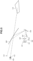
- Fig. 7 is a schematic view of a virtual image display device 100 according to a third exemplary embodiment. Descriptions of components in the virtual image display device 100 according to the present exemplary embodiment that are similar to those of the virtual image display device 100 according to the first exemplary embodiment described above are omitted.
- the virtual image optical system 105 is composed of a refractive element L1 that refracts light from the display means 101, and a reflective element 103 including a reflective surface M1.
- the virtual image optical system 105 guides light from the display means 101 to the first pupil 112 using a lower portion of the refractive element L1 and the reflective surface M1, thereby forming the first virtual image 113.
- the virtual image optical system 105 guides light from the display means 101 to the second pupil 115 using an upper portion of the refractive element L1 and the reflective surface M1, thereby forming the second virtual image 116.
- the use of the refractive element makes it possible to reduce the total length of each optical path.
- the common refractive element L1 is adopted for each optical path in the present exemplary embodiment, a different (separate) refractive element may be disposed on each optical path.
- a plurality of refractive elements may be disposed on one optical path.
- the refractive element is not limited to a positive lens as illustrated in Fig. 7 .
- a negative lens may be disposed, as needed, and the refractive surface (lens surface) may be an aspheric surface such as a free-form surface.
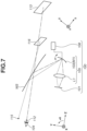
- Fig. 8 is a schematic view of a virtual image display device 100 according to a fourth exemplary embodiment. Descriptions of components in the virtual image display device 100 according to the present exemplary embodiment that are similar to those of the virtual image display device 100 according to the first exemplary embodiment described above are omitted.
- the virtual image optical system 105 is composed of a first reflective element 131 including the first reflective surface M1, which reflects and transmits light from the display means 101, a second reflective element 132 including the second reflective surface M2, and the third reflective element 103 including the third reflective surface M3.
- the virtual image optical system 105 guides light that is output from the display means 101 and is transmitted through the first reflective surface M1 to the first pupil 112 using the second reflective surface M2 and the third reflective surface M3, thereby forming the first virtual image 113.
- the virtual image optical system 105 guides light from the display means 101 to the second pupil 115 using the first reflective surface M1 and the third reflective surface M3, thereby forming the second virtual image 116.
- the adoption of the reflective element (reflective/transmissive element) including the reflective surface (reflective/transmissive surface) that reflects and transmits light makes it possible to secure a difference in optical path length between the optical paths with a smaller space and to achieve miniaturization of the entire apparatus.
- the first reflective element 131 for example, a partially reflective mirror provided with a reflective film formed only on a portion of a translucent member that corresponds to the second pupil 115, a perforated mirror having an opening formed only on a portion corresponding to the first pupil 112, or the like can be adopted.
- a half mirror that reflects a part of incident light and transmits the remaining light a dichroic mirror that reflects light of a specific wavelength and transmits the remaining light, a polarization mirror that reflects light in a specific polarization state and transmits the remaining light, or the like may be adopted.
- a liquid crystal element or electrochromic element that switches between reflecting and transmitting light by being applied with a voltage may be adopted.
- first reflective surface M1 and the second reflective surface M2 are provided on different reflective elements, but instead the first reflective surface M1 and the second reflective surface M2 may be provided on the same reflective element (reflective/transmissive element).
- Fig. 9 is a schematic view of a virtual image display device according to a fifth exemplary embodiment. Descriptions of components in a virtual image display device 100 according to the present exemplary embodiment that are similar to those of the virtual image display device 100 according to the first exemplary embodiment described above are omitted.
- the virtual image optical system 105 is composed of the first reflective element 102 that reflects light from the display means 101 and the second reflective element 102 that reflects and transmits light.
- the first reflective element 102 includes the first reflective surface M1 that guides light to the first pupil 112, and the second reflective surface M2 that guides light to the second pupil 115.
- the second reflective element 103 includes the third reflective surface M3 that guides light to the first pupil 112, and a fourth reflective surface M4 that guides light to the second pupil 115.
- the virtual image optical system 105 guides light from the display means 101 to the first pupil 112 using the first reflective surface M1 and the third reflective surface M3, thereby forming the first virtual image 113.
- the virtual image optical system 105 guides light from the display means 101 to the second pupil 115 using the second reflective surface M2, the third reflective surface M3, and the fourth reflective surface M4, thereby forming the second virtual image 116.
- the second reflective element (reflective/transmissive element) 103 including the third reflective surface M3 as the reflective surface (reflective/transmissive surface) that reflects and transmits light is adopted. This configuration makes it possible to secure the difference in optical path length between the optical paths with a smaller space and to achieve miniaturization of the entire apparatus, similar to the fourth exemplary embodiment.
- the third reflective surface M3 can be configured in the same manner as the first reflective surface M1 of the fourth exemplary embodiment.
- the third reflective surface M3 and the fourth reflective surface M4 are provided on the same reflective element, but instead the third reflective surface M3 and the fourth reflective surface M4 may be provided on different reflective elements, as needed.
- the positions of the first pupil 112 and the second pupil 115 are switched by shifting the second reflective element 103, instead of tilting the second reflective element 103.
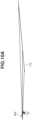
- Figs. 10A and 10B and Figs. 11A and 11B are schematic views of a major part of a virtual image display device 10 according to a first numerical example.
- Fig. 10A illustrates an optical path for light from the virtual image display device 10 in the first state to reach the first pupil 112 via the windshield WS, and an imaginary optical path when light from the virtual image display device 10 forms the first virtual image 113.
- Fig. 10B is an enlarged view of the optical path from the virtual image display device 10 illustrated in Fig. 10A to the first pupil 112.
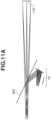
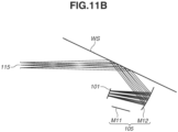
- FIG. 11A illustrates an optical path for light from the virtual image display device 10 in the second state to reach the second pupil 115 via the windshield WS, and an imaginary optical path when the light from the virtual image display device 10 forms the second virtual image 116.
- Fig. 11B is an enlarged view of the optical path from the virtual image display device 10 illustrated in Fig. 11A to the second pupil 115.
- the virtual image optical system 105 is composed of a first reflective element (first mirror) M11 including the first reflective element 102, and a second reflective element (second mirror) M12 including the second reflective element 103.
- the virtual image display device 10 according to the present numerical example decenters the second reflective element M12, thereby making it possible to switch the positions of the first pupil 112 and the second pupil 115 to each other.
- Figs. 12 and 13 are schematic views of a major part of a virtual image display device 20 according to a second numerical example.
- Fig. 12 illustrates an optical path for light from the virtual image display device 20 in the first state to reach the first pupil 112 via the windshield WS.
- Fig. 13 illustrates an optical path for light from the virtual image display device 20 in the second state to reach the second pupil 115 via the windshield WS.
- the virtual image optical system 105 is composed of a first reflective element (first mirror) M21 including the first reflective element 102, and a second reflective element (second mirror) M22 including the second reflective element 103.
- the virtual image display device 20 according to the present numerical example decenters the second reflective element M22, thereby making it possible to switch the positions of the first pupil 112 and the second pupil 115 to each other.
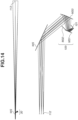
- Figs. 14 and 15 are schematic views of a major part of a virtual image display device 30 according to a third numerical example.
- Fig. 14(a) illustrates an optical path for light from the virtual image display device 30 in the first state to reach the first pupil 112 via the windshield WS, and an imaginary optical path when the light from the virtual image display device 30 forms the first virtual image 113.
- Fig. 14(b) is an enlarged view of the optical path from the virtual image display device 30 illustrated in Fig. 14(a) to the first pupil 112.
- Fig. 15(a) illustrates an optical path for light from the virtual image display device 30 in the second state to reach the second pupil 115 via the windshield WS, and an imaginary optical path when the light from the virtual image display device 30 forms the second virtual image 116.
- Fig. 15(b) is an enlarged view of the optical path from the virtual image display device 30 illustrated in Fig. 15(a) to the second pupil 115.
- the virtual image optical system 105 is composed of a first reflective element (first mirror) M31 including the first reflective surface, a second reflective element (second mirror) M32 including the second reflective surface, and a third refractive element (third mirror) M33 including the third reflective surface.
- the virtual image display device 30 according to the present numerical example decenters the third refractive element M33, thereby making it possible to switch the positions of the first pupil 112 and the second pupil 115 to each other.
- Figs. 16 and 17 are schematic views of a major part of a virtual image display device 40 according to a fourth numerical example.
- Fig. 16 illustrates an optical path for light from the virtual image display device 40 in the first state to reach the first pupil 112 via the windshield WS.
- Fig. 17 illustrates an optical path for light from the virtual image display device 40 in the second state to reach the second pupil 115 via the windshield WS.
- the virtual image optical system 105 is composed of a first reflective element (first mirror) M41 including the first reflective surface, a second reflective element (second mirror) M42 including the reflective/transmissive surface, and a third refractive element (third mirror) M43 including the third reflective surface.
- first reflective element first mirror
- second reflective element second mirror
- third refractive element third mirror
- the light corresponding to the first pupil 112 is transmitted through the second reflective element M42 and is reflected by the first reflective element M41, and is then transmitted through the second reflective element M42 again and is directed toward the third refractive element M43.
- the virtual image display device 40 according to the present numerical example decenters the third refractive element M43, thereby making it possible to switch the positions of the first pupil 112 and the second pupil 115 to each other.
- the virtual image optical system 105 according to the first and second numerical examples switches the positions of the pupils by decentering the reflective element, but instead may switch the positions of the pupils by decentering the refractive element as described above.
- the virtual image optical system 105 is an off-axial optical system.
- the optical axis (reference axis) of the virtual image optical system 105 is different between the first state and the second state.
- an absolute coordinate system XYZ with the center of each of the first and second pupils as an origin is defined to represent the position and eccentric angle of each surface.
- the normal line at the origin is defined as a Z-axis and the direction from the object plane to the image side is defined as a positive direction (+Z-direction).
- An axis that passes through the origin and forms 90° in a counterclockwise direction with respect to the Z-axis according to the definition of a right-handed coordinate system is defined as a Y-axis.
- An axis that passes through the origin and is perpendicular to each of the Z-axis and the Y-axis is defined as an X-axis, and a direction toward the back with respect to the paper surface of each drawing is defined as a positive direction (+X-direction).
- Y and Z [mm] represent coordinates in the Y-direction and the Z-direction, respectively, of a surface vertex of each surface in the absolute coordinate system
- ⁇ [degrees] represents an inclination (eccentric angle) of the normal line at the surface vertex of each surface when a direction of counterclockwise rotation relative to the X-axis is positive.
- a local coordinate system xyz with an intersection between each surface and the Z-axis (reference axis) as an origin is defined to represent the shape of each surface.
- the normal line at the origin is defined as a z-axis.
- An axis that passes through the origin and forms 90° in the counterclockwise direction with respect to the z-axis according to the definition of the right-handed coordinate system is defined as a y-axis.
- An axis that passes through the origin and is perpendicular to each of the z-axis and the y-axis is defined as an x-axis, and a direction toward the back with respect to the paper surface of Fig. 1 is defined as a positive direction (+x-direction).
- an aspheric surface is expressed by the following formula where a conic constant is represented by K, an aspheric surface coefficient is represented by C ij , and a paraxial curvature radius is represented by R.
- K conic constant
- C ij an aspheric surface coefficient
- R paraxial curvature radius
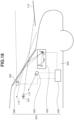
- Fig. 18 is a schematic view of an on-vehicle system 500 including the virtual image display device 100 and a movable apparatus 600 according to the present exemplary embodiment.
- the on-vehicle system 500 is a system that includes the virtual image display device 100, a first obtaining means 200, a second obtaining means 300, and a control means 400, and assists a user (occupant, driver) of the movable apparatus 600.
- the movable apparatus 600 is a movable body, such as an automobile, a ship, or an aircraft, which can move while holding the on-vehicle system 500 described above.
- Fig. 18 illustrates an automobile (vehicle) as an example of the movable apparatus 600.
- the first obtaining means 200 is a means of obtaining at least one of positional information and viewpoint information about the user and is, for example, an imaging device such as a camera.
- the positional information about the user is information about a position of at least a part of the user and is, for example, information about the position of the user's eye 104.
- the viewpoint information about the user is information about a viewpoint or line of sight of the user and is, for example, information about a motion of the user's eye 104 (pupil).
- the second obtaining means 300 is a means of obtaining information about the outside world (surrounding information) including obstacles (pedestrians, other vehicles, etc.) around the movable apparatus 600, a surrounding environment (landscape), and the like, and is, for example, an imaging device such as a camera.
- the second obtaining means 300 according to the present exemplary embodiment is disposed to obtain information about the outside world in front of the movable apparatus 600, but instead may be disposed to obtain information about the outside world on the rear side, the lateral side, or the like of the movable apparatus 600.
- the control means 400 is a means of controlling the virtual image display device 100 and is, for example, a processor such as a CPU.
- the control means 400 can control display of an image by the display means 101 in the virtual image display device 100, and control decentering of the reflective surface by the driving means 106.
- the control means 400 can control the display of an image by the display means 101 and the decentering of the reflective surface by the driving means 106 based on at least one of information obtained by the first obtaining means 200 and information obtained by the second obtaining means 300.
- the control means 400 may be provided in the virtual image display device 100.
- the first obtaining means 200 obtains at least one of the positional information and the viewpoint information about the user, thereby making it possible to detect a shift amount of the position of the user's eye 104 relative to the movable apparatus 600.
- the control means 400 obtains a driving amount (decentering amount) of the second reflective element 103 in the virtual image display device 100 based on the information obtained by the first obtaining means 200, and controls the driving means 106 based on the driving amount to thereby decenter the second reflective element 103. This makes it possible to correct a shift in the relative position between the user's eye 104 and the pupil of the virtual image display device 100.
- control means 400 may switch between virtual images to be visually recognized by the user by controlling decentering of the second reflective element 103 based on information (speed information) about a moving speed of the movable apparatus 600.
- the display of the first virtual image 113 seen at a far distance and the display of the second virtual image 116 seen at a near distance are switched so as to allow the user to visually recognize as if the position of the virtual image in a traveling direction of the movable apparatus 600 has been switched. For example, when the movable apparatus 600 is moving at a first speed, the first virtual image 113 may be displayed, and when the movable apparatus 600 is moving at a second speed higher than the first speed, the second virtual image 116 may be displayed.
- the first virtual image 113 is displayed when the movable apparatus 600 is moving at a low speed or stops (at a speed of 0), and the second virtual image 116 is displayed when the movable apparatus 600 is moving at a high speed, thereby it is possible to satisfactorily superimpose each virtual image on the outside world. Consequently, the visibility of each virtual image when the speed of the movable apparatus 600 has changed can be improved.
- the user may operate the operation means (not illustrated) to allow the control means 400 to control decentering of the second reflective element 103 by the driving means 106 based on a signal output from the operation means. Even in a case where the first obtaining means 200 obtains information about a position other than the user's eye 104, the control means 400 can obtain the shift amount of the position of the user's eye 104 with respect to the movable apparatus 600 based on the information.
- the control means 400 also has a function as a determination means of determining a possibility of collision with an obstacle (object). For example, the control means 400 determines the possibility of collision between the movable apparatus 600 and an obstacle based on the information about the outside world obtained by the second obtaining means 300. If the control means 400 determines that there is the possibility of collision with an obstacle, for example, a warning can be issued to the user by displaying a warning message or the like on the virtual image display device 100.
- the control means 400 may control a movement of the movable apparatus 600, or may issue a warning to each unit of the movable apparatus 600.
- the control means 400 can control the movement of the movable apparatus 600 by outputting a control signal to a driving unit (an engine, a motor, or the like) of the movable apparatus 600.
- a control method include applying a brake, releasing an accelerator, turning a steering wheel, and suppressing an output from the driving unit by generating a control signal for generating a braking force on each wheel in the movable apparatus 600.
- Examples of a warning method include issuing an alarm to the user, displaying warning information on a screen of a car navigation system or the like, and applying a vibration to a seat belt or a steering wheel.
- the on-vehicle system 500 includes a single first obtaining means 200 and a single second obtaining means 300, but instead may include a plurality of first obtaining means 200 and a plurality of second obtaining means 300.
- a single obtaining means having both of the functions of the first obtaining means 200 and the second obtaining means 300 may be adopted.
- a means that detects a vibration, an acceleration, or the like of the movable apparatus 600 may be provided to control the virtual image display device 100 based on information obtained by the means.
Landscapes
- Physics & Mathematics (AREA)
- Engineering & Computer Science (AREA)
- General Physics & Mathematics (AREA)
- Optics & Photonics (AREA)
- Chemical & Material Sciences (AREA)
- Combustion & Propulsion (AREA)
- Transportation (AREA)
- Mechanical Engineering (AREA)
- Lenses (AREA)
Applications Claiming Priority (2)
| Application Number | Priority Date | Filing Date | Title |
|---|---|---|---|
| JP2021050220 | 2021-03-24 | ||
| PCT/JP2022/010502 WO2022202352A1 (fr) | 2021-03-24 | 2022-03-10 | Système optique d'image virtuelle, dispositif d'affichage d'image virtuelle équipé de celui-ci, et système monté sur véhicule |
Publications (1)
| Publication Number | Publication Date |
|---|---|
| EP4318077A1 true EP4318077A1 (fr) | 2024-02-07 |
Family
ID=83395661
Family Applications (1)
| Application Number | Title | Priority Date | Filing Date |
|---|---|---|---|
| EP22775144.3A Pending EP4318077A1 (fr) | 2021-03-24 | 2022-03-10 | Système optique d'image virtuelle, dispositif d'affichage d'image virtuelle équipé de celui-ci, et système monté sur véhicule |
Country Status (5)
| Country | Link |
|---|---|
| US (1) | US20240118544A1 (fr) |
| EP (1) | EP4318077A1 (fr) |
| JP (1) | JPWO2022202352A1 (fr) |
| CN (1) | CN117043661A (fr) |
| WO (1) | WO2022202352A1 (fr) |
Families Citing this family (1)
| Publication number | Priority date | Publication date | Assignee | Title |
|---|---|---|---|---|
| JP2024080786A (ja) * | 2022-12-05 | 2024-06-17 | キヤノン株式会社 | 情報処理装置、表示システム、移動体、情報処理方法、及びコンピュータプログラム |
Family Cites Families (6)
| Publication number | Priority date | Publication date | Assignee | Title |
|---|---|---|---|---|
| US20180112180A1 (en) | 2015-01-26 | 2018-04-26 | Fate Therapeutics, Inc. | Cells with increased immuno-regulatory properties and methods for their use and manufacture |
| JP6604910B2 (ja) * | 2016-06-20 | 2019-11-13 | アルプスアルパイン株式会社 | 画像表示装置およびヘッドアップディスプレイ装置 |
| KR101899981B1 (ko) * | 2016-12-02 | 2018-09-19 | 엘지전자 주식회사 | 차량용 헤드 업 디스플레이 |
| JP6839806B2 (ja) * | 2017-09-21 | 2021-03-10 | パナソニックIpマネジメント株式会社 | ヘッドアップディスプレイ装置、及び車両 |
| CN108919494B (zh) * | 2018-08-01 | 2021-02-02 | 张家港康得新光电材料有限公司 | 一种抬头显示装置及汽车 |
| JP7110968B2 (ja) | 2018-12-17 | 2022-08-02 | 株式会社デンソー | ヘッドアップディスプレイ装置 |
-
2022
- 2022-03-10 JP JP2023508980A patent/JPWO2022202352A1/ja active Pending
- 2022-03-10 CN CN202280023586.6A patent/CN117043661A/zh active Pending
- 2022-03-10 EP EP22775144.3A patent/EP4318077A1/fr active Pending
- 2022-03-10 WO PCT/JP2022/010502 patent/WO2022202352A1/fr active Application Filing
-
2023
- 2023-09-21 US US18/472,120 patent/US20240118544A1/en active Pending
Also Published As
| Publication number | Publication date |
|---|---|
| CN117043661A (zh) | 2023-11-10 |
| WO2022202352A1 (fr) | 2022-09-29 |
| US20240118544A1 (en) | 2024-04-11 |
| JPWO2022202352A1 (fr) | 2022-09-29 |
Similar Documents
| Publication | Publication Date | Title |
|---|---|---|
| US8319762B2 (en) | Scanning image display apparatus, goggle-shaped head-mounted display, and automobile | |
| US7298557B2 (en) | Projection unit for a head-up display | |
| JPH0472734B2 (fr) | ||
| US20060232853A1 (en) | Projection unit for a head-up display | |
| KR101572132B1 (ko) | 시도 조절이 가능한 전방 상향 시현용 광학계 | |
| JP7162273B2 (ja) | ヘッドアップディスプレイおよびヘッドアップディスプレイを搭載した移動体 | |
| JPH08197981A (ja) | 車輌用表示装置 | |
| JP6648818B2 (ja) | スクリーン及びヘッドアップディスプレイ装置 | |
| US20190369395A1 (en) | Virtual image display device | |
| US20240118544A1 (en) | Virtual image optical system, and virtual image display device and on-vehicle system including virtual image optical system | |
| JP2024137999A (ja) | ヘッドアップディスプレイ | |
| WO2019116731A1 (fr) | Affichage tête haute et corps mobile avec un affichage tête haute monté dessus | |
| US7671822B2 (en) | Optical unit for a head-up display | |
| CN114764195A (zh) | 一种hud系统及车辆 | |
| WO2018186149A1 (fr) | Système d'affichage tête haute, et objet mobile équipé du système d'affichage tête haute | |
| JP2760767B2 (ja) | 円環状結合器を使用する軸外れヘッドアップディスプレイシステム | |
| CN113970845B (zh) | 多焦平面抬头显示设备 | |
| US20230152510A1 (en) | Virtual image optical system, virtual image display device, and on-board system, latter two including virtual image optical system | |
| WO2021065592A1 (fr) | Dispositif d'affichage d'image virtuelle, système monté sur véhicule équipé de celui-ci, et appareil mobile | |
| JP7372618B2 (ja) | 車載表示装置 | |
| EP3534202B1 (fr) | Dispositif d'affichage d'image virtuelle | |
| CN217484609U (zh) | 抬头显示装置以及载运工具 | |
| JP2023079736A (ja) | 虚像表示装置、それを備える車載システム及び移動装置 | |
| JP2021060444A (ja) | 虚像表示装置、それを備える車載システム及び移動装置 | |
| JP2021060445A (ja) | 虚像表示装置、それを備える車載システム及び移動装置 |
Legal Events
| Date | Code | Title | Description |
|---|---|---|---|
| STAA | Information on the status of an ep patent application or granted ep patent |
Free format text: STATUS: THE INTERNATIONAL PUBLICATION HAS BEEN MADE |
|
| PUAI | Public reference made under article 153(3) epc to a published international application that has entered the european phase |
Free format text: ORIGINAL CODE: 0009012 |
|
| STAA | Information on the status of an ep patent application or granted ep patent |
Free format text: STATUS: REQUEST FOR EXAMINATION WAS MADE |
|
| 17P | Request for examination filed |
Effective date: 20231024 |
|
| AK | Designated contracting states |
Kind code of ref document: A1 Designated state(s): AL AT BE BG CH CY CZ DE DK EE ES FI FR GB GR HR HU IE IS IT LI LT LU LV MC MK MT NL NO PL PT RO RS SE SI SK SM TR |
|
| DAV | Request for validation of the european patent (deleted) | ||
| DAX | Request for extension of the european patent (deleted) |