EP4317860A1 - Accumulator heat exchanger - Google Patents
Accumulator heat exchanger Download PDFInfo
- Publication number
- EP4317860A1 EP4317860A1 EP22189140.1A EP22189140A EP4317860A1 EP 4317860 A1 EP4317860 A1 EP 4317860A1 EP 22189140 A EP22189140 A EP 22189140A EP 4317860 A1 EP4317860 A1 EP 4317860A1
- Authority
- EP
- European Patent Office
- Prior art keywords
- inlet conduit
- heat exchange
- accumulator
- refrigerant
- exchange coil
- Prior art date
- Legal status (The legal status is an assumption and is not a legal conclusion. Google has not performed a legal analysis and makes no representation as to the accuracy of the status listed.)
- Pending
Links
Images



Classifications
-
- F—MECHANICAL ENGINEERING; LIGHTING; HEATING; WEAPONS; BLASTING
- F25—REFRIGERATION OR COOLING; COMBINED HEATING AND REFRIGERATION SYSTEMS; HEAT PUMP SYSTEMS; MANUFACTURE OR STORAGE OF ICE; LIQUEFACTION SOLIDIFICATION OF GASES
- F25B—REFRIGERATION MACHINES, PLANTS OR SYSTEMS; COMBINED HEATING AND REFRIGERATION SYSTEMS; HEAT PUMP SYSTEMS
- F25B43/00—Arrangements for separating or purifying gases or liquids; Arrangements for vaporising the residuum of liquid refrigerant, e.g. by heat
- F25B43/006—Accumulators
-
- F—MECHANICAL ENGINEERING; LIGHTING; HEATING; WEAPONS; BLASTING
- F28—HEAT EXCHANGE IN GENERAL
- F28D—HEAT-EXCHANGE APPARATUS, NOT PROVIDED FOR IN ANOTHER SUBCLASS, IN WHICH THE HEAT-EXCHANGE MEDIA DO NOT COME INTO DIRECT CONTACT
- F28D20/00—Heat storage plants or apparatus in general; Regenerative heat-exchange apparatus not covered by groups F28D17/00 or F28D19/00
- F28D20/0034—Heat storage plants or apparatus in general; Regenerative heat-exchange apparatus not covered by groups F28D17/00 or F28D19/00 using liquid heat storage material
-
- F—MECHANICAL ENGINEERING; LIGHTING; HEATING; WEAPONS; BLASTING
- F28—HEAT EXCHANGE IN GENERAL
- F28D—HEAT-EXCHANGE APPARATUS, NOT PROVIDED FOR IN ANOTHER SUBCLASS, IN WHICH THE HEAT-EXCHANGE MEDIA DO NOT COME INTO DIRECT CONTACT
- F28D7/00—Heat-exchange apparatus having stationary tubular conduit assemblies for both heat-exchange media, the media being in contact with different sides of a conduit wall
- F28D7/02—Heat-exchange apparatus having stationary tubular conduit assemblies for both heat-exchange media, the media being in contact with different sides of a conduit wall the conduits being helically coiled
-
- F—MECHANICAL ENGINEERING; LIGHTING; HEATING; WEAPONS; BLASTING
- F25—REFRIGERATION OR COOLING; COMBINED HEATING AND REFRIGERATION SYSTEMS; HEAT PUMP SYSTEMS; MANUFACTURE OR STORAGE OF ICE; LIQUEFACTION SOLIDIFICATION OF GASES
- F25B—REFRIGERATION MACHINES, PLANTS OR SYSTEMS; COMBINED HEATING AND REFRIGERATION SYSTEMS; HEAT PUMP SYSTEMS
- F25B40/00—Subcoolers, desuperheaters or superheaters
- F25B40/02—Subcoolers
-
- F—MECHANICAL ENGINEERING; LIGHTING; HEATING; WEAPONS; BLASTING
- F25—REFRIGERATION OR COOLING; COMBINED HEATING AND REFRIGERATION SYSTEMS; HEAT PUMP SYSTEMS; MANUFACTURE OR STORAGE OF ICE; LIQUEFACTION SOLIDIFICATION OF GASES
- F25B—REFRIGERATION MACHINES, PLANTS OR SYSTEMS; COMBINED HEATING AND REFRIGERATION SYSTEMS; HEAT PUMP SYSTEMS
- F25B41/00—Fluid-circulation arrangements
- F25B41/30—Expansion means; Dispositions thereof
- F25B41/31—Expansion valves
-
- F—MECHANICAL ENGINEERING; LIGHTING; HEATING; WEAPONS; BLASTING
- F25—REFRIGERATION OR COOLING; COMBINED HEATING AND REFRIGERATION SYSTEMS; HEAT PUMP SYSTEMS; MANUFACTURE OR STORAGE OF ICE; LIQUEFACTION SOLIDIFICATION OF GASES
- F25B—REFRIGERATION MACHINES, PLANTS OR SYSTEMS; COMBINED HEATING AND REFRIGERATION SYSTEMS; HEAT PUMP SYSTEMS
- F25B41/00—Fluid-circulation arrangements
- F25B41/40—Fluid line arrangements
- F25B41/42—Arrangements for diverging or converging flows, e.g. branch lines or junctions
-
- F—MECHANICAL ENGINEERING; LIGHTING; HEATING; WEAPONS; BLASTING
- F25—REFRIGERATION OR COOLING; COMBINED HEATING AND REFRIGERATION SYSTEMS; HEAT PUMP SYSTEMS; MANUFACTURE OR STORAGE OF ICE; LIQUEFACTION SOLIDIFICATION OF GASES
- F25B—REFRIGERATION MACHINES, PLANTS OR SYSTEMS; COMBINED HEATING AND REFRIGERATION SYSTEMS; HEAT PUMP SYSTEMS
- F25B43/00—Arrangements for separating or purifying gases or liquids; Arrangements for vaporising the residuum of liquid refrigerant, e.g. by heat
-
- F—MECHANICAL ENGINEERING; LIGHTING; HEATING; WEAPONS; BLASTING
- F28—HEAT EXCHANGE IN GENERAL
- F28D—HEAT-EXCHANGE APPARATUS, NOT PROVIDED FOR IN ANOTHER SUBCLASS, IN WHICH THE HEAT-EXCHANGE MEDIA DO NOT COME INTO DIRECT CONTACT
- F28D1/00—Heat-exchange apparatus having stationary conduit assemblies for one heat-exchange medium only, the media being in contact with different sides of the conduit wall, in which the other heat-exchange medium is a large body of fluid, e.g. domestic or motor car radiators
- F28D1/02—Heat-exchange apparatus having stationary conduit assemblies for one heat-exchange medium only, the media being in contact with different sides of the conduit wall, in which the other heat-exchange medium is a large body of fluid, e.g. domestic or motor car radiators with heat-exchange conduits immersed in the body of fluid
- F28D1/04—Heat-exchange apparatus having stationary conduit assemblies for one heat-exchange medium only, the media being in contact with different sides of the conduit wall, in which the other heat-exchange medium is a large body of fluid, e.g. domestic or motor car radiators with heat-exchange conduits immersed in the body of fluid with tubular conduits
- F28D1/047—Heat-exchange apparatus having stationary conduit assemblies for one heat-exchange medium only, the media being in contact with different sides of the conduit wall, in which the other heat-exchange medium is a large body of fluid, e.g. domestic or motor car radiators with heat-exchange conduits immersed in the body of fluid with tubular conduits the conduits being bent, e.g. in a serpentine or zig-zag
- F28D1/0472—Heat-exchange apparatus having stationary conduit assemblies for one heat-exchange medium only, the media being in contact with different sides of the conduit wall, in which the other heat-exchange medium is a large body of fluid, e.g. domestic or motor car radiators with heat-exchange conduits immersed in the body of fluid with tubular conduits the conduits being bent, e.g. in a serpentine or zig-zag the conduits being helically or spirally coiled
-
- F—MECHANICAL ENGINEERING; LIGHTING; HEATING; WEAPONS; BLASTING
- F28—HEAT EXCHANGE IN GENERAL
- F28F—DETAILS OF HEAT-EXCHANGE AND HEAT-TRANSFER APPARATUS, OF GENERAL APPLICATION
- F28F9/00—Casings; Header boxes; Auxiliary supports for elements; Auxiliary members within casings
- F28F9/24—Arrangements for promoting turbulent flow of heat-exchange media, e.g. by plates
-
- F—MECHANICAL ENGINEERING; LIGHTING; HEATING; WEAPONS; BLASTING
- F25—REFRIGERATION OR COOLING; COMBINED HEATING AND REFRIGERATION SYSTEMS; HEAT PUMP SYSTEMS; MANUFACTURE OR STORAGE OF ICE; LIQUEFACTION SOLIDIFICATION OF GASES
- F25B—REFRIGERATION MACHINES, PLANTS OR SYSTEMS; COMBINED HEATING AND REFRIGERATION SYSTEMS; HEAT PUMP SYSTEMS
- F25B2400/00—Component parts or details not otherwise provided for in this subclass
- F25B2400/05—Compression system with heat exchange between particular parts of the system
- F25B2400/051—Compression system with heat exchange between particular parts of the system between the accumulator and another part of the cycle
-
- F—MECHANICAL ENGINEERING; LIGHTING; HEATING; WEAPONS; BLASTING
- F25—REFRIGERATION OR COOLING; COMBINED HEATING AND REFRIGERATION SYSTEMS; HEAT PUMP SYSTEMS; MANUFACTURE OR STORAGE OF ICE; LIQUEFACTION SOLIDIFICATION OF GASES
- F25B—REFRIGERATION MACHINES, PLANTS OR SYSTEMS; COMBINED HEATING AND REFRIGERATION SYSTEMS; HEAT PUMP SYSTEMS
- F25B2500/00—Problems to be solved
- F25B2500/18—Optimization, e.g. high integration of refrigeration components
-
- F—MECHANICAL ENGINEERING; LIGHTING; HEATING; WEAPONS; BLASTING
- F25—REFRIGERATION OR COOLING; COMBINED HEATING AND REFRIGERATION SYSTEMS; HEAT PUMP SYSTEMS; MANUFACTURE OR STORAGE OF ICE; LIQUEFACTION SOLIDIFICATION OF GASES
- F25B—REFRIGERATION MACHINES, PLANTS OR SYSTEMS; COMBINED HEATING AND REFRIGERATION SYSTEMS; HEAT PUMP SYSTEMS
- F25B40/00—Subcoolers, desuperheaters or superheaters
-
- F—MECHANICAL ENGINEERING; LIGHTING; HEATING; WEAPONS; BLASTING
- F28—HEAT EXCHANGE IN GENERAL
- F28D—HEAT-EXCHANGE APPARATUS, NOT PROVIDED FOR IN ANOTHER SUBCLASS, IN WHICH THE HEAT-EXCHANGE MEDIA DO NOT COME INTO DIRECT CONTACT
- F28D20/00—Heat storage plants or apparatus in general; Regenerative heat-exchange apparatus not covered by groups F28D17/00 or F28D19/00
- F28D2020/0065—Details, e.g. particular heat storage tanks, auxiliary members within tanks
- F28D2020/0069—Distributing arrangements; Fluid deflecting means
-
- F—MECHANICAL ENGINEERING; LIGHTING; HEATING; WEAPONS; BLASTING
- F28—HEAT EXCHANGE IN GENERAL
- F28D—HEAT-EXCHANGE APPARATUS, NOT PROVIDED FOR IN ANOTHER SUBCLASS, IN WHICH THE HEAT-EXCHANGE MEDIA DO NOT COME INTO DIRECT CONTACT
- F28D7/00—Heat-exchange apparatus having stationary tubular conduit assemblies for both heat-exchange media, the media being in contact with different sides of a conduit wall
- F28D7/02—Heat-exchange apparatus having stationary tubular conduit assemblies for both heat-exchange media, the media being in contact with different sides of a conduit wall the conduits being helically coiled
- F28D7/024—Heat-exchange apparatus having stationary tubular conduit assemblies for both heat-exchange media, the media being in contact with different sides of a conduit wall the conduits being helically coiled the conduits of only one medium being helically coiled tubes, the coils having a cylindrical configuration
Definitions
- the present disclosure relates to an accumulator heat exchanger and a refrigeration system comprising an accumulator heat exchanger.
- the present disclosure also relates to a method of heat exchange using an accumulator heat exchanger.
- Accumulators are used in refrigeration systems to collect liquid refrigerant and thus prevent liquid refrigerant from passing into the compressor where it can cause damage.
- Heat exchangers are used in refrigeration systems in order to control the temperature of the refrigerant. It is known to provide accumulator heat exchangers which combine the functions of accumulators and heat exchangers. Accumulator heat exchangers can reduce the temperature of a first refrigerant flow before the refrigerant enters an evaporator in order to increase its cooling capacity, and simultaneously increase the temperature of a second refrigerant flow before the refrigerant enters a compressor in order to promote the formation of gaseous refrigerant from liquid refrigerant.
- Heat can hence be extracted from the first refrigerant flow to form subcooled refrigerant used within a first portion of the refrigeration system, and that heat can be usefully used for heating the second refrigerant flow to form superheated refrigerant used within a second portion of the refrigeration system.
- an accumulator heat exchanger for use within a refrigeration system, the accumulator heat exchanger comprising: an accumulator vessel with an internal volume for accumulation of refrigerant fluid; a heat exchange coil disposed within the internal volume of the accumulator vessel wherein the heat exchange coil encloses an axially extending inner volume of the heat exchange coil; a first inlet conduit for introducing refrigerant fluid into the internal volume, the first inlet conduit extending from outside of the accumulator vessel to an inner end of the first inlet conduit within the internal volume of the accumulator vessel, and a first outlet conduit for exhausting superheated gaseous refrigerant from the internal volume, the first outlet conduit extending from within the internal volume of the accumulator vessel to outside of the accumulator vessel; and a second inlet conduit for subcooled refrigerant fluid and a second outlet conduit for subcooled refrigerant fluid, wherein the second inlet conduit and second outlet conduit provide an inlet and outlet flow path for the heat exchange coil;
- refrigerant fluid entering the accumulator vessel via the first inlet conduit may comprise gaseous refrigerant, liquid refrigerant or a mixture of these.
- the accumulator vessel may have an axial extent and a radial extent.
- the accumulator vessel may be cylindrical, the axial and radial extent of the accumulator vessel following the axial and radial dimensions of the cylinder respectively.
- the heat exchange coil, and the axially extending inner volume defined thereby may have an axial extent and an extent perpendicular to the axial extent, for example a radial extent.
- the heat exchange coil and the inner volume defined thereby may therefore comprise an axial direction and a direction perpendicular to the axial direction, for example a radial direction.
- the axially extending inner volume may be understood as the volume formed at the centre of the coil.
- the inner volume may be understood as having a cross section perpendicular to the axis of the heat exchange coil.
- the cross section may be uniform over the axial extent of the inner volume, or it may vary over the axial extent.
- the cross section may be circular, e.g. the heat exchange coil may define an inner volume having a circular cross section.
- the shape of the area enclosed by the coil at a particular axial position may be circular.
- the heat exchange coil may have a circular cross section such that the axially extending inner volume has a circular cross section.
- the inner volume may be cylindrical, e.g. where the cross section is a circular shape and is uniform over the axial extent.
- the cross section may be oval, square etc.
- the heat exchange coil may have an oval cross section such that the axially extending inner volume has an oval cross section.
- the heat exchange coil may have a square cross section or rectangular cross section such that the axially extending inner volume has a square cross section or rectangular cross section.
- the inner volume may thereby be a cuboid, e.g. where the cross section is a square/rectangular shape and is uniform over the axial extent.
- the heat exchange coil may be a helical coil. It may be a helical coil with a circular cross section, such that the axially extending inner volume has a circular cross section. Where the cross section is circular and uniform over the axial length then the axially extending inner volume is a cylindrical volume formed at the centre of the coil.
- the heat exchange coil may be a serpentine heat exchange coil.
- the heat exchange coil may comprise an inner surface, i.e. a surface of the coil facing the inner volume of the coil.
- the inner surface of the coil comprises the portions of the coil that face inwards, towards the inner volume. This may be a radially inner surface.
- the heat exchange coil may be understood as comprising an outer surface, i.e. a surface the coil facing away from the inner volume of the coil.
- the outer surface of the coil comprises the portions of the coil that face outwards, towards the outside of the coil. This may be a radially outer surface.
- the inner surface is closer to a central axis of the coil than the outer surface.
- the axially extending inner volume defined by the heat exchange coil is distinct from the internal volume of the pipe forming the coil which comprises the helical refrigerant flow path, i.e. through which the subcooled refrigerant flows.
- the first inlet conduit may extend within the inner volume of the heat exchange coil.
- the outlets of the first inlet conduit may only be in a portion of the first inlet conduit that extends within the inner volume of the heat exchange coil.
- the first inlet conduit may be comprised of multiple portions or segments interconnected together.
- the first inlet conduit may be termed a distributor, or it may comprise a portion known as a distributor.
- the outlets may be in the distributor portion.
- the distributor portion may be a separate segment connected to another segment of the first inlet conduit or it may be integral therewith.
- the first inlet conduit is adapted to direct gaseous refrigerant towards the heat exchange coil, in other words the first inlet conduit may cause the refrigerant fluid to leave the first inlet conduit in a direction such that the refrigerant fluid approaches the heat exchange coil.
- the direction of the fluid leaving the first inlet conduit and entering the internal volume of the accumulator vessel may therefore be different to the direction of a refrigerant fluid path which enables gaseous refrigerant to enter the first outlet conduit and then leave the accumulator.
- the first inlet conduit may be shaped such that that the refrigerant fluid leaving the first inlet conduit approaches the heat exchange coil.
- the heat exchange coil may comprise an inner (e.g. radially inner) surface.
- Each outlet may be adapted to direct refrigerant fluid towards the inner (e.g. radially inner) surface of the heat exchange coil.
- the first inlet conduit may comprise a portion that extends into the axially extending inner volume enclosed by the heat exchange coil.
- the heat exchange coil may then comprise an inner surface (e.g. as discussed above) that faces the first inlet conduit.
- the first inlet conduit may be adapted to provide a component to the direction of the flow of the refrigerant fluid leaving the first inlet conduit which is in a direction perpendicular to the axial extent of the heat exchange coil.
- the refrigerant fluid may therefore be directed towards the inner surface of the heat exchange coil.
- the first inlet conduit may be adapted to cause the refrigerant fluid leaving the first inlet conduit to flow in a direction substantially perpendicular to the axial extent of the heat exchange coil.
- the first inlet conduit may be adapted to cause the refrigerant fluid leaving the first inlet conduit to flow in a direction substantially perpendicular to a length or axial extent of the first inlet conduit.
- the outlets, or openings, allow the refrigerant to exit the first inlet conduit.
- the refrigerant fluid is thereby influenced by the shape and/or positioning of the outlets, and it is this influence that causes the refrigerant to flow towards the heat exchange coil.
- the outlets may be provided via an appendage or additional component added to the first inlet conduit which affects the direction of the refrigerant fluid in order to provide that the refrigerant fluid leaving the first inlet conduit approaches the heat exchange coil.
- the appendage may comprise spouts or piping.
- the plurality of outlets may comprise between 2 and 100 outlets, or may comprise between 4 and 60 outlets, or may comprise between 8 and 40 outlets, or may comprise between 16 and 32 outlets.
- the first inlet conduit may be substantially cylindrical or comprise a substantially cylindrical portion.
- the first inlet conduit may be tubular, for example it may comprise a tube.
- the first inlet conduit may be termed a distributor tube.
- the greater the mixing of the refrigerant within the internal volume of the accumulator vessel the greater the heat exchange between the refrigerant fluid within the internal volume of the accumulator vessel and the subcooled refrigerant in the heat exchange coil.
- the refrigerant leaving the first inlet conduit to flow in a direction other than the route to the first outlet conduit, and by causing the refrigerant to impact on the heat exchange coil, greater turbulence is created within the accumulator vessel and so greater mixing of the refrigerant within the internal volume of the accumulator vessel will occur. A larger volume of refrigerant will then flow close to the heat exchange coil so that greater heat exchange occurs.
- An inlet of the first outlet conduit may be located within the accumulator vessel such that refrigerant leaving the first inlet conduit is not directed towards the inlet of the first outlet conduit.
- the inlet of the first outlet conduit may be misaligned vertically or horizontally or both from the position at which the refrigerant leaves the first inlet conduit.
- heat exchange is significantly increased, e.g. the heat exchange coefficient is increased.
- the temperature of the superheated refrigerant within the internal volume of the accumulator vessel can be increased by a greater amount.
- the temperature of the subcooled refrigerant within the heat exchange coil can be reduced by a greater amount (i.e. subcooling is increased).
- the efficiency of the accumulator heat exchanger can thus be increased.
- the cooling capacity of the accumulator heat exchanger can be increased compared to the prior art.
- the increased cooling capacity of the accumulator heat exchanger is increased without increasing the dimensions of the accumulator exchanger, and without substantially increasing the complexity of the system.
- the integrated accumulator heat exchanger provided according to the present disclosure is less expensive than providing an accumulator and separate heat exchanger, and is less complex and more efficient to integrate into a refrigeration system than an accumulator and separate heat exchanger.
- the first inlet conduit may be adapted to cause the refrigerant fluid to leave the first inlet conduit at a higher velocity than the velocity at which the refrigerant fluid entered the first inlet conduit.
- the increased velocity will assist in the refrigerant fluid approaching the heat exchange coil and the mixing of and turbulence within the refrigerant within the internal volume of the accumulator vessel.
- heat exchange between the refrigerant in the internal volume of the accumulator vessel and the refrigerant within the heat exchange coil will be increased.
- the first inlet conduit may extend axially within the inner volume of the heat exchange coil.
- the first inlet conduit may be closed at its inner end, this may be an inner axial end. By being closed at its inner end, the refrigerant fluid is forced to exit through the outlets in the first inlet conduit. This creates a high velocity jet towards the heat exchange coil.
- the first inlet conduit may comprise a circumferentially and axially extending surface.
- the plurality of outlets may be provided in the circumferentially and axially extending surface.
- the outlets may comprise holes provided in the circumferentially and axially extending surface.
- the first inlet conduit may extend parallel to the axial direction of the axially extending inner volume of the heat exchange coil, or may extend in a direction having a component parallel to the axial direction of the axially extending inner volume of the heat exchange coil.
- a central axis of the first inlet conduit may be coincident with a central axis of the inner volume of the heat exchange coil, or it may be offset therefrom.
- the first outlet conduit may comprise a circumferentially and axially extending surface.
- the first outlet conduit may comprise a substantially cylindrical portion.
- the first outlet conduit may also extend axially within the inner volume of the heat exchange coil.
- the first inlet and first outlet conduits may extend at least partly parallel to each other within the inner volume of the heat exchange coil.
- the first inlet conduit may be closed at its inner axial end so that refrigerant is prevented from leaving the first inlet conduit in an axial direction relative to the heat exchange coil.
- the inner axial end may be the final portion of the first inlet conduit, the final portion being at the greatest distance tracked by the flow of the refrigerant within the inlet conduit from the portion of the first inlet conduit where the refrigerant first enters the accumulator vessel.
- the inner axial end of the inlet conduit may be closed via a radially and circumferentially extending surface, or the inner axial end may be shaped in any other way such that there is no opening that would allow refrigerant to leave the first inlet conduit in a direction parallel to the axial direction of the inner volume of the heat exchange coil.
- the plurality of outlets may be provided in the form of a plurality of holes where there is material missing from the axially and circumferentially extending surface of the first inlet conduit.
- the holes may be of any shape, for example they may be circular, square, hexagonal or any other shape.
- the holes may be the same shape, or the holes may be of differing shapes.
- At least some of the holes may be circumferentially distributed around the circumferentially and axially extending surface of the first inlet conduit.
- the position of the plurality of holes may be distributed around the circumferentially and axially extending surface of the first inlet conduit so that refrigerant is directed towards the heat exchange coil at multiple angular positions.
- the plurality of holes may be equally spaced around the circumference of the circumferentially and axially extending surface of the inlet conduit so that the angular distance between each hole is consistent. For example, in the case where there are four holes the holes may be separated by an angular rotation of 90 degrees, and for the case where there are 5 holes the holes may be separated by an angular rotation of 72 degrees.
- At least some of the holes may be axially distributed along the circumferentially and axially extending surface of the first inlet conduit.
- the position of the plurality of holes may be distributed over the circumferentially and axially extending surface of the first inlet conduit so that refrigerant is directed towards the heat exchange coil at multiple axial heights.
- the plurality of holes may be equally spaced along the axial length of the circumferentially and axially extending surface of the inlet conduit so that the axial distance between each is hole is consistent.
- a plurality of holes may be distributed both circumferentially around and axially along the circumferentially and axially extending surface of the inlet conduit. This maximises the distribution of refrigerant over the heat exchange coil and thus maximises heat exchange.
- the circumferential/angular separation between each hole may be consistent within a set of those plurality of holes.
- the holes may have a diameter in the range of 1 to 10 mm, optionally the holes have a diameter in the range of 2 to 8 mm, optionally the holes have a diameter of 5 mm.
- the holes may have differing diameters, e.g. some may have a diameter in one of these ranges, and others may have a diameter in other(s) of the ranges.
- the holes may be sized in order to control the velocity of the refrigerant fluid leaving the first inlet conduit.
- the holes may be small in order to increase the velocity of the refrigerant fluid.
- the holes must not be so small that functioning of the accumulator heat exchanger is impaired by the pressure required for refrigerant to flow through the holes of the first inlet pipe being too great.
- the holes may be of equal size, or the holes may be of differing size.
- the holes may be circular and their diameter may be in the range of 1 to 10 mm, optionally the one or more holes have a diameter in the range of 2 to 8 mm, optionally the one or more holes have a diameter of 5 mm.
- the holes may be square and their width may be in the range of 1 to 10 mm, in the range of 2 to 8 mm, or may be 5 mm.
- the holes may be any other shape and their principal or longest length may be in the range of 1 to 10 mm, in the range of 2 to 8 mm, or may be 5 mm.
- One or more of the plurality of outlets in the first inlet conduit may comprise a nozzle.
- a nozzle may be provided at one or more of the outlets in the first inlet conduit.
- a nozzle may be provided at each of the outlets in the first inlet conduit.
- the outlets are holes
- a nozzle may be provided at one or more or each of the holes within the circumferentially and axially extending surface of the first inlet conduit.
- the nozzle(s) may be an additional component or additional material positioned at the outlets in order to act as a spout for controlling a jet of refrigerant fluid exiting the first inlet conduit through the outlet.
- the nozzle(s) may therefore be capable of determining or controlling the direction and/or the velocity of the jet.
- the heat exchange coil may for example be a circular helical coil.
- the heat exchange coil may comprise a pitch.
- the pitch of the heat exchange coil may be constant or may vary along the axial length of the coil.
- the pitch may be such that either: i) adjacent windings are not in contact, ii) adjacent windings are in contact, or iii) the pitch varies along the length of the heat exchange coil such that a first portion of adjacent windings are in contact and a second portion of adjacent windings are not in contact.
- the pitch of the heat exchange coil may be such that adjacent windings are not in contact. Adjacent windings of the heat exchange coil may not be in contact with another but may be in close proximity in order to provide a small flow path for refrigerant to pass between the windings. Gaps between adjacent windings may be sized so that significant turbulence is induced within the refrigerant as it passes therethrough.
- the pitch of the heat exchange coil may be such that adjacent windings are in contact. Adjacent windings of the heat exchange coil may be in contact with one another so that there is no flow path available for refrigerant to pass between the windings.
- adjacent windings are in sufficient, sustained contact such that there is no route for refrigerant to pass from within the inner volume of the coil to outside of the inner volume of the heat exchange coil without first exiting the inner volume of the heat exchange coil at an axial end of the coil.
- the adjacent windings are sealed together in order to fully prevent flow between adjacent windings.
- the pitch of the heat exchange coil may vary along the length of the heat exchange coil such that a first portion of adjacent windings are in contact and a second portion of adjacent windings are not in contact.
- the extent of contact between adjacent windings of the heat exchange coil may vary along the length of the heat exchange coil.
- the first portion of adjacent windings may comprise a plurality of sections of windings of the heat exchange coil separated by a plurality of sections of windings of the heat exchange coil which form the second portion of adjacent windings.
- the first inlet conduit may be coincident with a longitudinal axis of the heat exchange coil.
- the first inlet conduit may extend through the inner volume of the heat exchange coil along the centre line of the heat exchange coil.
- the first inlet conduit may therefore also extend along the central axis of the accumulator vessel.
- a refrigeration system comprises the accumulator heat exchanger according to the first aspect and optionally including any other features as described above, a compressor, an evaporator, an expansion valve, and a condenser, wherein the first inlet conduit and the first outlet conduit are positioned between the evaporator and the compressor such that a first refrigerant flow path extends sequentially from the evaporator to the first inlet conduit, to the first outlet conduit and to the compressor, and the second inlet conduit and second outlet conduit are positioned between the condenser and the expansion valve such that a second refrigerant flow path extends sequentially from the condenser to the second inlet conduit, to the second outlet conduit and to the expansion valve.
- the first refrigerant flow path may extend directly from the evaporator to the first inlet conduit and/or directly from the first outlet conduit to the compressor, that is, without passing through another component in between, besides the connecting refrigerant lines or pipes.
- the first refrigerant flow path may extend through additional components in between the evaporator and the first inlet conduit, and/or additional components between the first outlet conduit and the compressor, but will maintain the sequence recited above with respect to the evaporator, first inlet conduit, first outlet conduit and compressor.
- the second refrigerant flow path may extend directly from the condenser to the second inlet conduit and/or directly from the second outlet conduit to the expansion valve, that is, without passing through another component in between, besides the connecting refrigerant lines or pipes.
- the second refrigerant flow path may extend through additional components in between the condenser and the second inlet conduit, and/or additional components between the second outlet conduit and the expansion valve, but will maintain the sequence recited above with respect to the condenser, second inlet conduit, second outlet conduit and expansion valve.
- the first inlet conduit may be directly connected to the evaporator.
- a flow path is therefore provided between the evaporator and the first inlet conduit, and besides the connecting refrigerant lines or pipes, this flow path does not extend through any additional component in between the evaporator and first inlet conduit.
- the first outlet conduit may be directly connected to the compressor.
- a flow path is therefore provided between the first outlet conduit and the compressor, and besides the connecting refrigerant lines or pipes, this flow path does not extend through any additional component in between the first outlet conduit and the compressor.
- the refrigeration system may be suitable for use in a transportation application.
- the refrigeration system may be suitable for use in a refrigerated vehicle and/or trailer.
- Such refrigerated vehicles and trailers are commonly used to transport perishable goods in a cold chain distribution system.
- the refrigeration system may be mounted to the vehicle or to the trailer in operative association with a cargo space within the vehicle or trailer for maintaining a controlled temperature environment within the cargo space.
- the refrigeration system may be suitable for use in HVAC systems or air conditioning systems which can be installed in buildings, vehicles, or the like.
- the refrigeration system may comprise a plurality of evaporators.
- the first inlet conduit may receive refrigerant fluid from each of the plurality of evaporators.
- the temperature of the refrigerant fluid received from each of the evaporators may differ.
- the refrigeration system may be a multi-temperature system.
- the plurality of evaporators may be provided within the refrigeration system connected in parallel.
- the accumulator heat exchanger according to the first aspect and optionally including any other features as described above provides particular advantages in refrigeration systems comprising multiple evaporators. Due to the improved heat exchange with the described accumulator heat exchanger, the single accumulator heat exchanger can be used rather than providing a separate external heat exchanger per evaporator. This is less expensive that utilising a separate external heat exchanger for each evaporator. Moreover, due to a decrease in the number of components, and a decrease in the number of joints required within the refrigerant flow path, there is a reduced leakage of refrigerant.
- a method of heat exchange using an accumulator heat exchanger according to the first aspect and optionally including any other features as described above.
- the method comprises: supplying refrigerant fluid into the first inlet conduit; and distributing refrigerant fluid towards the heat exchange coil through the plurality of outlets.
- the first inlet conduit thereby introduces refrigerant fluid into the internal volume of the accumulator vessel.
- the second inlet conduit introduces subcooled refrigerant into the heat exchange coil within the accumulator vessel.
- a mixture of gaseous refrigerant and liquid refrigerant may enter the accumulator vessel through the first inlet conduit.
- Liquid refrigerant may accumulate in a pool within the accumulator vessel and may be periodically vaporized from the accumulator vessel.
- Gaseous refrigerant may accumulate throughout the vessel, and may generally flow from the first inlet conduit to the inlet of the first outlet conduit.
- the refrigerant will exit the first inlet conduit and be directed towards the heat exchange coil.
- Distributing refrigerant fluid towards the heat exchange coil through the plurality of outlets may comprise providing refrigerant fluid through a plurality of holes within a circumferentially and axially extending surface of the first inlet conduit.
- the gaseous refrigerant will become superheated gaseous refrigerant as it travels through the accumulator vessel due to heat exchange with subcooled refrigerant in the heat exchange coil.
- Superheated refrigerant is at a temperature greater than the dew vapor point of the refrigerant.
- Subcooled refrigerant is at a temperature lower than the bubble (liquid) point of the refrigerant.
- the gaseous refrigerant within the first inlet conduit, the accumulator vessel and the first outlet conduit is at a lower pressure than the refrigerant within the second inlet conduit, heat exchange coil and the second outlet conduit.
- the dew vapour point of the refrigerant within the first inlet conduit, the accumulator vessel and the first outlet conduit will be lower than that of the refrigerant within the second inlet conduit, heat exchange coil and the second outlet conduit. Consequently, the gaseous refrigerant can be at a lower temperature than the subcooled liquid refrigerant. Heat exchange therefore takes place via heat transfer from the subcooled liquid refrigerant within the heat exchange coil to the refrigerant fluid within the internal volume of the accumulator vessel.
- the accumulator heat exchanger therefore acts to further cool the subcooled refrigerant and to further heat the refrigerant fluid within the internal volume of the accumulator vessel to form a superheated gaseous refrigerant.
- evaporation of the refrigerant fluid supplied via the first inlet conduit is promoted and the volume of liquid refrigerant accumulation in the accumulator is reduced.
- the subcooled refrigerant leaving the accumulator heat exchanger also has a greater cooling capacity as a result of its decreased temperature.
- the accumulator heat exchanger in this method of heat exchange may be part of a refrigeration system, wherein the refrigeration system comprises; a compressor, an evaporator, an expansion valve, and a condenser, and the method of heat exchange comprises; supplying refrigerant from the evaporator to the first inlet conduit, supplying superheated gaseous refrigerant from the first outlet conduit to the compressor, supplying subcooled liquid refrigerant from the condenser to the second inlet conduit, and supplying subcooled liquid refrigerant from the second outlet conduit to the expansion valve.
- the refrigerant fluid may be supplied directly from the evaporator to the first inlet conduit and/or the superheated gaseous refrigerant may be supplied directly from the first outlet conduit to the compressor, that is, without passing through another component in between.
- the refrigerant may flow through additional components in between the evaporator and the first inlet conduit, and/or additional components between the first outlet conduit and the compressor, but will maintain the sequence recited above with respect to the evaporator, first inlet conduit, first outlet conduit and compressor.
- subcooled refrigerant may be supplied directly from the condenser to the second inlet conduit and/or may be supplied directly from the second outlet conduit to the expansion valve, that is, without passing through another component in between.
- subcooled refrigerant may flow through additional components in between the condenser and the second inlet conduit, and/or additional components between the second outlet conduit and the expansion valve, but will maintain the sequence recited above with respect to the condenser, second inlet conduit, second outlet conduit and expansion valve.
- Refrigerant fluid may be supplied to the first inlet conduit directly from the evaporator. Refrigerant fluid is thereby supplied to the accumulator vessel from the evaporator without the gaseous refrigerant entering an additional component between the evaporator and the first inlet conduit. A combination of gaseous refrigerant and liquid refrigerant may be provided to the accumulator vessel from the evaporator through the first inlet conduit.
- Superheated gaseous refrigerant may be supplied directly from the first outlet conduit to the compressor. Superheated gaseous refrigerant is therefore provided to the compressor from the accumulator vessel without passing through an additional component of the refrigeration system between the first outlet conduit and the compressor. Any liquid refrigerant introduced into the accumulator vessel will pool within the vessel and will not flow through the first outlet conduit to the compressor.
- an accumulator heat exchanger 100 comprises an accumulator vessel 102 having an internal volume 108 for accumulation of refrigerant.
- the accumulator vessel 102 of Figure 1 is broadly cylindrical having an axial extent and a radial extent.
- a cap 104 at an axial end of the accumulator vessel provides a slightly domed end to the accumulator vessel 102.
- a first inlet conduit 110 and a second inlet conduit 111 extend from outside of the accumulator vessel 102 to inside of the accumulator vessel 102. That is, the first inlet conduit 110 and the second inlet conduit 111 extend into the internal volume 108 of the accumulator vessel 100.
- a first outlet conduit 112 and a second outlet conduit 113 extend from inside of the accumulator vessel 102 to outside of the accumulator vessel 102.
- a heat exchange coil 124 is provided within the accumulator vessel 102.
- the heat exchange coil 124 is in the form of a helical coil with a circular cross-section such that it encloses a cylindrical axially extending inner volume 126.
- the second inlet conduit 111 and the second outlet conduit 113 are connected to the heat exchange coil 124 so that the second inlet conduit 111 and the second outlet conduit 113 provide an inlet and outlet flow path for the heat exchange coil 124.
- subcooled refrigerant flows from the second inlet conduit 111, through the heat exchange coil 124, and to the second outlet conduit 113.
- the second inlet conduit 111 introduces subcooled refrigerant to an upper axial end of the heat exchange coil 124.
- the second inlet conduit 111 introduces subcooled refrigerant to a lower axial end of the heat exchange coil 124.
- refrigerant is delivered to the internal volume 108 of the accumulator vessel 102 by the first inlet conduit 110. Liquid refrigerant will pool within the accumulator vessel 102, whereas gaseous refrigerant will flow to the first outlet conduit 112 to be removed from the accumulator vessel 102.
- gaseous refrigerant exits the first inlet conduit 110 via an opening at the axial end 114 of the first inlet conduit 110 and will thus flow down towards the base of the accumulator vessel 102.
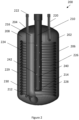
- FIG. 2 shows a cross section of an example heat exchanger accumulator 200 according to an embodiment of the present invention.
- the accumulator heat exchanger 200 comprises an accumulator vessel 202 having an internal volume 208 for accumulation of refrigerant.
- the accumulator vessel 202 of Figure 2 is broadly cylindrical having an axial extent and a radial extent.
- a cap 204 at an axial end of the accumulator vessel provides a slightly domed end to the accumulator vessel 202.
- a first inlet conduit 210 also termed a distributor tube
- a second inlet conduit 220 extend from outside of the accumulator vessel 202 to inside of the accumulator vessel 202. That is, the first and second inlet conduits 210, 220 extend into the internal volume 208 of the accumulator vessel 200.
- a first outlet conduit 212 and a second outlet conduit 222 extend from inside of the accumulator vessel 202 to outside of the accumulator vessel 202. Seals are provided where the first and second inlet conduits 210, 220 and the first and second outlet conduits 212, 222 pass through the cap 204.
- a heat exchange coil 224 is provided within the accumulator vessel 202.
- the heat exchange coil 224 is in the form of a helical coil with a circular cross-section such that it encloses a cylindrical axially extending inner volume 226.
- the second inlet conduit 220 and the second outlet conduit 222 are connected to the heat exchange coil 224 so that the second inlet conduit 220 and the second outlet conduit 222 provide an inlet and outlet flow path for the heat exchange coil 224.
- subcooled refrigerant flows from the second inlet conduit 220, through the heat exchange coil 224, and to the second outlet conduit 222.
- the second inlet conduit 220 introduces subcooled refrigerant to an upper axial end of the heat exchange coil 224. In other examples, the second inlet conduit 220 introduces subcooled refrigerant to a lower axial end of the heat exchange coil 224.
- Liquid refrigerant will pool within the accumulator vessel 202, whereas gaseous refrigerant will flow to the first outlet conduit 212 to be removed from the accumulator vessel 202.
- the first inlet conduit 210 extends from outside of the accumulator vessel 202, through a cap 204 of the accumulator vessel 202 and to an inner axial end 214 of the first inlet conduit 210.
- the axial end 214 of the first inlet conduit is disposed within the inner volume 226 of the heat exchange coil 224.
- refrigerant is therefore delivered to the inner volume 226 of the heat exchange coil 224 by the first inlet conduit 210.
- the first inlet conduit 210 is adapted so that in use refrigerant fluid ejected from the first inlet conduit 210 is directed towards the heat exchange coil 224.
- the heat exchange coil comprises an inner surface 228, which is a radially inner surface.
- the first inlet conduit 210 is disposed within the inner volume 226 of the heat exchange coil 224 such that a circumferentially and axially extending surface 240 of the first inlet conduit faces the radially inner surface 228 of the heat exchange coil.
- refrigerant fluid is directed towards the radially inner surface 228 of the heat exchange coil 224.
- the first inlet conduit 210 comprises outlets within the circumferentially and axially extending surface 240.
- the outlets comprise holes 242 in the circumferentially and axially extending surface 240.
- a plurality of holes 242 are distributed over the circumferentially and axially extending surface 240.
- the heat exchange coil 224 is disposed within the accumulator vessel 202 so as to provide an axially extending outer gap 230 between the inner surface 206 of the accumulator vessel 202 and a radially outer surface 229 of the heat exchange coil 224.
- the outer gap 230 is annular in shape due to the cylindrical form of the accumulator vessel 202 and the heat exchange coil 224.
- gaseous refrigerant within the internal volume 208 of the accumulator vessel 202 will flow from the base of the accumulator vessel, through the annular gap 230 and to an inlet 216 of the first outlet conduit 212.
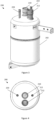
- Figure 3 shows a perspective external view of the accumulator heat exchanger 200.
- the first and second inlet conduits 210, 220 can be seen entering the accumulator vessel 202.
- the first and second outlet conduits 212, 222 can be seen exiting the accumulator vessel 202.
- the first outlet conduit 212 comprises a U turn within the internal volume 208 of the accumulator vessel 202 in order to exit the accumulator vessel 202 at the same axial end as the first inlet conduit 210 enters the accumulator vessel 202.
- Figure 4 shows a plan external view of the accumulator heat exchanger 200.
- the first inlet conduit is shown to be coincident with the central axis of the accumulator vessel 202.
- Figure 5a shows a heat map of a planar slice of the accumulator heat exchanger 100 of Figure 1 , the planar slice comprising the central axes of the accumulator heat exchanger 100.
- the accumulator heat exchanger 100 comprises a first inlet conduit 110 which does not have the capability to direct refrigerant fluid towards the heat exchange coil 124. It can be seen from the temperature data displayed in the heat map that relatively cool refrigerant flows from the outlet 114 of the first inlet conduit 110 towards the base of the internal volume 108 of the accumulator vessel 102.
- the refrigerant flowing from the outlet 114 of the first inlet conduit 110 passes the heat exchange coil 124 without substantial interaction with the coil and without substantial heat transfer between the refrigerant within the internal volume of the accumulator vessel and the refrigerant within the heat exchange coil 124.
- the first outlet conduit 112 is shown in Figure 5a , however the first outlet conduit 212 of the accumulator heat exchanger 200 is offset from the plane illustrated in Figure 5a and so is not shown.
- Figure 5b shows a heat map of a planar slice of an accumulator heat exchanger 200 as described above, the planar slice comprising the central axes of the accumulator heat exchanger 200.
- Refrigerant fluid is introduced into the internal volume 208 of the accumulator vessel 202 via the first inlet conduit (distribution tube) 210.
- the first inlet conduit 210 comprises holes 242 on a circumferentially and axially extending surface 240 which direct the refrigerant fluid towards the heat exchange coil 224. Jets 250 of cold refrigerant can be seen emanating from the holes 242 in the first inlet conduit 210 approaching the heat exchange coil 224.
- the refrigerant entrained in the jets interacts with and is deflected by the heat exchange coil 224.
- the scale used to denote temperature, shown in Figure 5c is the same scale used in both Figure 5a and Figure 5b .
- the temperature is higher in the accumulator vessel 202 shown in Figure 5b compared to the temperature within the accumulator vessel 102 shown in Figure 5a .
- the refrigerant from the first inlet conduit 210 present in the internal volume 208 of the accumulator vessel 202 is at a higher temperature due to more efficient heat exchange with the refrigerant in the heat exchange coil 224.
- Figure 5a shows that, in this example accumulator heat exchanger, the temperature of the refrigerant within the heat exchange coil 124 reduces by around 11 degrees C as it rises from the base of the heat exchange coil 125 to the top of the heat exchange coil 127 within the accumulator heat exchanger 100 shown in Figure 5a .
- Figure 5b shows that, in this particular embodiment, the temperature of the refrigerant within the heat exchange coil 224 reduces by around 15 degrees C as it rises from the base of the heat exchange coil 225 to the top of the heat exchange coil 227.
- the temperature of the refrigerant rising from the base of the heat exchange coil 225 to the top of the heat exchange coil 227 therefore decreases to a greater extent in the accumulator heat exchanger 200 when compared to the accumulator heat exchanger 100.
- refrigerant in the heat exchange coil 224 has been cooled to a greater extent by more efficient heat exchange with the refrigerant from the first inlet conduit 210.
- an improvement of 4 degrees C of cooling has been achieved by the heat exchange coil 224, which is an improvement of about 37% in relation to the 11 degrees C of cooling by the heat exchange coil 125.
- an accumulator heat exchanger comprising a first inlet conduit with a plurality of outlets, each of the plurality of outlets adapted to direct refrigerant fluid towards the heat exchange coil, can result in improvements to the subcooling of refrigerant within the heat exchange coil of around 37% compared to the heat exchanger accumulator 100 of Figure 1 .
- Figure 6 shows a schematic of the first inlet conduit 210.
- the first inlet conduit comprises a circumferentially and axially extending surface 240. Holes 242 are provided in the circumferentially and axially extending surface 240 of the first inlet conduit 210.
- the holes 242 are provided such that there is equal axial distance between those holes that are provided at the same angular rotation around the first inlet conduit 210. In the example shown, the holes 242 are distributed such that there is a 90 degree separation between holes 242 disposed at the same axial height. Four holes are provided at the same axial height. Holes 242a disposed at the same axial height are circumferentially offset by 45 degrees to the holes 242b disposed in an axially adjacent layer. The skilled person will appreciate that the distribution of the holes may be readily altered compared to the example shown in Figure 6 .
- Heat exchange can be increased, for example, by causing the refrigerant within the accumulator vessel to flow along a longer flow path after exiting the first inlet conduit and before entering the first outlet conduit.
- a separator plate may be disposed across the heat exchange coil, e.g. at the top of the coil, e.g.
- Such a separator plate may therefore force refrigerant to flow downwards within the internal volume of the heat exchange coil and then flow upwards in a gap, e.g. gap 230 between the inner surface 206 of the accumulator vessel 202 and a radially outer surface 229 of the heat exchange coil 224 to an inlet 216 of the first outlet conduit 212.
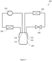
- FIG. 7 shows a schematic of a refrigeration system 300 comprising the accumulator heat exchanger 200 described above.
- the refrigeration system 300 includes a compressor 310, a condenser 320, an expansion valve 330 and an evaporator 340.
- the condenser 320 is connected to the second inlet conduit 220 of the accumulator 200.
- the expansion valve 330 is connected to the second outlet conduit 212 of the accumulator 200.
- Refrigerant flows sequentially from the compressor 310, to the condenser 320, to the heat exchange coil 224 within the accumulator heat exchanger 200, to the expansion valve 330, to the evaporator 340, to the first inlet and first outlet conduits 210, 212 of the accumulator heat exchanger 200 and back to the compressor 310.
- the refrigerant that exits the condenser will be at a relatively high pressure (compared to the refrigerant exiting the evaporator 340) and will be a liquid.
- the condenser 320 causes heat rejection from the refrigerant to the surroundings by cooling the refrigerant to its saturation temperature at which point the gaseous refrigerant condenses to a liquid. The latent heat evolved during the condensation is transferred to the surroundings.
- the condenser 320 may have a sufficient cooling capacity to reduce the temperature of the liquid to below the saturation temperature thereby producing subcooled refrigerant.
- the high pressure within the condenser 320 means that the saturation temperature of the refrigerant is greater than the saturation temperature of the refrigerant in the evaporator 340, which is at a lower pressure.
- the refrigerant temperature of the subcooled liquid refrigerant can hence be greater than the temperature of the gaseous refrigerant supplied by the evaporator 340. Heat is therefore transferred from the subcooled refrigerant in the heat exchange coil 224 to the gaseous refrigerant within the first inlet conduit 210, the accumulator internal volume 208 and the first outlet conduit 212.
- the increased subcooling of the refrigerant exiting the second outlet conduit 222 in turn increases the cooling capacity of the refrigerant such that once it is supplied to the evaporator 340, an increased amount of heat is taken from the surroundings as the liquid evaporates to a gas. As a result, the efficiency of the refrigeration system is increased.
- the refrigeration system 300 and its use is therefore suited to applications such as transport refrigeration where the refrigeration system 300 can be mounted to a vehicle or trailer in operative association with a cargo space within the vehicle or trailer for maintaining a controlled temperature environment within the cargo space.
Landscapes
- Engineering & Computer Science (AREA)
- Physics & Mathematics (AREA)
- Thermal Sciences (AREA)
- Mechanical Engineering (AREA)
- General Engineering & Computer Science (AREA)
- Chemical & Material Sciences (AREA)
- Analytical Chemistry (AREA)
- Power Engineering (AREA)
- Fluid Mechanics (AREA)
- Heat-Exchange Devices With Radiators And Conduit Assemblies (AREA)
Abstract
Description
- The present disclosure relates to an accumulator heat exchanger and a refrigeration system comprising an accumulator heat exchanger. The present disclosure also relates to a method of heat exchange using an accumulator heat exchanger.
- Accumulators are used in refrigeration systems to collect liquid refrigerant and thus prevent liquid refrigerant from passing into the compressor where it can cause damage. Heat exchangers are used in refrigeration systems in order to control the temperature of the refrigerant. It is known to provide accumulator heat exchangers which combine the functions of accumulators and heat exchangers. Accumulator heat exchangers can reduce the temperature of a first refrigerant flow before the refrigerant enters an evaporator in order to increase its cooling capacity, and simultaneously increase the temperature of a second refrigerant flow before the refrigerant enters a compressor in order to promote the formation of gaseous refrigerant from liquid refrigerant. Heat can hence be extracted from the first refrigerant flow to form subcooled refrigerant used within a first portion of the refrigeration system, and that heat can be usefully used for heating the second refrigerant flow to form superheated refrigerant used within a second portion of the refrigeration system.
- It is desirable to increase the heat exchange between the two refrigerant flows in order to further improve cooling capacity of the refrigeration system and the overall efficiency of the refrigeration system.
- It is known to increase the subcooling of the first refrigerant flow using an additional heat exchanger, such as a liquid vapour heat exchanger or a brazed plate heat exchanger, once the refrigerant exits the accumulator and before entering the evaporator. However, integration of the heat exchanger within the refrigeration system can be complicated and the additional component results in a higher cost and the refrigeration system having a larger volume.
- It is therefore also desirable to increase the heat exchange between the two refrigerant flows without increasing the complexity of the refrigeration system and without causing a substantial increase in the space required for the refrigeration system.
- According to a first aspect, there is provided an accumulator heat exchanger for use within a refrigeration system, the accumulator heat exchanger comprising: an accumulator vessel with an internal volume for accumulation of refrigerant fluid; a heat exchange coil disposed within the internal volume of the accumulator vessel wherein the heat exchange coil encloses an axially extending inner volume of the heat exchange coil; a first inlet conduit for introducing refrigerant fluid into the internal volume, the first inlet conduit extending from outside of the accumulator vessel to an inner end of the first inlet conduit within the internal volume of the accumulator vessel, and a first outlet conduit for exhausting superheated gaseous refrigerant from the internal volume, the first outlet conduit extending from within the internal volume of the accumulator vessel to outside of the accumulator vessel; and a second inlet conduit for subcooled refrigerant fluid and a second outlet conduit for subcooled refrigerant fluid, wherein the second inlet conduit and second outlet conduit provide an inlet and outlet flow path for the heat exchange coil; wherein the first inlet conduit comprises a plurality of outlets, each of the plurality of outlets adapted to direct refrigerant fluid towards the heat exchange coil.
- It will be appreciated that refrigerant fluid entering the accumulator vessel via the first inlet conduit may comprise gaseous refrigerant, liquid refrigerant or a mixture of these.
- The accumulator vessel may have an axial extent and a radial extent. The accumulator vessel may be cylindrical, the axial and radial extent of the accumulator vessel following the axial and radial dimensions of the cylinder respectively.
- The heat exchange coil, and the axially extending inner volume defined thereby, may have an axial extent and an extent perpendicular to the axial extent, for example a radial extent. The heat exchange coil and the inner volume defined thereby may therefore comprise an axial direction and a direction perpendicular to the axial direction, for example a radial direction. The axially extending inner volume may be understood as the volume formed at the centre of the coil.
- The inner volume may be understood as having a cross section perpendicular to the axis of the heat exchange coil. The cross section may be uniform over the axial extent of the inner volume, or it may vary over the axial extent. The cross section may be circular, e.g. the heat exchange coil may define an inner volume having a circular cross section. To put it another way, the shape of the area enclosed by the coil at a particular axial position may be circular. In other words, the heat exchange coil may have a circular cross section such that the axially extending inner volume has a circular cross section.
- The inner volume may be cylindrical, e.g. where the cross section is a circular shape and is uniform over the axial extent.
- Other cross-sectional shapes of the inner volume are possible, e.g. the cross section may be oval, square etc. In other words, the heat exchange coil may have an oval cross section such that the axially extending inner volume has an oval cross section. The heat exchange coil may have a square cross section or rectangular cross section such that the axially extending inner volume has a square cross section or rectangular cross section. The inner volume may thereby be a cuboid, e.g. where the cross section is a square/rectangular shape and is uniform over the axial extent.
- The heat exchange coil may be a helical coil. It may be a helical coil with a circular cross section, such that the axially extending inner volume has a circular cross section. Where the cross section is circular and uniform over the axial length then the axially extending inner volume is a cylindrical volume formed at the centre of the coil.
- The heat exchange coil may be a serpentine heat exchange coil.
- The heat exchange coil may comprise an inner surface, i.e. a surface of the coil facing the inner volume of the coil. In other words, the inner surface of the coil comprises the portions of the coil that face inwards, towards the inner volume. This may be a radially inner surface.
- Conversely, the heat exchange coil may be understood as comprising an outer surface, i.e. a surface the coil facing away from the inner volume of the coil. In other words, the outer surface of the coil comprises the portions of the coil that face outwards, towards the outside of the coil. This may be a radially outer surface.
- It will be understood that the inner surface is closer to a central axis of the coil than the outer surface.
- It will be well appreciated that the axially extending inner volume defined by the heat exchange coil is distinct from the internal volume of the pipe forming the coil which comprises the helical refrigerant flow path, i.e. through which the subcooled refrigerant flows.
- The first inlet conduit may extend within the inner volume of the heat exchange coil. The outlets of the first inlet conduit may only be in a portion of the first inlet conduit that extends within the inner volume of the heat exchange coil. The first inlet conduit may be comprised of multiple portions or segments interconnected together.
- The first inlet conduit may be termed a distributor, or it may comprise a portion known as a distributor. The outlets may be in the distributor portion. The distributor portion may be a separate segment connected to another segment of the first inlet conduit or it may be integral therewith.
- The first inlet conduit is adapted to direct gaseous refrigerant towards the heat exchange coil, in other words the first inlet conduit may cause the refrigerant fluid to leave the first inlet conduit in a direction such that the refrigerant fluid approaches the heat exchange coil. The direction of the fluid leaving the first inlet conduit and entering the internal volume of the accumulator vessel may therefore be different to the direction of a refrigerant fluid path which enables gaseous refrigerant to enter the first outlet conduit and then leave the accumulator. The first inlet conduit may be shaped such that that the refrigerant fluid leaving the first inlet conduit approaches the heat exchange coil.
- As discussed above, the heat exchange coil may comprise an inner (e.g. radially inner) surface. Each outlet may be adapted to direct refrigerant fluid towards the inner (e.g. radially inner) surface of the heat exchange coil.
- The first inlet conduit may comprise a portion that extends into the axially extending inner volume enclosed by the heat exchange coil. The heat exchange coil may then comprise an inner surface (e.g. as discussed above) that faces the first inlet conduit. The first inlet conduit may be adapted to provide a component to the direction of the flow of the refrigerant fluid leaving the first inlet conduit which is in a direction perpendicular to the axial extent of the heat exchange coil. The refrigerant fluid may therefore be directed towards the inner surface of the heat exchange coil. Optionally, the first inlet conduit may be adapted to cause the refrigerant fluid leaving the first inlet conduit to flow in a direction substantially perpendicular to the axial extent of the heat exchange coil. Optionally, the first inlet conduit may be adapted to cause the refrigerant fluid leaving the first inlet conduit to flow in a direction substantially perpendicular to a length or axial extent of the first inlet conduit.
- The outlets, or openings, allow the refrigerant to exit the first inlet conduit. The refrigerant fluid is thereby influenced by the shape and/or positioning of the outlets, and it is this influence that causes the refrigerant to flow towards the heat exchange coil. The outlets may be provided via an appendage or additional component added to the first inlet conduit which affects the direction of the refrigerant fluid in order to provide that the refrigerant fluid leaving the first inlet conduit approaches the heat exchange coil. For example, the appendage may comprise spouts or piping.
- The plurality of outlets may comprise between 2 and 100 outlets, or may comprise between 4 and 60 outlets, or may comprise between 8 and 40 outlets, or may comprise between 16 and 32 outlets.
- The first inlet conduit may be substantially cylindrical or comprise a substantially cylindrical portion. The first inlet conduit may be tubular, for example it may comprise a tube. The first inlet conduit may be termed a distributor tube.
- The closer the refrigerant fluid within the internal volume of the accumulator vessel gets to the heat exchange coil, the greater the heat exchange rate between the refrigerant fluid within the internal volume of the accumulator vessel and the subcooled refrigerant in the heat exchange coil.
- Similarly, the greater the mixing of the refrigerant within the internal volume of the accumulator vessel, the greater the heat exchange between the refrigerant fluid within the internal volume of the accumulator vessel and the subcooled refrigerant in the heat exchange coil. Thus, by causing the refrigerant leaving the first inlet conduit to flow in a direction other than the route to the first outlet conduit, and by causing the refrigerant to impact on the heat exchange coil, greater turbulence is created within the accumulator vessel and so greater mixing of the refrigerant within the internal volume of the accumulator vessel will occur. A larger volume of refrigerant will then flow close to the heat exchange coil so that greater heat exchange occurs.
- An inlet of the first outlet conduit may be located within the accumulator vessel such that refrigerant leaving the first inlet conduit is not directed towards the inlet of the first outlet conduit. Thus, the inlet of the first outlet conduit may be misaligned vertically or horizontally or both from the position at which the refrigerant leaves the first inlet conduit. By locating the inlet of the first outlet conduit away from the first inlet conduit such that there is no direct path for refrigerant to flow between the two without impacting on a surface of the heat exchange coil, a surface of the accumulator vessel, or being forced along a path with changes in direction, direct sucking of the refrigerant out of the accumulator vessel before significant heat exchange can occur is avoided.
- Greater turbulence where the refrigerant fluid meets the heat exchange coil will also reduce the boundary layer in the fluid flowing past the heat exchange coil. This also acts to increase heat transfer between the refrigerant in the internal volume of the accumulator vessel and the heat exchange coil.
- Thus, by directing the refrigerant fluid leaving the first inlet conduit towards the heat exchange coil from multiple outlets, heat exchange is significantly increased, e.g. the heat exchange coefficient is increased. The temperature of the superheated refrigerant within the internal volume of the accumulator vessel can be increased by a greater amount. The temperature of the subcooled refrigerant within the heat exchange coil can be reduced by a greater amount (i.e. subcooling is increased). The efficiency of the accumulator heat exchanger can thus be increased. As a result, the cooling capacity of the accumulator heat exchanger can be increased compared to the prior art. Advantageously, the increased cooling capacity of the accumulator heat exchanger is increased without increasing the dimensions of the accumulator exchanger, and without substantially increasing the complexity of the system. The integrated accumulator heat exchanger provided according to the present disclosure is less expensive than providing an accumulator and separate heat exchanger, and is less complex and more efficient to integrate into a refrigeration system than an accumulator and separate heat exchanger.
- Optionally, the first inlet conduit may be adapted to cause the refrigerant fluid to leave the first inlet conduit at a higher velocity than the velocity at which the refrigerant fluid entered the first inlet conduit. The increased velocity will assist in the refrigerant fluid approaching the heat exchange coil and the mixing of and turbulence within the refrigerant within the internal volume of the accumulator vessel. Thus, heat exchange between the refrigerant in the internal volume of the accumulator vessel and the refrigerant within the heat exchange coil will be increased.
- The first inlet conduit may extend axially within the inner volume of the heat exchange coil. The first inlet conduit may be closed at its inner end, this may be an inner axial end. By being closed at its inner end, the refrigerant fluid is forced to exit through the outlets in the first inlet conduit. This creates a high velocity jet towards the heat exchange coil.
- The first inlet conduit may comprise a circumferentially and axially extending surface. The plurality of outlets may be provided in the circumferentially and axially extending surface. The outlets may comprise holes provided in the circumferentially and axially extending surface.
- The first inlet conduit may extend parallel to the axial direction of the axially extending inner volume of the heat exchange coil, or may extend in a direction having a component parallel to the axial direction of the axially extending inner volume of the heat exchange coil. A central axis of the first inlet conduit may be coincident with a central axis of the inner volume of the heat exchange coil, or it may be offset therefrom.
- Similarly to the first inlet conduit, the first outlet conduit may comprise a circumferentially and axially extending surface. The first outlet conduit may comprise a substantially cylindrical portion. Similarly to the first inlet conduit, the first outlet conduit may also extend axially within the inner volume of the heat exchange coil. The first inlet and first outlet conduits may extend at least partly parallel to each other within the inner volume of the heat exchange coil.
- The first inlet conduit may be closed at its inner axial end so that refrigerant is prevented from leaving the first inlet conduit in an axial direction relative to the heat exchange coil. The inner axial end may be the final portion of the first inlet conduit, the final portion being at the greatest distance tracked by the flow of the refrigerant within the inlet conduit from the portion of the first inlet conduit where the refrigerant first enters the accumulator vessel. The inner axial end of the inlet conduit may be closed via a radially and circumferentially extending surface, or the inner axial end may be shaped in any other way such that there is no opening that would allow refrigerant to leave the first inlet conduit in a direction parallel to the axial direction of the inner volume of the heat exchange coil.
- The plurality of outlets may be provided in the form of a plurality of holes where there is material missing from the axially and circumferentially extending surface of the first inlet conduit. The holes may be of any shape, for example they may be circular, square, hexagonal or any other shape. The holes may be the same shape, or the holes may be of differing shapes.
- At least some of the holes may be circumferentially distributed around the circumferentially and axially extending surface of the first inlet conduit.
- The position of the plurality of holes may be distributed around the circumferentially and axially extending surface of the first inlet conduit so that refrigerant is directed towards the heat exchange coil at multiple angular positions.
- The plurality of holes may be equally spaced around the circumference of the circumferentially and axially extending surface of the inlet conduit so that the angular distance between each hole is consistent. For example, in the case where there are four holes the holes may be separated by an angular rotation of 90 degrees, and for the case where there are 5 holes the holes may be separated by an angular rotation of 72 degrees.
- At least some of the holes may be axially distributed along the circumferentially and axially extending surface of the first inlet conduit.
- The position of the plurality of holes may be distributed over the circumferentially and axially extending surface of the first inlet conduit so that refrigerant is directed towards the heat exchange coil at multiple axial heights.
- The plurality of holes may be equally spaced along the axial length of the circumferentially and axially extending surface of the inlet conduit so that the axial distance between each is hole is consistent.
- Typically, a plurality of holes may be distributed both circumferentially around and axially along the circumferentially and axially extending surface of the inlet conduit. This maximises the distribution of refrigerant over the heat exchange coil and thus maximises heat exchange.
- Where there is both a plurality of holes circumferentially distributed around the circumferentially and axially extending surface of the inlet conduit and a plurality of holes axially distributed along the inlet conduit, the circumferential/angular separation between each hole may be consistent within a set of those plurality of holes. For example, there may be four holes at a single axial height and they may each be separated by 90 degrees around the circumference of the first inlet pipe, there may be a further four holes at a separate height and each of these four holes may be separated by 90 degrees around the circumference of the first inlet conduit. There may be an equal axial distance between holes provided at the same angular position. In some examples there may be a set of holes which are spaced at equal angular separations around the circumference of the first inlet pipe, but some or all of the holes may be axially offset from the other holes within that set.
- The holes may have a diameter in the range of 1 to 10 mm, optionally the holes have a diameter in the range of 2 to 8 mm, optionally the holes have a diameter of 5 mm. The holes may have differing diameters, e.g. some may have a diameter in one of these ranges, and others may have a diameter in other(s) of the ranges.
- The holes may be sized in order to control the velocity of the refrigerant fluid leaving the first inlet conduit. The holes may be small in order to increase the velocity of the refrigerant fluid. However, the holes must not be so small that functioning of the accumulator heat exchanger is impaired by the pressure required for refrigerant to flow through the holes of the first inlet pipe being too great. In the case in which there is more than one hole, the holes may be of equal size, or the holes may be of differing size. The holes may be circular and their diameter may be in the range of 1 to 10 mm, optionally the one or more holes have a diameter in the range of 2 to 8 mm, optionally the one or more holes have a diameter of 5 mm. Similarly, the holes may be square and their width may be in the range of 1 to 10 mm, in the range of 2 to 8 mm, or may be 5 mm. The holes may be any other shape and their principal or longest length may be in the range of 1 to 10 mm, in the range of 2 to 8 mm, or may be 5 mm.
- One or more of the plurality of outlets in the first inlet conduit may comprise a nozzle. In other words a nozzle may be provided at one or more of the outlets in the first inlet conduit.
- A nozzle may be provided at each of the outlets in the first inlet conduit. In examples where the outlets are holes, a nozzle may be provided at one or more or each of the holes within the circumferentially and axially extending surface of the first inlet conduit.
- The nozzle(s) may be an additional component or additional material positioned at the outlets in order to act as a spout for controlling a jet of refrigerant fluid exiting the first inlet conduit through the outlet. The nozzle(s) may therefore be capable of determining or controlling the direction and/or the velocity of the jet.
- The heat exchange coil may for example be a circular helical coil. The heat exchange coil may comprise a pitch. The pitch of the heat exchange coil may be constant or may vary along the axial length of the coil. The pitch may be such that either: i) adjacent windings are not in contact, ii) adjacent windings are in contact, or iii) the pitch varies along the length of the heat exchange coil such that a first portion of adjacent windings are in contact and a second portion of adjacent windings are not in contact.
- The pitch of the heat exchange coil may be such that adjacent windings are not in contact. Adjacent windings of the heat exchange coil may not be in contact with another but may be in close proximity in order to provide a small flow path for refrigerant to pass between the windings. Gaps between adjacent windings may be sized so that significant turbulence is induced within the refrigerant as it passes therethrough.
- Where there is no contact, or only a small space, between adjacent windings, turbulence will be induced within the refrigerant as it flows past the windings and through the axially and circumferentially extending surface of the coil. This increased turbulence will increase the heat exchange between the refrigerant and the heat exchange coil. Furthermore, by allowing flow between windings, the flow will contact a greater heat exchange surface of the coil thus increasing heat exchange.
- The pitch of the heat exchange coil may be such that adjacent windings are in contact. Adjacent windings of the heat exchange coil may be in contact with one another so that there is no flow path available for refrigerant to pass between the windings.
- Where there is contact between adjacent windings of the heat exchange coil, there is no route for any meaningful flow of refrigerant within the accumulator vessel to pass through the axially and circumferentially extending surface of the coil. Therefore, by providing the coil with regions of contact between adjacent windings, when in use the volume of refrigerant passing from within the inner volume of the coil to outside of the inner volume of the heat exchange coil by passing through the an axially extending surface of the helical coil is reduced. In some embodiments, adjacent windings are in sufficient, sustained contact such that there is no route for refrigerant to pass from within the inner volume of the coil to outside of the inner volume of the heat exchange coil without first exiting the inner volume of the heat exchange coil at an axial end of the coil. In some implementations the adjacent windings are sealed together in order to fully prevent flow between adjacent windings.
- The pitch of the heat exchange coil may vary along the length of the heat exchange coil such that a first portion of adjacent windings are in contact and a second portion of adjacent windings are not in contact. The extent of contact between adjacent windings of the heat exchange coil may vary along the length of the heat exchange coil. The first portion of adjacent windings may comprise a plurality of sections of windings of the heat exchange coil separated by a plurality of sections of windings of the heat exchange coil which form the second portion of adjacent windings.
- The first inlet conduit may be coincident with a longitudinal axis of the heat exchange coil.
- Thus, the first inlet conduit may extend through the inner volume of the heat exchange coil along the centre line of the heat exchange coil. Where the heat exchange coil is positioned centrally within the accumulator vessel, i.e. the longitudinal axis of the heat exchange coil is aligned with a central axis of the accumulator vessel, the first inlet conduit may therefore also extend along the central axis of the accumulator vessel.
- According to a second aspect, a refrigeration system is provided. The refrigeration system comprises the accumulator heat exchanger according to the first aspect and optionally including any other features as described above, a compressor, an evaporator, an expansion valve, and a condenser, wherein the first inlet conduit and the first outlet conduit are positioned between the evaporator and the compressor such that a first refrigerant flow path extends sequentially from the evaporator to the first inlet conduit, to the first outlet conduit and to the compressor, and the second inlet conduit and second outlet conduit are positioned between the condenser and the expansion valve such that a second refrigerant flow path extends sequentially from the condenser to the second inlet conduit, to the second outlet conduit and to the expansion valve.
- In some embodiments, the first refrigerant flow path may extend directly from the evaporator to the first inlet conduit and/or directly from the first outlet conduit to the compressor, that is, without passing through another component in between, besides the connecting refrigerant lines or pipes. In other embodiments, the first refrigerant flow path may extend through additional components in between the evaporator and the first inlet conduit, and/or additional components between the first outlet conduit and the compressor, but will maintain the sequence recited above with respect to the evaporator, first inlet conduit, first outlet conduit and compressor.
- In some embodiments, the second refrigerant flow path may extend directly from the condenser to the second inlet conduit and/or directly from the second outlet conduit to the expansion valve, that is, without passing through another component in between, besides the connecting refrigerant lines or pipes. In other embodiments, the second refrigerant flow path may extend through additional components in between the condenser and the second inlet conduit, and/or additional components between the second outlet conduit and the expansion valve, but will maintain the sequence recited above with respect to the condenser, second inlet conduit, second outlet conduit and expansion valve.
- The first inlet conduit may be directly connected to the evaporator.
- A flow path is therefore provided between the evaporator and the first inlet conduit, and besides the connecting refrigerant lines or pipes, this flow path does not extend through any additional component in between the evaporator and first inlet conduit.
- The first outlet conduit may be directly connected to the compressor.
- A flow path is therefore provided between the first outlet conduit and the compressor, and besides the connecting refrigerant lines or pipes, this flow path does not extend through any additional component in between the first outlet conduit and the compressor.
- The refrigeration system may be suitable for use in a transportation application. For example, the refrigeration system may be suitable for use in a refrigerated vehicle and/or trailer. Such refrigerated vehicles and trailers are commonly used to transport perishable goods in a cold chain distribution system. The refrigeration system may be mounted to the vehicle or to the trailer in operative association with a cargo space within the vehicle or trailer for maintaining a controlled temperature environment within the cargo space.
- The refrigeration system may be suitable for use in HVAC systems or air conditioning systems which can be installed in buildings, vehicles, or the like.
- The refrigeration system may comprise a plurality of evaporators.
- The first inlet conduit may receive refrigerant fluid from each of the plurality of evaporators. The temperature of the refrigerant fluid received from each of the evaporators may differ. In other words, the refrigeration system may be a multi-temperature system.
- The plurality of evaporators may be provided within the refrigeration system connected in parallel.
- The accumulator heat exchanger according to the first aspect and optionally including any other features as described above provides particular advantages in refrigeration systems comprising multiple evaporators. Due to the improved heat exchange with the described accumulator heat exchanger, the single accumulator heat exchanger can be used rather than providing a separate external heat exchanger per evaporator. This is less expensive that utilising a separate external heat exchanger for each evaporator. Moreover, due to a decrease in the number of components, and a decrease in the number of joints required within the refrigerant flow path, there is a reduced leakage of refrigerant.
- According to another aspect, there is provided a method of heat exchange using an accumulator heat exchanger according to the first aspect and optionally including any other features as described above. The method comprises: supplying refrigerant fluid into the first inlet conduit; and distributing refrigerant fluid towards the heat exchange coil through the plurality of outlets.
- The first inlet conduit thereby introduces refrigerant fluid into the internal volume of the accumulator vessel. The second inlet conduit introduces subcooled refrigerant into the heat exchange coil within the accumulator vessel.
- A mixture of gaseous refrigerant and liquid refrigerant may enter the accumulator vessel through the first inlet conduit. Liquid refrigerant may accumulate in a pool within the accumulator vessel and may be periodically vaporized from the accumulator vessel. Gaseous refrigerant may accumulate throughout the vessel, and may generally flow from the first inlet conduit to the inlet of the first outlet conduit.
- The refrigerant will exit the first inlet conduit and be directed towards the heat exchange coil. Distributing refrigerant fluid towards the heat exchange coil through the plurality of outlets may comprise providing refrigerant fluid through a plurality of holes within a circumferentially and axially extending surface of the first inlet conduit.
- The gaseous refrigerant will become superheated gaseous refrigerant as it travels through the accumulator vessel due to heat exchange with subcooled refrigerant in the heat exchange coil. Superheated refrigerant is at a temperature greater than the dew vapor point of the refrigerant. Subcooled refrigerant is at a temperature lower than the bubble (liquid) point of the refrigerant.
- The gaseous refrigerant within the first inlet conduit, the accumulator vessel and the first outlet conduit is at a lower pressure than the refrigerant within the second inlet conduit, heat exchange coil and the second outlet conduit. As a result, the dew vapour point of the refrigerant within the first inlet conduit, the accumulator vessel and the first outlet conduit will be lower than that of the refrigerant within the second inlet conduit, heat exchange coil and the second outlet conduit.
Consequently, the gaseous refrigerant can be at a lower temperature than the subcooled liquid refrigerant. Heat exchange therefore takes place via heat transfer from the subcooled liquid refrigerant within the heat exchange coil to the refrigerant fluid within the internal volume of the accumulator vessel. The accumulator heat exchanger therefore acts to further cool the subcooled refrigerant and to further heat the refrigerant fluid within the internal volume of the accumulator vessel to form a superheated gaseous refrigerant. As a result, evaporation of the refrigerant fluid supplied via the first inlet conduit is promoted and the volume of liquid refrigerant accumulation in the accumulator is reduced. The subcooled refrigerant leaving the accumulator heat exchanger also has a greater cooling capacity as a result of its decreased temperature. - The accumulator heat exchanger in this method of heat exchange may be part of a refrigeration system, wherein the refrigeration system comprises; a compressor, an evaporator, an expansion valve, and a condenser, and the method of heat exchange comprises; supplying refrigerant from the evaporator to the first inlet conduit, supplying superheated gaseous refrigerant from the first outlet conduit to the compressor, supplying subcooled liquid refrigerant from the condenser to the second inlet conduit, and supplying subcooled liquid refrigerant from the second outlet conduit to the expansion valve.
- In some embodiments, the refrigerant fluid may be supplied directly from the evaporator to the first inlet conduit and/or the superheated gaseous refrigerant may be supplied directly from the first outlet conduit to the compressor, that is, without passing through another component in between. In other embodiments, the refrigerant may flow through additional components in between the evaporator and the first inlet conduit, and/or additional components between the first outlet conduit and the compressor, but will maintain the sequence recited above with respect to the evaporator, first inlet conduit, first outlet conduit and compressor.
- In some embodiments, subcooled refrigerant may be supplied directly from the condenser to the second inlet conduit and/or may be supplied directly from the second outlet conduit to the expansion valve, that is, without passing through another component in between. In other embodiments, subcooled refrigerant may flow through additional components in between the condenser and the second inlet conduit, and/or additional components between the second outlet conduit and the expansion valve, but will maintain the sequence recited above with respect to the condenser, second inlet conduit, second outlet conduit and expansion valve.
- Refrigerant fluid may be supplied to the first inlet conduit directly from the evaporator. Refrigerant fluid is thereby supplied to the accumulator vessel from the evaporator without the gaseous refrigerant entering an additional component between the evaporator and the first inlet conduit. A combination of gaseous refrigerant and liquid refrigerant may be provided to the accumulator vessel from the evaporator through the first inlet conduit.
- Superheated gaseous refrigerant may be supplied directly from the first outlet conduit to the compressor. Superheated gaseous refrigerant is therefore provided to the compressor from the accumulator vessel without passing through an additional component of the refrigeration system between the first outlet conduit and the compressor. Any liquid refrigerant introduced into the accumulator vessel will pool within the vessel and will not flow through the first outlet conduit to the compressor.
- Certain embodiments of the invention will now be described by way of example only and with reference to the accompanying drawings in which:
-
Figure 1 shows a perspective view of a cross section of an accumulator heat exchanger; -
Figure 2 shows a perspective view of a cross section of an accumulator heat exchanger according to an embodiment of the present invention; -
Figure 3 shows a perspective external view of the accumulator heat exchanger ofFigure 2 ; -
Figure 4 shows a plan view of the accumulator heat exchanger ofFigure 2 ; -
Figure 5a shows a heat map of a planar slice of the accumulator heat exchanger ofFigure 1 ; -
Figure 5b shows a heat map of a planar slice of the accumulator heat exchanger ofFigure 2 ; -
Figure 5c shows the scale used inFigures 5a and 5b to represent the temperature of the accumulator heat exchangers; -
Figure 6 shows a perspective view of a first inlet conduit provided within the accumulator heat exchanger ofFigure 2 ; and -
Figure 7 shows a schematic view of a refrigeration system including the accumulator heat exchanger ofFigure 2 . - As seen in
Figure 1 , anaccumulator heat exchanger 100 comprises anaccumulator vessel 102 having aninternal volume 108 for accumulation of refrigerant. Theaccumulator vessel 102 ofFigure 1 is broadly cylindrical having an axial extent and a radial extent. Acap 104 at an axial end of the accumulator vessel provides a slightly domed end to theaccumulator vessel 102. Afirst inlet conduit 110 and asecond inlet conduit 111 extend from outside of theaccumulator vessel 102 to inside of theaccumulator vessel 102. That is, thefirst inlet conduit 110 and thesecond inlet conduit 111 extend into theinternal volume 108 of theaccumulator vessel 100. Afirst outlet conduit 112 and asecond outlet conduit 113 extend from inside of theaccumulator vessel 102 to outside of theaccumulator vessel 102. - As seen in
Figure 1 , aheat exchange coil 124 is provided within theaccumulator vessel 102. Theheat exchange coil 124 is in the form of a helical coil with a circular cross-section such that it encloses a cylindrical axially extendinginner volume 126. - The
second inlet conduit 111 and thesecond outlet conduit 113 are connected to theheat exchange coil 124 so that thesecond inlet conduit 111 and thesecond outlet conduit 113 provide an inlet and outlet flow path for theheat exchange coil 124. In use, subcooled refrigerant flows from thesecond inlet conduit 111, through theheat exchange coil 124, and to thesecond outlet conduit 113. In the example shown, thesecond inlet conduit 111 introduces subcooled refrigerant to an upper axial end of theheat exchange coil 124. In other examples, thesecond inlet conduit 111 introduces subcooled refrigerant to a lower axial end of theheat exchange coil 124. - In use, refrigerant is delivered to the
internal volume 108 of theaccumulator vessel 102 by thefirst inlet conduit 110. Liquid refrigerant will pool within theaccumulator vessel 102, whereas gaseous refrigerant will flow to thefirst outlet conduit 112 to be removed from theaccumulator vessel 102. - In this system, gaseous refrigerant exits the
first inlet conduit 110 via an opening at theaxial end 114 of thefirst inlet conduit 110 and will thus flow down towards the base of theaccumulator vessel 102. -
Figure 2 shows a cross section of an exampleheat exchanger accumulator 200 according to an embodiment of the present invention. Theaccumulator heat exchanger 200 comprises anaccumulator vessel 202 having aninternal volume 208 for accumulation of refrigerant. Theaccumulator vessel 202 ofFigure 2 is broadly cylindrical having an axial extent and a radial extent. Acap 204 at an axial end of the accumulator vessel provides a slightly domed end to theaccumulator vessel 202. A first inlet conduit 210 (also termed a distributor tube) and asecond inlet conduit 220 extend from outside of theaccumulator vessel 202 to inside of theaccumulator vessel 202. That is, the first andsecond inlet conduits internal volume 208 of theaccumulator vessel 200. Afirst outlet conduit 212 and asecond outlet conduit 222 extend from inside of theaccumulator vessel 202 to outside of theaccumulator vessel 202. Seals are provided where the first andsecond inlet conduits second outlet conduits cap 204. - As seen in
Figure 2 , aheat exchange coil 224 is provided within theaccumulator vessel 202. Theheat exchange coil 224 is in the form of a helical coil with a circular cross-section such that it encloses a cylindrical axially extendinginner volume 226. Thesecond inlet conduit 220 and thesecond outlet conduit 222 are connected to theheat exchange coil 224 so that thesecond inlet conduit 220 and thesecond outlet conduit 222 provide an inlet and outlet flow path for theheat exchange coil 224. In use, subcooled refrigerant flows from thesecond inlet conduit 220, through theheat exchange coil 224, and to thesecond outlet conduit 222. In the example shown, thesecond inlet conduit 220 introduces subcooled refrigerant to an upper axial end of theheat exchange coil 224. In other examples, thesecond inlet conduit 220 introduces subcooled refrigerant to a lower axial end of theheat exchange coil 224. - Liquid refrigerant will pool within the
accumulator vessel 202, whereas gaseous refrigerant will flow to thefirst outlet conduit 212 to be removed from theaccumulator vessel 202. - The
first inlet conduit 210 extends from outside of theaccumulator vessel 202, through acap 204 of theaccumulator vessel 202 and to an inneraxial end 214 of thefirst inlet conduit 210. Theaxial end 214 of the first inlet conduit is disposed within theinner volume 226 of theheat exchange coil 224. In use, refrigerant is therefore delivered to theinner volume 226 of theheat exchange coil 224 by thefirst inlet conduit 210. Thefirst inlet conduit 210 is adapted so that in use refrigerant fluid ejected from thefirst inlet conduit 210 is directed towards theheat exchange coil 224. - The heat exchange coil comprises an
inner surface 228, which is a radially inner surface. Thefirst inlet conduit 210 is disposed within theinner volume 226 of theheat exchange coil 224 such that a circumferentially and axially extendingsurface 240 of the first inlet conduit faces the radiallyinner surface 228 of the heat exchange coil. In use, refrigerant fluid is directed towards the radiallyinner surface 228 of theheat exchange coil 224. - The
first inlet conduit 210 comprises outlets within the circumferentially and axially extendingsurface 240. The outlets compriseholes 242 in the circumferentially and axially extendingsurface 240. A plurality ofholes 242 are distributed over the circumferentially and axially extendingsurface 240. - The
heat exchange coil 224 is disposed within theaccumulator vessel 202 so as to provide an axially extendingouter gap 230 between theinner surface 206 of theaccumulator vessel 202 and a radiallyouter surface 229 of theheat exchange coil 224. Theouter gap 230 is annular in shape due to the cylindrical form of theaccumulator vessel 202 and theheat exchange coil 224. - In use, gaseous refrigerant within the
internal volume 208 of theaccumulator vessel 202 will flow from the base of the accumulator vessel, through theannular gap 230 and to aninlet 216 of thefirst outlet conduit 212. -
Figure 3 shows a perspective external view of theaccumulator heat exchanger 200. The first andsecond inlet conduits accumulator vessel 202. The first andsecond outlet conduits accumulator vessel 202. It will be appreciated that thefirst outlet conduit 212 comprises a U turn within theinternal volume 208 of theaccumulator vessel 202 in order to exit theaccumulator vessel 202 at the same axial end as thefirst inlet conduit 210 enters theaccumulator vessel 202. -
Figure 4 shows a plan external view of theaccumulator heat exchanger 200. The first inlet conduit is shown to be coincident with the central axis of theaccumulator vessel 202. -
Figure 5a shows a heat map of a planar slice of theaccumulator heat exchanger 100 ofFigure 1 , the planar slice comprising the central axes of theaccumulator heat exchanger 100. Theaccumulator heat exchanger 100 comprises afirst inlet conduit 110 which does not have the capability to direct refrigerant fluid towards theheat exchange coil 124. It can be seen from the temperature data displayed in the heat map that relatively cool refrigerant flows from theoutlet 114 of thefirst inlet conduit 110 towards the base of theinternal volume 108 of theaccumulator vessel 102. As can be seen within box A ofFigure 5a , the refrigerant flowing from theoutlet 114 of thefirst inlet conduit 110 passes theheat exchange coil 124 without substantial interaction with the coil and without substantial heat transfer between the refrigerant within the internal volume of the accumulator vessel and the refrigerant within theheat exchange coil 124. Thefirst outlet conduit 112 is shown inFigure 5a , however thefirst outlet conduit 212 of theaccumulator heat exchanger 200 is offset from the plane illustrated inFigure 5a and so is not shown. -
Figure 5b shows a heat map of a planar slice of anaccumulator heat exchanger 200 as described above, the planar slice comprising the central axes of theaccumulator heat exchanger 200. Refrigerant fluid is introduced into theinternal volume 208 of theaccumulator vessel 202 via the first inlet conduit (distribution tube) 210. Thefirst inlet conduit 210 comprisesholes 242 on a circumferentially and axially extendingsurface 240 which direct the refrigerant fluid towards theheat exchange coil 224.Jets 250 of cold refrigerant can be seen emanating from theholes 242 in thefirst inlet conduit 210 approaching theheat exchange coil 224. As can be seen in box B, the refrigerant entrained in the jets interacts with and is deflected by theheat exchange coil 224. - The scale used to denote temperature, shown in
Figure 5c , is the same scale used in bothFigure 5a and Figure 5b . When comparing the temperature of the refrigerant within theinternal volume accumulator vessels heat exchange coil accumulator vessel 202 shown inFigure 5b compared to the temperature within theaccumulator vessel 102 shown inFigure 5a . In other words, the refrigerant from thefirst inlet conduit 210 present in theinternal volume 208 of theaccumulator vessel 202 is at a higher temperature due to more efficient heat exchange with the refrigerant in theheat exchange coil 224. -
Figure 5a shows that, in this example accumulator heat exchanger, the temperature of the refrigerant within theheat exchange coil 124 reduces by around 11 degrees C as it rises from the base of theheat exchange coil 125 to the top of theheat exchange coil 127 within theaccumulator heat exchanger 100 shown inFigure 5a . -
Figure 5b shows that, in this particular embodiment, the temperature of the refrigerant within theheat exchange coil 224 reduces by around 15 degrees C as it rises from the base of theheat exchange coil 225 to the top of theheat exchange coil 227. The temperature of the refrigerant rising from the base of theheat exchange coil 225 to the top of theheat exchange coil 227 therefore decreases to a greater extent in theaccumulator heat exchanger 200 when compared to theaccumulator heat exchanger 100. In other words, refrigerant in theheat exchange coil 224 has been cooled to a greater extent by more efficient heat exchange with the refrigerant from thefirst inlet conduit 210. In this example, an improvement of 4 degrees C of cooling has been achieved by theheat exchange coil 224, which is an improvement of about 37% in relation to the 11 degrees C of cooling by theheat exchange coil 125. - In general, use of an accumulator heat exchanger comprising a first inlet conduit with a plurality of outlets, each of the plurality of outlets adapted to direct refrigerant fluid towards the heat exchange coil, can result in improvements to the subcooling of refrigerant within the heat exchange coil of around 37% compared to the
heat exchanger accumulator 100 ofFigure 1 . -
Figure 6 shows a schematic of thefirst inlet conduit 210. The first inlet conduit comprises a circumferentially and axially extendingsurface 240.Holes 242 are provided in the circumferentially and axially extendingsurface 240 of thefirst inlet conduit 210. - In the example shown, the
holes 242 are provided such that there is equal axial distance between those holes that are provided at the same angular rotation around thefirst inlet conduit 210. In the example shown, theholes 242 are distributed such that there is a 90 degree separation betweenholes 242 disposed at the same axial height. Four holes are provided at the same axial height.Holes 242a disposed at the same axial height are circumferentially offset by 45 degrees to theholes 242b disposed in an axially adjacent layer. The skilled person will appreciate that the distribution of the holes may be readily altered compared to the example shown inFigure 6 . - Additional parts may be added within the accumulator vessel to enhance the heat exchange between the refrigerant in the accumulator vessel and the refrigerant in the heat exchange coil. Heat exchange can be increased, for example, by causing the refrigerant within the accumulator vessel to flow along a longer flow path after exiting the first inlet conduit and before entering the first outlet conduit. For example, a separator plate may be disposed across the heat exchange coil, e.g. at the top of the coil, e.g. outside of the inner volume of the heat exchange coil and in contact with a top axial end of the heat exchange coil, such that the outlets of the first inlet conduit are disposed on a first side of the separator plate and the inlet of the first outlet conduit is disposed on a second side of the separator plate opposite the first side. Such a separator plate may therefore force refrigerant to flow downwards within the internal volume of the heat exchange coil and then flow upwards in a gap,
e.g. gap 230 between theinner surface 206 of theaccumulator vessel 202 and a radiallyouter surface 229 of theheat exchange coil 224 to aninlet 216 of thefirst outlet conduit 212. -
Figure 7 shows a schematic of arefrigeration system 300 comprising theaccumulator heat exchanger 200 described above. Therefrigeration system 300 includes acompressor 310, acondenser 320, anexpansion valve 330 and anevaporator 340. Thecondenser 320 is connected to thesecond inlet conduit 220 of theaccumulator 200. Theexpansion valve 330 is connected to thesecond outlet conduit 212 of theaccumulator 200. - Refrigerant flows sequentially from the
compressor 310, to thecondenser 320, to theheat exchange coil 224 within theaccumulator heat exchanger 200, to theexpansion valve 330, to theevaporator 340, to the first inlet andfirst outlet conduits accumulator heat exchanger 200 and back to thecompressor 310. - The refrigerant that exits the condenser will be at a relatively high pressure (compared to the refrigerant exiting the evaporator 340) and will be a liquid. The
condenser 320 causes heat rejection from the refrigerant to the surroundings by cooling the refrigerant to its saturation temperature at which point the gaseous refrigerant condenses to a liquid. The latent heat evolved during the condensation is transferred to the surroundings. Thecondenser 320 may have a sufficient cooling capacity to reduce the temperature of the liquid to below the saturation temperature thereby producing subcooled refrigerant. The high pressure within thecondenser 320 means that the saturation temperature of the refrigerant is greater than the saturation temperature of the refrigerant in theevaporator 340, which is at a lower pressure. The refrigerant temperature of the subcooled liquid refrigerant can hence be greater than the temperature of the gaseous refrigerant supplied by theevaporator 340. Heat is therefore transferred from the subcooled refrigerant in theheat exchange coil 224 to the gaseous refrigerant within thefirst inlet conduit 210, the accumulatorinternal volume 208 and thefirst outlet conduit 212. - The increased subcooling of the refrigerant exiting the
second outlet conduit 222 in turn increases the cooling capacity of the refrigerant such that once it is supplied to theevaporator 340, an increased amount of heat is taken from the surroundings as the liquid evaporates to a gas. As a result, the efficiency of the refrigeration system is increased. - Increasing the heat of the refrigerant supplied to the
accumulator vessel 202 via thefirst inlet conduit 210 will reduce the proportion of that refrigerant in the liquid phase within theaccumulator vessel 202. As a result, less liquid refrigerant accumulates in the accumulator and a greater amount of gaseous refrigerant is available to continue through the refrigeration system. - Use of the
accumulator heat exchanger 200 described above within thisrefrigeration system 300 allows for these benefits to be achieved whilst avoiding increasing the complexity of therefrigeration system 300 and without increasing the space required for therefrigeration system 300. Therefrigeration system 300 and its use is therefore suited to applications such as transport refrigeration where therefrigeration system 300 can be mounted to a vehicle or trailer in operative association with a cargo space within the vehicle or trailer for maintaining a controlled temperature environment within the cargo space.
Claims (15)
- An accumulator heat exchanger for use within a refrigeration system, the accumulator heat exchanger comprising:an accumulator vessel with an internal volume for accumulation of refrigerant fluid;a heat exchange coil disposed within the internal volume of the accumulator vessel wherein the heat exchange coil encloses an axially extending inner volume of the heat exchange coil;a first inlet conduit for introducing refrigerant fluid into the internal volume, the first inlet conduit extending from outside of the accumulator vessel to an inner end of the first inlet conduit within the internal volume of the accumulator vessel, and a first outlet conduit for exhausting superheated gaseous refrigerant from the internal volume, the first outlet conduit extending from within the internal volume of the accumulator vessel to outside of the accumulator vessel; anda second inlet conduit for subcooled refrigerant fluid and a second outlet conduit for subcooled refrigerant fluid, wherein the second inlet conduit and second outlet conduit provide an inlet and outlet flow path for the heat exchange coil; whereinthe first inlet conduit comprises a plurality of outlets, each of the plurality of outlets adapted to direct refrigerant fluid towards the heat exchange coil.
- An accumulator heat exchanger as claimed in claim 1, wherein the heat exchange coil comprises an inner surface, and
each outlet is adapted to direct refrigerant fluid towards the inner surface of the heat exchange coil. - An accumulator heat exchanger as claimed in claim 1 or 2, wherein the first inlet conduit extends axially within the inner volume of the heat exchange coil.
- An accumulator heat exchanger as claimed in any preceding claim, wherein the first inlet conduit is closed at its inner end.
- An accumulator heat exchanger as claimed in any preceding claim, whereinthe first inlet conduit comprises a circumferentially and axially extending surface;
andthe plurality of outlets comprises a plurality of holes provided in the circumferentially and axially extending surface. - An accumulator heat exchanger as claimed in claim 5, wherein at least some of the plurality of holes are circumferentially distributed around the circumferentially and axially extending surface of the first inlet conduit.
- An accumulator heat exchanger as claimed in claim 5 or 6, wherein at least some of the plurality of holes are axially distributed along the circumferentially and axially extending surface of the first inlet conduit.
- An accumulator heat exchanger as claimed in any of claims 5 to 7, wherein each hole of the plurality of holes has a diameter in the range of 1 to 10 mm, optionally each hole of the plurality of holes has a diameter in the range of 2 to 8 mm, optionally each hole of the plurality of holes has a diameter of 5 mm.
- An accumulator heat exchanger as claimed in any preceding claim, wherein one or more of the plurality of outlets in the first inlet conduit comprise a nozzle.
- An accumulator heat exchanger as claimed in any preceding claim, wherein the first inlet conduit is coincident with a longitudinal axis of the heat exchange coil.
- A refrigeration system comprising;the accumulator heat exchanger of any preceding claim,a compressor,an evaporator,an expansion valve, anda condenser, whereinthe first inlet conduit and the first outlet conduit are positioned between the evaporator and the compressor such that a first refrigerant flow path extends sequentially from the evaporator to the first inlet conduit, to the first outlet conduit and to the compressor, andthe second inlet conduit and second outlet conduit are positioned between the condenser and the expansion valve such that a second refrigerant flow path extends sequentially from the condenser to the second inlet conduit, to the second outlet conduit and to the expansion valve.
- A refrigeration system as claimed in claim 11, wherein the first inlet conduit is directly connected to the evaporator.
- A refrigeration system as claimed in claim 11 or 12, wherein the first outlet conduit is directly connected to the compressor.
- A method of heat exchange using the accumulator heat exchanger of any of claims 1 to 10, the method comprising:supplying refrigerant fluid into the first inlet conduit; anddistributing refrigerant fluid towards the heat exchange coil through the plurality of outlets.
- A method as claimed in claim 14, wherein distributing refrigerant fluid towards the heat exchange coil through the plurality of outlets comprises providing refrigerant fluid through a plurality of holes within a circumferentially and axially extending surface of the first inlet conduit.
Priority Applications (3)
| Application Number | Priority Date | Filing Date | Title |
|---|---|---|---|
| EP22189140.1A EP4317860A1 (en) | 2022-08-05 | 2022-08-05 | Accumulator heat exchanger |
| CN202310982440.0A CN117516215A (en) | 2022-08-05 | 2023-08-04 | Accumulator heat exchanger |
| US18/365,262 US12516859B2 (en) | 2022-08-05 | 2023-08-04 | Accumulator heat exchanger |
Applications Claiming Priority (1)
| Application Number | Priority Date | Filing Date | Title |
|---|---|---|---|
| EP22189140.1A EP4317860A1 (en) | 2022-08-05 | 2022-08-05 | Accumulator heat exchanger |
Publications (1)
| Publication Number | Publication Date |
|---|---|
| EP4317860A1 true EP4317860A1 (en) | 2024-02-07 |
Family
ID=82846200
Family Applications (1)
| Application Number | Title | Priority Date | Filing Date |
|---|---|---|---|
| EP22189140.1A Pending EP4317860A1 (en) | 2022-08-05 | 2022-08-05 | Accumulator heat exchanger |
Country Status (3)
| Country | Link |
|---|---|
| US (1) | US12516859B2 (en) |
| EP (1) | EP4317860A1 (en) |
| CN (1) | CN117516215A (en) |
Citations (7)
| Publication number | Priority date | Publication date | Assignee | Title |
|---|---|---|---|---|
| US3955375A (en) * | 1974-08-14 | 1976-05-11 | Virginia Chemicals Inc. | Combination liquid trapping suction accumulator and evaporator pressure regulator device including a capillary cartridge and heat exchanger |
| US4217765A (en) * | 1979-06-04 | 1980-08-19 | Atlantic Richfield Company | Heat exchanger-accumulator |
| DE3127317A1 (en) * | 1981-05-15 | 1983-01-27 | Erich Schultze KG, 1000 Berlin | Installation heat exchanger for refrigerating installations |
| US4488413A (en) * | 1983-01-17 | 1984-12-18 | Edward Bottum | Suction accumulator structure |
| US5075967A (en) * | 1990-08-03 | 1991-12-31 | Bottum Edward W | Method of assembing a suction accumulator |
| US5245833A (en) * | 1992-05-19 | 1993-09-21 | Martin Marietta Energy Systems, Inc. | Liquid over-feeding air conditioning system and method |
| WO2021242213A1 (en) * | 2020-05-27 | 2021-12-02 | Shorop Petro Serhiiovych | Refrigerant system on the basis of the expanded addboiler-cooler of liquid and gaseous media |
Family Cites Families (17)
| Publication number | Priority date | Publication date | Assignee | Title |
|---|---|---|---|---|
| US4231230A (en) | 1979-04-11 | 1980-11-04 | Carrier Corporation | Refrigerant accumulator and method of manufacture thereof |
| DE3119440A1 (en) | 1981-05-15 | 1982-12-09 | Erich Schultze KG, 1000 Berlin | Installation heat exchanger for refrigerating installations |
| US5233842A (en) | 1992-07-01 | 1993-08-10 | Thermo King Corporation | Accumulator for refrigeration system |
| DE19903833A1 (en) | 1999-02-01 | 2000-08-03 | Behr Gmbh & Co | Integrated collector heat exchanger assembly |
| US6463757B1 (en) | 2001-05-24 | 2002-10-15 | Halla Climate Controls Canada, Inc. | Internal heat exchanger accumulator |
| FR2875894B1 (en) | 2004-09-24 | 2006-12-15 | Valeo Climatisation Sa | COMBINED INTERNAL HEAT EXCHANGER AND ACCUMULATOR DEVICE FOR AIR CONDITIONING CIRCUIT |
| DE102006031197B4 (en) | 2006-07-03 | 2012-09-27 | Visteon Global Technologies Inc. | Internal heat exchanger with accumulator |
| CN103673436B (en) | 2013-12-24 | 2016-01-06 | 上海交通大学 | A gas-liquid separator with functions of oil return and liquid discharge |
| CN105805990A (en) | 2014-12-29 | 2016-07-27 | 浙江三花汽车零部件有限公司 | Carbon dioxide air-conditioning system and gas-liquid separator thereof |
| DE102016210015A1 (en) | 2016-06-07 | 2017-12-07 | Mahle International Gmbh | A refrigerant receiver for collecting refrigerant and heat exchanger means with such a refrigerant receiver |
| JP6813373B2 (en) | 2017-01-20 | 2021-01-13 | サンデンホールディングス株式会社 | Accumulator with internal heat exchanger and refrigeration cycle equipped with it |
| CZ308314B6 (en) | 2017-08-31 | 2020-05-06 | Hanon Systems | A cyclone for separating a gas-liquid mixture, a refrigerant accumulator containing the cyclone |
| CN110195948A (en) | 2018-02-24 | 2019-09-03 | 三花控股集团有限公司 | Gas-liquid separator and heat-exchange system |
| CN110195947A (en) | 2018-02-24 | 2019-09-03 | 三花控股集团有限公司 | Gas-liquid separator and heat-exchange system |
| DE102018214178A1 (en) | 2018-08-22 | 2020-02-27 | Hanon Systems | Accumulator, optionally in combination with an internal heat exchanger in a common housing, in particular for a motor vehicle air conditioning system |
| US20250123038A1 (en) * | 2021-08-12 | 2025-04-17 | Mitsubishi Electric Corporation | Refrigerant storage container and refrigeration cycle apparatus provided with the same |
| US11566823B1 (en) * | 2022-04-15 | 2023-01-31 | Ralph Feria | Heat exchanger systems |
-
2022
- 2022-08-05 EP EP22189140.1A patent/EP4317860A1/en active Pending
-
2023
- 2023-08-04 US US18/365,262 patent/US12516859B2/en active Active
- 2023-08-04 CN CN202310982440.0A patent/CN117516215A/en active Pending
Patent Citations (7)
| Publication number | Priority date | Publication date | Assignee | Title |
|---|---|---|---|---|
| US3955375A (en) * | 1974-08-14 | 1976-05-11 | Virginia Chemicals Inc. | Combination liquid trapping suction accumulator and evaporator pressure regulator device including a capillary cartridge and heat exchanger |
| US4217765A (en) * | 1979-06-04 | 1980-08-19 | Atlantic Richfield Company | Heat exchanger-accumulator |
| DE3127317A1 (en) * | 1981-05-15 | 1983-01-27 | Erich Schultze KG, 1000 Berlin | Installation heat exchanger for refrigerating installations |
| US4488413A (en) * | 1983-01-17 | 1984-12-18 | Edward Bottum | Suction accumulator structure |
| US5075967A (en) * | 1990-08-03 | 1991-12-31 | Bottum Edward W | Method of assembing a suction accumulator |
| US5245833A (en) * | 1992-05-19 | 1993-09-21 | Martin Marietta Energy Systems, Inc. | Liquid over-feeding air conditioning system and method |
| WO2021242213A1 (en) * | 2020-05-27 | 2021-12-02 | Shorop Petro Serhiiovych | Refrigerant system on the basis of the expanded addboiler-cooler of liquid and gaseous media |
Also Published As
| Publication number | Publication date |
|---|---|
| CN117516215A (en) | 2024-02-06 |
| US20240044558A1 (en) | 2024-02-08 |
| US12516859B2 (en) | 2026-01-06 |
Similar Documents
| Publication | Publication Date | Title |
|---|---|---|
| US10914525B2 (en) | Side mounted refrigerant distributor in a flooded evaporator and side mounted inlet pipe to the distributor | |
| EP0480330B1 (en) | Refrigeration apparatus with modulator | |
| EP3631336B1 (en) | Heat exchanger | |
| EP0769665B1 (en) | Refrigerant evaporator, improved for uniform temperature of air blown out therefrom | |
| EP2561289B1 (en) | Flow distributor and environment control system provided with the same | |
| US5224358A (en) | Refrigerating apparatus and modulator | |
| CN103134243A (en) | Condenser for vehicle | |
| US6874569B2 (en) | Downflow condenser | |
| US20090107171A1 (en) | Evaporator unit | |
| US4341086A (en) | Refrigeration system | |
| JP2008209066A (en) | Ejector and ejector type refrigeration cycle unit | |
| JP2005042978A (en) | Radiator | |
| US12516859B2 (en) | Accumulator heat exchanger | |
| JP2011185580A (en) | Ejector unit, heat exchanger unit, and refrigerant short-circuit detecting method of the ejector unit | |
| KR20080009104A (en) | Refrigerant sorter | |
| JP2014521924A (en) | Capacitor with a receiver / dehydrator top inlet that can stabilize the plateau of the injection volume | |
| US9612046B2 (en) | Sub-cooled condenser having a receiver tank with a refrigerant diverter for improved filling efficiency | |
| JP2009019781A (en) | Heat exchanger | |
| US12392532B2 (en) | Accumulator heat exchanger | |
| USRE36408E (en) | Refrigerating apparatus and modulator | |
| JP2000213825A (en) | Liquid receiver integrated condenser | |
| US20200271402A1 (en) | Helical insert for shell and tube heat exchanger | |
| JP2000046444A (en) | Subcool system condenser | |
| JP4100184B2 (en) | Refrigeration cycle equipment | |
| US12631379B2 (en) | Serviceable accumulator with integrated plate fin heat exchanger |
Legal Events
| Date | Code | Title | Description |
|---|---|---|---|
| PUAI | Public reference made under article 153(3) epc to a published international application that has entered the european phase |
Free format text: ORIGINAL CODE: 0009012 |
|
| STAA | Information on the status of an ep patent application or granted ep patent |
Free format text: STATUS: THE APPLICATION HAS BEEN PUBLISHED |
|
| AK | Designated contracting states |
Kind code of ref document: A1 Designated state(s): AL AT BE BG CH CY CZ DE DK EE ES FI FR GB GR HR HU IE IS IT LI LT LU LV MC MK MT NL NO PL PT RO RS SE SI SK SM TR |
|
| STAA | Information on the status of an ep patent application or granted ep patent |
Free format text: STATUS: REQUEST FOR EXAMINATION WAS MADE |
|
| 17P | Request for examination filed |
Effective date: 20240806 |
|
| RBV | Designated contracting states (corrected) |
Designated state(s): AL AT BE BG CH CY CZ DE DK EE ES FI FR GB GR HR HU IE IS IT LI LT LU LV MC MK MT NL NO PL PT RO RS SE SI SK SM TR |
|
| STAA | Information on the status of an ep patent application or granted ep patent |
Free format text: STATUS: EXAMINATION IS IN PROGRESS |
|
| 17Q | First examination report despatched |
Effective date: 20260218 |