EP4317847A1 - Refrigeration cycle device - Google Patents
Refrigeration cycle device Download PDFInfo
- Publication number
- EP4317847A1 EP4317847A1 EP21932946.3A EP21932946A EP4317847A1 EP 4317847 A1 EP4317847 A1 EP 4317847A1 EP 21932946 A EP21932946 A EP 21932946A EP 4317847 A1 EP4317847 A1 EP 4317847A1
- Authority
- EP
- European Patent Office
- Prior art keywords
- refrigerant
- heat exchanger
- switch port
- gas
- junction point
- Prior art date
- Legal status (The legal status is an assumption and is not a legal conclusion. Google has not performed a legal analysis and makes no representation as to the accuracy of the status listed.)
- Withdrawn
Links
Images


Classifications
-
- F—MECHANICAL ENGINEERING; LIGHTING; HEATING; WEAPONS; BLASTING
- F25—REFRIGERATION OR COOLING; COMBINED HEATING AND REFRIGERATION SYSTEMS; HEAT PUMP SYSTEMS; MANUFACTURE OR STORAGE OF ICE; LIQUEFACTION SOLIDIFICATION OF GASES
- F25B—REFRIGERATION MACHINES, PLANTS OR SYSTEMS; COMBINED HEATING AND REFRIGERATION SYSTEMS; HEAT PUMP SYSTEMS
- F25B41/00—Fluid-circulation arrangements
- F25B41/20—Disposition of valves, e.g. of on-off valves or flow control valves
- F25B41/22—Disposition of valves, e.g. of on-off valves or flow control valves between evaporator and compressor
-
- F—MECHANICAL ENGINEERING; LIGHTING; HEATING; WEAPONS; BLASTING
- F25—REFRIGERATION OR COOLING; COMBINED HEATING AND REFRIGERATION SYSTEMS; HEAT PUMP SYSTEMS; MANUFACTURE OR STORAGE OF ICE; LIQUEFACTION SOLIDIFICATION OF GASES
- F25B—REFRIGERATION MACHINES, PLANTS OR SYSTEMS; COMBINED HEATING AND REFRIGERATION SYSTEMS; HEAT PUMP SYSTEMS
- F25B13/00—Compression machines, plants or systems, with reversible cycle
-
- F—MECHANICAL ENGINEERING; LIGHTING; HEATING; WEAPONS; BLASTING
- F25—REFRIGERATION OR COOLING; COMBINED HEATING AND REFRIGERATION SYSTEMS; HEAT PUMP SYSTEMS; MANUFACTURE OR STORAGE OF ICE; LIQUEFACTION SOLIDIFICATION OF GASES
- F25B—REFRIGERATION MACHINES, PLANTS OR SYSTEMS; COMBINED HEATING AND REFRIGERATION SYSTEMS; HEAT PUMP SYSTEMS
- F25B41/00—Fluid-circulation arrangements
- F25B41/20—Disposition of valves, e.g. of on-off valves or flow control valves
-
- F—MECHANICAL ENGINEERING; LIGHTING; HEATING; WEAPONS; BLASTING
- F25—REFRIGERATION OR COOLING; COMBINED HEATING AND REFRIGERATION SYSTEMS; HEAT PUMP SYSTEMS; MANUFACTURE OR STORAGE OF ICE; LIQUEFACTION SOLIDIFICATION OF GASES
- F25B—REFRIGERATION MACHINES, PLANTS OR SYSTEMS; COMBINED HEATING AND REFRIGERATION SYSTEMS; HEAT PUMP SYSTEMS
- F25B41/00—Fluid-circulation arrangements
- F25B41/30—Expansion means; Dispositions thereof
- F25B41/39—Dispositions with two or more expansion means arranged in series, i.e. multi-stage expansion, on a refrigerant line leading to the same evaporator
-
- F—MECHANICAL ENGINEERING; LIGHTING; HEATING; WEAPONS; BLASTING
- F25—REFRIGERATION OR COOLING; COMBINED HEATING AND REFRIGERATION SYSTEMS; HEAT PUMP SYSTEMS; MANUFACTURE OR STORAGE OF ICE; LIQUEFACTION SOLIDIFICATION OF GASES
- F25B—REFRIGERATION MACHINES, PLANTS OR SYSTEMS; COMBINED HEATING AND REFRIGERATION SYSTEMS; HEAT PUMP SYSTEMS
- F25B49/00—Arrangement or mounting of control or safety devices
- F25B49/02—Arrangement or mounting of control or safety devices for compression type machines, plants or systems
-
- F—MECHANICAL ENGINEERING; LIGHTING; HEATING; WEAPONS; BLASTING
- F25—REFRIGERATION OR COOLING; COMBINED HEATING AND REFRIGERATION SYSTEMS; HEAT PUMP SYSTEMS; MANUFACTURE OR STORAGE OF ICE; LIQUEFACTION SOLIDIFICATION OF GASES
- F25B—REFRIGERATION MACHINES, PLANTS OR SYSTEMS; COMBINED HEATING AND REFRIGERATION SYSTEMS; HEAT PUMP SYSTEMS
- F25B2313/00—Compression machines, plants or systems with reversible cycle not otherwise provided for
- F25B2313/023—Compression machines, plants or systems with reversible cycle not otherwise provided for using multiple indoor units
- F25B2313/0234—Compression machines, plants or systems with reversible cycle not otherwise provided for using multiple indoor units in series arrangements
-
- F—MECHANICAL ENGINEERING; LIGHTING; HEATING; WEAPONS; BLASTING
- F25—REFRIGERATION OR COOLING; COMBINED HEATING AND REFRIGERATION SYSTEMS; HEAT PUMP SYSTEMS; MANUFACTURE OR STORAGE OF ICE; LIQUEFACTION SOLIDIFICATION OF GASES
- F25B—REFRIGERATION MACHINES, PLANTS OR SYSTEMS; COMBINED HEATING AND REFRIGERATION SYSTEMS; HEAT PUMP SYSTEMS
- F25B2313/00—Compression machines, plants or systems with reversible cycle not otherwise provided for
- F25B2313/027—Compression machines, plants or systems with reversible cycle not otherwise provided for characterised by the reversing means
- F25B2313/02741—Compression machines, plants or systems with reversible cycle not otherwise provided for characterised by the reversing means using one four-way valve
-
- F—MECHANICAL ENGINEERING; LIGHTING; HEATING; WEAPONS; BLASTING
- F25—REFRIGERATION OR COOLING; COMBINED HEATING AND REFRIGERATION SYSTEMS; HEAT PUMP SYSTEMS; MANUFACTURE OR STORAGE OF ICE; LIQUEFACTION SOLIDIFICATION OF GASES
- F25B—REFRIGERATION MACHINES, PLANTS OR SYSTEMS; COMBINED HEATING AND REFRIGERATION SYSTEMS; HEAT PUMP SYSTEMS
- F25B2400/00—Component parts or details not otherwise provided for in this subclass
- F25B2400/13—Economisers
-
- F—MECHANICAL ENGINEERING; LIGHTING; HEATING; WEAPONS; BLASTING
- F25—REFRIGERATION OR COOLING; COMBINED HEATING AND REFRIGERATION SYSTEMS; HEAT PUMP SYSTEMS; MANUFACTURE OR STORAGE OF ICE; LIQUEFACTION SOLIDIFICATION OF GASES
- F25B—REFRIGERATION MACHINES, PLANTS OR SYSTEMS; COMBINED HEATING AND REFRIGERATION SYSTEMS; HEAT PUMP SYSTEMS
- F25B2400/00—Component parts or details not otherwise provided for in this subclass
- F25B2400/23—Separators
-
- F—MECHANICAL ENGINEERING; LIGHTING; HEATING; WEAPONS; BLASTING
- F25—REFRIGERATION OR COOLING; COMBINED HEATING AND REFRIGERATION SYSTEMS; HEAT PUMP SYSTEMS; MANUFACTURE OR STORAGE OF ICE; LIQUEFACTION SOLIDIFICATION OF GASES
- F25B—REFRIGERATION MACHINES, PLANTS OR SYSTEMS; COMBINED HEATING AND REFRIGERATION SYSTEMS; HEAT PUMP SYSTEMS
- F25B2500/00—Problems to be solved
- F25B2500/19—Calculation of parameters
-
- F—MECHANICAL ENGINEERING; LIGHTING; HEATING; WEAPONS; BLASTING
- F25—REFRIGERATION OR COOLING; COMBINED HEATING AND REFRIGERATION SYSTEMS; HEAT PUMP SYSTEMS; MANUFACTURE OR STORAGE OF ICE; LIQUEFACTION SOLIDIFICATION OF GASES
- F25B—REFRIGERATION MACHINES, PLANTS OR SYSTEMS; COMBINED HEATING AND REFRIGERATION SYSTEMS; HEAT PUMP SYSTEMS
- F25B2600/00—Control issues
- F25B2600/02—Compressor control
-
- F—MECHANICAL ENGINEERING; LIGHTING; HEATING; WEAPONS; BLASTING
- F25—REFRIGERATION OR COOLING; COMBINED HEATING AND REFRIGERATION SYSTEMS; HEAT PUMP SYSTEMS; MANUFACTURE OR STORAGE OF ICE; LIQUEFACTION SOLIDIFICATION OF GASES
- F25B—REFRIGERATION MACHINES, PLANTS OR SYSTEMS; COMBINED HEATING AND REFRIGERATION SYSTEMS; HEAT PUMP SYSTEMS
- F25B2600/00—Control issues
- F25B2600/25—Control of valves
- F25B2600/2509—Economiser valves
-
- F—MECHANICAL ENGINEERING; LIGHTING; HEATING; WEAPONS; BLASTING
- F25—REFRIGERATION OR COOLING; COMBINED HEATING AND REFRIGERATION SYSTEMS; HEAT PUMP SYSTEMS; MANUFACTURE OR STORAGE OF ICE; LIQUEFACTION SOLIDIFICATION OF GASES
- F25B—REFRIGERATION MACHINES, PLANTS OR SYSTEMS; COMBINED HEATING AND REFRIGERATION SYSTEMS; HEAT PUMP SYSTEMS
- F25B2600/00—Control issues
- F25B2600/25—Control of valves
- F25B2600/2513—Expansion valves
-
- F—MECHANICAL ENGINEERING; LIGHTING; HEATING; WEAPONS; BLASTING
- F25—REFRIGERATION OR COOLING; COMBINED HEATING AND REFRIGERATION SYSTEMS; HEAT PUMP SYSTEMS; MANUFACTURE OR STORAGE OF ICE; LIQUEFACTION SOLIDIFICATION OF GASES
- F25B—REFRIGERATION MACHINES, PLANTS OR SYSTEMS; COMBINED HEATING AND REFRIGERATION SYSTEMS; HEAT PUMP SYSTEMS
- F25B2600/00—Control issues
- F25B2600/25—Control of valves
- F25B2600/2515—Flow valves
-
- F—MECHANICAL ENGINEERING; LIGHTING; HEATING; WEAPONS; BLASTING
- F25—REFRIGERATION OR COOLING; COMBINED HEATING AND REFRIGERATION SYSTEMS; HEAT PUMP SYSTEMS; MANUFACTURE OR STORAGE OF ICE; LIQUEFACTION SOLIDIFICATION OF GASES
- F25B—REFRIGERATION MACHINES, PLANTS OR SYSTEMS; COMBINED HEATING AND REFRIGERATION SYSTEMS; HEAT PUMP SYSTEMS
- F25B2700/00—Sensing or detecting of parameters; Sensors therefor
- F25B2700/21—Temperatures
- F25B2700/2116—Temperatures of a condenser
- F25B2700/21162—Temperatures of a condenser of the refrigerant at the inlet of the condenser
-
- F—MECHANICAL ENGINEERING; LIGHTING; HEATING; WEAPONS; BLASTING
- F25—REFRIGERATION OR COOLING; COMBINED HEATING AND REFRIGERATION SYSTEMS; HEAT PUMP SYSTEMS; MANUFACTURE OR STORAGE OF ICE; LIQUEFACTION SOLIDIFICATION OF GASES
- F25B—REFRIGERATION MACHINES, PLANTS OR SYSTEMS; COMBINED HEATING AND REFRIGERATION SYSTEMS; HEAT PUMP SYSTEMS
- F25B2700/00—Sensing or detecting of parameters; Sensors therefor
- F25B2700/21—Temperatures
- F25B2700/2116—Temperatures of a condenser
- F25B2700/21163—Temperatures of a condenser of the refrigerant at the outlet of the condenser
-
- F—MECHANICAL ENGINEERING; LIGHTING; HEATING; WEAPONS; BLASTING
- F25—REFRIGERATION OR COOLING; COMBINED HEATING AND REFRIGERATION SYSTEMS; HEAT PUMP SYSTEMS; MANUFACTURE OR STORAGE OF ICE; LIQUEFACTION SOLIDIFICATION OF GASES
- F25B—REFRIGERATION MACHINES, PLANTS OR SYSTEMS; COMBINED HEATING AND REFRIGERATION SYSTEMS; HEAT PUMP SYSTEMS
- F25B2700/00—Sensing or detecting of parameters; Sensors therefor
- F25B2700/21—Temperatures
- F25B2700/2117—Temperatures of an evaporator
- F25B2700/21174—Temperatures of an evaporator of the refrigerant at the inlet of the evaporator
-
- F—MECHANICAL ENGINEERING; LIGHTING; HEATING; WEAPONS; BLASTING
- F25—REFRIGERATION OR COOLING; COMBINED HEATING AND REFRIGERATION SYSTEMS; HEAT PUMP SYSTEMS; MANUFACTURE OR STORAGE OF ICE; LIQUEFACTION SOLIDIFICATION OF GASES
- F25B—REFRIGERATION MACHINES, PLANTS OR SYSTEMS; COMBINED HEATING AND REFRIGERATION SYSTEMS; HEAT PUMP SYSTEMS
- F25B2700/00—Sensing or detecting of parameters; Sensors therefor
- F25B2700/21—Temperatures
- F25B2700/2117—Temperatures of an evaporator
- F25B2700/21175—Temperatures of an evaporator of the refrigerant at the outlet of the evaporator
Definitions
- the present disclosure relates to a refrigeration cycle apparatus.
- Such a refrigeration cycle apparatus includes a compressor, a condenser, a decompressor, a first evaporator, a second evaporator, and a gas-liquid separator, which are connected, and is configured to guide refrigerant in gaseous state separated in the gas-liquid separator to an inlet side of the compressor and guide refrigerant in liquid state separated in the gas-liquid separator to the second evaporator.
- PTL 1 can improve the efficiency of operating a refrigeration cycle by separating the refrigerant into refrigerant in gaseous state and refrigerant in liquid state by the gas-liquid separator before guiding the refrigerant in liquid state to the second evaporator.
- PTL 1 discloses a technique of exclusively applying the gas-liquid separator to the evaporator. As a result, a system in which a heat exchanger is caused to function not only as an evaporator but also as a condenser fails to efficiently utilize such a technique.
- An object of the present disclosure is to provide a refrigeration cycle apparatus that can have operating efficiency improved with the use of a gas-liquid separator when a heat exchanger is caused to function as either an evaporator or a condenser.
- the present disclosure relates to a refrigeration cycle apparatus.
- the refrigeration cycle apparatus includes a compressor, a first heat exchanger, a second heat exchanger, a third heat exchanger, an expansion device, a gas-liquid separator, a first flow rate control device, and a switch device.
- the switch device is configured to switch a refrigerant circulation path between a first route corresponding to a first operation mode and a second route corresponding to a second operation mode.
- refrigerant flows in order of the compressor, the first heat exchanger, the expansion device, the second heat exchanger, and the gas-liquid separator, the refrigerant in liquid state discharged from the gas-liquid separator flows into the third heat exchanger, the refrigerant in gaseous state discharged from the gas-liquid separator joins, through the first flow rate control device, the refrigerant discharged from the third heat exchanger at a first junction point, and the refrigerant after joining at the first junction point flows to the compressor.
- the refrigerant flows in order of the compressor, the second heat exchanger, and the gas-liquid separator
- the refrigerant in gaseous state discharged from the gas-liquid separator flows through the first flow rate control device into the third heat exchanger
- the refrigerant in liquid state discharged from the gas-liquid separator joins the refrigerant discharged from the third heat exchanger at a second junction point
- the refrigerant after joining at the second junction point flows in order of the expansion device, the first heat exchanger, and the compressor.
- the refrigeration cycle apparatus can have operating efficiency improved with the use of the gas-liquid separator when the heat exchanger is caused to function as either an evaporator or a condenser.
- Fig. 1 is a refrigerant circuit diagram showing a configuration of a refrigeration cycle apparatus 100 according to Embodiment 1.
- Refrigeration cycle apparatus 100 includes a refrigerant circuit composed of at least a compressor 1, an expansion device 3, a four-way valve 4, a gas-liquid separator 6, a first heat exchanger 10, a second heat exchanger 20, a third heat exchanger 30, a first flow rate control device 51, and a controller 90.
- First heat exchanger 10 is mounted in an indoor unit.
- Second heat exchanger 20 and third heat exchanger 30 are mounted in an outdoor unit.
- a gas-liquid separator 6 is disposed between second heat exchanger 20 and third heat exchanger 30.
- This configuration is equivalent to a configuration in which a heat exchanger on the outdoor unit side is divided into two heat exchangers, and gas-liquid separator 6 is disposed between one of the heat exchangers and the other heat exchanger.
- Second heat exchanger 20 has a first port P1 and a second port P2.
- Third heat exchanger 30 has a third port P3 and a fourth port P4.
- Gas-liquid separator 6 includes an inflow port P61, a gas discharge port P62, and a liquid discharge port P63.
- a first flow rate control device 51 which adjusts a flow rate of the refrigerant, is provided between gas discharge port P62 and third heat exchanger 30.
- First flow rate control device 51 includes a valve for adjusting a flow rate of the refrigerant.
- First flow rate control device 51 adjusts a degree of opening of the valve to change a flow rate of the refrigerant.
- Gas discharge port P62 is connected via first flow rate control device 51 to third port P3 of third heat exchanger 30.
- Gas discharge port P62 discharges the refrigerant in gaseous state from gas-liquid separator 6.
- Liquid discharge port P63 is connected to fourth port P4 of third heat exchanger 30. Liquid discharge port P63 discharges the refrigerant in liquid state from gas-liquid separator 6.
- the refrigerant in gaseous state is referred to as gaseous refrigerant
- the refrigerant in liquid state is referred to as liquid refrigerant.
- the term "refrigerant" is merely used.
- Four-way valve 4 has a first switch port P41, a second switch port P42, a third switch port P43, and a fourth switch port P44.
- An outlet port of compressor 1 is connected to first switch port P41, and an inlet port of compressor 1 is connected to second switch port P42.
- the refrigerant circuit of refrigeration cycle apparatus 100 is provided with a first check valve 41, a second check valve 42, a third check valve 43, and a fourth check valve 44.
- First check valve 41 is provided between fourth switch port P44 of four-way valve 4 and a point a, shown in Fig. 1 , on the refrigerant circuit.
- Point a corresponds to a first junction point at which the refrigerant discharged from third port P3 of third heat exchanger 30 joins the refrigerant discharged from first flow rate control device 51.
- First check valve 41 interrupts a flow of the refrigerant from fourth switch port P44 toward first junction point a.
- Second check valve 42 is provided between fourth switch port P44 of four-way valve 4 and first port P1 of second heat exchanger 20. Second check valve 42 interrupts a flow of the refrigerant from expansion device 3 toward fourth switch port P44 of four-way valve 4.
- Third check valve 43 is provided among fourth switch port P44, expansion device 3, and first port P1 of second heat exchanger 20. Third check valve 43 interrupts a flow of the refrigerant from the fourth switch port toward expansion device 3.
- Fourth check valve 44 is provided between expansion device 3 and a point b, shown in Fig. 1 , on the refrigerant circuit.
- Point b corresponds to a second junction point at which the refrigerant discharged from fourth port P4 of third heat exchanger 30 joins the refrigerant discharged from liquid discharge port P63 of gas-liquid separator 6.
- Fourth check valve 44 interrupts a flow of the refrigerant from expansion device 3 to second junction point b.
- Four-way valve 4 changes between a first state and a second state.
- first switch port P41 communicates with third switch port P43
- second switch port P42 communicates with fourth switch port P44
- first switch port P41 communicates with fourth switch port P44
- second switch port P42 communicates with third switch port P43.
- Four-way valve 4 changes between the first state and the second state, thus switching the direction in which the refrigerant discharged from compressor 1 flows through a flow path.
- first check valve 41, second check valve 42, third check valve 43, and fourth check valve 44 function, the order in which the refrigerant circulates is switched between a first order and a second order.
- the operation mode of refrigeration cycle apparatus 100 is switched between the first operation mode and the second operation mode.
- first operation mode high-pressure refrigerant flows into first heat exchanger 10.
- second operation mode low-pressure refrigerant flows into first heat exchanger 10.
- first heat exchanger 10 is mounted in the indoor unit
- the first operation mode corresponds to a heating operation
- the second operation mode corresponds to a cooling operation.
- Controller 90 sets four-way valve 4 to the first state in the first operation mode and sets four-way valve 4 to the second state in the second operation mode.
- first check valve 41, second check valve 42, third check valve 43, and fourth check valve 44 constitute switch device 40 that switches the operation mode.
- Switch device 40 switches the route in which the refrigerant discharged from compressor 1 circulates between a first route corresponding to the first operation mode and a second route corresponding to the second operation mode.
- the refrigerant circuit of refrigeration cycle apparatus 100 is provided with a plurality of temperature sensors including a first temperature sensor 71, a second temperature sensor 72, and a third temperature sensor 73.
- First temperature sensor 71 is provided on the side of gas-liquid separator 6 on which the refrigerant in gaseous state is discharged. More specifically, first temperature sensor 71 is provided between first flow rate control device 51 and the side of gas-liquid separator 6 on which the refrigerant in gaseous state is discharged.
- Second temperature sensor 72 is provided on the third port P3 side of third heat exchanger 30. More specifically, second temperature sensor 72 is provided between first junction point a and the third port P3 side of third heat exchanger 30.
- Third temperature sensor 73 is provided on the fourth port P4 side of third heat exchanger 30. More specifically, third temperature sensor 73 is provided between second junction point b and the fourth port P4 side of third heat exchanger 30.
- Controller 90 includes a processor 91 and a memory 92.
- Memory 92 includes a Read Only Memory (ROM) and a Random Access Memory (RAM).
- Processor 91 deploys a program stored in the ROM to the RAM or the like and executes the program.
- the program stored in the ROM is a program in which a procedure of controller 90 is described.
- Controller 90 controls each device in refrigeration cycle apparatus 100 according to the program stored in memory 92.
- controller 90 controls compressor 1, expansion device 3, four-way valve 4, and first flow rate control device 51.
- second heat exchanger 20 is located upstream of the refrigerant and third heat exchanger 30 is located downstream of the refrigerant, where compressor 1 is a starting point, in either the first route or the second route, as apparent from the description below.
- the present disclosure will be described by taking a zeotropic refrigerant mixture, such as R466A, as an example of the refrigerant.
- the zeotropic refrigerant mixture is obtained by mixing two or more types of refrigerant having different boiling points.
- the zeotropic refrigerant mixture is characterized by divergence that occurs between saturated gas temperature and saturated liquid temperature under constant pressure.
- the saturated gas temperature is usually higher than the saturated liquid temperature.
- Such a temperature difference is referred to as a temperature gradient.
- the presence of temperature gradient may cause an imbalance in the temperature in the heat exchanger, leading to reduced operating efficiency.
- the present disclosure proposes a configuration that can improve operating performance while reducing a pressure loss when the zeotropic refrigerant mixture is used.
- the present disclosure proposes a configuration applicable to either the first operation mode or the second operation mode.
- the heat exchanger in the outdoor unit is divided into second heat exchanger 20 on the upstream side and third heat exchanger 30 on the downstream side, and gas-liquid separator 6 is disposed in the flow path at some midpoint between second heat exchanger 20 and third heat exchanger 30.
- liquid refrigerant or gaseous refrigerant is flowed to third heat exchanger 30 on the downstream side according to the operation mode, to thereby improve operating capability.
- the refrigerant applicable to refrigeration cycle apparatus 100 is not limited to the zeotropic refrigerant mixture.
- Fig. 2 shows a refrigerant flow in the first operation mode of refrigeration cycle apparatus 100.
- the refrigerant flow in the first operation mode will be described with reference to Fig. 2 .
- controller 90 controls four-way valve 4 such that the flow path indicated by the solid line in Fig. 2 is formed in four-way valve 4.
- the refrigerant flows through the refrigerant circuit of refrigeration cycle apparatus 100, as indicated by the arrows, by the action of switch device 40 including four-way valve 4.
- the refrigerant discharged from compressor 1 flows through first switch port P41 and third switch port P43 of four-way valve 4 and then in order of first heat exchanger 10, expansion device 3, second heat exchanger 20, and gas-liquid separator 6.
- the liquid refrigerant discharged from liquid discharge port P63 of gas-liquid separator 6 flows from fourth port P4 into third heat exchanger 30.
- the gaseous refrigerant discharged from gas discharge port P62 of gas-liquid separator 6 flows through first flow rate control device 51 toward first junction point a shown in Fig. 2 .
- the refrigerant discharged from third port P3 of third heat exchanger 30 also flows into first junction point a.
- the refrigerant after joining at first junction point a from two directions flows through four-way valve 4 into the inlet port of compressor 1.
- the first route of the refrigerant in the first operation mode is formed by the route of the refrigerant outlined.
- the refrigerant flows in order of compressor 1, first heat exchanger 10, expansion device 3, second heat exchanger 20, and gas-liquid separator 6, and then, the refrigerant in liquid state discharged from gas-liquid separator 6 flows into third heat exchanger 30, whereas the refrigerant in gaseous state discharged from gas-liquid separator 6 joins, through first flow rate control device 51, the refrigerant discharged from third heat exchanger 30 at first junction point a.
- the refrigerant after joining at first junction point a flows to compressor 1.
- first heat exchanger 10 on the indoor unit side functions as a condenser
- second heat exchanger 20 and third heat exchanger 30 on the outdoor unit side function as an evaporator.
- High-temperature, high-pressure gaseous refrigerant discharged from compressor 1 flows through four-way valve 4 and then into first heat exchanger 10 on the indoor unit side.
- the gaseous refrigerant that has flowed into first heat exchanger 10 condenses by heat dissipation to the indoor air. As a result, liquefaction of the refrigerant advances in first heat exchanger 10.
- the refrigerant discharged from first heat exchanger 10 flows into expansion device 3.
- Expansion device 3 includes a valve for adjusting a degree of expansion of the refrigerant.
- the refrigerant discharged from first heat exchanger 10 expands in expansion device 3 to turn into two-phase refrigerant that is a mixture of gas and liquid.
- the two-phase refrigerant discharged from expansion device 3 flows through third check valve 43 from first port P1 to second heat exchanger 20 on the outdoor unit side.
- a flow of the refrigerant from expansion device 3 toward second junction point b is interrupted by fourth check valve 44.
- the two-phase refrigerant Since the two-phase refrigerant partly evaporates in second heat exchanger 20, the two-phase refrigerant with an increased dryness fraction is discharged from second port P2 of second heat exchanger 20.
- the two-phase refrigerant discharged from second port P2 flows from inflow port P61 into gas-liquid separator 6 to be separated into gaseous refrigerant and liquid refrigerant.
- the liquid refrigerant separated in gas-liquid separator 6 is discharged from liquid discharge port P63.
- the liquid refrigerant discharged from liquid discharge port P63 flows from fourth port P4 into third heat exchanger 30. At this time, the liquid refrigerant discharged from liquid discharge port P63 does not flow through fourth check valve 44 to the expansion device 3 side. This is because the pressure of the liquid refrigerant discharged from liquid discharge port P63 is lower than the pressure of the refrigerant that flows from expansion device 3 toward third check valve 43. The pressure difference therebetween corresponds to the amount of pressure loss between second heat exchanger 20 and third check valve 43.
- Third temperature sensor 73 detects the temperature of the liquid refrigerant that flows from fourth port P4 into third heat exchanger 30. The temperature detected by third temperature sensor 73 is transmitted to controller 90.
- the gaseous refrigerant separated in gas-liquid separator 6 is discharged from gas discharge port P62.
- the gaseous refrigerant discharged from gas discharge port P62 flows through first flow rate control device 51 toward first junction point a on the downstream side of third heat exchanger 30 without flowing into third heat exchanger 30.
- first flow rate control device 51 toward first junction point a on the downstream side of third heat exchanger 30 without flowing into third heat exchanger 30.
- First temperature sensor 71 detects the temperature of the gaseous refrigerant separated in gas-liquid separator 6. The temperature detected by first temperature sensor 71 is transmitted to controller 90. This temperature is equivalent to the saturated gas temperature of the refrigerant that has flowed into gas-liquid separator 6. Controller 90 estimates the pressure in gas-liquid separator 6 from the temperature detected by first temperature sensor 71.
- third heat exchanger 30 the liquid refrigerant is subjected to heat exchange with the outside air to be gasified.
- the gaseous refrigerant does not flow into third heat exchanger 30
- a temperature gradient does not occur in third heat exchanger 30. Consequently, a temperature imbalance does not occur in third heat exchanger 30.
- the refrigerant gasified in third heat exchanger 30 is discharged from third port P3.
- Second temperature sensor 72 detects the temperature of the gaseous refrigerant discharged from third port P3. The temperature detected by second temperature sensor 72 is transmitted to controller 90. The temperature detected by second temperature sensor 72 corresponds to the temperature at the outlet of the evaporator in the first operation mode. Controller 90 estimates a degree of superheat (SH) at the outlet of the evaporator based on the temperature detected by first temperature sensor 71 and the temperature detected by second temperature sensor 72.
- SH degree of superheat
- the gaseous refrigerant discharged from third port P3 of third heat exchanger 30 joins the gaseous refrigerant discharged from first flow rate control device 51 at first junction point a.
- the gaseous refrigerant after joining from two directions flows through first check valve 41 and four-way valve 4 into the inlet side of compressor 1. At this time, the gaseous refrigerant does not flow through second check valve 42 to second heat exchanger 20. This is because the pressure of the gaseous refrigerant between first check valve 41 and four-way valve 4 is lower than the pressure of the refrigerant at first port P1 of second heat exchanger 20.
- the pressure difference therebetween corresponds to the amount of pressure loss between second heat exchanger 20 and first check valve 41.
- Fig. 3 shows a refrigerant flow in the second operation mode of refrigeration cycle apparatus 100.
- the refrigerant flow in the second operation mode will be described with reference to Fig. 3 .
- controller 90 controls four-way valve 4 such that the flow path indicated by the solid line in Fig. 3 is formed in four-way valve 4.
- the refrigerant flows through the refrigerant circuit of refrigeration cycle apparatus 100, as indicated by the arrows, by the action of switch device 40 including four-way valve 4.
- the refrigerant discharged from compressor 1 flows through first switch port P41 and fourth switch port P44 of four-way valve 4, and then in order of second heat exchanger 20 and gas-liquid separator 6.
- the gaseous refrigerant discharged from gas discharge port P62 of gas-liquid separator 6 flows through first flow rate control device 51 from third port P3 into third heat exchanger 30.
- liquid refrigerant discharged from liquid discharge port P63 of gas-liquid separator 6 joins the refrigerant discharged from fourth port P4 of third heat exchanger 30 at second junction point b.
- the refrigerant after joining at second junction point b flows in order of expansion device 3 and first heat exchanger 10, and then flows through four-way valve 4 into the inlet port of compressor 1.
- the second route of the refrigerant in the second operation mode is formed by the route of the refrigerant outlined.
- the refrigerant flows in order of compressor 1, second heat exchanger 20, and gas-liquid separator 6, and the refrigerant in gaseous state discharged from gas-liquid separator 6 flows through first flow rate control device 51 into third heat exchanger 30, whereas the refrigerant in liquid state discharged from gas-liquid separator 6 joins the refrigerant discharged from third heat exchanger 30 at second junction point b, and the refrigerant after joining at second junction point b flows in order of expansion device 3, first heat exchanger 10, and compressor 1.
- first heat exchanger 10 on the indoor unit side functions as an evaporator
- second heat exchanger 20 and third heat exchanger 30 on the outdoor unit side function as a condenser.
- High-temperature, high-pressure gaseous refrigerant discharged from compressor 1 flows through four-way valve 4, and then flows through second check valve 42 from first port P1 into second heat exchanger 20 on the outdoor unit side.
- a flow of the refrigerant from four-way valve 4 toward first junction point a is interrupted by first check valve 41.
- the gaseous refrigerant that has flowed into second heat exchanger 20 condenses by heat dissipation to the outside air to turn into two-phase refrigerant that is a mixture of gas and liquid.
- the two-phase refrigerant discharged from the second port of second heat exchanger 20 flows from inflow port P61 into gas-liquid separator 6 to be separated into gaseous refrigerant and liquid refrigerant.
- the gaseous refrigerant separated in gas-liquid separator 6 is discharged from gas discharge port P62.
- the gaseous refrigerant discharged from gas discharge port P62 flows through first flow rate control device 51 from third port P3 into third heat exchanger 30.
- the gaseous refrigerant discharged from first flow rate control device 51 does not flow through first check valve 41 to the fourth switch port P44 side of four-way valve 4. This is because the pressure of the gaseous refrigerant discharged from first flow rate control device 51 is lower than the pressure of the refrigerant at fourth switch port P44 of four-way valve 4.
- the pressure difference therebetween is equivalent to the amount of pressure loss between four-way valve 4 and first check valve 41.
- the liquid refrigerant separated in gas-liquid separator 6 is discharged from liquid discharge port P63.
- the liquid refrigerant discharged from liquid discharge port P63 flows downstream of third heat exchanger 30 without flowing into third heat exchanger 30.
- the gaseous refrigerant flows, and the liquid refrigerant does not flow, into third heat exchanger 30 on the downstream side.
- third heat exchanger 30 the gaseous refrigerant is subjected to heat exchange with the outside air to be condensed. As a result, the liquefaction of the refrigerant advances in third heat exchanger 30. Thus, since the liquid refrigerant does not flow into third heat exchanger 30, a temperature gradient does not occur in third heat exchanger 30. Consequently, a temperature imbalance does not occur in third heat exchanger 30.
- the liquid refrigerant discharged from fourth port P4 of third heat exchanger 30 joins the liquid refrigerant discharged from liquid discharge port P63 of gas-liquid separator 6 at second junction point b.
- the liquid refrigerant after joining at second junction point b flows through fourth check valve 44 into expansion device 3.
- the liquid refrigerant does not flow through third check valve 43 to second heat exchanger 20.
- the pressure difference therebetween is equivalent to the amount of pressure loss among second heat exchanger 20, first flow rate control device 51, and fourth check valve 44.
- the refrigerant that has flowed into expansion device 3 is expanded by expansion device 3, and then flows into first heat exchanger 10 on the indoor unit side.
- the refrigerant that has flowed into first heat exchanger 10 evaporates by heat absorption from the indoor air, and then flows through four-way valve 4 into the inlet side of compressor 1.
- first check valve 41 and second check valve 42 constitute a first valve mechanism.
- Third check valve 43 and fourth check valve 44 constitute a second valve mechanism.
- the first valve mechanism causes expansion device 3 to communicate with first port P1 of second heat exchanger 20 and interrupts the communication between expansion device 3 and fourth port P4 of third heat exchanger 30.
- the first valve mechanism opens a flow of the refrigerant from first junction point a to fourth switch port P44 and interrupts a flow of the refrigerant from expansion device 3 to fourth switch port P44.
- the first valve mechanism opens a flow of the refrigerant from fourth switch port P44 to second heat exchanger 20 and interrupts a flow of the refrigerant from fourth switch port P44 to first junction point a.
- the second valve mechanism opens a flow of the refrigerant from expansion device 3 to second heat exchanger 20 and interrupts a flow of the refrigerant from expansion device 3 to second junction point b in the first operation mode, and opens a flow of the refrigerant from second junction point b to expansion device 3 and interrupts a flow of the refrigerant from fourth switch port P44 to expansion device 3 in the second operation mode.
- Fig. 4 is a p-h diagram showing changes in the state of refrigerant in the first operation mode. Fig. 4 will be described with reference to Fig. 2 .
- hout, hout', hg, hl, hin, and hsep in Fig. 4 correspond to Poout, Poout', Pog, Pol, Poin, and Posep in Fig. 2 , respectively.
- the enthalpy at a position Poin of the refrigerant circuit in Fig. 2 corresponds to hin shown in Fig. 4 .
- High-temperature, high-pressure gaseous refrigerant discharged from compressor 1 is condensed by first heat exchanger 10. Subsequently, the refrigerant is separated into two phases, that is, gaseous refrigerant and liquid refrigerant, in expansion device 3, and then flows into second heat exchanger 20. The enthalpy of the refrigerant at this time is hin. The two-phase refrigerant with a higher dryness fraction is discharged from second heat exchanger 20. The discharged two-phase refrigerant flows into gas-liquid separator 6. The enthalpy of the refrigerant at this time is hsep.
- the two-phase refrigerant that has flowed into gas-liquid separator 6 is separated into gaseous refrigerant and liquid refrigerant in gas-liquid separator 6.
- the gaseous refrigerant discharged from gas-liquid separator 6 flows toward first flow rate control device 51.
- the enthalpy of the gaseous refrigerant at this time is hg.
- the gaseous refrigerant discharged from gas-liquid separator 6 flows toward third heat exchanger 30.
- the enthalpy of the liquid refrigerant at this time is hl.
- Equation (1) evaporation capacity
- a flow rate X depends on the rotation speed of compressor 1, the density of the refrigerant suctioned into compressor 1, and the like.
- a flow rate Y and a flow rate Z depend on the degree of opening of first flow rate control device 51 attached to the gaseous refrigerant outlet side of gas-liquid separator 6.
- An enthalpy hsep of the refrigerant that flows into gas-liquid separator 6 can be adjusted by the size, air volume, and the like of second heat exchanger 20 that functions as an evaporator.
- evaporation capacity can be improved by adjusting the degree of opening of first flow rate control device 51 while taking into account changes in the composition of the refrigerant.
- third heat exchanger 30 The liquid refrigerant that has flowed into third heat exchanger 30 is subjected to heat exchange with the outside air to be gasified. Consequently, the enthalpy of the refrigerant discharged from third heat exchanger 30 is hout'.
- the gaseous refrigerant discharged from third heat exchanger 30 joins the gaseous refrigerant discharged from first flow rate control device 51 at junction point a. The enthalpy of the gaseous refrigerant at this time is hout. Subsequently, the gaseous refrigerant flows through four-way valve 4 back to compressor 1.
- a pressure loss can be reduced compared with the case where the total amount of two-phase refrigerant is flowed to third heat exchanger 30.
- third heat exchanger 30 On the downstream side.
- the gaseous refrigerant flows through a flow path at a relatively high position
- the liquid refrigerant flows through a flow path at a relatively low position.
- an imbalance occurs in the refrigerant temperature due to the temperature gradient of the zeotropic refrigerant mixture.
- liquid refrigerant having an almost zero dryness fraction is flowed to third heat exchanger 30.
- Such liquid refrigerant is insusceptible to gravity or a flow imbalance.
- the flow rate of the refrigerant in each flow path can be made uniform as only the liquid refrigerant is flowed to third heat exchanger 30.
- the present embodiment can reduce an imbalance in the refrigerant temperature due to a temperature gradient.
- the present embodiment can control the amount of the liquid refrigerant that flows through third heat exchanger 30 by adjusting the degree of opening of first flow rate control device 51. For example, as the degree of opening of first flow rate control device 51 is increased with the rotation speed of compressor 1 and the degree of opening of expansion device 3 being kept constant, the amount of the gaseous refrigerant that is bypassed to the outlet side of third heat exchanger 30 that functions as an evaporator increases, and the amount of liquid refrigerant that flows through third heat exchanger 30 decreases.
- the degree of superheat at the outlet of third heat exchanger 30 increases. Contrastingly, as the degree of opening of first flow rate control device 51 is reduced, the amount of the liquid refrigerant that flows into third heat exchanger 30 increases, so that the liquid refrigerant will not entirely gasify within third heat exchanger 30. As a result, the degree of superheat decreases. Thus, the degree of superheat at the outlet portion of third heat exchanger 30 can be controlled to an optimum value by adjusting the degree of opening of first flow rate control device 51 to increase or decrease the amount of gaseous refrigerant to be bypassed.
- the degree of superheat at the outlet portion of third heat exchanger 30 can be estimated based on the temperature detected by first temperature sensor 71 and the temperature detected by second temperature sensor 72. It is difficult to estimate a saturation temperature from the temperature of the refrigerant in two-phase state because the zeotropic refrigerant mixture has a temperature gradient, but the degree of superheat can be estimated more accurately based on the temperature of the gaseous refrigerant brought to a single-phase state by gas-liquid separator 6.
- Fig. 5 is a p-h diagram showing changes in the state of refrigerant in the second operation mode. Fig. 5 will be described with reference to Fig. 3 .
- hout, hout', hg, hl, hin, and hsep in Fig. 5 correspond to Poout, Poout', Pog, Pol, Poin, and Posep in Fig. 3 , respectively.
- the enthalpy of the refrigerant at this time is hin.
- the refrigerant that has flowed into second heat exchanger 20 condenses to turn into two-phase refrigerant, and is then discharged.
- the two-phase refrigerant discharged from second heat exchanger 20 flows into gas-liquid separator 6.
- the enthalpy of the refrigerant at this time is hsep.
- the two-phase refrigerant that has flowed into gas-liquid separator 6 is separated into gaseous refrigerant and liquid refrigerant in gas-liquid separator 6.
- the gaseous refrigerant discharged from gas-liquid separator 6 flows through first flow rate control device 51 toward third heat exchanger 30.
- the enthalpy of the gaseous refrigerant upstream of first flow rate control device 51 is hg.
- the liquid refrigerant discharged from gas-liquid separator 6 flows downstream of third heat exchanger 30.
- the enthalpy of the liquid refrigerant at this time is hl.
- condensation capacity is expressed by Equation (2) below.
- third heat exchanger 30 The gaseous refrigerant that has flowed into third heat exchanger 30 is subjected to heat exchange with the outside air to be condensed. As a result, the enthalpy of the refrigerant discharged from third heat exchanger 30 is hout'.
- the refrigerant discharged from third heat exchanger 30 joins the liquid refrigerant discharged from gas-liquid separator 6 at second junction point b. The enthalpy of the refrigerant at this time is hout. Subsequently, the refrigerant expands in expansion device 3, flows into first heat exchanger 10, evaporates, and then flows through four-way valve 4 back to compressor 1.
- the flow rate of the refrigerant that flows to third heat exchanger 30 can be reduced compared with the case where the total amount of the two-phase refrigerant including gaseous refrigerant and liquid refrigerant is flowed to third heat exchanger 30.
- a pressure loss can be reduced compared with the case where the total amount of the two-phase refrigerant is flowed to third heat exchanger 30.
- the second operation mode when the zeotropic refrigerant mixture flows into second heat exchanger 20 on the outdoor unit side, refrigerant having a higher boiling point is condensed preferentially in second heat exchanger 20 over refrigerant having a lower boiling point.
- the gaseous refrigerant in gas-liquid separator 6 is mostly refrigerant containing low-boiling components
- the liquid refrigerant in gas-liquid separator 6 is mostly refrigerant having a high boiling point.
- gas-liquid separator 6 allows refrigerant containing more low-boiling components to flow to third heat exchanger 30 on the downstream side, of second heat exchanger 20 and third heat exchanger 30.
- the efficiency of the refrigeration cycle can be improved.
- the amount of the refrigerant that flows to third heat exchanger 30 can be adjusted by adjusting the degree of opening of first flow rate control device 51 while taking into account changes in the composition of the refrigerant, as in the first operation mode. For example, when the degree of opening of first flow rate control device 51 is increased with the rotation speed of compressor 1 and the degree of opening of expansion device 3 being kept constant, the amount of gaseous refrigerant that flows into third heat exchanger 30 increases.
- the degree of supercool at the outlet portion of third heat exchanger 30 can be estimated based on the temperature detected by first temperature sensor 71 and the temperature detected by third temperature sensor 73.
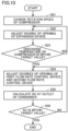
- Fig. 6 is a flowchart for describing control of controller 90 in the first operation mode.
- controller 90 changes the rotation speed of compressor 1 (step S1).
- the rotation speed of compressor 1 is determined according to, for example, a difference between the indoor temperature and the temperature set with a remote control for the indoor unit.
- Controller 90 changes the rotation speed of compressor 1 to an appropriate value.
- Controller 90 then adjusts the degree of opening of expansion device 3 (step S2).
- Controller 90 then calculates the degree of supercool (SC) at the outlet of first heat exchanger 10 that functions as a condenser (step S3).
- the degree of supercool at the outlet of first heat exchanger 10 can be calculated from, for example, the temperature at the outlet of first heat exchanger 10 and the pressure of first heat exchanger 10.
- a sensor that detects temperature and a sensor that detects pressure can be disposed in the refrigerant circuit as appropriate.
- Controller 90 determines whether the degree of supercool at the outlet of first heat exchanger 10 that functions as a condenser is within a target range (step S4). When determining that the degree of supercool at the outlet of first heat exchanger 10 is not within the target range, controller 90 adjusts the degree of opening of expansion device 3 again in step S2.
- controller 90 repeatedly adjusts the degree of opening of expansion device 3 in step S2 until the degree of supercool at the outlet of first heat exchanger 10 falls within the target range that is set for every rotation speed of compressor 1.
- the target range is a target value ⁇ a target error.
- controller 90 adjusts the degree of opening of first flow rate control device 51 (step S5).
- Controller 90 then calculates the degree of superheat (SH) at the outlet of third heat exchanger 30 that functions as an evaporator (step S6). At this time, controller 90 calculates the degree of superheat at the outlet portion of third heat exchanger 30 based on the temperature detected by first temperature sensor 71 and the temperature detected by second temperature sensor 72.
- Controller 90 determines whether the degree of superheat at the outlet of third heat exchanger 30 that functions as an evaporator is within the target range (step S7). When determining that the degree of superheat at the outlet of third heat exchanger 30 is not within the target value, controller 90 adjusts the degree of opening of first flow rate control device 51 again in step S5.
- controller 90 repeatedly adjusts the degree of opening of first flow rate control device 51 in step S5 until the degree of superheat at the outlet of third heat exchanger 30 falls within the target range that is set for every rotation speed of compressor 1.
- controller 90 ends the process.
- controller 90 may set the degree of opening of first flow rate control device 51 to zero to block the flow path, thereby allowing the gaseous refrigerant to flow to third heat exchanger 30. In this case, controller 90 checks whether the rotation speed of compressor 1 is within the prescribed rotation speed range every time the rotation speed of compressor 1 changes.
- controller 90 calculates the degree of superheat of third heat exchanger 30 based on a detected value of first temperature sensor 71 and a detected value of second temperature sensor 72 and adjusts the degree of opening of first flow rate control device 51, thereby controlling the degree of superheat of third heat exchanger 30.
- Fig. 7 is a flowchart for describing control of controller 90 in the second operation mode.
- controller 90 changes the rotation speed of compressor 1 as in the process of step S1 (step S11).
- controller 90 adjusts the degree of opening of expansion device 3 such that the discharge temperature of compressor 1 is within the target range (step S12).
- the discharge temperature of compressor 1 can be specified based on, for example, a detected value of the temperature sensor provided at the discharge portion of compressor 1.
- Controller 90 determines whether the discharge temperature of compressor 1 is within the target range (step S13). When determining that the discharge temperature of compressor 1 is not within the target range, controller 90 adjusts the degree of opening of expansion device 3 again in step S12.
- controller 90 adjusts the degree of opening of first flow rate control device 51 (step S14).
- Controller 90 then calculates the degree of supercool at the outlet of third heat exchanger 30 that functions as a condenser (step S15). At this time, controller 90 calculates the degree of supercool at the outlet portion of third heat exchanger 30 based on the temperature detected by first temperature sensor 71 and the temperature detected by third temperature sensor 73.
- Controller 90 determines whether the degree of supercool at the outlet of third heat exchanger 30 that functions as a condenser is within the target range that is set for every rotation speed of compressor 1 (step S16). When determining that the degree of supercool at the outlet of third heat exchanger 30 is not within the target range, controller 90 adjusts the degree of opening of first flow rate control device 51 again in step S 14.
- controller 90 repeatedly adjusts the degree of opening of first flow rate control device 51 in step S14 until the degree of supercool at the outlet of third heat exchanger 30 falls within the target range that is set for every rotation speed of compressor 1.
- controller 90 ends the process.
- controller 90 calculates the degree of supercool of third heat exchanger 30 based on the detected value of first temperature sensor 71 and the detected value of third temperature sensor 73 and adjusts the degree of opening of first flow rate control device 51, thereby controlling the degree of supercool of third heat exchanger 30.
- refrigeration cycle apparatus 100 has operation capability improved by flowing liquid refrigerant or gaseous refrigerant to third heat exchanger 30 on the downstream side according to its operation mode.
- Refrigeration cycle apparatus 100 can thus have improved efficiency of operating a refrigeration cycle in either the first operation mode or the second operation mode.
- refrigeration cycle apparatus 100 can have operating efficiency improved with the use of gas-liquid separator 6 when second heat exchanger 20 and third heat exchanger 30 on the outdoor unit side are caused to function as either an evaporator or a condenser.
- the effect of improving the efficiency of operating a refrigeration cycle can be improved when a zeotropic refrigerant mixture is used.
- Fig. 8 is a refrigerant circuit diagram showing a configuration of a refrigeration cycle apparatus 110 according to Embodiment 2.
- Refrigeration cycle apparatus 110 according to Embodiment 2 is different from refrigeration cycle apparatus 100 according to Embodiment 1 in the configuration of the switch device.
- Refrigeration cycle apparatus 110 according to Embodiment 2 includes a switch device 400 composed of a first three-way valve 45 and a second three-way valve 46.
- First three-way valve 45 is provided among fourth switch port P44, second heat exchanger 20, and first junction point a. First three-way valve 45 switches a target to be connected to fourth switch port P44 between second heat exchanger 20 and first junction point a.
- Second three-way valve 46 is provided among expansion device 3, second heat exchanger 20, and second junction point b. Second three-way valve 46 switches a target to be connected to expansion device 3 between second heat exchanger 20 and second junction point b.
- Controller 90 controls four-way valve 4, first three-way valve 45, and second three-way valve 46 such that the flow path indicated by the solid line in Fig. 8 is formed in the first operation mode.
- the refrigerant circulates through the refrigerant circuit in the same order as the order shown in Fig. 2 .
- controller 90 controls four-way valve 4 as shown in Fig. 3 and also switches the manner of connection of first three-way valve 45 and second three-way valve 46 to the manner indicated by the broken line in Fig. 8 .
- the refrigerant circulates through the refrigerant circuit in the same order as the order shown in Fig. 3 .
- First three-way valve 45 functions similarly to first check valve 41 and second check valve 42 of refrigeration cycle apparatus 100 according to Embodiment 1.
- Second three-way valve 46 functions similarly to third check valve 43 and fourth check valve 44 of refrigeration cycle apparatus 100 according of Embodiment 1.
- the first valve mechanism includes first three-way valve 45
- the second valve mechanism includes second three-way valve 46.
- the first valve mechanism according to Embodiment 1 includes first check valve 41 and second check valve 42.
- the first valve mechanism according to Embodiment 2 includes first three-way valve 45.
- the second valve mechanism according to Embodiment 1 includes third check valve 43 and fourth check valve 44.
- the second valve mechanism according to Embodiment 2 includes second three-way valve 46.
- Embodiment 2 can thus reduce the number of components compared with Embodiment 1.
- Fig. 9 is a refrigerant circuit diagram showing a configuration of a refrigeration cycle apparatus 120 according to Embodiment 3. Compared with refrigeration cycle apparatus 100 according to Embodiment 1, refrigeration cycle apparatus 120 according to Embodiment 3 further includes a second flow rate control device 52 and a fourth temperature sensor 74.
- Second flow rate control device 52 is provided between second junction point b and the side of gas-liquid separator 6 on which the refrigerant in liquid state is discharged.
- Fourth temperature sensor 74 is provided between second flow rate control device 52 and the side of gas-liquid separator 6 on which liquid refrigerant is discharged.
- controller 90 can more finely adjust the amount of gaseous refrigerant and the amount of liquid refrigerant discharged from gas-liquid separator 6.
- first temperature sensor 71 since the detection target of first temperature sensor 71 is a temperature of gaseous refrigerant, the temperature gradient of the zeotropic refrigerant mixture needs to be taken into account when the saturation temperature of liquid refrigerant is calculated using a detected value of first temperature sensor 71.
- the saturation temperature of the liquid refrigerant can be directly detected with fourth temperature sensor 74. This allows controller 90 to more accurately calculate a degree of supercool based on a detected value of third temperature sensor 73 and a detected value of fourth temperature sensor 74.
- Fig. 10 is a flowchart for describing control of controller 90 in the second operation mode according to Embodiment 3.
- the flowchart shown in Fig. 10 is different from the flowchart shown in Fig. 7 only in that step S24 is provided in place of step S14.
- steps S21 to S23 in Fig. 10 are the same as the processes of steps S11 to S13 in Fig. 7 , description of which will not be repeated.
- controller 90 adjusts the degrees of opening of first flow rate control device 51 and second flow rate control device 52.
- Controller 90 then calculates the degree of supercool at the outlet of third heat exchanger 30 that functions as a condenser (step S25). At this time, controller 90 calculates the degree of supercool at the outlet portion of third heat exchanger 30 based on the temperature detected by third temperature sensor 73 and the temperature detected by fourth temperature sensor 74. Thus, controller 90 can more accurately calculate a degree of supercool than when calculating the degree of supercool at the outlet portion of third heat exchanger 30 based on the temperature detected by first temperature sensor 71 and the temperature detected by third temperature sensor 73.
- Controller 90 determines whether the degree of supercool at the outlet of third heat exchanger 30 that functions as a condenser is within the target range that is set for every rotation speed of compressor 1 (step S26). When determining that the degree of supercool at the outlet of third heat exchanger 30 is not within the target range, controller 90 adjusts the degrees of opening of first flow rate control device 51 and second flow rate control device 52 again in step S24.
- controller 90 repeatedly adjusts the degrees of opening of first flow rate control device 51 and second flow rate control device 52 in step S24 until the degree of supercool at the outlet of third heat exchanger 30 falls within the target range that is set for every rotation speed of compressor 1.
- controller 90 ends the process.
- the first valve mechanism includes first check valve 41 and second check valve 42, and the second valve mechanism includes third check valve 43 and fourth check valve 44.
- the first valve mechanism may include first three-way valve 45
- the second valve mechanism may include second three-way valve 46.
- a refrigeration cycle apparatus includes a compressor (1), a first heat exchanger (10), a second heat exchanger (20), a third heat exchanger (30), an expansion device (3), a gas-liquid separator (6), a first flow rate control device (51), and a switch device (40) configured to switch a refrigerant circulation path between a first route corresponding to a first operation mode and a second route corresponding to a second operation mode.
- refrigerant flows in order of the compressor (1), the first heat exchanger (10), the expansion device (3), the second heat exchanger (20), and the gas-liquid separator (6), and then, the refrigerant in liquid state discharged from the gas-liquid separator (6) flows into the third heat exchanger (30), and the refrigerant in gaseous state discharged from the gas-liquid separator (6) joins, through the first flow rate control device (51), the refrigerant discharged from the third heat exchanger (30) at a first junction point (a).
- the refrigerant after joining at the first junction point (a) flows to the compressor (1).
- the refrigerant flows in order of the compressor (1), the second heat exchanger (20), and the gas-liquid separator (6), the refrigerant in gaseous state discharged from the gas-liquid separator (6) flows through the first flow rate control device (51) into the third heat exchanger (30), the refrigerant in liquid state discharged from the gas-liquid separator (6) joins the refrigerant discharged from the third heat exchanger (30) at a second junction point (b), and the refrigerant after joining at the second junction point (b) flows in order of the expansion device (3), the first heat exchanger (10), and the compressor (1).
- the efficiency of operating a refrigeration cycle can be improved in either the first operation mode or the second operation mode.
- the operating efficiency can be improved with the gas-liquid separator when the heat exchanger is caused to function as either an evaporator or a condenser.
- the efficiency of operating a refrigeration cycle can be improved when a zeotropic refrigerant mixture is used.
- the switch device (40) includes a four-way valve (4), a first valve mechanism (41, 42), and a second valve mechanism (43, 44).
- the four-way valve (4) has a first switch port (P41), a second switch port (P42), a third switch port (P43), and a fourth switch port (P44), an outlet port of the compressor (1) is connected to the first switch port (P41), and an inlet port of the compressor (1) is connected to the second switch port (P42).
- the four-way valve (4) is configured to, in the first operation mode, cause the first switch port (P41) to communicate with the third switch port (P43) and cause the second switch port (P42) to communicate with the fourth switch port (P44), and in the second operation mode, cause the first switch port (P41) to communicate with the fourth switch port (P44) and cause the second switch port (P42) to communicate with the third switch port (P43).
- the first valve mechanism (41, 42) is configured to, in the first operation mode, open a flow of the refrigerant from the first junction point (a) to the fourth switch port (P44) and interrupt a flow of the refrigerant from the expansion device (3) to the fourth switch port (P44), and in the second operation mode, open a flow of the refrigerant from the fourth switch port (P44) to the second heat exchanger (20) and interrupt a flow of the refrigerant from the fourth switch port (P44) to the first junction point (a).
- the second valve mechanism (43, 44) is configured to, in the first operation mode, open a flow of the refrigerant from the expansion device (3) to the second heat exchanger (20) and interrupt a flow of the refrigerant from the expansion device (3) to the second junction point (b), and in the second operation mode, open a flow of the refrigerant from the second junction point (b) to the expansion device (3) and interrupt a flow of the refrigerant from the fourth switch port (P44) to the expansion device (3).
- the first valve mechanism (41, 42) includes a first check valve (41) provided between the fourth switch port (P44) and the first junction point (a) and configured to interrupt a flow of the refrigerant from the fourth switch port (P44) toward a first junction point (a), and a second check valve (42) provided among the expansion device (3), the fourth switch port (P44), and the second heat exchanger (20) and configured to interrupt a flow of the refrigerant from the expansion device (3) to the fourth switch port (P44).
- a first check valve (41) provided between the fourth switch port (P44) and the first junction point (a) and configured to interrupt a flow of the refrigerant from the fourth switch port (P44) toward a first junction point (a)
- a second check valve (42) provided among the expansion device (3), the fourth switch port (P44), and the second heat exchanger (20) and configured to interrupt a flow of the refrigerant from the expansion device (3) to the fourth switch port (P44).
- the second valve mechanism (43, 44) includes a third check valve (43) provided among the fourth switch port (P44), the expansion device (3), and the second heat exchanger (20) and configured to interrupt a flow of the refrigerant from the fourth switch port (P44) to the expansion device (3), and a fourth check valve (44) provided between the expansion device and the second junction point (b) and configured to interrupt a flow of the refrigerant from the expansion device (3) to the second junction point (b).
- the first valve mechanism may include a first three-way valve (45).
- the second valve mechanism may include a second three-way valve (46).
- the first three-way valve (45) is provided among the fourth switch port (P44), the second heat exchanger (20), and the first junction point (a) and is configured to switch a target to be connected to the fourth switch port (P44) between the second heat exchanger (20) and the first junction point (a).
- the second three-way valve (46) is provided among the expansion device (3), the second heat exchanger (20), and the second junction point (b) and is configured to switch a target to be connected to the expansion device (3) between the second heat exchanger (20) and the second junction point (b).
- the refrigeration cycle apparatus further includes a first temperature sensor (71) provided between the first flow rate control device (51) and a side (P62) of the gas-liquid separator (6) on which the refrigerant in gaseous state is discharged, a second temperature sensor (72) provided between the third heat exchanger (30) and the first junction point (a), and a controller (90) configured to control the first flow rate control device (51).
- the controller (90) is configured to, in the first operation mode, calculate a degree of superheat of the third heat exchanger (30) based on a detected value of the first temperature sensor (71) and a detected value of the second temperature sensor (72) (step S6) and adjust a degree of opening of the first flow rate control device (51) to control the degree of superheat of the third heat exchanger (30) (step S5 to step S7).
- the refrigeration cycle apparatus may further include a third temperature sensor (73) provided between the third heat exchanger (30) and the second junction point (b).
- the controller (90) is configured to, in the second operation mode, calculate a degree of supercool of the third heat exchanger (30) based on a detected value of the first temperature sensor (71) and a detected value of the third temperature sensor (73) (step S15), and adjust the degree of opening of the first flow rate control device (51) to control the degree of supercool of the third heat exchanger (30) (step S14 to step S16).
- the refrigeration cycle apparatus may further include a second flow rate control device (52) provided between the second junction point (b) and a side (P63) of the gas-liquid separator (6) on which the refrigerant in liquid state is discharged, a third temperature sensor (73) provided between the third heat exchanger (30) and the second junction point (b), and a fourth temperature sensor (74) provided between the second flow rate control device (52) and a side (P63) of the gas-liquid separator (6) on which the refrigerant in liquid state is discharged.
- a second flow rate control device (52) provided between the second junction point (b) and a side (P63) of the gas-liquid separator (6) on which the refrigerant in liquid state is discharged
- a third temperature sensor (73) provided between the third heat exchanger (30) and the second junction point (b)
- a fourth temperature sensor (74) provided between the second flow rate control device (52) and a side (P63) of the gas-liquid separator (6) on which the refrigerant in liquid state is discharged
- the controller (90) is configured to, in the second operation mode, calculate a degree of supercool of the third heat exchanger (30) based on a detected value of the third temperature sensor (73) and a detected value of the fourth temperature sensor (74) (step S25), and adjust degrees of opening of the first flow rate control device (51) and the second flow rate control device (52) to control the degree of supercool of the third heat exchanger (30) (step S24 to step S26).
Landscapes
- Engineering & Computer Science (AREA)
- Physics & Mathematics (AREA)
- Mechanical Engineering (AREA)
- Thermal Sciences (AREA)
- General Engineering & Computer Science (AREA)
- Compression-Type Refrigeration Machines With Reversible Cycles (AREA)
Abstract
Description
- The present disclosure relates to a refrigeration cycle apparatus.
- In recent years, the development of a refrigeration cycle apparatus using a zeotropic refrigerant mixture has been pursued partly under the influence of a lowered regulation value of global warming potential (GWP).
Japanese Utility Model Publication No. 62-025644 - PTL 1:
Japanese Utility Model Publication No. 62-025644 - The technique described in
PTL 1 can improve the efficiency of operating a refrigeration cycle by separating the refrigerant into refrigerant in gaseous state and refrigerant in liquid state by the gas-liquid separator before guiding the refrigerant in liquid state to the second evaporator.PTL 1, however, discloses a technique of exclusively applying the gas-liquid separator to the evaporator. As a result, a system in which a heat exchanger is caused to function not only as an evaporator but also as a condenser fails to efficiently utilize such a technique. - The present disclosure has been made to solve the above problem. An object of the present disclosure is to provide a refrigeration cycle apparatus that can have operating efficiency improved with the use of a gas-liquid separator when a heat exchanger is caused to function as either an evaporator or a condenser.
- The present disclosure relates to a refrigeration cycle apparatus. The refrigeration cycle apparatus includes a compressor, a first heat exchanger, a second heat exchanger, a third heat exchanger, an expansion device, a gas-liquid separator, a first flow rate control device, and a switch device. The switch device is configured to switch a refrigerant circulation path between a first route corresponding to a first operation mode and a second route corresponding to a second operation mode. In the first route, refrigerant flows in order of the compressor, the first heat exchanger, the expansion device, the second heat exchanger, and the gas-liquid separator, the refrigerant in liquid state discharged from the gas-liquid separator flows into the third heat exchanger, the refrigerant in gaseous state discharged from the gas-liquid separator joins, through the first flow rate control device, the refrigerant discharged from the third heat exchanger at a first junction point, and the refrigerant after joining at the first junction point flows to the compressor. In the second route, the refrigerant flows in order of the compressor, the second heat exchanger, and the gas-liquid separator, the refrigerant in gaseous state discharged from the gas-liquid separator flows through the first flow rate control device into the third heat exchanger, the refrigerant in liquid state discharged from the gas-liquid separator joins the refrigerant discharged from the third heat exchanger at a second junction point, and the refrigerant after joining at the second junction point flows in order of the expansion device, the first heat exchanger, and the compressor.
- The refrigeration cycle apparatus according to the present disclosure can have operating efficiency improved with the use of the gas-liquid separator when the heat exchanger is caused to function as either an evaporator or a condenser.
-
-
Fig. 1 is a refrigerant circuit diagram showing a configuration of a refrigeration cycle apparatus (Embodiment 1). -
Fig. 2 shows a refrigerant flow in a first operation mode of the refrigeration cycle apparatus (Embodiment 1). -
Fig. 3 shows a refrigerant flow in a second operation mode of the refrigeration cycle apparatus (Embodiment 1). -
Fig. 4 is a p-h diagram showing changes in the state of refrigerant in the first operation mode (Embodiment 1). -
Fig. 5 is a p-h diagram showing changes in the state of refrigerant in the second operation mode (Embodiment 1). -
Fig. 6 is a flowchart for describing control of a controller in the first operation mode (Embodiment 1). -
Fig. 7 is a flowchart for describing control of the controller in the second operation mode (Embodiment 1). -
Fig. 8 is a refrigerant circuit diagram showing a configuration of a refrigeration cycle apparatus (Embodiment 2). -
Fig. 9 is a refrigerant circuit diagram showing a configuration of a refrigeration cycle apparatus (Embodiment 3). -
Fig. 10 is a flowchart for describing control of a controller in the second operation mode (Embodiment 3). - Embodiments of the present disclosure will be described below in detail with reference to the drawings. The same or corresponding parts will be designated by the same reference numerals, and description thereof will not be repeated.
-
Fig. 1 is a refrigerant circuit diagram showing a configuration of arefrigeration cycle apparatus 100 according toEmbodiment 1.Refrigeration cycle apparatus 100 includes a refrigerant circuit composed of at least acompressor 1, anexpansion device 3, a four-way valve 4, a gas-liquid separator 6, afirst heat exchanger 10, asecond heat exchanger 20, athird heat exchanger 30, a first flowrate control device 51, and acontroller 90. -
First heat exchanger 10 is mounted in an indoor unit.Second heat exchanger 20 andthird heat exchanger 30 are mounted in an outdoor unit. A gas-liquid separator 6 is disposed betweensecond heat exchanger 20 andthird heat exchanger 30. This configuration is equivalent to a configuration in which a heat exchanger on the outdoor unit side is divided into two heat exchangers, and gas-liquid separator 6 is disposed between one of the heat exchangers and the other heat exchanger. -
Second heat exchanger 20 has a first port P1 and a second port P2.Third heat exchanger 30 has a third port P3 and a fourth port P4. - Gas-
liquid separator 6 includes an inflow port P61, a gas discharge port P62, and a liquid discharge port P63. A first flowrate control device 51, which adjusts a flow rate of the refrigerant, is provided between gas discharge port P62 andthird heat exchanger 30. First flowrate control device 51 includes a valve for adjusting a flow rate of the refrigerant. First flowrate control device 51 adjusts a degree of opening of the valve to change a flow rate of the refrigerant. - The refrigerant discharged from second port P2 of
second heat exchanger 20 flows into inflow port P61. Gas discharge port P62 is connected via first flowrate control device 51 to third port P3 ofthird heat exchanger 30. Gas discharge port P62 discharges the refrigerant in gaseous state from gas-liquid separator 6. Liquid discharge port P63 is connected to fourth port P4 ofthird heat exchanger 30. Liquid discharge port P63 discharges the refrigerant in liquid state from gas-liquid separator 6. - Hereinbelow, the refrigerant in gaseous state is referred to as gaseous refrigerant, and the refrigerant in liquid state is referred to as liquid refrigerant. When it is not necessary to refer to whether the state of refrigerant is the gaseous state or the liquid state, the term "refrigerant" is merely used.
- Four-
way valve 4 has a first switch port P41, a second switch port P42, a third switch port P43, and a fourth switch port P44. An outlet port ofcompressor 1 is connected to first switch port P41, and an inlet port ofcompressor 1 is connected to second switch port P42. - The refrigerant circuit of
refrigeration cycle apparatus 100 is provided with afirst check valve 41, asecond check valve 42, athird check valve 43, and afourth check valve 44. -
First check valve 41 is provided between fourth switch port P44 of four-way valve 4 and a point a, shown inFig. 1 , on the refrigerant circuit. Point a corresponds to a first junction point at which the refrigerant discharged from third port P3 ofthird heat exchanger 30 joins the refrigerant discharged from first flowrate control device 51.First check valve 41 interrupts a flow of the refrigerant from fourth switch port P44 toward first junction point a. -
Second check valve 42 is provided between fourth switch port P44 of four-way valve 4 and first port P1 ofsecond heat exchanger 20.Second check valve 42 interrupts a flow of the refrigerant fromexpansion device 3 toward fourth switch port P44 of four-way valve 4. -
Third check valve 43 is provided among fourth switch port P44,expansion device 3, and first port P1 ofsecond heat exchanger 20.Third check valve 43 interrupts a flow of the refrigerant from the fourth switch port towardexpansion device 3. -
Fourth check valve 44 is provided betweenexpansion device 3 and a point b, shown inFig. 1 , on the refrigerant circuit. Point b corresponds to a second junction point at which the refrigerant discharged from fourth port P4 ofthird heat exchanger 30 joins the refrigerant discharged from liquid discharge port P63 of gas-liquid separator 6.Fourth check valve 44 interrupts a flow of the refrigerant fromexpansion device 3 to second junction point b. - Four-
way valve 4 changes between a first state and a second state. In the first state, first switch port P41 communicates with third switch port P43, and second switch port P42 communicates with fourth switch port P44. In the second state, first switch port P41 communicates with fourth switch port P44, and second switch port P42 communicates with third switch port P43. - Four-
way valve 4 changes between the first state and the second state, thus switching the direction in which the refrigerant discharged fromcompressor 1 flows through a flow path. As four-way valve 4,first check valve 41,second check valve 42,third check valve 43, andfourth check valve 44 function, the order in which the refrigerant circulates is switched between a first order and a second order. Thus, the operation mode ofrefrigeration cycle apparatus 100 is switched between the first operation mode and the second operation mode. - In the first operation mode, high-pressure refrigerant flows into
first heat exchanger 10. In the second operation mode, low-pressure refrigerant flows intofirst heat exchanger 10. Whenfirst heat exchanger 10 is mounted in the indoor unit, the first operation mode corresponds to a heating operation, and the second operation mode corresponds to a cooling operation.Controller 90 sets four-way valve 4 to the first state in the first operation mode and sets four-way valve 4 to the second state in the second operation mode. - Four-
way valve 4,first check valve 41,second check valve 42,third check valve 43, andfourth check valve 44 constituteswitch device 40 that switches the operation mode.Switch device 40 switches the route in which the refrigerant discharged fromcompressor 1 circulates between a first route corresponding to the first operation mode and a second route corresponding to the second operation mode. - The refrigerant circuit of
refrigeration cycle apparatus 100 is provided with a plurality of temperature sensors including afirst temperature sensor 71, asecond temperature sensor 72, and athird temperature sensor 73. -
First temperature sensor 71 is provided on the side of gas-liquid separator 6 on which the refrigerant in gaseous state is discharged. More specifically,first temperature sensor 71 is provided between first flowrate control device 51 and the side of gas-liquid separator 6 on which the refrigerant in gaseous state is discharged. -
Second temperature sensor 72 is provided on the third port P3 side ofthird heat exchanger 30. More specifically,second temperature sensor 72 is provided between first junction point a and the third port P3 side ofthird heat exchanger 30. -
Third temperature sensor 73 is provided on the fourth port P4 side ofthird heat exchanger 30. More specifically,third temperature sensor 73 is provided between second junction point b and the fourth port P4 side ofthird heat exchanger 30. -
Controller 90 includes aprocessor 91 and amemory 92.Memory 92 includes a Read Only Memory (ROM) and a Random Access Memory (RAM).Processor 91 deploys a program stored in the ROM to the RAM or the like and executes the program. The program stored in the ROM is a program in which a procedure ofcontroller 90 is described. -
Controller 90 controls each device inrefrigeration cycle apparatus 100 according to the program stored inmemory 92. For example,controller 90controls compressor 1,expansion device 3, four-way valve 4, and first flowrate control device 51. - Next, refrigerant flows in the first operation mode and the second operation mode will be described. In the present disclosure,
second heat exchanger 20 is located upstream of the refrigerant andthird heat exchanger 30 is located downstream of the refrigerant, wherecompressor 1 is a starting point, in either the first route or the second route, as apparent from the description below. - The present disclosure will be described by taking a zeotropic refrigerant mixture, such as R466A, as an example of the refrigerant. The zeotropic refrigerant mixture is obtained by mixing two or more types of refrigerant having different boiling points. Thus, the zeotropic refrigerant mixture is characterized by divergence that occurs between saturated gas temperature and saturated liquid temperature under constant pressure. The saturated gas temperature is usually higher than the saturated liquid temperature. Such a temperature difference is referred to as a temperature gradient.
- The presence of temperature gradient may cause an imbalance in the temperature in the heat exchanger, leading to reduced operating efficiency. The present disclosure proposes a configuration that can improve operating performance while reducing a pressure loss when the zeotropic refrigerant mixture is used. In particular, the present disclosure proposes a configuration applicable to either the first operation mode or the second operation mode.
- In
refrigeration cycle apparatus 100, the heat exchanger in the outdoor unit is divided intosecond heat exchanger 20 on the upstream side andthird heat exchanger 30 on the downstream side, and gas-liquid separator 6 is disposed in the flow path at some midpoint betweensecond heat exchanger 20 andthird heat exchanger 30. Inrefrigeration cycle apparatus 100, further, liquid refrigerant or gaseous refrigerant is flowed tothird heat exchanger 30 on the downstream side according to the operation mode, to thereby improve operating capability. The refrigerant applicable torefrigeration cycle apparatus 100 is not limited to the zeotropic refrigerant mixture. -
Fig. 2 shows a refrigerant flow in the first operation mode ofrefrigeration cycle apparatus 100. The refrigerant flow in the first operation mode will be described with reference toFig. 2 . In the first operation mode,controller 90 controls four-way valve 4 such that the flow path indicated by the solid line inFig. 2 is formed in four-way valve 4. - At this time, the refrigerant flows through the refrigerant circuit of
refrigeration cycle apparatus 100, as indicated by the arrows, by the action ofswitch device 40 including four-way valve 4. Specifically, the refrigerant discharged fromcompressor 1 flows through first switch port P41 and third switch port P43 of four-way valve 4 and then in order offirst heat exchanger 10,expansion device 3,second heat exchanger 20, and gas-liquid separator 6. Subsequently, the liquid refrigerant discharged from liquid discharge port P63 of gas-liquid separator 6 flows from fourth port P4 intothird heat exchanger 30. - On the other hand, the gaseous refrigerant discharged from gas discharge port P62 of gas-
liquid separator 6 flows through first flowrate control device 51 toward first junction point a shown inFig. 2 . The refrigerant discharged from third port P3 ofthird heat exchanger 30 also flows into first junction point a. The refrigerant after joining at first junction point a from two directions flows through four-way valve 4 into the inlet port ofcompressor 1. - As described above, the first route of the refrigerant in the first operation mode is formed by the route of the refrigerant outlined. In other words, in the first route, the refrigerant flows in order of
compressor 1,first heat exchanger 10,expansion device 3,second heat exchanger 20, and gas-liquid separator 6, and then, the refrigerant in liquid state discharged from gas-liquid separator 6 flows intothird heat exchanger 30, whereas the refrigerant in gaseous state discharged from gas-liquid separator 6 joins, through first flowrate control device 51, the refrigerant discharged fromthird heat exchanger 30 at first junction point a. The refrigerant after joining at first junction point a flows tocompressor 1. - Next, a refrigerant flow in the first operation mode will be described in more detail. In the first operation mode,
first heat exchanger 10 on the indoor unit side functions as a condenser, andsecond heat exchanger 20 andthird heat exchanger 30 on the outdoor unit side function as an evaporator. High-temperature, high-pressure gaseous refrigerant discharged fromcompressor 1 flows through four-way valve 4 and then intofirst heat exchanger 10 on the indoor unit side. - The gaseous refrigerant that has flowed into
first heat exchanger 10 condenses by heat dissipation to the indoor air. As a result, liquefaction of the refrigerant advances infirst heat exchanger 10. The refrigerant discharged fromfirst heat exchanger 10 flows intoexpansion device 3.Expansion device 3 includes a valve for adjusting a degree of expansion of the refrigerant. The refrigerant discharged fromfirst heat exchanger 10 expands inexpansion device 3 to turn into two-phase refrigerant that is a mixture of gas and liquid. - The two-phase refrigerant discharged from
expansion device 3 flows throughthird check valve 43 from first port P1 tosecond heat exchanger 20 on the outdoor unit side. A flow of the refrigerant fromexpansion device 3 toward second junction point b is interrupted byfourth check valve 44. - Since the two-phase refrigerant partly evaporates in
second heat exchanger 20, the two-phase refrigerant with an increased dryness fraction is discharged from second port P2 ofsecond heat exchanger 20. The two-phase refrigerant discharged from second port P2 flows from inflow port P61 into gas-liquid separator 6 to be separated into gaseous refrigerant and liquid refrigerant. - The liquid refrigerant separated in gas-
liquid separator 6 is discharged from liquid discharge port P63. The liquid refrigerant discharged from liquid discharge port P63 flows from fourth port P4 intothird heat exchanger 30. At this time, the liquid refrigerant discharged from liquid discharge port P63 does not flow throughfourth check valve 44 to theexpansion device 3 side. This is because the pressure of the liquid refrigerant discharged from liquid discharge port P63 is lower than the pressure of the refrigerant that flows fromexpansion device 3 towardthird check valve 43. The pressure difference therebetween corresponds to the amount of pressure loss betweensecond heat exchanger 20 andthird check valve 43. -
Third temperature sensor 73 detects the temperature of the liquid refrigerant that flows from fourth port P4 intothird heat exchanger 30. The temperature detected bythird temperature sensor 73 is transmitted tocontroller 90. - On the other hand, the gaseous refrigerant separated in gas-
liquid separator 6 is discharged from gas discharge port P62. The gaseous refrigerant discharged from gas discharge port P62 flows through first flowrate control device 51 toward first junction point a on the downstream side ofthird heat exchanger 30 without flowing intothird heat exchanger 30. Thus, ofsecond heat exchanger 20 andthird heat exchanger 30 in the outdoor unit, the liquid refrigerant flows, and the gaseous refrigerant does not flow, intothird heat exchanger 30 on the downstream side. -
First temperature sensor 71 detects the temperature of the gaseous refrigerant separated in gas-liquid separator 6. The temperature detected byfirst temperature sensor 71 is transmitted tocontroller 90. This temperature is equivalent to the saturated gas temperature of the refrigerant that has flowed into gas-liquid separator 6.Controller 90 estimates the pressure in gas-liquid separator 6 from the temperature detected byfirst temperature sensor 71. - In
third heat exchanger 30, the liquid refrigerant is subjected to heat exchange with the outside air to be gasified. Thus, since the gaseous refrigerant does not flow intothird heat exchanger 30, a temperature gradient does not occur inthird heat exchanger 30. Consequently, a temperature imbalance does not occur inthird heat exchanger 30. The refrigerant gasified inthird heat exchanger 30 is discharged from third port P3. -
Second temperature sensor 72 detects the temperature of the gaseous refrigerant discharged from third port P3. The temperature detected bysecond temperature sensor 72 is transmitted tocontroller 90. The temperature detected bysecond temperature sensor 72 corresponds to the temperature at the outlet of the evaporator in the first operation mode.Controller 90 estimates a degree of superheat (SH) at the outlet of the evaporator based on the temperature detected byfirst temperature sensor 71 and the temperature detected bysecond temperature sensor 72. - The gaseous refrigerant discharged from third port P3 of
third heat exchanger 30 joins the gaseous refrigerant discharged from first flowrate control device 51 at first junction point a. The gaseous refrigerant after joining from two directions flows throughfirst check valve 41 and four-way valve 4 into the inlet side ofcompressor 1. At this time, the gaseous refrigerant does not flow throughsecond check valve 42 tosecond heat exchanger 20. This is because the pressure of the gaseous refrigerant betweenfirst check valve 41 and four-way valve 4 is lower than the pressure of the refrigerant at first port P1 ofsecond heat exchanger 20. The pressure difference therebetween corresponds to the amount of pressure loss betweensecond heat exchanger 20 andfirst check valve 41. -
Fig. 3 shows a refrigerant flow in the second operation mode ofrefrigeration cycle apparatus 100. The refrigerant flow in the second operation mode will be described with reference toFig. 3 . In the second operation mode,controller 90 controls four-way valve 4 such that the flow path indicated by the solid line inFig. 3 is formed in four-way valve 4. - At this time, the refrigerant flows through the refrigerant circuit of
refrigeration cycle apparatus 100, as indicated by the arrows, by the action ofswitch device 40 including four-way valve 4. Specifically, the refrigerant discharged fromcompressor 1 flows through first switch port P41 and fourth switch port P44 of four-way valve 4, and then in order ofsecond heat exchanger 20 and gas-liquid separator 6. Subsequently, the gaseous refrigerant discharged from gas discharge port P62 of gas-liquid separator 6 flows through first flowrate control device 51 from third port P3 intothird heat exchanger 30. - On the other hand, the liquid refrigerant discharged from liquid discharge port P63 of gas-
liquid separator 6 joins the refrigerant discharged from fourth port P4 ofthird heat exchanger 30 at second junction point b. The refrigerant after joining at second junction point b flows in order ofexpansion device 3 andfirst heat exchanger 10, and then flows through four-way valve 4 into the inlet port ofcompressor 1. - As described above, the second route of the refrigerant in the second operation mode is formed by the route of the refrigerant outlined. In other words, in the second route, the refrigerant flows in order of
compressor 1,second heat exchanger 20, and gas-liquid separator 6, and the refrigerant in gaseous state discharged from gas-liquid separator 6 flows through first flowrate control device 51 intothird heat exchanger 30, whereas the refrigerant in liquid state discharged from gas-liquid separator 6 joins the refrigerant discharged fromthird heat exchanger 30 at second junction point b, and the refrigerant after joining at second junction point b flows in order ofexpansion device 3,first heat exchanger 10, andcompressor 1. - Next, a flow of the refrigerant in the second operation mode will be described in more detail. In the second operation mode,
first heat exchanger 10 on the indoor unit side functions as an evaporator, andsecond heat exchanger 20 andthird heat exchanger 30 on the outdoor unit side function as a condenser. High-temperature, high-pressure gaseous refrigerant discharged fromcompressor 1 flows through four-way valve 4, and then flows throughsecond check valve 42 from first port P1 intosecond heat exchanger 20 on the outdoor unit side. A flow of the refrigerant from four-way valve 4 toward first junction point a is interrupted byfirst check valve 41. - The gaseous refrigerant that has flowed into
second heat exchanger 20 condenses by heat dissipation to the outside air to turn into two-phase refrigerant that is a mixture of gas and liquid. The two-phase refrigerant discharged from the second port ofsecond heat exchanger 20 flows from inflow port P61 into gas-liquid separator 6 to be separated into gaseous refrigerant and liquid refrigerant. - The gaseous refrigerant separated in gas-
liquid separator 6 is discharged from gas discharge port P62. The gaseous refrigerant discharged from gas discharge port P62 flows through first flowrate control device 51 from third port P3 intothird heat exchanger 30. At this time, the gaseous refrigerant discharged from first flowrate control device 51 does not flow throughfirst check valve 41 to the fourth switch port P44 side of four-way valve 4. This is because the pressure of the gaseous refrigerant discharged from first flowrate control device 51 is lower than the pressure of the refrigerant at fourth switch port P44 of four-way valve 4. The pressure difference therebetween is equivalent to the amount of pressure loss between four-way valve 4 andfirst check valve 41. - On the other hand, the liquid refrigerant separated in gas-
liquid separator 6 is discharged from liquid discharge port P63. The liquid refrigerant discharged from liquid discharge port P63 flows downstream ofthird heat exchanger 30 without flowing intothird heat exchanger 30. Thus, ofsecond heat exchanger 20 andthird heat exchanger 30 in the outdoor unit, the gaseous refrigerant flows, and the liquid refrigerant does not flow, intothird heat exchanger 30 on the downstream side. - In
third heat exchanger 30, the gaseous refrigerant is subjected to heat exchange with the outside air to be condensed. As a result, the liquefaction of the refrigerant advances inthird heat exchanger 30. Thus, since the liquid refrigerant does not flow intothird heat exchanger 30, a temperature gradient does not occur inthird heat exchanger 30. Consequently, a temperature imbalance does not occur inthird heat exchanger 30. - The liquid refrigerant discharged from fourth port P4 of
third heat exchanger 30 joins the liquid refrigerant discharged from liquid discharge port P63 of gas-liquid separator 6 at second junction point b. The liquid refrigerant after joining at second junction point b flows throughfourth check valve 44 intoexpansion device 3. At this time, the liquid refrigerant does not flow throughthird check valve 43 tosecond heat exchanger 20. This is because the pressure of the refrigerant atfourth check valve 44 is lower than the pressure of the refrigerant at first port P1 ofsecond heat exchanger 20. The pressure difference therebetween is equivalent to the amount of pressure loss amongsecond heat exchanger 20, first flowrate control device 51, andfourth check valve 44. - The refrigerant that has flowed into
expansion device 3 is expanded byexpansion device 3, and then flows intofirst heat exchanger 10 on the indoor unit side. The refrigerant that has flowed intofirst heat exchanger 10 evaporates by heat absorption from the indoor air, and then flows through four-way valve 4 into the inlet side ofcompressor 1. - Flows of the refrigerant in the first operation mode and the second operation mode are as described above. In
refrigeration cycle apparatus 100,first check valve 41 andsecond check valve 42 constitute a first valve mechanism.Third check valve 43 andfourth check valve 44 constitute a second valve mechanism. - In the first operation mode where four-
way valve 4 is in the first state, the first valve mechanism causesexpansion device 3 to communicate with first port P1 ofsecond heat exchanger 20 and interrupts the communication betweenexpansion device 3 and fourth port P4 ofthird heat exchanger 30. - In the first operation mode, the first valve mechanism opens a flow of the refrigerant from first junction point a to fourth switch port P44 and interrupts a flow of the refrigerant from
expansion device 3 to fourth switch port P44. In the second operation mode, further, the first valve mechanism opens a flow of the refrigerant from fourth switch port P44 tosecond heat exchanger 20 and interrupts a flow of the refrigerant from fourth switch port P44 to first junction point a. - The second valve mechanism opens a flow of the refrigerant from
expansion device 3 tosecond heat exchanger 20 and interrupts a flow of the refrigerant fromexpansion device 3 to second junction point b in the first operation mode, and opens a flow of the refrigerant from second junction point b toexpansion device 3 and interrupts a flow of the refrigerant from fourth switch port P44 toexpansion device 3 in the second operation mode. -
Fig. 4 is a p-h diagram showing changes in the state of refrigerant in the first operation mode.Fig. 4 will be described with reference toFig. 2 . - Herein, hout, hout', hg, hl, hin, and hsep in
Fig. 4 correspond to Poout, Poout', Pog, Pol, Poin, and Posep inFig. 2 , respectively. For example, the enthalpy at a position Poin of the refrigerant circuit inFig. 2 corresponds to hin shown inFig. 4 . - High-temperature, high-pressure gaseous refrigerant discharged from
compressor 1 is condensed byfirst heat exchanger 10. Subsequently, the refrigerant is separated into two phases, that is, gaseous refrigerant and liquid refrigerant, inexpansion device 3, and then flows intosecond heat exchanger 20. The enthalpy of the refrigerant at this time is hin. The two-phase refrigerant with a higher dryness fraction is discharged fromsecond heat exchanger 20. The discharged two-phase refrigerant flows into gas-liquid separator 6. The enthalpy of the refrigerant at this time is hsep. - The two-phase refrigerant that has flowed into gas-
liquid separator 6 is separated into gaseous refrigerant and liquid refrigerant in gas-liquid separator 6. The gaseous refrigerant discharged from gas-liquid separator 6 flows toward first flowrate control device 51. The enthalpy of the gaseous refrigerant at this time is hg. On the other hand, the gaseous refrigerant discharged from gas-liquid separator 6 flows towardthird heat exchanger 30. The enthalpy of the liquid refrigerant at this time is hl. - Here, X = Y + Z holds, where X[kg/hr] is an amount of the refrigerant that flows into gas-
liquid separator 6, Y[kg/hr] is an amount of the gaseous refrigerant discharged from gas-liquid separator 6, and Z[kg/hr] is an amount of the liquid refrigerant discharged from gas-liquid separator 6. At this time, evaporation capacity is expressed by Equation (1) below.
- Here, a flow rate X depends on the rotation speed of
compressor 1, the density of the refrigerant suctioned intocompressor 1, and the like. A flow rate Y and a flow rate Z depend on the degree of opening of first flowrate control device 51 attached to the gaseous refrigerant outlet side of gas-liquid separator 6. An enthalpy hsep of the refrigerant that flows into gas-liquid separator 6 can be adjusted by the size, air volume, and the like ofsecond heat exchanger 20 that functions as an evaporator. Thus, evaporation capacity can be improved by adjusting the degree of opening of first flowrate control device 51 while taking into account changes in the composition of the refrigerant. - The liquid refrigerant that has flowed into
third heat exchanger 30 is subjected to heat exchange with the outside air to be gasified. Consequently, the enthalpy of the refrigerant discharged fromthird heat exchanger 30 is hout'. The gaseous refrigerant discharged fromthird heat exchanger 30 joins the gaseous refrigerant discharged from first flowrate control device 51 at junction point a. The enthalpy of the gaseous refrigerant at this time is hout. Subsequently, the gaseous refrigerant flows through four-way valve 4 back tocompressor 1. - In the first operation mode, only the liquid refrigerant is flowed to
third heat exchanger 30 with the use of gas-liquid separator 6. Thus, the flow rate of the refrigerant that flows tothird heat exchanger 30 can be reduced compared with the case where the total amount of two-phase refrigerant including gaseous refrigerant and liquid refrigerant is flowed to third heat exchanger 30 (Z = X - Y). As a result, a pressure loss can be reduced compared with the case where the total amount of two-phase refrigerant is flowed tothird heat exchanger 30. - In addition, since only the liquid refrigerant having a higher density than that of the gaseous refrigerant is flowed to
third heat exchanger 30, the dryness fraction at the inlet ofthird heat exchanger 30 is almost zero. Thus, the flow rate of the refrigerant that flows throughthird heat exchanger 30 can be reduced compared with the case where two-phase refrigerant is flowed. As a result, a pressure loss can be reduced also in terms of flow rate. - Considered here is a case where a plurality of flow paths are provided in
third heat exchanger 30 on the downstream side. In this case, when the two-phase zeotropic refrigerant mixture composed of gaseous refrigerant and liquid refrigerant is flowed tothird heat exchanger 30, the gaseous refrigerant flows through a flow path at a relatively high position, and the liquid refrigerant flows through a flow path at a relatively low position. This is because there is a density difference between the gaseous refrigerant and the liquid refrigerant. Then, an imbalance occurs in the refrigerant temperature due to the temperature gradient of the zeotropic refrigerant mixture. In the present embodiment, however, only the liquid refrigerant having an almost zero dryness fraction is flowed tothird heat exchanger 30. Such liquid refrigerant is insusceptible to gravity or a flow imbalance. Thus, the flow rate of the refrigerant in each flow path can be made uniform as only the liquid refrigerant is flowed tothird heat exchanger 30. As a result, the present embodiment can reduce an imbalance in the refrigerant temperature due to a temperature gradient. - The present embodiment can control the amount of the liquid refrigerant that flows through
third heat exchanger 30 by adjusting the degree of opening of first flowrate control device 51. For example, as the degree of opening of first flowrate control device 51 is increased with the rotation speed ofcompressor 1 and the degree of opening ofexpansion device 3 being kept constant, the amount of the gaseous refrigerant that is bypassed to the outlet side ofthird heat exchanger 30 that functions as an evaporator increases, and the amount of liquid refrigerant that flows throughthird heat exchanger 30 decreases. - It is expected that as the amount of the liquid refrigerant that flows through
third heat exchanger 30 decreases, the refrigerant will entirely evaporate withinthird heat exchanger 30 to be gasified. In this case, the degree of superheat at the outlet ofthird heat exchanger 30 increases. Contrastingly, as the degree of opening of first flowrate control device 51 is reduced, the amount of the liquid refrigerant that flows intothird heat exchanger 30 increases, so that the liquid refrigerant will not entirely gasify withinthird heat exchanger 30. As a result, the degree of superheat decreases. Thus, the degree of superheat at the outlet portion ofthird heat exchanger 30 can be controlled to an optimum value by adjusting the degree of opening of first flowrate control device 51 to increase or decrease the amount of gaseous refrigerant to be bypassed. - The degree of superheat at the outlet portion of
third heat exchanger 30 can be estimated based on the temperature detected byfirst temperature sensor 71 and the temperature detected bysecond temperature sensor 72. It is difficult to estimate a saturation temperature from the temperature of the refrigerant in two-phase state because the zeotropic refrigerant mixture has a temperature gradient, but the degree of superheat can be estimated more accurately based on the temperature of the gaseous refrigerant brought to a single-phase state by gas-liquid separator 6. -
Fig. 5 is a p-h diagram showing changes in the state of refrigerant in the second operation mode.Fig. 5 will be described with reference toFig. 3 . - Herein, hout, hout', hg, hl, hin, and hsep in
Fig. 5 correspond to Poout, Poout', Pog, Pol, Poin, and Posep inFig. 3 , respectively. - High-temperature, high-pressure gaseous refrigerant discharged from
compressor 1 flows intosecond heat exchanger 20. The enthalpy of the refrigerant at this time is hin. The refrigerant that has flowed intosecond heat exchanger 20 condenses to turn into two-phase refrigerant, and is then discharged. The two-phase refrigerant discharged fromsecond heat exchanger 20 flows into gas-liquid separator 6. The enthalpy of the refrigerant at this time is hsep. - The two-phase refrigerant that has flowed into gas-
liquid separator 6 is separated into gaseous refrigerant and liquid refrigerant in gas-liquid separator 6. The gaseous refrigerant discharged from gas-liquid separator 6 flows through first flowrate control device 51 towardthird heat exchanger 30. The enthalpy of the gaseous refrigerant upstream of first flowrate control device 51 is hg. On the other hand, the liquid refrigerant discharged from gas-liquid separator 6 flows downstream ofthird heat exchanger 30. The enthalpy of the liquid refrigerant at this time is hl. - Herein, X = Y + Z holds as in the case of the first operation mode, where X[kg/hr] is an amount of refrigerant that flows into gas-
liquid separator 6, Y[kg/hr] is an amount of gaseous refrigerant discharged from gas-liquid separator 6, and Z[kg/hr] is an amount of liquid refrigerant discharged from gas-liquid separator 6. At this time, condensation capacity is expressed by Equation (2) below.
- The gaseous refrigerant that has flowed into
third heat exchanger 30 is subjected to heat exchange with the outside air to be condensed. As a result, the enthalpy of the refrigerant discharged fromthird heat exchanger 30 is hout'. The refrigerant discharged fromthird heat exchanger 30 joins the liquid refrigerant discharged from gas-liquid separator 6 at second junction point b. The enthalpy of the refrigerant at this time is hout. Subsequently, the refrigerant expands inexpansion device 3, flows intofirst heat exchanger 10, evaporates, and then flows through four-way valve 4 back tocompressor 1. - In the second operation mode, only the gaseous refrigerant is flowed to
third heat exchanger 30 with the use of gas-liquid separator 6. Thus, the flow rate of the refrigerant that flows tothird heat exchanger 30 can be reduced compared with the case where the total amount of the two-phase refrigerant including gaseous refrigerant and liquid refrigerant is flowed tothird heat exchanger 30. As a result, a pressure loss can be reduced compared with the case where the total amount of the two-phase refrigerant is flowed tothird heat exchanger 30. - In the second operation mode, when the zeotropic refrigerant mixture flows into
second heat exchanger 20 on the outdoor unit side, refrigerant having a higher boiling point is condensed preferentially insecond heat exchanger 20 over refrigerant having a lower boiling point. Thus, the gaseous refrigerant in gas-liquid separator 6 is mostly refrigerant containing low-boiling components, and the liquid refrigerant in gas-liquid separator 6 is mostly refrigerant having a high boiling point. In the second operation mode, since only the gaseous refrigerant separated in gas-liquid separator 6 is flowed tothird heat exchanger 30, it is refrigerant containing low-boiling components that is condensed inthird heat exchanger 30. - Thus, in the second operation mode, the use of gas-
liquid separator 6 allows refrigerant containing more low-boiling components to flow tothird heat exchanger 30 on the downstream side, ofsecond heat exchanger 20 andthird heat exchanger 30. Herein, if the theoretical coefficient of performance of the refrigerant containing low-boiling components is higher than that of the refrigerant containing high-boiling components, the efficiency of the refrigeration cycle can be improved. - Also in the second operation mode, the amount of the refrigerant that flows to
third heat exchanger 30 can be adjusted by adjusting the degree of opening of first flowrate control device 51 while taking into account changes in the composition of the refrigerant, as in the first operation mode. For example, when the degree of opening of first flowrate control device 51 is increased with the rotation speed ofcompressor 1 and the degree of opening ofexpansion device 3 being kept constant, the amount of gaseous refrigerant that flows intothird heat exchanger 30 increases. - An increase in the amount of the gaseous refrigerant that flows to
third heat exchanger 30 leads to a higher liquid level in gas-liquid separator 6. As a result, the degree of supercool (SC) at the outlet portion ofthird heat exchanger 30 decreases. On the other hand, reducing the degree of opening of first flowrate control device 51 increases the degree of supercool. Thus, the degree of supercool at the outlet portion ofthird heat exchanger 30 can be controlled to an optimum value by adjusting the degree of opening of first flowrate control device 51 to increase or reduce the amount of the gaseous refrigerant that flows tothird heat exchanger 30. - The degree of supercool at the outlet portion of
third heat exchanger 30 can be estimated based on the temperature detected byfirst temperature sensor 71 and the temperature detected bythird temperature sensor 73. -
Fig. 6 is a flowchart for describing control ofcontroller 90 in the first operation mode. First,controller 90 changes the rotation speed of compressor 1 (step S1). The rotation speed ofcompressor 1 is determined according to, for example, a difference between the indoor temperature and the temperature set with a remote control for the indoor unit.Controller 90 changes the rotation speed ofcompressor 1 to an appropriate value. -
Controller 90 then adjusts the degree of opening of expansion device 3 (step S2). -
Controller 90 then calculates the degree of supercool (SC) at the outlet offirst heat exchanger 10 that functions as a condenser (step S3). The degree of supercool at the outlet offirst heat exchanger 10 can be calculated from, for example, the temperature at the outlet offirst heat exchanger 10 and the pressure offirst heat exchanger 10. Thus, a sensor that detects temperature and a sensor that detects pressure can be disposed in the refrigerant circuit as appropriate. -
Controller 90 then determines whether the degree of supercool at the outlet offirst heat exchanger 10 that functions as a condenser is within a target range (step S4). When determining that the degree of supercool at the outlet offirst heat exchanger 10 is not within the target range,controller 90 adjusts the degree of opening ofexpansion device 3 again in step S2. - Thus,
controller 90 repeatedly adjusts the degree of opening ofexpansion device 3 in step S2 until the degree of supercool at the outlet offirst heat exchanger 10 falls within the target range that is set for every rotation speed ofcompressor 1. Herein, the target range is a target value ± a target error. - When the degree of supercool at the outlet of
first heat exchanger 10 is within the target range in step S4,controller 90 adjusts the degree of opening of first flow rate control device 51 (step S5). -
Controller 90 then calculates the degree of superheat (SH) at the outlet ofthird heat exchanger 30 that functions as an evaporator (step S6). At this time,controller 90 calculates the degree of superheat at the outlet portion ofthird heat exchanger 30 based on the temperature detected byfirst temperature sensor 71 and the temperature detected bysecond temperature sensor 72. -
Controller 90 then determines whether the degree of superheat at the outlet ofthird heat exchanger 30 that functions as an evaporator is within the target range (step S7). When determining that the degree of superheat at the outlet ofthird heat exchanger 30 is not within the target value,controller 90 adjusts the degree of opening of first flowrate control device 51 again in step S5. - Thus,
controller 90 repeatedly adjusts the degree of opening of first flowrate control device 51 in step S5 until the degree of superheat at the outlet ofthird heat exchanger 30 falls within the target range that is set for every rotation speed ofcompressor 1. When determining that the degree of superheat at the outlet ofthird heat exchanger 30 is within the target range,controller 90 ends the process. - When the rotation speed of
compressor 1 is within a prescribed rotation speed range,controller 90 may set the degree of opening of first flowrate control device 51 to zero to block the flow path, thereby allowing the gaseous refrigerant to flow tothird heat exchanger 30. In this case,controller 90 checks whether the rotation speed ofcompressor 1 is within the prescribed rotation speed range every time the rotation speed ofcompressor 1 changes. - As described above with reference to the flowchart shown in
Fig. 6 , in the first operation mode,controller 90 calculates the degree of superheat ofthird heat exchanger 30 based on a detected value offirst temperature sensor 71 and a detected value ofsecond temperature sensor 72 and adjusts the degree of opening of first flowrate control device 51, thereby controlling the degree of superheat ofthird heat exchanger 30. -
Fig. 7 is a flowchart for describing control ofcontroller 90 in the second operation mode. First,controller 90 changes the rotation speed ofcompressor 1 as in the process of step S1 (step S11). - When changing the rotation speed of
compressor 1,controller 90 adjusts the degree of opening ofexpansion device 3 such that the discharge temperature ofcompressor 1 is within the target range (step S12). The discharge temperature ofcompressor 1 can be specified based on, for example, a detected value of the temperature sensor provided at the discharge portion ofcompressor 1.Controller 90 then determines whether the discharge temperature ofcompressor 1 is within the target range (step S13). When determining that the discharge temperature ofcompressor 1 is not within the target range,controller 90 adjusts the degree of opening ofexpansion device 3 again in step S12. - When determining that the discharge temperature of
compressor 1 is within the target range instep S 13,controller 90 adjusts the degree of opening of first flow rate control device 51 (step S14). -
Controller 90 then calculates the degree of supercool at the outlet ofthird heat exchanger 30 that functions as a condenser (step S15). At this time,controller 90 calculates the degree of supercool at the outlet portion ofthird heat exchanger 30 based on the temperature detected byfirst temperature sensor 71 and the temperature detected bythird temperature sensor 73. -
Controller 90 then determines whether the degree of supercool at the outlet ofthird heat exchanger 30 that functions as a condenser is within the target range that is set for every rotation speed of compressor 1 (step S16). When determining that the degree of supercool at the outlet ofthird heat exchanger 30 is not within the target range,controller 90 adjusts the degree of opening of first flowrate control device 51 again instep S 14. - Thus,
controller 90 repeatedly adjusts the degree of opening of first flowrate control device 51 in step S14 until the degree of supercool at the outlet ofthird heat exchanger 30 falls within the target range that is set for every rotation speed ofcompressor 1. When determining that the degree of supercool at the outlet ofthird heat exchanger 30 is within the target range,controller 90 ends the process. - As described above with reference to the flowchart shown in
Fig. 7 , in the second operation mode,controller 90 calculates the degree of supercool ofthird heat exchanger 30 based on the detected value offirst temperature sensor 71 and the detected value ofthird temperature sensor 73 and adjusts the degree of opening of first flowrate control device 51, thereby controlling the degree of supercool ofthird heat exchanger 30. - As described above,
refrigeration cycle apparatus 100 according toEmbodiment 1 has operation capability improved by flowing liquid refrigerant or gaseous refrigerant tothird heat exchanger 30 on the downstream side according to its operation mode.Refrigeration cycle apparatus 100 can thus have improved efficiency of operating a refrigeration cycle in either the first operation mode or the second operation mode. In other words,refrigeration cycle apparatus 100 can have operating efficiency improved with the use of gas-liquid separator 6 whensecond heat exchanger 20 andthird heat exchanger 30 on the outdoor unit side are caused to function as either an evaporator or a condenser. In particular, the effect of improving the efficiency of operating a refrigeration cycle can be improved when a zeotropic refrigerant mixture is used. - Next, Embodiment 2 will be described with reference to
Fig. 8. Fig. 8 is a refrigerant circuit diagram showing a configuration of arefrigeration cycle apparatus 110 according to Embodiment 2.Refrigeration cycle apparatus 110 according to Embodiment 2 is different fromrefrigeration cycle apparatus 100 according toEmbodiment 1 in the configuration of the switch device.Refrigeration cycle apparatus 110 according to Embodiment 2 includes aswitch device 400 composed of a first three-way valve 45 and a second three-way valve 46. - First three-
way valve 45 is provided among fourth switch port P44,second heat exchanger 20, and first junction point a. First three-way valve 45 switches a target to be connected to fourth switch port P44 betweensecond heat exchanger 20 and first junction point a. - Second three-
way valve 46 is provided amongexpansion device 3,second heat exchanger 20, and second junction point b. Second three-way valve 46 switches a target to be connected toexpansion device 3 betweensecond heat exchanger 20 and second junction point b. -
Controller 90 controls four-way valve 4, first three-way valve 45, and second three-way valve 46 such that the flow path indicated by the solid line inFig. 8 is formed in the first operation mode. As a result, the refrigerant circulates through the refrigerant circuit in the same order as the order shown inFig. 2 . In the second operation mode,controller 90 controls four-way valve 4 as shown inFig. 3 and also switches the manner of connection of first three-way valve 45 and second three-way valve 46 to the manner indicated by the broken line inFig. 8 . Thus, the refrigerant circulates through the refrigerant circuit in the same order as the order shown inFig. 3 . - First three-
way valve 45 functions similarly tofirst check valve 41 andsecond check valve 42 ofrefrigeration cycle apparatus 100 according toEmbodiment 1. Second three-way valve 46 functions similarly tothird check valve 43 andfourth check valve 44 ofrefrigeration cycle apparatus 100 according ofEmbodiment 1. In Embodiment 2, thus, the first valve mechanism includes first three-way valve 45, and the second valve mechanism includes second three-way valve 46. - The first valve mechanism according to
Embodiment 1 includesfirst check valve 41 andsecond check valve 42. On the other hand, the first valve mechanism according to Embodiment 2 includes first three-way valve 45. The second valve mechanism according toEmbodiment 1 includesthird check valve 43 andfourth check valve 44. On the other hand, the second valve mechanism according to Embodiment 2 includes second three-way valve 46. Embodiment 2 can thus reduce the number of components compared withEmbodiment 1. -
Fig. 9 is a refrigerant circuit diagram showing a configuration of arefrigeration cycle apparatus 120 according toEmbodiment 3. Compared withrefrigeration cycle apparatus 100 according toEmbodiment 1,refrigeration cycle apparatus 120 according toEmbodiment 3 further includes a second flowrate control device 52 and afourth temperature sensor 74. - Second flow
rate control device 52 is provided between second junction point b and the side of gas-liquid separator 6 on which the refrigerant in liquid state is discharged.Fourth temperature sensor 74 is provided between second flowrate control device 52 and the side of gas-liquid separator 6 on which liquid refrigerant is discharged. - Thus, as the mechanism that can adjust the flow rate is provided also in the portion to which liquid refrigerant is discharged from gas-
liquid separator 6,controller 90 can more finely adjust the amount of gaseous refrigerant and the amount of liquid refrigerant discharged from gas-liquid separator 6. - In addition, since the detection target of
first temperature sensor 71 is a temperature of gaseous refrigerant, the temperature gradient of the zeotropic refrigerant mixture needs to be taken into account when the saturation temperature of liquid refrigerant is calculated using a detected value offirst temperature sensor 71. Inrefrigeration cycle apparatus 120 according toEmbodiment 3, however, the saturation temperature of the liquid refrigerant can be directly detected withfourth temperature sensor 74. This allowscontroller 90 to more accurately calculate a degree of supercool based on a detected value ofthird temperature sensor 73 and a detected value offourth temperature sensor 74. -
Fig. 10 is a flowchart for describing control ofcontroller 90 in the second operation mode according toEmbodiment 3. The flowchart shown inFig. 10 is different from the flowchart shown inFig. 7 only in that step S24 is provided in place of step S14. - The processes of steps S21 to S23 in
Fig. 10 are the same as the processes of steps S11 to S13 inFig. 7 , description of which will not be repeated. - In step S24,
controller 90 adjusts the degrees of opening of first flowrate control device 51 and second flowrate control device 52. -
Controller 90 then calculates the degree of supercool at the outlet ofthird heat exchanger 30 that functions as a condenser (step S25). At this time,controller 90 calculates the degree of supercool at the outlet portion ofthird heat exchanger 30 based on the temperature detected bythird temperature sensor 73 and the temperature detected byfourth temperature sensor 74. Thus,controller 90 can more accurately calculate a degree of supercool than when calculating the degree of supercool at the outlet portion ofthird heat exchanger 30 based on the temperature detected byfirst temperature sensor 71 and the temperature detected bythird temperature sensor 73. -
Controller 90 then determines whether the degree of supercool at the outlet ofthird heat exchanger 30 that functions as a condenser is within the target range that is set for every rotation speed of compressor 1 (step S26). When determining that the degree of supercool at the outlet ofthird heat exchanger 30 is not within the target range,controller 90 adjusts the degrees of opening of first flowrate control device 51 and second flowrate control device 52 again in step S24. - Thus,
controller 90 repeatedly adjusts the degrees of opening of first flowrate control device 51 and second flowrate control device 52 in step S24 until the degree of supercool at the outlet ofthird heat exchanger 30 falls within the target range that is set for every rotation speed ofcompressor 1. When determining that the degree of supercool at the outlet ofthird heat exchanger 30 is within the target range,controller 90 ends the process. - In
Embodiment 3, the first valve mechanism includesfirst check valve 41 andsecond check valve 42, and the second valve mechanism includesthird check valve 43 andfourth check valve 44. However, the first valve mechanism may include first three-way valve 45, and the second valve mechanism may include second three-way valve 46. - The present embodiments will be summarized as follows.
- (1) The present disclosure relates to a refrigeration cycle apparatus. A refrigeration cycle apparatus (100) includes a compressor (1), a first heat exchanger (10), a second heat exchanger (20), a third heat exchanger (30), an expansion device (3), a gas-liquid separator (6), a first flow rate control device (51), and a switch device (40) configured to switch a refrigerant circulation path between a first route corresponding to a first operation mode and a second route corresponding to a second operation mode. In the first route, refrigerant flows in order of the compressor (1), the first heat exchanger (10), the expansion device (3), the second heat exchanger (20), and the gas-liquid separator (6), and then, the refrigerant in liquid state discharged from the gas-liquid separator (6) flows into the third heat exchanger (30), and the refrigerant in gaseous state discharged from the gas-liquid separator (6) joins, through the first flow rate control device (51), the refrigerant discharged from the third heat exchanger (30) at a first junction point (a). The refrigerant after joining at the first junction point (a) flows to the compressor (1). In the second route, the refrigerant flows in order of the compressor (1), the second heat exchanger (20), and the gas-liquid separator (6), the refrigerant in gaseous state discharged from the gas-liquid separator (6) flows through the first flow rate control device (51) into the third heat exchanger (30), the refrigerant in liquid state discharged from the gas-liquid separator (6) joins the refrigerant discharged from the third heat exchanger (30) at a second junction point (b), and the refrigerant after joining at the second junction point (b) flows in order of the expansion device (3), the first heat exchanger (10), and the compressor (1).
- With such a configuration, the efficiency of operating a refrigeration cycle can be improved in either the first operation mode or the second operation mode. In other words, the operating efficiency can be improved with the gas-liquid separator when the heat exchanger is caused to function as either an evaporator or a condenser. In particular, the efficiency of operating a refrigeration cycle can be improved when a zeotropic refrigerant mixture is used.
- (2) The switch device (40) includes a four-way valve (4), a first valve mechanism (41, 42), and a second valve mechanism (43, 44). The four-way valve (4) has a first switch port (P41), a second switch port (P42), a third switch port (P43), and a fourth switch port (P44), an outlet port of the compressor (1) is connected to the first switch port (P41), and an inlet port of the compressor (1) is connected to the second switch port (P42). The four-way valve (4) is configured to, in the first operation mode, cause the first switch port (P41) to communicate with the third switch port (P43) and cause the second switch port (P42) to communicate with the fourth switch port (P44), and in the second operation mode, cause the first switch port (P41) to communicate with the fourth switch port (P44) and cause the second switch port (P42) to communicate with the third switch port (P43). The first valve mechanism (41, 42) is configured to, in the first operation mode, open a flow of the refrigerant from the first junction point (a) to the fourth switch port (P44) and interrupt a flow of the refrigerant from the expansion device (3) to the fourth switch port (P44), and in the second operation mode, open a flow of the refrigerant from the fourth switch port (P44) to the second heat exchanger (20) and interrupt a flow of the refrigerant from the fourth switch port (P44) to the first junction point (a). The second valve mechanism (43, 44) is configured to, in the first operation mode, open a flow of the refrigerant from the expansion device (3) to the second heat exchanger (20) and interrupt a flow of the refrigerant from the expansion device (3) to the second junction point (b), and in the second operation mode, open a flow of the refrigerant from the second junction point (b) to the expansion device (3) and interrupt a flow of the refrigerant from the fourth switch port (P44) to the expansion device (3).
- (3) The first valve mechanism (41, 42) includes a first check valve (41) provided between the fourth switch port (P44) and the first junction point (a) and configured to interrupt a flow of the refrigerant from the fourth switch port (P44) toward a first junction point (a), and a second check valve (42) provided among the expansion device (3), the fourth switch port (P44), and the second heat exchanger (20) and configured to interrupt a flow of the refrigerant from the expansion device (3) to the fourth switch port (P44). The second valve mechanism (43, 44) includes a third check valve (43) provided among the fourth switch port (P44), the expansion device (3), and the second heat exchanger (20) and configured to interrupt a flow of the refrigerant from the fourth switch port (P44) to the expansion device (3), and a fourth check valve (44) provided between the expansion device and the second junction point (b) and configured to interrupt a flow of the refrigerant from the expansion device (3) to the second junction point (b).
- (4) The first valve mechanism may include a first three-way valve (45). The second valve mechanism may include a second three-way valve (46). The first three-way valve (45) is provided among the fourth switch port (P44), the second heat exchanger (20), and the first junction point (a) and is configured to switch a target to be connected to the fourth switch port (P44) between the second heat exchanger (20) and the first junction point (a). The second three-way valve (46) is provided among the expansion device (3), the second heat exchanger (20), and the second junction point (b) and is configured to switch a target to be connected to the expansion device (3) between the second heat exchanger (20) and the second junction point (b).
- (5) The refrigeration cycle apparatus further includes a first temperature sensor (71) provided between the first flow rate control device (51) and a side (P62) of the gas-liquid separator (6) on which the refrigerant in gaseous state is discharged, a second temperature sensor (72) provided between the third heat exchanger (30) and the first junction point (a), and a controller (90) configured to control the first flow rate control device (51). The controller (90) is configured to, in the first operation mode, calculate a degree of superheat of the third heat exchanger (30) based on a detected value of the first temperature sensor (71) and a detected value of the second temperature sensor (72) (step S6) and adjust a degree of opening of the first flow rate control device (51) to control the degree of superheat of the third heat exchanger (30) (step S5 to step S7).
- (6) The refrigeration cycle apparatus may further include a third temperature sensor (73) provided between the third heat exchanger (30) and the second junction point (b). The controller (90) is configured to, in the second operation mode, calculate a degree of supercool of the third heat exchanger (30) based on a detected value of the first temperature sensor (71) and a detected value of the third temperature sensor (73) (step S15), and adjust the degree of opening of the first flow rate control device (51) to control the degree of supercool of the third heat exchanger (30) (step S14 to step S16).
- (7) The refrigeration cycle apparatus may further include a second flow rate control device (52) provided between the second junction point (b) and a side (P63) of the gas-liquid separator (6) on which the refrigerant in liquid state is discharged, a third temperature sensor (73) provided between the third heat exchanger (30) and the second junction point (b), and a fourth temperature sensor (74) provided between the second flow rate control device (52) and a side (P63) of the gas-liquid separator (6) on which the refrigerant in liquid state is discharged. The controller (90) is configured to, in the second operation mode, calculate a degree of supercool of the third heat exchanger (30) based on a detected value of the third temperature sensor (73) and a detected value of the fourth temperature sensor (74) (step S25), and adjust degrees of opening of the first flow rate control device (51) and the second flow rate control device (52) to control the degree of supercool of the third heat exchanger (30) (step S24 to step S26).
- It should be understood that the embodiments disclosed herein have been presented for the purpose of illustration and non-restrictive in every respect. It is therefore intended that the scope of the present disclosure is defined by claims, not only by the embodiments described above, and encompasses all modifications and variations equivalent in meaning and scope to the claims.
- 1 compressor; 3 expansion device; 4 four-way valve; 6 gas-liquid separator; 10 first heat exchanger; 20 second heat exchanger; 30 third heat exchanger; 40 switch device; 41 first check valve; 42 second check valve; 43 third check valve; 44 fourth check valve; 45 first three-way valve; 46 second three-way valve; 51 first flow rate control device; 52 second flow rate control device; 71 first temperature sensor; 72 second temperature sensor; 73 third temperature sensor; 74 fourth temperature sensor; 90 controller; 91 processor; 92 memory; 100, 110, 120 refrigeration cycle apparatus; 400 switch device; P1 first port; P2 second port; P3 third port; P4 fourth port; P41 first switch port; P42 second switch port; P43 third switch port; P44 fourth switch port; P61 inflow port; P62 gas discharge port; P63 liquid discharge port.
Claims (7)
- A refrigeration cycle apparatus comprising:a compressor;a first heat exchanger;a second heat exchanger;a third heat exchanger;an expansion device;a gas-liquid separator;a first flow rate control device; anda switch device configured to switch a refrigerant circulation path between a first route corresponding to a first operation mode and a second route corresponding to a second operation mode, whereinin the first route,refrigerant flows in order of the compressor, the first heat exchanger, the expansion device, the second heat exchanger, and the gas-liquid separator,the refrigerant in liquid state discharged from the gas-liquid separator flows into the third heat exchanger,the refrigerant in gaseous state discharged from the gas-liquid separator joins, through the first flow rate control device, the refrigerant discharged from the third heat exchanger at a first junction point, andthe refrigerant after joining at the first junction point flows to the compressor, andin the second route,the refrigerant flows in order of the compressor, the second heat exchanger, and the gas-liquid separator,the refrigerant in gaseous state discharged from the gas-liquid separator flows through the first flow rate control device into the third heat exchanger,the refrigerant in liquid state discharged from the gas-liquid separator joins the refrigerant discharged from the third heat exchanger at a second junction point, andthe refrigerant after joining at the second junction point flows in order of the expansion device, the first heat exchanger, and the compressor.
- The refrigeration cycle apparatus according to claim 1, whereinthe switch device comprisesa four-way valve,a first valve mechanism, anda second valve mechanism,the four-way valve has a first switch port, a second switch port, a third switch port, and a fourth switch port, an outlet port of the compressor is connected to the first switch port, and an inlet port of the compressor is connected to the second switch port,the four-way valve is configured toin the first operation mode, cause the first switch port to communicate with the third switch port and cause the second switch port to communicate with the fourth switch port, andin the second operation mode, cause the first switch port to communicate with the fourth switch port and cause the second switch port to communicate with the third switch port,the first valve mechanism is configured toin the first operation mode, open a flow of the refrigerant from the first junction point to the fourth switch port and interrupt a flow of the refrigerant from the expansion device to the fourth switch port, andin the second operation mode, open a flow of the refrigerant from the fourth switch port to the second heat exchanger and interrupt a flow of the refrigerant from the fourth switch port to the first junction point, andthe second valve mechanism is configured toin the first operation mode, open a flow of the refrigerant from the expansion device to the second heat exchanger and interrupt a flow of the refrigerant from the expansion device to the second junction point, andin the second operation mode, open a flow of the refrigerant from the second junction point to the expansion device and interrupt a flow of the refrigerant from the fourth switch port to the expansion device.
- The refrigeration cycle apparatus according to claim 2, whereinthe first valve mechanism comprisesa first check valve provided between the fourth switch port and the first junction point and configured to interrupt a flow of the refrigerant from the fourth switch port toward the first junction point, anda second check valve provided among the expansion device, the fourth switch port, and the second heat exchanger and configured to interrupt the flow of the refrigerant from the expansion device to the fourth switch port, andthe second valve mechanism comprisesa third check valve provided among the fourth switch port, the expansion device, and the second heat exchanger and configured to interrupt the flow of the refrigerant from the fourth switch port to the expansion device, anda fourth check valve provided between the expansion device and the second junction point and configured to interrupt the flow of the refrigerant from the expansion device to the second junction point.
- The refrigeration cycle apparatus according to claim 2, whereinthe first valve mechanism comprises a first three-way valve,the second valve mechanism comprises a second three-way valve,the first three-way valve is provided among the fourth switch port, the second heat exchanger, and the first junction point and is configured to switch a target to be connected to the fourth switch port between the second heat exchanger and the first junction point, andthe second three-way valve is provided among the expansion device, the second heat exchanger, and the second junction point and is configured to switch a target to be connected to the expansion device between the second heat exchanger and the second junction point.
- The refrigeration cycle apparatus according to any one of claims 1 to 4, further comprising:a first temperature sensor provided between the first flow rate control device and a side of the gas-liquid separator on which the refrigerant in gaseous state is discharged;a second temperature sensor provided between the third heat exchanger and the first junction point; anda controller configured to control the first flow rate control device,wherein the controller is configured to, in the first operation mode,calculate a degree of superheat of the third heat exchanger based on a detected value of the first temperature sensor and a detected value of the second temperature sensor, andadjust a degree of opening of the first flow rate control device to control the degree of superheat of the third heat exchanger.
- The refrigeration cycle apparatus according to claim 5, further comprising a third temperature sensor provided between the third heat exchanger and the second junction point,
wherein the controller is configured to, in the second operation mode,calculate a degree of supercool of the third heat exchanger based on a detected value of the first temperature sensor and a detected value of the third temperature sensor, andadjust the degree of opening of the first flow rate control device to control the degree of supercool of the third heat exchanger. - The refrigeration cycle apparatus according to claim 5, further comprising:a second flow rate control device provided between the second junction point and a side of the gas-liquid separator on which the refrigerant in liquid state is discharged;a third temperature sensor provided between the third heat exchanger and the second junction point; anda fourth temperature sensor provided between the second flow rate control device and a side of the gas-liquid separator on which the refrigerant in liquid state is discharged,wherein the controller is configured to, in the second operation mode,calculate a degree of supercool of the third heat exchanger based on a detected value of the third temperature sensor and a detected value of the fourth temperature sensor, andadjust degrees of opening of the first flow rate control device and the second flow rate control device to control the degree of supercool of the third heat exchanger.
Applications Claiming Priority (1)
| Application Number | Priority Date | Filing Date | Title |
|---|---|---|---|
| PCT/JP2021/012114 WO2022201336A1 (en) | 2021-03-24 | 2021-03-24 | Refrigeration cycle device |
Publications (2)
| Publication Number | Publication Date |
|---|---|
| EP4317847A1 true EP4317847A1 (en) | 2024-02-07 |
| EP4317847A4 EP4317847A4 (en) | 2024-05-01 |
Family
ID=83396449
Family Applications (1)
| Application Number | Title | Priority Date | Filing Date |
|---|---|---|---|
| EP21932946.3A Withdrawn EP4317847A4 (en) | 2021-03-24 | 2021-03-24 | REFRIGERATING CYCLE DEVICE |
Country Status (5)
| Country | Link |
|---|---|
| US (1) | US20240310092A1 (en) |
| EP (1) | EP4317847A4 (en) |
| JP (1) | JP7507963B2 (en) |
| CN (1) | CN116981894A (en) |
| WO (1) | WO2022201336A1 (en) |
Family Cites Families (5)
| Publication number | Priority date | Publication date | Assignee | Title |
|---|---|---|---|---|
| JPS6225644U (en) | 1985-07-31 | 1987-02-17 | ||
| JP2003106685A (en) * | 2001-09-28 | 2003-04-09 | Mitsubishi Electric Corp | Refrigeration air conditioner |
| JP4196873B2 (en) | 2004-04-14 | 2008-12-17 | 株式会社デンソー | Ejector cycle |
| JP7033967B2 (en) | 2018-03-16 | 2022-03-11 | 三菱電機株式会社 | Refrigeration cycle device |
| EP4012293B1 (en) | 2019-08-07 | 2024-07-10 | Mitsubishi Electric Corporation | Refrigeration cycle device |
-
2021
- 2021-03-24 US US18/263,405 patent/US20240310092A1/en not_active Abandoned
- 2021-03-24 WO PCT/JP2021/012114 patent/WO2022201336A1/en not_active Ceased
- 2021-03-24 JP JP2023508236A patent/JP7507963B2/en active Active
- 2021-03-24 EP EP21932946.3A patent/EP4317847A4/en not_active Withdrawn
- 2021-03-24 CN CN202180095839.6A patent/CN116981894A/en not_active Withdrawn
Also Published As
| Publication number | Publication date |
|---|---|
| WO2022201336A1 (en) | 2022-09-29 |
| JPWO2022201336A1 (en) | 2022-09-29 |
| CN116981894A (en) | 2023-10-31 |
| JP7507963B2 (en) | 2024-06-28 |
| US20240310092A1 (en) | 2024-09-19 |
| EP4317847A4 (en) | 2024-05-01 |
Similar Documents
| Publication | Publication Date | Title |
|---|---|---|
| EP2375188B1 (en) | Air conditioner | |
| EP3348934B1 (en) | Air conditioner | |
| EP2787305B1 (en) | Refrigerating/air-conditioning device | |
| EP1659348B1 (en) | Freezing apparatus | |
| EP2829823A1 (en) | Refrigeration cycling device | |
| EP2413065B1 (en) | Refrigerator | |
| KR100888122B1 (en) | Air conditioning device | |
| EP2770276B1 (en) | Heat pump | |
| EP3006847B1 (en) | Air-conditioning device | |
| US20040261447A1 (en) | Refrigeration equipment | |
| US11874039B2 (en) | Refrigeration cycle apparatus | |
| EP2878899B1 (en) | Air conditioner | |
| EP3109566A1 (en) | Air conditioning device | |
| US10267540B2 (en) | Heat source unit | |
| JP7055239B2 (en) | Air conditioner | |
| EP3819555A1 (en) | Refrigeration cycle equipment | |
| JP3140923B2 (en) | Refrigerant circulation system and refrigeration / air conditioner | |
| EP3101372A1 (en) | Freezing unit | |
| EP3282208A1 (en) | Refrigeration apparatus | |
| US7451615B2 (en) | Refrigeration device | |
| EP4317847A1 (en) | Refrigeration cycle device | |
| JPH04340046A (en) | Operation control device of air conditioner | |
| EP2944897B1 (en) | Air conditioning device | |
| JPH04214153A (en) | Refrigerating cycle device | |
| JP6554903B2 (en) | Air conditioner |
Legal Events
| Date | Code | Title | Description |
|---|---|---|---|
| STAA | Information on the status of an ep patent application or granted ep patent |
Free format text: STATUS: THE INTERNATIONAL PUBLICATION HAS BEEN MADE |
|
| PUAI | Public reference made under article 153(3) epc to a published international application that has entered the european phase |
Free format text: ORIGINAL CODE: 0009012 |
|
| STAA | Information on the status of an ep patent application or granted ep patent |
Free format text: STATUS: REQUEST FOR EXAMINATION WAS MADE |
|
| 17P | Request for examination filed |
Effective date: 20230918 |
|
| AK | Designated contracting states |
Kind code of ref document: A1 Designated state(s): AL AT BE BG CH CY CZ DE DK EE ES FI FR GB GR HR HU IE IS IT LI LT LU LV MC MK MT NL NO PL PT RO RS SE SI SK SM TR |
|
| A4 | Supplementary search report drawn up and despatched |
Effective date: 20240404 |
|
| RIC1 | Information provided on ipc code assigned before grant |
Ipc: F25B 41/39 20210101ALI20240327BHEP Ipc: F25B 41/20 20210101ALI20240327BHEP Ipc: F25B 13/00 20060101AFI20240327BHEP |
|
| DAV | Request for validation of the european patent (deleted) | ||
| DAX | Request for extension of the european patent (deleted) | ||
| STAA | Information on the status of an ep patent application or granted ep patent |
Free format text: STATUS: THE APPLICATION HAS BEEN WITHDRAWN |
|
| 18W | Application withdrawn |
Effective date: 20250724 |