EP4317844A1 - Refrigeration cycle device - Google Patents
Refrigeration cycle device Download PDFInfo
- Publication number
- EP4317844A1 EP4317844A1 EP22781286.4A EP22781286A EP4317844A1 EP 4317844 A1 EP4317844 A1 EP 4317844A1 EP 22781286 A EP22781286 A EP 22781286A EP 4317844 A1 EP4317844 A1 EP 4317844A1
- Authority
- EP
- European Patent Office
- Prior art keywords
- refrigerant
- refrigeration cycle
- flow path
- valve
- heat exchanger
- Prior art date
- Legal status (The legal status is an assumption and is not a legal conclusion. Google has not performed a legal analysis and makes no representation as to the accuracy of the status listed.)
- Withdrawn
Links
Images







Classifications
-
- F—MECHANICAL ENGINEERING; LIGHTING; HEATING; WEAPONS; BLASTING
- F25—REFRIGERATION OR COOLING; COMBINED HEATING AND REFRIGERATION SYSTEMS; HEAT PUMP SYSTEMS; MANUFACTURE OR STORAGE OF ICE; LIQUEFACTION SOLIDIFICATION OF GASES
- F25B—REFRIGERATION MACHINES, PLANTS OR SYSTEMS; COMBINED HEATING AND REFRIGERATION SYSTEMS; HEAT PUMP SYSTEMS
- F25B7/00—Compression machines, plants or systems, with cascade operation, i.e. with two or more circuits, the heat from the condenser of one circuit being absorbed by the evaporator of the next circuit
-
- F—MECHANICAL ENGINEERING; LIGHTING; HEATING; WEAPONS; BLASTING
- F25—REFRIGERATION OR COOLING; COMBINED HEATING AND REFRIGERATION SYSTEMS; HEAT PUMP SYSTEMS; MANUFACTURE OR STORAGE OF ICE; LIQUEFACTION SOLIDIFICATION OF GASES
- F25B—REFRIGERATION MACHINES, PLANTS OR SYSTEMS; COMBINED HEATING AND REFRIGERATION SYSTEMS; HEAT PUMP SYSTEMS
- F25B49/00—Arrangement or mounting of control or safety devices
- F25B49/02—Arrangement or mounting of control or safety devices for compression type machines, plants or systems
-
- F—MECHANICAL ENGINEERING; LIGHTING; HEATING; WEAPONS; BLASTING
- F25—REFRIGERATION OR COOLING; COMBINED HEATING AND REFRIGERATION SYSTEMS; HEAT PUMP SYSTEMS; MANUFACTURE OR STORAGE OF ICE; LIQUEFACTION SOLIDIFICATION OF GASES
- F25B—REFRIGERATION MACHINES, PLANTS OR SYSTEMS; COMBINED HEATING AND REFRIGERATION SYSTEMS; HEAT PUMP SYSTEMS
- F25B13/00—Compression machines, plants or systems, with reversible cycle
-
- F—MECHANICAL ENGINEERING; LIGHTING; HEATING; WEAPONS; BLASTING
- F25—REFRIGERATION OR COOLING; COMBINED HEATING AND REFRIGERATION SYSTEMS; HEAT PUMP SYSTEMS; MANUFACTURE OR STORAGE OF ICE; LIQUEFACTION SOLIDIFICATION OF GASES
- F25B—REFRIGERATION MACHINES, PLANTS OR SYSTEMS; COMBINED HEATING AND REFRIGERATION SYSTEMS; HEAT PUMP SYSTEMS
- F25B41/00—Fluid-circulation arrangements
- F25B41/20—Disposition of valves, e.g. of on-off valves or flow control valves
-
- F—MECHANICAL ENGINEERING; LIGHTING; HEATING; WEAPONS; BLASTING
- F25—REFRIGERATION OR COOLING; COMBINED HEATING AND REFRIGERATION SYSTEMS; HEAT PUMP SYSTEMS; MANUFACTURE OR STORAGE OF ICE; LIQUEFACTION SOLIDIFICATION OF GASES
- F25B—REFRIGERATION MACHINES, PLANTS OR SYSTEMS; COMBINED HEATING AND REFRIGERATION SYSTEMS; HEAT PUMP SYSTEMS
- F25B45/00—Arrangements for charging or discharging refrigerant
-
- F—MECHANICAL ENGINEERING; LIGHTING; HEATING; WEAPONS; BLASTING
- F25—REFRIGERATION OR COOLING; COMBINED HEATING AND REFRIGERATION SYSTEMS; HEAT PUMP SYSTEMS; MANUFACTURE OR STORAGE OF ICE; LIQUEFACTION SOLIDIFICATION OF GASES
- F25B—REFRIGERATION MACHINES, PLANTS OR SYSTEMS; COMBINED HEATING AND REFRIGERATION SYSTEMS; HEAT PUMP SYSTEMS
- F25B9/00—Compression machines, plants or systems, in which the refrigerant is air or other gas of low boiling point
- F25B9/002—Compression machines, plants or systems, in which the refrigerant is air or other gas of low boiling point characterised by the refrigerant
- F25B9/008—Compression machines, plants or systems, in which the refrigerant is air or other gas of low boiling point characterised by the refrigerant the refrigerant being carbon dioxide
-
- F—MECHANICAL ENGINEERING; LIGHTING; HEATING; WEAPONS; BLASTING
- F25—REFRIGERATION OR COOLING; COMBINED HEATING AND REFRIGERATION SYSTEMS; HEAT PUMP SYSTEMS; MANUFACTURE OR STORAGE OF ICE; LIQUEFACTION SOLIDIFICATION OF GASES
- F25B—REFRIGERATION MACHINES, PLANTS OR SYSTEMS; COMBINED HEATING AND REFRIGERATION SYSTEMS; HEAT PUMP SYSTEMS
- F25B2313/00—Compression machines, plants or systems with reversible cycle not otherwise provided for
- F25B2313/004—Outdoor unit with water as a heat sink or heat source
-
- F—MECHANICAL ENGINEERING; LIGHTING; HEATING; WEAPONS; BLASTING
- F25—REFRIGERATION OR COOLING; COMBINED HEATING AND REFRIGERATION SYSTEMS; HEAT PUMP SYSTEMS; MANUFACTURE OR STORAGE OF ICE; LIQUEFACTION SOLIDIFICATION OF GASES
- F25B—REFRIGERATION MACHINES, PLANTS OR SYSTEMS; COMBINED HEATING AND REFRIGERATION SYSTEMS; HEAT PUMP SYSTEMS
- F25B2313/00—Compression machines, plants or systems with reversible cycle not otherwise provided for
- F25B2313/023—Compression machines, plants or systems with reversible cycle not otherwise provided for using multiple indoor units
- F25B2313/0233—Compression machines, plants or systems with reversible cycle not otherwise provided for using multiple indoor units in parallel arrangements
-
- F—MECHANICAL ENGINEERING; LIGHTING; HEATING; WEAPONS; BLASTING
- F25—REFRIGERATION OR COOLING; COMBINED HEATING AND REFRIGERATION SYSTEMS; HEAT PUMP SYSTEMS; MANUFACTURE OR STORAGE OF ICE; LIQUEFACTION SOLIDIFICATION OF GASES
- F25B—REFRIGERATION MACHINES, PLANTS OR SYSTEMS; COMBINED HEATING AND REFRIGERATION SYSTEMS; HEAT PUMP SYSTEMS
- F25B2313/00—Compression machines, plants or systems with reversible cycle not otherwise provided for
- F25B2313/027—Compression machines, plants or systems with reversible cycle not otherwise provided for characterised by the reversing means
- F25B2313/02732—Compression machines, plants or systems with reversible cycle not otherwise provided for characterised by the reversing means using two three-way valves
-
- F—MECHANICAL ENGINEERING; LIGHTING; HEATING; WEAPONS; BLASTING
- F25—REFRIGERATION OR COOLING; COMBINED HEATING AND REFRIGERATION SYSTEMS; HEAT PUMP SYSTEMS; MANUFACTURE OR STORAGE OF ICE; LIQUEFACTION SOLIDIFICATION OF GASES
- F25B—REFRIGERATION MACHINES, PLANTS OR SYSTEMS; COMBINED HEATING AND REFRIGERATION SYSTEMS; HEAT PUMP SYSTEMS
- F25B2313/00—Compression machines, plants or systems with reversible cycle not otherwise provided for
- F25B2313/027—Compression machines, plants or systems with reversible cycle not otherwise provided for characterised by the reversing means
- F25B2313/02742—Compression machines, plants or systems with reversible cycle not otherwise provided for characterised by the reversing means using two four-way valves
-
- F—MECHANICAL ENGINEERING; LIGHTING; HEATING; WEAPONS; BLASTING
- F25—REFRIGERATION OR COOLING; COMBINED HEATING AND REFRIGERATION SYSTEMS; HEAT PUMP SYSTEMS; MANUFACTURE OR STORAGE OF ICE; LIQUEFACTION SOLIDIFICATION OF GASES
- F25B—REFRIGERATION MACHINES, PLANTS OR SYSTEMS; COMBINED HEATING AND REFRIGERATION SYSTEMS; HEAT PUMP SYSTEMS
- F25B2400/00—Component parts or details not otherwise provided for in this subclass
- F25B2400/12—Inflammable refrigerants
- F25B2400/121—Inflammable refrigerants using R1234
-
- F—MECHANICAL ENGINEERING; LIGHTING; HEATING; WEAPONS; BLASTING
- F25—REFRIGERATION OR COOLING; COMBINED HEATING AND REFRIGERATION SYSTEMS; HEAT PUMP SYSTEMS; MANUFACTURE OR STORAGE OF ICE; LIQUEFACTION SOLIDIFICATION OF GASES
- F25B—REFRIGERATION MACHINES, PLANTS OR SYSTEMS; COMBINED HEATING AND REFRIGERATION SYSTEMS; HEAT PUMP SYSTEMS
- F25B2400/00—Component parts or details not otherwise provided for in this subclass
- F25B2400/19—Pumping down refrigerant from one part of the cycle to another part of the cycle, e.g. when the cycle is changed from cooling to heating, or before a defrost cycle is started
-
- F—MECHANICAL ENGINEERING; LIGHTING; HEATING; WEAPONS; BLASTING
- F25—REFRIGERATION OR COOLING; COMBINED HEATING AND REFRIGERATION SYSTEMS; HEAT PUMP SYSTEMS; MANUFACTURE OR STORAGE OF ICE; LIQUEFACTION SOLIDIFICATION OF GASES
- F25B—REFRIGERATION MACHINES, PLANTS OR SYSTEMS; COMBINED HEATING AND REFRIGERATION SYSTEMS; HEAT PUMP SYSTEMS
- F25B2600/00—Control issues
- F25B2600/25—Control of valves
- F25B2600/2523—Receiver valves
Definitions
- the present disclosure relates to a refrigeration cycle apparatus.
- the refrigerants with low GWP described above include a low-pressure refrigerant used at a relatively low refrigerant pressure.
- a low-pressure refrigerant has low heat transfer capacity, and a sufficient amount of circulation of the refrigerant is difficult to secure during a heating operation, with the tendency that the heating operation is difficult to perform or the COP (Coefficient of Performance) is low during the heating operation.
- a two-stage refrigeration cycle in which a carbon dioxide refrigerant serving as a high-pressure refrigerant with low GWP is used as a heat-source-side refrigerant and a low-pressure refrigerant is used as a use-side refrigerant may be used to secure heating operation capacity.
- a carbon dioxide refrigerant serving as a high-pressure refrigerant with low GWP is used as a heat-source-side refrigerant
- a low-pressure refrigerant is used as a use-side refrigerant
- a refrigeration cycle apparatus capable of efficiently performing a cooling operation and a heating operation when using a high-pressure refrigerant and a low-pressure refrigerant.
- a refrigeration cycle apparatus performs a heating operation by performing a two-stage refrigeration cycle, the two-stage refrigeration cycle including a use-side refrigeration cycle using a first refrigerant and a heat-source-side refrigeration cycle using a second refrigerant.
- the first refrigerant has 1 MPa or less at 30°C.
- the second refrigerant has 1.5 MPa or more at 30°C.
- the refrigeration cycle apparatus performs a cooling operation by performing a single-stage refrigeration cycle using the first refrigerant.
- a two-stage refrigeration cycle is performed during the heating operation, the two-stage refrigeration cycle including a use-side refrigeration cycle using a first refrigerant that is a low-pressure refrigerant having 1 MPa or less at 30°C and a heat-source-side refrigeration cycle using a second refrigerant that is a high-pressure refrigerant having 1.5 MPa or more at 30°C.
- a single-stage refrigeration cycle using the first refrigerant which is a low-pressure refrigerant having 1 MPa or less at 30°C, is performed during the cooling operation.
- a refrigeration cycle apparatus is the refrigeration cycle apparatus according to the first aspect, including an outdoor heat exchanger.
- the outdoor heat exchanger functions as an evaporator of the second refrigerant during the heating operation, and functions as a radiator of the first refrigerant during the cooling operation.
- the outdoor heat exchanger is not limited.
- the refrigerant flowing through the outdoor heat exchanger may exchange heat with air.
- the heating operation and the cooling operation can be efficiently performed by using an outdoor heat source.
- a refrigeration cycle apparatus is the refrigeration cycle apparatus according to the second aspect, including a cascade heat exchanger.
- the cascade heat exchanger includes a first cascade flow path through which the first refrigerant flows during the heating operation, and a second cascade flow path that is independent of the first cascade flow path and through which the second refrigerant flows during the heating operation.
- the cascade heat exchanger is configured to exchange heat between the first refrigerant and the second refrigerant.
- the efficiency of heat exchange between the refrigerant flowing through the heat-source-side refrigeration cycle and the refrigerant flowing through the use-side refrigeration cycle can be increased.
- a refrigeration cycle apparatus is the refrigeration cycle apparatus according to the third aspect, including a use heat exchanger.
- the first refrigerant radiates heat during the heating operation.
- the first refrigerant evaporates when passing through the first cascade flow path, and the second refrigerant radiates heat when passing through the second cascade flow path.
- the heating operation can be efficiently performed by using an outdoor heat source.
- a refrigeration cycle apparatus is the refrigeration cycle apparatus according to the fourth aspect, in which the first refrigerant evaporates in the use heat exchanger during the cooling operation.
- the cooling operation can be efficiently performed by using an outdoor heat source.
- a refrigeration cycle apparatus is the refrigeration cycle apparatus according to any one of the second to fifth aspects, in which the first refrigerant is collectable in a first region other than the outdoor heat exchanger.
- the second refrigerant is collectable in a second region other than the outdoor heat exchanger and other than the first region.
- collecting the first refrigerant in the first region or collecting the second refrigerant in the second region makes it possible to switch the refrigerant to be caused to flow through the outdoor heat exchanger between the first refrigerant and the second refrigerant.
- a refrigeration cycle apparatus performs a heating operation by performing a two-stage refrigeration cycle, the two-stage refrigeration cycle including a use-side refrigeration cycle using a first refrigerant and a heat-source-side refrigeration cycle using a second refrigerant.
- the first refrigerant has 1 MPa or less at 30°C.
- the second refrigerant has 1.5 MPa or more at 30°C.
- the refrigeration cycle apparatus performs a cooling operation by performing a two-stage refrigeration cycle, the two-stage refrigeration cycle including a use-side refrigeration cycle using the second refrigerant and a heat-source-side refrigeration cycle using the first refrigerant.
- a two-stage refrigeration cycle is performed during the heating operation, the two-stage refrigeration cycle including a use-side refrigeration cycle using a first refrigerant that is a low-pressure refrigerant having 1 MPa or less at 30°C and a heat-source-side refrigeration cycle using a second refrigerant that is a high-pressure refrigerant having 1.5 MPa or more at 30°C.
- a first refrigerant that is a low-pressure refrigerant having 1 MPa or less at 30°C
- a heat-source-side refrigeration cycle using a second refrigerant that is a high-pressure refrigerant having 1.5 MPa or more at 30°C.
- a two-stage refrigeration cycle is performed during the cooling operation, the two-stage refrigeration cycle including a use-side refrigeration cycle using the second refrigerant, which is a high-pressure refrigerant having 1.5 MPa or more at 30°C, and a heat-source-side refrigeration cycle using the first refrigerant, which is a low-pressure refrigerant having 1 MPa or less at 30°C.
- the two-stage refrigeration cycle in which the second refrigerant is used in the heat-source-side refrigeration cycle, without causing a reduction in COP due to the second refrigerant exceeding a critical pressure. Accordingly, the cooling operation and the heating operation can be efficiently performed when a high-pressure refrigerant and a low-pressure refrigerant are used.
- a refrigeration cycle apparatus is the refrigeration cycle apparatus according to the seventh aspect, in which a refrigerant to be used in the heat-source-side refrigeration cycle and a refrigerant to be used in the use-side refrigeration cycle are interchanged between the heating operation and the cooling operation.
- At least part of the location where the first refrigerant flows or the location where the second refrigerant flows during the cooling operation can be shared as at least part of the location where the second refrigerant flows or the location where the first refrigerant flows during the heating operation.
- a refrigeration cycle apparatus is the refrigeration cycle apparatus according to the eighth aspect, including a refrigerant tank.
- the refrigerant tank temporarily stores either the first refrigerant or the second refrigerant when the refrigerants are interchanged.
- a refrigeration cycle apparatus is the refrigeration cycle apparatus according to any one of the seventh to ninth aspects, including a cascade heat exchanger.
- the cascade heat exchanger includes a first cascade flow path in which the first refrigerant evaporates during the heating operation and a second cascade flow path that is independent of the first cascade flow path and in which the second refrigerant radiates heat during the heating operation.
- the cascade heat exchanger is configured to exchange heat between the first refrigerant and the second refrigerant.
- the efficiency of heat exchange between the refrigerant flowing through the heat-source-side refrigeration cycle and the refrigerant flowing through the use-side refrigeration cycle can be increased.
- a refrigeration cycle apparatus is the refrigeration cycle apparatus according to any one of the seventh to tenth aspects, including a use heat exchanger.
- the use heat exchanger functions as a radiator of the first refrigerant during the heating operation and functions as an evaporator of the second refrigerant during the cooling operation.
- the use heat exchanger is preferably a heat exchanger that processes a heat load.
- the refrigerant flowing through the use heat exchanger may exchange heat with air, or may exchange heat with a fluid such as brine or water.
- the use heat exchanger can perform heat load processing by using the first refrigerant and heat load processing by using the second refrigerant.
- a refrigeration cycle apparatus is the refrigeration cycle apparatus according to any one of the seventh to eleventh aspects, including an outdoor heat exchanger.
- the outdoor heat exchanger functions as an evaporator of the second refrigerant during the heating operation and functions as a condenser of the first refrigerant during the cooling operation.
- the outdoor heat exchanger is not limited.
- the refrigerant flowing through the outdoor heat exchanger may exchange heat with air.
- the cooling operation and the heating operation can be efficiently performed by using an outdoor heat source.
- a refrigeration cycle apparatus is the refrigeration cycle apparatus according to any one of the first to twelfth aspects, in which the refrigeration cycle apparatus detects a state of mixing of the first refrigerant and the second refrigerant.
- the state of mixing of the first refrigerant and the second refrigerant to be detected is not limited. For example, it may be detected that the weight percentage of the first refrigerant in the fluid becomes 90% or less or 95% or less, or it may be detected that the weight percentage of the second refrigerant in the fluid becomes 90% or less or 95% or less.
- a specific method of the detection is not limited.
- the detection may be performed based on an increase in the degree of change in the temperature of the refrigerant flowing through the heat exchanger that functions as an evaporator due to an increase in mixing ratio.
- the refrigeration cycle apparatus may provide a notification of a result of the detection.
- a refrigeration cycle apparatus is the refrigeration cycle apparatus according to any one of the first to thirteenth aspects, in which the refrigeration cycle apparatus separates the first refrigerant and the second refrigerant from each other.
- the method of separating the first refrigerant and the second refrigerant from each other is not limited, and a known separation method can be used.
- adsorbents that adsorb the first refrigerant and the second refrigerant to different degrees may be used, and the refrigerant having higher adsorption efficiency may be separated.
- the separation may be performed by repeating an operation of separating the refrigerant having a higher purity phase of the gas-phase refrigerant and the liquid-phase refrigerant at a location in a gas-liquid two-phase state.
- the separation described above may be performed as an operation of the refrigeration cycle apparatus.
- a refrigeration cycle apparatus is the refrigeration cycle apparatus according to any one of the first to fourteenth aspects, in which the first refrigerant includes at least one of R1234yf or R1234ze.
- the first refrigerant may include only R1234yf or may include only R1234ze.
- an operation can be performed using a refrigerant having a sufficiently low global warming potential (GWP).
- GWP global warming potential
- a refrigeration cycle apparatus is the refrigeration cycle apparatus according to any one of the first to fifteenth aspects, in which the second refrigerant includes carbon dioxide.
- the second refrigerant may include only carbon dioxide.
- an operation can be performed using a refrigerant having a sufficiently low ozone depletion potential (ODP) and a sufficiently low global warming potential (GWP).
- ODP ozone depletion potential
- GWP global warming potential
- Fig. 1 is a schematic configuration diagram of a refrigeration cycle apparatus 1 according to a first embodiment.
- Fig. 2 is a functional block configuration diagram of the refrigeration cycle apparatus 1 according to the first embodiment.
- the refrigeration cycle apparatus 1 is an apparatus used to process a heat load through a vapor-compression refrigeration cycle operation.
- the refrigeration cycle apparatus 1 includes a heat-load circuit 90, a refrigerant circuit 10, an outdoor fan 9, and a controller 7.
- the heat load to be processed by the refrigeration cycle apparatus 1 is not limited, and a fluid such as air, water, or brine may be subjected to heat exchange.
- a fluid such as air, water, or brine may be subjected to heat exchange.
- water flowing through the heat-load circuit 90 is supplied to a heat-load heat exchanger 91, and the heat load in the heat-load heat exchanger 91 is processed.
- the heat-load circuit 90 is a circuit in which water serving as a heat medium circulates, and includes the heat-load heat exchanger 91, a pump 92, and a use heat exchanger 13 shared with the refrigerant circuit 10.
- the pump 92 is driven and controlled by the controller 7, which will be described below, to circulate the water through the heat-load circuit 90.
- the water flows through a heat-load flow path 13b included in the use heat exchanger 13.
- the use heat exchanger 13 includes a first use flow path 13a through which a first refrigerant flowing through the refrigerant circuit 10 passes.
- the water flowing through the heat-load flow path 13b of the use heat exchanger 13 exchanges heat with the first refrigerant flowing through the first use flow path 13a. As a result, the water is cooled during a cooling operation and is heated during a heating operation.
- the refrigerant circuit 10 includes a first compressor 11, a second compressor 21, a first switching mechanism 12, the use heat exchanger 13 shared with the heat-load circuit 90, a first expansion valve 15, a second expansion valve 16, a third expansion valve 14, a cascade heat exchanger 17, an outdoor heat exchanger 18, a first on-off valve 41, and a second on-off valve 42.
- the refrigerant circuit 10 is filled with the first refrigerant, which is a low-pressure refrigerant, and a second refrigerant, which is a high-pressure refrigerant, as refrigerants in a substantially separated state.
- the first refrigerant is a refrigerant having 1 MPa or less at 30°C, and is a refrigerant including, for example, at least one of R1234yf or R1234ze.
- the first refrigerant may include only R1234yf or may include only R1234ze.
- the second refrigerant is a refrigerant having 1.5 MPa or more at 30°C.
- the second refrigerant may include carbon dioxide, or may include only carbon dioxide.
- the first compressor 11 is a positive-displacement compressor to be driven by a compressor motor.
- the compressor motor is driven by electric power supplied via an inverter device.
- the first compressor 11 has an operating capacity that is changeable by varying a drive frequency that is the number of rotations of the compressor motor.
- a discharge side of the first compressor 11 is connected to a first port of the first switching mechanism 12.
- a suction side of the first compressor 11 is connected to a second port of the first switching mechanism 12 and a gas refrigerant side of a first cascade flow path 17a of the cascade heat exchanger 17.
- the first switching mechanism 12 switches between a state in which the discharge side of the first compressor 11 is connected to a gas refrigerant side of the first use flow path 13a of the use heat exchanger 13 and the suction side of the first compressor 11 is connected to the first on-off valve 41 and the gas refrigerant side of the first cascade flow path 17a of the cascade heat exchanger 17 and a state in which the discharge side of the first compressor 11 is connected to the first on-off valve 41 and the suction side of the first compressor 11 is connected to the gas refrigerant side of the first use flow path 13a of the use heat exchanger 13 and the gas refrigerant side of the first cascade flow path 17a of the cascade heat exchanger 17.
- the first switching mechanism 12 is constituted by a four-way switching valve having four ports including the first port, the second port, a third port, and a fourth port.
- the first port is connected to the discharge side of the first compressor 11.
- the second port is connected to the suction side of the first compressor 11 and the gas refrigerant side of the first cascade flow path 17a of the cascade heat exchanger 17.
- the third port is connected to the gas refrigerant side of the first use flow path 13a of the use heat exchanger 13.
- the fourth port is connected to the first on-off valve 41.
- the gas refrigerant side of the first use flow path 13a of the use heat exchanger 13 through which the first refrigerant flowing through the refrigerant circuit 10 passes is connected to the first switching mechanism 12.
- a liquid refrigerant side of the first use flow path 13a is connected to a branch point A included in the refrigerant circuit 10.
- a flow path extending from the liquid refrigerant side of the first use flow path 13a, a flow path extending to the side of the first expansion valve 15 opposite to the cascade heat exchanger 17 side, and a flow path extending from the third expansion valve 14 are connected.
- the first expansion valve 15 is configured as an electronic expansion valve that is adjustable in valve opening degree.
- the first expansion valve 15 is disposed between the branch point A and a liquid refrigerant side of the first cascade flow path 17a of the cascade heat exchanger 17.
- the third expansion valve 14 is configured as an electronic expansion valve that is adjustable in valve opening degree. In the refrigerant circuit 10, the third expansion valve 14 is disposed at a certain point in a flow path connecting the branch point A and a branch point B.
- a flow path extending from the third expansion valve 14, a flow path extending from the second expansion valve 16, and a flow path extending from a liquid refrigerant side of the outdoor heat exchanger 18 are connected.
- the second expansion valve 16 is configured as an electronic expansion valve that is adjustable in valve opening degree.
- the second expansion valve 16 is disposed between the branch point B and a liquid refrigerant side of a second cascade flow path 17b of the cascade heat exchanger 17.
- the cascade heat exchanger 17 is a cascade heat exchanger that includes the first cascade flow path 17a through which one of the first refrigerant and the second refrigerant passes and the second cascade flow path 17b through which the other of the first refrigerant and the second refrigerant passes, and that exchanges heat between the first refrigerant and the second refrigerant.
- the first cascade flow path 17a and the second cascade flow path 17b are independent of each other, and the first refrigerant and the second refrigerant do not mix with each other in the cascade heat exchanger 17.
- the gas refrigerant side of the first cascade flow path 17a is connected to the suction side of the first compressor 11.
- the liquid refrigerant side of the first cascade flow path 17a is connected to a flow path extending from the first expansion valve 15.
- a gas refrigerant side of the second cascade flow path 17b is connected to a discharge side of the second compressor 21.
- the liquid refrigerant side of the second cascade flow path 17b is connected to a flow path extending from the second expansion valve 16.
- the outdoor heat exchanger 18 includes a plurality of heat transfer tubes and a plurality of fins joined to the plurality of heat transfer tubes.
- the outdoor heat exchanger 18 is arranged outdoors. A refrigerant flowing through the outdoor heat exchanger 18 exchanges heat with air sent to the outdoor heat exchanger 18.
- the outdoor fan 9 generates an air flow of outdoor air passing through the outdoor heat exchanger 18.
- a branch point C is connected to a flow path extending from a gas refrigerant side of the outdoor heat exchanger 18, a flow path extending from the first on-off valve 41, and a flow path extending from the second on-off valve 42.
- the first on-off valve 41 is disposed at a certain point in a flow path connecting the branch point C and the fourth port of the first switching mechanism 12.
- the second on-off valve 42 is disposed at a certain point in a flow path connecting the branch point C and a suction side of the second compressor 21.
- the second compressor 21 is a positive-displacement compressor to be driven by a compressor motor.
- the compressor motor is driven by electric power supplied via an inverter device.
- the second compressor 21 has an operating capacity that is changeable by varying a drive frequency that is the number of rotations of the compressor motor.
- the discharge side of the second compressor 21 is connected to the gas refrigerant side of the second cascade flow path 17b of the cascade heat exchanger 17.
- the suction side of the second compressor 21 is connected to a flow path extending from the second on-off valve 42.
- the controller 7 controls the operation of the devices included in the heat-load circuit 90 and the refrigerant circuit 10.
- the controller 7 includes a processor serving as a CPU provided for performing control, a memory, and the like.
- the controller 7 controls the devices to execute a refrigeration cycle, thereby performing a cooling operation for processing a cooling load in the heat-load heat exchanger 91, a heating operation for processing a heating load in the heat-load heat exchanger 91, a cooling-to-heating transition operation, and a heating-to-cooling transition operation.
- the second refrigerant is confined in a flow path (flow path indicated by a dotted line) from the second on-off valve 42 to the second expansion valve 16 via the second compressor 21 and the second cascade flow path 17b of the cascade heat exchanger 17, and the first refrigerant is circulated through the first compressor 11, the outdoor heat exchanger 18, the third expansion valve 14, and the use heat exchanger 13.
- a single-stage refrigeration cycle is performed.
- the single-stage refrigeration cycle is performed using the first refrigerant by causing the use heat exchanger 13 to function as an evaporator of the first refrigerant and the outdoor heat exchanger 18 to function as a condenser of the first refrigerant.
- a single-headed arrow indicates a flow path through which the first refrigerant flows.
- the second on-off valve 42 and the second expansion valve 16 are controlled to be in a fully closed state to confine the second refrigerant in the flow path from the second on-off valve 42 to the second expansion valve 16.
- a connection state of the first switching mechanism 12 is switched to a connection state indicated by solid lines in Fig. 3 , the pump 92, the first compressor 11, and the outdoor fan 9 are driven, the first on-off valve 41 is controlled to be in an open state, the first expansion valve 15 is controlled to be in a fully closed state, and the second compressor 21 is stopped.
- the valve opening degree of the third expansion valve 14 is controlled such that the degree of superheating of the first refrigerant to be sucked into the first compressor 11 satisfies a predetermined condition.
- the first refrigerant discharged from the first compressor 11 is sent to the outdoor heat exchanger 18 via the first switching mechanism 12 and the first on-off valve 41.
- the first refrigerant sent to the outdoor heat exchanger 18 is condensed by heat exchange with the outdoor air supplied by the outdoor fan 9.
- the first refrigerant having passed through the outdoor heat exchanger 18 passes through the branch point B and is then decompressed in the third expansion valve 14. After that, the first refrigerant passes through the branch point A and is sent to the first use flow path 13a of the use heat exchanger 13.
- the first refrigerant flowing through the first use flow path 13a of the use heat exchanger 13 is evaporated by heat exchange with the water flowing through the heat-load flow path 13b of the use heat exchanger 13 included in the heat-load circuit 90.
- the water cooled by this heat exchange is sent to the heat-load heat exchanger 91 in the heat-load circuit 90 to process the cooling load.
- the first refrigerant evaporated in the first use flow path 13a of the use heat exchanger 13 is sucked into the first compressor 11 via the first switching mechanism 12.
- the refrigeration cycle apparatus 1 performs a cooling-to-heating transition operation for making a transition from a cycle state for performing the cooling operation to a cycle state for performing the heating operation.
- the third expansion valve 14 is controlled to be in a fully closed state from the state in which the cooling operation is performed, the connection state of the first switching mechanism 12 is switched to a state in which the discharge side of the first compressor 11 is connected to the gas refrigerant side of the first use flow path 13a of the use heat exchanger 13 and the suction side of the first compressor 11 is connected to the first on-off valve 41 and the gas refrigerant side of the first cascade flow path 17a of the cascade heat exchanger 17, and the first compressor 11 is operated, with the second on-off valve 42 closed and the first expansion valve 15 and the second expansion valve 16 controlled to be in the fully closed state.
- the first on-off valve 41 is closed.
- the first refrigerant can be collected in a flow path from the first on-off valve 41 to the third expansion valve 14 via the first compressor 11 and the use heat exchanger 13.
- opening the first expansion valve 15 while maintaining the third expansion valve 14 in the fully closed state and also maintaining the first on-off valve 41 in the closed state allows the first refrigerant to circulate through the first compressor 11, the use heat exchanger 13, the first expansion valve 15, and the cascade heat exchanger 17.
- opening the second expansion valve 16 and the second on-off valve 42 allows the second refrigerant to circulate through the second compressor 21, the cascade heat exchanger 17, the second expansion valve 16, and the outdoor heat exchanger 18.
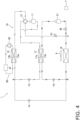
- a two-stage refrigeration cycle is performed in which the second refrigerant is used in the heat-source-side refrigeration cycle and the first refrigerant is used in the use-side refrigeration cycle.
- a single-headed arrow indicates a flow path through which the first refrigerant flows
- a double-headed arrow indicates a flow path through which the second refrigerant flows.
- the use heat exchanger 13 is caused to function as a condenser of the first refrigerant
- the cascade heat exchanger 17 is caused to function as an evaporator of the first refrigerant
- the cascade heat exchanger 17 is caused to function as a radiator of the second refrigerant
- the outdoor heat exchanger 18 is caused to function as an evaporator of the second refrigerant.
- the third expansion valve 14 is controlled to be in a fully closed state, and the first on-off valve 41 is controlled to be in a closed state to prevent mixing of the first refrigerant and the second refrigerant.
- the connection state of the first switching mechanism 12 is switched to a connection state indicated by broken lines in Fig. 4 , the pump 92, the first compressor 11, the second compressor 21, and the outdoor fan 9 are driven, and the second on-off valve 42 is controlled to be in an open state.
- valve opening degree of the first expansion valve 15 is controlled such that the degree of superheating of the first refrigerant to be sucked into the first compressor 11 satisfies a predetermined condition
- valve opening degree of the second expansion valve 16 is controlled such that the degree of superheating of the second refrigerant to be sucked into the second compressor 21 satisfies a predetermined condition.
- the second refrigerant discharged from the second compressor 21 is sent to the cascade heat exchanger 17.
- the second refrigerant radiates heat by heat exchange with the first refrigerant flowing through the first cascade flow path 17a.
- the second refrigerant which has radiated heat in the cascade heat exchanger 17, is decompressed in the second expansion valve 16. After that, the second refrigerant is evaporated by heat exchange with the outdoor air supplied by the outdoor fan 9 in the outdoor heat exchanger 18, and is sucked into the second compressor 21.
- the first refrigerant discharged from the first compressor 11 is sent to the first use flow path 13a of the use heat exchanger 13 via the first switching mechanism 12.
- the first refrigerant flowing through the first use flow path 13a of the use heat exchanger 13 is condensed by heat exchange with the water flowing through the heat-load flow path 13b of the use heat exchanger 13 included in the heat-load circuit 90.
- the water heated by this heat exchange is sent to the heat-load heat exchanger 91 in the heat-load circuit 90 to process the heating load.
- the first refrigerant condensed in the first use flow path 13a of the use heat exchanger 13 passes through the branch point A and is then decompressed in the first expansion valve 15.
- the first refrigerant decompressed by the first expansion valve 15 is evaporated, when passing through the first cascade flow path 17a of the cascade heat exchanger 17, by heat exchange with the second refrigerant flowing through the second cascade flow path 17b.
- the first refrigerant evaporated in the first cascade flow path 17a of the cascade heat exchanger 17 is sucked into the first compressor 11 via the first switching mechanism 12.
- the refrigeration cycle apparatus 1 performs a heating-to-cooling transition operation for making a transition from a cycle state for performing the heating operation to a cycle state for performing the cooling operation.
- the second expansion valve 16 is controlled to be in a fully closed state from the state in which the heating operation is performed, and the second compressor 21 is driven, with the third expansion valve 14 also maintained in the fully closed state.
- the second on-off valve 42 is closed.
- the second refrigerant can be collected in a flow path from the second on-off valve 42 to the second expansion valve 16 via the second compressor 21 and the second cascade flow path 17b of the cascade heat exchanger 17.
- the first expansion valve 15 is controlled to be in a fully closed state, the third expansion valve 14 and the first on-off valve 41 is opened, and the first switching mechanism 12 is brought into a state in which the discharge side of the first compressor 11 is connected to the first on-off valve 41 and the suction side of the first compressor 11 is connected to the gas refrigerant side of the first use flow path 13a of the use heat exchanger 13 and the gas refrigerant side of the first cascade flow path 17a of the cascade heat exchanger 17.
- the refrigerant circuit 10 uses the first refrigerant having a sufficiently low global warming potential (GWP) and the second refrigerant having a sufficiently low ozone depletion potential (ODP) and a sufficiently low global warming potential (GWP).
- GWP global warming potential
- ODP ozone depletion potential
- GWP global warming potential
- the refrigerant circuit 10 uses the first refrigerant having a sufficiently low global warming potential (GWP)
- GWP global warming potential
- the two-stage refrigeration cycle in which the second refrigerant, which is a high-pressure refrigerant, is used in the heat-source-side refrigeration cycle and the first refrigerant, which is a low-pressure refrigerant, is used in the use-side refrigeration cycle is performed as the heating operation.
- the refrigerant circuit 10 uses carbon dioxide as the second refrigerant.
- a single-stage refrigeration cycle using the second refrigerant is not performed, nor is performed a two-stage refrigeration cycle in which the second refrigerant is used in the heat-source-side refrigeration cycle and the first refrigerant is used in the use-side refrigeration cycle. Instead of this, a single-stage refrigeration cycle using the first refrigerant is performed.
- Fig. 5 is a schematic configuration diagram of a refrigeration cycle apparatus 1a according to a second embodiment.
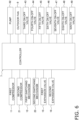
- Fig. 6 is a functional block configuration diagram of the refrigeration cycle apparatus 1a according to the second embodiment.
- the refrigeration cycle apparatus 1a is an apparatus used to process a heat load through a vapor-compression refrigeration cycle operation.
- the refrigeration cycle apparatus 1a includes a heat-load circuit 90, a refrigerant circuit 10, an outdoor fan 9, and a controller 7.
- the heat load to be processed by the refrigeration cycle apparatus 1a and the heat-load circuit 90 are similar to those according to the first embodiment.
- a use heat exchanger 13 includes a first use flow path 13a through which a first refrigerant or a second refrigerant flowing through the refrigerant circuit 10 passes. Water flowing through a heat-load flow path 13b of the use heat exchanger 13 exchanges heat with the first refrigerant or second refrigerant flowing through the first use flow path 13a. As a result, the water is cooled during a cooling operation and is heated during a heating operation.
- the refrigerant circuit 10 includes a first compressor 11, a second compressor 21, a first switching mechanism 12, a second switching mechanism 22, the use heat exchanger 13 shared with the heat-load circuit 90, a first expansion valve 15, a second expansion valve 16, a cascade heat exchanger 17, an outdoor heat exchanger 18, a refrigerant container 19, a third on-off valve 43, a fourth on-off valve 44, a fifth on-off valve 45, a sixth on-off valve 46, a seventh on-off valve 47, an eighth on-off valve 48, and a ninth on-off valve 49.
- the refrigerant circuit 10 is filled with the first refrigerant, which is a low-pressure refrigerant, and the second refrigerant, which is a high-pressure refrigerant, as refrigerants in a substantially separated state.
- the first refrigerant is a refrigerant having 1 MPa or less at 30°C, and is a refrigerant including, for example, at least one of R1234yf or R1234ze.
- the first refrigerant may include only R1234yf or may include only R1234ze.
- the second refrigerant is a refrigerant having 1.5 MPa or more at 30°C.
- the second refrigerant may include carbon dioxide, or may include only carbon dioxide.
- the specific configuration of the first compressor 11 is similar to that according to the first embodiment.
- a discharge side of the first compressor 11 is connected to a first port of a switching valve 12a of the first switching mechanism 12.
- a suction side of the first compressor 11 is connected to a branch point D 1.
- the branch point D1 is connected to a second port of the switching valve 12a of the first switching mechanism 12, a second port of a switching valve 12b of the first switching mechanism 12, and a flow path extending from the eighth on-off valve 48.
- the first switching mechanism 12 includes the switching valve 12a and the switching valve 12b.
- the switching valve 12a is constituted by a four-way switching valve having four ports including the first port, the second port, a third port, and a fourth port.
- the first port of the switching valve 12a is connected to the discharge side of the first compressor 11.
- the second port of the switching valve 12a is connected to the suction side of the first compressor 11.
- the third port of the switching valve 12a is connected to a flow path extending from a branch point E2.
- the fourth port of the switching valve 12a is connected to a first port of the switching valve 12b.
- the switching valve 12b is constituted by a four-way switching valve having four ports including the first port, the second port, a third port, and a fourth port.
- the first port of the switching valve 12b is connected to the fourth port of the switching valve 12a.
- the second port of the switching valve 12b is connected to the suction side of the first compressor 11.
- the third port of the switching valve 12b is connected to a gas refrigerant side of the first use flow path 13a of the use heat exchanger 13.
- the fourth port of the switching valve 12b is connected to a gas refrigerant side of a first cascade flow path 17a of the cascade heat exchanger 17.
- the switching valve 12a switches between a state in which the discharge side of the first compressor 11 is connected to the first port of the switching valve 12b and the suction side of the first compressor 11 is connected to the branch point E2 and a state in which the discharge side of the first compressor 11 is connected to the branch point E2 and the suction side of the first compressor 11 is connected to the first port of the switching valve 12b.
- the switching valve 12b switches between a state in which the fourth port of the switching valve 12a is connected to the gas refrigerant side of the first cascade flow path 17a of the cascade heat exchanger 17 and the suction side of the first compressor 11 is connected to the gas refrigerant side of the first use flow path 13a of the use heat exchanger 13 and a state in which the fourth port of the switching valve 12a is connected to the gas refrigerant side of the first use flow path 13a of the use heat exchanger 13 and the suction side of the first compressor 11 is connected to the gas refrigerant side of the first cascade flow path 17a of the cascade heat exchanger 17.
- the gas refrigerant side of the first use flow path 13a of the use heat exchanger 13 through which the refrigerant flowing through the refrigerant circuit 10 passes is connected to the switching valve 12b of the first switching mechanism 12.
- Aliquid refrigerant side of the first use flow path 13a is connected to a branch point A included in the refrigerant circuit 10.
- a flow path extending from the liquid refrigerant side of the first use flow path 13a, a flow path extending to the side of the first expansion valve 15 opposite to the cascade heat exchanger 17 side, and a flow path extending from a branch point J are connected.
- the first expansion valve 15 is configured as an electronic expansion valve that is adjustable in valve opening degree. In the refrigerant circuit 10, the first expansion valve 15 is disposed at a certain point in a flow path connecting the branch point A and a branch point F.
- the branch point F connects a flow path extending from the first expansion valve 15, a flow path extending from a branch point H1, and a flow path extending from a liquid refrigerant side of the first cascade flow path 17a of the cascade heat exchanger 17.
- the cascade heat exchanger 17 is a cascade heat exchanger that includes the first cascade flow path 17a through which one of the first refrigerant and the second refrigerant passes and a second cascade flow path 17b through which the other of the first refrigerant and the second refrigerant passes, and that exchanges heat between the first refrigerant and the second refrigerant.
- the first cascade flow path 17a and the second cascade flow path 17b are independent of each other, and the first refrigerant and the second refrigerant do not mix with each other in the cascade heat exchanger 17.
- the gas refrigerant side of the first cascade flow path 17a is connected to the switching valve 12b of the first switching mechanism 12.
- the liquid refrigerant side of the first cascade flow path 17a is connected to a flow path extending from the branch point F.
- a gas refrigerant side of the second cascade flow path 17b is connected to a switching valve 22b of the second switching mechanism 22.
- a liquid refrigerant side of the second cascade flow path 17b is connected to a flow path extending from a branch point G.
- the specific configuration of the second compressor 21 is similar to that according to the first embodiment.
- a discharge side of the second compressor 21 is connected to a first port of a switching valve 22a of the second switching mechanism 22.
- a suction side of the second compressor 21 is connected to a branch point E1.
- the branch point E1 is connected to a second port of the switching valve 22a of the second switching mechanism 22, a second port of the switching valve 22b of the second switching mechanism 22, and a flow path extending from the seventh on-off valve 47.
- the second switching mechanism 22 includes the switching valve 22a and the switching valve 22b.
- the switching valve 22a is constituted by a four-way switching valve having four ports including the first port, the second port, a third port, and a fourth port.
- the first port of the switching valve 22a is connected to the discharge side of the second compressor 21.
- the second port of the switching valve 22a is connected to the suction side of the second compressor 21.
- the third port of the switching valve 22a is connected to a flow path extending from a branch point D2.
- the fourth port of the switching valve 22a is connected to a first port of the switching valve 22b.
- the switching valve 22b is constituted by a four-way switching valve having four ports including the first port, the second port, a third port, and a fourth port.
- the first port of the switching valve 22b is connected to the fourth port of the switching valve 22a.
- the second port of the switching valve 22b is connected to the suction side of the second compressor 21.
- the third port of the switching valve 22b is connected to the gas refrigerant side of the second cascade flow path 17b of the cascade heat exchanger 17.
- the fourth port of the switching valve 22b is connected to a gas refrigerant side of the outdoor heat exchanger 18.
- the switching valve 22a switches between a state in which the discharge side of the second compressor 21 is connected to the first port of the switching valve 22b and the suction side of the second compressor 21 is connected to the branch point D2 and a state in which the discharge side of the second compressor 21 is connected to the branch point D2 and the suction side of the second compressor 21 is connected to the first port of the switching valve 22b.
- the switching valve 22b switches between a state in which the fourth port of the switching valve 22a is connected to the gas refrigerant side of the outdoor heat exchanger 18 and the suction side of the second compressor 21 is connected to the gas refrigerant side of the second cascade flow path 17b of the cascade heat exchanger 17 and a state in which the fourth port of the switching valve 22a is connected to the gas refrigerant side of the second cascade flow path 17b of the cascade heat exchanger 17 and the suction side of the second compressor 21 is connected to the gas refrigerant side of the outdoor heat exchanger 18.
- the branch point G is connected to a flow path extending from the liquid refrigerant side of the second cascade flow path 17b of the cascade heat exchanger 17, a flow path extending from the second expansion valve 16, and a flow path extending from a branch point H2.
- the second expansion valve 16 is configured as an electronic expansion valve that is adjustable in valve opening degree.
- the second expansion valve 16 is disposed between the branch point G and the liquid refrigerant side of the outdoor heat exchanger 18.
- the outdoor heat exchanger 18 includes a plurality of heat transfer tubes and a plurality of fins joined to the plurality of heat transfer tubes.
- the outdoor heat exchanger 18 is arranged outdoors. A refrigerant flowing through the outdoor heat exchanger 18 exchanges heat with air sent to the outdoor heat exchanger 18.
- the outdoor fan 9 generates an air flow of outdoor air passing through the outdoor heat exchanger 18.
- the branch point J is connected to a flow path extending from the branch point A, a flow path extending from the sixth on-off valve 46, and a flow path extending from a branch point K 1.
- the branch point K1 connects a flow path extending from the branch point J, a flow path extending from an upper end portion of the refrigerant container 19, and a flow path extending from the ninth on-off valve 49.
- the ninth on-off valve 49 is disposed at a certain point in a flow path connecting the branch point D2 and the branch point K1.
- the branch point D2 connects a flow path extending from the ninth on-off valve 49, a flow path extending from the eighth on-off valve 48, and a flow path extending from the third port of the switching valve 22a of the second switching mechanism 22.
- the eighth on-off valve 48 is disposed at a certain point in a flow path connecting the branch point D2 and the branch point D1.
- the sixth on-off valve 46 is disposed at a certain point in a flow path connecting the branch point J and the branch point E2.
- the branch point E2 connects a flow path extending from the seventh on-off valve 47, a flow path extending from the sixth on-off valve 46, and a flow path extending from the third port of the switching valve 12a of the first switching mechanism 12.
- the seventh on-off valve 47 is disposed at a certain point in a flow path connecting the branch point E1 and the branch point E2.
- a branch point K2 connects a flow path extending from a lower end portion of the refrigerant container 19, a flow path extending from the fourth on-off valve 44, and a flow path extending from the fifth on-off valve 45.
- the fourth on-off valve 44 is disposed at a certain point in a flow path connecting the branch point K2 and the branch point H1.
- the fifth on-off valve 45 is disposed at a certain point in a flow path connecting the branch point K2 and the branch point H2.
- the branch point H1 connects a flow path extending from the third on-off valve 43, a flow path extending from the fourth on-off valve 44, and a flow path extending from the branch point F.
- the branch point H2 connects a flow path extending from the third on-off valve 43, a flow path extending from the fifth on-off valve 45, and a flow path extending from the branch point G.
- the third on-off valve 43 is disposed at a certain point in a flow path connecting the branch point H1 and the branch point H2.
- the third on-off valve 43, the fourth on-off valve 44, the fifth on-off valve 45, the sixth on-off valve 46, the seventh on-off valve 47, the eighth on-off valve 48, and the ninth on-off valve 49 are each an electromagnetic valve controllable to switch between an open state and a closed state.
- the refrigerant container 19 is a container capable of holding therein the first refrigerant or the second refrigerant.
- the refrigerant container 19 can be used to move the second refrigerant within the refrigerant circuit 10 while the first refrigerant is stored in the refrigerant container 19 or to move the first refrigerant within the refrigerant circuit 10 while the second refrigerant is stored in the refrigerant container 19.
- the refrigerant container 19 has a capacity such that the refrigerant container 19 can store the first refrigerant and store the second refrigerant.
- the refrigerant container 19 used to move the first refrigerant within the refrigerant circuit 10 while the second refrigerant is stored in the refrigerant container 19 will be described as an example.
- the controller 7 controls the operation of the devices included in the heat-load circuit 90 and the refrigerant circuit 10.
- the controller 7 includes a processor serving as a CPU provided for performing control, a memory, and the like.
- the controller 7 controls the devices to execute a refrigeration cycle, thereby performing a cooling operation for processing a cooling load in the heat-load heat exchanger 91, a heating operation for processing a heating load in the heat-load heat exchanger 91, a cooling-to-heating transition operation, and a heating-to-cooling transition operation.
- a two-stage refrigeration cycle operation is performed in which the first refrigerant is used in a heat-source-side refrigeration cycle and the second refrigerant is used in a use-side refrigeration cycle.
- a single-headed arrow indicates a flow path through which the first refrigerant flows
- a double-headed arrow indicates a flow path through which the second refrigerant flows.
- the use heat exchanger 13 is caused to function as an evaporator of the second refrigerant
- the cascade heat exchanger 17 is caused to function as a radiator of the second refrigerant
- the cascade heat exchanger 17 is caused to function as an evaporator of the first refrigerant
- the outdoor heat exchanger 18 is caused to function as a condenser of the first refrigerant.
- valve opening degree of the first expansion valve 15 is controlled such that the degree of superheating of the second refrigerant to be sucked into the first compressor 11 satisfies a predetermined condition
- valve opening degree of the second expansion valve 16 is controlled such that the degree of superheating of the first refrigerant to be sucked into the second compressor 21 satisfies a predetermined condition.
- the first refrigerant discharged from the second compressor 21 is sent to the outdoor heat exchanger 18 via the switching valve 22a and the switching valve 22b of the second switching mechanism 22.
- the first refrigerant flowing through the outdoor heat exchanger 18 is condensed by heat exchange with the outdoor air supplied by the outdoor fan 9.
- the first refrigerant condensed in the outdoor heat exchanger 18 is decompressed in the second expansion valve 16, passes through the branch point G, and is sent to the second cascade flow path 17b of the cascade heat exchanger 17.
- the first refrigerant is evaporated by heat exchange with the second refrigerant flowing through the first cascade flow path 17a.
- the first refrigerant evaporated in the cascade heat exchanger 17 is sucked into the second compressor 21 via the switching valve 22b of the second switching mechanism 22.
- the second refrigerant discharged from the first compressor 11 is sent to the first cascade flow path 17a of the cascade heat exchanger 17 via the switching valve 12a and the switching valve 12b of the first switching mechanism 12.
- the second refrigerant radiates heat by heat exchange with the first refrigerant flowing through the second cascade flow path 17b.
- the second refrigerant which has radiated heat in the cascade heat exchanger 17, passes through the branch point F, is decompressed in the first expansion valve 15, passes through the branch point A, and is sent to the first use flow path 13a of the use heat exchanger 13.
- the second refrigerant flowing through the first use flow path 13a of the use heat exchanger 13 is evaporated by heat exchange with the water flowing through the heat-load flow path 13b of the use heat exchanger 13 included in the heat-load circuit 90.
- the water cooled by this heat exchange is sent to the heat-load heat exchanger 91 in the heat-load circuit 90 to process the cooling load.
- the second refrigerant evaporated in the first use flow path 13a of the use heat exchanger 13 is sucked into the first compressor 11 via the switching valve 12b of the first switching mechanism 12.
- the refrigeration cycle apparatus 1a performs a cooling-to-heating transition operation including (a1) to (f1) below in this order to make a transition from a cycle state for performing the cooling operation to a cycle state for performing the heating operation.
- a two-stage refrigeration cycle is performed in which the second refrigerant is used in the heat-source-side refrigeration cycle and the first refrigerant is used in the use-side refrigeration cycle.
- a single-headed arrow indicates a flow path through which the first refrigerant flows
- a double-headed arrow indicates a flow path through which the second refrigerant flows.
- the use heat exchanger 13 is caused to function as a condenser of the first refrigerant
- the cascade heat exchanger 17 is caused to function as an evaporator of the first refrigerant
- the cascade heat exchanger 17 is caused to function as a radiator of the second refrigerant
- the outdoor heat exchanger 18 is caused to function as an evaporator of the second refrigerant.
- a connection state of the switching valve 22a of the second switching mechanism 22 is changed to a state indicated by solid lines in Fig. 8
- a connection state of the switching valve 22b of the second switching mechanism 22 is switched to a connection state indicated by broken lines in Fig. 8
- the pump 92, the first compressor 11, the second compressor 21, and the outdoor fan 9 are driven.
- the valve opening degree of the first expansion valve 15 is controlled such that the degree of superheating of the first refrigerant to be sucked into the first compressor 11 satisfies a predetermined condition
- the valve opening degree of the second expansion valve 16 is controlled such that the degree of superheating of the second refrigerant to be sucked into the second compressor 21 satisfies a predetermined condition.
- the second refrigerant discharged from the second compressor 21 is sent to the cascade heat exchanger 17.
- the second refrigerant radiates heat by heat exchange with the first refrigerant flowing through the first cascade flow path 17a.
- the second refrigerant which has radiated heat in the cascade heat exchanger 17, is decompressed in the second expansion valve 16. After that, the second refrigerant is evaporated by heat exchange with the outdoor air supplied by the outdoor fan 9 in the outdoor heat exchanger 18, and is sucked into the second compressor 21.
- the first refrigerant discharged from the first compressor 11 is sent to the first use flow path 13a of the use heat exchanger 13 via the first switching mechanism 12.
- the first refrigerant flowing through the first use flow path 13a of the use heat exchanger 13 is condensed by heat exchange with the water flowing through the heat-load flow path 13b of the use heat exchanger 13 included in the heat-load circuit 90.
- the water heated by this heat exchange is sent to the heat-load heat exchanger 91 in the heat-load circuit 90 to process the heating load.
- the first refrigerant condensed in the first use flow path 13a of the use heat exchanger 13 passes through the branch point A and is then decompressed in the first expansion valve 15.
- the first refrigerant decompressed by the first expansion valve 15 is evaporated, when passing through the first cascade flow path 17a of the cascade heat exchanger 17, by heat exchange with the second refrigerant flowing through the second cascade flow path 17b.
- the first refrigerant evaporated in the first cascade flow path 17a of the cascade heat exchanger 17 is sucked into the first compressor 11 via the first switching mechanism 12.
- the refrigeration cycle apparatus 1a performs a heating-to-cooling transition operation including (a2) to (f2) below in this order to make a transition from a cycle state for performing the heating operation to a cycle state for performing the cooling operation.
- the refrigerant circuit 10 uses the first refrigerant having a sufficiently low global warming potential (GWP) and the second refrigerant having a sufficiently low ozone depletion potential (ODP) and a sufficiently low global warming potential (GWP).
- GWP global warming potential
- ODP ozone depletion potential
- GWP global warming potential
- the refrigerant circuit 10 uses the first refrigerant having a sufficiently low global warming potential (GWP)
- GWP global warming potential
- the two-stage refrigeration cycle in which the second refrigerant, which is a high-pressure refrigerant, is used in the heat-source-side refrigeration cycle and the first refrigerant, which is a low-pressure refrigerant, is used in the use-side refrigeration cycle is performed as the heating operation.
- the refrigerant circuit 10 uses carbon dioxide as the second refrigerant.
- a single-stage refrigeration cycle using the second refrigerant is not performed, nor is performed a two-stage refrigeration cycle in which the second refrigerant is used in the heat-source-side refrigeration cycle and the first refrigerant is used in the use-side refrigeration cycle.
- a two-stage refrigeration cycle in which the first refrigerant, which is a low-pressure refrigerant, is used in the heat-source-side refrigeration cycle and the second refrigerant, which is a high-pressure refrigerant, is used in the use-side refrigeration cycle is performed.
- Fig. 9 is a schematic configuration diagram of a refrigeration cycle apparatus 1b according to a third embodiment.
- Fig. 10 is a functional block configuration diagram of the refrigeration cycle apparatus 1b according to the third embodiment.
- the refrigeration cycle apparatus 1b is an apparatus used to process a heat load through a vapor-compression refrigeration cycle operation.
- the refrigeration cycle apparatus 1b includes a heat-load circuit 90, a refrigerant circuit 10, an outdoor fan 9, and a controller 7.
- the heat load to be processed by the refrigeration cycle apparatus 1b and the heat-load circuit 90 are similar to those according to the first embodiment.
- a use heat exchanger 13 includes a first use flow path 13a through which a first refrigerant or a second refrigerant flowing through the refrigerant circuit 10 passes. Water flowing through a heat-load flow path 13b of the use heat exchanger 13 exchanges heat with the first refrigerant or second refrigerant flowing through the first use flow path 13a. As a result, the water is cooled during a cooling operation and is heated during a heating operation.
- the refrigerant circuit 10 includes a first compressor 11, a second compressor 21, a first switching mechanism 12, a second switching mechanism 22, the use heat exchanger 13 shared with the heat-load circuit 90, a first expansion valve 15, a second expansion valve 16, a third expansion valve 33, a fourth expansion valve 34, a fifth expansion valve 35, a sixth expansion valve 36, a cascade heat exchanger 17, an outdoor heat exchanger 18, a first receiver 19a, a second receiver 19b, a tenth on-off valve 50, an eleventh on-off valve 51, a twelfth on-off valve 52, and a thirteenth on-off valve 53.
- the refrigerant circuit 10 is filled with the first refrigerant, which is a low-pressure refrigerant, and the second refrigerant, which is a high-pressure refrigerant, as refrigerants in a substantially separated state.
- the first refrigerant is a refrigerant having 1 MPa or less at 30°C, and is a refrigerant including, for example, at least one of R1234yf or R1234ze.
- the first refrigerant may include only R1234yf or may include only R1234ze.
- the second refrigerant is a refrigerant having 1.5 MPa or more at 30°C.
- the second refrigerant may include carbon dioxide, or may include only carbon dioxide.
- the specific configuration of the first compressor 11 is similar to that according to the first embodiment.
- a discharge side of the first compressor 11 is connected to a first port of the first switching mechanism 12.
- a suction side of the first compressor 11 is connected to a second port of the first switching mechanism 12.
- the first switching mechanism 12 is constituted by a four-way switching valve having four ports including the first port, the second port, a third port, and a fourth port.
- the first port of the first switching mechanism 12 is connected to a branch point P.
- the branch point P is connected to a flow path extending from the discharge side of the first compressor 11, a flow path extending from a gas refrigerant side of a first cascade flow path 17a of the cascade heat exchanger 17, and a flow path extending from the first port of the first switching mechanism 12.
- the second port of the first switching mechanism 12 is connected to the suction side of the first compressor 11.
- the third port of the first switching mechanism 12 is connected to a flow path extending from the eleventh on-off valve 51.
- the fourth port of the first switching mechanism 12 is connected to a flow path extending from the tenth on-off valve 50.
- the first switching mechanism 12 switches between a state in which the branch point P is connected to the eleventh on-off valve 51 and the suction side of the first compressor 11 is connected to the tenth on-off valve 50 and a state in which the branch point P is connected to the tenth on-off valve 50 and the suction side of the first compressor 11 is connected to the eleventh on-off valve 51.
- the tenth on-off valve 50 is an electromagnetic valve controllable to switch between an open state and a closed state.
- the tenth on-off valve 50 is disposed at a certain point in a flow path connecting the fourth port of the first switching mechanism 12 and a branch point M.
- the branch point M is connected to a flow path extending from the tenth on-off valve 50, a flow path extending from the thirteenth on-off valve 53, and a flow path extending from a gas refrigerant side of the first use flow path 13a of the use heat exchanger 13.
- the gas refrigerant side of the first use flow path 13a of the use heat exchanger 13 through which the refrigerant flowing through the refrigerant circuit 10 passes is connected to a flow path extending from the branch point M.
- a liquid refrigerant side of the first use flow path 13a is connected to a flow path extending from a branch point A.
- a flow path extending from the liquid refrigerant side of the first use flow path 13a, a flow path extending to the side of the first expansion valve 15 opposite to a branch point F side, and a flow path extending from the sixth expansion valve 36 are connected.
- the first expansion valve 15 is configured as an electronic expansion valve that is adjustable in valve opening degree. In the refrigerant circuit 10, the first expansion valve 15 is disposed at a certain point in a flow path connecting the branch point A and the branch point F.
- the branch point F connects a flow path extending from the first expansion valve 15, a flow path extending from the fifth expansion valve 35, and a flow path extending from an upper end of the first receiver 19a.
- the first receiver 19a is a refrigerant container that stores a refrigerant therein.
- the first receiver 19a is disposed at a certain point in a flow path connecting the branch point F and the third expansion valve 33.
- the first receiver 19a stores the second refrigerant.
- the third expansion valve 33 is configured as an electronic expansion valve that is adjustable in valve opening degree.
- the third expansion valve 33 is disposed at a certain point in a flow path connecting a lower end of the first receiver 19a and a liquid refrigerant side of the first cascade flow path 17a of the cascade heat exchanger 17.
- the cascade heat exchanger 17 is a cascade heat exchanger that includes the first cascade flow path 17a through which one of the first refrigerant and the second refrigerant passes and a second cascade flow path 17b through which the other of the first refrigerant and the second refrigerant passes, and that exchanges heat between the first refrigerant and the second refrigerant.
- the first cascade flow path 17a and the second cascade flow path 17b are independent of each other, and the first refrigerant and the second refrigerant do not mix with each other in the cascade heat exchanger 17.
- the gas refrigerant side of the first cascade flow path 17a is connected to a flow path extending from the branch point P.
- the liquid refrigerant side of the first cascade flow path 17a is connected to a flow path extending from the third expansion valve 33.
- a gas refrigerant side of the second cascade flow path 17b is connected to a flow path extending from a second port of the second switching mechanism 22 and a flow path extending from a suction side of the second compressor 21.
- a liquid refrigerant side of the second cascade flow path 17b is connected to a flow path extending from the fourth expansion valve 34.
- the specific configuration of the second compressor 21 is similar to that according to the first embodiment.
- a discharge side of the second compressor 21 is connected to a first port of the second switching mechanism 22.
- the suction side of the second compressor 21 is connected to the second port of the second switching mechanism 22 and the gas refrigerant side of the second cascade flow path 17b of the cascade heat exchanger 17.
- the second switching mechanism 22 is constituted by a four-way switching valve having four ports including the first port, the second port, a third port, and a fourth port.
- the first port of the second switching mechanism 22 is connected to the discharge side of the second compressor 21.
- the second port of the second switching mechanism 22 is connected to the suction side of the second compressor 21 and the gas refrigerant side of the second cascade flow path 17b of the cascade heat exchanger 17.
- the third port of the second switching mechanism 22 is connected to a flow path extending from the thirteenth on-off valve 53.
- the fourth port of the second switching mechanism 22 is connected to a flow path extending from the twelfth on-off valve 52.
- the second switching mechanism 22 switches between a state in which the discharge side of the second compressor 21 is connected to the twelfth on-off valve 52 and the suction side of the second compressor 21 and the gas refrigerant side of the second cascade flow path 17b of the cascade heat exchanger 17 are connected to the thirteenth on-off valve 53 and a state in which the discharge side of the second compressor 21 is connected to the thirteenth on-off valve 53 and the suction side of the second compressor 21 and the gas refrigerant side of the second cascade flow path 17b of the cascade heat exchanger 17 are connected to the twelfth on-off valve 52.
- the liquid refrigerant side of the second cascade flow path 17b of the cascade heat exchanger 17 is connected to a flow path extending from the fourth expansion valve 34.
- the fourth expansion valve 34 is configured as an electronic expansion valve that is adjustable in valve opening degree.
- the fourth expansion valve 34 is disposed between the liquid refrigerant side of the second cascade flow path 17b of the cascade heat exchanger 17 and an upper end of the second receiver 19b.
- the second receiver 19b is a refrigerant container that stores a refrigerant therein.
- the second receiver 19b is disposed at a certain point in a flow path connecting a branch point G and the fourth expansion valve 34.
- the second receiver 19b stores the first refrigerant.
- the branch point G is connected to a flow path extending from a lower end of the second receiver 19b, a flow path extending from the sixth expansion valve 36, and a flow path extending from the second expansion valve 16.
- the second expansion valve 16 is configured as an electronic expansion valve that is adjustable in valve opening degree.
- the second expansion valve 16 is disposed between the branch point G and a branch point B.
- the branch point B is connected to a flow path extending from the second expansion valve 16, a flow path extending from a liquid refrigerant side of the outdoor heat exchanger 18, and a flow path extending from the fifth expansion valve 35.
- the outdoor heat exchanger 18 includes a plurality of heat transfer tubes and a plurality of fins joined to the plurality of heat transfer tubes.
- the outdoor heat exchanger 18 is arranged outdoors. A refrigerant flowing through the outdoor heat exchanger 18 exchanges heat with air sent to the outdoor heat exchanger 18.
- the outdoor heat exchanger 18 is disposed at a certain point in a flow path connecting the branch point B and a branch point N.
- the outdoor fan 9 generates an air flow of outdoor air passing through the outdoor heat exchanger 18.
- the branch point N is connected to a flow path extending from a gas refrigerant side of the outdoor heat exchanger 18, a flow path extending from the twelfth on-off valve 52, and a flow path extending from the eleventh on-off valve 51.
- the eleventh on-off valve 51 is an electromagnetic valve controllable to switch between an open state and a closed state.
- the eleventh on-off valve 51 is disposed at a certain point in a flow path connecting the third port of the first switching mechanism 12 and the branch point N.
- the twelfth on-off valve 52 is an electromagnetic valve controllable to switch between an open state and a closed state.
- the twelfth on-off valve 52 is disposed at a certain point in a flow path connecting the fourth port of the second switching mechanism 22 and the branch point N.
- the thirteenth on-off valve 53 is an electromagnetic valve controllable to switch between an open state and a closed state.
- the thirteenth on-off valve 53 is disposed at a certain point in a flow path connecting the third port of the second switching mechanism 22 and the branch point M.
- the fifth expansion valve 35 is configured as an electronic expansion valve that is adjustable in valve opening degree.
- the fifth expansion valve 35 is disposed at a certain point in a flow path connecting the branch point F and the branch point B.
- the sixth expansion valve 36 is configured as an electronic expansion valve that is adjustable in valve opening degree.
- the sixth expansion valve 36 is disposed at a certain point in a flow path connecting the branch point A and the branch point G.
- the controller 7 controls the operation of the devices included in the heat-load circuit 90 and the refrigerant circuit 10.
- the controller 7 includes a processor serving as a CPU provided for performing control, a memory, and the like.
- the controller 7 controls the devices to execute a refrigeration cycle, thereby performing a cooling operation for processing a cooling load in the heat-load heat exchanger 91, a heating operation for processing a heating load in the heat-load heat exchanger 91, a cooling-to-heating transition operation, and a heating-to-cooling transition operation.
- a two-stage refrigeration cycle operation is performed in which the first refrigerant is used in a heat-source-side refrigeration cycle and the second refrigerant is used in a use-side refrigeration cycle.
- a single-headed arrow indicates a flow path through which the first refrigerant flows
- a double-headed arrow indicates a flow path through which the second refrigerant flows.
- the use heat exchanger 13 is caused to function as an evaporator of the second refrigerant
- the cascade heat exchanger 17 is caused to function as a radiator of the second refrigerant
- the cascade heat exchanger 17 is caused to function as an evaporator of the first refrigerant
- the outdoor heat exchanger 18 is caused to function as a condenser of the first refrigerant.
- all of the eleventh on-off valve 51 and the thirteenth on-off valve 53 are controlled to be in a closed state, and the fifth expansion valve 35 and the sixth expansion valve 36 are controlled to be in a fully closed state to prevent mixing of the first refrigerant and the second refrigerant.
- the tenth on-off valve 50 and the twelfth on-off valve 52 are controlled to be in an open state. Then, a connection state of the first switching mechanism 12 is switched to a connection state indicated by solid lines in Fig. 11 , a connection state of the second switching mechanism 22 is switched to a connection state indicated by solid lines in Fig. 11 , and the pump 92, the first compressor 11, the second compressor 21, and the outdoor fan 9 are driven.
- valve opening degree of the first expansion valve 15 is controlled such that the degree of superheating of the second refrigerant to be sucked into the first compressor 11 satisfies a predetermined condition
- valve opening degree of the fourth expansion valve 34 is controlled such that the degree of superheating of the first refrigerant to be sucked into the second compressor 21 satisfies a predetermined condition.
- the first refrigerant discharged from the second compressor 21 is sent to the outdoor heat exchanger 18 via the second switching mechanism 22 and the twelfth on-off valve 52.
- the first refrigerant flowing through the outdoor heat exchanger 18 is condensed by heat exchange with the outdoor air supplied by the outdoor fan 9.
- the first refrigerant condensed in the outdoor heat exchanger 18 passes through the second expansion valve 16, which is controlled to be in a fully open state. After that, the first refrigerant passes through the branch point G and flows into the second receiver 19b.
- the refrigerant having flowed out of the second receiver 19b is decompressed in the fourth expansion valve 34 and is sent to the second cascade flow path 17b of the cascade heat exchanger 17.
- the first refrigerant When flowing through the second cascade flow path 17b of the cascade heat exchanger 17, the first refrigerant is evaporated by heat exchange with the second refrigerant flowing through the first cascade flow path 17a.
- the first refrigerant evaporated in the cascade heat exchanger 17 is sucked into the second compressor 21.
- the second refrigerant discharged from the first compressor 11 passes through the branch point P and is sent to the first cascade flow path 17a of the cascade heat exchanger 17.
- the second refrigerant When flowing through the first cascade flow path 17a of the cascade heat exchanger 17, the second refrigerant radiates heat by heat exchange with the first refrigerant flowing through the second cascade flow path 17b.
- the second refrigerant which has radiated heat in the cascade heat exchanger 17, passes through the third expansion valve 33, which is controlled to be in a fully open state, and flows into the first receiver 19a.
- the second refrigerant having flowed out of the first receiver 19a is decompressed in the first expansion valve 15, passes through the branch point A, and is sent to the first use flow path 13a of the use heat exchanger 13.
- the second refrigerant flowing through the first use flow path 13a of the use heat exchanger 13 is evaporated by heat exchange with the water flowing through the heat-load flow path 13b of the use heat exchanger 13 included in the heat-load circuit 90.
- the water cooled by this heat exchange is sent to the heat-load heat exchanger 91 in the heat-load circuit 90 to process the cooling load.
- the second refrigerant evaporated in the first use flow path 13a of the use heat exchanger 13 is sucked into the first compressor 11 via the tenth on-off valve 50 and the first switching mechanism 12.
- the refrigeration cycle apparatus 1b performs a cooling-to-heating transition operation including (a3) to (b3) below in this order to make a transition from a cycle state for performing the cooling operation to a cycle state for performing the heating operation.
- a two-stage refrigeration cycle is performed in which the second refrigerant is used in the heat-source-side refrigeration cycle and the first refrigerant is used in the use-side refrigeration cycle.
- a single-headed arrow indicates a flow path through which the first refrigerant flows
- a double-headed arrow indicates a flow path through which the second refrigerant flows.
- the use heat exchanger 13 is caused to function as a condenser of the first refrigerant
- the cascade heat exchanger 17 is caused to function as an evaporator of the first refrigerant
- the cascade heat exchanger 17 is caused to function as a radiator of the second refrigerant
- the outdoor heat exchanger 18 is caused to function as an evaporator of the second refrigerant.
- the tenth on-off valve 50 and the twelfth on-off valve 52 are controlled to be in a closed state, and the first expansion valve 15 and the second expansion valve 16 are controlled to be in a fully closed state to prevent mixing of the first refrigerant and the second refrigerant.
- a connection state of the first switching mechanism 12 is changed to a state indicated by broken lines in Fig. 12
- a connection state of the second switching mechanism 22 is switched to a connection state indicated by broken lines in Fig. 12
- the pump 92, the first compressor 11, the second compressor 21, and the outdoor fan 9 are driven.
- valve opening degree of the fifth expansion valve 35 is controlled such that the degree of superheating of the second refrigerant to be sucked into the first compressor 11 satisfies a predetermined condition
- valve opening degree of the fourth expansion valve 34 is controlled such that the degree of superheating of the first refrigerant to be sucked into the second compressor 21 satisfies a predetermined condition.
- the second refrigerant discharged from the first compressor 11 is sent to the cascade heat exchanger 17.
- the second refrigerant radiates heat by heat exchange with the first refrigerant flowing through the second cascade flow path 17b.
- the second refrigerant, which has radiated heat in the cascade heat exchanger 17, is decompressed in the fifth expansion valve 35 via the third expansion valve 33, the first receiver 19a, and the branch point F.
- the second refrigerant decompressed in the fifth expansion valve 35 is sent to the outdoor heat exchanger 18 via the branch point B.
- the second refrigerant is evaporated by heat exchange with the outdoor air supplied by the outdoor fan 9 in the outdoor heat exchanger 18, and is sucked into the first compressor 11 via the branch point N, the eleventh on-off valve 51, and the first switching mechanism 12.
- the first refrigerant discharged from the second compressor 21 is sent to the first use flow path 13a of the use heat exchanger 13 via the second switching mechanism 22, the thirteenth on-off valve 53, and the branch point M.
- the first refrigerant flowing through the first use flow path 13a of the use heat exchanger 13 is condensed by heat exchange with the water flowing through the heat-load flow path 13b of the use heat exchanger 13 included in the heat-load circuit 90.
- the water heated by this heat exchange is sent to the heat-load heat exchanger 91 in the heat-load circuit 90 to process the heating load.
- the first refrigerant condensed in the first use flow path 13a of the use heat exchanger 13 passes through the branch point A. After that, the first refrigerant passes through the sixth expansion valve 36 and flows into the second receiver 19b.
- the first refrigerant having flowed out of the second receiver 19b is decompressed in the fourth expansion valve 34.
- the first refrigerant decompressed by the fourth expansion valve 34 is evaporated, when passing through the second cascade flow path 17b of the cascade heat exchanger 17, by heat exchange with the second refrigerant flowing through the first cascade flow path 17a.
- the first refrigerant evaporated in the second cascade flow path 17b of the cascade heat exchanger 17 is sucked into the second compressor 21.
- the refrigeration cycle apparatus 1b performs a heating-to-cooling transition operation including (a4) to (c4) below in this order to make a transition from a cycle state for performing the heating operation to a cycle state for performing the cooling operation.
- the refrigerant circuit 10 uses the first refrigerant having a sufficiently low global warming potential (GWP) and the second refrigerant having a sufficiently low ozone depletion potential (ODP) and a sufficiently low global warming potential (GWP).
- GWP global warming potential
- ODP ozone depletion potential
- GWP global warming potential
- the refrigerant circuit 10 uses the first refrigerant having a sufficiently low global warming potential (GWP)
- GWP global warming potential
- the two-stage refrigeration cycle in which the second refrigerant, which is a high-pressure refrigerant, is used in the heat-source-side refrigeration cycle and the first refrigerant, which is a low-pressure refrigerant, is used in the use-side refrigeration cycle is performed as the heating operation.
- the refrigerant circuit 10 uses carbon dioxide as the second refrigerant.
- a single-stage refrigeration cycle using the second refrigerant is not performed, nor is performed a two-stage refrigeration cycle in which the second refrigerant is used in the heat-source-side refrigeration cycle and the first refrigerant is used in the use-side refrigeration cycle.
- a two-stage refrigeration cycle in which the first refrigerant, which is a low-pressure refrigerant, is used in the heat-source-side refrigeration cycle and the second refrigerant, which is a high-pressure refrigerant, is used in the use-side refrigeration cycle is performed.
- the first refrigerant and the second refrigerant can be collected by using the first receiver 19a and the second receiver 19b used in the heat-source-side refrigeration cycle and the use-side refrigeration cycle. This eliminates the need to separately secure the refrigerant container 19 as described in the second embodiment, which is not used in the heat-source-side refrigeration cycle or the use-side refrigeration cycle.
- Fig. 13 is a schematic configuration diagram of a refrigeration cycle apparatus 1c according to a fourth embodiment.
- Fig. 14 is a functional block configuration diagram of the refrigeration cycle apparatus 1c according to the fourth embodiment.
- the refrigeration cycle apparatus 1c is an apparatus used to process a heat load through a vapor-compression refrigeration cycle operation.
- the refrigeration cycle apparatus 1c includes a heat-load circuit 90, a refrigerant circuit 10, an outdoor fan 9, and a controller 7.
- the heat load to be processed by the refrigeration cycle apparatus 1c and the heat-load circuit 90 are similar to those according to the first embodiment.
- a use heat exchanger 13 includes a first use flow path 13a through which a first refrigerant or a second refrigerant flowing through the refrigerant circuit 10 passes. Water flowing through a heat-load flow path 13b of the use heat exchanger 13 exchanges heat with the first refrigerant or second refrigerant flowing through the first use flow path 13a. As a result, the water is cooled during a cooling operation and is heated during a heating operation.
- the refrigerant circuit 10 includes a first compressor 11, a second compressor 21, a first switching mechanism 12, a second switching mechanism 22, the use heat exchanger 13 shared with the heat-load circuit 90, a first expansion valve 15, a second expansion valve 16, a third expansion valve 33, a fourth expansion valve 34, a fifth expansion valve 35, a sixth expansion valve 36, a cascade heat exchanger 17, an outdoor heat exchanger 18, a first receiver 19a, a second receiver 19b, a fourteenth on-off valve 54, a fifteenth on-off valve 55, a sixteenth on-off valve 56, and a seventeenth on-off valve 57.
- the refrigerant circuit 10 is filled with the first refrigerant, which is a low-pressure refrigerant, and the second refrigerant, which is a high-pressure refrigerant, as refrigerants in a substantially separated state.
- the first refrigerant is a refrigerant having 1 MPa or less at 30°C, and is a refrigerant including, for example, at least one of R1234yf or R1234ze.
- the first refrigerant may include only R1234yf or may include only R1234ze.
- the second refrigerant is a refrigerant having 1.5 MPa or more at 30°C.
- the second refrigerant may include carbon dioxide, or may include only carbon dioxide.
- the specific configuration of the first compressor 11 is similar to that according to the first embodiment.
- a discharge side of the first compressor 11 is connected to a switching valve 12c, a switching valve 12d, and a switching valve 12e of the first switching mechanism 12.
- a suction side of the first compressor 11 is connected to different ports of the switching valve 12c, the switching valve 12d, and the switching valve 12e of the first switching mechanism 12.
- the first switching mechanism 12 includes the switching valve 12c, the switching valve 12d, and the switching valve 12e, which are disposed in parallel to each other on the discharge side of the first compressor 11.
- the switching valve 12c, the switching valve 12d, and the switching valve 12e are each constituted by a three-way valve.
- the switching valve 12c switches between a state in which the discharge side of the first compressor 11 is connected to the fourteenth on-off valve 54 and a state in which the suction side of the first compressor 11 is connected to the fourteenth on-off valve 54.
- the switching valve 12d switches between a state in which the discharge side of the first compressor 11 is connected to a gas refrigerant side of a first cascade flow path 17a of the cascade heat exchanger 17 and a state in which the suction side of the first compressor 11 is connected to the gas refrigerant side of the first cascade flow path 17a of the cascade heat exchanger 17.
- the switching valve 12e switches between a state in which the discharge side of the first compressor 11 is connected to the sixteenth on-off valve 56 and a state in which the suction side of the first compressor 11 is connected to the sixteenth on-off valve 56.
- the fourteenth on-off valve 54 is an electromagnetic valve controllable to switch between an open state and a closed state.
- the fourteenth on-off valve 54 is disposed at a certain point in a flow path connecting the switching valve 12c of the first switching mechanism 12 and a branch point M.
- the branch point M is connected to a flow path extending from the fourteenth on-off valve 54, a flow path extending from the fifteenth on-off valve 55, and a flow path extending from a gas refrigerant side of the first use flow path 13a of the use heat exchanger 13.
- the gas refrigerant side of the first use flow path 13a of the use heat exchanger 13 through which the refrigerant flowing through the refrigerant circuit 10 passes is connected to a flow path extending from the branch point M.
- a liquid refrigerant side of the first use flow path 13a is connected to a flow path extending from a branch point A.
- a flow path extending from the liquid refrigerant side of the first use flow path 13a, a flow path extending to the side of the first expansion valve 15 opposite to a branch point F side, and a flow path extending from the sixth expansion valve 36 are connected.
- the first expansion valve 15 is configured as an electronic expansion valve that is adjustable in valve opening degree. In the refrigerant circuit 10, the first expansion valve 15 is disposed at a certain point in a flow path connecting the branch point A and the branch point F.
- the branch point F connects a flow path extending from the first expansion valve 15, a flow path extending from the fifth expansion valve 35, and a flow path extending from an upper end of the first receiver 19a.
- the first receiver 19a is a refrigerant container that stores a refrigerant therein.
- the first receiver 19a is disposed at a certain point in a flow path connecting the branch point F and the third expansion valve 33.
- the first receiver 19a stores the second refrigerant.
- the third expansion valve 33 is configured as an electronic expansion valve that is adjustable in valve opening degree.
- the third expansion valve 33 is disposed at a certain point in a flow path connecting a lower end of the first receiver 19a and a liquid refrigerant side of the first cascade flow path 17a of the cascade heat exchanger 17.
- the cascade heat exchanger 17 is a cascade heat exchanger that includes the first cascade flow path 17a through which one of the first refrigerant and the second refrigerant passes and a second cascade flow path 17b through which the other of the first refrigerant and the second refrigerant passes, and that exchanges heat between the first refrigerant and the second refrigerant.
- the first cascade flow path 17a and the second cascade flow path 17b are independent of each other, and the first refrigerant and the second refrigerant do not mix with each other in the cascade heat exchanger 17.
- the gas refrigerant side of the first cascade flow path 17a is connected to a flow path extending from the switching valve 12d of the first switching mechanism 12.
- the liquid refrigerant side of the first cascade flow path 17a is connected to a flow path extending from the third expansion valve 33.
- a gas refrigerant side of the second cascade flow path 17b is connected to a flow path extending from a switching valve 22d of the second switching mechanism 22.
- a liquid refrigerant side of the second cascade flow path 17b is connected to a flow path extending from the fourth expansion valve 34.
- the specific configuration of the second compressor 21 is similar to that according to the first embodiment.
- a discharge side of the second compressor 21 is connected to a switching valve 22c, the switching valve 22d, and a switching valve 22e of the second switching mechanism 22.
- a suction side of the second compressor 21 is connected to different ports of the switching valve 22c, the switching valve 22d, and the switching valve 22e of the second switching mechanism 22.
- the second switching mechanism 22 includes the switching valve 22c, the switching valve 22d, and the switching valve 22e, which are disposed in parallel to each other on the discharge side of the second compressor 21.
- the switching valve 22c, the switching valve 22d, and the switching valve 22e are each constituted by a three-way valve.
- the switching valve 22c switches between a state in which the discharge side of the second compressor 21 is connected to the fifteenth on-off valve 55 and a state in which the suction side of the second compressor 21 is connected to the fifteenth on-off valve 55.
- the switching valve 22d switches between a state in which the discharge side of the second compressor 21 is connected to the gas refrigerant side of the second cascade flow path 17b of the cascade heat exchanger 17 and a state in which the suction side of the second compressor 21 is connected to the gas refrigerant side of the second cascade flow path 17b of the cascade heat exchanger 17.
- the switching valve 22e switches between a state in which the discharge side of the second compressor 21 is connected to the seventeenth on-off valve 57 and a state in which the suction side of the second compressor 21 is connected to the seventeenth on-off valve 57.
- the liquid refrigerant side of the second cascade flow path 17b of the cascade heat exchanger 17 is connected to a flow path extending from the fourth expansion valve 34.
- the fourth expansion valve 34 is configured as an electronic expansion valve that is adjustable in valve opening degree.
- the fourth expansion valve 34 is disposed between the liquid refrigerant side of the second cascade flow path 17b of the cascade heat exchanger 17 and an upper end of the second receiver 19b.
- the second receiver 19b is a refrigerant container that stores a refrigerant therein.
- the second receiver 19b is disposed at a certain point in a flow path connecting a branch point G and the fourth expansion valve 34.
- the second receiver 19b stores the first refrigerant.
- the branch point G is connected to a flow path extending from a lower end of the second receiver 19b, a flow path extending from the sixth expansion valve 36, and a flow path extending from the second expansion valve 16.
- the second expansion valve 16 is configured as an electronic expansion valve that is adjustable in valve opening degree.
- the second expansion valve 16 is disposed between the branch point G and a branch point B.
- the branch point B is connected to a flow path extending from the second expansion valve 16, a flow path extending from a liquid refrigerant side of the outdoor heat exchanger 18, and a flow path extending from the fifth expansion valve 35.
- the outdoor heat exchanger 18 includes a plurality of heat transfer tubes and a plurality of fins j oined to the plurality of heat transfer tubes.
- the outdoor heat exchanger 18 is arranged outdoors.
- a refrigerant flowing through the outdoor heat exchanger 18 exchanges heat with air sent to the outdoor heat exchanger 18.
- the outdoor heat exchanger 18 is disposed at a certain point in a flow path connecting the branch point B and a branch point N.
- the outdoor fan 9 generates an air flow of outdoor air passing through the outdoor heat exchanger 18.
- the branch point N is connected to a flow path extending from a gas refrigerant side of the outdoor heat exchanger 18, a flow path extending from the sixteenth on-off valve 56, and a flow path extending from the seventeenth on-off valve 57.
- the fifteenth on-off valve 55 is an electromagnetic valve controllable to switch between an open state and a closed state.
- the fifteenth on-off valve 55 is disposed at a certain point in a flow path connecting the switching valve 22c of the second switching mechanism 22 and a branch point M.
- the sixteenth on-off valve 56 is an electromagnetic valve controllable to switch between an open state and a closed state.
- the sixteenth on-off valve 56 is disposed at a certain point in a flow path connecting the switching valve 12e of the first switching mechanism 12 and the branch point N.
- the seventeenth on-off valve 57 is an electromagnetic valve controllable to switch between an open state and a closed state.
- the seventeenth on-off valve 57 is disposed at a certain point in a flow path connecting the switching valve 22e of the second switching mechanism 22 and the branch point N.
- the fifth expansion valve 35 is configured as an electronic expansion valve that is adjustable in valve opening degree.
- the fifth expansion valve 35 is disposed at a certain point in a flow path connecting the branch point F and the branch point B.
- the sixth expansion valve 36 is configured as an electronic expansion valve that is adjustable in valve opening degree.
- the sixth expansion valve 36 is disposed at a certain point in a flow path connecting the branch point A and the branch point G.
- the controller 7 controls the operation of the devices included in the heat-load circuit 90 and the refrigerant circuit 10.
- the controller 7 includes a processor serving as a CPU provided for performing control, a memory, and the like.
- the controller 7 controls the devices to execute a refrigeration cycle, thereby performing a cooling operation for processing a cooling load in the heat-load heat exchanger 91, a heating operation for processing a heating load in the heat-load heat exchanger 91, a cooling-to-heating transition operation, and a heating-to-cooling transition operation.
- a two-stage refrigeration cycle operation is performed in which the first refrigerant is used in a heat-source-side refrigeration cycle and the second refrigerant is used in a use-side refrigeration cycle.
- a single-headed arrow indicates a flow path through which the first refrigerant flows
- a double-headed arrow indicates a flow path through which the second refrigerant flows.
- the use heat exchanger 13 is caused to function as an evaporator of the second refrigerant
- the cascade heat exchanger 17 is caused to function as a radiator of the second refrigerant
- the cascade heat exchanger 17 is caused to function as an evaporator of the first refrigerant
- the outdoor heat exchanger 18 is caused to function as a condenser of the first refrigerant.
- all of the fifteenth on-off valve 55 and the sixteenth on-off valve 56 are controlled to be in a closed state, and the fifth expansion valve 35 and the sixth expansion valve 36 are controlled to be in a fully closed state to prevent mixing of the first refrigerant and the second refrigerant.
- the fourteenth on-off valve 54 and the seventeenth on-off valve 57 are controlled to be in an open state. Then, a connection state of the first switching mechanism 12 is switched to a connection state indicated by solid lines in Fig. 15 , a connection state of the second switching mechanism 22 is switched to a connection state indicated by solid lines in Fig. 15 , and the pump 92, the first compressor 11, the second compressor 21, and the outdoor fan 9 are driven.
- valve opening degree of the first expansion valve 15 is controlled such that the degree of superheating of the second refrigerant to be sucked into the first compressor 11 satisfies a predetermined condition
- valve opening degree of the fourth expansion valve 34 is controlled such that the degree of superheating of the first refrigerant to be sucked into the second compressor 21 satisfies a predetermined condition.
- the first refrigerant discharged from the second compressor 21 is sent to the outdoor heat exchanger 18 via the switching valve 22e of the second switching mechanism 22, the seventeenth on-off valve 57, and the branch point N.
- the first refrigerant flowing through the outdoor heat exchanger 18 is condensed by heat exchange with the outdoor air supplied by the outdoor fan 9.
- the first refrigerant condensed in the outdoor heat exchanger 18 passes through the second expansion valve 16, which is controlled to be in a fully open state. After that, the first refrigerant passes through the branch point G and flows into the second receiver 19b.
- the refrigerant having flowed out of the second receiver 19b is decompressed in the fourth expansion valve 34 and is sent to the second cascade flow path 17b of the cascade heat exchanger 17.
- the first refrigerant When flowing through the second cascade flow path 17b of the cascade heat exchanger 17, the first refrigerant is evaporated by heat exchange with the second refrigerant flowing through the first cascade flow path 17a.
- the first refrigerant evaporated in the cascade heat exchanger 17 is sucked into the second compressor 21 via the switching valve 22d of the second switching mechanism 22.
- the second refrigerant discharged from the first compressor 11 is sent to the first cascade flow path 17a of the cascade heat exchanger 17 via the switching valve 12d of the first switching mechanism 12.
- the second refrigerant radiates heat by heat exchange with the first refrigerant flowing through the second cascade flow path 17b.
- the second refrigerant which has radiated heat in the cascade heat exchanger 17, passes through the third expansion valve 33, which is controlled to be in a fully open state, and flows into the first receiver 19a.
- the second refrigerant having flowed out of the first receiver 19a is decompressed in the first expansion valve 15, passes through the branch point A, and is sent to the first use flow path 13a of the use heat exchanger 13.
- the second refrigerant flowing through the first use flow path 13a of the use heat exchanger 13 is evaporated by heat exchange with the water flowing through the heat-load flow path 13b of the use heat exchanger 13 included in the heat-load circuit 90.
- the water cooled by this heat exchange is sent to the heat-load heat exchanger 91 in the heat-load circuit 90 to process the cooling load.
- the second refrigerant evaporated in the first use flow path 13a of the use heat exchanger 13 is sucked into the first compressor 11 via the fourteenth on-off valve 54 and the switching valve 12c of the first switching mechanism 12.
- the refrigeration cycle apparatus 1c performs a cooling-to-heating transition operation including (a5) to (b5) below in this order to make a transition from a cycle state for performing the cooling operation to a cycle state for performing the heating operation.
- a two-stage refrigeration cycle is performed in which the second refrigerant is used in the heat-source-side refrigeration cycle and the first refrigerant is used in the use-side refrigeration cycle.
- a single-headed arrow indicates a flow path through which the first refrigerant flows
- a double-headed arrow indicates a flow path through which the second refrigerant flows.
- the use heat exchanger 13 is caused to function as a condenser of the first refrigerant
- the cascade heat exchanger 17 is caused to function as an evaporator of the first refrigerant
- the cascade heat exchanger 17 is caused to function as a radiator of the second refrigerant
- the outdoor heat exchanger 18 is caused to function as an evaporator of the second refrigerant.
- the fourteenth on-off valve 54 and the seventeenth on-off valve 57 are controlled to be in a closed state, and the first expansion valve 15 and the second expansion valve 16 are controlled to be in a fully closed state to prevent mixing of the first refrigerant and the second refrigerant.
- a connection state of the switching valve 12d and the switching valve 12c of the first switching mechanism 12 is changed to a state indicated by solid lines in Fig. 16
- a connection state of the switching valve 12e of the first switching mechanism 12 is changed to a state indicated by a broken line in Fig.
- a connection state of the switching valve 22d and the switching valve 22e of the second switching mechanism 22 is changed to a connection state indicated by solid lines in Fig. 16
- a connection state of the switching valve 22c of the second switching mechanism 22 is switched to a connection state indicated by a broken line in Fig. 16
- the pump 92, the first compressor 11, the second compressor 21, and the outdoor fan 9 are driven.
- valve opening degree of the fifth expansion valve 35 is controlled such that the degree of superheating of the second refrigerant to be sucked into the first compressor 11 satisfies a predetermined condition
- valve opening degree of the fourth expansion valve 34 is controlled such that the degree of superheating of the first refrigerant to be sucked into the second compressor 21 satisfies a predetermined condition.
- the second refrigerant discharged from the first compressor 11 is sent to the cascade heat exchanger 17 via the switching valve 12d of the first switching mechanism 12.
- the second refrigerant radiates heat by heat exchange with the first refrigerant flowing through the second cascade flow path 17b.
- the second refrigerant, which has radiated heat in the cascade heat exchanger 17, is decompressed in the fifth expansion valve 35 via the third expansion valve 33, the first receiver 19a, and the branch point F.
- the second refrigerant decompressed in the fifth expansion valve 35 is sent to the outdoor heat exchanger 18 via the branch point B.
- the second refrigerant is evaporated by heat exchange with the outdoor air supplied by the outdoor fan 9 in the outdoor heat exchanger 18, and is sucked into the first compressor 11 via the branch point N, the sixteenth on-off valve 56, and the switching valve 12e of the first switching mechanism 12.
- the first refrigerant discharged from the second compressor 21 is sent to the first use flow path 13a of the use heat exchanger 13 via the switching valve 22c of the second switching mechanism 22, the fifteenth on-off valve 55, and the branch point M.
- the first refrigerant flowing through the first use flow path 13a of the use heat exchanger 13 is condensed by heat exchange with the water flowing through the heat-load flow path 13b of the use heat exchanger 13 included in the heat-load circuit 90.
- the water heated by this heat exchange is sent to the heat-load heat exchanger 91 in the heat-load circuit 90 to process the heating load.
- the first refrigerant condensed in the first use flow path 13a of the use heat exchanger 13 passes through the branch point A. After that, the first refrigerant passes through the sixth expansion valve 36 and flows into the second receiver 19b.
- the first refrigerant having flowed out of the second receiver 19b is decompressed in the fourth expansion valve 34.
- the first refrigerant decompressed by the fourth expansion valve 34 is evaporated, when passing through the second cascade flow path 17b of the cascade heat exchanger 17, by heat exchange with the second refrigerant flowing through the first cascade flow path 17a.
- the first refrigerant evaporated in the second cascade flow path 17b of the cascade heat exchanger 17 is sucked into the second compressor 21 via the switching valve 22d of the second switching mechanism 22.
- the refrigeration cycle apparatus 1c performs a heating-to-cooling transition operation including (a6) to (c6) below in this order to make a transition from a cycle state for performing the heating operation to a cycle state for performing the cooling operation.
- the refrigerant circuit 10 uses the first refrigerant having a sufficiently low global warming potential (GWP) and the second refrigerant having a sufficiently low ozone depletion potential (ODP) and a sufficiently low global warming potential (GWP).
- GWP global warming potential
- ODP ozone depletion potential
- GWP global warming potential
- the refrigerant circuit 10 uses the first refrigerant having a sufficiently low global warming potential (GWP)
- GWP global warming potential
- the two-stage refrigeration cycle in which the second refrigerant, which is a high-pressure refrigerant, is used in the heat-source-side refrigeration cycle and the first refrigerant, which is a low-pressure refrigerant, is used in the use-side refrigeration cycle is performed as the heating operation.
- the refrigerant circuit 10 uses carbon dioxide as the second refrigerant.
- a single-stage refrigeration cycle using the second refrigerant is not performed, nor is performed a two-stage refrigeration cycle in which the second refrigerant is used in the heat-source-side refrigeration cycle and the first refrigerant is used in the use-side refrigeration cycle.
- a two-stage refrigeration cycle in which the first refrigerant, which is a low-pressure refrigerant, is used in the heat-source-side refrigeration cycle and the second refrigerant, which is a high-pressure refrigerant, is used in the use-side refrigeration cycle is performed.
- the first refrigerant and the second refrigerant can be collected by using the first receiver 19a and the second receiver 19b used in the heat-source-side refrigeration cycle and the use-side refrigeration cycle. This eliminates the need to separately secure the refrigerant container 19 as described in the second embodiment, which is not used in the heat-source-side refrigeration cycle or the use-side refrigeration cycle.
- the first refrigerant and the second refrigerant are circulated without mixing each other.
- various operations performed in the refrigerant circuit 10 may cause a flow of the second refrigerant to a location where the first refrigerant has flowed, and cause a flow of the first refrigerant to a location where the second refrigerant has flowed.
- the first refrigerant and the second refrigerant may sometimes be slightly mixed with each other.
- the first refrigerant and the second refrigerant are of different refrigerant types.
- a non-azeotropic refrigerant mixture flows.
- the non-azeotropic refrigerant mixture has a temperature gradient such that the refrigerant temperature on the upstream side at the start of evaporation is different from the refrigerant temperature on the downstream side at the end of evaporation.
- the non-azeotropic refrigerant mixture has a temperature gradient such that the refrigerant temperature on the upstream side at the start of condensation is different from the refrigerant temperature on the downstream side at the end of condensation.
- the controller 7 may evaluate that the first refrigerant and the second refrigerant are mixed with each other if the difference between the evaporation temperature of the refrigerant at a predetermined upstream position and the evaporation temperature of the refrigerant at a predetermined downstream position in the heat exchanger that functions as an evaporator is equal to or greater than a predetermined value.
- the controller 7 may evaluate that the first refrigerant and the second refrigerant are mixed with each other if the difference between the condensation temperature of the refrigerant at a predetermined upstream position and the condensation temperature of the refrigerant at a predetermined downstream position in the heat exchanger that functions as a condenser is equal to or greater than a predetermined value.
- each temperature is not limited. These temperatures can be detected with temperature sensors disposed at predetermined upstream and downstream locations in the heat exchanger.
- the controller 7 may evaluate that the first refrigerant and the second refrigerant are mixed with each other when the concentration of one of the refrigerants is 90 wt% or less, 95 wt% or less, or 98 wt% or less.
- the controller 7 may display and output the evaluation result on a display (not illustrated) to provide a notification.
- the first refrigerant and the second refrigerant are mixed with each other.
- the refrigeration cycle apparatus may be configured to perform a separation process for separating the first refrigerant and the second refrigerant from each other when, as described in the other embodiment A described above, it is evaluated that the first refrigerant and the second refrigerant are mixed with each other, when the cooling operation and the heating operation are switched, or when the cooling operation and the heating operation are switched a predetermined number of times.
- the refrigerant container 19, the first receiver 19a, and the second receiver 19b may be provided with an adsorbent that selectively adsorbs the first refrigerant or the second refrigerant.
- the adsorbent may include, but not limited to, a metal-organic framework (MOF).
- the refrigeration cycle apparatus may be capable of performing an operation of distilling the first refrigerant or an operation of distilling the second refrigerant.
Landscapes
- Engineering & Computer Science (AREA)
- Physics & Mathematics (AREA)
- Mechanical Engineering (AREA)
- Thermal Sciences (AREA)
- General Engineering & Computer Science (AREA)
- Chemical & Material Sciences (AREA)
- Chemical Kinetics & Catalysis (AREA)
- Compression-Type Refrigeration Machines With Reversible Cycles (AREA)
Abstract
Description
- The present disclosure relates to a refrigeration cycle apparatus.
- To date, refrigeration cycle apparatuses have been proposed that use refrigerants with low global warming potential (GWP), taking into account the global environment.
- For example, in a refrigeration cycle apparatus described in PTL 1 (
Japanese Unexamined Patent Application Publication No. 2015-197254 - The refrigerants with low GWP described above include a low-pressure refrigerant used at a relatively low refrigerant pressure. Such a low-pressure refrigerant has low heat transfer capacity, and a sufficient amount of circulation of the refrigerant is difficult to secure during a heating operation, with the tendency that the heating operation is difficult to perform or the COP (Coefficient of Performance) is low during the heating operation.
- To address this, a two-stage refrigeration cycle in which a carbon dioxide refrigerant serving as a high-pressure refrigerant with low GWP is used as a heat-source-side refrigerant and a low-pressure refrigerant is used as a use-side refrigerant may be used to secure heating operation capacity. However, even in this case, the critical pressure of the carbon dioxide refrigerant on the heat-source side is exceeded during a cooling operation, and the COP is low during the cooling operation.
- Accordingly, it is desirable to provide a refrigeration cycle apparatus capable of efficiently performing a cooling operation and a heating operation when using a high-pressure refrigerant and a low-pressure refrigerant.
- A refrigeration cycle apparatus according to a first aspect performs a heating operation by performing a two-stage refrigeration cycle, the two-stage refrigeration cycle including a use-side refrigeration cycle using a first refrigerant and a heat-source-side refrigeration cycle using a second refrigerant. The first refrigerant has 1 MPa or less at 30°C. The second refrigerant has 1.5 MPa or more at 30°C. The refrigeration cycle apparatus performs a cooling operation by performing a single-stage refrigeration cycle using the first refrigerant.
- In this refrigeration cycle apparatus, a two-stage refrigeration cycle is performed during the heating operation, the two-stage refrigeration cycle including a use-side refrigeration cycle using a first refrigerant that is a low-pressure refrigerant having 1 MPa or less at 30°C and a heat-source-side refrigeration cycle using a second refrigerant that is a high-pressure refrigerant having 1.5 MPa or more at 30°C. Thus, it is easy to secure heating capacity while achieving a high COP. In this refrigeration cycle apparatus, furthermore, a single-stage refrigeration cycle using the first refrigerant, which is a low-pressure refrigerant having 1 MPa or less at 30°C, is performed during the cooling operation. Thus, it is possible to perform the two-stage refrigeration cycle in which the second refrigerant is used in the heat-source-side refrigeration cycle, without causing a reduction in COP due to the second refrigerant exceeding a critical pressure. Accordingly, the cooling operation and the heating operation can be efficiently performed when a high-pressure refrigerant and a low-pressure refrigerant are used.
- A refrigeration cycle apparatus according to a second aspect is the refrigeration cycle apparatus according to the first aspect, including an outdoor heat exchanger. The outdoor heat exchanger functions as an evaporator of the second refrigerant during the heating operation, and functions as a radiator of the first refrigerant during the cooling operation.
- The outdoor heat exchanger is not limited. For example, the refrigerant flowing through the outdoor heat exchanger may exchange heat with air.
- In this refrigeration cycle apparatus, the heating operation and the cooling operation can be efficiently performed by using an outdoor heat source.
- A refrigeration cycle apparatus according to a third aspect is the refrigeration cycle apparatus according to the second aspect, including a cascade heat exchanger. The cascade heat exchanger includes a first cascade flow path through which the first refrigerant flows during the heating operation, and a second cascade flow path that is independent of the first cascade flow path and through which the second refrigerant flows during the heating operation. The cascade heat exchanger is configured to exchange heat between the first refrigerant and the second refrigerant.
- In this refrigeration cycle apparatus, the efficiency of heat exchange between the refrigerant flowing through the heat-source-side refrigeration cycle and the refrigerant flowing through the use-side refrigeration cycle can be increased.
- A refrigeration cycle apparatus according to a fourth aspect is the refrigeration cycle apparatus according to the third aspect, including a use heat exchanger. In the use heat exchanger, the first refrigerant radiates heat during the heating operation. During the heating operation, the first refrigerant evaporates when passing through the first cascade flow path, and the second refrigerant radiates heat when passing through the second cascade flow path.
- In this refrigeration cycle apparatus, the heating operation can be efficiently performed by using an outdoor heat source.
- A refrigeration cycle apparatus according to a fifth aspect is the refrigeration cycle apparatus according to the fourth aspect, in which the first refrigerant evaporates in the use heat exchanger during the cooling operation.
- In this refrigeration cycle apparatus, the cooling operation can be efficiently performed by using an outdoor heat source.
- A refrigeration cycle apparatus according to a sixth aspect is the refrigeration cycle apparatus according to any one of the second to fifth aspects, in which the first refrigerant is collectable in a first region other than the outdoor heat exchanger. In this refrigeration cycle apparatus, furthermore, the second refrigerant is collectable in a second region other than the outdoor heat exchanger and other than the first region.
- In this refrigeration cycle apparatus, collecting the first refrigerant in the first region or collecting the second refrigerant in the second region makes it possible to switch the refrigerant to be caused to flow through the outdoor heat exchanger between the first refrigerant and the second refrigerant.
- A refrigeration cycle apparatus according to a seventh aspect performs a heating operation by performing a two-stage refrigeration cycle, the two-stage refrigeration cycle including a use-side refrigeration cycle using a first refrigerant and a heat-source-side refrigeration cycle using a second refrigerant. The first refrigerant has 1 MPa or less at 30°C. The second refrigerant has 1.5 MPa or more at 30°C. The refrigeration cycle apparatus performs a cooling operation by performing a two-stage refrigeration cycle, the two-stage refrigeration cycle including a use-side refrigeration cycle using the second refrigerant and a heat-source-side refrigeration cycle using the first refrigerant.
- In this refrigeration cycle apparatus, a two-stage refrigeration cycle is performed during the heating operation, the two-stage refrigeration cycle including a use-side refrigeration cycle using a first refrigerant that is a low-pressure refrigerant having 1 MPa or less at 30°C and a heat-source-side refrigeration cycle using a second refrigerant that is a high-pressure refrigerant having 1.5 MPa or more at 30°C. Thus, it is easy to secure heating capacity while achieving a high COP. In this refrigeration cycle apparatus, furthermore, a two-stage refrigeration cycle is performed during the cooling operation, the two-stage refrigeration cycle including a use-side refrigeration cycle using the second refrigerant, which is a high-pressure refrigerant having 1.5 MPa or more at 30°C, and a heat-source-side refrigeration cycle using the first refrigerant, which is a low-pressure refrigerant having 1 MPa or less at 30°C. Thus, it is possible to perform the two-stage refrigeration cycle in which the second refrigerant is used in the heat-source-side refrigeration cycle, without causing a reduction in COP due to the second refrigerant exceeding a critical pressure. Accordingly, the cooling operation and the heating operation can be efficiently performed when a high-pressure refrigerant and a low-pressure refrigerant are used.
- A refrigeration cycle apparatus according to an eighth aspect is the refrigeration cycle apparatus according to the seventh aspect, in which a refrigerant to be used in the heat-source-side refrigeration cycle and a refrigerant to be used in the use-side refrigeration cycle are interchanged between the heating operation and the cooling operation.
- In this refrigeration cycle apparatus, at least part of the location where the first refrigerant flows or the location where the second refrigerant flows during the cooling operation can be shared as at least part of the location where the second refrigerant flows or the location where the first refrigerant flows during the heating operation.
- A refrigeration cycle apparatus according to a ninth aspect is the refrigeration cycle apparatus according to the eighth aspect, including a refrigerant tank. The refrigerant tank temporarily stores either the first refrigerant or the second refrigerant when the refrigerants are interchanged.
- In this refrigeration cycle apparatus, it is possible to interchange the refrigerants while avoiding mixing of the first refrigerant and the second refrigerant.
- A refrigeration cycle apparatus according to a tenth aspect is the refrigeration cycle apparatus according to any one of the seventh to ninth aspects, including a cascade heat exchanger. The cascade heat exchanger includes a first cascade flow path in which the first refrigerant evaporates during the heating operation and a second cascade flow path that is independent of the first cascade flow path and in which the second refrigerant radiates heat during the heating operation. The cascade heat exchanger is configured to exchange heat between the first refrigerant and the second refrigerant.
- In this refrigeration cycle apparatus, the efficiency of heat exchange between the refrigerant flowing through the heat-source-side refrigeration cycle and the refrigerant flowing through the use-side refrigeration cycle can be increased.
- A refrigeration cycle apparatus according to an eleventh aspect is the refrigeration cycle apparatus according to any one of the seventh to tenth aspects, including a use heat exchanger. The use heat exchanger functions as a radiator of the first refrigerant during the heating operation and functions as an evaporator of the second refrigerant during the cooling operation.
- The use heat exchanger is preferably a heat exchanger that processes a heat load. The refrigerant flowing through the use heat exchanger may exchange heat with air, or may exchange heat with a fluid such as brine or water.
- In this refrigeration cycle apparatus, the use heat exchanger can perform heat load processing by using the first refrigerant and heat load processing by using the second refrigerant.
- A refrigeration cycle apparatus according to a twelfth aspect is the refrigeration cycle apparatus according to any one of the seventh to eleventh aspects, including an outdoor heat exchanger. The outdoor heat exchanger functions as an evaporator of the second refrigerant during the heating operation and functions as a condenser of the first refrigerant during the cooling operation.
- The outdoor heat exchanger is not limited. For example, the refrigerant flowing through the outdoor heat exchanger may exchange heat with air.
- In this refrigeration cycle apparatus, the cooling operation and the heating operation can be efficiently performed by using an outdoor heat source.
- A refrigeration cycle apparatus according to a thirteenth aspect is the refrigeration cycle apparatus according to any one of the first to twelfth aspects, in which the refrigeration cycle apparatus detects a state of mixing of the first refrigerant and the second refrigerant.
- The state of mixing of the first refrigerant and the second refrigerant to be detected is not limited. For example, it may be detected that the weight percentage of the first refrigerant in the fluid becomes 90% or less or 95% or less, or it may be detected that the weight percentage of the second refrigerant in the fluid becomes 90% or less or 95% or less.
- A specific method of the detection is not limited. For example, the detection may be performed based on an increase in the degree of change in the temperature of the refrigerant flowing through the heat exchanger that functions as an evaporator due to an increase in mixing ratio.
- The refrigeration cycle apparatus may provide a notification of a result of the detection.
- In this refrigeration cycle apparatus, it is possible to ascertain a reduction in operation efficiency due to mixing of the first refrigerant and the second refrigerant.
- A refrigeration cycle apparatus according to a fourteenth aspect is the refrigeration cycle apparatus according to any one of the first to thirteenth aspects, in which the refrigeration cycle apparatus separates the first refrigerant and the second refrigerant from each other.
- The method of separating the first refrigerant and the second refrigerant from each other is not limited, and a known separation method can be used. For example, adsorbents that adsorb the first refrigerant and the second refrigerant to different degrees may be used, and the refrigerant having higher adsorption efficiency may be separated. Alternatively, the separation may be performed by repeating an operation of separating the refrigerant having a higher purity phase of the gas-phase refrigerant and the liquid-phase refrigerant at a location in a gas-liquid two-phase state. The separation described above may be performed as an operation of the refrigeration cycle apparatus.
- In this refrigeration cycle apparatus, separating the first refrigerant and the second refrigerant from each other makes it possible to recover the reduced operation efficiency caused by mixing of the first refrigerant and the second refrigerant.
- A refrigeration cycle apparatus according to a fifteenth aspect is the refrigeration cycle apparatus according to any one of the first to fourteenth aspects, in which the first refrigerant includes at least one of R1234yf or R1234ze.
- The first refrigerant may include only R1234yf or may include only R1234ze.
- In this refrigeration cycle apparatus, an operation can be performed using a refrigerant having a sufficiently low global warming potential (GWP).
- A refrigeration cycle apparatus according to a sixteenth aspect is the refrigeration cycle apparatus according to any one of the first to fifteenth aspects, in which the second refrigerant includes carbon dioxide.
- The second refrigerant may include only carbon dioxide.
- In this refrigeration cycle apparatus, an operation can be performed using a refrigerant having a sufficiently low ozone depletion potential (ODP) and a sufficiently low global warming potential (GWP).
-
- [
Fig.1] Fig. 1 is an overall configuration diagram of a refrigeration cycle apparatus according to a first embodiment. - [
Fig. 2] Fig. 2 is a functional block configuration diagram of the refrigeration cycle apparatus according to the first embodiment. - [
Fig. 3] Fig. 3 is a diagram illustrating how a refrigerant flows during a cooling operation according to the first embodiment. - [
Fig. 4] Fig. 4 is a diagram illustrating how a refrigerant flows during a heating operation according to the first embodiment. - [
Fig. 5] Fig. 5 is an overall configuration diagram of a refrigeration cycle apparatus according to a second embodiment. - [
Fig. 6] Fig. 6 is a functional block configuration diagram of the refrigeration cycle apparatus according to the second embodiment. - [
Fig. 7] Fig. 7 is a diagram illustrating how a refrigerant flows during a cooling operation according to the second embodiment. - [
Fig. 8] Fig. 8 is a diagram illustrating how a refrigerant flows during a heating operation according to the second embodiment. - [
Fig. 9] Fig. 9 is an overall configuration diagram of a refrigeration cycle apparatus according to a third embodiment. - [
Fig. 10] Fig. 10 is a functional block configuration diagram of the refrigeration cycle apparatus according to the third embodiment. - [
Fig. 11] Fig. 11 is a diagram illustrating how a refrigerant flows during a cooling operation according to the third embodiment. - [
Fig. 12] Fig. 12 is a diagram illustrating how a refrigerant flows during a heating operation according to the third embodiment. - [
Fig. 13] Fig. 13 is an overall configuration diagram of a refrigeration cycle apparatus according to a fourth embodiment. - [
Fig. 14] Fig. 14 is a functional block configuration diagram of the refrigeration cycle apparatus according to the fourth embodiment. - [
Fig. 15] Fig. 15 is a diagram illustrating how a refrigerant flows during a cooling operation according to the fourth embodiment. - [
Fig. 16] Fig. 16 is a diagram illustrating how a refrigerant flows during a heating operation according to the fourth embodiment. -
Fig. 1 is a schematic configuration diagram of arefrigeration cycle apparatus 1 according to a first embodiment.Fig. 2 is a functional block configuration diagram of therefrigeration cycle apparatus 1 according to the first embodiment. - The
refrigeration cycle apparatus 1 is an apparatus used to process a heat load through a vapor-compression refrigeration cycle operation. Therefrigeration cycle apparatus 1 includes a heat-load circuit 90, arefrigerant circuit 10, anoutdoor fan 9, and acontroller 7. - The heat load to be processed by the
refrigeration cycle apparatus 1 is not limited, and a fluid such as air, water, or brine may be subjected to heat exchange. In therefrigeration cycle apparatus 1 according to the present embodiment, water flowing through the heat-load circuit 90 is supplied to a heat-load heat exchanger 91, and the heat load in the heat-load heat exchanger 91 is processed. The heat-load circuit 90 is a circuit in which water serving as a heat medium circulates, and includes the heat-load heat exchanger 91, apump 92, and ause heat exchanger 13 shared with therefrigerant circuit 10. Thepump 92 is driven and controlled by thecontroller 7, which will be described below, to circulate the water through the heat-load circuit 90. In the heat-load circuit 90, the water flows through a heat-load flow path 13b included in theuse heat exchanger 13. As described below, theuse heat exchanger 13 includes a firstuse flow path 13a through which a first refrigerant flowing through therefrigerant circuit 10 passes. The water flowing through the heat-load flow path 13b of theuse heat exchanger 13 exchanges heat with the first refrigerant flowing through the firstuse flow path 13a. As a result, the water is cooled during a cooling operation and is heated during a heating operation. - The
refrigerant circuit 10 includes afirst compressor 11, asecond compressor 21, afirst switching mechanism 12, theuse heat exchanger 13 shared with the heat-load circuit 90, afirst expansion valve 15, asecond expansion valve 16, athird expansion valve 14, acascade heat exchanger 17, anoutdoor heat exchanger 18, a first on-offvalve 41, and a second on-offvalve 42. - The
refrigerant circuit 10 is filled with the first refrigerant, which is a low-pressure refrigerant, and a second refrigerant, which is a high-pressure refrigerant, as refrigerants in a substantially separated state. The first refrigerant is a refrigerant having 1 MPa or less at 30°C, and is a refrigerant including, for example, at least one of R1234yf or R1234ze. The first refrigerant may include only R1234yf or may include only R1234ze. The second refrigerant is a refrigerant having 1.5 MPa or more at 30°C. For example, the second refrigerant may include carbon dioxide, or may include only carbon dioxide. - The
first compressor 11 is a positive-displacement compressor to be driven by a compressor motor. The compressor motor is driven by electric power supplied via an inverter device. Thefirst compressor 11 has an operating capacity that is changeable by varying a drive frequency that is the number of rotations of the compressor motor. A discharge side of thefirst compressor 11 is connected to a first port of thefirst switching mechanism 12. A suction side of thefirst compressor 11 is connected to a second port of thefirst switching mechanism 12 and a gas refrigerant side of a firstcascade flow path 17a of thecascade heat exchanger 17. - The
first switching mechanism 12 switches between a state in which the discharge side of thefirst compressor 11 is connected to a gas refrigerant side of the firstuse flow path 13a of theuse heat exchanger 13 and the suction side of thefirst compressor 11 is connected to the first on-offvalve 41 and the gas refrigerant side of the firstcascade flow path 17a of thecascade heat exchanger 17 and a state in which the discharge side of thefirst compressor 11 is connected to the first on-offvalve 41 and the suction side of thefirst compressor 11 is connected to the gas refrigerant side of the firstuse flow path 13a of theuse heat exchanger 13 and the gas refrigerant side of the firstcascade flow path 17a of thecascade heat exchanger 17. In the present embodiment, thefirst switching mechanism 12 is constituted by a four-way switching valve having four ports including the first port, the second port, a third port, and a fourth port. The first port is connected to the discharge side of thefirst compressor 11. The second port is connected to the suction side of thefirst compressor 11 and the gas refrigerant side of the firstcascade flow path 17a of thecascade heat exchanger 17. The third port is connected to the gas refrigerant side of the firstuse flow path 13a of theuse heat exchanger 13. The fourth port is connected to the first on-offvalve 41. - The gas refrigerant side of the first
use flow path 13a of theuse heat exchanger 13 through which the first refrigerant flowing through therefrigerant circuit 10 passes is connected to thefirst switching mechanism 12. A liquid refrigerant side of the firstuse flow path 13a is connected to a branch point A included in therefrigerant circuit 10. - At the branch point A, a flow path extending from the liquid refrigerant side of the first
use flow path 13a, a flow path extending to the side of thefirst expansion valve 15 opposite to thecascade heat exchanger 17 side, and a flow path extending from thethird expansion valve 14 are connected. - The
first expansion valve 15 is configured as an electronic expansion valve that is adjustable in valve opening degree. In therefrigerant circuit 10, thefirst expansion valve 15 is disposed between the branch point A and a liquid refrigerant side of the firstcascade flow path 17a of thecascade heat exchanger 17. - The
third expansion valve 14 is configured as an electronic expansion valve that is adjustable in valve opening degree. In therefrigerant circuit 10, thethird expansion valve 14 is disposed at a certain point in a flow path connecting the branch point A and a branch point B. - At the branch point B, a flow path extending from the
third expansion valve 14, a flow path extending from thesecond expansion valve 16, and a flow path extending from a liquid refrigerant side of theoutdoor heat exchanger 18 are connected. - The
second expansion valve 16 is configured as an electronic expansion valve that is adjustable in valve opening degree. In therefrigerant circuit 10, thesecond expansion valve 16 is disposed between the branch point B and a liquid refrigerant side of a secondcascade flow path 17b of thecascade heat exchanger 17. - The
cascade heat exchanger 17 is a cascade heat exchanger that includes the firstcascade flow path 17a through which one of the first refrigerant and the second refrigerant passes and the secondcascade flow path 17b through which the other of the first refrigerant and the second refrigerant passes, and that exchanges heat between the first refrigerant and the second refrigerant. In thecascade heat exchanger 17, the firstcascade flow path 17a and the secondcascade flow path 17b are independent of each other, and the first refrigerant and the second refrigerant do not mix with each other in thecascade heat exchanger 17. The gas refrigerant side of the firstcascade flow path 17a is connected to the suction side of thefirst compressor 11. The liquid refrigerant side of the firstcascade flow path 17a is connected to a flow path extending from thefirst expansion valve 15. A gas refrigerant side of the secondcascade flow path 17b is connected to a discharge side of thesecond compressor 21. The liquid refrigerant side of the secondcascade flow path 17b is connected to a flow path extending from thesecond expansion valve 16. - The
outdoor heat exchanger 18 includes a plurality of heat transfer tubes and a plurality of fins joined to the plurality of heat transfer tubes. In the present embodiment, theoutdoor heat exchanger 18 is arranged outdoors. A refrigerant flowing through theoutdoor heat exchanger 18 exchanges heat with air sent to theoutdoor heat exchanger 18. - The
outdoor fan 9 generates an air flow of outdoor air passing through theoutdoor heat exchanger 18. - A branch point C is connected to a flow path extending from a gas refrigerant side of the
outdoor heat exchanger 18, a flow path extending from the first on-offvalve 41, and a flow path extending from the second on-offvalve 42. - The first on-off
valve 41 is disposed at a certain point in a flow path connecting the branch point C and the fourth port of thefirst switching mechanism 12. - The second on-off
valve 42 is disposed at a certain point in a flow path connecting the branch point C and a suction side of thesecond compressor 21. - The
second compressor 21 is a positive-displacement compressor to be driven by a compressor motor. The compressor motor is driven by electric power supplied via an inverter device. Thesecond compressor 21 has an operating capacity that is changeable by varying a drive frequency that is the number of rotations of the compressor motor. The discharge side of thesecond compressor 21 is connected to the gas refrigerant side of the secondcascade flow path 17b of thecascade heat exchanger 17. The suction side of thesecond compressor 21 is connected to a flow path extending from the second on-offvalve 42. - The
controller 7 controls the operation of the devices included in the heat-load circuit 90 and therefrigerant circuit 10. Specifically, thecontroller 7 includes a processor serving as a CPU provided for performing control, a memory, and the like. - In the
refrigeration cycle apparatus 1 described above, thecontroller 7 controls the devices to execute a refrigeration cycle, thereby performing a cooling operation for processing a cooling load in the heat-load heat exchanger 91, a heating operation for processing a heating load in the heat-load heat exchanger 91, a cooling-to-heating transition operation, and a heating-to-cooling transition operation. - During the cooling operation, as illustrated in
Fig. 3 , the second refrigerant is confined in a flow path (flow path indicated by a dotted line) from the second on-offvalve 42 to thesecond expansion valve 16 via thesecond compressor 21 and the secondcascade flow path 17b of thecascade heat exchanger 17, and the first refrigerant is circulated through thefirst compressor 11, theoutdoor heat exchanger 18, thethird expansion valve 14, and theuse heat exchanger 13. As a result, a single-stage refrigeration cycle is performed. The single-stage refrigeration cycle is performed using the first refrigerant by causing theuse heat exchanger 13 to function as an evaporator of the first refrigerant and theoutdoor heat exchanger 18 to function as a condenser of the first refrigerant. InFig. 3 , a single-headed arrow indicates a flow path through which the first refrigerant flows. - Specifically, the second on-off
valve 42 and thesecond expansion valve 16 are controlled to be in a fully closed state to confine the second refrigerant in the flow path from the second on-offvalve 42 to thesecond expansion valve 16. Further, a connection state of thefirst switching mechanism 12 is switched to a connection state indicated by solid lines inFig. 3 , thepump 92, thefirst compressor 11, and theoutdoor fan 9 are driven, the first on-offvalve 41 is controlled to be in an open state, thefirst expansion valve 15 is controlled to be in a fully closed state, and thesecond compressor 21 is stopped. Further, the valve opening degree of thethird expansion valve 14 is controlled such that the degree of superheating of the first refrigerant to be sucked into thefirst compressor 11 satisfies a predetermined condition. - Accordingly, the first refrigerant discharged from the
first compressor 11 is sent to theoutdoor heat exchanger 18 via thefirst switching mechanism 12 and the first on-offvalve 41. The first refrigerant sent to theoutdoor heat exchanger 18 is condensed by heat exchange with the outdoor air supplied by theoutdoor fan 9. The first refrigerant having passed through theoutdoor heat exchanger 18 passes through the branch point B and is then decompressed in thethird expansion valve 14. After that, the first refrigerant passes through the branch point A and is sent to the firstuse flow path 13a of theuse heat exchanger 13. The first refrigerant flowing through the firstuse flow path 13a of theuse heat exchanger 13 is evaporated by heat exchange with the water flowing through the heat-load flow path 13b of theuse heat exchanger 13 included in the heat-load circuit 90. The water cooled by this heat exchange is sent to the heat-load heat exchanger 91 in the heat-load circuit 90 to process the cooling load. The first refrigerant evaporated in the firstuse flow path 13a of theuse heat exchanger 13 is sucked into thefirst compressor 11 via thefirst switching mechanism 12. - The
refrigeration cycle apparatus 1 performs a cooling-to-heating transition operation for making a transition from a cycle state for performing the cooling operation to a cycle state for performing the heating operation. - In the cooling-to-heating transition operation, first, the
third expansion valve 14 is controlled to be in a fully closed state from the state in which the cooling operation is performed, the connection state of thefirst switching mechanism 12 is switched to a state in which the discharge side of thefirst compressor 11 is connected to the gas refrigerant side of the firstuse flow path 13a of theuse heat exchanger 13 and the suction side of thefirst compressor 11 is connected to the first on-offvalve 41 and the gas refrigerant side of the firstcascade flow path 17a of thecascade heat exchanger 17, and thefirst compressor 11 is operated, with the second on-offvalve 42 closed and thefirst expansion valve 15 and thesecond expansion valve 16 controlled to be in the fully closed state. After this operation state is maintained for a while, the first on-offvalve 41 is closed. As a result, the first refrigerant can be collected in a flow path from the first on-offvalve 41 to thethird expansion valve 14 via thefirst compressor 11 and theuse heat exchanger 13. - Then, opening the
first expansion valve 15 while maintaining thethird expansion valve 14 in the fully closed state and also maintaining the first on-offvalve 41 in the closed state allows the first refrigerant to circulate through thefirst compressor 11, theuse heat exchanger 13, thefirst expansion valve 15, and thecascade heat exchanger 17. Further, opening thesecond expansion valve 16 and the second on-offvalve 42 allows the second refrigerant to circulate through thesecond compressor 21, thecascade heat exchanger 17, thesecond expansion valve 16, and theoutdoor heat exchanger 18. - Thus, the cooling-to-heating transition operation is completed.
- During the heating operation, as illustrated in
Fig. 4 , a two-stage refrigeration cycle is performed in which the second refrigerant is used in the heat-source-side refrigeration cycle and the first refrigerant is used in the use-side refrigeration cycle. InFig. 4 , a single-headed arrow indicates a flow path through which the first refrigerant flows, and a double-headed arrow indicates a flow path through which the second refrigerant flows. In this two-stage refrigeration cycle, theuse heat exchanger 13 is caused to function as a condenser of the first refrigerant, thecascade heat exchanger 17 is caused to function as an evaporator of the first refrigerant, thecascade heat exchanger 17 is caused to function as a radiator of the second refrigerant, and theoutdoor heat exchanger 18 is caused to function as an evaporator of the second refrigerant. - Specifically, in this two-stage refrigeration cycle, the
third expansion valve 14 is controlled to be in a fully closed state, and the first on-offvalve 41 is controlled to be in a closed state to prevent mixing of the first refrigerant and the second refrigerant. The connection state of thefirst switching mechanism 12 is switched to a connection state indicated by broken lines inFig. 4 , thepump 92, thefirst compressor 11, thesecond compressor 21, and theoutdoor fan 9 are driven, and the second on-offvalve 42 is controlled to be in an open state. Further, the valve opening degree of thefirst expansion valve 15 is controlled such that the degree of superheating of the first refrigerant to be sucked into thefirst compressor 11 satisfies a predetermined condition, and the valve opening degree of thesecond expansion valve 16 is controlled such that the degree of superheating of the second refrigerant to be sucked into thesecond compressor 21 satisfies a predetermined condition. - Accordingly, the second refrigerant discharged from the
second compressor 21 is sent to thecascade heat exchanger 17. When flowing through the secondcascade flow path 17b, the second refrigerant radiates heat by heat exchange with the first refrigerant flowing through the firstcascade flow path 17a. The second refrigerant, which has radiated heat in thecascade heat exchanger 17, is decompressed in thesecond expansion valve 16. After that, the second refrigerant is evaporated by heat exchange with the outdoor air supplied by theoutdoor fan 9 in theoutdoor heat exchanger 18, and is sucked into thesecond compressor 21. The first refrigerant discharged from thefirst compressor 11 is sent to the firstuse flow path 13a of theuse heat exchanger 13 via thefirst switching mechanism 12. The first refrigerant flowing through the firstuse flow path 13a of theuse heat exchanger 13 is condensed by heat exchange with the water flowing through the heat-load flow path 13b of theuse heat exchanger 13 included in the heat-load circuit 90. The water heated by this heat exchange is sent to the heat-load heat exchanger 91 in the heat-load circuit 90 to process the heating load. The first refrigerant condensed in the firstuse flow path 13a of theuse heat exchanger 13 passes through the branch point A and is then decompressed in thefirst expansion valve 15. The first refrigerant decompressed by thefirst expansion valve 15 is evaporated, when passing through the firstcascade flow path 17a of thecascade heat exchanger 17, by heat exchange with the second refrigerant flowing through the secondcascade flow path 17b. The first refrigerant evaporated in the firstcascade flow path 17a of thecascade heat exchanger 17 is sucked into thefirst compressor 11 via thefirst switching mechanism 12. - The
refrigeration cycle apparatus 1 performs a heating-to-cooling transition operation for making a transition from a cycle state for performing the heating operation to a cycle state for performing the cooling operation. - In the heating-to-cooling transition operation, first, the
second expansion valve 16 is controlled to be in a fully closed state from the state in which the heating operation is performed, and thesecond compressor 21 is driven, with thethird expansion valve 14 also maintained in the fully closed state. After this operation state is maintained for a while, the second on-offvalve 42 is closed. As a result, the second refrigerant can be collected in a flow path from the second on-offvalve 42 to thesecond expansion valve 16 via thesecond compressor 21 and the secondcascade flow path 17b of thecascade heat exchanger 17. - Then, the
first expansion valve 15 is controlled to be in a fully closed state, thethird expansion valve 14 and the first on-offvalve 41 is opened, and thefirst switching mechanism 12 is brought into a state in which the discharge side of thefirst compressor 11 is connected to the first on-offvalve 41 and the suction side of thefirst compressor 11 is connected to the gas refrigerant side of the firstuse flow path 13a of theuse heat exchanger 13 and the gas refrigerant side of the firstcascade flow path 17a of thecascade heat exchanger 17. This makes it possible to perform a cooling operation based on a single-stage refrigeration cycle using the first refrigerant. - Thus, the heating-to-cooling transition operation is completed.
- In the
refrigeration cycle apparatus 1 according to the first embodiment, therefrigerant circuit 10 uses the first refrigerant having a sufficiently low global warming potential (GWP) and the second refrigerant having a sufficiently low ozone depletion potential (ODP) and a sufficiently low global warming potential (GWP). Thus, global environmental deterioration can be reduced. - In addition, even when the
refrigerant circuit 10 uses the first refrigerant having a sufficiently low global warming potential (GWP), the two-stage refrigeration cycle in which the second refrigerant, which is a high-pressure refrigerant, is used in the heat-source-side refrigeration cycle and the first refrigerant, which is a low-pressure refrigerant, is used in the use-side refrigeration cycle is performed as the heating operation. This makes it easier to secure heating operation capacity than a single-stage refrigeration cycle using the first refrigerant, which is a low-pressure refrigerant. - Further, the
refrigerant circuit 10 uses carbon dioxide as the second refrigerant. However, during the cooling operation, a single-stage refrigeration cycle using the second refrigerant is not performed, nor is performed a two-stage refrigeration cycle in which the second refrigerant is used in the heat-source-side refrigeration cycle and the first refrigerant is used in the use-side refrigeration cycle. Instead of this, a single-stage refrigeration cycle using the first refrigerant is performed. This makes it possible to perform the cooling operation without causing a reduction in COP, as in the case of performing a single-stage refrigeration cycle using a carbon dioxide refrigerant, which is a high-pressure refrigerant, or as in the case of performing a two-stage refrigeration cycle in which carbon dioxide, which is a high-pressure refrigerant, is used in the heat-source-side cycle, the reduction in COP being due to the pressure of the carbon dioxide refrigerant exceeding the critical pressure. It is also possible to reduce the compression strength standards required for the components of therefrigerant circuit 10 in which carbon dioxide, which is a high-pressure refrigerant, is used. -
Fig. 5 is a schematic configuration diagram of arefrigeration cycle apparatus 1a according to a second embodiment.Fig. 6 is a functional block configuration diagram of therefrigeration cycle apparatus 1a according to the second embodiment. - The
refrigeration cycle apparatus 1a is an apparatus used to process a heat load through a vapor-compression refrigeration cycle operation. Therefrigeration cycle apparatus 1a includes a heat-load circuit 90, arefrigerant circuit 10, anoutdoor fan 9, and acontroller 7. - The heat load to be processed by the
refrigeration cycle apparatus 1a and the heat-load circuit 90 are similar to those according to the first embodiment. - In the present embodiment, as described below, a
use heat exchanger 13 includes a firstuse flow path 13a through which a first refrigerant or a second refrigerant flowing through therefrigerant circuit 10 passes. Water flowing through a heat-load flow path 13b of theuse heat exchanger 13 exchanges heat with the first refrigerant or second refrigerant flowing through the firstuse flow path 13a. As a result, the water is cooled during a cooling operation and is heated during a heating operation. - The
refrigerant circuit 10 includes afirst compressor 11, asecond compressor 21, afirst switching mechanism 12, asecond switching mechanism 22, theuse heat exchanger 13 shared with the heat-load circuit 90, afirst expansion valve 15, asecond expansion valve 16, acascade heat exchanger 17, anoutdoor heat exchanger 18, arefrigerant container 19, a third on-offvalve 43, a fourth on-offvalve 44, a fifth on-offvalve 45, a sixth on-offvalve 46, a seventh on-offvalve 47, an eighth on-offvalve 48, and a ninth on-offvalve 49. - The
refrigerant circuit 10 is filled with the first refrigerant, which is a low-pressure refrigerant, and the second refrigerant, which is a high-pressure refrigerant, as refrigerants in a substantially separated state. The first refrigerant is a refrigerant having 1 MPa or less at 30°C, and is a refrigerant including, for example, at least one of R1234yf or R1234ze. The first refrigerant may include only R1234yf or may include only R1234ze. The second refrigerant is a refrigerant having 1.5 MPa or more at 30°C. For example, the second refrigerant may include carbon dioxide, or may include only carbon dioxide. - The specific configuration of the
first compressor 11 is similar to that according to the first embodiment. A discharge side of thefirst compressor 11 is connected to a first port of a switchingvalve 12a of thefirst switching mechanism 12. A suction side of thefirst compressor 11 is connected to abranch point D 1. - The branch point D1 is connected to a second port of the switching
valve 12a of thefirst switching mechanism 12, a second port of a switching valve 12b of thefirst switching mechanism 12, and a flow path extending from the eighth on-offvalve 48. - The
first switching mechanism 12 includes the switchingvalve 12a and the switching valve 12b. - In the present embodiment, the switching
valve 12a is constituted by a four-way switching valve having four ports including the first port, the second port, a third port, and a fourth port. The first port of the switchingvalve 12a is connected to the discharge side of thefirst compressor 11. The second port of the switchingvalve 12a is connected to the suction side of thefirst compressor 11. The third port of the switchingvalve 12a is connected to a flow path extending from a branch point E2. The fourth port of the switchingvalve 12a is connected to a first port of the switching valve 12b. - In the present embodiment, the switching valve 12b is constituted by a four-way switching valve having four ports including the first port, the second port, a third port, and a fourth port. The first port of the switching valve 12b is connected to the fourth port of the switching
valve 12a. The second port of the switching valve 12b is connected to the suction side of thefirst compressor 11. The third port of the switching valve 12b is connected to a gas refrigerant side of the firstuse flow path 13a of theuse heat exchanger 13. The fourth port of the switching valve 12b is connected to a gas refrigerant side of a firstcascade flow path 17a of thecascade heat exchanger 17. - The switching
valve 12a switches between a state in which the discharge side of thefirst compressor 11 is connected to the first port of the switching valve 12b and the suction side of thefirst compressor 11 is connected to the branch point E2 and a state in which the discharge side of thefirst compressor 11 is connected to the branch point E2 and the suction side of thefirst compressor 11 is connected to the first port of the switching valve 12b. - The switching valve 12b switches between a state in which the fourth port of the switching
valve 12a is connected to the gas refrigerant side of the firstcascade flow path 17a of thecascade heat exchanger 17 and the suction side of thefirst compressor 11 is connected to the gas refrigerant side of the firstuse flow path 13a of theuse heat exchanger 13 and a state in which the fourth port of the switchingvalve 12a is connected to the gas refrigerant side of the firstuse flow path 13a of theuse heat exchanger 13 and the suction side of thefirst compressor 11 is connected to the gas refrigerant side of the firstcascade flow path 17a of thecascade heat exchanger 17. - The gas refrigerant side of the first
use flow path 13a of theuse heat exchanger 13 through which the refrigerant flowing through therefrigerant circuit 10 passes is connected to the switching valve 12b of thefirst switching mechanism 12. Aliquid refrigerant side of the firstuse flow path 13a is connected to a branch point A included in therefrigerant circuit 10. - At the branch point A, a flow path extending from the liquid refrigerant side of the first
use flow path 13a, a flow path extending to the side of thefirst expansion valve 15 opposite to thecascade heat exchanger 17 side, and a flow path extending from a branch point J are connected. - The
first expansion valve 15 is configured as an electronic expansion valve that is adjustable in valve opening degree. In therefrigerant circuit 10, thefirst expansion valve 15 is disposed at a certain point in a flow path connecting the branch point A and a branch point F. - The branch point F connects a flow path extending from the
first expansion valve 15, a flow path extending from a branch point H1, and a flow path extending from a liquid refrigerant side of the firstcascade flow path 17a of thecascade heat exchanger 17. - The
cascade heat exchanger 17 is a cascade heat exchanger that includes the firstcascade flow path 17a through which one of the first refrigerant and the second refrigerant passes and a secondcascade flow path 17b through which the other of the first refrigerant and the second refrigerant passes, and that exchanges heat between the first refrigerant and the second refrigerant. In thecascade heat exchanger 17, the firstcascade flow path 17a and the secondcascade flow path 17b are independent of each other, and the first refrigerant and the second refrigerant do not mix with each other in thecascade heat exchanger 17. The gas refrigerant side of the firstcascade flow path 17a is connected to the switching valve 12b of thefirst switching mechanism 12. The liquid refrigerant side of the firstcascade flow path 17a is connected to a flow path extending from the branch point F. A gas refrigerant side of the secondcascade flow path 17b is connected to a switchingvalve 22b of thesecond switching mechanism 22. A liquid refrigerant side of the secondcascade flow path 17b is connected to a flow path extending from a branch point G. - The specific configuration of the
second compressor 21 is similar to that according to the first embodiment. A discharge side of thesecond compressor 21 is connected to a first port of a switchingvalve 22a of thesecond switching mechanism 22. A suction side of thesecond compressor 21 is connected to a branch point E1. - The branch point E1 is connected to a second port of the switching
valve 22a of thesecond switching mechanism 22, a second port of the switchingvalve 22b of thesecond switching mechanism 22, and a flow path extending from the seventh on-offvalve 47. - The
second switching mechanism 22 includes the switchingvalve 22a and the switchingvalve 22b. - In the present embodiment, the switching
valve 22a is constituted by a four-way switching valve having four ports including the first port, the second port, a third port, and a fourth port. The first port of the switchingvalve 22a is connected to the discharge side of thesecond compressor 21. The second port of the switchingvalve 22a is connected to the suction side of thesecond compressor 21. The third port of the switchingvalve 22a is connected to a flow path extending from a branch point D2. The fourth port of the switchingvalve 22a is connected to a first port of the switchingvalve 22b. - In the present embodiment, the switching
valve 22b is constituted by a four-way switching valve having four ports including the first port, the second port, a third port, and a fourth port. The first port of the switchingvalve 22b is connected to the fourth port of the switchingvalve 22a. The second port of the switchingvalve 22b is connected to the suction side of thesecond compressor 21. The third port of the switchingvalve 22b is connected to the gas refrigerant side of the secondcascade flow path 17b of thecascade heat exchanger 17. The fourth port of the switchingvalve 22b is connected to a gas refrigerant side of theoutdoor heat exchanger 18. - The switching
valve 22a switches between a state in which the discharge side of thesecond compressor 21 is connected to the first port of the switchingvalve 22b and the suction side of thesecond compressor 21 is connected to the branch point D2 and a state in which the discharge side of thesecond compressor 21 is connected to the branch point D2 and the suction side of thesecond compressor 21 is connected to the first port of the switchingvalve 22b. - The switching
valve 22b switches between a state in which the fourth port of the switchingvalve 22a is connected to the gas refrigerant side of theoutdoor heat exchanger 18 and the suction side of thesecond compressor 21 is connected to the gas refrigerant side of the secondcascade flow path 17b of thecascade heat exchanger 17 and a state in which the fourth port of the switchingvalve 22a is connected to the gas refrigerant side of the secondcascade flow path 17b of thecascade heat exchanger 17 and the suction side of thesecond compressor 21 is connected to the gas refrigerant side of theoutdoor heat exchanger 18. - The branch point G is connected to a flow path extending from the liquid refrigerant side of the second
cascade flow path 17b of thecascade heat exchanger 17, a flow path extending from thesecond expansion valve 16, and a flow path extending from a branch point H2. - The
second expansion valve 16 is configured as an electronic expansion valve that is adjustable in valve opening degree. Thesecond expansion valve 16 is disposed between the branch point G and the liquid refrigerant side of theoutdoor heat exchanger 18. - The
outdoor heat exchanger 18 includes a plurality of heat transfer tubes and a plurality of fins joined to the plurality of heat transfer tubes. In the present embodiment, theoutdoor heat exchanger 18 is arranged outdoors. A refrigerant flowing through theoutdoor heat exchanger 18 exchanges heat with air sent to theoutdoor heat exchanger 18. - The
outdoor fan 9 generates an air flow of outdoor air passing through theoutdoor heat exchanger 18. - The branch point J is connected to a flow path extending from the branch point A, a flow path extending from the sixth on-off
valve 46, and a flow path extending from abranch point K 1. The branch point K1 connects a flow path extending from the branch point J, a flow path extending from an upper end portion of therefrigerant container 19, and a flow path extending from the ninth on-offvalve 49. The ninth on-offvalve 49 is disposed at a certain point in a flow path connecting the branch point D2 and the branch point K1. The branch point D2 connects a flow path extending from the ninth on-offvalve 49, a flow path extending from the eighth on-offvalve 48, and a flow path extending from the third port of the switchingvalve 22a of thesecond switching mechanism 22. The eighth on-offvalve 48 is disposed at a certain point in a flow path connecting the branch point D2 and the branch point D1. The sixth on-offvalve 46 is disposed at a certain point in a flow path connecting the branch point J and the branch point E2. The branch point E2 connects a flow path extending from the seventh on-offvalve 47, a flow path extending from the sixth on-offvalve 46, and a flow path extending from the third port of the switchingvalve 12a of thefirst switching mechanism 12. The seventh on-offvalve 47 is disposed at a certain point in a flow path connecting the branch point E1 and the branch point E2. - A branch point K2 connects a flow path extending from a lower end portion of the
refrigerant container 19, a flow path extending from the fourth on-offvalve 44, and a flow path extending from the fifth on-offvalve 45. The fourth on-offvalve 44 is disposed at a certain point in a flow path connecting the branch point K2 and the branch point H1. The fifth on-offvalve 45 is disposed at a certain point in a flow path connecting the branch point K2 and the branch point H2. The branch point H1 connects a flow path extending from the third on-offvalve 43, a flow path extending from the fourth on-offvalve 44, and a flow path extending from the branch point F. The branch point H2 connects a flow path extending from the third on-offvalve 43, a flow path extending from the fifth on-offvalve 45, and a flow path extending from the branch point G. The third on-offvalve 43 is disposed at a certain point in a flow path connecting the branch point H1 and the branch point H2. - The third on-off
valve 43, the fourth on-offvalve 44, the fifth on-offvalve 45, the sixth on-offvalve 46, the seventh on-offvalve 47, the eighth on-offvalve 48, and the ninth on-offvalve 49 are each an electromagnetic valve controllable to switch between an open state and a closed state. - The
refrigerant container 19 is a container capable of holding therein the first refrigerant or the second refrigerant. Therefrigerant container 19 can be used to move the second refrigerant within therefrigerant circuit 10 while the first refrigerant is stored in therefrigerant container 19 or to move the first refrigerant within therefrigerant circuit 10 while the second refrigerant is stored in therefrigerant container 19. Therefrigerant container 19 has a capacity such that therefrigerant container 19 can store the first refrigerant and store the second refrigerant. In the present embodiment, therefrigerant container 19 used to move the first refrigerant within therefrigerant circuit 10 while the second refrigerant is stored in therefrigerant container 19 will be described as an example. - The
controller 7 controls the operation of the devices included in the heat-load circuit 90 and therefrigerant circuit 10. Specifically, thecontroller 7 includes a processor serving as a CPU provided for performing control, a memory, and the like. - In the
refrigeration cycle apparatus 1a described above, thecontroller 7 controls the devices to execute a refrigeration cycle, thereby performing a cooling operation for processing a cooling load in the heat-load heat exchanger 91, a heating operation for processing a heating load in the heat-load heat exchanger 91, a cooling-to-heating transition operation, and a heating-to-cooling transition operation. - During the cooling operation, as illustrated in
Fig. 7 , a two-stage refrigeration cycle operation is performed in which the first refrigerant is used in a heat-source-side refrigeration cycle and the second refrigerant is used in a use-side refrigeration cycle. InFig. 7 , a single-headed arrow indicates a flow path through which the first refrigerant flows, and a double-headed arrow indicates a flow path through which the second refrigerant flows. In this two-stage refrigeration cycle, theuse heat exchanger 13 is caused to function as an evaporator of the second refrigerant, thecascade heat exchanger 17 is caused to function as a radiator of the second refrigerant, thecascade heat exchanger 17 is caused to function as an evaporator of the first refrigerant, and theoutdoor heat exchanger 18 is caused to function as a condenser of the first refrigerant. - Specifically, in this two-stage refrigeration cycle, all of the third on-off
valve 43, the fourth on-offvalve 44, the fifth on-offvalve 45, the sixth on-offvalve 46, the seventh on-offvalve 47, the eighth on-offvalve 48, and the ninth on-offvalve 49 are controlled to be in a closed state to prevent mixing of the first refrigerant and the second refrigerant. Then, a connection state of thefirst switching mechanism 12 is switched to a connection state indicated by solid lines inFig. 7 , a connection state of thesecond switching mechanism 22 is switched to a connection state indicated by solid lines inFig. 7 , and thepump 92, thefirst compressor 11, thesecond compressor 21, and theoutdoor fan 9 are driven. Further, the valve opening degree of thefirst expansion valve 15 is controlled such that the degree of superheating of the second refrigerant to be sucked into thefirst compressor 11 satisfies a predetermined condition, and the valve opening degree of thesecond expansion valve 16 is controlled such that the degree of superheating of the first refrigerant to be sucked into thesecond compressor 21 satisfies a predetermined condition. - Accordingly, the first refrigerant discharged from the
second compressor 21 is sent to theoutdoor heat exchanger 18 via the switchingvalve 22a and the switchingvalve 22b of thesecond switching mechanism 22. The first refrigerant flowing through theoutdoor heat exchanger 18 is condensed by heat exchange with the outdoor air supplied by theoutdoor fan 9. The first refrigerant condensed in theoutdoor heat exchanger 18 is decompressed in thesecond expansion valve 16, passes through the branch point G, and is sent to the secondcascade flow path 17b of thecascade heat exchanger 17. When flowing through the secondcascade flow path 17b of thecascade heat exchanger 17, the first refrigerant is evaporated by heat exchange with the second refrigerant flowing through the firstcascade flow path 17a. The first refrigerant evaporated in thecascade heat exchanger 17 is sucked into thesecond compressor 21 via the switchingvalve 22b of thesecond switching mechanism 22. The second refrigerant discharged from thefirst compressor 11 is sent to the firstcascade flow path 17a of thecascade heat exchanger 17 via the switchingvalve 12a and the switching valve 12b of thefirst switching mechanism 12. When flowing through the firstcascade flow path 17a of thecascade heat exchanger 17, the second refrigerant radiates heat by heat exchange with the first refrigerant flowing through the secondcascade flow path 17b. The second refrigerant, which has radiated heat in thecascade heat exchanger 17, passes through the branch point F, is decompressed in thefirst expansion valve 15, passes through the branch point A, and is sent to the firstuse flow path 13a of theuse heat exchanger 13. The second refrigerant flowing through the firstuse flow path 13a of theuse heat exchanger 13 is evaporated by heat exchange with the water flowing through the heat-load flow path 13b of theuse heat exchanger 13 included in the heat-load circuit 90. The water cooled by this heat exchange is sent to the heat-load heat exchanger 91 in the heat-load circuit 90 to process the cooling load. The second refrigerant evaporated in the firstuse flow path 13a of theuse heat exchanger 13 is sucked into thefirst compressor 11 via the switching valve 12b of thefirst switching mechanism 12. - The
refrigeration cycle apparatus 1a performs a cooling-to-heating transition operation including (a1) to (f1) below in this order to make a transition from a cycle state for performing the cooling operation to a cycle state for performing the heating operation. - (a1) First, the
first expansion valve 15 is controlled to be in a fully closed state from the state in which the cooling operation is performed, and thefirst compressor 11 is operated, with the fourth on-offvalve 44 opened. Here, thesecond compressor 21 and the like are operated such that the refrigeration cycle for the cooling operation using the first refrigerant is performed. As a result, an operation of recovering the second refrigerant into therefrigerant container 19 from below therefrigerant container 19 is performed. At this time, the sixth on-offvalve 46 is controlled to switch between the open state and the closed state at predetermined time intervals, thereby allowing the gaseous second refrigerant in a flow path from an upper end of therefrigerant container 19 to the sixth on-offvalve 46 to be sucked into thefirst compressor 11. This provides efficient recovery of the second refrigerant into therefrigerant container 19. This operation is continued for a predetermined period of time, for example, until a predetermined sufficient amount of the second refrigerant is recovered in therefrigerant container 19. - (b 1) Then, the fourth on-off
valve 44 is closed after the second refrigerant has been recovered into therefrigerant container 19 by a predetermined amount or more. After that, the switchingvalve 12a is switched to a state in which the discharge side of thefirst compressor 11 is connected to the branch point E2 and the suction side of thefirst compressor 11 is connected to the first port of the switching valve 12b, and the switching valve 12b is switched to a state in which the fourth port of the switchingvalve 12a is connected to the gas refrigerant side of the firstuse flow path 13a of theuse heat exchanger 13 and the suction side of thefirst compressor 11 is connected to the gas refrigerant side of the firstcascade flow path 17a of thecascade heat exchanger 17. Further, the switchingvalve 22a is switched to a state in which the discharge side of thesecond compressor 21 is connected to the first port of the switchingvalve 22b and the suction side of thesecond compressor 21 is connected to the branch point D2, and the switchingvalve 22b is switched to a state in which the fourth port of the switchingvalve 22a is connected to the gas refrigerant side of the secondcascade flow path 17b of thecascade heat exchanger 17 and the suction side of thesecond compressor 21 is connected to the gas refrigerant side of theoutdoor heat exchanger 18. In this state, the sixth on-offvalve 46 is controlled to be in an open state, and thefirst compressor 11 and thesecond compressor 21 are operated to heat and expel the second refrigerant remaining in the firstcascade flow path 17a of thecascade heat exchanger 17 by using the heat of the first refrigerant. Then, the second refrigerant is collected in therefrigerant container 19 via thefirst compressor 11, the branch point E2, the sixth on-offvalve 46, the branch point J, and the branch point K1. After this operation is continued for a predetermined period of time, the sixth on-offvalve 46 is controlled to be in a closed state, and the recovery of the second refrigerant into therefrigerant container 19 is completed. - (c1) Then, the switching
valve 12a is switched to a state in which the discharge side of thefirst compressor 11 is connected to the first port of the switching valve 12b and the suction side of thefirst compressor 11 is connected to the branch point E2, and the switching valve 12b is switched to a state in which the fourth port of the switchingvalve 12a is connected to the gas refrigerant side of the firstuse flow path 13a of theuse heat exchanger 13 and the suction side of thefirst compressor 11 is connected to the gas refrigerant side of the firstcascade flow path 17a of thecascade heat exchanger 17. In this state, thesecond expansion valve 16 is controlled to be in a fully closed state, the third on-offvalve 43 is opened while the fourth on-offvalve 44 and the fifth on-offvalve 45 are maintained in the closed state, and thefirst compressor 11 and thesecond compressor 21 are operated. As a result, the first refrigerant existing in a portion from thesecond expansion valve 16 to the suction side of thesecond compressor 21 is sent to the firstcascade flow path 17a of thecascade heat exchanger 17 via thesecond switching mechanism 22, the secondcascade flow path 17b of thecascade heat exchanger 17, the branch point G, the branch point H2, the third on-offvalve 43, the branch point H1, and the branch point F. Further, the first refrigerant is sucked into thefirst compressor 11 via the switching valve 12b of thefirst switching mechanism 12. Then, the first refrigerant discharged from thefirst compressor 11 is sent to theuse heat exchanger 13 via the switchingvalve 12a of thefirst switching mechanism 12. - (d1) Then, the third on-off
valve 43 is closed, and the eighth on-offvalve 48 is opened. The switchingvalve 22a is switched to a state in which the discharge side of thesecond compressor 21 is connected to the branch point D2 and the suction side of thesecond compressor 21 is connected to the first port of the switchingvalve 22b, and the switchingvalve 22b is switched to a state in which the fourth port of the switchingvalve 22a is connected to the gas refrigerant side of theoutdoor heat exchanger 18 and the suction side of thesecond compressor 21 is connected to the gas refrigerant side of the secondcascade flow path 17b of thecascade heat exchanger 17. In this state, thefirst compressor 11 and thesecond compressor 21 are operated to discharge, from thesecond compressor 21, the first refrigerant existing in a portion from the third on-offvalve 43 to the suction side of thesecond compressor 21. Then, the first refrigerant is sucked into thefirst compressor 11 via the branch point D2, the eighth on-offvalve 48, and thebranch point D 1. - (e1) Then, the eighth on-off
valve 48 is closed, thefirst expansion valve 15 is opened, with the opening degree thereof controlled. The switchingvalve 12a is switched to a state in which the discharge side of thefirst compressor 11 is connected to the first port of the switching valve 12b and the suction side of thefirst compressor 11 is connected to the branch point E2, and the switching valve 12b is switched to a state in which the fourth port of the switchingvalve 12a is connected to the gas refrigerant side of the firstcascade flow path 17a of thecascade heat exchanger 17 and the suction side of thefirst compressor 11 is connected to the gas refrigerant side of the firstuse flow path 13a of theuse heat exchanger 13. Further, the fifth on-offvalve 45 is opened, with thesecond expansion valve 16 maintained in the fully closed state. The switchingvalve 22a is switched to a state in which the discharge side of thesecond compressor 21 is connected to the first port of the switchingvalve 22b and the suction side of thesecond compressor 21 is connected to the branch point D2, and the switchingvalve 22b is switched to a state in which the fourth port of the switchingvalve 22a is connected to the gas refrigerant side of theoutdoor heat exchanger 18 and the suction side of thesecond compressor 21 is connected to the gas refrigerant side of the secondcascade flow path 17b of thecascade heat exchanger 17. In this state, thefirst compressor 11 and thesecond compressor 21 are operated. As a result, the second refrigerant stored in therefrigerant container 19 is drawn into the secondcascade flow path 17b of thecascade heat exchanger 17 via the branch point K2, the fifth on-offvalve 45, the branch point H2, and the branch point G. At this time, the second refrigerant flowing through the secondcascade flow path 17b of thecascade heat exchanger 17 is heated by heat exchange with the first refrigerant flowing through the firstcascade flow path 17a of thecascade heat exchanger 17. After that, the heated second refrigerant is sent to thesecond compressor 21 via the switchingvalve 22b. The second refrigerant is further discharged from thesecond compressor 21, passes through the switchingvalve 22a and the switchingvalve 22b, and is then stored in theoutdoor heat exchanger 18. - (f1) Finally, the fifth on-off
valve 45 is closed and the ninth on-offvalve 49 is opened, with thesecond expansion valve 16 maintained in the fully closed state while the connection state of thesecond switching mechanism 22 is maintained. The switching valve 12b is switched to a state in which the fourth port of the switchingvalve 12a is connected to the gas refrigerant side of the firstuse flow path 13a of theuse heat exchanger 13 and the suction side of thefirst compressor 11 is connected to the gas refrigerant side of the firstcascade flow path 17a of thecascade heat exchanger 17. In this state, thesecond compressor 21 is operated, and thefirst compressor 11 is operated or stopped. As a result, the gaseous second refrigerant remaining in an upper portion of therefrigerant container 19 can be sucked into thesecond compressor 21 via the branch point K1, the ninth on-offvalve 49, the branch point D2, and the switchingvalve 22a. After therefrigerant container 19 is emptied through this operation, the ninth on-offvalve 49 is closed. - Thus, the cooling-to-heating transition operation is completed.
- During the heating operation, as illustrated in
Fig. 8 , a two-stage refrigeration cycle is performed in which the second refrigerant is used in the heat-source-side refrigeration cycle and the first refrigerant is used in the use-side refrigeration cycle. InFig. 8 , a single-headed arrow indicates a flow path through which the first refrigerant flows, and a double-headed arrow indicates a flow path through which the second refrigerant flows. In this two-stage refrigeration cycle, theuse heat exchanger 13 is caused to function as a condenser of the first refrigerant, thecascade heat exchanger 17 is caused to function as an evaporator of the first refrigerant, thecascade heat exchanger 17 is caused to function as a radiator of the second refrigerant, and theoutdoor heat exchanger 18 is caused to function as an evaporator of the second refrigerant. - Specifically, in this two-stage refrigeration cycle, all of the third on-off
valve 43, the fourth on-offvalve 44, the fifth on-offvalve 45, the sixth on-offvalve 46, the seventh on-offvalve 47, the eighth on-offvalve 48, and the ninth on-offvalve 49 are controlled to be in a closed state to prevent mixing of the first refrigerant and the second refrigerant. Then, a connection state of the switchingvalve 12a of thefirst switching mechanism 12 is changed to a state indicated by solid lines inFig. 8 , a connection state of the switching valve 12b of thefirst switching mechanism 12 is changed to a state indicated by broken lines inFig. 8 , a connection state of the switchingvalve 22a of thesecond switching mechanism 22 is changed to a state indicated by solid lines inFig. 8 , a connection state of the switchingvalve 22b of thesecond switching mechanism 22 is switched to a connection state indicated by broken lines inFig. 8 , and thepump 92, thefirst compressor 11, thesecond compressor 21, and theoutdoor fan 9 are driven. Further, the valve opening degree of thefirst expansion valve 15 is controlled such that the degree of superheating of the first refrigerant to be sucked into thefirst compressor 11 satisfies a predetermined condition, and the valve opening degree of thesecond expansion valve 16 is controlled such that the degree of superheating of the second refrigerant to be sucked into thesecond compressor 21 satisfies a predetermined condition. - Accordingly, the second refrigerant discharged from the
second compressor 21 is sent to thecascade heat exchanger 17. When flowing through the secondcascade flow path 17b, the second refrigerant radiates heat by heat exchange with the first refrigerant flowing through the firstcascade flow path 17a. The second refrigerant, which has radiated heat in thecascade heat exchanger 17, is decompressed in thesecond expansion valve 16. After that, the second refrigerant is evaporated by heat exchange with the outdoor air supplied by theoutdoor fan 9 in theoutdoor heat exchanger 18, and is sucked into thesecond compressor 21. The first refrigerant discharged from thefirst compressor 11 is sent to the firstuse flow path 13a of theuse heat exchanger 13 via thefirst switching mechanism 12. The first refrigerant flowing through the firstuse flow path 13a of theuse heat exchanger 13 is condensed by heat exchange with the water flowing through the heat-load flow path 13b of theuse heat exchanger 13 included in the heat-load circuit 90. The water heated by this heat exchange is sent to the heat-load heat exchanger 91 in the heat-load circuit 90 to process the heating load. The first refrigerant condensed in the firstuse flow path 13a of theuse heat exchanger 13 passes through the branch point A and is then decompressed in thefirst expansion valve 15. The first refrigerant decompressed by thefirst expansion valve 15 is evaporated, when passing through the firstcascade flow path 17a of thecascade heat exchanger 17, by heat exchange with the second refrigerant flowing through the secondcascade flow path 17b. The first refrigerant evaporated in the firstcascade flow path 17a of thecascade heat exchanger 17 is sucked into thefirst compressor 11 via thefirst switching mechanism 12. - The
refrigeration cycle apparatus 1a performs a heating-to-cooling transition operation including (a2) to (f2) below in this order to make a transition from a cycle state for performing the heating operation to a cycle state for performing the cooling operation. - (a2) First, the
second expansion valve 16 is controlled to be in a fully closed state from the state in which the heating operation is performed, the fifth on-offvalve 45 is controlled to be in an open state, and thesecond compressor 21 is operated. Here, thefirst compressor 11 and the like are operated such that the use-side refrigeration cycle for the heating operation using the first refrigerant is maintained. As a result, an operation of recovering the second refrigerant into therefrigerant container 19 from below therefrigerant container 19 is performed. At this time, the ninth on-offvalve 49 is controlled to switch between the open state and the closed state at predetermined time intervals, thereby allowing the gaseous second refrigerant in a flow path from the upper end of therefrigerant container 19 to the ninth on-offvalve 49 to be sucked into thesecond compressor 21. This provides efficient recovery of the second refrigerant into therefrigerant container 19. This operation is continued for a predetermined period of time, for example, until a predetermined sufficient amount of the second refrigerant is recovered in therefrigerant container 19. - (b2) Then, the fifth on-off
valve 45 is closed after the second refrigerant has been recovered into therefrigerant container 19 by a predetermined amount or more. After that, the switchingvalve 12a is switched to a state in which the discharge side of thefirst compressor 11 is connected to the first port of the switching valve 12b and the suction side of thefirst compressor 11 is connected to the branch point E2, and the switching valve 12b is switched to a state in which the fourth port of the switchingvalve 12a is connected to the gas refrigerant side of the firstcascade flow path 17a of thecascade heat exchanger 17 and the suction side of thefirst compressor 11 is connected to the gas refrigerant side of the firstuse flow path 13a of theuse heat exchanger 13. Further, the switchingvalve 22a is switched to a state in which the discharge side of thesecond compressor 21 is connected to the branch point D2 and the suction side of thesecond compressor 21 is connected to the first port of the switchingvalve 22b, and the switchingvalve 22b is switched to a state in which the fourth port of the switchingvalve 22a is connected to the gas refrigerant side of theoutdoor heat exchanger 18 and the suction side of thesecond compressor 21 is connected to the gas refrigerant side of the secondcascade flow path 17b of thecascade heat exchanger 17. In this state, the ninth on-offvalve 49 is opened, and thefirst compressor 11 and thesecond compressor 21 are operated to heat and expel the second refrigerant remaining in the secondcascade flow path 17b of thecascade heat exchanger 17 by using the heat of the first refrigerant. Then, the second refrigerant is collected in therefrigerant container 19 via thesecond compressor 21, the branch point D2, the ninth on-offvalve 49, and the branch point K1. After this operation is continued for a predetermined period of time, the ninth on-offvalve 49 is controlled to be in a closed state, and the recovery of the second refrigerant into therefrigerant container 19 is completed. - (c2) Then, the switching
valve 22a is switched to a state in which the discharge side of thesecond compressor 21 is connected to the first port of the switchingvalve 22b and the suction side of thesecond compressor 21 is connected to the branch point D2, and the switchingvalve 22b is changed to a state in which the fourth port of the switchingvalve 22a is connected to the gas refrigerant side of theoutdoor heat exchanger 18 and the suction side of thesecond compressor 21 is connected to the gas refrigerant side of the secondcascade flow path 17b of thecascade heat exchanger 17. In this state, thefirst expansion valve 15 is controlled to be in a fully closed state, the third on-offvalve 43 is opened while the fourth on-offvalve 44 and the fifth on-offvalve 45 are maintained in the closed state, and thefirst compressor 11 and thesecond compressor 21 are operated. As a result, the first refrigerant existing in a portion from thefirst expansion valve 15 to the suction side of thefirst compressor 11 is sent to the secondcascade flow path 17b of thecascade heat exchanger 17 via thefirst switching mechanism 12, the firstcascade flow path 17a of thecascade heat exchanger 17, the branch point F, the branch point H1, the third on-offvalve 43, the branch point H2, and the branch point G. Further, the first refrigerant is sucked into thesecond compressor 21 via the switchingvalve 22b of thesecond switching mechanism 22. The first refrigerant discharged from thesecond compressor 21 is sent to theoutdoor heat exchanger 18 via the switchingvalve 22a of thesecond switching mechanism 22. - (d2) Then, the third on-off
valve 43 is closed, the seventh on-offvalve 47 is opened, the switchingvalve 12a is switched to a state in which the discharge side of thefirst compressor 11 is connected to the branch point E2 and the suction side of thefirst compressor 11 is connected to the first port of the switching valve 12b, and the switching valve 12b is switched to a state in which the fourth port of the switchingvalve 12a is connected to the gas refrigerant side of the firstuse flow path 13a of theuse heat exchanger 13 and the suction side of thefirst compressor 11 is connected to the gas refrigerant side of the firstcascade flow path 17a of thecascade heat exchanger 17. In this state, thefirst compressor 11 and thesecond compressor 21 are operated to discharge, from thefirst compressor 11, the first refrigerant existing in a portion from the third on-offvalve 43 to the suction side of thefirst compressor 11. Then, the first refrigerant is sucked into thesecond compressor 21 through the branch point E2, the seventh on-offvalve 47, and the branch point E1. - (e2) Then, the seventh on-off
valve 47 is closed, thesecond expansion valve 16 is opened, with the opening degree thereof controlled. The switchingvalve 22a is switched to a state in which the discharge side of thesecond compressor 21 is connected to the first port of the switchingvalve 22b and the suction side of thesecond compressor 21 is connected to the branch point D2, and the switchingvalve 22b is switched to a state in which the fourth port of the switchingvalve 22a is connected to the gas refrigerant side of the secondcascade flow path 17b of thecascade heat exchanger 17 and the suction side of thesecond compressor 21 is connected to the gas refrigerant side of theoutdoor heat exchanger 18. Further, the fourth on-offvalve 44 is opened, with thefirst expansion valve 15 maintained in the fully closed state. The switchingvalve 12a is switched to a state in which the discharge side of thefirst compressor 11 is connected to the first port of the switching valve 12b and the suction side of thefirst compressor 11 is connected to the branch point E2, and the switching valve 12b is switched to a state in which the fourth port of the switchingvalve 12a is connected to the gas refrigerant side of the firstuse flow path 13a of theuse heat exchanger 13 and the suction side of thefirst compressor 11 is connected to the gas refrigerant side of the firstcascade flow path 17a of thecascade heat exchanger 17. In this state, thefirst compressor 11 and thesecond compressor 21 are operated. As a result, the second refrigerant stored in therefrigerant container 19 is drawn into the firstcascade flow path 17a of thecascade heat exchanger 17 via the branch point K2, the fourth on-offvalve 44, the branch point H1, and the branch point F. At this time, the second refrigerant flowing through the firstcascade flow path 17a of thecascade heat exchanger 17 is heated by heat exchange with the first refrigerant flowing through the secondcascade flow path 17b of thecascade heat exchanger 17. After that, the heated second refrigerant is sent to thefirst compressor 11 via the switching valve 12b. The second refrigerant is further discharged from thefirst compressor 11, passes through the switchingvalve 12a and the switching valve 12b, and is then stored in theuse heat exchanger 13. - (f2) Finally, the fourth on-off
valve 44 is closed and the sixth on-offvalve 46 is opened, with thefirst expansion valve 15 maintained in the fully closed state while the connection state of thefirst switching mechanism 12 is maintained. In this state, thefirst compressor 11 is operated, and thesecond compressor 21 is operated or stopped. As a result, the gaseous second refrigerant remaining in the upper portion of therefrigerant container 19 can be sucked into thefirst compressor 11 via thebranch point K 1, the branch point J, the sixth on-offvalve 46, the branch point E2, and the switchingvalve 12a. After therefrigerant container 19 is emptied through this operation, the sixth on-offvalve 46 is closed. - Thus, the heating-to-cooling transition operation is completed.
- In the
refrigeration cycle apparatus 1a according to the second embodiment, therefrigerant circuit 10 uses the first refrigerant having a sufficiently low global warming potential (GWP) and the second refrigerant having a sufficiently low ozone depletion potential (ODP) and a sufficiently low global warming potential (GWP). Thus, global environmental deterioration can be reduced. - In addition, even when the
refrigerant circuit 10 uses the first refrigerant having a sufficiently low global warming potential (GWP), the two-stage refrigeration cycle in which the second refrigerant, which is a high-pressure refrigerant, is used in the heat-source-side refrigeration cycle and the first refrigerant, which is a low-pressure refrigerant, is used in the use-side refrigeration cycle is performed as the heating operation. This makes it easier to secure heating operation capacity than a single-stage refrigeration cycle using the first refrigerant, which is a low-pressure refrigerant. - Further, the
refrigerant circuit 10 uses carbon dioxide as the second refrigerant. However, during the cooling operation, a single-stage refrigeration cycle using the second refrigerant is not performed, nor is performed a two-stage refrigeration cycle in which the second refrigerant is used in the heat-source-side refrigeration cycle and the first refrigerant is used in the use-side refrigeration cycle. Instead of this, a two-stage refrigeration cycle in which the first refrigerant, which is a low-pressure refrigerant, is used in the heat-source-side refrigeration cycle and the second refrigerant, which is a high-pressure refrigerant, is used in the use-side refrigeration cycle is performed. This makes it possible to perform the cooling operation without causing a reduction in COP, as in the case of performing a single-stage refrigeration cycle using a carbon dioxide refrigerant, which is a high-pressure refrigerant, or as in the case of performing a two-stage refrigeration cycle in which carbon dioxide, which is a high-pressure refrigerant, is used in the heat-source-side cycle, the reduction being due to the pressure of the carbon dioxide refrigerant exceeding the critical pressure. It is also possible to reduce the compression strength standards required for the components of therefrigerant circuit 10 in which carbon dioxide, which is a high-pressure refrigerant, is used. -
Fig. 9 is a schematic configuration diagram of arefrigeration cycle apparatus 1b according to a third embodiment.Fig. 10 is a functional block configuration diagram of therefrigeration cycle apparatus 1b according to the third embodiment. - The
refrigeration cycle apparatus 1b is an apparatus used to process a heat load through a vapor-compression refrigeration cycle operation. Therefrigeration cycle apparatus 1b includes a heat-load circuit 90, arefrigerant circuit 10, anoutdoor fan 9, and acontroller 7. - The heat load to be processed by the
refrigeration cycle apparatus 1b and the heat-load circuit 90 are similar to those according to the first embodiment. - In the present embodiment, as described below, a
use heat exchanger 13 includes a firstuse flow path 13a through which a first refrigerant or a second refrigerant flowing through therefrigerant circuit 10 passes. Water flowing through a heat-load flow path 13b of theuse heat exchanger 13 exchanges heat with the first refrigerant or second refrigerant flowing through the firstuse flow path 13a. As a result, the water is cooled during a cooling operation and is heated during a heating operation. - The
refrigerant circuit 10 includes afirst compressor 11, asecond compressor 21, afirst switching mechanism 12, asecond switching mechanism 22, theuse heat exchanger 13 shared with the heat-load circuit 90, afirst expansion valve 15, asecond expansion valve 16, athird expansion valve 33, afourth expansion valve 34, afifth expansion valve 35, asixth expansion valve 36, acascade heat exchanger 17, anoutdoor heat exchanger 18, afirst receiver 19a, asecond receiver 19b, a tenth on-offvalve 50, an eleventh on-offvalve 51, a twelfth on-offvalve 52, and a thirteenth on-offvalve 53. - The
refrigerant circuit 10 is filled with the first refrigerant, which is a low-pressure refrigerant, and the second refrigerant, which is a high-pressure refrigerant, as refrigerants in a substantially separated state. The first refrigerant is a refrigerant having 1 MPa or less at 30°C, and is a refrigerant including, for example, at least one of R1234yf or R1234ze. The first refrigerant may include only R1234yf or may include only R1234ze. The second refrigerant is a refrigerant having 1.5 MPa or more at 30°C. For example, the second refrigerant may include carbon dioxide, or may include only carbon dioxide. - The specific configuration of the
first compressor 11 is similar to that according to the first embodiment. A discharge side of thefirst compressor 11 is connected to a first port of thefirst switching mechanism 12. A suction side of thefirst compressor 11 is connected to a second port of thefirst switching mechanism 12. - In the present embodiment, the
first switching mechanism 12 is constituted by a four-way switching valve having four ports including the first port, the second port, a third port, and a fourth port. The first port of thefirst switching mechanism 12 is connected to a branch point P. The branch point P is connected to a flow path extending from the discharge side of thefirst compressor 11, a flow path extending from a gas refrigerant side of a firstcascade flow path 17a of thecascade heat exchanger 17, and a flow path extending from the first port of thefirst switching mechanism 12. The second port of thefirst switching mechanism 12 is connected to the suction side of thefirst compressor 11. The third port of thefirst switching mechanism 12 is connected to a flow path extending from the eleventh on-offvalve 51. The fourth port of thefirst switching mechanism 12 is connected to a flow path extending from the tenth on-offvalve 50. - The
first switching mechanism 12 switches between a state in which the branch point P is connected to the eleventh on-offvalve 51 and the suction side of thefirst compressor 11 is connected to the tenth on-offvalve 50 and a state in which the branch point P is connected to the tenth on-offvalve 50 and the suction side of thefirst compressor 11 is connected to the eleventh on-offvalve 51. - The tenth on-off
valve 50 is an electromagnetic valve controllable to switch between an open state and a closed state. The tenth on-offvalve 50 is disposed at a certain point in a flow path connecting the fourth port of thefirst switching mechanism 12 and a branch point M. - The branch point M is connected to a flow path extending from the tenth on-off
valve 50, a flow path extending from the thirteenth on-offvalve 53, and a flow path extending from a gas refrigerant side of the firstuse flow path 13a of theuse heat exchanger 13. - The gas refrigerant side of the first
use flow path 13a of theuse heat exchanger 13 through which the refrigerant flowing through therefrigerant circuit 10 passes is connected to a flow path extending from the branch point M. A liquid refrigerant side of the firstuse flow path 13a is connected to a flow path extending from a branch point A. - At the branch point A, a flow path extending from the liquid refrigerant side of the first
use flow path 13a, a flow path extending to the side of thefirst expansion valve 15 opposite to a branch point F side, and a flow path extending from thesixth expansion valve 36 are connected. - The
first expansion valve 15 is configured as an electronic expansion valve that is adjustable in valve opening degree. In therefrigerant circuit 10, thefirst expansion valve 15 is disposed at a certain point in a flow path connecting the branch point A and the branch point F. - The branch point F connects a flow path extending from the
first expansion valve 15, a flow path extending from thefifth expansion valve 35, and a flow path extending from an upper end of thefirst receiver 19a. - The
first receiver 19a is a refrigerant container that stores a refrigerant therein. Thefirst receiver 19a is disposed at a certain point in a flow path connecting the branch point F and thethird expansion valve 33. In the present embodiment, thefirst receiver 19a stores the second refrigerant. - The
third expansion valve 33 is configured as an electronic expansion valve that is adjustable in valve opening degree. Thethird expansion valve 33 is disposed at a certain point in a flow path connecting a lower end of thefirst receiver 19a and a liquid refrigerant side of the firstcascade flow path 17a of thecascade heat exchanger 17. - The
cascade heat exchanger 17 is a cascade heat exchanger that includes the firstcascade flow path 17a through which one of the first refrigerant and the second refrigerant passes and a secondcascade flow path 17b through which the other of the first refrigerant and the second refrigerant passes, and that exchanges heat between the first refrigerant and the second refrigerant. In thecascade heat exchanger 17, the firstcascade flow path 17a and the secondcascade flow path 17b are independent of each other, and the first refrigerant and the second refrigerant do not mix with each other in thecascade heat exchanger 17. The gas refrigerant side of the firstcascade flow path 17a is connected to a flow path extending from the branch point P. The liquid refrigerant side of the firstcascade flow path 17a is connected to a flow path extending from thethird expansion valve 33. A gas refrigerant side of the secondcascade flow path 17b is connected to a flow path extending from a second port of thesecond switching mechanism 22 and a flow path extending from a suction side of thesecond compressor 21. A liquid refrigerant side of the secondcascade flow path 17b is connected to a flow path extending from thefourth expansion valve 34. - The specific configuration of the
second compressor 21 is similar to that according to the first embodiment. A discharge side of thesecond compressor 21 is connected to a first port of thesecond switching mechanism 22. The suction side of thesecond compressor 21 is connected to the second port of thesecond switching mechanism 22 and the gas refrigerant side of the secondcascade flow path 17b of thecascade heat exchanger 17. - In the present embodiment, the
second switching mechanism 22 is constituted by a four-way switching valve having four ports including the first port, the second port, a third port, and a fourth port. The first port of thesecond switching mechanism 22 is connected to the discharge side of thesecond compressor 21. The second port of thesecond switching mechanism 22 is connected to the suction side of thesecond compressor 21 and the gas refrigerant side of the secondcascade flow path 17b of thecascade heat exchanger 17. The third port of thesecond switching mechanism 22 is connected to a flow path extending from the thirteenth on-offvalve 53. The fourth port of thesecond switching mechanism 22 is connected to a flow path extending from the twelfth on-offvalve 52. - The
second switching mechanism 22 switches between a state in which the discharge side of thesecond compressor 21 is connected to the twelfth on-offvalve 52 and the suction side of thesecond compressor 21 and the gas refrigerant side of the secondcascade flow path 17b of thecascade heat exchanger 17 are connected to the thirteenth on-offvalve 53 and a state in which the discharge side of thesecond compressor 21 is connected to the thirteenth on-offvalve 53 and the suction side of thesecond compressor 21 and the gas refrigerant side of the secondcascade flow path 17b of thecascade heat exchanger 17 are connected to the twelfth on-offvalve 52. - The liquid refrigerant side of the second
cascade flow path 17b of thecascade heat exchanger 17 is connected to a flow path extending from thefourth expansion valve 34. - The
fourth expansion valve 34 is configured as an electronic expansion valve that is adjustable in valve opening degree. Thefourth expansion valve 34 is disposed between the liquid refrigerant side of the secondcascade flow path 17b of thecascade heat exchanger 17 and an upper end of thesecond receiver 19b. - The
second receiver 19b is a refrigerant container that stores a refrigerant therein. Thesecond receiver 19b is disposed at a certain point in a flow path connecting a branch point G and thefourth expansion valve 34. In the present embodiment, thesecond receiver 19b stores the first refrigerant. - The branch point G is connected to a flow path extending from a lower end of the
second receiver 19b, a flow path extending from thesixth expansion valve 36, and a flow path extending from thesecond expansion valve 16. - The
second expansion valve 16 is configured as an electronic expansion valve that is adjustable in valve opening degree. Thesecond expansion valve 16 is disposed between the branch point G and a branch point B. - The branch point B is connected to a flow path extending from the
second expansion valve 16, a flow path extending from a liquid refrigerant side of theoutdoor heat exchanger 18, and a flow path extending from thefifth expansion valve 35. - The
outdoor heat exchanger 18 includes a plurality of heat transfer tubes and a plurality of fins joined to the plurality of heat transfer tubes. In the present embodiment, theoutdoor heat exchanger 18 is arranged outdoors. A refrigerant flowing through theoutdoor heat exchanger 18 exchanges heat with air sent to theoutdoor heat exchanger 18. Theoutdoor heat exchanger 18 is disposed at a certain point in a flow path connecting the branch point B and a branch point N. - The
outdoor fan 9 generates an air flow of outdoor air passing through theoutdoor heat exchanger 18. - The branch point N is connected to a flow path extending from a gas refrigerant side of the
outdoor heat exchanger 18, a flow path extending from the twelfth on-offvalve 52, and a flow path extending from the eleventh on-offvalve 51. - The eleventh on-off
valve 51 is an electromagnetic valve controllable to switch between an open state and a closed state. The eleventh on-offvalve 51 is disposed at a certain point in a flow path connecting the third port of thefirst switching mechanism 12 and the branch point N. - The twelfth on-off
valve 52 is an electromagnetic valve controllable to switch between an open state and a closed state. The twelfth on-offvalve 52 is disposed at a certain point in a flow path connecting the fourth port of thesecond switching mechanism 22 and the branch point N. - The thirteenth on-off
valve 53 is an electromagnetic valve controllable to switch between an open state and a closed state. The thirteenth on-offvalve 53 is disposed at a certain point in a flow path connecting the third port of thesecond switching mechanism 22 and the branch point M. - The
fifth expansion valve 35 is configured as an electronic expansion valve that is adjustable in valve opening degree. Thefifth expansion valve 35 is disposed at a certain point in a flow path connecting the branch point F and the branch point B. - The
sixth expansion valve 36 is configured as an electronic expansion valve that is adjustable in valve opening degree. Thesixth expansion valve 36 is disposed at a certain point in a flow path connecting the branch point A and the branch point G. - The
controller 7 controls the operation of the devices included in the heat-load circuit 90 and therefrigerant circuit 10. Specifically, thecontroller 7 includes a processor serving as a CPU provided for performing control, a memory, and the like. - In the
refrigeration cycle apparatus 1b described above, thecontroller 7 controls the devices to execute a refrigeration cycle, thereby performing a cooling operation for processing a cooling load in the heat-load heat exchanger 91, a heating operation for processing a heating load in the heat-load heat exchanger 91, a cooling-to-heating transition operation, and a heating-to-cooling transition operation. - During the cooling operation, as illustrated in
Fig. 11 , a two-stage refrigeration cycle operation is performed in which the first refrigerant is used in a heat-source-side refrigeration cycle and the second refrigerant is used in a use-side refrigeration cycle. InFig. 11 , a single-headed arrow indicates a flow path through which the first refrigerant flows, and a double-headed arrow indicates a flow path through which the second refrigerant flows. In this two-stage refrigeration cycle, theuse heat exchanger 13 is caused to function as an evaporator of the second refrigerant, thecascade heat exchanger 17 is caused to function as a radiator of the second refrigerant, thecascade heat exchanger 17 is caused to function as an evaporator of the first refrigerant, and theoutdoor heat exchanger 18 is caused to function as a condenser of the first refrigerant. - Specifically, in this two-stage refrigeration cycle, all of the eleventh on-off
valve 51 and the thirteenth on-offvalve 53 are controlled to be in a closed state, and thefifth expansion valve 35 and thesixth expansion valve 36 are controlled to be in a fully closed state to prevent mixing of the first refrigerant and the second refrigerant. The tenth on-offvalve 50 and the twelfth on-offvalve 52 are controlled to be in an open state. Then, a connection state of thefirst switching mechanism 12 is switched to a connection state indicated by solid lines inFig. 11 , a connection state of thesecond switching mechanism 22 is switched to a connection state indicated by solid lines inFig. 11 , and thepump 92, thefirst compressor 11, thesecond compressor 21, and theoutdoor fan 9 are driven. Further, the valve opening degree of thefirst expansion valve 15 is controlled such that the degree of superheating of the second refrigerant to be sucked into thefirst compressor 11 satisfies a predetermined condition, and the valve opening degree of thefourth expansion valve 34 is controlled such that the degree of superheating of the first refrigerant to be sucked into thesecond compressor 21 satisfies a predetermined condition. - Accordingly, the first refrigerant discharged from the
second compressor 21 is sent to theoutdoor heat exchanger 18 via thesecond switching mechanism 22 and the twelfth on-offvalve 52. The first refrigerant flowing through theoutdoor heat exchanger 18 is condensed by heat exchange with the outdoor air supplied by theoutdoor fan 9. The first refrigerant condensed in theoutdoor heat exchanger 18 passes through thesecond expansion valve 16, which is controlled to be in a fully open state. After that, the first refrigerant passes through the branch point G and flows into thesecond receiver 19b. The refrigerant having flowed out of thesecond receiver 19b is decompressed in thefourth expansion valve 34 and is sent to the secondcascade flow path 17b of thecascade heat exchanger 17. When flowing through the secondcascade flow path 17b of thecascade heat exchanger 17, the first refrigerant is evaporated by heat exchange with the second refrigerant flowing through the firstcascade flow path 17a. The first refrigerant evaporated in thecascade heat exchanger 17 is sucked into thesecond compressor 21. The second refrigerant discharged from thefirst compressor 11 passes through the branch point P and is sent to the firstcascade flow path 17a of thecascade heat exchanger 17. When flowing through the firstcascade flow path 17a of thecascade heat exchanger 17, the second refrigerant radiates heat by heat exchange with the first refrigerant flowing through the secondcascade flow path 17b. The second refrigerant, which has radiated heat in thecascade heat exchanger 17, passes through thethird expansion valve 33, which is controlled to be in a fully open state, and flows into thefirst receiver 19a. The second refrigerant having flowed out of thefirst receiver 19a is decompressed in thefirst expansion valve 15, passes through the branch point A, and is sent to the firstuse flow path 13a of theuse heat exchanger 13. The second refrigerant flowing through the firstuse flow path 13a of theuse heat exchanger 13 is evaporated by heat exchange with the water flowing through the heat-load flow path 13b of theuse heat exchanger 13 included in the heat-load circuit 90. The water cooled by this heat exchange is sent to the heat-load heat exchanger 91 in the heat-load circuit 90 to process the cooling load. The second refrigerant evaporated in the firstuse flow path 13a of theuse heat exchanger 13 is sucked into thefirst compressor 11 via the tenth on-offvalve 50 and thefirst switching mechanism 12. - The
refrigeration cycle apparatus 1b performs a cooling-to-heating transition operation including (a3) to (b3) below in this order to make a transition from a cycle state for performing the cooling operation to a cycle state for performing the heating operation. - (a3) First, the
first compressor 11 is operated after thefirst expansion valve 15 is controlled to be in a fully closed state from the state in which the cooling operation is performed. Here, thesecond compressor 21 and the like are operated such that the refrigeration cycle for the cooling operation using the first refrigerant is performed. As a result, an operation of recovering the second refrigerant into thefirst receiver 19a from below thefirst receiver 19a is performed. This operation is continued for a predetermined period of time, for example, until a predetermined sufficient amount of the second refrigerant is recovered in thefirst receiver 19a. - (b3) Then, the tenth on-off
valve 50 is closed and thefirst compressor 11 is stopped after the second refrigerant has been recovered into thefirst receiver 19a by a predetermined amount or more. After that, thesecond switching mechanism 22 is switched to a state in which the discharge side of thesecond compressor 21 is connected to the thirteenth on-offvalve 53 and the suction side of thesecond compressor 21 is connected to the twelfth on-offvalve 52 and the gas refrigerant side of the secondcascade flow path 17b of thecascade heat exchanger 17. Further, the twelfth on-offvalve 52 and the thirteenth on-offvalve 53 are controlled to be in an open state, thesecond expansion valve 16 and thefourth expansion valve 34 are controlled to be in a fully closed state, and thesixth expansion valve 36 is controlled to be in an open state. In this state, thesecond compressor 21 is operated to heat and expel the first refrigerant remaining in theoutdoor heat exchanger 18 by using the heat of the air obtained from theoutdoor fan 9. Then, the first refrigerant is sucked into thesecond compressor 21 via the twelfth on-offvalve 52 and thesecond switching mechanism 22. The first refrigerant remaining in the secondcascade flow path 17b of thecascade heat exchanger 17 is also sucked into thesecond compressor 21. The first refrigerant discharged from thesecond compressor 21 is sent to the firstuse flow path 13a of theuse heat exchanger 13 via thesecond switching mechanism 22, the thirteenth on-offvalve 53, and the branch point M. Further, the first refrigerant condenses when flowing through the firstuse flow path 13a of theuse heat exchanger 13, and flows into thesecond receiver 19b via the branch point A and thesixth expansion valve 36. After this operation is continued for a predetermined period of time, the twelfth on-offvalve 52 is controlled to be in a closed state, and thefourth expansion valve 34 is controlled to be in an open state. - Thus, the cooling-to-heating transition operation is completed.
- During the heating operation, as illustrated in
Fig. 12 , a two-stage refrigeration cycle is performed in which the second refrigerant is used in the heat-source-side refrigeration cycle and the first refrigerant is used in the use-side refrigeration cycle. InFig. 12 , a single-headed arrow indicates a flow path through which the first refrigerant flows, and a double-headed arrow indicates a flow path through which the second refrigerant flows. In this two-stage refrigeration cycle, theuse heat exchanger 13 is caused to function as a condenser of the first refrigerant, thecascade heat exchanger 17 is caused to function as an evaporator of the first refrigerant, thecascade heat exchanger 17 is caused to function as a radiator of the second refrigerant, and theoutdoor heat exchanger 18 is caused to function as an evaporator of the second refrigerant. - Specifically, in this two-stage refrigeration cycle, the tenth on-off
valve 50 and the twelfth on-offvalve 52 are controlled to be in a closed state, and thefirst expansion valve 15 and thesecond expansion valve 16 are controlled to be in a fully closed state to prevent mixing of the first refrigerant and the second refrigerant. Then, a connection state of thefirst switching mechanism 12 is changed to a state indicated by broken lines inFig. 12 , a connection state of thesecond switching mechanism 22 is switched to a connection state indicated by broken lines inFig. 12 , and thepump 92, thefirst compressor 11, thesecond compressor 21, and theoutdoor fan 9 are driven. Further, the valve opening degree of thefifth expansion valve 35 is controlled such that the degree of superheating of the second refrigerant to be sucked into thefirst compressor 11 satisfies a predetermined condition, and the valve opening degree of thefourth expansion valve 34 is controlled such that the degree of superheating of the first refrigerant to be sucked into thesecond compressor 21 satisfies a predetermined condition. - Accordingly, the second refrigerant discharged from the
first compressor 11 is sent to thecascade heat exchanger 17. When flowing through the firstcascade flow path 17a, the second refrigerant radiates heat by heat exchange with the first refrigerant flowing through the secondcascade flow path 17b. The second refrigerant, which has radiated heat in thecascade heat exchanger 17, is decompressed in thefifth expansion valve 35 via thethird expansion valve 33, thefirst receiver 19a, and the branch point F. The second refrigerant decompressed in thefifth expansion valve 35 is sent to theoutdoor heat exchanger 18 via the branch point B. The second refrigerant is evaporated by heat exchange with the outdoor air supplied by theoutdoor fan 9 in theoutdoor heat exchanger 18, and is sucked into thefirst compressor 11 via the branch point N, the eleventh on-offvalve 51, and thefirst switching mechanism 12. The first refrigerant discharged from thesecond compressor 21 is sent to the firstuse flow path 13a of theuse heat exchanger 13 via thesecond switching mechanism 22, the thirteenth on-offvalve 53, and the branch point M. The first refrigerant flowing through the firstuse flow path 13a of theuse heat exchanger 13 is condensed by heat exchange with the water flowing through the heat-load flow path 13b of theuse heat exchanger 13 included in the heat-load circuit 90. The water heated by this heat exchange is sent to the heat-load heat exchanger 91 in the heat-load circuit 90 to process the heating load. The first refrigerant condensed in the firstuse flow path 13a of theuse heat exchanger 13 passes through the branch point A. After that, the first refrigerant passes through thesixth expansion valve 36 and flows into thesecond receiver 19b. The first refrigerant having flowed out of thesecond receiver 19b is decompressed in thefourth expansion valve 34. The first refrigerant decompressed by thefourth expansion valve 34 is evaporated, when passing through the secondcascade flow path 17b of thecascade heat exchanger 17, by heat exchange with the second refrigerant flowing through the firstcascade flow path 17a. The first refrigerant evaporated in the secondcascade flow path 17b of thecascade heat exchanger 17 is sucked into thesecond compressor 21. - The
refrigeration cycle apparatus 1b performs a heating-to-cooling transition operation including (a4) to (c4) below in this order to make a transition from a cycle state for performing the heating operation to a cycle state for performing the cooling operation. - (a4) First, the
fifth expansion valve 35 is controlled to be in a fully closed state from the state in which the heating operation is performed, and thefirst compressor 11 is operated. Here, thesecond compressor 21 and the like are operated such that the use-side refrigeration cycle for the heating operation using the first refrigerant is maintained. Accordingly, an operation of, while sucking the second refrigerant in theoutdoor heat exchanger 18 into thefirst compressor 11, causing the second refrigerant discharged from thefirst compressor 11 to radiate heat in the firstcascade flow path 17a of thecascade heat exchanger 17, causing the second refrigerant to flow into thefirst receiver 19a, and recovering the second refrigerant into thefirst receiver 19a is performed. This operation is continued for a predetermined period of time, for example, until a predetermined sufficient amount of the second refrigerant is recovered in thefirst receiver 19a. - (b4) Then, the eleventh on-off
valve 51 is closed and thefirst compressor 11 is stopped after the second refrigerant has been recovered into thefirst receiver 19a by a predetermined amount or more. After that, thesecond switching mechanism 22 is switched to a state in which the discharge side of thesecond compressor 21 is connected to the twelfth on-offvalve 52 and the suction side of thesecond compressor 21 is connected to the thirteenth on-offvalve 53 and the gas refrigerant side of the secondcascade flow path 17b of thecascade heat exchanger 17. Then, thesixth expansion valve 36 and thefourth expansion valve 34 are controlled to be in a fully closed state, and thesecond expansion valve 16 is controlled to be in a fully open state. In this state, thesecond compressor 21 is operated to suck the first refrigerant remaining in and around the firstuse flow path 13a of theuse heat exchanger 13 into thesecond compressor 21 and discharge the first refrigerant from thesecond compressor 21. As a result, the first refrigerant is condensed in theoutdoor heat exchanger 18. The first refrigerant condensed in theoutdoor heat exchanger 18 begins to accumulate in thesecond receiver 19b. Then, this operation is continued for a predetermined period of time. - (c4) Then, after a predetermined amount or more of the first refrigerant has accumulated in the
second receiver 19b, the thirteenth on-offvalve 53 is controlled to be in a closed state. Then, thefirst switching mechanism 12 is switched to a state in which the discharge side of thefirst compressor 11 is connected to the eleventh on-offvalve 51 and the suction side of thefirst compressor 11 is connected to the tenth on-offvalve 50, the tenth on-offvalve 50 is controlled to be in an open state, and thefirst expansion valve 15 is controlled to have a predetermined valve opening degree. - Thus, the heating-to-cooling transition operation is completed.
- In the
refrigeration cycle apparatus 1b according to the third embodiment, therefrigerant circuit 10 uses the first refrigerant having a sufficiently low global warming potential (GWP) and the second refrigerant having a sufficiently low ozone depletion potential (ODP) and a sufficiently low global warming potential (GWP). Thus, global environmental deterioration can be reduced. - In addition, even when the
refrigerant circuit 10 uses the first refrigerant having a sufficiently low global warming potential (GWP), the two-stage refrigeration cycle in which the second refrigerant, which is a high-pressure refrigerant, is used in the heat-source-side refrigeration cycle and the first refrigerant, which is a low-pressure refrigerant, is used in the use-side refrigeration cycle is performed as the heating operation. This makes it easier to secure heating operation capacity than a single-stage refrigeration cycle using the first refrigerant, which is a low-pressure refrigerant. - Further, the
refrigerant circuit 10 uses carbon dioxide as the second refrigerant. However, during the cooling operation, a single-stage refrigeration cycle using the second refrigerant is not performed, nor is performed a two-stage refrigeration cycle in which the second refrigerant is used in the heat-source-side refrigeration cycle and the first refrigerant is used in the use-side refrigeration cycle. Instead of this, a two-stage refrigeration cycle in which the first refrigerant, which is a low-pressure refrigerant, is used in the heat-source-side refrigeration cycle and the second refrigerant, which is a high-pressure refrigerant, is used in the use-side refrigeration cycle is performed. This makes it possible to perform the cooling operation without causing a reduction in COP, as in the case of performing a single-stage refrigeration cycle using a carbon dioxide refrigerant, which is a high-pressure refrigerant, or as in the case of performing a two-stage refrigeration cycle in which carbon dioxide, which is a high-pressure refrigerant, is used in the heat-source-side cycle, the reduction being due to the pressure of the carbon dioxide refrigerant exceeding the critical pressure. It is also possible to reduce the compression strength standards required for the components of therefrigerant circuit 10 in which carbon dioxide, which is a high-pressure refrigerant, is used. - In the
refrigeration cycle apparatus 1b according to the third embodiment, furthermore, the first refrigerant and the second refrigerant can be collected by using thefirst receiver 19a and thesecond receiver 19b used in the heat-source-side refrigeration cycle and the use-side refrigeration cycle. This eliminates the need to separately secure therefrigerant container 19 as described in the second embodiment, which is not used in the heat-source-side refrigeration cycle or the use-side refrigeration cycle. -
Fig. 13 is a schematic configuration diagram of arefrigeration cycle apparatus 1c according to a fourth embodiment.Fig. 14 is a functional block configuration diagram of therefrigeration cycle apparatus 1c according to the fourth embodiment. - The
refrigeration cycle apparatus 1c is an apparatus used to process a heat load through a vapor-compression refrigeration cycle operation. Therefrigeration cycle apparatus 1c includes a heat-load circuit 90, arefrigerant circuit 10, anoutdoor fan 9, and acontroller 7. - The heat load to be processed by the
refrigeration cycle apparatus 1c and the heat-load circuit 90 are similar to those according to the first embodiment. - In the present embodiment, as described below, a
use heat exchanger 13 includes a firstuse flow path 13a through which a first refrigerant or a second refrigerant flowing through therefrigerant circuit 10 passes. Water flowing through a heat-load flow path 13b of theuse heat exchanger 13 exchanges heat with the first refrigerant or second refrigerant flowing through the firstuse flow path 13a. As a result, the water is cooled during a cooling operation and is heated during a heating operation. - The
refrigerant circuit 10 includes afirst compressor 11, asecond compressor 21, afirst switching mechanism 12, asecond switching mechanism 22, theuse heat exchanger 13 shared with the heat-load circuit 90, afirst expansion valve 15, asecond expansion valve 16, athird expansion valve 33, afourth expansion valve 34, afifth expansion valve 35, asixth expansion valve 36, acascade heat exchanger 17, anoutdoor heat exchanger 18, afirst receiver 19a, asecond receiver 19b, a fourteenth on-offvalve 54, a fifteenth on-offvalve 55, a sixteenth on-offvalve 56, and a seventeenth on-offvalve 57. - The
refrigerant circuit 10 is filled with the first refrigerant, which is a low-pressure refrigerant, and the second refrigerant, which is a high-pressure refrigerant, as refrigerants in a substantially separated state. The first refrigerant is a refrigerant having 1 MPa or less at 30°C, and is a refrigerant including, for example, at least one of R1234yf or R1234ze. The first refrigerant may include only R1234yf or may include only R1234ze. The second refrigerant is a refrigerant having 1.5 MPa or more at 30°C. For example, the second refrigerant may include carbon dioxide, or may include only carbon dioxide. - The specific configuration of the
first compressor 11 is similar to that according to the first embodiment. A discharge side of thefirst compressor 11 is connected to a switchingvalve 12c, a switchingvalve 12d, and a switchingvalve 12e of thefirst switching mechanism 12. A suction side of thefirst compressor 11 is connected to different ports of the switchingvalve 12c, the switchingvalve 12d, and the switchingvalve 12e of thefirst switching mechanism 12. - The
first switching mechanism 12 includes the switchingvalve 12c, the switchingvalve 12d, and the switchingvalve 12e, which are disposed in parallel to each other on the discharge side of thefirst compressor 11. In the present embodiment, the switchingvalve 12c, the switchingvalve 12d, and the switchingvalve 12e are each constituted by a three-way valve. The switchingvalve 12c switches between a state in which the discharge side of thefirst compressor 11 is connected to the fourteenth on-offvalve 54 and a state in which the suction side of thefirst compressor 11 is connected to the fourteenth on-offvalve 54. The switchingvalve 12d switches between a state in which the discharge side of thefirst compressor 11 is connected to a gas refrigerant side of a firstcascade flow path 17a of thecascade heat exchanger 17 and a state in which the suction side of thefirst compressor 11 is connected to the gas refrigerant side of the firstcascade flow path 17a of thecascade heat exchanger 17. The switchingvalve 12e switches between a state in which the discharge side of thefirst compressor 11 is connected to the sixteenth on-offvalve 56 and a state in which the suction side of thefirst compressor 11 is connected to the sixteenth on-offvalve 56. - The fourteenth on-off
valve 54 is an electromagnetic valve controllable to switch between an open state and a closed state. The fourteenth on-offvalve 54 is disposed at a certain point in a flow path connecting the switchingvalve 12c of thefirst switching mechanism 12 and a branch point M. - The branch point M is connected to a flow path extending from the fourteenth on-off
valve 54, a flow path extending from the fifteenth on-offvalve 55, and a flow path extending from a gas refrigerant side of the firstuse flow path 13a of theuse heat exchanger 13. - The gas refrigerant side of the first
use flow path 13a of theuse heat exchanger 13 through which the refrigerant flowing through therefrigerant circuit 10 passes is connected to a flow path extending from the branch point M. A liquid refrigerant side of the firstuse flow path 13a is connected to a flow path extending from a branch point A. - At the branch point A, a flow path extending from the liquid refrigerant side of the first
use flow path 13a, a flow path extending to the side of thefirst expansion valve 15 opposite to a branch point F side, and a flow path extending from thesixth expansion valve 36 are connected. - The
first expansion valve 15 is configured as an electronic expansion valve that is adjustable in valve opening degree. In therefrigerant circuit 10, thefirst expansion valve 15 is disposed at a certain point in a flow path connecting the branch point A and the branch point F. - The branch point F connects a flow path extending from the
first expansion valve 15, a flow path extending from thefifth expansion valve 35, and a flow path extending from an upper end of thefirst receiver 19a. - The
first receiver 19a is a refrigerant container that stores a refrigerant therein. Thefirst receiver 19a is disposed at a certain point in a flow path connecting the branch point F and thethird expansion valve 33. In the present embodiment, thefirst receiver 19a stores the second refrigerant. - The
third expansion valve 33 is configured as an electronic expansion valve that is adjustable in valve opening degree. Thethird expansion valve 33 is disposed at a certain point in a flow path connecting a lower end of thefirst receiver 19a and a liquid refrigerant side of the firstcascade flow path 17a of thecascade heat exchanger 17. - The
cascade heat exchanger 17 is a cascade heat exchanger that includes the firstcascade flow path 17a through which one of the first refrigerant and the second refrigerant passes and a secondcascade flow path 17b through which the other of the first refrigerant and the second refrigerant passes, and that exchanges heat between the first refrigerant and the second refrigerant. In thecascade heat exchanger 17, the firstcascade flow path 17a and the secondcascade flow path 17b are independent of each other, and the first refrigerant and the second refrigerant do not mix with each other in thecascade heat exchanger 17. The gas refrigerant side of the firstcascade flow path 17a is connected to a flow path extending from the switchingvalve 12d of thefirst switching mechanism 12. The liquid refrigerant side of the firstcascade flow path 17a is connected to a flow path extending from thethird expansion valve 33. A gas refrigerant side of the secondcascade flow path 17b is connected to a flow path extending from a switchingvalve 22d of thesecond switching mechanism 22. A liquid refrigerant side of the secondcascade flow path 17b is connected to a flow path extending from thefourth expansion valve 34. - The specific configuration of the
second compressor 21 is similar to that according to the first embodiment. A discharge side of thesecond compressor 21 is connected to a switchingvalve 22c, the switchingvalve 22d, and a switchingvalve 22e of thesecond switching mechanism 22. A suction side of thesecond compressor 21 is connected to different ports of the switchingvalve 22c, the switchingvalve 22d, and the switchingvalve 22e of thesecond switching mechanism 22. - The
second switching mechanism 22 includes the switchingvalve 22c, the switchingvalve 22d, and the switchingvalve 22e, which are disposed in parallel to each other on the discharge side of thesecond compressor 21. In the present embodiment, the switchingvalve 22c, the switchingvalve 22d, and the switchingvalve 22e are each constituted by a three-way valve. The switchingvalve 22c switches between a state in which the discharge side of thesecond compressor 21 is connected to the fifteenth on-offvalve 55 and a state in which the suction side of thesecond compressor 21 is connected to the fifteenth on-offvalve 55. The switchingvalve 22d switches between a state in which the discharge side of thesecond compressor 21 is connected to the gas refrigerant side of the secondcascade flow path 17b of thecascade heat exchanger 17 and a state in which the suction side of thesecond compressor 21 is connected to the gas refrigerant side of the secondcascade flow path 17b of thecascade heat exchanger 17. The switchingvalve 22e switches between a state in which the discharge side of thesecond compressor 21 is connected to the seventeenth on-offvalve 57 and a state in which the suction side of thesecond compressor 21 is connected to the seventeenth on-offvalve 57. - The liquid refrigerant side of the second
cascade flow path 17b of thecascade heat exchanger 17 is connected to a flow path extending from thefourth expansion valve 34. - The
fourth expansion valve 34 is configured as an electronic expansion valve that is adjustable in valve opening degree. Thefourth expansion valve 34 is disposed between the liquid refrigerant side of the secondcascade flow path 17b of thecascade heat exchanger 17 and an upper end of thesecond receiver 19b. - The
second receiver 19b is a refrigerant container that stores a refrigerant therein. Thesecond receiver 19b is disposed at a certain point in a flow path connecting a branch point G and thefourth expansion valve 34. In the present embodiment, thesecond receiver 19b stores the first refrigerant. - The branch point G is connected to a flow path extending from a lower end of the
second receiver 19b, a flow path extending from thesixth expansion valve 36, and a flow path extending from thesecond expansion valve 16. - The
second expansion valve 16 is configured as an electronic expansion valve that is adjustable in valve opening degree. Thesecond expansion valve 16 is disposed between the branch point G and a branch point B. - The branch point B is connected to a flow path extending from the
second expansion valve 16, a flow path extending from a liquid refrigerant side of theoutdoor heat exchanger 18, and a flow path extending from thefifth expansion valve 35. - The
outdoor heat exchanger 18 includes a plurality of heat transfer tubes and a plurality of fins j oined to the plurality of heat transfer tubes. In the present embodiment, theoutdoor heat exchanger 18 is arranged outdoors. A refrigerant flowing through theoutdoor heat exchanger 18 exchanges heat with air sent to theoutdoor heat exchanger 18. Theoutdoor heat exchanger 18 is disposed at a certain point in a flow path connecting the branch point B and a branch point N. - The
outdoor fan 9 generates an air flow of outdoor air passing through theoutdoor heat exchanger 18. - The branch point N is connected to a flow path extending from a gas refrigerant side of the
outdoor heat exchanger 18, a flow path extending from the sixteenth on-offvalve 56, and a flow path extending from the seventeenth on-offvalve 57. - The fifteenth on-off
valve 55 is an electromagnetic valve controllable to switch between an open state and a closed state. The fifteenth on-offvalve 55 is disposed at a certain point in a flow path connecting the switchingvalve 22c of thesecond switching mechanism 22 and a branch point M. - The sixteenth on-off
valve 56 is an electromagnetic valve controllable to switch between an open state and a closed state. The sixteenth on-offvalve 56 is disposed at a certain point in a flow path connecting the switchingvalve 12e of thefirst switching mechanism 12 and the branch point N. - The seventeenth on-off
valve 57 is an electromagnetic valve controllable to switch between an open state and a closed state. The seventeenth on-offvalve 57 is disposed at a certain point in a flow path connecting the switchingvalve 22e of thesecond switching mechanism 22 and the branch point N. - The
fifth expansion valve 35 is configured as an electronic expansion valve that is adjustable in valve opening degree. Thefifth expansion valve 35 is disposed at a certain point in a flow path connecting the branch point F and the branch point B. - The
sixth expansion valve 36 is configured as an electronic expansion valve that is adjustable in valve opening degree. Thesixth expansion valve 36 is disposed at a certain point in a flow path connecting the branch point A and the branch point G. - The
controller 7 controls the operation of the devices included in the heat-load circuit 90 and therefrigerant circuit 10. Specifically, thecontroller 7 includes a processor serving as a CPU provided for performing control, a memory, and the like. - In the
refrigeration cycle apparatus 1c described above, thecontroller 7 controls the devices to execute a refrigeration cycle, thereby performing a cooling operation for processing a cooling load in the heat-load heat exchanger 91, a heating operation for processing a heating load in the heat-load heat exchanger 91, a cooling-to-heating transition operation, and a heating-to-cooling transition operation. - During the cooling operation, as illustrated in
Fig. 15 , a two-stage refrigeration cycle operation is performed in which the first refrigerant is used in a heat-source-side refrigeration cycle and the second refrigerant is used in a use-side refrigeration cycle. InFig. 15 , a single-headed arrow indicates a flow path through which the first refrigerant flows, and a double-headed arrow indicates a flow path through which the second refrigerant flows. In this two-stage refrigeration cycle, theuse heat exchanger 13 is caused to function as an evaporator of the second refrigerant, thecascade heat exchanger 17 is caused to function as a radiator of the second refrigerant, thecascade heat exchanger 17 is caused to function as an evaporator of the first refrigerant, and theoutdoor heat exchanger 18 is caused to function as a condenser of the first refrigerant. - Specifically, in this two-stage refrigeration cycle, all of the fifteenth on-off
valve 55 and the sixteenth on-offvalve 56 are controlled to be in a closed state, and thefifth expansion valve 35 and thesixth expansion valve 36 are controlled to be in a fully closed state to prevent mixing of the first refrigerant and the second refrigerant. The fourteenth on-offvalve 54 and the seventeenth on-offvalve 57 are controlled to be in an open state. Then, a connection state of thefirst switching mechanism 12 is switched to a connection state indicated by solid lines inFig. 15 , a connection state of thesecond switching mechanism 22 is switched to a connection state indicated by solid lines inFig. 15 , and thepump 92, thefirst compressor 11, thesecond compressor 21, and theoutdoor fan 9 are driven. Further, the valve opening degree of thefirst expansion valve 15 is controlled such that the degree of superheating of the second refrigerant to be sucked into thefirst compressor 11 satisfies a predetermined condition, and the valve opening degree of thefourth expansion valve 34 is controlled such that the degree of superheating of the first refrigerant to be sucked into thesecond compressor 21 satisfies a predetermined condition. - Accordingly, the first refrigerant discharged from the
second compressor 21 is sent to theoutdoor heat exchanger 18 via the switchingvalve 22e of thesecond switching mechanism 22, the seventeenth on-offvalve 57, and the branch point N. The first refrigerant flowing through theoutdoor heat exchanger 18 is condensed by heat exchange with the outdoor air supplied by theoutdoor fan 9. The first refrigerant condensed in theoutdoor heat exchanger 18 passes through thesecond expansion valve 16, which is controlled to be in a fully open state. After that, the first refrigerant passes through the branch point G and flows into thesecond receiver 19b. The refrigerant having flowed out of thesecond receiver 19b is decompressed in thefourth expansion valve 34 and is sent to the secondcascade flow path 17b of thecascade heat exchanger 17. When flowing through the secondcascade flow path 17b of thecascade heat exchanger 17, the first refrigerant is evaporated by heat exchange with the second refrigerant flowing through the firstcascade flow path 17a. The first refrigerant evaporated in thecascade heat exchanger 17 is sucked into thesecond compressor 21 via the switchingvalve 22d of thesecond switching mechanism 22. The second refrigerant discharged from thefirst compressor 11 is sent to the firstcascade flow path 17a of thecascade heat exchanger 17 via the switchingvalve 12d of thefirst switching mechanism 12. When flowing through the firstcascade flow path 17a of thecascade heat exchanger 17, the second refrigerant radiates heat by heat exchange with the first refrigerant flowing through the secondcascade flow path 17b. The second refrigerant, which has radiated heat in thecascade heat exchanger 17, passes through thethird expansion valve 33, which is controlled to be in a fully open state, and flows into thefirst receiver 19a. The second refrigerant having flowed out of thefirst receiver 19a is decompressed in thefirst expansion valve 15, passes through the branch point A, and is sent to the firstuse flow path 13a of theuse heat exchanger 13. The second refrigerant flowing through the firstuse flow path 13a of theuse heat exchanger 13 is evaporated by heat exchange with the water flowing through the heat-load flow path 13b of theuse heat exchanger 13 included in the heat-load circuit 90. The water cooled by this heat exchange is sent to the heat-load heat exchanger 91 in the heat-load circuit 90 to process the cooling load. The second refrigerant evaporated in the firstuse flow path 13a of theuse heat exchanger 13 is sucked into thefirst compressor 11 via the fourteenth on-offvalve 54 and the switchingvalve 12c of thefirst switching mechanism 12. - The
refrigeration cycle apparatus 1c performs a cooling-to-heating transition operation including (a5) to (b5) below in this order to make a transition from a cycle state for performing the cooling operation to a cycle state for performing the heating operation. - (a5) First, the
first compressor 11 is operated after thefirst expansion valve 15 is controlled to be in a fully closed state from the state in which the cooling operation is performed. Here, thesecond compressor 21 and the like are operated such that the refrigeration cycle for the cooling operation using the first refrigerant is performed. As a result, an operation of recovering the second refrigerant into thefirst receiver 19a from below thefirst receiver 19a is performed. This operation is continued for a predetermined period of time, for example, until a predetermined sufficient amount of the second refrigerant is recovered in thefirst receiver 19a. - (b5) Then, the fourteenth on-off
valve 54 is closed and thefirst compressor 11 is stopped after the second refrigerant has been recovered into thefirst receiver 19a by a predetermined amount or more. After that, the switchingvalve 22c of thesecond switching mechanism 22 is switched to a state in which the discharge side of thesecond compressor 21 is connected to the fifteenth on-offvalve 55, the switchingvalve 22e of thesecond switching mechanism 22 is switched to a state in which the suction side of thesecond compressor 21 is connected to the seventeenth on-offvalve 57, and the switchingvalve 22d of thesecond switching mechanism 22 is maintained in a state in which the suction side of thesecond compressor 21 is connected to the gas refrigerant side of the secondcascade flow path 17b of thecascade heat exchanger 17. Further, the fifteenth on-offvalve 55 is controlled to be in an open state, thesecond expansion valve 16 and thefourth expansion valve 34 are controlled to be in a fully closed state, and thesixth expansion valve 36 is controlled to be in an open state. In this state, thesecond compressor 21 is operated to heat and expel the first refrigerant remaining in theoutdoor heat exchanger 18 by using the heat of the air obtained from theoutdoor fan 9. Then, the first refrigerant is sucked into thesecond compressor 21 via the seventeenth on-offvalve 57 and the switchingvalve 22e of thesecond switching mechanism 22. The first refrigerant remaining in the secondcascade flow path 17b of thecascade heat exchanger 17 is also sucked into thesecond compressor 21 via the switchingvalve 22d of thesecond switching mechanism 22. The first refrigerant discharged from thesecond compressor 21 is sent to the firstuse flow path 13a of theuse heat exchanger 13 via the switchingvalve 22c of thesecond switching mechanism 22, the fifteenth on-offvalve 55, and the branch point M. Further, the first refrigerant condenses when flowing through the firstuse flow path 13a of theuse heat exchanger 13, and flows into thesecond receiver 19b via the branch point A and thesixth expansion valve 36. After this operation is continued for a predetermined period of time, the seventeenth on-offvalve 57 is controlled to be in a closed state, and thefourth expansion valve 34 is controlled to be in an open state. - Thus, the cooling-to-heating transition operation is completed.
- During the heating operation, as illustrated in
Fig. 16 , a two-stage refrigeration cycle is performed in which the second refrigerant is used in the heat-source-side refrigeration cycle and the first refrigerant is used in the use-side refrigeration cycle. InFig. 16 , a single-headed arrow indicates a flow path through which the first refrigerant flows, and a double-headed arrow indicates a flow path through which the second refrigerant flows. In this two-stage refrigeration cycle, theuse heat exchanger 13 is caused to function as a condenser of the first refrigerant, thecascade heat exchanger 17 is caused to function as an evaporator of the first refrigerant, thecascade heat exchanger 17 is caused to function as a radiator of the second refrigerant, and theoutdoor heat exchanger 18 is caused to function as an evaporator of the second refrigerant. - Specifically, in this two-stage refrigeration cycle, the fourteenth on-off
valve 54 and the seventeenth on-offvalve 57 are controlled to be in a closed state, and thefirst expansion valve 15 and thesecond expansion valve 16 are controlled to be in a fully closed state to prevent mixing of the first refrigerant and the second refrigerant. Then, a connection state of the switchingvalve 12d and the switchingvalve 12c of thefirst switching mechanism 12 is changed to a state indicated by solid lines inFig. 16 , a connection state of the switchingvalve 12e of thefirst switching mechanism 12 is changed to a state indicated by a broken line inFig. 16 , a connection state of the switchingvalve 22d and the switchingvalve 22e of thesecond switching mechanism 22 is changed to a connection state indicated by solid lines inFig. 16 , a connection state of the switchingvalve 22c of thesecond switching mechanism 22 is switched to a connection state indicated by a broken line inFig. 16 , and thepump 92, thefirst compressor 11, thesecond compressor 21, and theoutdoor fan 9 are driven. Further, the valve opening degree of thefifth expansion valve 35 is controlled such that the degree of superheating of the second refrigerant to be sucked into thefirst compressor 11 satisfies a predetermined condition, and the valve opening degree of thefourth expansion valve 34 is controlled such that the degree of superheating of the first refrigerant to be sucked into thesecond compressor 21 satisfies a predetermined condition. - Accordingly, the second refrigerant discharged from the
first compressor 11 is sent to thecascade heat exchanger 17 via the switchingvalve 12d of thefirst switching mechanism 12. When flowing through the firstcascade flow path 17a, the second refrigerant radiates heat by heat exchange with the first refrigerant flowing through the secondcascade flow path 17b. The second refrigerant, which has radiated heat in thecascade heat exchanger 17, is decompressed in thefifth expansion valve 35 via thethird expansion valve 33, thefirst receiver 19a, and the branch point F. The second refrigerant decompressed in thefifth expansion valve 35 is sent to theoutdoor heat exchanger 18 via the branch point B. The second refrigerant is evaporated by heat exchange with the outdoor air supplied by theoutdoor fan 9 in theoutdoor heat exchanger 18, and is sucked into thefirst compressor 11 via the branch point N, the sixteenth on-offvalve 56, and the switchingvalve 12e of thefirst switching mechanism 12. The first refrigerant discharged from thesecond compressor 21 is sent to the firstuse flow path 13a of theuse heat exchanger 13 via the switchingvalve 22c of thesecond switching mechanism 22, the fifteenth on-offvalve 55, and the branch point M. The first refrigerant flowing through the firstuse flow path 13a of theuse heat exchanger 13 is condensed by heat exchange with the water flowing through the heat-load flow path 13b of theuse heat exchanger 13 included in the heat-load circuit 90. The water heated by this heat exchange is sent to the heat-load heat exchanger 91 in the heat-load circuit 90 to process the heating load. The first refrigerant condensed in the firstuse flow path 13a of theuse heat exchanger 13 passes through the branch point A. After that, the first refrigerant passes through thesixth expansion valve 36 and flows into thesecond receiver 19b. The first refrigerant having flowed out of thesecond receiver 19b is decompressed in thefourth expansion valve 34. The first refrigerant decompressed by thefourth expansion valve 34 is evaporated, when passing through the secondcascade flow path 17b of thecascade heat exchanger 17, by heat exchange with the second refrigerant flowing through the firstcascade flow path 17a. The first refrigerant evaporated in the secondcascade flow path 17b of thecascade heat exchanger 17 is sucked into thesecond compressor 21 via the switchingvalve 22d of thesecond switching mechanism 22. - The
refrigeration cycle apparatus 1c performs a heating-to-cooling transition operation including (a6) to (c6) below in this order to make a transition from a cycle state for performing the heating operation to a cycle state for performing the cooling operation. - (a6) First, the
fifth expansion valve 35 is controlled to be in a fully closed state from the state in which the heating operation is performed, and thefirst compressor 11 is operated. Here, thesecond compressor 21 and the like are operated such that the use-side refrigeration cycle for the heating operation using the first refrigerant is maintained. Accordingly, an operation of, while sucking the second refrigerant in theoutdoor heat exchanger 18 into thefirst compressor 11, causing the second refrigerant discharged from thefirst compressor 11 to radiate heat in the firstcascade flow path 17a of thecascade heat exchanger 17, causing the second refrigerant to flow into thefirst receiver 19a, and recovering the second refrigerant into thefirst receiver 19a is performed. This operation is continued for a predetermined period of time, for example, until a predetermined sufficient amount of the second refrigerant is recovered in thefirst receiver 19a. - (b6) Then, the sixteenth on-off
valve 56 is closed and thefirst compressor 11 is stopped after the second refrigerant has been recovered into thefirst receiver 19a by a predetermined amount or more. After that, the switchingvalve 22c of thesecond switching mechanism 22 is switched to a state in which the suction side of thesecond compressor 21 is connected to the fifteenth on-offvalve 55, the switchingvalve 22e of thesecond switching mechanism 22 is switched to a state in which the discharge side of thesecond compressor 21 is connected to the seventeenth on-offvalve 57, and the switchingvalve 22d of thesecond switching mechanism 22 is maintained in a state in which the suction side of thesecond compressor 21 is connected to the gas refrigerant side of the secondcascade flow path 17b of thecascade heat exchanger 17. Then, thefourth expansion valve 34 and thesixth expansion valve 36 are controlled to be in a fully closed state, thesecond expansion valve 16 is controlled to be in a fully open state, and the seventeenth on-offvalve 57 is controlled to be in an open state. In this state, thesecond compressor 21 is operated to suck the first refrigerant remaining in and around the firstuse flow path 13a of theuse heat exchanger 13 into thesecond compressor 21 via the branch point M, the fifteenth on-offvalve 55, and the switchingvalve 22c of thesecond switching mechanism 22. Then, the first refrigerant discharged from thesecond compressor 21 is sent to theoutdoor heat exchanger 18 via the switchingvalve 22e of thesecond switching mechanism 22, the seventeenth on-offvalve 57, and the branch point N. The first refrigerant, which has exchanged heat with the air sent by theoutdoor fan 9 in theoutdoor heat exchanger 18, is condensed, passes through the branch point B, thesecond expansion valve 16, and the branch point G, and begins to accumulate in thesecond receiver 19b. Then, this operation is continued for a predetermined period of time. - (c6) Then, after a predetermined amount or more of the first refrigerant has accumulated in the
second receiver 19b, the fifteenth on-offvalve 55 is controlled to be in a closed state. Further, the fourteenth on-offvalve 54 is controlled to be in an open state, and thefirst expansion valve 15 is controlled to have a predetermined valve opening degree. Then, the switchingvalve 12c of thefirst switching mechanism 12 is switched to a state in which the suction side of thefirst compressor 11 is connected to the fourteenth on-offvalve 54, the switchingvalve 12e of thefirst switching mechanism 12 is switched to a state in which the discharge side of thefirst compressor 11 is connected to the sixteenth on-offvalve 56, and the switchingvalve 12d of thefirst switching mechanism 12 is switched to a state in which the discharge side of thefirst compressor 11 and the gas refrigerant side of the firstcascade flow path 17a is connected to thecascade heat exchanger 17 is maintained. - Thus, the heating-to-cooling transition operation is completed.
- In the
refrigeration cycle apparatus 1c according to the fourth embodiment, therefrigerant circuit 10 uses the first refrigerant having a sufficiently low global warming potential (GWP) and the second refrigerant having a sufficiently low ozone depletion potential (ODP) and a sufficiently low global warming potential (GWP). Thus, global environmental deterioration can be reduced. - In addition, even when the
refrigerant circuit 10 uses the first refrigerant having a sufficiently low global warming potential (GWP), the two-stage refrigeration cycle in which the second refrigerant, which is a high-pressure refrigerant, is used in the heat-source-side refrigeration cycle and the first refrigerant, which is a low-pressure refrigerant, is used in the use-side refrigeration cycle is performed as the heating operation. This makes it easier to secure heating operation capacity than a single-stage refrigeration cycle using the first refrigerant, which is a low-pressure refrigerant. - Further, the
refrigerant circuit 10 uses carbon dioxide as the second refrigerant. However, during the cooling operation, a single-stage refrigeration cycle using the second refrigerant is not performed, nor is performed a two-stage refrigeration cycle in which the second refrigerant is used in the heat-source-side refrigeration cycle and the first refrigerant is used in the use-side refrigeration cycle. Instead of this, a two-stage refrigeration cycle in which the first refrigerant, which is a low-pressure refrigerant, is used in the heat-source-side refrigeration cycle and the second refrigerant, which is a high-pressure refrigerant, is used in the use-side refrigeration cycle is performed. This makes it possible to perform the cooling operation without causing a reduction in COP, as in the case of performing a single-stage refrigeration cycle using a carbon dioxide refrigerant, which is a high-pressure refrigerant, or as in the case of performing a two-stage refrigeration cycle in which carbon dioxide, which is a high-pressure refrigerant, is used in the heat-source-side cycle, the reduction being due to the pressure of the carbon dioxide refrigerant exceeding the critical pressure. It is also possible to reduce the compression strength standards required for the components of therefrigerant circuit 10 in which carbon dioxide, which is a high-pressure refrigerant, is used. - In the
refrigeration cycle apparatus 1c according to the fourth embodiment, furthermore, the first refrigerant and the second refrigerant can be collected by using thefirst receiver 19a and thesecond receiver 19b used in the heat-source-side refrigeration cycle and the use-side refrigeration cycle. This eliminates the need to separately secure therefrigerant container 19 as described in the second embodiment, which is not used in the heat-source-side refrigeration cycle or the use-side refrigeration cycle. - In the embodiments described above, basically, the first refrigerant and the second refrigerant are circulated without mixing each other. However, various operations performed in the
refrigerant circuit 10 may cause a flow of the second refrigerant to a location where the first refrigerant has flowed, and cause a flow of the first refrigerant to a location where the second refrigerant has flowed. In consequence, the first refrigerant and the second refrigerant may sometimes be slightly mixed with each other. - The first refrigerant and the second refrigerant are of different refrigerant types. As a result of mixing of these refrigerants, a non-azeotropic refrigerant mixture flows. In a heat exchanger that functions as an evaporator, the non-azeotropic refrigerant mixture has a temperature gradient such that the refrigerant temperature on the upstream side at the start of evaporation is different from the refrigerant temperature on the downstream side at the end of evaporation. In a heat exchanger that functions as a condenser, the non-azeotropic refrigerant mixture has a temperature gradient such that the refrigerant temperature on the upstream side at the start of condensation is different from the refrigerant temperature on the downstream side at the end of condensation.
- Accordingly, the
controller 7 may evaluate that the first refrigerant and the second refrigerant are mixed with each other if the difference between the evaporation temperature of the refrigerant at a predetermined upstream position and the evaporation temperature of the refrigerant at a predetermined downstream position in the heat exchanger that functions as an evaporator is equal to or greater than a predetermined value. Thecontroller 7 may evaluate that the first refrigerant and the second refrigerant are mixed with each other if the difference between the condensation temperature of the refrigerant at a predetermined upstream position and the condensation temperature of the refrigerant at a predetermined downstream position in the heat exchanger that functions as a condenser is equal to or greater than a predetermined value. The detection of each temperature is not limited. These temperatures can be detected with temperature sensors disposed at predetermined upstream and downstream locations in the heat exchanger. Thecontroller 7 may evaluate that the first refrigerant and the second refrigerant are mixed with each other when the concentration of one of the refrigerants is 90 wt% or less, 95 wt% or less, or 98 wt% or less. - In addition, when the
controller 7 evaluates that the first refrigerant and the second refrigerant are mixed with each other, thecontroller 7 may display and output the evaluation result on a display (not illustrated) to provide a notification. - As described in the other embodiment A described above, in some cases, the first refrigerant and the second refrigerant are mixed with each other.
- Accordingly, the refrigeration cycle apparatus may be configured to perform a separation process for separating the first refrigerant and the second refrigerant from each other when, as described in the other embodiment A described above, it is evaluated that the first refrigerant and the second refrigerant are mixed with each other, when the cooling operation and the heating operation are switched, or when the cooling operation and the heating operation are switched a predetermined number of times.
- The separation process is not limited. For example, the
refrigerant container 19, thefirst receiver 19a, and thesecond receiver 19b may be provided with an adsorbent that selectively adsorbs the first refrigerant or the second refrigerant. Examples of the adsorbent may include, but not limited to, a metal-organic framework (MOF). - Further, the refrigeration cycle apparatus may be capable of performing an operation of distilling the first refrigerant or an operation of distilling the second refrigerant.
- While embodiments of the present disclosure have been described, it will be understood that various changes may be made in form and details without departing from the spirit and scope of the present disclosure as defined in the claims.
-
- 1, 1a, 1b, 1c refrigeration cycle apparatus
- 12 first switching mechanism
- 13 use heat exchanger
- 13a first use flow path
- 13b heat-load flow path
- 14 third use expansion valve
- 15 first expansion valve
- 16 second expansion valve
- 17 cascade heat exchanger
- 17a first cascade flow path
- 17b second cascade flow path
- 18 outdoor heat exchanger
- 19 refrigerant container (second region)
- 19a first receiver (second region)
- 19b second receiver (first region)
- 21 second compressor
- 33-36 third to sixth expansion valves
- 41-49 first to ninth on-off valves
- 50-57 tenth to seventeenth on-off valves
- 90 heat-load circuit
- 91 heat-load heat exchanger
- 92 pump
- PTL 1:
Japanese Unexamined Patent Application Publication No. 2015-197254
Claims (16)
- A refrigeration cycle apparatus (1), wherein the refrigeration cycle apparatusperforms a heating operation by performing a two-stage refrigeration cycle, the two-stage refrigeration cycle including a use-side refrigeration cycle using a first refrigerant having 1 MPa or less at 30°C and a heat-source-side refrigeration cycle using a second refrigerant having 1.5 MPa or more at 30°C, andperforms a cooling operation by performing a single-stage refrigeration cycle using the first refrigerant.
- The refrigeration cycle apparatus according to claim 1, comprising
an outdoor heat exchanger (18) that functions as an evaporator of the second refrigerant during the heating operation and functions as a radiator of the first refrigerant during the cooling operation. - The refrigeration cycle apparatus according to claim 2, comprising
a cascade heat exchanger (17) including a first cascade flow path (17a) through which the first refrigerant flows during the heating operation and a second cascade flow path (17b) that is independent of the first cascade flow path and through which the second refrigerant flows during the heating operation, the cascade heat exchanger (17) being configured to exchange heat between the first refrigerant and the second refrigerant. - The refrigeration cycle apparatus according to claim 3, comprisinga use heat exchanger (13) in which the first refrigerant radiates heat during the heating operation, whereinduring the heating operation, the first refrigerant evaporates when passing through the first cascade flow path (17a), and the second refrigerant radiates heat when passing through the second cascade flow path (17b).
- The refrigeration cycle apparatus according to claim 4, wherein
the first refrigerant evaporates in the use heat exchanger (13) during the cooling operation. - The refrigeration cycle apparatus according to any one of claims 2 to 5, wherein
the first refrigerant is collectable in a first region (19b) other than the outdoor heat exchanger, and the second refrigerant is collectable in a second region (19, 19a) other than the outdoor heat exchanger and other than the first region. - A refrigeration cycle apparatus (1a, 1b, 1c), wherein the refrigeration cycle apparatusperforms a heating operation by performing a two-stage refrigeration cycle, the two-stage refrigeration cycle including a use-side refrigeration cycle using a first refrigerant having 1 MPa or less at 30°C and a heat-source-side refrigeration cycle using a second refrigerant having 1.5 MPa or more at 30°C, andperforms a cooling operation by performing a two-stage refrigeration cycle, the two-stage refrigeration cycle including a use-side refrigeration cycle using the second refrigerant and a heat-source-side refrigeration cycle using the first refrigerant.
- The refrigeration cycle apparatus according to claim 7, wherein
a refrigerant to be used in the heat-source-side refrigeration cycle and a refrigerant to be used in the use-side refrigeration cycle are interchanged between the heating operation and the cooling operation. - The refrigeration cycle apparatus according to claim 8, comprising
a refrigerant tank (19, 19a, 19b) that temporarily stores either the first refrigerant or the second refrigerant when the refrigerants are interchanged. - The refrigeration cycle apparatus according to any one of claims 7 to 9, comprising
a cascade heat exchanger (17) including a first cascade flow path (17a) in which the first refrigerant evaporates during the heating operation and a second cascade flow path (17b) that is independent of the first cascade flow path and in which the second refrigerant radiates heat during the heating operation, the cascade heat exchanger (17) being configured to exchange heat between the first refrigerant and the second refrigerant. - The refrigeration cycle apparatus according to any one of claims 7 to 10, comprising
a use heat exchanger (13) that functions as a radiator of the first refrigerant during the heating operation and functions as an evaporator of the second refrigerant during the cooling operation. - The refrigeration cycle apparatus according to any one of claims 7 to 11, comprising
an outdoor heat exchanger (18) that functions as an evaporator of the second refrigerant during the heating operation and functions as a condenser of the first refrigerant during the cooling operation. - The refrigeration cycle apparatus according to any one of claims 1 to 12, wherein
the refrigeration cycle apparatus detects a state of mixing of the first refrigerant and the second refrigerant. - The refrigeration cycle apparatus according to any one of claims 1 to 13, wherein
the refrigeration cycle apparatus separates the first refrigerant and the second refrigerant from each other. - The refrigeration cycle apparatus according to any one of claims 1 to 14, wherein
the first refrigerant includes at least one of R1234yf or R1234ze. - The refrigeration cycle apparatus according to any one of claims 1 to 15, wherein
the second refrigerant includes carbon dioxide.
Applications Claiming Priority (2)
| Application Number | Priority Date | Filing Date | Title |
|---|---|---|---|
| JP2021061278 | 2021-03-31 | ||
| PCT/JP2022/016796 WO2022211076A1 (en) | 2021-03-31 | 2022-03-31 | Refrigeration cycle device |
Publications (2)
| Publication Number | Publication Date |
|---|---|
| EP4317844A1 true EP4317844A1 (en) | 2024-02-07 |
| EP4317844A4 EP4317844A4 (en) | 2025-01-29 |
Family
ID=83459644
Family Applications (1)
| Application Number | Title | Priority Date | Filing Date |
|---|---|---|---|
| EP22781286.4A Withdrawn EP4317844A4 (en) | 2021-03-31 | 2022-03-31 | REFRIGERATION CYCLE DEVICE |
Country Status (5)
| Country | Link |
|---|---|
| US (1) | US20240027105A1 (en) |
| EP (1) | EP4317844A4 (en) |
| JP (1) | JP7208576B2 (en) |
| CN (1) | CN117098960A (en) |
| WO (1) | WO2022211076A1 (en) |
Family Cites Families (15)
| Publication number | Priority date | Publication date | Assignee | Title |
|---|---|---|---|---|
| JP2894421B2 (en) * | 1993-02-22 | 1999-05-24 | 三菱電機株式会社 | Thermal storage type air conditioner and defrosting method |
| GB9823468D0 (en) * | 1998-10-28 | 1998-12-23 | Secr Defence | Novel enzyme |
| JP2000320914A (en) * | 1999-05-14 | 2000-11-24 | Daikin Ind Ltd | Refrigeration equipment |
| JP2009270773A (en) * | 2008-05-08 | 2009-11-19 | Sanden Corp | Cold system |
| JP5629367B2 (en) * | 2011-02-22 | 2014-11-19 | 株式会社日立製作所 | Air conditioning and hot water supply system |
| JP6245990B2 (en) * | 2011-03-15 | 2017-12-13 | マサチューセッツ インスティテュート オブ テクノロジー | Multiplex detection with isotopically encoded reporters |
| JPWO2012161325A1 (en) * | 2011-05-25 | 2014-07-31 | 東芝キヤリア株式会社 | Heating device |
| KR101487740B1 (en) * | 2013-04-29 | 2015-01-29 | 주식회사 엠티에스 | Duality Cold Cycle of Heat pump system |
| JP6116684B2 (en) * | 2013-05-16 | 2017-04-19 | 三菱電機株式会社 | Refrigeration equipment |
| CN103486754B (en) * | 2013-08-26 | 2015-12-23 | 安徽亿瑞深冷能源科技有限公司 | A kind of energy-conservation middle temperature cold-producing medium/middle temperature cold-producing medium cascade refrigeration system |
| JP6293557B2 (en) | 2014-04-01 | 2018-03-14 | 東芝キヤリア株式会社 | Refrigeration cycle equipment |
| KR102264725B1 (en) * | 2014-05-22 | 2021-06-11 | 엘지전자 주식회사 | Heat pump |
| WO2017221382A1 (en) * | 2016-06-23 | 2017-12-28 | 三菱電機株式会社 | Binary refrigeration device |
| CN108759144A (en) * | 2018-07-21 | 2018-11-06 | 青岛奥利凯中央空调有限公司 | A kind of superposition type ultra-low temperature air source heat pump unit and its control method |
| JP7524523B2 (en) * | 2019-07-08 | 2024-07-30 | 富士電機株式会社 | Dual refrigeration unit |
-
2022
- 2022-03-31 JP JP2022058410A patent/JP7208576B2/en active Active
- 2022-03-31 WO PCT/JP2022/016796 patent/WO2022211076A1/en not_active Ceased
- 2022-03-31 EP EP22781286.4A patent/EP4317844A4/en not_active Withdrawn
- 2022-03-31 CN CN202280026119.9A patent/CN117098960A/en active Pending
-
2023
- 2023-09-29 US US18/375,000 patent/US20240027105A1/en active Pending
Also Published As
| Publication number | Publication date |
|---|---|
| EP4317844A4 (en) | 2025-01-29 |
| JP2022159195A (en) | 2022-10-17 |
| WO2022211076A1 (en) | 2022-10-06 |
| JP7208576B2 (en) | 2023-01-19 |
| US20240027105A1 (en) | 2024-01-25 |
| CN117098960A (en) | 2023-11-21 |
Similar Documents
| Publication | Publication Date | Title |
|---|---|---|
| US9068766B2 (en) | Air-conditioning and hot water supply combination system | |
| EP2833083B1 (en) | Refrigeration device | |
| EP2808621B1 (en) | Air-conditioning device | |
| CN103328909B (en) | Air-conditioning device | |
| US9677790B2 (en) | Multi-room air-conditioning apparatus | |
| EP3862655B1 (en) | Refrigeration cycle device | |
| JP2002228275A (en) | Supercritical steam compression refrigerating cycle | |
| EP3862650B1 (en) | Refrigeration cycle device | |
| EP3862651B1 (en) | Refrigeration cycle device | |
| CN101878405A (en) | freezer | |
| CN101878401A (en) | freezer | |
| EP4317844A1 (en) | Refrigeration cycle device | |
| US12442549B2 (en) | Air conditioner | |
| US20240019176A1 (en) | Refrigeration cycle apparatus | |
| JP5895662B2 (en) | Refrigeration equipment | |
| US11976851B2 (en) | Refrigeration cycle device | |
| JP2015132413A (en) | Refrigeration equipment | |
| JP2013210158A (en) | Refrigerating device | |
| JP4063229B2 (en) | Piping cleaning method and piping cleaning device | |
| JP2010085071A (en) | Air conditioner | |
| CN106871296B (en) | A kind of capacity-variable air conditioner system and air conditioner | |
| KR20070071793A (en) | Refrigerant circulation structure of air conditioner | |
| JP5631365B2 (en) | Cooling system | |
| JPH08210716A (en) | Refrigeration equipment | |
| JP2002139262A (en) | Heat transfer device |
Legal Events
| Date | Code | Title | Description |
|---|---|---|---|
| STAA | Information on the status of an ep patent application or granted ep patent |
Free format text: STATUS: THE INTERNATIONAL PUBLICATION HAS BEEN MADE |
|
| PUAI | Public reference made under article 153(3) epc to a published international application that has entered the european phase |
Free format text: ORIGINAL CODE: 0009012 |
|
| STAA | Information on the status of an ep patent application or granted ep patent |
Free format text: STATUS: REQUEST FOR EXAMINATION WAS MADE |
|
| 17P | Request for examination filed |
Effective date: 20231030 |
|
| AK | Designated contracting states |
Kind code of ref document: A1 Designated state(s): AL AT BE BG CH CY CZ DE DK EE ES FI FR GB GR HR HU IE IS IT LI LT LU LV MC MK MT NL NO PL PT RO RS SE SI SK SM TR |
|
| DAV | Request for validation of the european patent (deleted) | ||
| DAX | Request for extension of the european patent (deleted) | ||
| P01 | Opt-out of the competence of the unified patent court (upc) registered |
Free format text: CASE NUMBER: APP_38421/2024 Effective date: 20240627 |
|
| A4 | Supplementary search report drawn up and despatched |
Effective date: 20250108 |
|
| RIC1 | Information provided on ipc code assigned before grant |
Ipc: F25B 1/00 20060101ALI20241223BHEP Ipc: F25B 7/00 20060101AFI20241223BHEP |
|
| STAA | Information on the status of an ep patent application or granted ep patent |
Free format text: STATUS: EXAMINATION IS IN PROGRESS |
|
| 17Q | First examination report despatched |
Effective date: 20251120 |
|
| STAA | Information on the status of an ep patent application or granted ep patent |
Free format text: STATUS: THE APPLICATION HAS BEEN WITHDRAWN |
|
| 18W | Application withdrawn |
Effective date: 20260223 |