EP4317827A1 - Wall-mounted air conditioner - Google Patents
Wall-mounted air conditioner Download PDFInfo
- Publication number
- EP4317827A1 EP4317827A1 EP22814735.1A EP22814735A EP4317827A1 EP 4317827 A1 EP4317827 A1 EP 4317827A1 EP 22814735 A EP22814735 A EP 22814735A EP 4317827 A1 EP4317827 A1 EP 4317827A1
- Authority
- EP
- European Patent Office
- Prior art keywords
- air
- wall
- mounting space
- degrees
- plate
- Prior art date
- Legal status (The legal status is an assumption and is not a legal conclusion. Google has not performed a legal analysis and makes no representation as to the accuracy of the status listed.)
- Granted
Links
Images


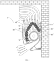
Classifications
-
- F—MECHANICAL ENGINEERING; LIGHTING; HEATING; WEAPONS; BLASTING
- F24—HEATING; RANGES; VENTILATING
- F24F—AIR-CONDITIONING; AIR-HUMIDIFICATION; VENTILATION; USE OF AIR CURRENTS FOR SCREENING
- F24F1/00—Room units for air-conditioning, e.g. separate or self-contained units or units receiving primary air from a central station
- F24F1/0007—Indoor units, e.g. fan coil units
-
- F—MECHANICAL ENGINEERING; LIGHTING; HEATING; WEAPONS; BLASTING
- F24—HEATING; RANGES; VENTILATING
- F24F—AIR-CONDITIONING; AIR-HUMIDIFICATION; VENTILATION; USE OF AIR CURRENTS FOR SCREENING
- F24F1/00—Room units for air-conditioning, e.g. separate or self-contained units or units receiving primary air from a central station
- F24F1/0007—Indoor units, e.g. fan coil units
- F24F1/0043—Indoor units, e.g. fan coil units characterised by mounting arrangements
- F24F1/0057—Indoor units, e.g. fan coil units characterised by mounting arrangements mounted in or on a wall
-
- F—MECHANICAL ENGINEERING; LIGHTING; HEATING; WEAPONS; BLASTING
- F24—HEATING; RANGES; VENTILATING
- F24F—AIR-CONDITIONING; AIR-HUMIDIFICATION; VENTILATION; USE OF AIR CURRENTS FOR SCREENING
- F24F1/00—Room units for air-conditioning, e.g. separate or self-contained units or units receiving primary air from a central station
- F24F1/0007—Indoor units, e.g. fan coil units
- F24F1/0011—Indoor units, e.g. fan coil units characterised by air outlets
-
- F—MECHANICAL ENGINEERING; LIGHTING; HEATING; WEAPONS; BLASTING
- F24—HEATING; RANGES; VENTILATING
- F24F—AIR-CONDITIONING; AIR-HUMIDIFICATION; VENTILATION; USE OF AIR CURRENTS FOR SCREENING
- F24F1/00—Room units for air-conditioning, e.g. separate or self-contained units or units receiving primary air from a central station
- F24F1/0007—Indoor units, e.g. fan coil units
- F24F1/0011—Indoor units, e.g. fan coil units characterised by air outlets
- F24F1/0014—Indoor units, e.g. fan coil units characterised by air outlets having two or more outlet openings
-
- F—MECHANICAL ENGINEERING; LIGHTING; HEATING; WEAPONS; BLASTING
- F24—HEATING; RANGES; VENTILATING
- F24F—AIR-CONDITIONING; AIR-HUMIDIFICATION; VENTILATION; USE OF AIR CURRENTS FOR SCREENING
- F24F1/00—Room units for air-conditioning, e.g. separate or self-contained units or units receiving primary air from a central station
- F24F1/0007—Indoor units, e.g. fan coil units
- F24F1/0059—Indoor units, e.g. fan coil units characterised by heat exchangers
- F24F1/0063—Indoor units, e.g. fan coil units characterised by heat exchangers by the mounting or arrangement of the heat exchangers
-
- F—MECHANICAL ENGINEERING; LIGHTING; HEATING; WEAPONS; BLASTING
- F24—HEATING; RANGES; VENTILATING
- F24F—AIR-CONDITIONING; AIR-HUMIDIFICATION; VENTILATION; USE OF AIR CURRENTS FOR SCREENING
- F24F11/00—Control or safety arrangements
- F24F11/89—Arrangement or mounting of control or safety devices
-
- F—MECHANICAL ENGINEERING; LIGHTING; HEATING; WEAPONS; BLASTING
- F24—HEATING; RANGES; VENTILATING
- F24F—AIR-CONDITIONING; AIR-HUMIDIFICATION; VENTILATION; USE OF AIR CURRENTS FOR SCREENING
- F24F13/00—Details common to, or for air-conditioning, air-humidification, ventilation or use of air currents for screening
-
- F—MECHANICAL ENGINEERING; LIGHTING; HEATING; WEAPONS; BLASTING
- F24—HEATING; RANGES; VENTILATING
- F24F—AIR-CONDITIONING; AIR-HUMIDIFICATION; VENTILATION; USE OF AIR CURRENTS FOR SCREENING
- F24F13/00—Details common to, or for air-conditioning, air-humidification, ventilation or use of air currents for screening
- F24F13/08—Air-flow control members, e.g. louvres, grilles, flaps or guide plates
-
- F—MECHANICAL ENGINEERING; LIGHTING; HEATING; WEAPONS; BLASTING
- F24—HEATING; RANGES; VENTILATING
- F24F—AIR-CONDITIONING; AIR-HUMIDIFICATION; VENTILATION; USE OF AIR CURRENTS FOR SCREENING
- F24F13/00—Details common to, or for air-conditioning, air-humidification, ventilation or use of air currents for screening
- F24F13/20—Casings or covers
-
- F—MECHANICAL ENGINEERING; LIGHTING; HEATING; WEAPONS; BLASTING
- F24—HEATING; RANGES; VENTILATING
- F24F—AIR-CONDITIONING; AIR-HUMIDIFICATION; VENTILATION; USE OF AIR CURRENTS FOR SCREENING
- F24F13/00—Details common to, or for air-conditioning, air-humidification, ventilation or use of air currents for screening
- F24F13/22—Means for preventing condensation or evacuating condensate
- F24F13/222—Means for preventing condensation or evacuating condensate for evacuating condensate
-
- F—MECHANICAL ENGINEERING; LIGHTING; HEATING; WEAPONS; BLASTING
- F24—HEATING; RANGES; VENTILATING
- F24F—AIR-CONDITIONING; AIR-HUMIDIFICATION; VENTILATION; USE OF AIR CURRENTS FOR SCREENING
- F24F2221/00—Details or features not otherwise provided for
- F24F2221/17—Details or features not otherwise provided for mounted in a wall
Definitions
- This application relates to the field of air conditioners, and more particularly to a wall-mounted air conditioner.
- an air inlet of a wall-mounted air conditioner is at its top.
- the wall-mounted air conditioner In order to meet a requirement for air inflow from the top, the wall-mounted air conditioner has to be at a large distance from an indoor top wall, resulting in low indoor space utilization and making the indoor space more cramped.
- the wall-mounted air conditioner in the related art has low heat exchange efficiency.
- some components in the air conditioner such as electric control components, pipelines, circuits, throttling components, etc.
- a side e.g., a left side and/or a right side
- the present invention aims to solve at least one of the technical problems existing in the related art. Accordingly, embodiments of the present invention propose a wall-mounted air conditioner.
- the wall-mounted air conditioner comprises a housing and a heat exchanger.
- An air duct is arranged in the housing, the air duct has an air inlet and an air outlet, and the air duct comprises an air inflow section and an air outflow section connected to each other, at least a part of the air inlet being on a front surface of the housing.
- the heat exchanger is arranged in the air duct.
- the air inflow section extends horizontally or obliquely forwards from the air outflow section, to define a first mounting space behind the air inflow section; and/or a part, adjacent to the air outlet, of the air outflow section extends downwards and forwards from a remaining part of the air outflow section, to define a second mounting space behind the air outflow section; and/or a third mounting space is defined between the air inflow section and the air outflow section.
- ambient air can enter the air duct substantially from the front of the housing.
- the ambient air can enter the air duct from the straight front of the housing, or from the top front of the housing, or from the bottom front of the housing.
- the ambient air can enter the air duct from at least two directions selected from the straight front of the housing, the top front of the housing, or from the bottom front of the housing.
- the ambient air does not necessarily enter the air duct directly above the housing.
- a distance between the wall-mounted air conditioner and an indoor top wall can be greatly decreased or even eliminated, and the utilization rate of indoor space can be improved, especially for indoor space (rooms) with lower heights, which can effectively reduce or eliminate a sense of crampedness of the indoor space.
- the wall-mounted air conditioner according to embodiments of the present invention has a very low requirement for mounting space. As long as the wall-mounted air conditioner can be accommodated in the mounting space, there is no need to leave an air inflow space above the wall-mounted air conditioner, which can expand the applicability of the wall-mounted air conditioner.
- the top space is often restricted and relatively narrow, which limits the air inflow volume due to the narrow top space.
- the air inflow volume of the wall-mounted air conditioner is not limited by the narrow space at the top. The air inflow from the front surface of the housing can effectively increase the air inflow volume and significantly increase the air flow volume through the heat exchanger, greatly enhancing the heat exchange efficiency of the heat exchanger.
- the air inlet since at least a part of the air inlet is located on the front surface of the housing, there is no need to mount a roughly inverted V-shaped heat exchanger below the air inlet, and it is unnecessary to mount a water receiving tray with a width greater than or equal to a width of the roughly inverted V-shaped heat exchanger at a lower end of the heat exchanger, to avoid failure in heat exchange of air with a part of the heat exchanger due to the part being obstructed by the water receiving tray. Since at least a part of the air inlet is located on the front surface of the housing, the water receiving tray will not prevent airflow from flowing to the heat exchanger. For example, the water receiving tray does not pass an airflow path to the heat exchanger, which can greatly improve the heat exchange efficiency of the heat exchanger. Optionally, the water receiving tray is located below the heat exchanger.
- the wall-mounted air conditioner in the embodiments of the present invention has advantages of easy installation, improved indoor space utilization, wide applicability, and high heat exchange efficiency.
- the wall-mounted air conditioner provides one or more of the first mounting space, the second mounting space and the third mounting space, which can be used to mount components that are originally mounted on a side (e.g., a left side and/or a right side) of a length direction of the air duct.
- electric control components, pipelines, circuits, throttling components and the like can be mounted in one or more of the first mounting space, the second mounting space, and the third mounting space.
- the wall-mounted air conditioner according to the embodiments of the present invention has advantages of high utilization rate of the internal space, compact structure, small length, low installation difficulty, and small space required for installation.
- the wall-mounted air conditioner further comprises a first component, a second component, and a third component, wherein one or more of the first component, second component, and the third component are mounted in any of the first mounting space, the second mounting space, and the third mounting space.
- the first component is mounted in the first mounting space
- the second component is mounted in the second mounting space
- the third component is mounted in the third mounting space.
- the first component is a throttling component
- the second component is air conditioner pipelines and/or wires
- the third component is an electric control component
- an air duct wall of the air inflow section comprises a first air inflow plate and a second air inflow plate
- an air duct wall of the air outflow section comprises a first air outflow plate and a second air outflow plate
- the third mounting space is defined among the second air inflow plate, the second air outflow plate, and a front plate of the housing
- the first mounting space is behind the first air inflow plate
- the second mounting space is behind the first air outflow plate.
- the second air inflow plate comprises a sunken part that forms a water receiving sink for receiving condensate water from the heat exchanger.
- a rear surface of the first air inflow plate and/or a rear surface the first air outflow plate is provided with a water tank having an opening facing upwards; the first mounting space is above the water tank and the second mounting space is below the water tank; and the water tank is arranged obliquely and communicated with the water receiving sink.
- the third mounting space is on a side of the sunken part facing away the water receiving sink.
- the first air outflow plate comprises a first flat plate portion adjacent to the air outlet
- the second air outflow plate comprises a second flat plate portion adjacent to the air outlet.
- a first intersection angle between the second flat plate portion and a centerline of the air outflow section is greater than 0 degree and less than or equal to 30 degrees; or a second intersection angle between the first flat plate portion and the second flat plate portion is greater than or equal to 5 degrees and less than or equal to 45 degrees.
- a third intersection angle between a centerline of the air inflow section and a centerline of the air outflow section is greater than or equal to 10 degrees and less than or equal to 85 degrees.
- a fourth intersection angle between a centerline of the air outflow section and a vertical upward direction is greater than or equal to 120 degrees and less than or equal to 155 degrees.
- the present invention is based on the inventors' discovery and understanding of the following facts and issues.
- an air inlet of a wall-mounted air conditioner 1' is located at its top, and the top of the wall-mounted air conditioner 1' has to be at a large distance from an indoor top wall 3, to define an air inflow space. Consequently, the wall-mounted air conditioner 1' cannot be arranged tightly against the indoor top wall 3.
- a heat exchanger 10' of the wall-mounted air conditioner 1' is arranged around a cross-flow fan wheel 20'. Specifically, a first part 11' of the heat exchanger 10', which forms a roughly inverted V-shape, is located above the cross-flow fan wheel 20', and a second part 12' of the heat exchanger 10' is located in front of the cross-flow fan wheel 20'.
- a water receiving tray 30' is provided below a rear lower end 111' of the first part 11'.
- the water receiving plate 30' is opposite to the rear lower end 111' of the first part 11' in an up-down direction and is located between the rear lower end 111' of the first part 11' and the cross-flow fan wheel 20'.
- the inventors have realized that the rear lower end 111' of the first part 11' is obstructed by the water receiving tray 30', such that the rear lower end 111' of the first part 11' does not exchange heat with air, resulting in waste and lowering heat transfer efficiency.
- An inlet air duct 50' is formed between the second part 12' and a front panel 40' of the wall-mounted air conditioner 1'.
- the inventors have realized that since most of the space in a front-rear direction of the wall-mounted air conditioner 1' is occupied by the heat exchanger 10', the cross-flow fan wheel 20' and a volute 60', the inlet air duct 50' is relatively narrow, resulting in a small air flow volume through the inlet air duct 50' and a low heat transfer efficiency of the second part 12'.
- the wall-mounted air conditioner 1 comprises a housing 10, a heat exchanger 20, and an air duct 30.
- the air duct 30 is located inside the housing 10, and the heat exchanger 20 is located inside the air duct 30.
- the air duct 30 comprises an air inflow section 313 and an air outflow section 314 connected to each other.
- the air duct 30 has an air inlet 311 and an air outlet 312. The air inlet 311 is located in the air inflow section 313, and the air outlet 312 is located in the air outflow section 314.
- the front surface 11 of the housing 10 is a surface that can be seen by a horizontal backward line of sight, that is, a surface of the housing 10 that can be seen by the horizontal backward line of sight is the front surface 11 of the housing 10.
- a surface of the housing 10 that the observer can see is the front surface 11 of the housing 10.
- a front-rear direction is shown by arrow A in FIG. 1
- an up-down direction is shown by arrow B in FIG. 1
- the wall-mounted air conditioner 1 is mounted on a wall surface 2.
- a direction away from the wall surface 2 in the horizontal direction represents a forward direction
- a direction away from the wall surface 2 in the horizontal direction represents a rearward direction.
- the housing 10 has a mounting space therein. There may be one or more kinds of mounting spaces.
- the air inflow section 313 extends horizontally or obliquely forwards from the air outflow section 314 to define a first mounting space 50 behind the air inflow section 313.
- the air inflow section 313 extends horizontally or obliquely forwards from its connection with the air outflow section 314, defining a mounting space, i.e., the first mounting space 50, behind the air inflow section 313, which is configured to mount components of the air conditioner.
- a part, adjacent to the air outlet 312, of the air outflow section 314 extends downwards and forwards from a remaining part of the air outflow section 314, to define a second mounting space 60 behind the air outflow section 314.
- the air outflow section 314 comprises the part adjacent to the air outlet 312 and the remaining part except for that part.
- the part, adjacent to the air outlet 312, of the air outflow section 314 extends downwards and forwards from its connection with the remaining part, defining a mounting space i.e., the second mounting space 60, behind the air outflow section 314, which is configured to mount components of the air conditioner.
- a third mounting space 70 is defined between the air inflow section 313 and the air outflow section 314. It should be noted that the third mounting space 70 is located in front of at least a part of the air duct 30 and can be configured to mount components of the air conditioner.
- ambient air can enter the air duct substantially from the front of the housing.
- the ambient air can enter the air duct from the straight front of the housing, or from the top front of the housing, or from the bottom front of the housing.
- the ambient air can enter the air duct from at least two directions selected from the straight front of the housing, the top front of the housing, or from the bottom front of the housing.
- the ambient air does not necessarily enter the air duct directly above the housing.
- a distance between the wall-mounted air conditioner and an indoor top wall can be greatly decreased or even eliminated, and the utilization rate of indoor space can be improved, especially for indoor space (rooms) with lower heights, which can effectively reduce or eliminate a sense of crampedness of the indoor space.
- the wall-mounted air conditioner according to embodiments of the present invention has a very low requirement for mounting space. As long as the wall-mounted air conditioner can be accommodated in the mounting space, there is no need to leave an air inflow space above the wall-mounted air conditioner, which can expand the applicability of the wall-mounted air conditioner.
- the air inlet 311 is located on the front surface, inclined upwards towards the wall surface 2 (which can be understood as a mounting surface) relative to a vertical surface. In this way, when a user standing on the ground of the room, the user cannot see the interior of the housing 10 (the wall-mounted air conditioner 1) through the air inlet 311, and internal structures of the housing 10 (the wall-mounted air conditioner 1) are not exposed to the user, which can improve the user's visual comfort.
- the top space is often restricted and relatively narrow, which limits the air inflow volume due to the narrow top space.
- the air inflow volume of the wall-mounted air conditioner is not limited by the narrow space at the top. The air inflow from the front surface of the housing can effectively increase the air inflow volume and significantly increase the air flow volume through the heat exchanger, greatly enhancing the heat exchange efficiency of the heat exchanger.
- the air inlet since at least a part of the air inlet is located on the front surface of the housing, there is no need to mount a roughly inverted V-shaped heat exchanger below the air inlet, and it is unnecessary to mount a water receiving tray with a width greater than or equal to a width of the roughly inverted V-shaped heat exchanger at a lower end of the heat exchanger, to avoid failure in heat exchange of air with a part of the heat exchanger due to the part being obstructed by the water receiving tray. Since at least a part of the air inlet is located on the front surface of the housing, the water receiving tray will not prevent airflow from flowing to the heat exchanger. For example, the water receiving tray does not pass an airflow path to the heat exchanger, which can greatly improve the heat exchange efficiency of the heat exchanger. Optionally, the water receiving tray is located below the heat exchanger.
- the wall-mounted air conditioner in the embodiments of the present invention has advantages of easy installation, improved indoor space utilization, wide applicability, and high heat exchange efficiency.
- the wall-mounted air conditioner provides one or more of the first mounting space, the second mounting space and the third mounting space, which can be used to mount components that are originally mounted on a side (e.g., a left side and/or a right side) of a length direction of the air duct.
- electric control components, pipelines, circuits, throttling components and the like can be mounted in one or more of the first mounting space, the second mounting space, and the third mounting space.
- the wall-mounted air conditioner according to the embodiments of the present invention has advantages of high utilization rate of the internal space, compact structure, small length, low installation difficulty, and small space required for installation.
- the wall-mounted air conditioner 1 is mounted on the wall surface 2 indoors.
- the wall-mounted air conditioner 1 comprises the housing 10, the heat exchanger 20, the air duct 30 inside the housing 10, and a fan wheel 40 in the air duct 30.
- the housing 10 comprises a front plate 111, and the air inlet 311 is on the front plate 111.
- a distance between a top surface of the housing 10 and the indoor top wall 3 is less than or equal to 20 centimeters.
- a minimum distance between the housing 10 and the indoor top wall 3 in the up-down direction is less than or equal to 20 centimeters.
- the distance between the top surface of the housing 10 and the indoor top wall 3 is less than or equal to 15 centimeters.
- the distance between the top surface of the housing 10 and the indoor top wall 3 is less than or equal to 10 centimeters.
- the distance between the top surface of the housing 10 and the indoor top wall 3 is less than or equal to 8 centimeters.
- the distance between the top surface of the housing 10 and the indoor top wall 3 is less than or equal to 5 centimeters.
- the top surface of the housing 10 is in contact with the indoor top wall 3, i.e., the distance between the top surface of the housing 10 and the indoor top wall 3 is equal to 0 centimeter. Hence, the utilization rate of indoor space can be further improved.
- the air duct 30 comprises the air inflow section 313 and the air outflow section 314.
- the air inflow section 313 forms an inlet air duct 3136
- the air outflow section 314 forms an outlet air duct 3143.
- the air inlet 311 of the air duct 30 is at an end of the inlet air duct 3136
- the air outlet 312 of the air duct 30 is at an end of the outlet air duct 3143.
- the heat exchanger 20 is arranged inside the inlet air duct 3136 and at the air inlet 311.
- the heat exchanger 20 is corresponding to the air inlet 311 to exchange heat with air entering the inlet air duct 3136 from the air inlet 311.
- a part of the fan wheel 40 is located in the inlet air duct 3136, and another part of the fan wheel 40 is located in the outlet air duct 3143.
- the fan wheel 40 is used to generate air exhaust force, allowing air entering the inlet air duct 3136 from the air inlet 311 to subsequently enter the outlet air duct 3143 through the fan wheel 40, and finally be discharged from the air outlet.
- the arrangement of the fan wheel 40 in the air duct 30 can increase the flow volume and velocity of air passing through the heat exchanger 20, to further improve the heat exchange efficiency of the heat exchanger 20 and the wall-mounted air conditioner 1.
- the air inflow section 313 obliquely extends forwards and upwards from its connection with the air outflow section 314.
- the first mounting space 50 is behind the air inflow section 313. It can be understood that the first mounting space 50 is in front of the wall surface 2.
- the air inflow section 313 may also extend horizontally forward from its connection with the air outflow section 314, or the air inflow section 313 may also extend downwards from its connection with the air outflow section 314.
- the air inflow section 313 obliquely extends forwards and upwards from its connection with the air outflow section 314 to make the structure of the wall-mounted air conditioner 1 more reasonable.
- the air outlet 312 is located at a lower part of the housing 10.
- the second mounting space 60 is behind the air outflow section 314. It can be understood that the second mounting space 60 is in front of the wall surface 2.
- the above arrangement of the air inflow section 313 and the air outflow section 314 causes the air duct 30 to be substantially V-shaped with an opening facing forwards, and the air inflow section 313 is above the part, adjacent to the air outlet 312, of the air outflow section 313.
- the third mounting space 70 is between the air inflow section 313 and the air outflow section 314, i.e., in the opening of the substantially V-shaped air duct 30.
- the first mounting space 50, the second mounting space 60, and the third mounting space 70 can all be configured to mount components of the air conditioner. That is, the components of the air conditioner can be mounted in at least one of the first mounting space 50, the second mounting space 60, and the third mounting space 70.
- the wall-mounted air conditioner 1 comprises a first component, a second component, and a third component.
- One or more of the first component, the second component, and the third component are mounted in any of the first mounting space 50, the second mounting space 60, and the third mounting space 70. That is, the first mounting space 50, the second mounting space 60, and the third mounting space 70 can mount one or more components of the air conditioner.
- the first component is mounted in the first mounting space 50
- the second component is mounted in the second mounting space 60
- the third component is mounted in the third mounting space 70.
- the first component is a throttling component 91; the second component comprises air conditioner pipelines 92 and/or wires; and the third component is an electric control component 93.
- the throttling component 91 is mounted in the first mounting space 50, the air conditioning pipelines 92 are mounted in the second mounting space 60, and the electric control component 93 is mounted in the third mounting space 70.
- an air duct wall of the air inflow section 313 comprises a first air inflow plate 3131 and a second air inflow plate 3132, and the inlet air duct 3136 is formed between the first air inflow plate 3131 and the second air inflow plate 3132.
- An air duct wall of the air outflow section 314 comprises a first air outflow plate 3141 and a second air outflow plate 3142, and the outlet air duct 3143 is formed between the first air outflow plate 3141 and the second air outflow plate 3142.
- the first air outflow plate 3141 is a volute tongue structure
- the second air outflow plate 3142 is a volute wheel structure.
- the first mounting space 50 is behind the first air inflow plate 3131, and the second mounting space 60 is behind the first air outflow plate 3141.
- the third mounting space 70 is defined among the second air inflow plate 3132, the second air outflow plate 3142, and the front plate 111 of the housing 10.
- the third mounting space 70 is defined among a side surface 31321 of the second air inflow plate 3132 away from the inlet air duct 3136, a side surface 31421 of the second air outflow plate 3142 away from the outlet air duct 3143, and a rear surface 1110 of the front plate 111.
- the first mounting space 50 is in an upper and rear position within the wall-mounted air conditioner 1
- the second mounting space 60 is in a lower and rear position within the wall-mounted air conditioner 1.
- the third mounting space 70 is in a front and lower position within the internal space of the housing 10.
- the housing 10 comprises a top plate 112 and a bottom plate 113.
- a first end of the top plate 112 is connected to the first air inflow plate 3131 and extends backwards; and a second end of the top plate 112 abuts against the wall surface 2.
- the first mounting space 50 is below the top plate 112.
- a first end of the bottom plate 113 is connected to the first air outflow plate 3141 and extends backwards; and a second end of the bottom plate 113 abuts against the wall surface 2.
- the second mounting space 60 is above the bottom plate 113.
- both the top plate 112 and the bottom plate 113 extend along a horizontal plane.
- the front plate 111 is a curved plate protruding forwards, and the front plate 111 comprises an upper plate portion 1111 and a lower plate portion 1112.
- the upper plate portion 1111 is an upper portion of the front plate 111
- the lower plate portion 1112 is a lower portion of the front plate 111
- the upper plate portion 1111 is above the lower plate portion 1112.
- the air inlet 311 is on the upper plate portion 1111; the third mounting space 70 is behind the lower plate portion 1112; and the third mounting space 70 is below the air inlet 311.
- the heat exchanger 20 is fitted at the air inlet of the air inflow section 313; an upper end of the heat exchanger 20 cooperates with the first air inflow plate 3131, and a first sealing structure (not shown) is provided between the upper end of the heat exchanger 20 and the first air inflow plate 3131; a lower end of the heat exchanger 20 cooperates with the second air inflow plate 3132, and a second sealing structure (not shown) is provided between the lower end of the heat exchanger 20 and the second air inflow plate 3132.
- the first sealing structure and the second sealing structure are used for sealing to prevent air, which has not undergone heat exchange with the heat exchanger 20, from entering the inlet air duct 3136 via a gap between the heat exchanger 20 and the first air inflow plate 3131 or between the heat exchanger 20 and the second air inflow plate 3132, which may otherwise affect a cooling effect of the air conditioner.
- the first sealing structure and the second sealing structure are sealing foam.
- the second air inflow plate 3132 comprises a sunken part 3133 that forms a water receiving sink 3134 for receiving the condensate water from the heat exchanger 20, as shown in FIGS. 1 and 2 .
- the water receiving sink 3134 is on a side of the sunken part 3133 close to the inlet air duct 3136.
- the sunken part 3133 is formed in such a way that a part of the second air inflow plate 3132 is recessed in a direction away from the inlet air duct 3136.
- the sunken part 3133 may also be seen as a part of the second air inflow plate 3132 protruding into the third mounting space 70.
- the third mounting space 70 is on a side of the sunken part 3133 facing away the water receiving sink 3134. Since the sunken part 3133 forms the water receiving sink 3134, the sunken part 3133 may also be called a water receiving tray.
- the water receiving sink 3134 has an opening facing upwards, and the water receiving sink 3134 has a certain depth in the up-down direction.
- the water receiving sink 3134 is behind the lower end of the heat exchanger 20, i.e., behind the second sealing structure, and the water receiving sink 3134 is also below the heat exchanger 20 to effectively receive the condensate water of the heat exchanger 20.
- a part of the first air inflow plate 3131 is recessed outwards to form an avoidance groove 3135 that is located behind the upper end of the heat exchanger 20, i.e., behind the first sealing structure.
- the avoidance groove 3135 is used to avoid the condensate water generated by the heat exchanger 20 during the heat exchange process and to prevent the condensate water from flowing into the air outflow section 314 along the first air inflow plate 3131.
- a part, adjacent to the air outflow section 314, of the first air inflow plate 3131 is recessed outwards to form the avoidance groove 3135.
- the avoidance groove 3135 is formed in such a way that a part of the second air inflow plate 3132 is recessed in a direction away from the inlet air duct 3136, and the avoidance groove 3135 may also be seen as a part of the second air inflow plate 3132 protruding into the first mounting space 50.
- a rear surface of the first air inflow plate 3131 and/or the first air outflow plate 3141 is provided with a water tank 80 having an opening facing upwards; the first mounting space 50 is above the water tank 80 and the second mounting space 60 is below the water tank 80; and the water tank 80 is arranged obliquely and communicated with the water receiving sink 3134.
- the water tank 80 is used to receive condensate water formed on the rear surface of the first air inflow plate 3131 and/or the first air outflow plate 3141, and is also used to receive condensate water from the throttling component 91 mounted in the first mounting space 50.
- the water in the water tank 80 will converge into the water receiving sink 3134 and then be discharged together.
- the oblique arrangement of the water tank 80 means that the water tank 80 is arranged obliquely in its length direction.
- the first air inflow plate 3131 and the first air outflow plate 3141 are connected to form an integrated first wall, while the second air inflow plate 3132 and the second air outflow plate 3142 are connected to form an integrated second wall.
- the water tank 80 is arranged on a rear surface of the first wall. Further, the water tank 80 is at a rearmost position on the rear surface of the first wall to better receive the condensate water.
- the water tank 80 extends along a length direction of the wall-mounted air conditioner 1 and is obliquely arranged.
- the water receiving sink 3134 also extends along the length direction of the wall-mounted air conditioner 1 and is obliquely arranged.
- a tilt direction of the water receiving sink 3134 is the same as a tilt direction of the water tank 80.
- the length direction of the wall-mounted air conditioner 1 is consistent with a length direction of the air duct 30.
- the length direction of the air duct 30 is shown by arrow C in FIG. 3 .
- a lower end of the water tank 80 is connected to a lower end of the water receiving sink 3134, so that the water in the water tank 80 will converge into the water receiving sink 3134.
- the lower end of the water receiving sink 3134 is connected to a drainage outlet inside the wall-mounted air conditioner 1, so that the water in the water tank 80 and the water receiving sink 3134 can be discharged from the drainage outlet.
- the first air outflow plate 3141 comprises a first flat plate portion 3144 adjacent to the air outlet 312, and the second air outflow plate 3142 comprises a second flat plate portion 3145 adjacent to the air outlet 312. Inner sides of respective projections of the first flat plate portion 3144 and the second flat plate portion 3145 are both straight lines.
- a first intersection angle ⁇ 1 between the second flat plate portion 3145 and a centerline of the air outflow section 314 is greater than 0 degree and less than or equal to 30 degrees.
- the second mounting space 60 and the third mounting space 70 are large enough to house components, which are originally mounted on a side (such as a left side and/or a right side) of the air duct 30 in the length direction.
- the length of the wall-mounted air conditioner 1 can be effectively decreased, and the installation difficulty and space required for the wall-mounted air conditioner 1 can be reduced.
- a left-right direction is shown by arrow E in FIG. 3 .
- the first intersection angle ⁇ 1 is greater than or equal to 1 degree and less than or equal to 25 degrees. Alternatively, the first intersection angle ⁇ 1 is greater than or equal to 2 degrees and less than or equal to 20 degrees. Alternatively, the first intersection angle ⁇ 1 is greater than or equal to 3 degrees and less than or equal to 10 degrees.
- the air flow volume inside the outlet air duct 3143 can be increased, and the capacities of the second mounting space 60 and the third mounting space 70 can be enlarged, further improving the cooling and heating effect of the wall-mounted air conditioner 1, further decreasing the length of the wall-mounted air conditioner 1, and further reducing the installation difficulty and space required for the wall-mounted air conditioner 1.
- the first intersection angle ⁇ 1 may be but is not limited to 1 degree, 2 degrees, 3 degrees, 4 degrees, 5 degrees, 6 degrees, 7 degrees, 8 degrees, 9 degrees, 10 degrees, 15 degrees, 20 degrees, 25 degrees, or 30 degrees.
- a second intersection angle ⁇ 2 between the first flat plate portion 3144 and the second flat plate portion 3145 is greater than or equal to 5 degrees and less than or equal to 45 degrees. It is possible to reduce the space occupied by the outlet air duct 3143 while ensuring the air flow volume inside the outlet air duct 3143 (the air outflow volume of the outlet air duct 3143), so that the second mounting space 60 and the third mounting space 70 are large enough to house the components, which are originally mounted on the side (such as the left side and/or the right side) of the air duct 30 in the length direction.
- the length of the wall-mounted air conditioner 1 can be effectively decreased, and the installation difficulty and space required for the wall-mounted air conditioner 1 can be reduced.
- the second intersection angle ⁇ 2 is greater than or equal to 10 degrees and less than or equal to 40 degrees. Alternatively, the second intersection angle ⁇ 2 is greater than or equal to 10 degrees and less than or equal to 30 degrees. Alternatively, the second intersection angle ⁇ 2 is greater than or equal to 10 degrees and less than or equal to 20 degrees.
- the air flow volume inside the outlet air duct 3143 can be increased, and the capacities of the second mounting space 60 and the third mounting space 70 can be enlarged, further improving the cooling and heating effect of the wall-mounted air conditioner 1, further decreasing the length of the wall-mounted air conditioner 1, and further reducing the installation difficulty and space required for the wall-mounted air conditioner 1.
- the second intersection angle ⁇ 2 may be but is not limited to 5 degrees, 10 degrees, 11 degrees, 12 degrees, 13 degrees, 14 degrees, 15 degrees, 16 degrees, 17 degrees, 18 degrees, 19 degrees, 20 degrees, 25 degrees, 30 degrees, 35 degrees, 40 degrees, or 45 degrees.
- a third intersection angle ⁇ 3 between a centerline L1 of the air inflow section 313 and a centerline L2 of the air outflow section 314 is greater than or equal to 10 degrees and less than or equal to 85 degrees. It is possible to avoid significant changes in a flow direction of air in the air duct 30, in order to reduce flow resistance against the air and allow the air to flow smoothly in the air duct 30, further improving the cooling and heating effect of the wall-mounted air conditioner 1.
- the third intersection angle ⁇ 3 is greater than or equal to 20 degrees and less than or equal to 80 degrees. Alternatively, the third intersection angle ⁇ 3 is greater than or equal to 40 degrees and less than or equal to 75 degrees. Alternatively, the third intersection angle ⁇ 3 is greater than or equal to 60 degrees and less than or equal to 75 degrees. Alternatively, the third intersection angle ⁇ 3 is greater than or equal to 70 degrees and less than or equal to 75 degrees. Consequently, the air can flow more smoothly in the air duct 30 and the cooling and heating effect of the wall-mounted air conditioner 1 can be further improved.
- the third intersection angle ⁇ 3 may be but is not limited to 10 degrees, 15 degrees, 20 degrees, 25 degrees, 30 degrees, 35 degrees, 40 degrees, 45 degrees, 50 degrees, 55 degrees, 60 degrees, 65 degrees, 70 degrees, 71 degrees, 72 degrees, 73 degrees, 74 degrees, 75 degrees, 76 degrees, 77 degrees, 78 degrees, 79 degrees, 80 degrees, or 85 degrees.
- a fourth intersection angle ⁇ 4 between the centerline L2 of the air outflow section 314 and a vertical upward direction is greater than or equal to 120 degrees and less than or equal to 155 degrees.
- the air leaving the outlet air duct 3143 can flow downwards and forwards, that is, the wall-mounted air conditioner 1 can discharge cold air (hot air) downwards and forwards, which can further improve the cooling and heating effect of the wall-mounted air conditioner 1.
- the vertical upward direction is shown by an upward arrow B in FIG. 1 .
- the fourth intersection angle ⁇ 4 is greater than or equal to 130 degrees and less than or equal to 150 degrees.
- the fourth intersection angle ⁇ 4 is greater than or equal to 140 degrees and less than or equal to 145 degrees.
- the flow direction of the cold air (hot air) discharged from the wall-mounted air conditioner 1 can be further optimized to improve the cooling and heating effect of the wall-mounted air conditioner 1.
- the fourth intersection angle ⁇ 4 may be but is not limited to 120 degrees, 125 degrees, 130 degrees, 135 degrees, 140 degrees, 141 degrees, 142 degrees, 143 degrees, 144 degrees, 145 degrees, 150 degrees, or 155 degrees.
- first and second are used herein for purposes of description and are not intended to indicate or imply relative importance or significance or to imply the number of indicated technical features.
- the feature defined with “first” and “second” may comprise one or more of this feature.
- the term “a plurality of” means at least two, such as two or three, unless specified otherwise.
- the terms “mounted,” “connected,” “coupled,” “fixed” and the like are used broadly, and may be, for example, fixed connections, detachable connections, or integral connections; may also be mechanical or electrical connections; may also be direct connections or indirect connections via intervening structures; may also be inner communication or interaction of two elements, which can be understood by those skilled in the art according to specific situations.
- a structure in which a first feature is "on" or “below” a second feature may include an embodiment in which the first feature is in direct contact with the second feature, and may also include an embodiment in which the first feature and the second feature are not in direct contact with each other, but are contacted via an additional feature formed therebetween.
- a first feature "on,” “above,” or “on top of” a second feature may include an embodiment in which the first feature is right or obliquely “on,” “above,” or “on top of” the second feature, or just means that the first feature is at a height higher than that of the second feature; while a first feature “below,” “under,” or “on bottom of” a second feature may include an embodiment in which the first feature is right or obliquely “below,” “under,” or “on bottom of” the second feature, or just means that the first feature is at a height lower than that of the second feature.
Landscapes
- Engineering & Computer Science (AREA)
- Chemical & Material Sciences (AREA)
- Combustion & Propulsion (AREA)
- Mechanical Engineering (AREA)
- General Engineering & Computer Science (AREA)
- Physics & Mathematics (AREA)
- Thermal Sciences (AREA)
- Air Filters, Heat-Exchange Apparatuses, And Housings Of Air-Conditioning Units (AREA)
Abstract
Description
- This application claims priority to and benefits of
Chinese Patent Application No. 202110610656.5, filed on June 1, 2021 - This application relates to the field of air conditioners, and more particularly to a wall-mounted air conditioner.
- In the related art, an air inlet of a wall-mounted air conditioner is at its top. In order to meet a requirement for air inflow from the top, the wall-mounted air conditioner has to be at a large distance from an indoor top wall, resulting in low indoor space utilization and making the indoor space more cramped. Moreover, the wall-mounted air conditioner in the related art has low heat exchange efficiency. In addition, some components in the air conditioner (such as electric control components, pipelines, circuits, throttling components, etc.) are usually mounted on a side (e.g., a left side and/or a right side) of a length direction of an air duct, which may lengthen the air conditioner's body and increase the installation difficulty.
- The present invention aims to solve at least one of the technical problems existing in the related art. Accordingly, embodiments of the present invention propose a wall-mounted air conditioner.
- The wall-mounted air conditioner according to embodiments of the present invention comprises a housing and a heat exchanger. An air duct is arranged in the housing, the air duct has an air inlet and an air outlet, and the air duct comprises an air inflow section and an air outflow section connected to each other, at least a part of the air inlet being on a front surface of the housing. The heat exchanger is arranged in the air duct. The air inflow section extends horizontally or obliquely forwards from the air outflow section, to define a first mounting space behind the air inflow section; and/or a part, adjacent to the air outlet, of the air outflow section extends downwards and forwards from a remaining part of the air outflow section, to define a second mounting space behind the air outflow section; and/or a third mounting space is defined between the air inflow section and the air outflow section.
- According to the present invention, since at least a part of the air inlet of the wall-mounted air conditioner is on the front surface of the housing, ambient air (air inflow) can enter the air duct substantially from the front of the housing. For example, the ambient air (air inflow) can enter the air duct from the straight front of the housing, or from the top front of the housing, or from the bottom front of the housing. In addition, the ambient air can enter the air duct from at least two directions selected from the straight front of the housing, the top front of the housing, or from the bottom front of the housing.
- That is, the ambient air does not necessarily enter the air duct directly above the housing. In such a way, a distance between the wall-mounted air conditioner and an indoor top wall can be greatly decreased or even eliminated, and the utilization rate of indoor space can be improved, especially for indoor space (rooms) with lower heights, which can effectively reduce or eliminate a sense of crampedness of the indoor space.
- Therefore, the wall-mounted air conditioner according to embodiments of the present invention has a very low requirement for mounting space. As long as the wall-mounted air conditioner can be accommodated in the mounting space, there is no need to leave an air inflow space above the wall-mounted air conditioner, which can expand the applicability of the wall-mounted air conditioner.
- Moreover, in a scenario of air inflow from the top, the top space is often restricted and relatively narrow, which limits the air inflow volume due to the narrow top space. In the technical solutions of this application, since at least a part of the air inlet is located on the front surface of the housing, the air entering the air duct through the air inlet can directly flow through the heat exchanger for sufficient heat exchange with the heat exchanger. That is, the air inflow volume of the wall-mounted air conditioner is not limited by the narrow space at the top. The air inflow from the front surface of the housing can effectively increase the air inflow volume and significantly increase the air flow volume through the heat exchanger, greatly enhancing the heat exchange efficiency of the heat exchanger.
- In the present invention, since at least a part of the air inlet is located on the front surface of the housing, there is no need to mount a roughly inverted V-shaped heat exchanger below the air inlet, and it is unnecessary to mount a water receiving tray with a width greater than or equal to a width of the roughly inverted V-shaped heat exchanger at a lower end of the heat exchanger, to avoid failure in heat exchange of air with a part of the heat exchanger due to the part being obstructed by the water receiving tray. Since at least a part of the air inlet is located on the front surface of the housing, the water receiving tray will not prevent airflow from flowing to the heat exchanger. For example, the water receiving tray does not pass an airflow path to the heat exchanger, which can greatly improve the heat exchange efficiency of the heat exchanger. Optionally, the water receiving tray is located below the heat exchanger.
- Therefore, the wall-mounted air conditioner in the embodiments of the present invention has advantages of easy installation, improved indoor space utilization, wide applicability, and high heat exchange efficiency.
- In addition, the wall-mounted air conditioner according to the embodiments of the present invention provides one or more of the first mounting space, the second mounting space and the third mounting space, which can be used to mount components that are originally mounted on a side (e.g., a left side and/or a right side) of a length direction of the air duct. For example, electric control components, pipelines, circuits, throttling components and the like can be mounted in one or more of the first mounting space, the second mounting space, and the third mounting space. As a result, the internal space utilization efficiency and integration of the wall-mounted air conditioner; the structure of the wall-mounted air conditioner becomes more compact and reasonable; the length of the wall-mounted air conditioner can be decreased, the installation difficulty and space required for the wall-mounted air conditioner can be reduced.
- Therefore, the wall-mounted air conditioner according to the embodiments of the present invention has advantages of high utilization rate of the internal space, compact structure, small length, low installation difficulty, and small space required for installation.
- In some embodiments, the wall-mounted air conditioner further comprises a first component, a second component, and a third component, wherein one or more of the first component, second component, and the third component are mounted in any of the first mounting space, the second mounting space, and the third mounting space.
- In some embodiments, the first component is mounted in the first mounting space, the second component is mounted in the second mounting space, and the third component is mounted in the third mounting space.
- In some embodiments, the first component is a throttling component; the second component is air conditioner pipelines and/or wires; and the third component is an electric control component.
- In some embodiments, an air duct wall of the air inflow section comprises a first air inflow plate and a second air inflow plate, and an air duct wall of the air outflow section comprises a first air outflow plate and a second air outflow plate; the third mounting space is defined among the second air inflow plate, the second air outflow plate, and a front plate of the housing; the first mounting space is behind the first air inflow plate, and the second mounting space is behind the first air outflow plate.
- In some embodiments, the second air inflow plate comprises a sunken part that forms a water receiving sink for receiving condensate water from the heat exchanger.
- In some embodiments, a rear surface of the first air inflow plate and/or a rear surface the first air outflow plate is provided with a water tank having an opening facing upwards; the first mounting space is above the water tank and the second mounting space is below the water tank; and the water tank is arranged obliquely and communicated with the water receiving sink.
- In some embodiments, the third mounting space is on a side of the sunken part facing away the water receiving sink.
- In some embodiments, the first air outflow plate comprises a first flat plate portion adjacent to the air outlet, and the second air outflow plate comprises a second flat plate portion adjacent to the air outlet. A first intersection angle between the second flat plate portion and a centerline of the air outflow section is greater than 0 degree and less than or equal to 30 degrees; or a second intersection angle between the first flat plate portion and the second flat plate portion is greater than or equal to 5 degrees and less than or equal to 45 degrees.
- In some embodiments, a third intersection angle between a centerline of the air inflow section and a centerline of the air outflow section is greater than or equal to 10 degrees and less than or equal to 85 degrees.
- In some embodiments, a fourth intersection angle between a centerline of the air outflow section and a vertical upward direction is greater than or equal to 120 degrees and less than or equal to 155 degrees.
- Additional aspects and advantages of embodiments of the present invention will be given in part in the following descriptions, become apparent in part from the following descriptions, or be learned from the practice of the embodiments of the present invention.
-
-
FIG. 1 is a sectional view of a wall-mounted air conditioner according to embodiments of the present invention. -
FIG. 2 is a sectional view of a wall-mounted air conditioner according to embodiments of the present invention. -
FIG. 3 is a schematic view of a wall-mounted air conditioner according to embodiments of the present invention. -
FIG. 4 is a sectional view of a wall-mounted air conditioner in the related art. -
- wall-mounted
air conditioner 1,wall surface 2, top wall 3, -
housing 10,front surface 11,front plate 111,rear surface 1110 offront plate 111,upper plate portion 1111,lower plate portion 1112,top plate 112,bottom plate 113,heat exchanger 20,air duct 30,air inlet 311,air outlet 312, -
air inflow section 313, firstair inflow plate 3131, secondair inflow plate 3132,side surface 31321,sunken part 3133,water receiving sink 3134,avoidance groove 3135,inlet air duct 3136, -
air outflow section 314, firstair outflow plate 3141, secondair outflow plate 3142,side surface 31421, outlet air duct 3143, firstflat plate portion 3144, secondflat plate portion 3145, -
fan wheel 40,first mounting space 50,second mounting space 60,third mounting space 70,water tank 80,throttling component 91,air conditioner pipeline 92,electric control component 93, - centerline L1 of air inflow section, centerline L2 of air outflow section.
- Embodiments of the present invention will be described in detail below, and examples of the embodiments will be shown in the accompanying drawings. The embodiments described below are exemplary and are intended to explain the present invention rather than limit the present invention.
- The present invention is based on the inventors' discovery and understanding of the following facts and issues.
- In the related art, as shown in
FIG. 4 , an air inlet of a wall-mounted air conditioner 1' is located at its top, and the top of the wall-mounted air conditioner 1' has to be at a large distance from an indoor top wall 3, to define an air inflow space. Consequently, the wall-mounted air conditioner 1' cannot be arranged tightly against the indoor top wall 3. A heat exchanger 10' of the wall-mounted air conditioner 1' is arranged around a cross-flow fan wheel 20'. Specifically, a first part 11' of the heat exchanger 10', which forms a roughly inverted V-shape, is located above the cross-flow fan wheel 20', and a second part 12' of the heat exchanger 10' is located in front of the cross-flow fan wheel 20'. - A water receiving tray 30' is provided below a rear lower end 111' of the first part 11'. The water receiving plate 30' is opposite to the rear lower end 111' of the first part 11' in an up-down direction and is located between the rear lower end 111' of the first part 11' and the cross-flow fan wheel 20'. The inventors have realized that the rear lower end 111' of the first part 11' is obstructed by the water receiving tray 30', such that the rear lower end 111' of the first part 11' does not exchange heat with air, resulting in waste and lowering heat transfer efficiency.
- An inlet air duct 50' is formed between the second part 12' and a front panel 40' of the wall-mounted air conditioner 1'. However, the inventors have realized that since most of the space in a front-rear direction of the wall-mounted air conditioner 1' is occupied by the heat exchanger 10', the cross-flow fan wheel 20' and a volute 60', the inlet air duct 50' is relatively narrow, resulting in a small air flow volume through the inlet air duct 50' and a low heat transfer efficiency of the second part 12'.
- A wall-mounted
air conditioner 1 according to embodiments of the present invention will be described below according toFIGS. 1 to 3 . As shown inFIG. 1 , the wall-mountedair conditioner 1 comprises ahousing 10, aheat exchanger 20, and anair duct 30. Theair duct 30 is located inside thehousing 10, and theheat exchanger 20 is located inside theair duct 30. Theair duct 30 comprises anair inflow section 313 and anair outflow section 314 connected to each other. Theair duct 30 has anair inlet 311 and anair outlet 312. Theair inlet 311 is located in theair inflow section 313, and theair outlet 312 is located in theair outflow section 314. - At least a part of the
air inlet 311 is located on afront surface 11 of thehousing 10. Thefront surface 11 of thehousing 10 is a surface that can be seen by a horizontal backward line of sight, that is, a surface of thehousing 10 that can be seen by the horizontal backward line of sight is thefront surface 11 of thehousing 10. For example, when an observer's eyes are roughly at the same level as thehousing 10 and the observer is in front of thehousing 10, a surface of thehousing 10 that the observer can see is thefront surface 11 of thehousing 10. - A front-rear direction is shown by arrow A in
FIG. 1 , and an up-down direction is shown by arrow B inFIG. 1 . For example, the wall-mountedair conditioner 1 is mounted on awall surface 2. A direction away from thewall surface 2 in the horizontal direction represents a forward direction, and a direction away from thewall surface 2 in the horizontal direction represents a rearward direction. - The
housing 10 has a mounting space therein. There may be one or more kinds of mounting spaces. - The
air inflow section 313 extends horizontally or obliquely forwards from theair outflow section 314 to define a first mountingspace 50 behind theair inflow section 313. In other words, theair inflow section 313 extends horizontally or obliquely forwards from its connection with theair outflow section 314, defining a mounting space, i.e., the first mountingspace 50, behind theair inflow section 313, which is configured to mount components of the air conditioner. - Additionally or alternatively, a part, adjacent to the
air outlet 312, of theair outflow section 314 extends downwards and forwards from a remaining part of theair outflow section 314, to define asecond mounting space 60 behind theair outflow section 314. In other words, theair outflow section 314 comprises the part adjacent to theair outlet 312 and the remaining part except for that part. The part, adjacent to theair outlet 312, of theair outflow section 314 extends downwards and forwards from its connection with the remaining part, defining a mounting space i.e., the second mountingspace 60, behind theair outflow section 314, which is configured to mount components of the air conditioner. - Additionally or alternatively, a
third mounting space 70 is defined between theair inflow section 313 and theair outflow section 314. It should be noted that the third mountingspace 70 is located in front of at least a part of theair duct 30 and can be configured to mount components of the air conditioner. - According to the present invention, since at least a part of the air inlet of the wall-mounted air conditioner is on the front surface of the housing, ambient air (air inflow) can enter the air duct substantially from the front of the housing. For example, the ambient air (air inflow) can enter the air duct from the straight front of the housing, or from the top front of the housing, or from the bottom front of the housing. In addition, the ambient air can enter the air duct from at least two directions selected from the straight front of the housing, the top front of the housing, or from the bottom front of the housing.
- That is, the ambient air does not necessarily enter the air duct directly above the housing. In such a way, a distance between the wall-mounted air conditioner and an indoor top wall can be greatly decreased or even eliminated, and the utilization rate of indoor space can be improved, especially for indoor space (rooms) with lower heights, which can effectively reduce or eliminate a sense of crampedness of the indoor space.
- Therefore, the wall-mounted air conditioner according to embodiments of the present invention has a very low requirement for mounting space. As long as the wall-mounted air conditioner can be accommodated in the mounting space, there is no need to leave an air inflow space above the wall-mounted air conditioner, which can expand the applicability of the wall-mounted air conditioner.
- In some embodiments, the
air inlet 311 is located on the front surface, inclined upwards towards the wall surface 2 (which can be understood as a mounting surface) relative to a vertical surface. In this way, when a user standing on the ground of the room, the user cannot see the interior of the housing 10 (the wall-mounted air conditioner 1) through theair inlet 311, and internal structures of the housing 10 (the wall-mounted air conditioner 1) are not exposed to the user, which can improve the user's visual comfort. - Moreover, in a scenario of air inflow from the top, the top space is often restricted and relatively narrow, which limits the air inflow volume due to the narrow top space. In the technical solutions of this application, since at least a part of the air inlet is located on the front surface of the housing, the air entering the air duct through the air inlet can directly flow through the heat exchanger for sufficient heat exchange with the heat exchanger. That is, the air inflow volume of the wall-mounted air conditioner is not limited by the narrow space at the top. The air inflow from the front surface of the housing can effectively increase the air inflow volume and significantly increase the air flow volume through the heat exchanger, greatly enhancing the heat exchange efficiency of the heat exchanger.
- In the present invention, since at least a part of the air inlet is located on the front surface of the housing, there is no need to mount a roughly inverted V-shaped heat exchanger below the air inlet, and it is unnecessary to mount a water receiving tray with a width greater than or equal to a width of the roughly inverted V-shaped heat exchanger at a lower end of the heat exchanger, to avoid failure in heat exchange of air with a part of the heat exchanger due to the part being obstructed by the water receiving tray. Since at least a part of the air inlet is located on the front surface of the housing, the water receiving tray will not prevent airflow from flowing to the heat exchanger. For example, the water receiving tray does not pass an airflow path to the heat exchanger, which can greatly improve the heat exchange efficiency of the heat exchanger. Optionally, the water receiving tray is located below the heat exchanger.
- Therefore, the wall-mounted air conditioner in the embodiments of the present invention has advantages of easy installation, improved indoor space utilization, wide applicability, and high heat exchange efficiency.
- In addition, the wall-mounted air conditioner according to the embodiments of the present invention provides one or more of the first mounting space, the second mounting space and the third mounting space, which can be used to mount components that are originally mounted on a side (e.g., a left side and/or a right side) of a length direction of the air duct. For example, electric control components, pipelines, circuits, throttling components and the like can be mounted in one or more of the first mounting space, the second mounting space, and the third mounting space. As a result, the internal space utilization efficiency and integration of the wall-mounted air conditioner; the structure of the wall-mounted air conditioner becomes more compact and reasonable; the length of the wall-mounted air conditioner can be decreased, the installation difficulty and space required for the wall-mounted air conditioner can be reduced.
- Therefore, the wall-mounted air conditioner according to the embodiments of the present invention has advantages of high utilization rate of the internal space, compact structure, small length, low installation difficulty, and small space required for installation.
- Specific embodiments according to the present invention will be described in detail below in conjunction with
FIGS. 1 and2 . In some embodiments, the wall-mountedair conditioner 1 is mounted on thewall surface 2 indoors. - As shown in
FIGS. 1 and2 , the wall-mountedair conditioner 1 comprises thehousing 10, theheat exchanger 20, theair duct 30 inside thehousing 10, and afan wheel 40 in theair duct 30. Thehousing 10 comprises afront plate 111, and theair inlet 311 is on thefront plate 111. - In some embodiments, when the
housing 10 is mounted on thewall surface 2, a distance between a top surface of thehousing 10 and the indoor top wall 3 is less than or equal to 20 centimeters. In other words, a minimum distance between thehousing 10 and the indoor top wall 3 in the up-down direction is less than or equal to 20 centimeters. Hence, the utilization rate of indoor space can be further improved. - Optionally, the distance between the top surface of the
housing 10 and the indoor top wall 3 is less than or equal to 15 centimeters. Alternatively, the distance between the top surface of thehousing 10 and the indoor top wall 3 is less than or equal to 10 centimeters. Alternatively, the distance between the top surface of thehousing 10 and the indoor top wall 3 is less than or equal to 8 centimeters. Alternatively, the distance between the top surface of thehousing 10 and the indoor top wall 3 is less than or equal to 5 centimeters. Alternatively, the top surface of thehousing 10 is in contact with the indoor top wall 3, i.e., the distance between the top surface of thehousing 10 and the indoor top wall 3 is equal to 0 centimeter. Hence, the utilization rate of indoor space can be further improved. - The
air duct 30 comprises theair inflow section 313 and theair outflow section 314. Theair inflow section 313 forms aninlet air duct 3136, while theair outflow section 314 forms an outlet air duct 3143. Theair inlet 311 of theair duct 30 is at an end of theinlet air duct 3136, and theair outlet 312 of theair duct 30 is at an end of the outlet air duct 3143. Theheat exchanger 20 is arranged inside theinlet air duct 3136 and at theair inlet 311. Theheat exchanger 20 is corresponding to theair inlet 311 to exchange heat with air entering theinlet air duct 3136 from theair inlet 311. - A part of the
fan wheel 40 is located in theinlet air duct 3136, and another part of thefan wheel 40 is located in the outlet air duct 3143. Thefan wheel 40 is used to generate air exhaust force, allowing air entering theinlet air duct 3136 from theair inlet 311 to subsequently enter the outlet air duct 3143 through thefan wheel 40, and finally be discharged from the air outlet. The arrangement of thefan wheel 40 in theair duct 30 can increase the flow volume and velocity of air passing through theheat exchanger 20, to further improve the heat exchange efficiency of theheat exchanger 20 and the wall-mountedair conditioner 1. - As shown in
FIG. 1 andFIG. 2 , theair inflow section 313 obliquely extends forwards and upwards from its connection with theair outflow section 314. Thefirst mounting space 50 is behind theair inflow section 313. It can be understood that the first mountingspace 50 is in front of thewall surface 2. - It should be noted that in other embodiments, the
air inflow section 313 may also extend horizontally forward from its connection with theair outflow section 314, or theair inflow section 313 may also extend downwards from its connection with theair outflow section 314. Preferably, in some embodiments, theair inflow section 313 obliquely extends forwards and upwards from its connection with theair outflow section 314 to make the structure of the wall-mountedair conditioner 1 more reasonable. - Further, the part, adjacent to the
air outlet 312, of theair outflow section 314 extends downwards and forwards from the remaining part of theair outflow section 314. Theair outlet 312 is located at a lower part of thehousing 10. Thesecond mounting space 60 is behind theair outflow section 314. It can be understood that the second mountingspace 60 is in front of thewall surface 2. - The above arrangement of the
air inflow section 313 and theair outflow section 314 causes theair duct 30 to be substantially V-shaped with an opening facing forwards, and theair inflow section 313 is above the part, adjacent to theair outlet 312, of theair outflow section 313. Thethird mounting space 70 is between theair inflow section 313 and theair outflow section 314, i.e., in the opening of the substantially V-shapedair duct 30. - The
first mounting space 50, the second mountingspace 60, and the third mountingspace 70 can all be configured to mount components of the air conditioner. That is, the components of the air conditioner can be mounted in at least one of the first mountingspace 50, the second mountingspace 60, and the third mountingspace 70. - In some embodiments, the wall-mounted
air conditioner 1 according to the present invention comprises a first component, a second component, and a third component. One or more of the first component, the second component, and the third component are mounted in any of the first mountingspace 50, the second mountingspace 60, and the third mountingspace 70. That is, the first mountingspace 50, the second mountingspace 60, and the third mountingspace 70 can mount one or more components of the air conditioner. - In order to make the structure of the wall-mounted
air conditioner 1 more reasonable, improve the utilization rate of the internal space, and realize more compact layout and shorter length, in some preferred embodiments, the first component is mounted in the first mountingspace 50, the second component is mounted in the second mountingspace 60, and the third component is mounted in the third mountingspace 70. - In some embodiments, as shown in
FIGS. 1 and2 , the first component is athrottling component 91; the second component comprisesair conditioner pipelines 92 and/or wires; and the third component is anelectric control component 93. Thethrottling component 91 is mounted in the first mountingspace 50, theair conditioning pipelines 92 are mounted in the second mountingspace 60, and theelectric control component 93 is mounted in the third mountingspace 70. - Further, an air duct wall of the
air inflow section 313 comprises a firstair inflow plate 3131 and a secondair inflow plate 3132, and theinlet air duct 3136 is formed between the firstair inflow plate 3131 and the secondair inflow plate 3132. An air duct wall of theair outflow section 314 comprises a firstair outflow plate 3141 and a secondair outflow plate 3142, and the outlet air duct 3143 is formed between the firstair outflow plate 3141 and the secondair outflow plate 3142. For example, the firstair outflow plate 3141 is a volute tongue structure, and the secondair outflow plate 3142 is a volute wheel structure. - As shown in
FIGS. 1 and2 , the first mountingspace 50 is behind the firstair inflow plate 3131, and the second mountingspace 60 is behind the firstair outflow plate 3141. Thethird mounting space 70 is defined among the secondair inflow plate 3132, the secondair outflow plate 3142, and thefront plate 111 of thehousing 10. - Specifically, as shown in
FIGS. 1 and2 , the third mountingspace 70 is defined among aside surface 31321 of the secondair inflow plate 3132 away from theinlet air duct 3136, aside surface 31421 of the secondair outflow plate 3142 away from the outlet air duct 3143, and arear surface 1110 of thefront plate 111. Thefirst mounting space 50 is in an upper and rear position within the wall-mountedair conditioner 1, and the second mountingspace 60 is in a lower and rear position within the wall-mountedair conditioner 1. Thethird mounting space 70 is in a front and lower position within the internal space of thehousing 10. - The
housing 10 comprises atop plate 112 and abottom plate 113. A first end of thetop plate 112 is connected to the firstair inflow plate 3131 and extends backwards; and a second end of thetop plate 112 abuts against thewall surface 2. Thefirst mounting space 50 is below thetop plate 112. A first end of thebottom plate 113 is connected to the firstair outflow plate 3141 and extends backwards; and a second end of thebottom plate 113 abuts against thewall surface 2. Thesecond mounting space 60 is above thebottom plate 113. Optionally, both thetop plate 112 and thebottom plate 113 extend along a horizontal plane. - As shown in
FIGS. 1 and2 , further, in some embodiments, thefront plate 111 is a curved plate protruding forwards, and thefront plate 111 comprises anupper plate portion 1111 and alower plate portion 1112. Theupper plate portion 1111 is an upper portion of thefront plate 111, thelower plate portion 1112 is a lower portion of thefront plate 111, and theupper plate portion 1111 is above thelower plate portion 1112. Theair inlet 311 is on theupper plate portion 1111; the third mountingspace 70 is behind thelower plate portion 1112; and the third mountingspace 70 is below theair inlet 311. - The
heat exchanger 20 is fitted at the air inlet of theair inflow section 313; an upper end of theheat exchanger 20 cooperates with the firstair inflow plate 3131, and a first sealing structure (not shown) is provided between the upper end of theheat exchanger 20 and the firstair inflow plate 3131; a lower end of theheat exchanger 20 cooperates with the secondair inflow plate 3132, and a second sealing structure (not shown) is provided between the lower end of theheat exchanger 20 and the secondair inflow plate 3132. The first sealing structure and the second sealing structure are used for sealing to prevent air, which has not undergone heat exchange with theheat exchanger 20, from entering theinlet air duct 3136 via a gap between theheat exchanger 20 and the firstair inflow plate 3131 or between theheat exchanger 20 and the secondair inflow plate 3132, which may otherwise affect a cooling effect of the air conditioner. Optionally, the first sealing structure and the second sealing structure are sealing foam. - Since condensate water is generated during the heat exchange process of the
heat exchanger 20, in order to prevent the condensate water from flowing into the outlet air duct 3143 and flowing out from theair outlet 312, the secondair inflow plate 3132 comprises asunken part 3133 that forms awater receiving sink 3134 for receiving the condensate water from theheat exchanger 20, as shown inFIGS. 1 and2 . - The
water receiving sink 3134 is on a side of thesunken part 3133 close to theinlet air duct 3136. For example, thesunken part 3133 is formed in such a way that a part of the secondair inflow plate 3132 is recessed in a direction away from theinlet air duct 3136. Alternatively, thesunken part 3133 may also be seen as a part of the secondair inflow plate 3132 protruding into the third mountingspace 70. Thethird mounting space 70 is on a side of thesunken part 3133 facing away thewater receiving sink 3134. Since thesunken part 3133 forms thewater receiving sink 3134, thesunken part 3133 may also be called a water receiving tray. - In embodiments shown in
FIGS. 1 and2 , thewater receiving sink 3134 has an opening facing upwards, and thewater receiving sink 3134 has a certain depth in the up-down direction. Thewater receiving sink 3134 is behind the lower end of theheat exchanger 20, i.e., behind the second sealing structure, and thewater receiving sink 3134 is also below theheat exchanger 20 to effectively receive the condensate water of theheat exchanger 20. - Further, a part of the first
air inflow plate 3131 is recessed outwards to form anavoidance groove 3135 that is located behind the upper end of theheat exchanger 20, i.e., behind the first sealing structure. Theavoidance groove 3135 is used to avoid the condensate water generated by theheat exchanger 20 during the heat exchange process and to prevent the condensate water from flowing into theair outflow section 314 along the firstair inflow plate 3131. Optionally, a part, adjacent to theair outflow section 314, of the firstair inflow plate 3131 is recessed outwards to form theavoidance groove 3135. For example, theavoidance groove 3135 is formed in such a way that a part of the secondair inflow plate 3132 is recessed in a direction away from theinlet air duct 3136, and theavoidance groove 3135 may also be seen as a part of the secondair inflow plate 3132 protruding into the first mountingspace 50. - In some embodiments, a rear surface of the first
air inflow plate 3131 and/or the firstair outflow plate 3141 is provided with awater tank 80 having an opening facing upwards; the first mountingspace 50 is above thewater tank 80 and the second mountingspace 60 is below thewater tank 80; and thewater tank 80 is arranged obliquely and communicated with thewater receiving sink 3134. Thewater tank 80 is used to receive condensate water formed on the rear surface of the firstair inflow plate 3131 and/or the firstair outflow plate 3141, and is also used to receive condensate water from the throttlingcomponent 91 mounted in the first mountingspace 50. The water in thewater tank 80 will converge into thewater receiving sink 3134 and then be discharged together. The oblique arrangement of thewater tank 80 means that thewater tank 80 is arranged obliquely in its length direction. - In the embodiments shown in
FIGS. 1 and2 , the firstair inflow plate 3131 and the firstair outflow plate 3141 are connected to form an integrated first wall, while the secondair inflow plate 3132 and the secondair outflow plate 3142 are connected to form an integrated second wall. Thewater tank 80 is arranged on a rear surface of the first wall. Further, thewater tank 80 is at a rearmost position on the rear surface of the first wall to better receive the condensate water. - As an example, the
water tank 80 extends along a length direction of the wall-mountedair conditioner 1 and is obliquely arranged. Thewater receiving sink 3134 also extends along the length direction of the wall-mountedair conditioner 1 and is obliquely arranged. A tilt direction of thewater receiving sink 3134 is the same as a tilt direction of thewater tank 80. The length direction of the wall-mountedair conditioner 1 is consistent with a length direction of theair duct 30. The length direction of theair duct 30 is shown by arrow C inFIG. 3 . A lower end of thewater tank 80 is connected to a lower end of thewater receiving sink 3134, so that the water in thewater tank 80 will converge into thewater receiving sink 3134. The lower end of thewater receiving sink 3134 is connected to a drainage outlet inside the wall-mountedair conditioner 1, so that the water in thewater tank 80 and thewater receiving sink 3134 can be discharged from the drainage outlet. - As shown in
FIGS. 1 and2 , the firstair outflow plate 3141 comprises a firstflat plate portion 3144 adjacent to theair outlet 312, and the secondair outflow plate 3142 comprises a secondflat plate portion 3145 adjacent to theair outlet 312. Inner sides of respective projections of the firstflat plate portion 3144 and the secondflat plate portion 3145 are both straight lines. - As shown in
FIGS. 1 and2 , in a vertical plane perpendicular to the length direction of theair duct 30, a first intersection angle θ1 between the secondflat plate portion 3145 and a centerline of theair outflow section 314 is greater than 0 degree and less than or equal to 30 degrees. - It is possible to reduce the space occupied by the outlet air duct 3143 while ensuring the air flow volume inside the outlet air duct 3143 (the air outflow volume of the outlet air duct 3143), so that the second mounting
space 60 and the third mountingspace 70 are large enough to house components, which are originally mounted on a side (such as a left side and/or a right side) of theair duct 30 in the length direction. The length of the wall-mountedair conditioner 1 can be effectively decreased, and the installation difficulty and space required for the wall-mountedair conditioner 1 can be reduced. A left-right direction is shown by arrow E inFIG. 3 . - Optionally, the first intersection angle θ1 is greater than or equal to 1 degree and less than or equal to 25 degrees. Alternatively, the first intersection angle θ1 is greater than or equal to 2 degrees and less than or equal to 20 degrees. Alternatively, the first intersection angle θ1 is greater than or equal to 3 degrees and less than or equal to 10 degrees. The air flow volume inside the outlet air duct 3143 can be increased, and the capacities of the second mounting
space 60 and the third mountingspace 70 can be enlarged, further improving the cooling and heating effect of the wall-mountedair conditioner 1, further decreasing the length of the wall-mountedair conditioner 1, and further reducing the installation difficulty and space required for the wall-mountedair conditioner 1. - Optionally, the first intersection angle θ1 may be but is not limited to 1 degree, 2 degrees, 3 degrees, 4 degrees, 5 degrees, 6 degrees, 7 degrees, 8 degrees, 9 degrees, 10 degrees, 15 degrees, 20 degrees, 25 degrees, or 30 degrees.
- A second intersection angle θ2 between the first
flat plate portion 3144 and the secondflat plate portion 3145 is greater than or equal to 5 degrees and less than or equal to 45 degrees. It is possible to reduce the space occupied by the outlet air duct 3143 while ensuring the air flow volume inside the outlet air duct 3143 (the air outflow volume of the outlet air duct 3143), so that the second mountingspace 60 and the third mountingspace 70 are large enough to house the components, which are originally mounted on the side (such as the left side and/or the right side) of theair duct 30 in the length direction. The length of the wall-mountedair conditioner 1 can be effectively decreased, and the installation difficulty and space required for the wall-mountedair conditioner 1 can be reduced. - Optionally, the second intersection angle θ2 is greater than or equal to 10 degrees and less than or equal to 40 degrees. Alternatively, the second intersection angle θ2 is greater than or equal to 10 degrees and less than or equal to 30 degrees. Alternatively, the second intersection angle θ2 is greater than or equal to 10 degrees and less than or equal to 20 degrees. The air flow volume inside the outlet air duct 3143 can be increased, and the capacities of the second mounting
space 60 and the third mountingspace 70 can be enlarged, further improving the cooling and heating effect of the wall-mountedair conditioner 1, further decreasing the length of the wall-mountedair conditioner 1, and further reducing the installation difficulty and space required for the wall-mountedair conditioner 1. - Optionally, the second intersection angle θ2 may be but is not limited to 5 degrees, 10 degrees, 11 degrees, 12 degrees, 13 degrees, 14 degrees, 15 degrees, 16 degrees, 17 degrees, 18 degrees, 19 degrees, 20 degrees, 25 degrees, 30 degrees, 35 degrees, 40 degrees, or 45 degrees.
- As shown in
FIGS. 1 and2 , in the vertical plane perpendicular to the length direction of theair duct 30, a third intersection angle θ3 between a centerline L1 of theair inflow section 313 and a centerline L2 of theair outflow section 314 is greater than or equal to 10 degrees and less than or equal to 85 degrees. It is possible to avoid significant changes in a flow direction of air in theair duct 30, in order to reduce flow resistance against the air and allow the air to flow smoothly in theair duct 30, further improving the cooling and heating effect of the wall-mountedair conditioner 1. - Optionally, the third intersection angle θ3 is greater than or equal to 20 degrees and less than or equal to 80 degrees. Alternatively, the third intersection angle θ3 is greater than or equal to 40 degrees and less than or equal to 75 degrees. Alternatively, the third intersection angle θ3 is greater than or equal to 60 degrees and less than or equal to 75 degrees. Alternatively, the third intersection angle θ3 is greater than or equal to 70 degrees and less than or equal to 75 degrees. Consequently, the air can flow more smoothly in the
air duct 30 and the cooling and heating effect of the wall-mountedair conditioner 1 can be further improved. - Optionally, the third intersection angle θ3 may be but is not limited to 10 degrees, 15 degrees, 20 degrees, 25 degrees, 30 degrees, 35 degrees, 40 degrees, 45 degrees, 50 degrees, 55 degrees, 60 degrees, 65 degrees, 70 degrees, 71 degrees, 72 degrees, 73 degrees, 74 degrees, 75 degrees, 76 degrees, 77 degrees, 78 degrees, 79 degrees, 80 degrees, or 85 degrees.
- As shown in
FIGS. 1 and2 , in the vertical plane perpendicular to the length direction of theair duct 30, a fourth intersection angle θ4 between the centerline L2 of theair outflow section 314 and a vertical upward direction is greater than or equal to 120 degrees and less than or equal to 155 degrees. In such a way, the air leaving the outlet air duct 3143 can flow downwards and forwards, that is, the wall-mountedair conditioner 1 can discharge cold air (hot air) downwards and forwards, which can further improve the cooling and heating effect of the wall-mountedair conditioner 1. The vertical upward direction is shown by an upward arrow B inFIG. 1 . - Optionally, the fourth intersection angle θ4 is greater than or equal to 130 degrees and less than or equal to 150 degrees. Alternatively, the fourth intersection angle θ4 is greater than or equal to 140 degrees and less than or equal to 145 degrees. The flow direction of the cold air (hot air) discharged from the wall-mounted
air conditioner 1 can be further optimized to improve the cooling and heating effect of the wall-mountedair conditioner 1. - Optionally, the fourth intersection angle θ4 may be but is not limited to 120 degrees, 125 degrees, 130 degrees, 135 degrees, 140 degrees, 141 degrees, 142 degrees, 143 degrees, 144 degrees, 145 degrees, 150 degrees, or 155 degrees.
- In the description of the present invention, it is to be understood that terms such as "central," "longitudinal," "transverse," "length," "width," "thickness," "upper," "lower," "front," "rear," "left," "right," "vertical," "horizontal," "top," "bottom," "inner," "outer," "clockwise," "counterclockwise," "axial," "radial" and "circumferential" should be construed to refer to the orientation as then described or as shown in the drawings under discussion. These relative terms are for convenience and simplicity of description and do not indicate or imply that the devices or elements referred to have a particular orientation and be constructed or operated in a particular orientation. Thus, these terms shall not be construed as limitation on the present invention.
- In addition, terms such as "first" and "second" are used herein for purposes of description and are not intended to indicate or imply relative importance or significance or to imply the number of indicated technical features. Thus, the feature defined with "first" and "second" may comprise one or more of this feature. In the description of the present invention, the term "a plurality of" means at least two, such as two or three, unless specified otherwise.
- In the present invention, unless specified or limited otherwise, the terms "mounted," "connected," "coupled," "fixed" and the like are used broadly, and may be, for example, fixed connections, detachable connections, or integral connections; may also be mechanical or electrical connections; may also be direct connections or indirect connections via intervening structures; may also be inner communication or interaction of two elements, which can be understood by those skilled in the art according to specific situations.
- In the present invention, unless specified or limited otherwise, a structure in which a first feature is "on" or "below" a second feature may include an embodiment in which the first feature is in direct contact with the second feature, and may also include an embodiment in which the first feature and the second feature are not in direct contact with each other, but are contacted via an additional feature formed therebetween. Further, a first feature "on," "above," or "on top of" a second feature may include an embodiment in which the first feature is right or obliquely "on," "above," or "on top of" the second feature, or just means that the first feature is at a height higher than that of the second feature; while a first feature "below," "under," or "on bottom of" a second feature may include an embodiment in which the first feature is right or obliquely "below," "under," or "on bottom of" the second feature, or just means that the first feature is at a height lower than that of the second feature.
- Reference throughout this specification to "an embodiment," "some embodiments," "an example," "a specific example," or "some examples," means that a particular feature, structure, material, or characteristic described in connection with the embodiment or example is included in at least one embodiment or example of the present invention. Thus, the above terms throughout this specification are not necessarily referring to the same embodiment or example of the present invention. Further, the particular features, structures, materials, or characteristics may be combined in any suitable manner in one or more embodiments or examples. Moreover, those skilled in the art can integrate and combine the different embodiments or examples and the features of the different embodiments or examples described in this specification without contradicting each other.
- Although embodiments of the present invention have been shown and described, it can be appreciated by those skilled in the art that the above embodiments are merely exemplary and are not intended to limit the present invention, and various changes, modifications, alternatives and variations may be made to the embodiments within the scope of the present invention.
Claims (11)
- A wall-mounted air conditioner, comprising:a housing, wherein an air duct is arranged in the housing, the air duct has an air inlet and an air outlet, and the air duct comprises an air inflow section and an air outflow section connected to each other, at least a part of the air inlet being on a front surface of the housing; anda heat exchanger arranged in the air duct,wherein the air inflow section extends horizontally or obliquely forwards from the air outflow section, to define a first mounting space behind the air inflow section; and/ora part, adjacent to the air outlet, of the air outflow section extends downwards and forwards from a remaining part of the air outflow section, to define a second mounting space behind the air outflow section; and/ora third mounting space is defined between the air inflow section and the air outflow section.
- The wall-mounted air conditioner according to claim 1, further comprising a first component, a second component, and a third component, wherein one or more of the first component, second component, and the third component are mounted in any of the first mounting space, the second mounting space, and the third mounting space.
- The wall-mounted air conditioner according to claim 2, wherein the first component is mounted in the first mounting space, the second component is mounted in the second mounting space, and the third component is mounted in the third mounting space.
- The wall-mounted air conditioner according to claim 3, wherein the first component is a throttling component; the second component is air conditioner pipelines and/or wires; and the third component is an electric control component.
- The wall-mounted air conditioner according to claim 1, wherein:an air duct wall of the air inflow section comprises a first air inflow plate and a second air inflow plate, and an air duct wall of the air outflow section comprises a first air outflow plate and a second air outflow plate;the third mounting space is defined among the second air inflow plate, the second air outflow plate, and a front plate of the housing;the first mounting space is behind the first air inflow plate, and the second mounting space is behind the first air outflow plate.
- The wall-mounted air conditioner according to claim 5, wherein the second air inflow plate comprises a sunken part, the sunken part forms a water receiving sink for receiving condensate water from the heat exchanger.
- The wall-mounted air conditioner according to claim 6, wherein:a rear surface of the first air inflow plate and/or a rear surface of the first air outflow plate is provided with a water tank having an opening facing upwards;the first mounting space is above the water tank and the second mounting space is below the water tank; andthe water tank is arranged obliquely and communicated with the water receiving sink.
- The wall-mounted air conditioner according to claim 6, wherein the third mounting space is on a side of the sunken part facing away the water receiving sink.
- The wall-mounted air conditioner according to claim 5, wherein:the first air outflow plate comprises a first flat plate portion adjacent to the air outlet, and the second air outflow plate comprises a second flat plate portion adjacent to the air outlet;a first intersection angle between the second flat plate portion and a centerline of the air outflow section is greater than 0 degree and less than or equal to 30 degrees; or a second intersection angle between the first flat plate portion and the second flat plate portion is greater than or equal to 5 degrees and less than or equal to 45 degrees.
- The wall-mounted air conditioner according to claim 1, wherein a third intersection angle between a centerline of the air inflow section and a centerline of the air outflow section is greater than or equal to 10 degrees and less than or equal to 85 degrees.
- The wall-mounted air conditioner according to claim 1, wherein a fourth intersection angle between a centerline of the air outflow section and a vertical upward direction is greater than or equal to 120 degrees and less than or equal to 155 degrees.
Applications Claiming Priority (2)
| Application Number | Priority Date | Filing Date | Title |
|---|---|---|---|
| CN202110610656.5A CN115435387A (en) | 2021-06-01 | 2021-06-01 | wall mounted air conditioner |
| PCT/CN2022/076097 WO2022252686A1 (en) | 2021-06-01 | 2022-02-11 | Wall-mounted air conditioner |
Publications (3)
| Publication Number | Publication Date |
|---|---|
| EP4317827A1 true EP4317827A1 (en) | 2024-02-07 |
| EP4317827A4 EP4317827A4 (en) | 2024-06-19 |
| EP4317827B1 EP4317827B1 (en) | 2025-11-26 |
Family
ID=84240341
Family Applications (1)
| Application Number | Title | Priority Date | Filing Date |
|---|---|---|---|
| EP22814735.1A Active EP4317827B1 (en) | 2021-06-01 | 2022-02-11 | Wall-mounted air conditioner |
Country Status (11)
| Country | Link |
|---|---|
| US (1) | US20250085001A1 (en) |
| EP (1) | EP4317827B1 (en) |
| JP (1) | JP2024514274A (en) |
| KR (1) | KR20230165286A (en) |
| CN (1) | CN115435387A (en) |
| AU (1) | AU2022286886B2 (en) |
| BR (1) | BR112023024669A2 (en) |
| CA (1) | CA3221393A1 (en) |
| ES (1) | ES3057157T3 (en) |
| PL (1) | PL4317827T3 (en) |
| WO (1) | WO2022252686A1 (en) |
Family Cites Families (22)
| Publication number | Priority date | Publication date | Assignee | Title |
|---|---|---|---|---|
| JPS6138035Y2 (en) * | 1981-04-01 | 1986-11-04 | ||
| US5211219A (en) * | 1990-07-31 | 1993-05-18 | Daikin Industries, Ltd. | Air conditioner |
| JP3067197B2 (en) * | 1990-10-26 | 2000-07-17 | 松下電器産業株式会社 | Air conditioner condensate treatment equipment |
| JPH07229636A (en) * | 1994-02-18 | 1995-08-29 | Fujitsu General Ltd | Air conditioner |
| EP0668473B1 (en) * | 1994-02-21 | 2001-04-04 | Kabushiki Kaisha Toshiba | Air conditioning machine |
| JPH08110085A (en) * | 1994-10-14 | 1996-04-30 | Hitachi Ltd | Indoor unit |
| JP3223089B2 (en) * | 1995-12-15 | 2001-10-29 | 三洋電機株式会社 | Air conditioner |
| JP3732282B2 (en) * | 1996-09-25 | 2006-01-05 | 三菱電機株式会社 | Air conditioner indoor unit |
| JPH10132372A (en) * | 1996-10-31 | 1998-05-22 | Daikin Ind Ltd | Air conditioner |
| JP2000035228A (en) * | 1998-07-15 | 2000-02-02 | Sharp Corp | Air conditioner |
| JP3536834B2 (en) * | 2001-10-15 | 2004-06-14 | 株式会社日立製作所 | Room air conditioner |
| JP3534100B2 (en) * | 2001-10-15 | 2004-06-07 | 株式会社日立製作所 | Room air conditioner |
| JP2004084973A (en) * | 2002-08-23 | 2004-03-18 | Fujitsu General Ltd | Air conditioner |
| JP2005195199A (en) * | 2004-01-05 | 2005-07-21 | Hitachi Home & Life Solutions Inc | Air conditioner |
| JP2005300153A (en) * | 2005-06-01 | 2005-10-27 | Mitsubishi Electric Corp | Air conditioner and separate type air conditioner |
| JP2007322006A (en) * | 2006-05-30 | 2007-12-13 | Fujitsu General Ltd | Multi-room air conditioner |
| KR20090022103A (en) * | 2007-08-29 | 2009-03-04 | 엘지전자 주식회사 | Air conditioner |
| JP2010145057A (en) * | 2008-12-22 | 2010-07-01 | Daikin Ind Ltd | Air conditioner |
| JP5447567B2 (en) * | 2012-03-23 | 2014-03-19 | ダイキン工業株式会社 | Air conditioning indoor unit |
| KR101890869B1 (en) * | 2016-10-27 | 2018-08-22 | 삼성전자주식회사 | Air Conditioner |
| CN210441336U (en) * | 2019-07-08 | 2020-05-01 | 广东美的制冷设备有限公司 | Air conditioner |
| CN215372681U (en) * | 2021-06-01 | 2021-12-31 | 广东美的暖通设备有限公司 | Wall-mounted air conditioner |
-
2021
- 2021-06-01 CN CN202110610656.5A patent/CN115435387A/en active Pending
-
2022
- 2022-02-11 CA CA3221393A patent/CA3221393A1/en active Pending
- 2022-02-11 JP JP2023565289A patent/JP2024514274A/en active Pending
- 2022-02-11 US US18/563,915 patent/US20250085001A1/en active Pending
- 2022-02-11 PL PL22814735.1T patent/PL4317827T3/en unknown
- 2022-02-11 KR KR1020237037298A patent/KR20230165286A/en active Pending
- 2022-02-11 BR BR112023024669A patent/BR112023024669A2/en unknown
- 2022-02-11 WO PCT/CN2022/076097 patent/WO2022252686A1/en not_active Ceased
- 2022-02-11 AU AU2022286886A patent/AU2022286886B2/en active Active
- 2022-02-11 ES ES22814735T patent/ES3057157T3/en active Active
- 2022-02-11 EP EP22814735.1A patent/EP4317827B1/en active Active
Also Published As
| Publication number | Publication date |
|---|---|
| CA3221393A1 (en) | 2022-12-08 |
| PL4317827T3 (en) | 2026-04-07 |
| US20250085001A1 (en) | 2025-03-13 |
| EP4317827A4 (en) | 2024-06-19 |
| AU2022286886A1 (en) | 2023-12-07 |
| AU2022286886B2 (en) | 2025-10-02 |
| CN115435387A (en) | 2022-12-06 |
| EP4317827B1 (en) | 2025-11-26 |
| BR112023024669A2 (en) | 2024-02-15 |
| ES3057157T3 (en) | 2026-02-26 |
| WO2022252686A1 (en) | 2022-12-08 |
| KR20230165286A (en) | 2023-12-05 |
| JP2024514274A (en) | 2024-03-29 |
Similar Documents
| Publication | Publication Date | Title |
|---|---|---|
| CN215372681U (en) | Wall-mounted air conditioner | |
| WO2023050771A1 (en) | Air conditioner indoor unit having multi-scenario water receiving tray, and air conditioner | |
| CN216644347U (en) | Wall-mounted air conditioner | |
| EP4317809A1 (en) | Wall-mounted air conditioner | |
| EP4317826B1 (en) | Wall-mounted air conditioner | |
| US20250085001A1 (en) | Wall-mounted air conditioner | |
| CN113494737B (en) | Fan coil units and air conditioning systems | |
| EP4317810A1 (en) | Wall-mounted air conditioner | |
| WO2022252683A1 (en) | Wall-mounted air conditioner | |
| CN216620017U (en) | Wall-mounted air conditioner | |
| WO2022252684A1 (en) | Wall-mounted air conditioner | |
| CN210292082U (en) | Machine and air conditioner in air conditioning | |
| CN216644348U (en) | Wall-mounted air conditioner | |
| CN216897515U (en) | Wall-mounted air conditioner | |
| CN222061706U (en) | Center console heat radiation structure and car |
Legal Events
| Date | Code | Title | Description |
|---|---|---|---|
| STAA | Information on the status of an ep patent application or granted ep patent |
Free format text: STATUS: THE INTERNATIONAL PUBLICATION HAS BEEN MADE |
|
| PUAI | Public reference made under article 153(3) epc to a published international application that has entered the european phase |
Free format text: ORIGINAL CODE: 0009012 |
|
| STAA | Information on the status of an ep patent application or granted ep patent |
Free format text: STATUS: REQUEST FOR EXAMINATION WAS MADE |
|
| 17P | Request for examination filed |
Effective date: 20231025 |
|
| AK | Designated contracting states |
Kind code of ref document: A1 Designated state(s): AL AT BE BG CH CY CZ DE DK EE ES FI FR GB GR HR HU IE IS IT LI LT LU LV MC MK MT NL NO PL PT RO RS SE SI SK SM TR |
|
| A4 | Supplementary search report drawn up and despatched |
Effective date: 20240522 |
|
| RIC1 | Information provided on ipc code assigned before grant |
Ipc: F24F 1/0007 20190101ALI20240515BHEP Ipc: F24F 13/08 20060101ALI20240515BHEP Ipc: F24F 13/20 20060101AFI20240515BHEP |
|
| DAV | Request for validation of the european patent (deleted) | ||
| DAX | Request for extension of the european patent (deleted) | ||
| GRAP | Despatch of communication of intention to grant a patent |
Free format text: ORIGINAL CODE: EPIDOSNIGR1 |
|
| STAA | Information on the status of an ep patent application or granted ep patent |
Free format text: STATUS: GRANT OF PATENT IS INTENDED |
|
| INTG | Intention to grant announced |
Effective date: 20250808 |
|
| GRAS | Grant fee paid |
Free format text: ORIGINAL CODE: EPIDOSNIGR3 |
|
| GRAA | (expected) grant |
Free format text: ORIGINAL CODE: 0009210 |
|
| STAA | Information on the status of an ep patent application or granted ep patent |
Free format text: STATUS: THE PATENT HAS BEEN GRANTED |
|
| AK | Designated contracting states |
Kind code of ref document: B1 Designated state(s): AL AT BE BG CH CY CZ DE DK EE ES FI FR GB GR HR HU IE IS IT LI LT LU LV MC MK MT NL NO PL PT RO RS SE SI SK SM TR |
|
| REG | Reference to a national code |
Ref country code: CH Ref legal event code: F10 Free format text: ST27 STATUS EVENT CODE: U-0-0-F10-F00 (AS PROVIDED BY THE NATIONAL OFFICE) Effective date: 20251126 Ref country code: GB Ref legal event code: FG4D |
|
| REG | Reference to a national code |
Ref country code: IE Ref legal event code: FG4D |
|
| REG | Reference to a national code |
Ref country code: DE Ref legal event code: R096 Ref document number: 602022025784 Country of ref document: DE |
|
| REG | Reference to a national code |
Ref country code: ES Ref legal event code: FG2A Ref document number: 3057157 Country of ref document: ES Kind code of ref document: T3 Effective date: 20260226 |
|
| REG | Reference to a national code |
Ref country code: NL Ref legal event code: MP Effective date: 20251126 |
|
| PGFP | Annual fee paid to national office [announced via postgrant information from national office to epo] |
Ref country code: ES Payment date: 20260303 Year of fee payment: 5 |
|
| REG | Reference to a national code |
Ref country code: LT Ref legal event code: MG9D |
|
| PG25 | Lapsed in a contracting state [announced via postgrant information from national office to epo] |
Ref country code: NO Free format text: LAPSE BECAUSE OF FAILURE TO SUBMIT A TRANSLATION OF THE DESCRIPTION OR TO PAY THE FEE WITHIN THE PRESCRIBED TIME-LIMIT Effective date: 20260226 |
|
| PG25 | Lapsed in a contracting state [announced via postgrant information from national office to epo] |
Ref country code: HR Free format text: LAPSE BECAUSE OF FAILURE TO SUBMIT A TRANSLATION OF THE DESCRIPTION OR TO PAY THE FEE WITHIN THE PRESCRIBED TIME-LIMIT Effective date: 20251126 Ref country code: AT Free format text: LAPSE BECAUSE OF FAILURE TO SUBMIT A TRANSLATION OF THE DESCRIPTION OR TO PAY THE FEE WITHIN THE PRESCRIBED TIME-LIMIT Effective date: 20251126 Ref country code: FI Free format text: LAPSE BECAUSE OF FAILURE TO SUBMIT A TRANSLATION OF THE DESCRIPTION OR TO PAY THE FEE WITHIN THE PRESCRIBED TIME-LIMIT Effective date: 20251126 |
|
| PGFP | Annual fee paid to national office [announced via postgrant information from national office to epo] |
Ref country code: AT Payment date: 20260301 Year of fee payment: 5 |
|
| PGFP | Annual fee paid to national office [announced via postgrant information from national office to epo] |
Ref country code: IT Payment date: 20260223 Year of fee payment: 5 |
|
| REG | Reference to a national code |
Ref country code: AT Ref legal event code: MK05 Ref document number: 1861403 Country of ref document: AT Kind code of ref document: T Effective date: 20251126 |
|
| PG25 | Lapsed in a contracting state [announced via postgrant information from national office to epo] |
Ref country code: NL Free format text: LAPSE BECAUSE OF FAILURE TO SUBMIT A TRANSLATION OF THE DESCRIPTION OR TO PAY THE FEE WITHIN THE PRESCRIBED TIME-LIMIT Effective date: 20251126 |
|
| PG25 | Lapsed in a contracting state [announced via postgrant information from national office to epo] |
Ref country code: RS Free format text: LAPSE BECAUSE OF FAILURE TO SUBMIT A TRANSLATION OF THE DESCRIPTION OR TO PAY THE FEE WITHIN THE PRESCRIBED TIME-LIMIT Effective date: 20260226 |
|
| PG25 | Lapsed in a contracting state [announced via postgrant information from national office to epo] |
Ref country code: IS Free format text: LAPSE BECAUSE OF FAILURE TO SUBMIT A TRANSLATION OF THE DESCRIPTION OR TO PAY THE FEE WITHIN THE PRESCRIBED TIME-LIMIT Effective date: 20260326 |
|
| PGFP | Annual fee paid to national office [announced via postgrant information from national office to epo] |
Ref country code: TR Payment date: 20260206 Year of fee payment: 5 |
|
| PG25 | Lapsed in a contracting state [announced via postgrant information from national office to epo] |
Ref country code: PT Free format text: LAPSE BECAUSE OF FAILURE TO SUBMIT A TRANSLATION OF THE DESCRIPTION OR TO PAY THE FEE WITHIN THE PRESCRIBED TIME-LIMIT Effective date: 20260326 |
|
| PGFP | Annual fee paid to national office [announced via postgrant information from national office to epo] |
Ref country code: PL Payment date: 20260205 Year of fee payment: 5 |
|
| PG25 | Lapsed in a contracting state [announced via postgrant information from national office to epo] |
Ref country code: LV Free format text: LAPSE BECAUSE OF FAILURE TO SUBMIT A TRANSLATION OF THE DESCRIPTION OR TO PAY THE FEE WITHIN THE PRESCRIBED TIME-LIMIT Effective date: 20251126 |
|
| PG25 | Lapsed in a contracting state [announced via postgrant information from national office to epo] |
Ref country code: BG Free format text: LAPSE BECAUSE OF FAILURE TO SUBMIT A TRANSLATION OF THE DESCRIPTION OR TO PAY THE FEE WITHIN THE PRESCRIBED TIME-LIMIT Effective date: 20251126 |