EP4317465A1 - Operating method for reducing furnace - Google Patents
Operating method for reducing furnace Download PDFInfo
- Publication number
- EP4317465A1 EP4317465A1 EP21935168.1A EP21935168A EP4317465A1 EP 4317465 A1 EP4317465 A1 EP 4317465A1 EP 21935168 A EP21935168 A EP 21935168A EP 4317465 A1 EP4317465 A1 EP 4317465A1
- Authority
- EP
- European Patent Office
- Prior art keywords
- particle size
- raw material
- agglomerate
- reducing furnace
- reducing
- Prior art date
- Legal status (The legal status is an assumption and is not a legal conclusion. Google has not performed a legal analysis and makes no representation as to the accuracy of the status listed.)
- Pending
Links
Images



Classifications
-
- C—CHEMISTRY; METALLURGY
- C21—METALLURGY OF IRON
- C21B—MANUFACTURE OF IRON OR STEEL
- C21B13/00—Making spongy iron or liquid steel, by direct processes
- C21B13/0086—Conditioning, transformation of reduced iron ores
-
- C—CHEMISTRY; METALLURGY
- C21—METALLURGY OF IRON
- C21B—MANUFACTURE OF IRON OR STEEL
- C21B13/00—Making spongy iron or liquid steel, by direct processes
- C21B13/0046—Making spongy iron or liquid steel, by direct processes making metallised agglomerates or iron oxide
-
- C—CHEMISTRY; METALLURGY
- C21—METALLURGY OF IRON
- C21B—MANUFACTURE OF IRON OR STEEL
- C21B13/00—Making spongy iron or liquid steel, by direct processes
- C21B13/0073—Selection or treatment of the reducing gases
-
- C—CHEMISTRY; METALLURGY
- C21—METALLURGY OF IRON
- C21B—MANUFACTURE OF IRON OR STEEL
- C21B13/00—Making spongy iron or liquid steel, by direct processes
- C21B13/02—Making spongy iron or liquid steel, by direct processes in shaft furnaces
-
- C—CHEMISTRY; METALLURGY
- C21—METALLURGY OF IRON
- C21B—MANUFACTURE OF IRON OR STEEL
- C21B13/00—Making spongy iron or liquid steel, by direct processes
- C21B13/14—Multi-stage processes processes carried out in different vessels or furnaces
- C21B13/146—Multi-step reduction without melting
-
- C—CHEMISTRY; METALLURGY
- C22—METALLURGY; FERROUS OR NON-FERROUS ALLOYS; TREATMENT OF ALLOYS OR NON-FERROUS METALS
- C22B—PRODUCTION AND REFINING OF METALS; PRETREATMENT OF RAW MATERIALS
- C22B5/00—General methods of reducing to metals
- C22B5/02—Dry methods smelting of sulfides or formation of mattes
- C22B5/12—Dry methods smelting of sulfides or formation of mattes by gases
-
- C—CHEMISTRY; METALLURGY
- C21—METALLURGY OF IRON
- C21B—MANUFACTURE OF IRON OR STEEL
- C21B2100/00—Handling of exhaust gases produced during the manufacture of iron or steel
- C21B2100/40—Gas purification of exhaust gases to be recirculated or used in other metallurgical processes
- C21B2100/44—Removing particles, e.g. by scrubbing, dedusting
Definitions
- This disclosure relates to an operating method for a reducing furnace.
- Known methods of producing iron by reducing a raw material containing iron oxide include a blast furnace method where coke is used as a reducing agent to produce hot metal, a method where a reducing gas is used as a reducing agent and is blown into a vertical furnace (hereinafter referred to as "shaft furnace"), a method that also uses a reducing gas where the reducing gas reduces fine ore in a fluidized bed, a method where agglomeration and reduction of a raw material are integrated (rotary kiln method), and other methods.
- These reduced iron production methods except for the blast furnace method, use a reducing gas mainly composed of carbon monoxide (CO) or hydrogen (H 2 ) produced by reforming natural gas or coal as a reducing agent.
- a reducing gas mainly composed of carbon monoxide (CO) or hydrogen (H 2 ) produced by reforming natural gas or coal.
- Raw materials charged into a furnace are heated by convective heat transfer with the reducing gas, reduced, and then discharged out of the furnace.
- Oxidized gases such as water (H 2 O) and carbon dioxide (CO 2 ), as well as H 2 gas and CO gas that do not contribute to the reduction reaction, are discharged out of the furnace.
- FIG. 1 illustrates the relationship between the volume fraction x of H 2 in a reducing gas and the reaction heat ⁇ rH in a reduction reaction of iron oxide by a reducing gas containing CO gas and H 2 gas.
- a negative reaction heat ⁇ rH indicates an exothermic reaction
- a positive value indicates an endothermic reaction.
- the volume fraction x of H 2 is 0.4 or more, the reduction reaction is an endothermic reaction.
- the reduction reactions by CO gas and H 2 gas differ in the amount of heat associated with each reaction. That is, the amount of heat of the reduction reaction by CO gas is +6710 kcal/kmol (Fe 2 O 3 ), whereas the amount of the heat of the reduction reaction by H 2 gas is -22800 kcal/kmol (Fe 2 O 3 ).
- the former is an exothermic reaction
- the latter is an endothermic reaction. Therefore, when the H 2 concentration in the reducing gas is increased to increase the amount of the reaction of the equation (2), a notable endothermic reaction occurs to lower the temperature inside the furnace, and the reduction reaction is stagnated. Therefore, it is necessary to compensate for the lack of heat by some means.
- a possible way to compensate for the lack of heat is to supply heat by raising the temperature of the reducing gas to a high temperature and increasing the amount of the gas.
- the case of using only H 2 at the same temperature requires about 1.5 times the amount of gas because of the heat balance.
- An increase in the amount of gas used requires gas heating and reforming devices to form hot gas and increases the treatment in gas treating devices to remove CO 2 gas and H 2 O after the reaction, which significantly increases device costs.
- JP 2012-102371 A proposes a technique of preheating a raw material and then charging the raw material into a shaft furnace that uses a large amount of H 2 as a reducing gas.
- the method of preheating a raw material described in PTL 1 is an excellent method in that heat is supplied not only from a hot reducing gas but also from an agglomerate as a raw material, which can reduce the amount of reducing gas used.
- the amount of heat absorbed by the reduction reaction between iron oxide contained in the raw material and H 2 is more than the sensible heat possessed by the hot raw material that has been preheated. Therefore, the effect of simply preheating a raw material is limited, and it is desired to develop a method with which iron oxide contained in a raw material can be reduced more efficiently.
- the operating method for a reducing furnace of the present disclosure includes charging a raw material containing iron oxide into a reducing furnace while introducing a reducing gas that accompanies an endothermic reaction during reduction into the reducing furnace, and reducing the iron oxide to obtain reduced iron, where the raw material contains a first agglomerate with a particle size in a first particle size range and a second agglomerate with a particle size in a second particle size range whose lower limit is equal to or more than an upper limit of the first particle size range, the raw material is preheated before being charged into the reducing furnace or heated inside the reducing furnace, the reduced iron discharged from the reducing furnace is sieved and classified into reduced iron having a particle size range of fine particle and reduced iron having a particle size in a particle size range of coarse particle, and the reduced iron having a particle size range of fine particle is recovered.
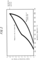
- FIG. 2 illustrates the temperature distribution of the agglomerates inside the furnace when the reduction rate of a product (reduced iron) discharged from the bottom of the shaft furnace is 60 % and when the reduction rate is 20 %.
- the reduction rate of a final product is as low as 20 %, the amount of heat absorbed as the reduction reaction proceeds is relatively small. Therefore, reduced iron of 500 °C or higher is distributed in a region of 1 m to 8 mm from the bottom of the shaft furnace, which indicates that the agglomerates charged into the furnace are kept at 500 °C or higher for a long time.
- the reducing furnace of the operating method for a reducing furnace of the present disclosure is not particularly limited, and a method of using a reducing gas as a reducing agent and blowing the reducing gas into a shaft furnace, a method of using a reducing gas to reduce fine ore in a fluidized bed, a method where agglomeration and reduction of a raw material are integrated (rotary kiln method), and other methods may be used.
- a shaft furnace as the reducing furnace.
- a shaft furnace is a type of vertical furnace, where an agglomerate containing iron oxide, which is a raw material of reduced iron, is charged from the top of the shaft furnace while introducing a reducing gas from the lower part of the furnace, the iron oxide contained in the agglomerate is reduced by the reducing gas to obtain reduced iron, and the reduced iron is discharged from the lower part of the furnace.
- an agglomerate containing iron oxide which is a raw material of reduced iron
- agglomerate is a general term for massive substances containing iron oxide, such as sintered ore, lump ore (massive iron ore), baked pellets, hot briquettes, cold briquettes, and cold bond pellets.
- the present disclosure uses a raw material containing a first agglomerate where a particle is relatively fine and the particle size is within a first particle size range, and a second agglomerate where a particle is relatively coarse and the particle size is within a second particle size range whose lower limit is equal to or more than the upper limit of the first particle size range as a raw material of reduced iron.
- the raw material may contain agglomerates having a particle size outside of the first particle size range and the second particle size range.
- the particle size of the agglomerate is measured according to JIS Z 8815.
- the raw material may contain at least one of the above-mentioned pellet, sintered ore, and lump ore.
- the raw material may contain pellets with a relatively narrow particle size distribution (for example, the width of the particle size distribution is 7 mm), or a combination of multiple pellets with different particle size distributions whose width is relatively narrow.
- pellets having a particle size distribution of 5 mm or more and 12 mm or less can be used as the raw material.
- the raw material contains a first agglomerate having a particle size in a first particle size range of 5 mm or more and 12 mm or less and a second agglomerate having a particle size in a second particle size range of 17 mm or more and 23 mm or less
- a combination of pellets having a particle size distribution of 5 mm or more and 12 mm or less and pellets having a particle size distribution of 17 mm or more and 23 mm or less can be used as the raw material.
- the raw material may contain sintered ore with a relatively wide particle size distribution (for example, the width of the particle size distribution is 100 mm) or lump ore with a relatively wide particle size distribution (for example, the width of the particle size distribution is 20 mm).
- the raw material contains a first agglomerate having a particle size in a first particle size range of 1 mm or more and 10 mm or less and a second agglomerate having a particle size in a second particle size range of 10 mm or more and 100 mm or less
- sintered ore having a particle size distribution of 1 mm or more and 100 mm or less can be used as the raw material.
- the raw material when the raw material contains a first agglomerate having a particle size in a first particle size range of 0.1 mm or more and 10 mm or less and a second agglomerate having a particle size in a second particle size range of 10 mm or more and 100 mm or less, it may, for example, contain a combination of lump ore having a particle size distribution of 0.1 mm or more and 20 mm or less and sintered ore having a particle size distribution of 1 mm or more and 100 mm or less, where the first agglomerate contains first lump ore and sintered ore having a particle size in the first particle size range, and the second agglomerate contains lump ore and sintered ore having a particle size in the second particle size range.
- the first agglomerate preferably has a particle size in a first particle size range selected from a range of 0.1 mm or more and 20 mm or less
- the second agglomerate preferably has a particle size in a second particle size range selected from a range of 1 mm or more and 100 mm or less.
- the first agglomerate has a particle size in a first particle size range of 0.1 mm or more and 20 mm or less
- the second agglomerate has a particle size in a second particle size range of 1 mm or more and 100 mm or less
- the second agglomerate can be used more preferably as a heat supply source in the furnace than otherwise.
- a sieve with a mesh size of 1 mm or more and 20 mm or less for sieving the reduced iron discharged from the reducing furnace.
- a sieve with a mesh size of 1 mm or more and 20 mm or less for sieving the reduced iron, reduced iron with different reduction can be easily separated.
- the second agglomerate with a relatively large particle size is used as a heat supply source for keeping a high temperature inside the furnace, and the iron oxide contained in the first agglomerate with a relatively small particle size is efficiently reduced.
- the raw material is either preheated before being charged into the reducing furnace or heated inside the reducing furnace. This can compensate for the heat absorbed by the reduction reaction of the iron oxide contained in the agglomerate as a raw material.
- the raw material can be preheated by, for example, charging the raw material into a heating furnace maintained at a high temperature, or by keeping the raw material at a high temperature.
- the raw material is preferably preheated to 500 °C or higher.
- the raw material is preferably preheated to 1200 °C or lower. Preheating the raw material to 500 °C or higher can accelerate the reduction reaction.
- the raw material is preheated to 1200 °C or lower, it is possible to prevent the raw material particles from sticking together and from coarsening.
- the raw material is more preferably preheated to 800 °C or higher.
- the raw material is more preferably preheated to 1100 °C or lower.
- the raw material When the raw material is heated inside the reducing furnace, it can be heated with, for example, a method of introducing a hot gas from the top the shaft furnace and exchanging heat with the hot gas, a method of performing heating from the outside of the furnace by electromagnetic waves, or a method of keeping the furnace wall at a high temperature.
- the raw material When the raw material is heated inside the reducing furnace, the raw material is preferably heated to 500 °C or higher.
- the raw material is preferably heated to 1200 °C or lower. Heating the raw material to 500 °C or higher can accelerate the reduction reaction.
- the raw material When the raw material is heated to 1200 °C or lower, it is possible to prevent the raw material particles from sticking together and from coarsening.
- the raw material is more preferably heated to 800 °C or higher.
- the raw material is more preferably heated to 1100 °C or lower.
- a reducing gas that accompanies an endothermic reaction during reduction can be used as the reducing gas.
- the effect of the present disclosure is remarkable if the volume ratio of H 2 gas in the mixed gas is 0.4 or more, as illustrated in FIG. 1 .
- the volume ratio of H 2 gas is 0.8 or more, the effect of the present disclosure is more remarkable because it is difficult to compensate for the heat absorbed by the reaction only by the sensible heat of the gas, that is, only by increasing the amount of the gas.
- the temperature of the reducing gas is preferably 1200 °C or lower.
- the temperature of the reducing gas is 1200 °C or lower, the raw material can be heated while preventing the particles from sticking together.
- the lower limit of the temperature of the reducing gas is not specified, and it may even be room temperature.
- the temperature of the reducing gas is preferably 500 °C or higher.
- the temperature of the reducing gas is more preferably 800 °C or higher.
- the temperature of the reducing gas is more preferably 1100 °C or lower.
- the reduced iron discharged from the reducing furnace is sieved and classified into reduced iron having a particle size range of fine particle and reduced iron having a particle size in a particle size range of coarse particle. This is because the progress of reduction differs depending on the particle size. As used herein, it is preferable to use a sieve with a mesh size of 1 mm or more and 20 mm or less for sieving the reduced iron.
- the reduced iron having a particle size range of fine particle is recovered. This allows only reduced iron with a relatively high reduction rate to be recovered.
- the particle size range of fine particle is preferably 20 mm or less. This allows only reduced iron with a higher reduction rate to be recovered.
- the sieved reduced iron having a particle size in a particle size range of coarse particle. Therefore, it can be used as a raw material in a device different from a reducing furnace in a steelworks, or it can be ground and then reduced again as an agglomerate of raw material, for example. In this case, the agglomerate as a raw material can be reduced more efficiently.
- the ground reduced iron can be used in the same way as an agglomerate of new raw material.
- the weight ratio of the used ground reduced iron to reduced iron as a product is preferably 0.2 or more. The weight ratio is preferably 0.5 or less.
- FIG. 3 illustrates a suitable example of the operating method for a reducing furnace of the present disclosure.
- a preheated agglomerate which is a new raw material, is introduced from the top of a shaft furnace (first shaft furnace) while introducing H 2 gas as a reducing gas from the lower part of the side of the shaft furnace, and the iron oxide contained in the agglomerate is reduced by the H 2 gas.
- the resulting reduced iron is discharged from the lower part of the first shaft furnace, and it is sieved and classified into reduced iron having a particle size range of fine particle and reduced iron having a particle size in a particle size range of coarse particle.
- the reduced iron having a particle size range of fine particle is recovered.
- the reduced iron having a particle size range of coarse particle is ground and then charged into a shaft furnace (second shaft furnace) different from the first shaft furnace, and the H 2 gas not used in the reduction reaction and the formed H 2 O gas discharged from the first shaft furnace are introduced as a reducing gas to reduce the iron oxide contained in the ground reduced iron having a particle size range of coarse particle.
- the H 2 gas not used in the reduction reaction and the formed H 2 O gas discharged from the first shaft furnace are hot, so that the ground reduced iron having a particle size range of coarse particle can be heated through heat exchange.
- the reduced iron having a particle size range of coarse particle discharged from the lower part of the second shaft furnace is ground, heated, and then charged into the first shaft furnace together with a new raw material.
- the H 2 not used in the reduction reaction and the formed H 2 O gas discharged from the second shaft furnace are dehumidified and then introduced into the first shaft furnace as a reducing gas together with fresh H 2 gas.
- the ground reduced iron having a particle size range of coarse particle is reduced in the second shaft furnace. It is also acceptable to heat the ground reduced iron having a particle size range of coarse particle and charge it into the first shaft furnace.
- the H 2 gas not used in the reduction reaction and the formed H 2 O gas discharged from the first shaft furnace may be used to heat the ground reduced iron having a particle size range of coarse particle.
- the preheated raw material is charged into the first shaft furnace, and the reduced iron having a particle size in a particle size range of coarse particle that is discharged from the first shaft furnace and obtained by sieving is ground, heated, and then charged into the first shaft furnace.
- the present disclosure is not limited to this example.
- a gas inlet for introducing hot gases such as H 2 , H 2 O, and oxygen (O 2 ) and a gas outlet for exhausting the introduced hot gases are provided at the upper part of the side of the first shaft furnace, and a raw material that has not been preheated and the ground reduced iron having a particle size in a particle size range of coarse particle are charged into the first shaft furnace and then heated.
- the hot gas may be obtained by partial combustion outside the furnace, or by introducing H 2 O and/or O 2 into the furnace and partially burning the reducing gas rising from below.
- the amount of O 2 in the gas composition inside the furnace so that H 2 O/(H 2 O+H 2 ) is 0.5 or more, the reduction from FeO to Fe can be suppressed. As a result, it is possible to suppress the endothermic reaction and preheat the raw material with a small amount of gas, which is preferable.
- an agglomerate A coarse particle
- an agglomerate B fine particle
- the "agglomerate” is a massive substance containing iron oxide, and sintered ore, lump ore (massive iron ore), baked pellets, hot briquettes, cold briquettes, and cold bond pellets may be suitably used, for example.
- sintered ore was used as a raw material for a blast furnace, the sintered ore was sieved using a 30-mm sieve, the undersize sintered ore was sieved again using a 20-mm sieve, and the oversize sintered ore was used as the agglomerate A (coarse particle). Further, the sintered ore undersize of 20 mm was sieved using a 10-mm sieve, the sintered ore undersize of 10 mm was sieved again using a 5-mm sieve, and the oversize sintered ore was used as the agglomerate B (fine particle).
- a reduction experiment was conducted using only the agglomerate B (fine particle) prepared as described above.
- the agglomerates were filled into a container having a predetermined volume to previously measure the so-called bulk density.
- the agglomerates were filled in small quantities so that particle size segregation would not occur, and the agglomerates were heated by an electric furnace to 1000 °C in a nitrogen atmosphere and held for a certain period of time. It was confirmed that the temperature of the agglomerates charged into the furnace was raised to approximately 1000 °C.
- H 2 gas was supplied as a reducing gas from the lower part of the furnace to start the reduction of the iron oxide contained in the agglomerates.
- a lifting device was lowered to lower the surface of the agglomerate at a (constant) descent speed at which the agglomerate is discharged 1.6 kg per hour in a pre-reduction state by a level sensor at the top.
- the supplied H 2 gas was 1200 NL per hour (volume under standard conditions (temperature 0 °C, atmospheric pressure 1013 hPa, relative humidity 0 %) at room temperature (25 °C).
- the gas introduced into the device was switched from a reducing gas to nitrogen gas, the agglomerate was cooled, and then the lifting device was lowered to remove a sample of the agglomerate from the lower part of the furnace.
- the average reduction rate of a product from the sample of the agglomerate was determined, and the result was 36 %.
- the reduction conditions, the reduction rate of the product, and the mass ratio of undersize are listed in Table 1.
- the iron oxide contained in an agglomerate was reduced in the same manner as in Comparative Example.
- an agglomerate obtained by mixing the agglomerate A (coarse particle) and the agglomerate B (fine particle) at a mass ratio of 1:1 was used as a raw material. All other conditions were the same as in Comparative Example.
- the average reduction rate of the product was 35 %.
- the reduction rate of the fine particles, which were below the sieve was as high as 46 %, whereas the reduction rate of the coarse particles, which were above the sieve, was as low as 24 %.
- the reduction conditions, the reduction rate of the product, and the mass ratio of undersize are listed in Table 1.
- the reducing gas was H 2 gas, which tended to cause the reduction reaction to proceed relatively uniformly to the interior of the particles of the agglomerate.
- the reaction time was limited, there was a difference in the reduction rate between the particle surface and the center. In other words, it was found that the reduction was more likely to proceed on the surface of the particles, and the reduction was less likely to proceed in the center of the particles.
- the temperature distribution of the agglomerate layer was measured from the top of the furnace in the furnace height direction during the reduction experiment.
- the temperature in the furnace was measured under the conditions of Comparative Example, that is, in the case of the agglomerate B (fine particle)
- the temperature dropped sharply at a certain height.
- the temperature in the furnace was measured under the conditions of Example 1, that is, in the case of using a mixture of the agglomerate A (coarse particle) and the agglomerate B (fine particle)
- the temperature gradually decreased at approximately the same height as above, and the range in which the temperature was kept high was expanded as with the calculation results illustrated in FIG. 2 .
- Example 1 The reduced iron obtained in Example 1 was sieved to recover coarse particles (20 mm to 30 mm). The coarse particles after reduction were ground to a particle size of less than 10 mm to obtain an agglomerate C (fine particle). The agglomerate A (coarse particle), the agglomerate B (fine particle), and the agglomerate C (fine particle) were mixed at a ratio of 1:1:1. The mixed agglomerates were used as a raw material to reduce the iron oxide contained in the agglomerates in the same manner as in Example 1. All the conditions were the same as in Example 1.
Landscapes
- Engineering & Computer Science (AREA)
- Chemical & Material Sciences (AREA)
- Metallurgy (AREA)
- Manufacturing & Machinery (AREA)
- Materials Engineering (AREA)
- Organic Chemistry (AREA)
- Geochemistry & Mineralogy (AREA)
- Geology (AREA)
- General Life Sciences & Earth Sciences (AREA)
- Environmental & Geological Engineering (AREA)
- Life Sciences & Earth Sciences (AREA)
- Mechanical Engineering (AREA)
- Manufacture And Refinement Of Metals (AREA)
- Manufacture Of Iron (AREA)
- Gasification And Melting Of Waste (AREA)
Abstract
Description
- This disclosure relates to an operating method for a reducing furnace.
- Known methods of producing iron by reducing a raw material containing iron oxide include a blast furnace method where coke is used as a reducing agent to produce hot metal, a method where a reducing gas is used as a reducing agent and is blown into a vertical furnace (hereinafter referred to as "shaft furnace"), a method that also uses a reducing gas where the reducing gas reduces fine ore in a fluidized bed, a method where agglomeration and reduction of a raw material are integrated (rotary kiln method), and other methods.
- These reduced iron production methods, except for the blast furnace method, use a reducing gas mainly composed of carbon monoxide (CO) or hydrogen (H2) produced by reforming natural gas or coal as a reducing agent. Raw materials charged into a furnace are heated by convective heat transfer with the reducing gas, reduced, and then discharged out of the furnace. Oxidized gases such as water (H2O) and carbon dioxide (CO2), as well as H2 gas and CO gas that do not contribute to the reduction reaction, are discharged out of the furnace.
- The raw materials (mainly Fe2O3) charged into the furnace undergo reduction reactions represented by the following equations (1) and (2) with CO gas and H2 gas, which are reducing gases.
Fe2O3 + 3CO → 2Fe + 3CO2 (1)
Fe2O3 + 3H2 → 2Fe + 3H2O (2)
- That is, in the reduction by CO gas represented by the equation (1), CO2 gas is discharged as emission gas after the reduction. On the other hand, in the reduction by H2 gas represented by the equation (2), H2O gas is discharged as emission gas after the reduction.
-
FIG. 1 illustrates the relationship between the volume fraction x of H2 in a reducing gas and the reaction heat ΔrH in a reduction reaction of iron oxide by a reducing gas containing CO gas and H2 gas. InFIG. 1 , a negative reaction heat ΔrH indicates an exothermic reaction, and a positive value indicates an endothermic reaction. As is clear fromFIG. 1 , when the volume fraction x of H2 is 0.4 or more, the reduction reaction is an endothermic reaction. - In recent years, because of the problem of global warming, it is necessary to decrease the amount of the reduction reaction by CO gas represented by the equation (1) and increase the amount of the reduction reaction by H2 gas represented by the equation (2) to control emissions of CO2, which is one of the greenhouse gases that cause global warming. To increase the amount of the reduction reaction by H2 gas, the concentration of H2 in the reducing gas used should be increased.
- However, the reduction reactions by CO gas and H2 gas differ in the amount of heat associated with each reaction. That is, the amount of heat of the reduction reaction by CO gas is +6710 kcal/kmol (Fe2O3), whereas the amount of the heat of the reduction reaction by H2 gas is -22800 kcal/kmol (Fe2O3). In other words, the former is an exothermic reaction, whereas the latter is an endothermic reaction. Therefore, when the H2 concentration in the reducing gas is increased to increase the amount of the reaction of the equation (2), a notable endothermic reaction occurs to lower the temperature inside the furnace, and the reduction reaction is stagnated. Therefore, it is necessary to compensate for the lack of heat by some means.
- A possible way to compensate for the lack of heat is to supply heat by raising the temperature of the reducing gas to a high temperature and increasing the amount of the gas. However, compared to the conventional case of reforming natural gas into CO and H2, for example, the case of using only H2 at the same temperature requires about 1.5 times the amount of gas because of the heat balance. An increase in the amount of gas used requires gas heating and reforming devices to form hot gas and increases the treatment in gas treating devices to remove CO2 gas and H2O after the reaction, which significantly increases device costs.
- Therefore,
JP 2012-102371 A - PTL 1:
JP 2012-102371 A - The method of preheating a raw material described in
PTL 1 is an excellent method in that heat is supplied not only from a hot reducing gas but also from an agglomerate as a raw material, which can reduce the amount of reducing gas used. However, the amount of heat absorbed by the reduction reaction between iron oxide contained in the raw material and H2 is more than the sensible heat possessed by the hot raw material that has been preheated. Therefore, the effect of simply preheating a raw material is limited, and it is desired to develop a method with which iron oxide contained in a raw material can be reduced more efficiently. - It could thus be helpful to provide an operating method for a reducing furnace with which iron oxide contained in a raw material can be reduced more efficiently than conventional methods.
- We thus provide the following.
- [1] An operating method for a reducing furnace, comprising charging a raw material containing iron oxide into a reducing furnace while introducing a reducing gas that accompanies an endothermic reaction during reduction into the reducing furnace, and reducing the iron oxide to obtain reduced iron, wherein
- the raw material contains a first agglomerate with a particle size in a first particle size range and a second agglomerate with a particle size in a second particle size range whose lower limit is equal to or more than an upper limit of the first particle size range, and the raw material is preheated before being charged into the reducing furnace or heated inside the reducing furnace, and
- the reduced iron discharged from the reducing furnace is sieved and classified into reduced iron having a particle size range of fine particle and reduced iron having a particle size in a particle size range of coarse particle, and the reduced iron having a particle size range of fine particle is recovered.
- [2] The operating method for a reducing furnace according to aspect [1], wherein after grinding the reduced iron having a particle size of coarse particle, the ground reduced iron is preheated and then charged into the reducing furnace, or the ground reduced iron is charged into the reducing furnace and heated.
- [3] The operating method for a reducing furnace according to aspect [1] or [2], wherein the first agglomerate has a particle size in the first particle size range selected from a range of 0.1 mm or more and 20 mm or less, the second agglomerate has a particle size in the second particle size range selected from a range of 1 mm or more and 100 mm or less, and a sieve with a mesh size of 1 mm or more and 20 mm or less is used to sieve the reduced iron discharged from the reducing furnace.
- [4] The operating method for a reducing furnace according to any one of aspects [1] to [3], wherein the particle size range of fine particle is 20 mm or less.
- [5] The operating method for a reducing furnace according to any one of aspects [1] to [4], wherein the raw material is preheated to 500 °C or higher and 1200 °C or lower before being charged into the reducing furnace, or the raw material is heated to 500 °C or higher and 1200 °C or lower inside the reducing furnace.
- According to the present disclosure, it is possible to provide an operating method for a reducing furnace with which iron oxide contained in a raw material can be reduced more efficiently than conventional methods.
- In the accompanying drawings:
-
FIG. 1 illustrates the relationship between the volume fraction of H2 in a reducing gas and the reaction heat in a reduction reaction of iron oxide by a reducing gas containing CO gas and H2 gas; -
FIG. 2 illustrates the temperature distribution of agglomerates inside a shaft furnace when the reduction rate of a product (reduced iron) discharged from the bottom of the shaft furnace is 60 % and when the reduction rate is 20 %; -
FIG. 3 illustrates a suitable example of the operating method for a reducing furnace of the present disclosure; -
FIG. 4 illustrates a key part of another suitable example of the operating method for a reducing furnace of the present disclosure; and -
FIG. 5 illustrates an experimental device used in Examples. - The following describes embodiments of the present disclosure with reference to the drawings. The operating method for a reducing furnace of the present disclosure includes charging a raw material containing iron oxide into a reducing furnace while introducing a reducing gas that accompanies an endothermic reaction during reduction into the reducing furnace, and reducing the iron oxide to obtain reduced iron, where the raw material contains a first agglomerate with a particle size in a first particle size range and a second agglomerate with a particle size in a second particle size range whose lower limit is equal to or more than an upper limit of the first particle size range, the raw material is preheated before being charged into the reducing furnace or heated inside the reducing furnace, the reduced iron discharged from the reducing furnace is sieved and classified into reduced iron having a particle size range of fine particle and reduced iron having a particle size in a particle size range of coarse particle, and the reduced iron having a particle size range of fine particle is recovered.
- We have extensively studied ways to reduce iron oxide contained in a raw material more efficiently than conventional methods. As a result, we discovered that it is extremely effective to use a raw material containing a first agglomerate where a particle is relatively fine and the particle size is within a first particle size range, and a second agglomerate where a particle is relatively coarse and the particle size is within a second particle size range whose lower limit is equal to or more than the upper limit of the first particle size range. The following describes experiments that led to this discovery.
- We performed a one-dimensional heat transfer calculation in the height direction to simulate the reduction reaction of an agglomerate in a shaft furnace. The calculation was performed on the assumption that an 8-meter-high shaft furnace was used, and agglomerates that had been preheated to 1000 °C were charged as raw materials from the top of the furnace at a rate of 1.6 tonnes per hour while supplying 800 Nm3/h of H2 gas from the bottom of the furnace at 25 °C to reduced iron oxide contained in the agglomerates. Further, it was assumed that the reduction reaction occurred at temperatures of 500 °C or higher and proceeded at a constant rate.
-
FIG. 2 illustrates the temperature distribution of the agglomerates inside the furnace when the reduction rate of a product (reduced iron) discharged from the bottom of the shaft furnace is 60 % and when the reduction rate is 20 %. As is clear fromFIG. 2 , when the reduction rate of a final product is as low as 20 %, the amount of heat absorbed as the reduction reaction proceeds is relatively small. Therefore, reduced iron of 500 °C or higher is distributed in a region of 1 m to 8 mm from the bottom of the shaft furnace, which indicates that the agglomerates charged into the furnace are kept at 500 °C or higher for a long time. - On the other hand, when the reduction rate of a product is 60 %, the amount of heat absorbed as the reduction reaction proceeds is relatively large. Therefore, reduced iron of 500 °C or higher is distributed in a region of 4 m to 8 mm from the bottom of the shaft furnace, which indicates that the agglomerates charged into the furnace are kept at 500 °C or higher for a short time.
- Based on the above results, we thought that an agglomerate for which a reduction reaction proceeds slowly, such as an agglomerate with a relatively coarse particle size, could be utilized as a heat supply source to keep a high temperature inside the furnace. Further, we discovered that when a raw material containing an agglomerate with a relatively large particle size that is utilized as a heat supply source and an agglomerate with a high reduction rate and a relatively small particle size for which a reduction reaction proceeds quickly is used, reduced iron discharged from a reducing furnace is sieved and classified into reduced iron having a particle size range of fine particle and reduced iron having a particle size in a particle size range of coarse particle, and the reduced iron having a particle size range of fine particle is recovered, it is possible to recover reduced iron with a high reduction rate and to reduce the iron oxide contained in a raw material efficiently, thereby completing the present disclosure. The following describes each part of the operating method for a reducing furnace of the present disclosure.
- First, the reducing furnace of the operating method for a reducing furnace of the present disclosure is not particularly limited, and a method of using a reducing gas as a reducing agent and blowing the reducing gas into a shaft furnace, a method of using a reducing gas to reduce fine ore in a fluidized bed, a method where agglomeration and reduction of a raw material are integrated (rotary kiln method), and other methods may be used. Among these methods, it is preferable to use a shaft furnace as the reducing furnace. A shaft furnace is a type of vertical furnace, where an agglomerate containing iron oxide, which is a raw material of reduced iron, is charged from the top of the shaft furnace while introducing a reducing gas from the lower part of the furnace, the iron oxide contained in the agglomerate is reduced by the reducing gas to obtain reduced iron, and the reduced iron is discharged from the lower part of the furnace.
- In the present specification, "agglomerate" is a general term for massive substances containing iron oxide, such as sintered ore, lump ore (massive iron ore), baked pellets, hot briquettes, cold briquettes, and cold bond pellets. The present disclosure uses a raw material containing a first agglomerate where a particle is relatively fine and the particle size is within a first particle size range, and a second agglomerate where a particle is relatively coarse and the particle size is within a second particle size range whose lower limit is equal to or more than the upper limit of the first particle size range as a raw material of reduced iron. The raw material may contain agglomerates having a particle size outside of the first particle size range and the second particle size range. The particle size of the agglomerate is measured according to JIS Z 8815.
- The raw material may contain at least one of the above-mentioned pellet, sintered ore, and lump ore. Specifically, the raw material may contain pellets with a relatively narrow particle size distribution (for example, the width of the particle size distribution is 7 mm), or a combination of multiple pellets with different particle size distributions whose width is relatively narrow. For example, when the raw material contains a first agglomerate having a particle size in a first particle size range of 5 mm or more and 7 mm or less and a second agglomerate having a particle size in a second particle size range of 10 mm or more and 12 mm or less, pellets having a particle size distribution of 5 mm or more and 12 mm or less can be used as the raw material. Further, when the raw material contains a first agglomerate having a particle size in a first particle size range of 5 mm or more and 12 mm or less and a second agglomerate having a particle size in a second particle size range of 17 mm or more and 23 mm or less, a combination of pellets having a particle size distribution of 5 mm or more and 12 mm or less and pellets having a particle size distribution of 17 mm or more and 23 mm or less can be used as the raw material.
- The raw material may contain sintered ore with a relatively wide particle size distribution (for example, the width of the particle size distribution is 100 mm) or lump ore with a relatively wide particle size distribution (for example, the width of the particle size distribution is 20 mm). For example, when the raw material contains a first agglomerate having a particle size in a first particle size range of 1 mm or more and 10 mm or less and a second agglomerate having a particle size in a second particle size range of 10 mm or more and 100 mm or less, sintered ore having a particle size distribution of 1 mm or more and 100 mm or less can be used as the raw material.
- Further, when the raw material contains a first agglomerate having a particle size in a first particle size range of 0.1 mm or more and 10 mm or less and a second agglomerate having a particle size in a second particle size range of 10 mm or more and 100 mm or less, it may, for example, contain a combination of lump ore having a particle size distribution of 0.1 mm or more and 20 mm or less and sintered ore having a particle size distribution of 1 mm or more and 100 mm or less, where the first agglomerate contains first lump ore and sintered ore having a particle size in the first particle size range, and the second agglomerate contains lump ore and sintered ore having a particle size in the second particle size range.
- The first agglomerate preferably has a particle size in a first particle size range selected from a range of 0.1 mm or more and 20 mm or less, and the second agglomerate preferably has a particle size in a second particle size range selected from a range of 1 mm or more and 100 mm or less. When the first agglomerate has a particle size in a first particle size range of 0.1 mm or more and 20 mm or less, it is possible to obtain reduced iron with a higher reduction rate than otherwise. Further, when the second agglomerate has a particle size in a second particle size range of 1 mm or more and 100 mm or less, the second agglomerate can be used more preferably as a heat supply source in the furnace than otherwise.
- It is preferable to use a sieve with a mesh size of 1 mm or more and 20 mm or less for sieving the reduced iron discharged from the reducing furnace. By using a sieve with a mesh size of 1 mm or more and 20 mm or less for sieving the reduced iron, reduced iron with different reduction can be easily separated.
- In the present disclosure, among the plurality of particle size ranges described above, the second agglomerate with a relatively large particle size is used as a heat supply source for keeping a high temperature inside the furnace, and the iron oxide contained in the first agglomerate with a relatively small particle size is efficiently reduced.
- The raw material is either preheated before being charged into the reducing furnace or heated inside the reducing furnace. This can compensate for the heat absorbed by the reduction reaction of the iron oxide contained in the agglomerate as a raw material.
- When the raw material is preheated before being charged into the reducing furnace, the raw material can be preheated by, for example, charging the raw material into a heating furnace maintained at a high temperature, or by keeping the raw material at a high temperature. When the raw material is preheated, the raw material is preferably preheated to 500 °C or higher. The raw material is preferably preheated to 1200 °C or lower. Preheating the raw material to 500 °C or higher can accelerate the reduction reaction. When the raw material is preheated to 1200 °C or lower, it is possible to prevent the raw material particles from sticking together and from coarsening. The raw material is more preferably preheated to 800 °C or higher. The raw material is more preferably preheated to 1100 °C or lower.
- When the raw material is heated inside the reducing furnace, it can be heated with, for example, a method of introducing a hot gas from the top the shaft furnace and exchanging heat with the hot gas, a method of performing heating from the outside of the furnace by electromagnetic waves, or a method of keeping the furnace wall at a high temperature. When the raw material is heated inside the reducing furnace, the raw material is preferably heated to 500 °C or higher. The raw material is preferably heated to 1200 °C or lower. Heating the raw material to 500 °C or higher can accelerate the reduction reaction. When the raw material is heated to 1200 °C or lower, it is possible to prevent the raw material particles from sticking together and from coarsening. The raw material is more preferably heated to 800 °C or higher. The raw material is more preferably heated to 1100 °C or lower.
- On the other hand, a reducing gas that accompanies an endothermic reaction during reduction can be used as the reducing gas. For example, in a case of using a mixed gas of CO gas and H2 gas as the reducing gas and setting the reduction reaction temperature inside the reducing furnace to 1200 °C or lower, the effect of the present disclosure is remarkable if the volume ratio of H2 gas in the mixed gas is 0.4 or more, as illustrated in
FIG. 1 . Further, when the volume ratio of H2 gas is 0.8 or more, the effect of the present disclosure is more remarkable because it is difficult to compensate for the heat absorbed by the reaction only by the sensible heat of the gas, that is, only by increasing the amount of the gas. - The temperature of the reducing gas is preferably 1200 °C or lower. When the temperature of the reducing gas is 1200 °C or lower, the raw material can be heated while preventing the particles from sticking together. When the raw material is preheated or when a method of performing heating from the outside of the furnace by electromagnetic waves, a method of keeping the furnace wall at a high temperature, or the like is used, the lower limit of the temperature of the reducing gas is not specified, and it may even be room temperature. However, when the reducing gas is used to heat the raw material, the temperature of the reducing gas is preferably 500 °C or higher. The temperature of the reducing gas is more preferably 800 °C or higher. The temperature of the reducing gas is more preferably 1100 °C or lower.
- The reduced iron discharged from the reducing furnace is sieved and classified into reduced iron having a particle size range of fine particle and reduced iron having a particle size in a particle size range of coarse particle. This is because the progress of reduction differs depending on the particle size. As used herein, it is preferable to use a sieve with a mesh size of 1 mm or more and 20 mm or less for sieving the reduced iron. The reduced iron having a particle size range of fine particle is recovered. This allows only reduced iron with a relatively high reduction rate to be recovered.
- The particle size range of fine particle is preferably 20 mm or less. This allows only reduced iron with a higher reduction rate to be recovered.
- On the other hand, there is a high possibility that many unreduced parts remain inside the sieved reduced iron having a particle size in a particle size range of coarse particle. Therefore, it can be used as a raw material in a device different from a reducing furnace in a steelworks, or it can be ground and then reduced again as an agglomerate of raw material, for example. In this case, the agglomerate as a raw material can be reduced more efficiently. The ground reduced iron can be used in the same way as an agglomerate of new raw material. To reduce the amount of the gas in the reducing furnace, the weight ratio of the used ground reduced iron to reduced iron as a product is preferably 0.2 or more. The weight ratio is preferably 0.5 or less.
-
FIG. 3 illustrates a suitable example of the operating method for a reducing furnace of the present disclosure. First, a preheated agglomerate, which is a new raw material, is introduced from the top of a shaft furnace (first shaft furnace) while introducing H2 gas as a reducing gas from the lower part of the side of the shaft furnace, and the iron oxide contained in the agglomerate is reduced by the H2 gas. - The resulting reduced iron is discharged from the lower part of the first shaft furnace, and it is sieved and classified into reduced iron having a particle size range of fine particle and reduced iron having a particle size in a particle size range of coarse particle. The reduced iron having a particle size range of fine particle is recovered. On the other hand, the reduced iron having a particle size range of coarse particle is ground and then charged into a shaft furnace (second shaft furnace) different from the first shaft furnace, and the H2 gas not used in the reduction reaction and the formed H2O gas discharged from the first shaft furnace are introduced as a reducing gas to reduce the iron oxide contained in the ground reduced iron having a particle size range of coarse particle.
- The H2 gas not used in the reduction reaction and the formed H2O gas discharged from the first shaft furnace are hot, so that the ground reduced iron having a particle size range of coarse particle can be heated through heat exchange. The reduced iron having a particle size range of coarse particle discharged from the lower part of the second shaft furnace is ground, heated, and then charged into the first shaft furnace together with a new raw material. On the other hand, the H2 not used in the reduction reaction and the formed H2O gas discharged from the second shaft furnace are dehumidified and then introduced into the first shaft furnace as a reducing gas together with fresh H2 gas.
- In the example illustrated in
FIG. 3 , the ground reduced iron having a particle size range of coarse particle is reduced in the second shaft furnace. It is also acceptable to heat the ground reduced iron having a particle size range of coarse particle and charge it into the first shaft furnace. In this case, the H2 gas not used in the reduction reaction and the formed H2O gas discharged from the first shaft furnace may be used to heat the ground reduced iron having a particle size range of coarse particle. - In the example illustrated in
FIG. 3 , the preheated raw material is charged into the first shaft furnace, and the reduced iron having a particle size in a particle size range of coarse particle that is discharged from the first shaft furnace and obtained by sieving is ground, heated, and then charged into the first shaft furnace. However, the present disclosure is not limited to this example. For example, it is also acceptable that, as illustrated inFIG. 4 , a gas inlet for introducing hot gases such as H2, H2O, and oxygen (O2) and a gas outlet for exhausting the introduced hot gases are provided at the upper part of the side of the first shaft furnace, and a raw material that has not been preheated and the ground reduced iron having a particle size in a particle size range of coarse particle are charged into the first shaft furnace and then heated. The hot gas may be obtained by partial combustion outside the furnace, or by introducing H2O and/or O2 into the furnace and partially burning the reducing gas rising from below. By adjusting the amount of O2 in the gas composition inside the furnace so that H2O/(H2O+H2) is 0.5 or more, the reduction from FeO to Fe can be suppressed. As a result, it is possible to suppress the endothermic reaction and preheat the raw material with a small amount of gas, which is preferable. - The following describes examples of the present disclosure, but the present disclosure is not limited to the following examples.
- To confirm the effect of the particle size of an agglomerate, an agglomerate A (coarse particle) and an agglomerate B (fine particle) were prepared by adjusting the particle size of the agglomerates, and a reduction experiment was conducted. The "agglomerate" is a massive substance containing iron oxide, and sintered ore, lump ore (massive iron ore), baked pellets, hot briquettes, cold briquettes, and cold bond pellets may be suitably used, for example. In this case, sintered ore was used as a raw material for a blast furnace, the sintered ore was sieved using a 30-mm sieve, the undersize sintered ore was sieved again using a 20-mm sieve, and the oversize sintered ore was used as the agglomerate A (coarse particle). Further, the sintered ore undersize of 20 mm was sieved using a 10-mm sieve, the sintered ore undersize of 10 mm was sieved again using a 5-mm sieve, and the oversize sintered ore was used as the agglomerate B (fine particle).
- A reduction experiment was conducted using only the agglomerate B (fine particle) prepared as described above. The agglomerates were filled into a container having a predetermined volume to previously measure the so-called bulk density. Next, using the experimental device illustrated in
FIG. 5 , the agglomerates were filled in small quantities so that particle size segregation would not occur, and the agglomerates were heated by an electric furnace to 1000 °C in a nitrogen atmosphere and held for a certain period of time. It was confirmed that the temperature of the agglomerates charged into the furnace was raised to approximately 1000 °C. - After that, heating by the electric furnace was stopped, and H2 gas was supplied as a reducing gas from the lower part of the furnace to start the reduction of the iron oxide contained in the agglomerates. A lifting device was lowered to lower the surface of the agglomerate at a (constant) descent speed at which the agglomerate is discharged 1.6 kg per hour in a pre-reduction state by a level sensor at the top. The supplied H2 gas was 1200 NL per hour (volume under standard conditions (
temperature 0 °C, atmospheric pressure 1013 hPa,relative humidity 0 %) at room temperature (25 °C). - When the top of the agglomerate reached the bottom of the electric furnace, the gas introduced into the device was switched from a reducing gas to nitrogen gas, the agglomerate was cooled, and then the lifting device was lowered to remove a sample of the agglomerate from the lower part of the furnace. The average reduction rate of a product from the sample of the agglomerate was determined, and the result was 36 %. The reduction conditions, the reduction rate of the product, and the mass ratio of undersize are listed in Table 1.
-
Table 1 Raw material Reducing furnace Product Agglomerate A (coarse particle) : agglomerate B (fine particle) : agglomerate C (fine particle) (mass ratio) Average reduction rate (%) Temperature at start of reduction (°C) Raw material supply speed (kg/h) Reducing gas supply (NL/h) Average reduction rate (%) Reduction rate of fine particle (-10mm) (%) Reduction rate of coarse particle (+10mm) (%) Mass ratio of undersize (mass%) Comparative Example 0:1:0 0 1000 1.6 H 2 120036 36 - 100 Example 1 1:1:0 0 1000 1.6 H 2 120035 46 24 48 Example 2 1:1:1 8 1000 1.6 H 2 120045 54 27 64 - The iron oxide contained in an agglomerate was reduced in the same manner as in Comparative Example. However, an agglomerate obtained by mixing the agglomerate A (coarse particle) and the agglomerate B (fine particle) at a mass ratio of 1:1 was used as a raw material. All other conditions were the same as in Comparative Example. As a result, the average reduction rate of the product was 35 %. When the particles were sieved using a 10-mm sieve, the reduction rate of the fine particles, which were below the sieve, was as high as 46 %, whereas the reduction rate of the coarse particles, which were above the sieve, was as low as 24 %. The reduction conditions, the reduction rate of the product, and the mass ratio of undersize are listed in Table 1.
- The reducing gas was H2 gas, which tended to cause the reduction reaction to proceed relatively uniformly to the interior of the particles of the agglomerate. However, since the reaction time was limited, there was a difference in the reduction rate between the particle surface and the center. In other words, it was found that the reduction was more likely to proceed on the surface of the particles, and the reduction was less likely to proceed in the center of the particles.
- The temperature distribution of the agglomerate layer was measured from the top of the furnace in the furnace height direction during the reduction experiment. When the temperature in the furnace was measured under the conditions of Comparative Example, that is, in the case of the agglomerate B (fine particle), the temperature dropped sharply at a certain height. On the other hand, when the temperature in the furnace was measured under the conditions of Example 1, that is, in the case of using a mixture of the agglomerate A (coarse particle) and the agglomerate B (fine particle), the temperature gradually decreased at approximately the same height as above, and the range in which the temperature was kept high was expanded as with the calculation results illustrated in
FIG. 2 . - Base on this, it was estimated that the position at which the reduction reaction proceeded was different between the agglomerate A (coarse particle) and the agglomerate B (fine particle) in the height direction. Thus, in the case of using a reducing gas that accompanies an endothermic reaction during the reduction, by using a raw material having an agglomerate with a relatively small particle size and an agglomerate with a relatively large particle size, it is possible to cause the reduction reaction at different positions in the shaft furnace and to moderate the temperature drop accompanying the reduction reaction. As a result, the temperature at which the reduction reaction occurs is kept for a longer period of time inside the shaft furnace, which facilitates the proceeding of the reduction. It was found that the reduction proceeds slowly for the agglomerate A (coarse particle), which can suppress the heat absorption associated with the reaction, and the agglomerate A (coarse particle) can play a role as a heat supply medium.
- The reduced iron obtained in Example 1 was sieved to recover coarse particles (20 mm to 30 mm). The coarse particles after reduction were ground to a particle size of less than 10 mm to obtain an agglomerate C (fine particle). The agglomerate A (coarse particle), the agglomerate B (fine particle), and the agglomerate C (fine particle) were mixed at a ratio of 1:1:1. The mixed agglomerates were used as a raw material to reduce the iron oxide contained in the agglomerates in the same manner as in Example 1. All the conditions were the same as in Example 1. The results were that the average reduction rate of the product was 45 %, the reduction rate of the coarse particle (+10 mm) was 27 %, and the reduction rate of the fine particle (-10 mm) was 54 %. When the obtained reduced iron was sieved using a 10-mm sieve, 64 % of the undersize product could be recovered. The reduction conditions, the reduction rate of the product, and the mass ratio of undersize are listed in Table 1.
- Thus, by sieving the obtained reduced iron, it is possible to easily separate the portions with a high reduction rate and to increase the reduction rate of the undersize product that can be used as reduced iron.
- According to the present disclosure, it is possible to provide an operating method for a reducing furnace with which iron oxide contained in a raw material can be reduced more efficiently than conventional methods, which is useful in the steel industry.
Claims (5)
- An operating method for a reducing furnace, comprising charging a raw material containing iron oxide into a reducing furnace while introducing a reducing gas that accompanies an endothermic reaction during reduction into the reducing furnace, and reducing the iron oxide to obtain reduced iron, whereinthe raw material contains a first agglomerate with a particle size in a first particle size range and a second agglomerate with a particle size in a second particle size range whose lower limit is equal to or more than an upper limit of the first particle size range, and the raw material is preheated before being charged into the reducing furnace or heated inside the reducing furnace, andthe reduced iron discharged from the reducing furnace is sieved and classified into reduced iron having a particle size range of fine particle and reduced iron having a particle size in a particle size range of coarse particle, and the reduced iron having a particle size range of fine particle is recovered.
- The operating method for a reducing furnace according to claim 1, wherein after grinding the reduced iron having a particle size of coarse particle, the ground reduced iron is preheated and then charged into the reducing furnace, or the ground reduced iron is charged into the reducing furnace and heated.
- The operating method for a reducing furnace according to claim 1 or 2, wherein the first agglomerate has a particle size in the first particle size range selected from a range of 0.1 mm or more and 20 mm or less, the second agglomerate has a particle size in the second particle size range selected from a range of 1 mm or more and 100 mm or less, and a sieve with a mesh size of 1 mm or more and 20 mm or less is used to sieve the reduced iron discharged from the reducing furnace.
- The operating method for a reducing furnace according to any one of claims 1 to 3, wherein the particle size range of fine particle is 0.1 mm or more and 20 mm or less.
- The operating method for a reducing furnace according to any one of claims 1 to 4, wherein the raw material is preheated to 500 °C or higher and 1200 °C or lower before being charged into the reducing furnace, or the raw material is heated to 500 °C or higher and 1200 °C or lower inside the reducing furnace.
Applications Claiming Priority (2)
| Application Number | Priority Date | Filing Date | Title |
|---|---|---|---|
| JP2021062160A JP7040659B1 (en) | 2021-03-31 | 2021-03-31 | How to operate the reduction furnace |
| PCT/JP2021/044585 WO2022209015A1 (en) | 2021-03-31 | 2021-12-03 | Operating method for reducing furnace |
Publications (2)
| Publication Number | Publication Date |
|---|---|
| EP4317465A1 true EP4317465A1 (en) | 2024-02-07 |
| EP4317465A4 EP4317465A4 (en) | 2025-05-28 |
Family
ID=81214340
Family Applications (1)
| Application Number | Title | Priority Date | Filing Date |
|---|---|---|---|
| EP21935168.1A Pending EP4317465A4 (en) | 2021-03-31 | 2021-12-03 | METHOD OF OPERATING A REDUCTION FURNACE |
Country Status (6)
| Country | Link |
|---|---|
| EP (1) | EP4317465A4 (en) |
| JP (1) | JP7040659B1 (en) |
| KR (1) | KR102960098B1 (en) |
| CN (1) | CN117083395A (en) |
| TW (1) | TWI802162B (en) |
| WO (1) | WO2022209015A1 (en) |
Families Citing this family (7)
| Publication number | Priority date | Publication date | Assignee | Title |
|---|---|---|---|---|
| US12108473B2 (en) * | 2021-01-14 | 2024-10-01 | Qualcomm Incorporated | Modes of simultaneous connectivity in integrated access and backhaul |
| AU2022370370B2 (en) * | 2021-10-18 | 2026-01-08 | Calix Ltd | Processes and methods for the production of iron and steel |
| AU2024356468A1 (en) | 2023-10-04 | 2026-03-26 | Nippon Steel Corporation | Method for reducing iron ore fine |
| CN117487990A (en) * | 2023-11-03 | 2024-02-02 | 攀钢集团攀枝花钢铁研究院有限公司 | A method for inhibiting iron oxide bonding by particle size |
| WO2025154403A1 (en) * | 2024-01-17 | 2025-07-24 | 日本製鉄株式会社 | Method for producing reduced iron |
| JPWO2025158890A1 (en) * | 2024-01-24 | 2025-07-31 | ||
| JPWO2025158975A1 (en) * | 2024-01-24 | 2025-07-31 |
Family Cites Families (14)
| Publication number | Priority date | Publication date | Assignee | Title |
|---|---|---|---|---|
| US3617256A (en) * | 1968-02-28 | 1971-11-02 | Fmc Corp | Process for simultaneously producing powdered iron and active carbon |
| JP2562172B2 (en) * | 1988-03-25 | 1996-12-11 | 新日本製鐵株式会社 | Iron ore fluidized bed reduction device |
| DE4240197C2 (en) | 1992-11-30 | 1996-04-18 | Vuletic Bogdan Dipl Ing | Process for the production of pig iron from iron ore and device for the thermal and / or chemical treatment of a readily disintegrating material or for the production of pig iron by means of this process |
| BR9811068A (en) * | 1997-08-04 | 2000-08-15 | Bechtel Group Inc | Method for obtaining an iron concentrate from an iron ore charge |
| US6224649B1 (en) * | 1998-07-06 | 2001-05-01 | Hylsa, S.A. De C.V. | Method and apparatus for reducing iron-oxides-particles having a broad range of sizes |
| EP1253207A4 (en) * | 1999-09-06 | 2003-05-28 | Nippon Kokan Kk | PROCESS AND EQUIPMENT FOR MELTING METAL |
| JP5549227B2 (en) * | 2010-01-07 | 2014-07-16 | 新日鐵住金株式会社 | Method for producing pre-reduced sintered ore and blast furnace operating method using the same |
| AT509072B1 (en) * | 2010-04-19 | 2011-06-15 | Siemens Vai Metals Tech Gmbh | BENTONITE-BOUNDED PRESS LEGS BELOW OXIDIC ICE CARRIER |
| JP5594013B2 (en) * | 2010-09-21 | 2014-09-24 | Jfeスチール株式会社 | Reduced iron production method |
| JP5630222B2 (en) | 2010-11-10 | 2014-11-26 | 新日鐵住金株式会社 | Operation method of direct reduction furnace using preheated raw material |
| JP2014037575A (en) * | 2012-08-15 | 2014-02-27 | Nippon Steel & Sumitomo Metal | Production method of reduced iron |
| CN107299175A (en) * | 2017-07-24 | 2017-10-27 | 江苏省冶金设计院有限公司 | A kind of system and method for fluid bed gas, gas-based reduction and electric furnace steel making coupling |
| CN111979371B (en) * | 2020-07-31 | 2022-05-24 | 太原理工大成工程有限公司 | Method for distributed utilization of heat in process of producing direct reduced iron by dry quenching coupled shaft furnace |
| CN113699370A (en) * | 2021-07-21 | 2021-11-26 | 酒泉钢铁(集团)有限责任公司 | Process for producing semisteel by coal-based hydrogen metallurgy, hot agglomeration and electric furnace in iron ore concentrate rotary kiln |
-
2021
- 2021-03-31 JP JP2021062160A patent/JP7040659B1/en active Active
- 2021-12-03 CN CN202180096333.7A patent/CN117083395A/en active Pending
- 2021-12-03 KR KR1020237035851A patent/KR102960098B1/en active Active
- 2021-12-03 EP EP21935168.1A patent/EP4317465A4/en active Pending
- 2021-12-03 WO PCT/JP2021/044585 patent/WO2022209015A1/en not_active Ceased
- 2021-12-22 TW TW110148076A patent/TWI802162B/en active
Also Published As
| Publication number | Publication date |
|---|---|
| TWI802162B (en) | 2023-05-11 |
| CN117083395A (en) | 2023-11-17 |
| KR102960098B1 (en) | 2026-04-30 |
| JP2022157749A (en) | 2022-10-14 |
| TW202239974A (en) | 2022-10-16 |
| KR20230159536A (en) | 2023-11-21 |
| JP7040659B1 (en) | 2022-03-23 |
| WO2022209015A1 (en) | 2022-10-06 |
| EP4317465A4 (en) | 2025-05-28 |
| BR112023019680A2 (en) | 2023-10-31 |
Similar Documents
| Publication | Publication Date | Title |
|---|---|---|
| KR102960098B1 (en) | Operation method of the reduction furnace | |
| RU2447164C2 (en) | Method of producing pellets from recovered iron and method of producing cast iron | |
| EP4353841A1 (en) | Shaft furnace operation method and reduce iron production method | |
| JP2018178252A (en) | Method of manufacturing reduced iron using rotary hearth furnace and rotary hearth furnace | |
| EP4324938A1 (en) | Method for producing agglomerated ore, method for producing reduced iron, agglomerated ore, sintering machine and pellet firing furnace | |
| JP4085493B2 (en) | Manufacturing method of high quality sintered ore | |
| AU2021437529B2 (en) | Reduced iron production method and reduced iron production device | |
| KR101443279B1 (en) | Manufacturing method of reduced iron | |
| EP1749894A1 (en) | Semi-reduced sintered ore and method for production thereof | |
| KR101977358B1 (en) | Method and apparatus for manufacturing sintered ore | |
| EP4317464A1 (en) | Raw material particles for production of agglomerate, method for producing raw material particles for production of agglomerate, agglomerate, method for producing agglomerate, and method for producing reduced iron | |
| RU2829750C2 (en) | Method of producing reduced iron and device for making reduced iron | |
| JP2022042777A (en) | Iron ore pellets and manufacturing method of iron ore pellets | |
| BR112023019680B1 (en) | OPERATIONAL METHOD FOR REDUCTION FURNACE | |
| JP7737000B2 (en) | Blast furnace operation method | |
| JP4379083B2 (en) | Method for producing semi-reduced agglomerate | |
| RU2832252C2 (en) | Method of producing agglomerated ore, method of producing reduced iron, agglomerated ore, sintering machine and furnace for calcination pellets | |
| JP7836742B2 (en) | Method for manufacturing iron ore pellets | |
| JP2014031528A (en) | Method for producing raw material for blast furnace | |
| CN109047789A (en) | Reduction prepares the device and preparation method of iron powder | |
| JP2000119722A (en) | Method for producing reduced iron pellets | |
| WO2025187535A1 (en) | Method for producing reduced iron | |
| WO2025158975A1 (en) | Reduction furnace operation method and reduced iron production method | |
| JP5626072B2 (en) | Operation method of vertical melting furnace | |
| JPH06145730A (en) | Operation method for blast furnace |
Legal Events
| Date | Code | Title | Description |
|---|---|---|---|
| STAA | Information on the status of an ep patent application or granted ep patent |
Free format text: STATUS: THE INTERNATIONAL PUBLICATION HAS BEEN MADE |
|
| PUAI | Public reference made under article 153(3) epc to a published international application that has entered the european phase |
Free format text: ORIGINAL CODE: 0009012 |
|
| STAA | Information on the status of an ep patent application or granted ep patent |
Free format text: STATUS: REQUEST FOR EXAMINATION WAS MADE |
|
| 17P | Request for examination filed |
Effective date: 20231027 |
|
| AK | Designated contracting states |
Kind code of ref document: A1 Designated state(s): AL AT BE BG CH CY CZ DE DK EE ES FI FR GB GR HR HU IE IS IT LI LT LU LV MC MK MT NL NO PL PT RO RS SE SI SK SM TR |
|
| DAV | Request for validation of the european patent (deleted) | ||
| DAX | Request for extension of the european patent (deleted) | ||
| A4 | Supplementary search report drawn up and despatched |
Effective date: 20250428 |
|
| RIC1 | Information provided on ipc code assigned before grant |
Ipc: C22B 5/12 20060101ALI20250422BHEP Ipc: C21B 13/14 20060101ALI20250422BHEP Ipc: C21B 13/02 20060101ALI20250422BHEP Ipc: C21B 13/00 20060101AFI20250422BHEP |