EP4316964A1 - Single-seat electric vehicle - Google Patents
Single-seat electric vehicle Download PDFInfo
- Publication number
- EP4316964A1 EP4316964A1 EP21935047.7A EP21935047A EP4316964A1 EP 4316964 A1 EP4316964 A1 EP 4316964A1 EP 21935047 A EP21935047 A EP 21935047A EP 4316964 A1 EP4316964 A1 EP 4316964A1
- Authority
- EP
- European Patent Office
- Prior art keywords
- seat
- occupant
- electric vehicle
- point
- vehicle
- Prior art date
- Legal status (The legal status is an assumption and is not a legal conclusion. Google has not performed a legal analysis and makes no representation as to the accuracy of the status listed.)
- Pending
Links
Images




Classifications
-
- B—PERFORMING OPERATIONS; TRANSPORTING
- B62—LAND VEHICLES FOR TRAVELLING OTHERWISE THAN ON RAILS
- B62K—CYCLES; CYCLE FRAMES; CYCLE STEERING DEVICES; RIDER-OPERATED TERMINAL CONTROLS SPECIALLY ADAPTED FOR CYCLES; CYCLE AXLE SUSPENSIONS; CYCLE SIDECARS, FORECARS, OR THE LIKE
- B62K5/00—Cycles with handlebars, equipped with three or more main road wheels
- B62K5/003—Cycles with four or more wheels, specially adapted for disabled riders, e.g. personal mobility type vehicles with four wheels
- B62K5/007—Cycles with four or more wheels, specially adapted for disabled riders, e.g. personal mobility type vehicles with four wheels power-driven
-
- A—HUMAN NECESSITIES
- A61—MEDICAL OR VETERINARY SCIENCE; HYGIENE
- A61G—TRANSPORT, PERSONAL CONVEYANCES, OR ACCOMMODATION SPECIALLY ADAPTED FOR PATIENTS OR DISABLED PERSONS; OPERATING TABLES OR CHAIRS; CHAIRS FOR DENTISTRY; FUNERAL DEVICES
- A61G5/00—Chairs or personal conveyances specially adapted for patients or disabled persons, e.g. wheelchairs
- A61G5/04—Chairs or personal conveyances specially adapted for patients or disabled persons, e.g. wheelchairs motor-driven
-
- A—HUMAN NECESSITIES
- A61—MEDICAL OR VETERINARY SCIENCE; HYGIENE
- A61G—TRANSPORT, PERSONAL CONVEYANCES, OR ACCOMMODATION SPECIALLY ADAPTED FOR PATIENTS OR DISABLED PERSONS; OPERATING TABLES OR CHAIRS; CHAIRS FOR DENTISTRY; FUNERAL DEVICES
- A61G5/00—Chairs or personal conveyances specially adapted for patients or disabled persons, e.g. wheelchairs
- A61G5/10—Parts, details or accessories
- A61G5/12—Rests specially adapted therefor, e.g. for the head or the feet
- A61G5/122—Rests specially adapted therefor, e.g. for the head or the feet for the back
-
- A—HUMAN NECESSITIES
- A61—MEDICAL OR VETERINARY SCIENCE; HYGIENE
- A61G—TRANSPORT, PERSONAL CONVEYANCES, OR ACCOMMODATION SPECIALLY ADAPTED FOR PATIENTS OR DISABLED PERSONS; OPERATING TABLES OR CHAIRS; CHAIRS FOR DENTISTRY; FUNERAL DEVICES
- A61G5/00—Chairs or personal conveyances specially adapted for patients or disabled persons, e.g. wheelchairs
- A61G5/10—Parts, details or accessories
- A61G5/12—Rests specially adapted therefor, e.g. for the head or the feet
- A61G5/125—Rests specially adapted therefor, e.g. for the head or the feet for arms
-
- B—PERFORMING OPERATIONS; TRANSPORTING
- B62—LAND VEHICLES FOR TRAVELLING OTHERWISE THAN ON RAILS
- B62J—CYCLE SADDLES OR SEATS; AUXILIARY DEVICES OR ACCESSORIES SPECIALLY ADAPTED TO CYCLES AND NOT OTHERWISE PROVIDED FOR, e.g. ARTICLE CARRIERS OR CYCLE PROTECTORS
- B62J1/00—Saddles or other seats for cycles; Arrangement thereof; Component parts
- B62J1/18—Covers for saddles or other seats; Paddings
-
- B—PERFORMING OPERATIONS; TRANSPORTING
- B62—LAND VEHICLES FOR TRAVELLING OTHERWISE THAN ON RAILS
- B62J—CYCLE SADDLES OR SEATS; AUXILIARY DEVICES OR ACCESSORIES SPECIALLY ADAPTED TO CYCLES AND NOT OTHERWISE PROVIDED FOR, e.g. ARTICLE CARRIERS OR CYCLE PROTECTORS
- B62J1/00—Saddles or other seats for cycles; Arrangement thereof; Component parts
- B62J1/18—Covers for saddles or other seats; Paddings
- B62J1/26—Paddings involving other resilient material, e.g. sponge rubber with inflatable compartments
-
- B—PERFORMING OPERATIONS; TRANSPORTING
- B62—LAND VEHICLES FOR TRAVELLING OTHERWISE THAN ON RAILS
- B62J—CYCLE SADDLES OR SEATS; AUXILIARY DEVICES OR ACCESSORIES SPECIALLY ADAPTED TO CYCLES AND NOT OTHERWISE PROVIDED FOR, e.g. ARTICLE CARRIERS OR CYCLE PROTECTORS
- B62J25/00—Foot-rests; Knee grips; Passenger hand-grips
- B62J25/04—Floor-type foot rests
-
- B—PERFORMING OPERATIONS; TRANSPORTING
- B62—LAND VEHICLES FOR TRAVELLING OTHERWISE THAN ON RAILS
- B62J—CYCLE SADDLES OR SEATS; AUXILIARY DEVICES OR ACCESSORIES SPECIALLY ADAPTED TO CYCLES AND NOT OTHERWISE PROVIDED FOR, e.g. ARTICLE CARRIERS OR CYCLE PROTECTORS
- B62J1/00—Saddles or other seats for cycles; Arrangement thereof; Component parts
- B62J1/007—Saddles with specific anatomical adaptations
-
- B—PERFORMING OPERATIONS; TRANSPORTING
- B62—LAND VEHICLES FOR TRAVELLING OTHERWISE THAN ON RAILS
- B62K—CYCLES; CYCLE FRAMES; CYCLE STEERING DEVICES; RIDER-OPERATED TERMINAL CONTROLS SPECIALLY ADAPTED FOR CYCLES; CYCLE AXLE SUSPENSIONS; CYCLE SIDECARS, FORECARS, OR THE LIKE
- B62K2204/00—Adaptations for driving cycles by electric motor
Definitions
- the present invention relates to a one-occupant electric vehicle.
- One known example of a one-occupant electric vehicle is a handled electric wheelchair.
- a handled electric wheelchair is sometimes also referred to as "Senior Car” (registered trademark).
- JP 2020-048611 A discloses a one-occupant electric vehicle with improved driving performance.
- This one-occupant electric vehicle includes a seat that allows an occupant to sit thereon, armrests, a footboard that allows the occupant to place his/her feet thereon, a wheel set including four wheels, an electric motor that drives the wheels, an independent front suspension that supports the front wheels, and an independent rear suspension that supports the rear wheels.
- Patent Document 1 JP 2020-048611 A
- a one-occupant electric vehicle provided with large-sized front wheels provides increased road-handling performance on an unpaved road and/or a step.
- increasing the diameter of the front wheels tends to narrow the space where the occupant can place his/her feet. As a result, the occupant may feel cramped.
- the present application discloses a one-occupant electric vehicle that allows the occupant to ride in a natural posture while providing sufficient road-handling performance.
- a one-occupant electric vehicle includes: a seat adapted to allow an occupant to sit thereon; a footboard adapted to allow the occupant to place a foot thereon; a wheel set including at least two front wheels and at least one rear wheel; and a motor adapted to drive at least one wheel of the wheel set.
- a ratio of a diameter Rf of the front wheels to a total length L0 of the one-occupant electric vehicle as measured in a front-rear direction of the vehicle is not less than 0.26 (0.26 ⁇ Rf/LO); and a portion of the seat on which a thigh of the occupant is to be placed is located higher than a portion of the seat on which a buttock of the occupant is to be placed, and a rearmost point of a surface of the footboard on which the foot is to be placed is located rearward of a forwardmost point of an upper surface of the seat.
- the present disclosure provides a one-occupant electric vehicle that allows the occupant to ride in a natural posture while providing sufficient road-handling performance.
- a one-occupant electric vehicle provided with large-sized front wheels provides increased road-handling performance on an unpaved road and/or a step.
- the inventors have discovered that increasing the diameter of the front wheels improves road-handling performance. For example, increasing the diameter of the front wheels makes it easier to ride over a step and/or overcome a groove and/or irregularities on the road surface.
- increasing the diameter of the front wheels tends to narrow the space where the occupant can place his/her feet. For example, a narrower space for the feet could make the occupant feel cramped, which means decreased comfort.
- the inventors investigated a way to improve road-handling performance taking account of occupant comfort. The inventors conducted extensive research into seat and footboard constructions, and discovered an arrangement that allows the occupant to drive in a natural posture even with a narrow space for the feet.
- a one-occupant electric vehicle includes: a seat adapted to allow an occupant to sit thereon; a footboard adapted to allow the occupant to place a foot thereon; a wheel set including at least two front wheels and at least one rear wheel; and a motor adapted to drive at least one wheel of the wheel set.
- a ratio of a diameter Rf of the front wheels to a total length L0 of the one-occupant electric vehicle as measured in a front-rear direction of the vehicle is not less than 0.26 (0.26 ⁇ Rf/LO); and a portion of the seat on which a thigh of the occupant is to be placed is located higher than a portion of the seat on which a buttock of the occupant is to be placed, and a rearmost point of a surface of the footboard on which the foot is to be placed is located rearward of a forwardmost point of an upper surface of the seat.
- the diameter of the front wheels of the one-occupant electric vehicle is not less than 0.26 times the total length of the vehicle, thus providing sufficient road-handling performance. Since the portion of the seat on which the thighs of the occupant are to be placed is located higher than the portion on which the buttocks of the occupant are to be placed, the thighs of the occupant sitting on the seat are raised upward relative to the buttocks. This allows the occupant to naturally pull the heels rearward so that he/she can sit with the upper part of his/her body close to upright. As a result, the lower legs of the occupant are generally parallel to the upper part of the body. This achieves an easy and comfortable posture for the occupant. This provides a one-occupant electric vehicle that allows the occupant to ride in a natural posture while providing sufficient road-handling performance.
- Rf/LO As Rf/LO increases, the wobbliness of the one-occupant electric vehicle during traveling decreases, thereby improving the ride-over performance against a groove and a step. This improves the ride comfort of the one-occupant electric vehicle.
- Rf/LO is increased while the total length of the one-occupant electric vehicle remains the same as measured in the front-rear direction, this means a narrower space for the occupant, which reduces occupant comfort. As such, it is difficult to increase Rf/LO with conventional techniques. With the above-described arrangement, the occupant can assume an easy posture even when 0.26 ⁇ Rf/LO, thereby providing sufficient comfort.
- Rf/LO is more preferably 0.27 ⁇ Rf/LO, and yet more preferably 0.28 ⁇ Rf/LO. Although no particular upper limit for Rf/LO is specified, an example may be Rf/LO ⁇ 0.45.
- the angle ⁇ S of the upper surface of the seat relative to the horizontal plane may be 7° ⁇ ⁇ S. This makes it easier for the occupant to assume a posture where the lower legs and the upper part of the body are upright.
- the angle ⁇ S is preferably 8° ⁇ ⁇ S, and more preferably 8.6 ⁇ ⁇ S.
- the angle ⁇ S may be ⁇ S ⁇ 15°, for example.
- the surface of the footboard on which the foot is to be placed may be constructed so as not to include a portion located upward of the front wheels in a side view.
- an area on which the occupant can place his/her feet is not positioned upward of the front wheels, which makes it easier for the occupant to assume a posture with the heels pulled rearward and the upper part of the body upright.
- the footboard may be constructed such that the forwardmost point of the surface of the footboard on which the foot is to be placed is located rearward of the front wheels.
- the positions of the forwardmost point and the rearmost point of the upper surface of the seat are defined as the forwardmost point and the rearmost point of the upper surface of the seat as found when the seat is adjusted to be positioned rearmost within the adjustment range.
- the one-occupant electric vehicle may further include a handlebar used to steer the front wheels. At least a portion of the footboard may be located between the handlebar and the seat as determined along the front-rear direction of the vehicle.
- a steering angle of the handlebar is 0°
- a rearmost point of a grip of the handlebar may be located rearward of a forwardmost point of a footboard and a distance between the rearmost point of the grip of the handlebar and a forwardmost point of the surface of the footboard on which the foot is to be placed as measured in the front-rear direction of the vehicle, La, may be not larger than 140 mm. This allows the positions at which the feet are to be placed to be closer to the positions of the grips as measured in the front-rear direction. This makes it easier for the occupant to maintain a posture with the upper part of the body being upright while grasping the grips.
- the distance La is preferably La ⁇ 100 mm, and more preferably La ⁇ 90 mm.
- the grip positions and the positions for the feet in the front-rear direction for example, preferably La ⁇ 50 mm, and more preferably La ⁇ 70 mm.
- a distance between a forwardmost point of the surface of the footboard on which the foot is to be placed and the forwardmost point of the upper surface of the seat as measured in the front-rear direction of the vehicle, Lb, may be not larger than 360 mm. This reduces the space in which the lower legs of the occupant are positioned as measured in the front-rear direction, making it possible to increase the diameter of the front wheels while keeping the total length within a predetermined range. Further, this results in the occupant sitting on the seat with the lower legs upright, making it easier to naturally maintain a posture with the lower legs and the upper part of the body being upright.
- Lb ⁇ 350 mm and more preferably La ⁇ 340 mm.
- the ratio of the distance Lb to the total length L0 is preferably Lb/LO ⁇ 0.30, more preferably Lb/LO ⁇ 0.29, and yet more preferably Lb/LO ⁇ 0.28.
- Lb ⁇ 320 mm and more preferably La ⁇ 330 mm.
- the one-occupant electric vehicle may further include a handlebar used to steer the front wheels.
- a steering angle of the handlebar is 0°, in a side view of the vehicle, an angle formed by an imaginary line connecting a rearmost point of a grip of the handlebar and a forwardmost point of the surface of the footboard on which the foot is to be placed, on the one hand, and an imaginary line connecting the rearmost point of the grip of the handlebar and a rearmost point of the upper surface of the seat, on the other, ⁇ A, may be ⁇ A ⁇ 75°. Setting such a positional relationship among the handlebar, footboard and seat makes it easier for the occupant sitting on the seat and grasping the handlebar to assume a posture with the lower legs and the upper part of the body being upright and parallel to each other.
- ⁇ A ⁇ 73° preferably ⁇ A ⁇ 70°.
- ⁇ A ⁇ 60° preferably ⁇ A ⁇ 65°.
- a distance between an uppermost point of the upper surface of the seat and the surface of the footboard on which the foot is to be placed as measured in the top-bottom direction of the vehicle, H10 may be not smaller than 405 mm. This provides a sufficient height of the space in which the lower legs of the occupant can be positioned. This makes it easier for the occupant to naturally pull the heels rearward to get the upper part of the body upright.
- H10 ⁇ 410 mm, and more preferably H10 ⁇ 414mm preferably H10 ⁇ 430mm, and more preferably H10 ⁇ 420 mm.
- the one-occupant electric vehicle may further include a backrest seat adapted to support a back of the occupant.
- a front surface of the backrest seat may include a portion located above the seat and extending forward of a rearmost point of the upper surface of the seat. This arrangement allows the back of the occupant sitting on the seat to be supported at a location forward of the rearmost point of the upper surface of the seat. This helps the occupant to get the upper part of his/her body upright.
- the backrest seat may include a backrest cushion and a back support body supporting the backrest cushion.
- the backrest cushion may be held by the back support body so as to be separated from the upper surface of the seat. At least a portion of the backrest cushion may be located forward of the rearmost point of the upper surface of the seat. This enables efficiently positioning the backrest cushion that helps the occupant to assume an upright posture.
- the one-occupant electric vehicle may further include a handlebar used to steer the front wheels; and an armrest provided to at least one of the left or right of the seat.
- a distance between a rearmost point of the upper surface of the seat and an uppermost point of the armrest as measured in a top-bottom direction of the vehicle, H1 may be not larger than 2/3 of a distance between the rearmost point of the upper surface of the seat and an uppermost point of a grip of the handlebar as measured in the top-bottom direction of the vehicle, Ha (H1 ⁇ Ha ⁇ (2/3)).
- the one-occupant electric vehicle may further include a handlebar used to steer the front wheels.
- a distance between a rearmost point of the upper surface of the seat and an uppermost point of a grip of the handlebar as measured in the top-bottom direction of the vehicle, Ha may be Ha ⁇ 300 mm.
- Such a large height between the sitting surface and the grips of the handlebar makes it easier for the occupant to support a posture with the upper part of the body straightened up using his/her arms. This reduces the fatigue of the trunk. Further, it allows more movement of the muscles of the back and trunk of the occupant when steering.
- to achieve an appropriate height of the grip positions for example, preferably Ha ⁇ 450 mm, and more preferably Ha ⁇ 400 mm.
- the positioning and construction of the armrest is defined as the positioning and construction of the armrest as found when it is located lowest as determined along the top-bottom direction of the vehicle.
- the one-occupant electric vehicle may further include an armrest provided to at least one of the left or right of the seat.
- a distance between a rearmost point of the upper surface of the seat and an uppermost point of the armrest as measured in a top-bottom direction of the vehicle, H1 may be H1 ⁇ 200 mm. This ensures that there is a wide range in which the occupant can move his/her arms while sitting on the seat. For example, the occupant can easily operate the handlebar without getting in contact with the armrest.
- H1 ⁇ 195 mm preferably H1 ⁇ 190 mm, and yet more preferably H1 ⁇ 185 mm.
- H1 ⁇ 160 mm preferably H1 ⁇ 170 mm.
- the seat may include a sitting cushion.
- the sitting cushion may include a plurality of cushion materials with different impact resiliences (different amounts of impact resilience).
- one of the cushion materials positioned at a location where the buttock of the occupant is to be placed may have a higher impact resilience than other cushion materials positioned at other locations of the seat.
- creating a cushion arrangement where the portion on which the buttocks of the occupant are to be placed has a higher impact resilience than the other portions enables adjusting the amount of sink-in of the portion for the buttocks so as to create an appropriate pressure to give an appropriate feel of being held, thereby making it easier for the occupant to maintain his/her posture.
- the cushion material positioned at the location where the buttock of the occupant is to be placed may include three stacked layers of cushion materials.
- An impact resilience of a middle one of the three layers may be higher than impact resiliences of other layers. This provides a sufficient sitting comfort for the occupant while minimizing the sink-in. Specifically, the occupant is less likely to feel the hardness of the surface of the sitting cushion, and also less likely to have the feel of bottom-hitting, where the occupant suddenly feels hardness after reaching a certain amount of sink-in.
- the one-occupant electric vehicle may further include a backrest seat adapted to support a back of the occupant.
- a rearmost point of the backrest seat may be at the same position as a rearmost point of the rear wheel or forward of the rearmost point of the rear wheel.
- the one-occupant electric vehicle may further include a backrest seat adapted to support a back of the occupant.
- the backrest seat may be located rearward of an axle of the rear wheel.
- a middle of the seat as determined along the front-rear direction of the vehicle may be located rearward of a forwardmost point of the rear wheel.
- the middle of the seat as determined along the front-rear direction of the vehicle may be located rearward of the forwardmost point of the rear wheel and forward of the axle of the rear wheel.
- the one-occupant electric vehicle may further include: a vehicle-body frame; a rear arm attached to the vehicle-body frame to be rotatable about a pivot shaft to rotatably support the rear wheel; and a rear suspension provided between the vehicle-body frame and the rear arm.
- An upper portion of the rear suspension may be rotatably attached to the vehicle-body frame, and a lower portion of the rear suspension may be rotatably attached to the rear arm.
- the position at which the upper portion of the rear suspension is attached to the frame may be located forward of the middle of the seat as determined along the front-rear direction.
- the axis of rotation of the upper portion of the suspension is positioned near the thighs of the occupant sitting on the seat. This makes it easier for the occupant to maintain a natural posture.
- the positions of the various components of the one-occupant electric vehicle are those in its design/empty condition, i.e., condition with equipment mass.
- Design/empty condition means a condition where no occupant is on the vehicle and no belongings or other objects are loaded but the vehicle is ready to be operated as soon as an occupant gets on.
- a one-occupant electric vehicle includes, for example, a battery and a mirror
- the vehicle in the design/empty condition includes these components.
- the positions of the various components are those found when the one-occupant electric vehicle is placed on a horizontal surface in the upright state. Upright state of a one-occupant electric vehicle means a state where the top-bottom direction of the vehicle is aligned with the vertical direction, i.e., direction of gravity.
- arrow F indicates the forward direction with respect to the vehicle.
- Arrow B indicates the rearward direction with respect to the vehicle.
- Arrow U indicates the upward direction with respect to the vehicle.
- Arrow D indicates the downward direction with respect to the vehicle.
- Arrow R indicates the right direction with respect to the vehicle.
- Arrow L indicates the left direction with respect to the vehicle.
- the front-rear direction, left-right direction, and top-bottom direction of the vehicle are determined with respect to the vehicle-body frame of the one-occupant electric vehicle.
- the front-rear direction, left-right direction and top-bottom direction of the vehicle refer to the front-rear direction, left-right direction and top-bottom direction of the vehicle-body frame.
- Side view means a view of the vehicle in the left-right direction.
- the top-bottom direction of the vehicle-body frame is aligned with the vertical direction.
- the drawings show the vehicle as being upright, without being inclined forward or rearward and without tilting to the left or right. Further, every one of the drawings shows a vehicle with its handlebar at a steering angle of 0°.
- FIG. 1 is a perspective view of a one-occupant electric vehicle according to the present embodiments, showing an exemplary construction.
- the one-occupant electric vehicle 1 (hereinafter sometimes merely referred to as "vehicle 1") includes a seat 4 that allows the occupant to sit thereon, a footboard 3 that allows the occupant to place his/her feet thereon, front wheels 8f and rear wheels 8b, a handlebar 7 used to steer the front wheels 8f, grips 7a, and motors 9 that drive the rear wheels 8b.
- the seat 4 is of the chair type, and not of the straddle type.
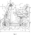
- FIG. 2 is a side view of the vehicle 1 shown in FIG. 1 .
- FIG. 3 is a top view of the vehicle 1 shown in FIG. 1 .
- the ratio of the diameter Rf of the front wheels 8f to the total length L0 of the vehicle 1 as measured in the front-rear direction is not less than 0.26 (0.26 ⁇ Rf/LO). Providing such a ratio of the diameter of the front wheels to the total length improves the ability to handle a groove and ride over a step.
- the vehicle is capable of riding over an obstacle of about 5 cm, for example, with ease.
- the inventors have further discovered that, if 0.28 ⁇ Rf/LO, the vehicle is capable of riding over a step of 5 cm by obliquely entering the relevant location, and also capable of riding over a curbstone of 10 cm.
- the diameter Rb of the rear wheels 8b is not limited to any particular value, it may be, for example, similarly to the front wheels 8f, 0.26 ⁇ Rb/L0, preferably 0.27 ⁇ Rb/L0, and more preferably 0.28 ⁇ Rb/L0. This improves road-handling performance.
- the seat 4 in a construction with 0.26 ⁇ _ Rb/L0, is constructed such that the portion thereof on which the thighs of the occupant are to be placed is located higher than the portion on which the buttocks of the occupant are to be placed.
- the footboard 3 is constructed such that the rearmost point 3bp of the surface on which the feet are to be placed is located rearward of the forwardmost point 4fp of the upper surface 4u of the seat 4. This allows the occupant to ride in a natural posture while providing a sufficient road-handling performance of the vehicle 1.
- the portion 4ua of the seat 4 on which the buttocks of the occupant are to be placed is indicated by dots.
- the position of the middle of the seat 4 as determined along the front-rear direction is indicated by line K1
- the position of the middle of the seat 4 as determined along the left-right direction is indicated by line K5.
- the middle of the seat 4 as determined along the front-rear direction in a top view is indicated by an imaginary line extending in the left-right direction along the middle between the forwardmost point 4fp and rearmost point 4bp of the upper surface 4u of the seat 4, as indicated by line K1.
- a region of the seat 4 that contains the middle along the left-right direction and includes portions located rearward of the middle K1 along the front-rear direction constitutes the portion 4ua on which the buttocks are to be placed. That is, a region of the seat 4 that includes an area located rearward of the middle K1 of the upper surface 4u along the front-rear direction and does not contact the left and right edges nor the front edge of the upper surface 4u of the seat 4 constitutes the portion 4ua on which the buttocks are to be placed. A region located forward of the portion 4ua on which the buttocks are to be placed constitutes the portion 4ub on which the thighs are to be placed.
- the portion for the thighs is part of a region extending from the portion 4ua for the buttocks all the way to the forwardmost point 4fp of the upper surface 4u of the seat 4 and in contact with the portion 4ua for the buttocks.
- the height of the upper surface of the seat 4 as measured at the portion 4ua of the seat 4 on which the buttocks of the occupant are to be placed is less than the height of the upper surface of the seat 4 as measured at the portion 4ub on which the thighs are to be placed.
- the upper surface 4u of the seat 4 may include a portion that is inclined so as to rise as it goes forward from a region rearward of the middle K1 of the seat 4 along the front-rear direction to a region located forward of the middle K1 along the front-rear direction.
- the portion 4ub for the thighs is located higher than the portion 4ua for the buttocks.
- implementations where the portion for the thighs is located higher than the portion for the buttocks are not limited to such implementations where the upper surface 4u of the seat 4 is inclined.
- the upper surface 4u of the seat 4 may be constructed so as to rise stepwise from a position rearward of the middle K1 along the front-rear direction to a position forward of the middle.
- the forwardmost point 4fp of the upper surface 4u of the seat 4 is defined as the forwardmost point of the sitting cushion
- the rearmost point 4bp of the upper surface 4u of the seat 4 is defined as the rearmost point of the sitting cushion.
- the angle ⁇ S of the upper surface 4u of the seat 4 relative to the horizontal plane in a side view may be 7° ⁇ ⁇ s, as shown in FIG. 2 .
- the angle ⁇ S is preferably 8° ⁇ ⁇ S, and more preferably 8.6 ⁇ ⁇ S.
- the angle ⁇ S may be ⁇ S ⁇ 15°.
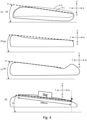
- FIG. 4 illustrates how to calculate the angle ⁇ S.
- Line 4-1 in FIG. 4(a) indicates an exemplary shape, in a side view, of a portion of the seat 4 shown in FIG. 2 at the middle along the left-right direction. If a straight line dominating the angle of the upper surface of the seat can be defined in a region of the upper surface of the seat where the buttocks and thighs are to be placed, as shown in FIG. 4(a) , then, the angle between that straight line and the horizontal plane is treated as ⁇ S.
- the straight line used to determine the angle is a straight line in a plane perpendicular to the left-right direction of the vehicle.
- the dominating straight line is a line that conforms to the shape of the upper surface of the seat to some degree and can approximate the line of the upper surface of the seat.
- line 4-1 indicates the shape of a cross section of the region 4ua on which the buttocks are to be placed (i.e., along imaginary line K5 of the middle as determined along the left-right direction (see FIG. 3 )).
- Line 4-2 indicates the shape of a cross section of protrusions, outward in the left-right direction, of the region 4ua on which the buttocks are to be placed.
- FIG. 4(b) shows an exemplary implementation with a seat with a recessed upper surface.
- a straight line connecting the peaks on both sides of the recess can be defined.
- the angle of such a straight line defined by both peaks relative to the horizontal plane is treated as ⁇ S.
- FIG. 4(c) shows an exemplary implementation with a seat with an upper surface including a projection.
- the angle of a dominating straight line defined by portions excluding the projection relative to the horizontal plane is treated as ⁇ S.
- a projection of the upper surface of the seat outside the region where the buttocks and thighs are to be placed is not taken into account when the angle ⁇ S is calculated.
- FIG. 4(d) shows an exemplary implementation with a seat with a generally protruding upper surface where no straight line dominating the angle can be defined.
- a smooth plate with a dimension in the left-right direction of the vehicle of 200 mm and a dimension in the front-rear direction of the vehicle of 300 mm is placed on the upper surface of the seat, a weight of 3 kg is put on the middle of the plate for stabilization, and the angle of the upper surface of the plate in this state relative to the horizontal plane is measured, which is treated as ⁇ S.
- the plate is positioned such that the middle of the plate as determined along the left-right direction is aligned with the middle of the upper surface of the seat as determined along the left-right direction and that the rear edge of the plate falls on the rearmost point of the region of the upper surface of the seat where the buttocks of the occupant can actually be placed.
- the inclination of the portion 4ua of the upper surface 4u of the seat 4 on which the buttocks are placed need not be constant.
- the portion 4ua where the buttocks are placed may be locally recessed to be located lower than the portion 4bu for the thighs.
- the rearmost point 3bp of the surface of the footboard 3 on which the feet are placed is located rearward of the forwardmost point 4fp of the upper surface 4u of the seat 4. This creates a space below the seat 4 to allow the occupant to place his/her feet below the seat 4. This makes it easier for the occupant to assume a posture with the upper part of his/her body being upright.
- FIG. 5 illustrates the posture of the occupant on the one-occupant electric vehicle 1 according to the present embodiments.
- FIG. 5(a) shows an occupant riding the vehicle 1 shown in FIGS. 1 to 3 .
- FIG. 5(b) shows an occupant riding a conventional one-occupant electric vehicle 80A.
- the above-described construction of the seat 4 and footboard 3 allows the thighs of the occupant sitting on the seat to rise upward of the buttocks. The occupant, while sitting, naturally pulls his/her heels rearward and raises the upper part of the body closer to upright. As a result, the lower legs of the occupant are generally parallel to the upper part of his/her body.
- the pelvis of the occupant is upright and the backbone is curved in an S-shape.
- This posture is easy and natural for the occupant.
- This posture is also preferable from a health perspective.
- the occupant assumes a posture with the upper part of his/her body inclined rearward and leaning against the backrest seat.
- the lower legs of the occupant are oblique with the feet thrown forward.
- the pelvis of the occupant is inclined rearward and the backbone is curved in a C-shape.
- the vehicle 1 is constructed such that the dimension of the space for the occupant as measured in the front-rear direction can be reduced.
- the seat and footboard are constructed so as to naturally accommodate the occupant even when the knees are bent generally at an angle of 90° or less. This makes it possible to increase the diameter Rf of the front wheels 8f. As a result, it is possible to provide both road-handling performance and comfort. Further, a construction that increases the road-handling performance of the vehicle and makes it easier for the occupant to ride in an upright posture allows the occupant to enjoy an operation that gives him/her a feel of independence.
- the footboard 3 is located between the handlebar 7 and the seat 4 as determined along the front-rear direction of the vehicle 1.
- the rearmost point 7bp of the grips 7a of the handlebar 7 is located rearward of the forwardmost point 3fp of the surface of the footboard 3 on which the feet are placed.
- the distance in the front-rear direction of the vehicle 1 between the rearmost point 7bp of the grips 7a of the handlebar 7 and the forwardmost point 3fp of the surface of the footboard 3 on which the feet are placed, La may be, for example, 40 to 140 mm, although the distance is not limited to this range.
- the distance in the front-rear direction of the vehicle between the forwardmost point 3fp of the surface of the footboard 3 on which the feet are placed and the forwardmost point 4fp of the upper surface 4u of the seat 4, Lb, may be 320 to 360 mm, for example, although this distance is not limited to this range.
- the surface of the footboard 3 on which the feet are placed is the upper surface of the footboard 3.
- the surface on which the feet are placed need not be a flat surface. In the present embodiments, by way of example, the entire surface of the footboard 3 on which the feet are placed is parallel to the horizontal plane.
- the angle ⁇ A formed by an imaginary line K2 connecting the rearmost point 7bp of the grips 7a of the handlebar 7 at a steering angle of 0° and the forwardmost point 3fp of the surface of the footboard 3 on which the feet are placed, on the one hand, and an imaginary line K3 connecting the rearmost point 7bp of the grips 7a of the handlebar 7 and the rearmost point 4bp of the upper surface 4u of the seat 4, on the other, may be ⁇ A ⁇ 75°.
- the distance in the top-bottom direction of the vehicle 1 between the rearmost point 4bp of the upper surface 4u of the seat 4 and the uppermost point 7up of the grips 7a of the handlebar, Ha, 7 may be, for example, 300 mm ⁇ Ha ⁇ 450 mm, although this distance is not limited to this range. This makes it easier for the occupant sitting on the seat 4 and grasping the grips 7a to support a posture with the upper part of the body straightened up using his/her arms.
- the distance in the top-bottom direction of the vehicle between the uppermost point 4up of the upper surface 4u of the seat 4 and the surface of the footboard 3 on which the feet are placed, H10, may be not smaller than 405 mm, for example. This provides a sufficient height of the seat 4, i.e., leg height, for allowing the occupant sitting on the seat 4 to get his/her lower legs vertical. If the surface of the footboard 3 on which the feet are placed is not horizontal, the distance from the highest position of the surface on which the feet are placed to the uppermost point 4up of the upper surface 4u of the seat 4 is treated as H10.
- the vehicle 1 further includes a backrest seat 6 that supports the back of the occupant.
- the backrest seat 6 is coupled to the rearmost point 4bp of the upper surface 4u of the seat 4.
- the backrest seat 6 extends upward from the rearmost point 4bp of the upper surface 4u of the seat 4.
- the front surface 6f of the backrest seat 6 may include a portion located above the seat 4 that extends forward of the rearmost point 4bp of the upper surface 4u of the seat 4. This allows the back of the occupant sitting on the seat 4 to be supported at a position forward of the rearmost point 4bp of the upper surface 4u of the seat 4 (see FIG. 5(a) ).
- the backrest seat 6 supports the upright posture of the upper part of the body of the occupant.
- the backrest seat 6 includes a backrest cushion 61 and a back support body 62 that supports the backrest cushion 61.
- the backrest cushion 61 is held by the back support body 62 to be separated from the upper surface 4u of the seat 4 and to be at least partially located forward of the rearmost point 4bp of the upper surface 4u of the seat 4.
- the front surface of the backrest cushion 61 represents the front surface 6f of the backrest seat 6 to support the back of the occupant.
- the back support body 62 may be formed integrally with the seat support body that supports the sitting cushion of the seat 4.
- the rearmost point 6bp of the backrest seat 6 is located forward of the rearmost point 8bbp of the rear wheels 8(b). This construction prevents the back of the occupant sitting on the seat 4 from being located rearward of the rearmost point 8bbp of the rear wheels 8b.
- the portion of the upper surface 4u of the seat 4 on which the buttocks of the occupant are placed overlaps an imaginary line K6 that perpendicularly passes through the axle bwj of the rear wheels 8b.
- the occupant by getting the upper part of the body upright above the rear wheels 8, can have an increased feel of being integrated with the vehicle 1. This same effect can also be produced in implementations where the rearmost point 6bp of the backrest seat 6 is at the same position as the rearmost point 8bbp of the rear wheels 8b as determined along the front-rear direction of the vehicle 1.
- the entire backrest seat 6 is located rearward of the axle bwj of the rear wheels 8b.
- the seat 4 overlaps imaginary line K6 that passes perpendicularly through the axle bwj of the rear wheels 8b.
- the occupant, sitting on the seat 4, and getting the upper part of the body upright above the rear wheels 8b, can have an increased feel of being integrated with the vehicle 1.
- the position of the middle of the seat 4 as determined along the left-right direction is indicated by imaginary line K5.
- the distance in the front-rear direction of the vehicle 1 between the rearmost point 4bp of the upper surface 4u of the seat 4 and the forwardmost point 6fcp of the front surface 6f of the backrest seat 6, Lc may be, for example, 40 mm ⁇ Lc ⁇ 60 mm.
- the middle of the seat 4 as determined along the front-rear direction of the vehicle, indicated by imaginary line K1, is located rearward of the forwardmost point of the rear wheels 8b.
- imaginary line K6 the portion of the upper surface 4u of the seat 4 on which the buttocks of the occupant are placed overlaps imaginary line K6 that passes perpendicularly through the axle bwj of the rear wheels 8b.
- the vehicle 1 further includes armrests 5.
- the armrests 5 are provided to the left and right of the seat 4.
- the armrests 5 are attached to the sides of the seat 4.
- the armrests 5 extend upward from the sides of the seat 4.
- An upper portion of each armrest 5 forms a stand that extends in the front-rear direction.
- the top surface of each stand is a flat surface.
- Each armrest 5 may be attached to the seat to be rotatable about an axis extending in the left-right direction.
- the distance in the top-bottom direction of the vehicle between the rearmost point 4bp of the upper surface 4u of the seat 4 and the uppermost point of the armrests 5, H1, may be, for example, H1 ⁇ 200 mm.
- the elbows of the occupant are less likely to hit the armrests 5 during his/her operation on the handlebar.
- the armrests 5 do not hamper the operation.
- the armrests 5 of this construction are not intended to allow the elbows to be placed thereon during the occupant's operation on the handlebar.
- the distance H1 may be not larger than 2/3 of the distance Ha in the top-bottom direction of the vehicle 1 between the rearmost point 4bp of the upper surface 4u of the seat 4 and the uppermost point 7up of the grips 7a of the handlebar 7 (H1 ⁇ Ha ⁇ (2/3)). In this construction, too, the elbows of the occupant are less likely to hit the armrests when the occupant grasps the grips 7a and operates the handlebar.
- FIG. 6 is a cross-sectional view of the seat and backrest seat of FIG. 3 taken along line V-V.
- the seat 4 includes a sitting cushion 401 and a seat support body 402 that supports a lower portion of the sitting cushion 401.
- the sitting cushion includes a plurality of cushion materials 411 to 413 with different impact resiliences.
- the cushion material with high impact resilience 413 is positioned in the portion of the cushion on which the buttocks of the occupant are placed.
- the impact resilience of the cushion material 413 is higher than the impact resiliences of the other cushion materials 411 and 412.
- Cushion material having high impact resilience means a hard cushion, or a cushion with high elasticity.
- Non-limiting examples of cushion materials with high impact resilience include materials of closed cell structure or foamed silicone.
- the impact resilience of a cushion material is determined by the method of determining impact resilience specified by JIS K6500-3:2011.
- the region in which the cushion material with high impact resilience 413 is positioned is the portion of the seat 4 on which the buttocks of the occupant are placed, i.e., the portion on which the weight of the occupant is concentrated.
- the cushion material with a higher impact resilience 413 may be positioned rearward of the middle K1 of the seat 4 as determined along the front-rear direction, extending across the middle K5 as determined along the left-right direction and not in contact with the left nor right edges nor the front edge of the seat 4.
- the occupant sitting on the seat 4 can easily get the upper part of his/her body upright.
- the weight of the occupant tends to be concentrated on the portion of the seat 4 on which the buttocks of the occupant are placed.
- the entire sitting cushion of the seat 4 is relatively soft.
- the weight is concentrated on a limited portion and, when the load exceeds a threshold, hardness is suddenly felt. In this case, the occupant has the feel of bottom-hitting.
- the sink-in at the location of load concentration is mitigated by positioning the cushion material 413 with a higher impact resilience than the other cushion materials 411 and 412 within the portion 4ua of the sitting cushion 401 where the buttocks are placed, as shown in FIG. 6 .
- the cushion material with high impact resilience 413 may be positioned to overlie another cushion material 412 with a lower impact resilience such that these materials are arranged in the top-bottom direction of the vehicle 1. This mitigates the sink-in at the location of load concentration while retaining softness.
- the cushion material with a higher impact resilience 413 is positioned between the cushion materials with lower impact resiliences 411 and 412 such that all these materials are arranged in the top-bottom direction of the vehicle 1.
- the portion 4ua of the sitting cushion 401 of the seat 4 on which the buttocks of the occupant are placed includes three stacked cushion materials 412, 413 and 411.
- the impact resilience of the middle one of the three layers is higher than the impact resiliences of the other layers, i.e., this layer is harder and more elastic than the other layers.
- the cushion material with high impact resilience 413 is positioned between the cushion materials with low impact resilience 411 and 412.
- the other portions of the sitting cushion 401 are provided by the cushion materials with low impact resilience 411 and 412.
- the portion of the sitting cushion 401 on which the load is concentrated is also recessed only to some degree and deforms with the surrounding portions. This makes it possible to achieve both the reduction of sink-in and the improvement of the feel of being held.
- FIG. 7 is a graph illustrating exemplary relationships between the load on the cushion made of a plurality of stacked cushion materials with different impact resiliences, on the one hand, and the amount of sink-in, on the other.
- the examples shown in FIG. 7 show such relationships for structures A and B, which each have two layers stacked in the load direction, one being a hard cushion layer with high elasticity and the other being a soft cushion layer with low elasticity, and a structure C with three layers, where a hard layer is positioned between soft layers.
- the graph of FIG. 7 shows that, if a cushion with high elasticity is placed on top of a cushion with low elasticity (i.e., forms a top layer), as in structure A, the amount of sink-in in response to a load is small from the beginning.
- the occupant feels hardness. If the lower layer is hard and the upper layer is soft, as in structure B, the occupant feels softness at the beginning but suddenly feels hardness at an early point of time. The occupant has the feel of bottom-hitting, where sink-in suddenly stops. If a cushion with high elasticity is placed in the middle of a three-layer structure, as in structure C, hardness gradually increases with increased load. In this case, it is possible to achieve all of softness at the beginning, the prevention of the feel of stroke at an intermediate stage, and the prevention of the feel of bottom-hitting at the end.
- the vehicle 1 includes a vehicle-body frame 2.
- the vehicle-body frame 2 includes a lower frame portion 24 at a lower location of the vehicle 1 extending in the front-rear direction, a down tube 21 coupled to a front portion of the lower frame portion 24, a head pipe 22 attached to a front portion of the down tube 21, a front frame portion 23 located forward of the lower frame portion 24, and a seat frame portion 25 extending upward from a rear portion of the lower frame portion 24 to support the seat 4.
- the head pipe 22 rotatably supports the steering axle 26.
- the handlebar 7 is attached to the top of the steering axle 26.
- One end of each of arms 41 and 42 is rotatably attached to the front frame portion 23.
- the other ends of the arms 41 and 42 are rotatably attached to a knuckle arm 47.
- the knuckle arms 47 rotatably support the front wheels 8f.
- the arms 41 and 42 include pairs of arms 41 and 42 disposed at the top and bottom. Coupled to the bottom of the steering axle 26 is a pitman arm 49 that rotates together with the steering axle 26.
- the pitman arm 49 is coupled to the knuckle arms 47, with a tie rod (not shown) provided therebetween.
- the rotation of the steering axle 26 is transmitted to the front wheels 8f via the pitman arm 49, tie rod and knuckle arms 47.
- Front suspensions 43 are provided between the arms 41 and vehicle-body frame 2 (i.e., head pipe 22 in the implementations of FIG. 2 ). One end of each front suspension is rotatably attached to the vehicle-body frame 2, while the other end is rotatably attached to the associated arm 41.
- the front suspensions 43 and arms 41 and 22 constitute an independent front suspension system.
- the front suspension system may be, for example, a wishbone suspension.
- the front wheels 8f are implemented as two wheels disposed to the left and right.
- a pair of arms 41 and 42, a knuckle arm 47 and a front suspension 43 are provided for each of the two front wheels 8f to the left and right.
- the vehicle 1 further includes a rear arm 51.
- the rear arm 51 is attached to the vehicle-body frame 2 to be rotatable about a pivot shaft 56, and rotatably supports a rear wheel 8b.
- a rear suspension 53 is provided between the vehicle-body frame 2 (i.e., seat frame portion 25 in the implementations of FIG. 2 ) and the rear arm 51.
- One end of the rear suspension 53 is rotatably attached to the vehicle-body frame 2, while the other end is rotatably attached to the rear arm 51.
- the rear suspension 53 and rear arm 51 constitute an independent rear suspension system.
- the rear suspension system may be, for example, a trailing arm suspension.
- the front and rear suspensions 43 and 53 are axially extendable shock absorbers, and include a coil spring and a damper, for example.
- the location at which an upper portion of the rear suspension 53 is attached to the vehicle-body frame 2 is located forward of the middle K1 of the seat 4 as determined along the front-rear direction in a side view of the vehicle 1. That is, the axis of rotation of the upper portion of the rear suspension 53 is located forward of the middle K1 of the seat 4 as determined along the front-rear direction.
- the rear suspension 53 When the rear suspension 53 is contracted or extended, the rear suspension 53 rotates relative to the vehicle-body frame 2 about the axis of rotation located forward of the middle K1 of the seat 4 as determined along the front-rear direction.
- the axis of rotation is positioned near the thighs of the occupant sitting on the seat 4. This makes it easier for the occupant to keep a natural posture.
- the rear suspension 53 is inclined forward such that an upper portion thereof is located forward of a lower portion when the suspension is extended to the maximum. That is, the attachment position of the upper portion of the rear suspension 53 is located forward of the attachment position of the lower portion thereof. Thus, the attachment position of the upper portion of the rear suspension 53 is located close to the thighs of the occupant sitting on the seat 4.
- the vehicle 1 includes an independent front suspension system and an independent rear suspension system. This improves the ability to follow irregularities of the road surface. Further, it increases the ability of the vehicle 1 to turn.
- a motor 9 is provided on the rear arm 51.
- the motor 9 is an in-wheel motor.
- the motor 9 drives the rear wheel 8b.
- An output shaft of the motor 9 is coupled to the rear wheel 8b via a gear (not shown).
- the rear wheel 8b is implemented as two wheels disposed to the left and right.
- a pair of rear arms 51, a rear suspension 53, and a motor 9 are provided for each of the two rear wheels 8b to the left and right.
- a motor 9 may only be provided on one of the two rear wheels 8b to the left and right.
- a motor may be provided on the front wheel 8f.
- the one-occupant electric vehicle 1 is a four-wheel, handled electric wheelchair.
- the one-occupant electric vehicle 1 is not limited to a four-wheel, handled electric wheelchair as illustrated herein.
- the one-occupant electric vehicle 1 may be, for example, a joystick electric wheelchair.
- the one-occupant electric vehicle 1 is not limited to an electric wheelchair; in other implementations, it may be a one-occupant carrier wagon or electric cart, for example.
- the number of wheels may be three or four or more. For example, in lieu of two rear wheels, one wheel may be provided.
Landscapes
- Engineering & Computer Science (AREA)
- Mechanical Engineering (AREA)
- Health & Medical Sciences (AREA)
- Life Sciences & Earth Sciences (AREA)
- Animal Behavior & Ethology (AREA)
- General Health & Medical Sciences (AREA)
- Public Health (AREA)
- Veterinary Medicine (AREA)
- Automatic Cycles, And Cycles In General (AREA)
Abstract
Description
- The present invention relates to a one-occupant electric vehicle.
- One known example of a one-occupant electric vehicle is a handled electric wheelchair. A handled electric wheelchair is sometimes also referred to as "Senior Car" (registered trademark). For example,
JP 2020-048611 A Patent Document 1 listed below) discloses a one-occupant electric vehicle with improved driving performance. This one-occupant electric vehicle includes a seat that allows an occupant to sit thereon, armrests, a footboard that allows the occupant to place his/her feet thereon, a wheel set including four wheels, an electric motor that drives the wheels, an independent front suspension that supports the front wheels, and an independent rear suspension that supports the rear wheels. - Patent Document 1:
JP 2020-048611 A - A one-occupant electric vehicle provided with large-sized front wheels provides increased road-handling performance on an unpaved road and/or a step. On the other hand, increasing the diameter of the front wheels tends to narrow the space where the occupant can place his/her feet. As a result, the occupant may feel cramped.
- The present application discloses a one-occupant electric vehicle that allows the occupant to ride in a natural posture while providing sufficient road-handling performance.
- A one-occupant electric vehicle according to embodiments of the present invention includes: a seat adapted to allow an occupant to sit thereon; a footboard adapted to allow the occupant to place a foot thereon; a wheel set including at least two front wheels and at least one rear wheel; and a motor adapted to drive at least one wheel of the wheel set. A ratio of a diameter Rf of the front wheels to a total length L0 of the one-occupant electric vehicle as measured in a front-rear direction of the vehicle is not less than 0.26 (0.26 ≤ Rf/LO); and a portion of the seat on which a thigh of the occupant is to be placed is located higher than a portion of the seat on which a buttock of the occupant is to be placed, and a rearmost point of a surface of the footboard on which the foot is to be placed is located rearward of a forwardmost point of an upper surface of the seat.
- The present disclosure provides a one-occupant electric vehicle that allows the occupant to ride in a natural posture while providing sufficient road-handling performance.
-
- [
FIG. 1] FIG. 1 is a perspective view of a one-occupant electric vehicle according to the present embodiments, showing an exemplary construction. - [
FIG. 2] FIG. 2 is a side view of the vehicle shown inFIG. 1 . - [
FIG. 3] FIG. 3 is a top view of the vehicle shown inFIG. 2 . - [
FIG. 4] FIG. 4 illustrates how to calculate the angle of the upper surface of the seat. - [
FIG. 5] FIG. 5 illustrates the posture of the occupant on the vehicle according to the present embodiments. - [
FIG. 6] FIG. 6 is a cross-sectional view of the vehicle, taken along line V-V ofFIG. 3 . - [
FIG. 7] FIG. 7 is a graph showing relationships between a load on, and sink-in of, stacked cushion materials of the seat. - A one-occupant electric vehicle provided with large-sized front wheels provides increased road-handling performance on an unpaved road and/or a step. Particularly, the inventors have discovered that increasing the diameter of the front wheels improves road-handling performance. For example, increasing the diameter of the front wheels makes it easier to ride over a step and/or overcome a groove and/or irregularities on the road surface. On the other hand, increasing the diameter of the front wheels tends to narrow the space where the occupant can place his/her feet. For example, a narrower space for the feet could make the occupant feel cramped, which means decreased comfort. In view of this, the inventors investigated a way to improve road-handling performance taking account of occupant comfort. The inventors conducted extensive research into seat and footboard constructions, and discovered an arrangement that allows the occupant to drive in a natural posture even with a narrow space for the feet.
- A one-occupant electric vehicle according to embodiments of the present invention includes: a seat adapted to allow an occupant to sit thereon; a footboard adapted to allow the occupant to place a foot thereon; a wheel set including at least two front wheels and at least one rear wheel; and a motor adapted to drive at least one wheel of the wheel set. A ratio of a diameter Rf of the front wheels to a total length L0 of the one-occupant electric vehicle as measured in a front-rear direction of the vehicle is not less than 0.26 (0.26 ≤ Rf/LO); and a portion of the seat on which a thigh of the occupant is to be placed is located higher than a portion of the seat on which a buttock of the occupant is to be placed, and a rearmost point of a surface of the footboard on which the foot is to be placed is located rearward of a forwardmost point of an upper surface of the seat.
- In the above described arrangement, the diameter of the front wheels of the one-occupant electric vehicle is not less than 0.26 times the total length of the vehicle, thus providing sufficient road-handling performance. Since the portion of the seat on which the thighs of the occupant are to be placed is located higher than the portion on which the buttocks of the occupant are to be placed, the thighs of the occupant sitting on the seat are raised upward relative to the buttocks. This allows the occupant to naturally pull the heels rearward so that he/she can sit with the upper part of his/her body close to upright. As a result, the lower legs of the occupant are generally parallel to the upper part of the body. This achieves an easy and comfortable posture for the occupant. This provides a one-occupant electric vehicle that allows the occupant to ride in a natural posture while providing sufficient road-handling performance.
- As Rf/LO increases, the wobbliness of the one-occupant electric vehicle during traveling decreases, thereby improving the ride-over performance against a groove and a step. This improves the ride comfort of the one-occupant electric vehicle. However, if Rf/LO is increased while the total length of the one-occupant electric vehicle remains the same as measured in the front-rear direction, this means a narrower space for the occupant, which reduces occupant comfort. As such, it is difficult to increase Rf/LO with conventional techniques. With the above-described arrangement, the occupant can assume an easy posture even when 0.26 ≤ Rf/LO, thereby providing sufficient comfort. Rf/LO is more preferably 0.27 ≤ Rf/LO, and yet more preferably 0.28 ≤ Rf/LO. Although no particular upper limit for Rf/LO is specified, an example may be Rf/LO ≤ 0.45.
- By way of example, in a side view of the vehicle, the angle θS of the upper surface of the seat relative to the horizontal plane may be 7° ≤ θS. This makes it easier for the occupant to assume a posture where the lower legs and the upper part of the body are upright. In this respect, the angle θS is preferably 8° ≤ θS, and more preferably 8.6 ≤ θS. To support an upright posture, the angle θS may be θS ≤ 15°, for example.
- In the one-occupant electric vehicle, the surface of the footboard on which the foot is to be placed may be constructed so as not to include a portion located upward of the front wheels in a side view. Thus, an area on which the occupant can place his/her feet is not positioned upward of the front wheels, which makes it easier for the occupant to assume a posture with the heels pulled rearward and the upper part of the body upright. In the same respect, the footboard may be constructed such that the forwardmost point of the surface of the footboard on which the foot is to be placed is located rearward of the front wheels.
- In implementations where the positioning of the seat of the one-occupant electric vehicle is adjustable, the positions of the forwardmost point and the rearmost point of the upper surface of the seat are defined as the forwardmost point and the rearmost point of the upper surface of the seat as found when the seat is adjusted to be positioned rearmost within the adjustment range.
- The one-occupant electric vehicle may further include a handlebar used to steer the front wheels. At least a portion of the footboard may be located between the handlebar and the seat as determined along the front-rear direction of the vehicle. When a steering angle of the handlebar is 0°, a rearmost point of a grip of the handlebar may be located rearward of a forwardmost point of a footboard and a distance between the rearmost point of the grip of the handlebar and a forwardmost point of the surface of the footboard on which the foot is to be placed as measured in the front-rear direction of the vehicle, La, may be not larger than 140 mm. This allows the positions at which the feet are to be placed to be closer to the positions of the grips as measured in the front-rear direction. This makes it easier for the occupant to maintain a posture with the upper part of the body being upright while grasping the grips.
- In this respect, the distance La is preferably La ≤ 100 mm, and more preferably La ≤ 90 mm. Further, to achieve an appropriate relationship between the grip positions and the positions for the feet in the front-rear direction, for example, preferably La ≥ 50 mm, and more preferably La ≥ 70 mm.
- A distance between a forwardmost point of the surface of the footboard on which the foot is to be placed and the forwardmost point of the upper surface of the seat as measured in the front-rear direction of the vehicle, Lb, may be not larger than 360 mm. This reduces the space in which the lower legs of the occupant are positioned as measured in the front-rear direction, making it possible to increase the diameter of the front wheels while keeping the total length within a predetermined range. Further, this results in the occupant sitting on the seat with the lower legs upright, making it easier to naturally maintain a posture with the lower legs and the upper part of the body being upright.
- In the same respect, preferably Lb ≤ 350 mm, and more preferably La ≤ 340 mm. The ratio of the distance Lb to the total length L0 is preferably Lb/LO ≤ 0.30, more preferably Lb/LO ≤ 0.29, and yet more preferably Lb/LO ≤ 0.28. Further, to provide a sufficient space for the feet, preferably Lb ≥ 320 mm, and more preferably La ≥ 330 mm.
- The one-occupant electric vehicle may further include a handlebar used to steer the front wheels. When a steering angle of the handlebar is 0°, in a side view of the vehicle, an angle formed by an imaginary line connecting a rearmost point of a grip of the handlebar and a forwardmost point of the surface of the footboard on which the foot is to be placed, on the one hand, and an imaginary line connecting the rearmost point of the grip of the handlebar and a rearmost point of the upper surface of the seat, on the other, θA, may be θA ≤ 75°. Setting such a positional relationship among the handlebar, footboard and seat makes it easier for the occupant sitting on the seat and grasping the handlebar to assume a posture with the lower legs and the upper part of the body being upright and parallel to each other.
- In the same respect, preferably θA ≤ 73°, and more preferably θA ≤ 70°. Further, preferably θA ≥ 60°, and more preferably θA ≤ 65°.
- A distance between an uppermost point of the upper surface of the seat and the surface of the footboard on which the foot is to be placed as measured in the top-bottom direction of the vehicle, H10, may be not smaller than 405 mm. This provides a sufficient height of the space in which the lower legs of the occupant can be positioned. This makes it easier for the occupant to naturally pull the heels rearward to get the upper part of the body upright. In the same respect, preferably H10 ≥ 410 mm, and more preferably H10 ≥ 414mm. Further, to achieve an appropriate height of the space for the lower legs of the occupant, preferably H10 ≤ 430mm, and more preferably H10 ≤ 420 mm.
- The one-occupant electric vehicle may further include a backrest seat adapted to support a back of the occupant. A front surface of the backrest seat may include a portion located above the seat and extending forward of a rearmost point of the upper surface of the seat. This arrangement allows the back of the occupant sitting on the seat to be supported at a location forward of the rearmost point of the upper surface of the seat. This helps the occupant to get the upper part of his/her body upright.
- The backrest seat may include a backrest cushion and a back support body supporting the backrest cushion. The backrest cushion may be held by the back support body so as to be separated from the upper surface of the seat. At least a portion of the backrest cushion may be located forward of the rearmost point of the upper surface of the seat. This enables efficiently positioning the backrest cushion that helps the occupant to assume an upright posture.
- The one-occupant electric vehicle may further include a handlebar used to steer the front wheels; and an armrest provided to at least one of the left or right of the seat. A distance between a rearmost point of the upper surface of the seat and an uppermost point of the armrest as measured in a top-bottom direction of the vehicle, H1, may be not larger than 2/3 of a distance between the rearmost point of the upper surface of the seat and an uppermost point of a grip of the handlebar as measured in the top-bottom direction of the vehicle, Ha (H1 ≤ Ha×(2/3)). With this arrangement, when the occupant grasps the grips and operates the handlebar, an elbow of the occupant is less likely to contact the armrest. The occupant can operate the handlebar without placing an elbow on the armrest. As such, the occupant can actively operate the handlebar, for example. In this respect, more preferably H1 < Ha×(2/3), yet more preferably H1 ≤ Ha×(5/12), and still more preferably H1 ≤ Ha×(1/2).
- The one-occupant electric vehicle may further include a handlebar used to steer the front wheels. A distance between a rearmost point of the upper surface of the seat and an uppermost point of a grip of the handlebar as measured in the top-bottom direction of the vehicle, Ha, may be Ha ≥ 300 mm. Such a large height between the sitting surface and the grips of the handlebar makes it easier for the occupant to support a posture with the upper part of the body straightened up using his/her arms. This reduces the fatigue of the trunk. Further, it allows more movement of the muscles of the back and trunk of the occupant when steering. In this respect, preferably Ha ≥ 350 mm, and more preferably Ha ≥ 360 mm. Further, to achieve an appropriate height of the grip positions, for example, preferably Ha ≤ 450 mm, and more preferably Ha ≥ 400 mm.
- If the armrest is movably attached to the seat, the positioning and construction of the armrest is defined as the positioning and construction of the armrest as found when it is located lowest as determined along the top-bottom direction of the vehicle.
- The one-occupant electric vehicle may further include an armrest provided to at least one of the left or right of the seat. A distance between a rearmost point of the upper surface of the seat and an uppermost point of the armrest as measured in a top-bottom direction of the vehicle, H1, may be H1 < 200 mm. This ensures that there is a wide range in which the occupant can move his/her arms while sitting on the seat. For example, the occupant can easily operate the handlebar without getting in contact with the armrest. In this respect, preferably H1 < 195 mm, more preferably H1 < 190 mm, and yet more preferably H1 < 185 mm. To provide a sufficient height of the armrest, preferably H1 ≥ 160 mm, and more preferably H1 ≥ 170 mm.
- The seat may include a sitting cushion. The sitting cushion may include a plurality of cushion materials with different impact resiliences (different amounts of impact resilience). In such implementations, one of the cushion materials positioned at a location where the buttock of the occupant is to be placed may have a higher impact resilience than other cushion materials positioned at other locations of the seat. When the occupant sits on the seat with the upper part of the body upright, the weight of the upper part of the body is concentrated on the portion for the buttocks. In view of this, creating a cushion arrangement where the portion on which the buttocks of the occupant are to be placed has a higher impact resilience than the other portions enables adjusting the amount of sink-in of the portion for the buttocks so as to create an appropriate pressure to give an appropriate feel of being held, thereby making it easier for the occupant to maintain his/her posture.
- In the sitting cushion of the seat, the cushion material positioned at the location where the buttock of the occupant is to be placed may include three stacked layers of cushion materials. An impact resilience of a middle one of the three layers may be higher than impact resiliences of other layers. This provides a sufficient sitting comfort for the occupant while minimizing the sink-in. Specifically, the occupant is less likely to feel the hardness of the surface of the sitting cushion, and also less likely to have the feel of bottom-hitting, where the occupant suddenly feels hardness after reaching a certain amount of sink-in.
- The one-occupant electric vehicle may further include a backrest seat adapted to support a back of the occupant. As determined along the front-rear direction of the vehicle, a rearmost point of the backrest seat may be at the same position as a rearmost point of the rear wheel or forward of the rearmost point of the rear wheel. Thus, even in implementations with a large rear wheel, the rear wheel and backrest seat can be efficiently positioned within a limited total length.
- The one-occupant electric vehicle may further include a backrest seat adapted to support a back of the occupant. The backrest seat may be located rearward of an axle of the rear wheel. Thus, even in implementations with a large rear wheel, the rear wheel and backrest seat can be efficiently positioned within a limited total length.
- A middle of the seat as determined along the front-rear direction of the vehicle may be located rearward of a forwardmost point of the rear wheel. Thus, even in implementations with a large rear wheel, the rear wheel and backrest seat can be efficiently positioned within a limited total length. Further, in the same respect, the middle of the seat as determined along the front-rear direction of the vehicle may be located rearward of the forwardmost point of the rear wheel and forward of the axle of the rear wheel.
- The one-occupant electric vehicle may further include: a vehicle-body frame; a rear arm attached to the vehicle-body frame to be rotatable about a pivot shaft to rotatably support the rear wheel; and a rear suspension provided between the vehicle-body frame and the rear arm. An upper portion of the rear suspension may be rotatably attached to the vehicle-body frame, and a lower portion of the rear suspension may be rotatably attached to the rear arm. In this arrangement, in a side view of the vehicle, the position at which the upper portion of the rear suspension is attached to the frame may be located forward of the middle of the seat as determined along the front-rear direction. Thus, as the suspension is extended and contracted, the axis of rotation of the upper portion of the suspension is positioned near the thighs of the occupant sitting on the seat. This makes it easier for the occupant to maintain a natural posture.
- As used herein, unless specifically stated otherwise, the positions of the various components of the one-occupant electric vehicle are those in its design/empty condition, i.e., condition with equipment mass. Design/empty condition means a condition where no occupant is on the vehicle and no belongings or other objects are loaded but the vehicle is ready to be operated as soon as an occupant gets on. In implementations where a one-occupant electric vehicle includes, for example, a battery and a mirror, the vehicle in the design/empty condition includes these components. Further, as used herein, unless specifically stated otherwise, the positions of the various components are those found when the one-occupant electric vehicle is placed on a horizontal surface in the upright state. Upright state of a one-occupant electric vehicle means a state where the top-bottom direction of the vehicle is aligned with the vertical direction, i.e., direction of gravity.
- Now, embodiments of the present invention will be described in detail with reference to the drawings.
- In the drawings, arrow F indicates the forward direction with respect to the vehicle. Arrow B indicates the rearward direction with respect to the vehicle. Arrow U indicates the upward direction with respect to the vehicle. Arrow D indicates the downward direction with respect to the vehicle. Arrow R indicates the right direction with respect to the vehicle. Arrow L indicates the left direction with respect to the vehicle.
- The front-rear direction, left-right direction, and top-bottom direction of the vehicle are determined with respect to the vehicle-body frame of the one-occupant electric vehicle. In other words, the front-rear direction, left-right direction and top-bottom direction of the vehicle refer to the front-rear direction, left-right direction and top-bottom direction of the vehicle-body frame. Side view means a view of the vehicle in the left-right direction. In the drawings, the top-bottom direction of the vehicle-body frame is aligned with the vertical direction. In other words, the drawings show the vehicle as being upright, without being inclined forward or rearward and without tilting to the left or right. Further, every one of the drawings shows a vehicle with its handlebar at a steering angle of 0°.
- In the description provided below, mere statements of "front/forward" and "rear(ward)", "left" and "right", and "top/up(ward)" and "bottom/down(ward)" refer to the forward direction as determined along the front-rear direction of the vehicle, the rearward direction along the front-rear direction of the vehicle, the left direction along the left-right direction of the vehicle, the right direction along the left-right direction of the vehicle, the upward direction along the top-bottom direction of the vehicle, and the downward direction along the top-bottom direction of the vehicle, respectively.
-
FIG. 1 is a perspective view of a one-occupant electric vehicle according to the present embodiments, showing an exemplary construction. The one-occupant electric vehicle 1 (hereinafter sometimes merely referred to as "vehicle 1") includes aseat 4 that allows the occupant to sit thereon, afootboard 3 that allows the occupant to place his/her feet thereon,front wheels 8f andrear wheels 8b, ahandlebar 7 used to steer thefront wheels 8f, grips 7a, andmotors 9 that drive therear wheels 8b. In the present implementation, theseat 4 is of the chair type, and not of the straddle type. -
FIG. 2 is a side view of thevehicle 1 shown inFIG. 1 .FIG. 3 is a top view of thevehicle 1 shown inFIG. 1 . As shown inFIG. 2 , the ratio of the diameter Rf of thefront wheels 8f to the total length L0 of thevehicle 1 as measured in the front-rear direction is not less than 0.26 (0.26 ≤ Rf/LO). Providing such a ratio of the diameter of the front wheels to the total length improves the ability to handle a groove and ride over a step. For example, in an implementation where the total length L0 is 1200 mm, which is a typical size for a one-occupant electric vehicle, the diameter Rf of thefront wheels 8f is not smaller than (1200×0.26 =) 312 mm. The inventors have discovered that, in such implementations, the vehicle is capable of riding over an obstacle of about 5 cm, for example, with ease. The inventors have further discovered that, if 0.28 ≤ Rf/LO, the vehicle is capable of riding over a step of 5 cm by obliquely entering the relevant location, and also capable of riding over a curbstone of 10 cm. - Although the diameter Rb of the
rear wheels 8b is not limited to any particular value, it may be, for example, similarly to thefront wheels 8f, 0.26 ≤ Rb/L0, preferably 0.27 ≤ Rb/L0, and more preferably 0.28 ≤ Rb/L0. This improves road-handling performance. - In implementations shown in
FIG. 2 , in a construction with 0.26 <_ Rb/L0, theseat 4 is constructed such that the portion thereof on which the thighs of the occupant are to be placed is located higher than the portion on which the buttocks of the occupant are to be placed. Further, thefootboard 3 is constructed such that the rearmost point 3bp of the surface on which the feet are to be placed is located rearward of the forwardmost point 4fp of theupper surface 4u of theseat 4. This allows the occupant to ride in a natural posture while providing a sufficient road-handling performance of thevehicle 1. - In
FIG. 3 , the portion 4ua of theseat 4 on which the buttocks of the occupant are to be placed is indicated by dots. Further, the position of the middle of theseat 4 as determined along the front-rear direction is indicated by line K1, while the position of the middle of theseat 4 as determined along the left-right direction is indicated by line K5. Thus, the middle of theseat 4 as determined along the front-rear direction in a top view is indicated by an imaginary line extending in the left-right direction along the middle between the forwardmost point 4fp and rearmost point 4bp of theupper surface 4u of theseat 4, as indicated by line K1. - In implementations shown in
FIG. 3 , in a top view, a region of theseat 4 that contains the middle along the left-right direction and includes portions located rearward of the middle K1 along the front-rear direction constitutes the portion 4ua on which the buttocks are to be placed. That is, a region of theseat 4 that includes an area located rearward of the middle K1 of theupper surface 4u along the front-rear direction and does not contact the left and right edges nor the front edge of theupper surface 4u of theseat 4 constitutes the portion 4ua on which the buttocks are to be placed. A region located forward of the portion 4ua on which the buttocks are to be placed constitutes the portion 4ub on which the thighs are to be placed. In such implementations, the portion for the thighs is part of a region extending from the portion 4ua for the buttocks all the way to the forwardmost point 4fp of theupper surface 4u of theseat 4 and in contact with the portion 4ua for the buttocks. - The height of the upper surface of the
seat 4 as measured at the portion 4ua of theseat 4 on which the buttocks of the occupant are to be placed is less than the height of the upper surface of theseat 4 as measured at the portion 4ub on which the thighs are to be placed. For example, theupper surface 4u of theseat 4 may include a portion that is inclined so as to rise as it goes forward from a region rearward of the middle K1 of theseat 4 along the front-rear direction to a region located forward of the middle K1 along the front-rear direction. Thus, the portion 4ub for the thighs is located higher than the portion 4ua for the buttocks. It should be noted that implementations where the portion for the thighs is located higher than the portion for the buttocks are not limited to such implementations where theupper surface 4u of theseat 4 is inclined. For example, theupper surface 4u of theseat 4 may be constructed so as to rise stepwise from a position rearward of the middle K1 along the front-rear direction to a position forward of the middle. - In implementations with a sitting cushion, the forwardmost point 4fp of the
upper surface 4u of theseat 4 is defined as the forwardmost point of the sitting cushion, and the rearmost point 4bp of theupper surface 4u of theseat 4 is defined as the rearmost point of the sitting cushion. - Although not limiting, in an exemplary implementation where the portion of the
seat 4 for the thighs is located higher than the portion for the buttocks, for example, the angle θS of theupper surface 4u of theseat 4 relative to the horizontal plane in a side view may be 7° < θs, as shown inFIG. 2 . This makes it easier for the occupant to assume a posture with his/her lower legs and the upper part of the body being upright. In this respect, the angle θS is preferably 8° ≤ θS, and more preferably 8.6 ≤ θS. To support an upright posture, the angle θS may be θS ≤ 15°. - A method for calculating the angle θS of the
upper surface 4u of theseat 4 relative to the horizontal plane will be described.FIG. 4 illustrates how to calculate the angle θS. Line 4-1 inFIG. 4(a) indicates an exemplary shape, in a side view, of a portion of theseat 4 shown inFIG. 2 at the middle along the left-right direction. If a straight line dominating the angle of the upper surface of the seat can be defined in a region of the upper surface of the seat where the buttocks and thighs are to be placed, as shown inFIG. 4(a) , then, the angle between that straight line and the horizontal plane is treated as θS. The straight line used to determine the angle is a straight line in a plane perpendicular to the left-right direction of the vehicle. The dominating straight line is a line that conforms to the shape of the upper surface of the seat to some degree and can approximate the line of the upper surface of the seat. - In
FIG. 4(a) , line 4-1 indicates the shape of a cross section of the region 4ua on which the buttocks are to be placed (i.e., along imaginary line K5 of the middle as determined along the left-right direction (seeFIG. 3 )). Line 4-2 indicates the shape of a cross section of protrusions, outward in the left-right direction, of the region 4ua on which the buttocks are to be placed. Thus, protrusions of the seat outside the region where the buttocks or thighs are to be placed are excluded from the measurement of the angle θS. -
FIG. 4(b) shows an exemplary implementation with a seat with a recessed upper surface. In such an implementation, a straight line connecting the peaks on both sides of the recess can be defined. The angle of such a straight line defined by both peaks relative to the horizontal plane is treated as θS. -
FIG. 4(c) shows an exemplary implementation with a seat with an upper surface including a projection. In such an implementation, the angle of a dominating straight line defined by portions excluding the projection relative to the horizontal plane is treated as θS. Thus, a projection of the upper surface of the seat outside the region where the buttocks and thighs are to be placed (e.g., lumbar support) is not taken into account when the angle θS is calculated. -
FIG. 4(d) shows an exemplary implementation with a seat with a generally protruding upper surface where no straight line dominating the angle can be defined. In such implementations where it is difficult to define a dominating straight line, a smooth plate with a dimension in the left-right direction of the vehicle of 200 mm and a dimension in the front-rear direction of the vehicle of 300 mm is placed on the upper surface of the seat, a weight of 3 kg is put on the middle of the plate for stabilization, and the angle of the upper surface of the plate in this state relative to the horizontal plane is measured, which is treated as θS. The plate is positioned such that the middle of the plate as determined along the left-right direction is aligned with the middle of the upper surface of the seat as determined along the left-right direction and that the rear edge of the plate falls on the rearmost point of the region of the upper surface of the seat where the buttocks of the occupant can actually be placed. - The inclination of the portion 4ua of the
upper surface 4u of theseat 4 on which the buttocks are placed need not be constant. For example, the portion 4ua where the buttocks are placed may be locally recessed to be located lower than the portion 4bu for the thighs. - As shown in
FIG. 2 , the rearmost point 3bp of the surface of thefootboard 3 on which the feet are placed is located rearward of the forwardmost point 4fp of theupper surface 4u of theseat 4. This creates a space below theseat 4 to allow the occupant to place his/her feet below theseat 4. This makes it easier for the occupant to assume a posture with the upper part of his/her body being upright. -
FIG. 5 illustrates the posture of the occupant on the one-occupantelectric vehicle 1 according to the present embodiments.FIG. 5(a) shows an occupant riding thevehicle 1 shown inFIGS. 1 to 3 .FIG. 5(b) shows an occupant riding a conventional one-occupantelectric vehicle 80A. As shown inFIG. 5 , in thevehicle 1 according to the present embodiments, the above-described construction of theseat 4 andfootboard 3 allows the thighs of the occupant sitting on the seat to rise upward of the buttocks. The occupant, while sitting, naturally pulls his/her heels rearward and raises the upper part of the body closer to upright. As a result, the lower legs of the occupant are generally parallel to the upper part of his/her body. At this time, the pelvis of the occupant is upright and the backbone is curved in an S-shape. This posture is easy and natural for the occupant. This posture is also preferable from a health perspective. On the other hand, in the example shown inFIG. 5(b) , the occupant assumes a posture with the upper part of his/her body inclined rearward and leaning against the backrest seat. The lower legs of the occupant are oblique with the feet thrown forward. In this case, the pelvis of the occupant is inclined rearward and the backbone is curved in a C-shape. Further, as shown inFIG. 5(a) , thevehicle 1 according to the present embodiments is constructed such that the dimension of the space for the occupant as measured in the front-rear direction can be reduced. In the case ofFIG. 5(a) , the seat and footboard are constructed so as to naturally accommodate the occupant even when the knees are bent generally at an angle of 90° or less. This makes it possible to increase the diameter Rf of thefront wheels 8f. As a result, it is possible to provide both road-handling performance and comfort. Further, a construction that increases the road-handling performance of the vehicle and makes it easier for the occupant to ride in an upright posture allows the occupant to enjoy an operation that gives him/her a feel of independence. - As shown in
FIG. 2 , at least a portion of thefootboard 3 is located between thehandlebar 7 and theseat 4 as determined along the front-rear direction of thevehicle 1. When the steering angle of thehandlebar 7 is 0°, the rearmost point 7bp of thegrips 7a of thehandlebar 7 is located rearward of the forwardmost point 3fp of the surface of thefootboard 3 on which the feet are placed. The distance in the front-rear direction of thevehicle 1 between the rearmost point 7bp of thegrips 7a of thehandlebar 7 and the forwardmost point 3fp of the surface of thefootboard 3 on which the feet are placed, La, may be, for example, 40 to 140 mm, although the distance is not limited to this range. This achieves an appropriate relationship between the position of thehandlebar 7 and the positions at which the feet are placed, making it easier for the occupant to assume an upright posture. By way of example, if La <_ 90 mm, the occupant, particularly sitting on theseat 4 and grasping thegrips 7a of thehandlebar 7, can easily assume an upright posture. On the other hand, if the distance La is too large, the occupant grasping thegrips 7a of thehandlebar 7 can easily fall into a posture with his/her feet thrown forward (seeFIG. 5(b) ). - The distance in the front-rear direction of the vehicle between the forwardmost point 3fp of the surface of the
footboard 3 on which the feet are placed and the forwardmost point 4fp of theupper surface 4u of theseat 4, Lb, may be 320 to 360 mm, for example, although this distance is not limited to this range. The surface of thefootboard 3 on which the feet are placed is the upper surface of thefootboard 3. The surface on which the feet are placed need not be a flat surface. In the present embodiments, by way of example, the entire surface of thefootboard 3 on which the feet are placed is parallel to the horizontal plane. - As shown in
FIG. 2 , in a side view of thevehicle 1, the angle θA formed by an imaginary line K2 connecting the rearmost point 7bp of thegrips 7a of thehandlebar 7 at a steering angle of 0° and the forwardmost point 3fp of the surface of thefootboard 3 on which the feet are placed, on the one hand, and an imaginary line K3 connecting the rearmost point 7bp of thegrips 7a of thehandlebar 7 and the rearmost point 4bp of theupper surface 4u of theseat 4, on the other, may be θA ≤ 75°. Providing such a positional relationship among thegrips 7a of thehandlebar 7, thefootboard 3 and theseat 4 makes it easier for the occupant sitting on theseat 4 and grasping thehandlebar 7 to assume a posture with the lower legs and the upper part of the body being upright. For example, if the angle θAis too large, the occupant grasping the grips can easily fall into a posture with the feet thrown forward (seeFIG. 5(b) ). - Referring to
FIG. 2 , the distance in the top-bottom direction of thevehicle 1 between the rearmost point 4bp of theupper surface 4u of theseat 4 and the uppermost point 7up of thegrips 7a of the handlebar, Ha, 7 may be, for example, 300 mm ≤ Ha ≤ 450 mm, although this distance is not limited to this range. This makes it easier for the occupant sitting on theseat 4 and grasping thegrips 7a to support a posture with the upper part of the body straightened up using his/her arms. - The distance in the top-bottom direction of the vehicle between the uppermost point 4up of the
upper surface 4u of theseat 4 and the surface of thefootboard 3 on which the feet are placed, H10, may be not smaller than 405 mm, for example. This provides a sufficient height of theseat 4, i.e., leg height, for allowing the occupant sitting on theseat 4 to get his/her lower legs vertical. If the surface of thefootboard 3 on which the feet are placed is not horizontal, the distance from the highest position of the surface on which the feet are placed to the uppermost point 4up of theupper surface 4u of theseat 4 is treated as H10. - In implementations shown in
FIG. 2 , thevehicle 1 further includes abackrest seat 6 that supports the back of the occupant. Thebackrest seat 6 is coupled to the rearmost point 4bp of theupper surface 4u of theseat 4. Thebackrest seat 6 extends upward from the rearmost point 4bp of theupper surface 4u of theseat 4. Thefront surface 6f of thebackrest seat 6 may include a portion located above theseat 4 that extends forward of the rearmost point 4bp of theupper surface 4u of theseat 4. This allows the back of the occupant sitting on theseat 4 to be supported at a position forward of the rearmost point 4bp of theupper surface 4u of the seat 4 (seeFIG. 5(a) ). Thebackrest seat 6 supports the upright posture of the upper part of the body of the occupant. - In implementations shown in
FIG. 2 , thebackrest seat 6 includes abackrest cushion 61 and aback support body 62 that supports thebackrest cushion 61. Thebackrest cushion 61 is held by theback support body 62 to be separated from theupper surface 4u of theseat 4 and to be at least partially located forward of the rearmost point 4bp of theupper surface 4u of theseat 4. The front surface of thebackrest cushion 61 represents thefront surface 6f of thebackrest seat 6 to support the back of the occupant. Theback support body 62 may be formed integrally with the seat support body that supports the sitting cushion of theseat 4. - In implementations shown in
FIG. 2 , the rearmost point 6bp of thebackrest seat 6 is located forward of the rearmost point 8bbp of the rear wheels 8(b). This construction prevents the back of the occupant sitting on theseat 4 from being located rearward of the rearmost point 8bbp of therear wheels 8b. In this arrangement, in a side view, the portion of theupper surface 4u of theseat 4 on which the buttocks of the occupant are placed overlaps an imaginary line K6 that perpendicularly passes through the axle bwj of therear wheels 8b. The occupant, by getting the upper part of the body upright above the rear wheels 8, can have an increased feel of being integrated with thevehicle 1. This same effect can also be produced in implementations where the rearmost point 6bp of thebackrest seat 6 is at the same position as the rearmost point 8bbp of therear wheels 8b as determined along the front-rear direction of thevehicle 1. - In implementations shown in
FIG. 2 , theentire backrest seat 6 is located rearward of the axle bwj of therear wheels 8b. Thus, in a side view, theseat 4 overlaps imaginary line K6 that passes perpendicularly through the axle bwj of therear wheels 8b. In this construction, too, the occupant, sitting on theseat 4, and getting the upper part of the body upright above therear wheels 8b, can have an increased feel of being integrated with thevehicle 1. - In implementations shown in
FIG. 3 , the position of the middle of theseat 4 as determined along the left-right direction is indicated by imaginary line K5. As measured along the middle of theseat 4 as determined along the left-right direction, the distance in the front-rear direction of thevehicle 1 between the rearmost point 4bp of theupper surface 4u of theseat 4 and the forwardmost point 6fcp of thefront surface 6f of thebackrest seat 6, Lc, may be, for example, 40 mm ≤ Lc ≤ 60 mm. - In implementations shown in
FIGS. 2 and3 , the middle of theseat 4 as determined along the front-rear direction of the vehicle, indicated by imaginary line K1, is located rearward of the forwardmost point of therear wheels 8b. Thus, in a side view, the portion of theupper surface 4u of theseat 4 on which the buttocks of the occupant are placed overlaps imaginary line K6 that passes perpendicularly through the axle bwj of therear wheels 8b. - In implementations shown in
FIG. 2 , thevehicle 1 further includesarmrests 5. As shown inFIGS. 1 and3 , thearmrests 5 are provided to the left and right of theseat 4. Thearmrests 5 are attached to the sides of theseat 4. Thearmrests 5 extend upward from the sides of theseat 4. An upper portion of eacharmrest 5 forms a stand that extends in the front-rear direction. The top surface of each stand is a flat surface. Eacharmrest 5 may be attached to the seat to be rotatable about an axis extending in the left-right direction. - The distance in the top-bottom direction of the vehicle between the rearmost point 4bp of the
upper surface 4u of theseat 4 and the uppermost point of thearmrests 5, H1, may be, for example, H1 < 200 mm. As the height of thearmrests 5 is thus reduced relative to theseat 4, the elbows of the occupant are less likely to hit thearmrests 5 during his/her operation on the handlebar. Thus, when the occupant sitting on theseat 4 in a posture with the upper part of the body being upright operates the handlebar, thearmrests 5 do not hamper the operation. Thearmrests 5 of this construction, by specification, are not intended to allow the elbows to be placed thereon during the occupant's operation on the handlebar. - Alternatively, the distance H1 may be not larger than 2/3 of the distance Ha in the top-bottom direction of the
vehicle 1 between the rearmost point 4bp of theupper surface 4u of theseat 4 and the uppermost point 7up of thegrips 7a of the handlebar 7 (H1 ≤ Ha×(2/3)). In this construction, too, the elbows of the occupant are less likely to hit the armrests when the occupant grasps thegrips 7a and operates the handlebar. -
FIG. 6 is a cross-sectional view of the seat and backrest seat ofFIG. 3 taken along line V-V. In implementations shown inFIG. 6 , theseat 4 includes a sittingcushion 401 and aseat support body 402 that supports a lower portion of the sittingcushion 401. The sitting cushion includes a plurality ofcushion materials 411 to 413 with different impact resiliences. The cushion material withhigh impact resilience 413 is positioned in the portion of the cushion on which the buttocks of the occupant are placed. The impact resilience of thecushion material 413 is higher than the impact resiliences of theother cushion materials - Preferably, the region in which the cushion material with
high impact resilience 413 is positioned is the portion of theseat 4 on which the buttocks of the occupant are placed, i.e., the portion on which the weight of the occupant is concentrated. For example, within the sittingcushion 401, the cushion material with ahigher impact resilience 413 may be positioned rearward of the middle K1 of theseat 4 as determined along the front-rear direction, extending across the middle K5 as determined along the left-right direction and not in contact with the left nor right edges nor the front edge of theseat 4. - In the
vehicle 1 according to the present embodiments, the occupant sitting on theseat 4 can easily get the upper part of his/her body upright. Thus, the weight of the occupant tends to be concentrated on the portion of theseat 4 on which the buttocks of the occupant are placed. To improve the sitting comfort of the occupant, it is preferable that the entire sitting cushion of theseat 4 is relatively soft. However, if theentire seat 4 is uniformly soft, the weight is concentrated on a limited portion and, when the load exceeds a threshold, hardness is suddenly felt. In this case, the occupant has the feel of bottom-hitting. In view of this, the sink-in at the location of load concentration is mitigated by positioning thecushion material 413 with a higher impact resilience than theother cushion materials cushion 401 where the buttocks are placed, as shown inFIG. 6 . - The cushion material with
high impact resilience 413 may be positioned to overlie anothercushion material 412 with a lower impact resilience such that these materials are arranged in the top-bottom direction of thevehicle 1. This mitigates the sink-in at the location of load concentration while retaining softness. In implementations shown inFIG. 6 , the cushion material with ahigher impact resilience 413 is positioned between the cushion materials withlower impact resiliences vehicle 1. In this implementation, the portion 4ua of the sittingcushion 401 of theseat 4 on which the buttocks of the occupant are placed includes three stackedcushion materials - Thus, in the portion 4ua of the sitting
cushion 401 on which the buttocks are placed, the cushion material withhigh impact resilience 413 is positioned between the cushion materials withlow impact resilience cushion 401 are provided by the cushion materials withlow impact resilience cushion 401 on which the load is concentrated is also recessed only to some degree and deforms with the surrounding portions. This makes it possible to achieve both the reduction of sink-in and the improvement of the feel of being held. -
FIG. 7 is a graph illustrating exemplary relationships between the load on the cushion made of a plurality of stacked cushion materials with different impact resiliences, on the one hand, and the amount of sink-in, on the other. The examples shown inFIG. 7 show such relationships for structures A and B, which each have two layers stacked in the load direction, one being a hard cushion layer with high elasticity and the other being a soft cushion layer with low elasticity, and a structure C with three layers, where a hard layer is positioned between soft layers. The graph ofFIG. 7 shows that, if a cushion with high elasticity is placed on top of a cushion with low elasticity (i.e., forms a top layer), as in structure A, the amount of sink-in in response to a load is small from the beginning. In the case of structure A, the occupant feels hardness. If the lower layer is hard and the upper layer is soft, as in structure B, the occupant feels softness at the beginning but suddenly feels hardness at an early point of time. The occupant has the feel of bottom-hitting, where sink-in suddenly stops. If a cushion with high elasticity is placed in the middle of a three-layer structure, as in structure C, hardness gradually increases with increased load. In this case, it is possible to achieve all of softness at the beginning, the prevention of the feel of stroke at an intermediate stage, and the prevention of the feel of bottom-hitting at the end. - Returning to
FIG. 2 , thevehicle 1 includes a vehicle-body frame 2. The vehicle-body frame 2 includes alower frame portion 24 at a lower location of thevehicle 1 extending in the front-rear direction, adown tube 21 coupled to a front portion of thelower frame portion 24, ahead pipe 22 attached to a front portion of thedown tube 21, afront frame portion 23 located forward of thelower frame portion 24, and aseat frame portion 25 extending upward from a rear portion of thelower frame portion 24 to support theseat 4. - The
head pipe 22 rotatably supports the steeringaxle 26. Thehandlebar 7 is attached to the top of the steeringaxle 26. One end of each ofarms front frame portion 23. The other ends of thearms knuckle arm 47. Theknuckle arms 47 rotatably support thefront wheels 8f. Thearms arms axle 26 is apitman arm 49 that rotates together with the steeringaxle 26. Thepitman arm 49 is coupled to theknuckle arms 47, with a tie rod (not shown) provided therebetween. The rotation of the steeringaxle 26 is transmitted to thefront wheels 8f via thepitman arm 49, tie rod and knucklearms 47. -
Front suspensions 43 are provided between thearms 41 and vehicle-body frame 2 (i.e.,head pipe 22 in the implementations ofFIG. 2 ). One end of each front suspension is rotatably attached to the vehicle-body frame 2, while the other end is rotatably attached to the associatedarm 41. Thefront suspensions 43 andarms - As shown in
FIGS. 1 and3 , thefront wheels 8f are implemented as two wheels disposed to the left and right. Thus, a pair ofarms knuckle arm 47 and afront suspension 43 are provided for each of the twofront wheels 8f to the left and right. - The
vehicle 1 further includes arear arm 51. Therear arm 51 is attached to the vehicle-body frame 2 to be rotatable about apivot shaft 56, and rotatably supports arear wheel 8b. Arear suspension 53 is provided between the vehicle-body frame 2 (i.e.,seat frame portion 25 in the implementations ofFIG. 2 ) and therear arm 51. One end of therear suspension 53 is rotatably attached to the vehicle-body frame 2, while the other end is rotatably attached to therear arm 51. Therear suspension 53 andrear arm 51 constitute an independent rear suspension system. The rear suspension system may be, for example, a trailing arm suspension. The front andrear suspensions - In implementations shown in
FIG. 2 , the location at which an upper portion of therear suspension 53 is attached to the vehicle-body frame 2 (i.e., seat frame portion 25) is located forward of the middle K1 of theseat 4 as determined along the front-rear direction in a side view of thevehicle 1. That is, the axis of rotation of the upper portion of therear suspension 53 is located forward of the middle K1 of theseat 4 as determined along the front-rear direction. When therear suspension 53 is contracted or extended, therear suspension 53 rotates relative to the vehicle-body frame 2 about the axis of rotation located forward of the middle K1 of theseat 4 as determined along the front-rear direction. Thus, as therear suspension 53 is contracted or extended, the axis of rotation is positioned near the thighs of the occupant sitting on theseat 4. This makes it easier for the occupant to keep a natural posture. - The
rear suspension 53 is inclined forward such that an upper portion thereof is located forward of a lower portion when the suspension is extended to the maximum. That is, the attachment position of the upper portion of therear suspension 53 is located forward of the attachment position of the lower portion thereof. Thus, the attachment position of the upper portion of therear suspension 53 is located close to the thighs of the occupant sitting on theseat 4. - The
vehicle 1 according to the present embodiments includes an independent front suspension system and an independent rear suspension system. This improves the ability to follow irregularities of the road surface. Further, it increases the ability of thevehicle 1 to turn. - A
motor 9 is provided on therear arm 51. Themotor 9 is an in-wheel motor. Themotor 9 drives therear wheel 8b. An output shaft of themotor 9 is coupled to therear wheel 8b via a gear (not shown). - As shown in
FIGS. 1 and3 , therear wheel 8b is implemented as two wheels disposed to the left and right. Thus, a pair ofrear arms 51, arear suspension 53, and amotor 9 are provided for each of the tworear wheels 8b to the left and right. Alternatively, amotor 9 may only be provided on one of the tworear wheels 8b to the left and right. In lieu of the motor for therear wheel 8b, or in addition to the motor for therear wheel 8b, a motor may be provided on thefront wheel 8f. - In implementations shown in
FIG. 1 , the one-occupantelectric vehicle 1 is a four-wheel, handled electric wheelchair. The one-occupantelectric vehicle 1 is not limited to a four-wheel, handled electric wheelchair as illustrated herein. The one-occupantelectric vehicle 1 may be, for example, a joystick electric wheelchair. The one-occupantelectric vehicle 1 is not limited to an electric wheelchair; in other implementations, it may be a one-occupant carrier wagon or electric cart, for example. Furthermore, the number of wheels may be three or four or more. For example, in lieu of two rear wheels, one wheel may be provided. - Although embodiments of the present invention have been described, the above-described embodiments are merely illustrative examples to assist in carrying out the present invention. Thus, the present invention is not limited to the above-described embodiments, and the above-described embodiments, when carried out, may be modified as appropriate without departing from the spirit of the invention.
-
- 1: one-occupant electric vehicle
- 2: vehicle-body frame
- 3: footboard
- 4: seat
- 5: armrests
- 6: backrest seat
- 7: handlebar
- 7a: grips
- 8f: front wheels
- 8b: rear wheel
- 9: motor
Claims (14)
- A one-occupant electric vehicle comprising:a seat adapted to allow an occupant to sit thereon;a footboard adapted to allow the occupant to place a foot thereon;a wheel set including at least two front wheels and at least one rear wheel; anda motor adapted to drive at least one wheel of the wheel set,wherein a ratio of a diameter Rf of the front wheels to a total length L0 of the one-occupant electric vehicle as measured in a front-rear direction of the vehicle is not less than 0.26 (0.26 ≤ Rf/LO); anda portion of the seat on which a thigh of the occupant is to be placed is located higher than a portion of the seat on which a buttock of the occupant is to be placed, and a rearmost point of a surface of the footboard on which the foot is to be placed is located rearward of a forwardmost point of an upper surface of the seat.
- The one-occupant electric vehicle according to claim 1, further comprising:a handlebar used to steer the front wheels,wherein at least a portion of the footboard is located between the handlebar and the seat as determined along the front-rear direction of the vehicle; and,when a steering angle of the handlebar is 0°, a rearmost point of a grip of the handlebar is located rearward of a forwardmost point of a footboard and a distance between the rearmost point of the grip of the handlebar and a forwardmost point of the surface of the footboard on which the foot is to be placed as measured in the front-rear direction of the vehicle, La, is not larger than 140 mm.
- The one-occupant electric vehicle according to claim 1 or 2, wherein a distance between a forwardmost point of the surface of the footboard on which the foot is to be placed and the forwardmost point of the upper surface of the seat as measured in the front-rear direction of the vehicle, Lb, is not larger than 360 mm.
- The one-occupant electric vehicle according to any one of claims 1 to 3, further comprising:a handlebar used to steer the front wheels,wherein, when a steering angle of the handlebar is 0°, in a side view of the vehicle, an angle formed by an imaginary line connecting a rearmost point of a grip of the handlebar and a forwardmost point of the surface of the footboard on which the foot is to be placed, and an imaginary line connecting the rearmost point of the grip of the handlebar and a rearmost point of the upper surface of the seat, θA, is θA ≤ 75°.
- The one-occupant electric vehicle according to any one of claims 1 to 4, wherein a distance between an uppermost point of the upper surface of the seat and the surface of the footboard on which the foot is placed as measured in a top-bottom direction of the vehicle, H10, is not smaller than 405 mm.
- The one-occupant electric vehicle according to any one of claims 1 to 5, further comprising:a backrest seat adapted to support a back of the occupant,wherein a front surface of the backrest seat includes a portion located above the seat and extending forward of a rearmost point of the upper surface of the seat.
- The one-occupant electric vehicle according to claim 6, wherein the backrest seat includes a backrest cushion and a back support body supporting the backrest cushion, and the backrest cushion is held by the back support body so as to be separated from the upper surface of the seat, and at least a portion of the backrest cushion is located forward of the rearmost point of the upper surface of the seat.
- The one-occupant electric vehicle according to any one of claims 1 to 7, further comprising:a handlebar used to steer the front wheels; andan armrest provided to at least one of the left or right of the seat,wherein a distance between a rearmost point of the upper surface of the seat and an uppermost point of the armrest as measured in a top-bottom direction of the vehicle, H1, is not larger than 2/3 of a distance between the rearmost point of the upper surface of the seat and an uppermost point of a grip of the handlebar as measured in the top-bottom direction of the vehicle, Ha (H1 ≤ Ha×(2/3)).
- The one-occupant electric vehicle according to any one of claims 1 to 8, further comprising:an armrest provided to at least one of the left or right of the seat,wherein a distance between a rearmost point of the upper surface of the seat and an uppermost point of the armrest as measured in a top-bottom direction of the vehicle, H1, is H1 < 200 mm.
- The one-occupant electric vehicle according to any one of claims 1 to 9, wherein the seat includes a sitting cushion, the sitting cushion includes a plurality of cushion materials with different impact resiliences, and one of the cushion materials positioned at a location where the buttock of the occupant is to be placed has a higher impact resilience than other cushion materials positioned at other locations of the seat.
- The one-occupant electric vehicle according to claim 10, wherein, in the sitting cushion of the seat, the cushion material positioned at the location where the buttock of the occupant is to be placed includes three stacked layers of cushion materials, and an impact resilience of a middle one of the three layers is higher than impact resiliences of other layers.
- The one-occupant electric vehicle according to any one of claims 1 to 11, further comprising:a backrest seat adapted to support a back of the occupant,wherein, as determined along the front-rear direction of the vehicle, a rearmost point of the backrest seat is located at the same position as a rearmost point of the rear wheel or forward of the rearmost point of the rear wheel.
- The one-occupant electric vehicle according to any one of claims 1 to 12, further comprising:a backrest seat adapted to support a back of the occupant,wherein the backrest seat is located rearward of an axle of the rear wheel.
- The one-occupant electric vehicle according to any one of claims 1 to 13, wherein a middle of the seat as determined along the front-rear direction of the vehicle is located rearward of a forwardmost point of the rear wheel.
Applications Claiming Priority (1)
| Application Number | Priority Date | Filing Date | Title |
|---|---|---|---|
| PCT/JP2021/014384 WO2022208886A1 (en) | 2021-04-02 | 2021-04-02 | Single-seat electric vehicle |
Publications (2)
| Publication Number | Publication Date |
|---|---|
| EP4316964A1 true EP4316964A1 (en) | 2024-02-07 |
| EP4316964A4 EP4316964A4 (en) | 2024-05-22 |
Family
ID=83457485
Family Applications (1)
| Application Number | Title | Priority Date | Filing Date |
|---|---|---|---|
| EP21935047.7A Pending EP4316964A4 (en) | 2021-04-02 | 2021-04-02 | Single-seat electric vehicle |
Country Status (4)
| Country | Link |
|---|---|
| US (1) | US12576934B2 (en) |
| EP (1) | EP4316964A4 (en) |
| JP (1) | JP7539559B2 (en) |
| WO (1) | WO2022208886A1 (en) |
Family Cites Families (33)
| Publication number | Priority date | Publication date | Assignee | Title |
|---|---|---|---|---|
| US3833259A (en) * | 1972-05-30 | 1974-09-03 | Deere & Co | Vehicle seat comprising three foam layers |
| JPS49138546U (en) * | 1973-03-30 | 1974-11-28 | ||
| US4999068A (en) * | 1986-02-24 | 1991-03-12 | Chiarella Michele A | Method for making an anatomical multilayer bicycle-type seat |
| US5108076A (en) * | 1986-02-24 | 1992-04-28 | Chiarella Michele A | Anatomical multilayer bicycle seat |
| US5720518A (en) * | 1996-08-30 | 1998-02-24 | Harrison; Craig R. | Universal bike and exercycle seat cushion accessory |
| US6030035A (en) * | 1997-10-22 | 2000-02-29 | Yates; Paul M. | Cushioned bicycle saddle with contoured seat |
| US6290794B1 (en) * | 1997-10-22 | 2001-09-18 | Paul M. Yates | Method of manufacturing cushioned bicycle saddle |
| JP2001301663A (en) | 2000-04-21 | 2001-10-31 | Atex Co Ltd | Step structure for small electric four-wheeler |
| JP3925048B2 (en) | 2000-07-06 | 2007-06-06 | スズキ株式会社 | Electric vehicle |
| DE20017704U1 (en) | 2000-10-16 | 2001-01-25 | Cheng, Min-Hsiung, Fo Tan, Shatin | Electric wheelchair |
| US7125080B1 (en) * | 2002-10-23 | 2006-10-24 | Electric Mobility Corporation | Foldable armrest for chair |
| JP2004255168A (en) | 2003-02-03 | 2004-09-16 | Fukushin Denki Kk | Electric wheelchair |
| JP2006043338A (en) | 2004-08-09 | 2006-02-16 | Omron Healthcare Co Ltd | Massage machine |
| JP2006102387A (en) * | 2004-10-08 | 2006-04-20 | Honda Motor Co Ltd | Small electric vehicle |
| JP2006123870A (en) | 2004-11-01 | 2006-05-18 | Hitoshi Kawazoe | Vehicular steering device |
| JP4815970B2 (en) | 2005-09-26 | 2011-11-16 | スズキ株式会社 | Steering structure for small electric vehicles |
| JP4657079B2 (en) * | 2005-10-21 | 2011-03-23 | 本田技研工業株式会社 | Electric small vehicle |
| GB2444487B (en) | 2006-12-04 | 2010-02-17 | Green Island Holding Co Ltd | Personal Vehicles |
| JP5233144B2 (en) | 2007-03-30 | 2013-07-10 | マツダ株式会社 | Driving posture adjustment device |
| US7695045B2 (en) | 2007-03-30 | 2010-04-13 | Mazda Motor Corporation | Driving position adjusting device |
| JP5955617B2 (en) * | 2012-04-11 | 2016-07-20 | 東洋ゴム工業株式会社 | Seat cushion pad |
| TWI462849B (en) * | 2012-09-13 | 2014-12-01 | Giant Mfg Co Ltd | Bicycle seat |
| JP2014080080A (en) | 2012-10-16 | 2014-05-08 | Suzuki Motor Corp | Compact electric vehicle |
| JP2015159905A (en) * | 2014-02-26 | 2015-09-07 | テイ・エス テック株式会社 | Straddling type seat |
| CN204937344U (en) | 2015-05-07 | 2016-01-06 | 赵泽忠 | Multipurpose electric wheel-chair |
| US20190202513A1 (en) * | 2016-08-30 | 2019-07-04 | Ergon International Gmbh | Bicycle Saddle, Saddle Pad, and Method for Producing a Bicycle Saddle or Saddle Pad |
| DE102017201775A1 (en) * | 2017-02-03 | 2018-08-09 | Ergon International Gmbh | Bicycle saddle, saddle pad and method of making a bicycle saddle or saddle pad |
| GB2563922A (en) * | 2017-06-30 | 2019-01-02 | Charles Brown Fredrick | A vehicle |
| JP6924680B2 (en) | 2017-11-28 | 2021-08-25 | 本田技研工業株式会社 | Electric wheelchair |
| CN110435800B (en) * | 2018-05-03 | 2021-05-28 | 本田技研工业株式会社 | Saddle-type electric vehicle |
| DE202018003121U1 (en) * | 2018-07-05 | 2019-10-09 | Ergon Lnternational Gmbh | bicycle saddle |
| JP7188951B2 (en) | 2018-09-21 | 2022-12-13 | ヤマハ発動機株式会社 | single-seat electric vehicle |
| CN112172988B (en) * | 2020-09-18 | 2022-11-08 | 安徽金百合医疗器械有限公司 | Walk-substituting vehicle |
-
2021
- 2021-04-02 EP EP21935047.7A patent/EP4316964A4/en active Pending
- 2021-04-02 JP JP2023510151A patent/JP7539559B2/en active Active
- 2021-04-02 WO PCT/JP2021/014384 patent/WO2022208886A1/en not_active Ceased
-
2023
- 2023-09-29 US US18/374,703 patent/US12576934B2/en active Active
Also Published As
| Publication number | Publication date |
|---|---|
| US20240017786A1 (en) | 2024-01-18 |
| WO2022208886A1 (en) | 2022-10-06 |
| US12576934B2 (en) | 2026-03-17 |
| EP4316964A4 (en) | 2024-05-22 |
| JPWO2022208886A1 (en) | 2022-10-06 |
| JP7539559B2 (en) | 2024-08-23 |
Similar Documents
| Publication | Publication Date | Title |
|---|---|---|
| EP2144584B1 (en) | Wheelchair base | |
| US6276704B1 (en) | Adjustable wheelchair having a tilting and reclining seat | |
| US7490683B2 (en) | Curb-climbing power wheelchair | |
| US7104346B2 (en) | Power wheelchair | |
| US9016715B2 (en) | Mobility device | |
| US6601863B1 (en) | Mid-wheel drive wheelchair with rigid front wheel anti-tip stabilizer | |
| JP2001104391A (en) | wheelchair | |
| JP5915625B2 (en) | vehicle | |
| US12576934B2 (en) | One-occupant electric vehicle | |
| JP6615527B2 (en) | Walking assist device | |
| JP4529543B2 (en) | Electric wheelchair | |
| US7134678B2 (en) | Wheelchair | |
| JP6107614B2 (en) | vehicle | |
| JP4164739B2 (en) | Six wheelchair wheelchair | |
| JP3254833U (en) | Wheelchair boxing wheelchair | |
| GB2563922A (en) | A vehicle | |
| US12102576B2 (en) | Vehicle | |
| JP3232214U (en) | Walking support machine | |
| JP7025831B2 (en) | Walking support machine | |
| JP2023180301A (en) | wheelchair boxing wheelchair | |
| JP3955984B2 (en) | Reclining wheelchair | |
| JP3463013B2 (en) | wheelchair | |
| JP7201348B2 (en) | wheelchair | |
| JP2002209951A (en) | wheelchair | |
| HK1214222B (en) | Tricycle |
Legal Events
| Date | Code | Title | Description |
|---|---|---|---|
| STAA | Information on the status of an ep patent application or granted ep patent |
Free format text: STATUS: THE INTERNATIONAL PUBLICATION HAS BEEN MADE |
|
| PUAI | Public reference made under article 153(3) epc to a published international application that has entered the european phase |
Free format text: ORIGINAL CODE: 0009012 |
|
| STAA | Information on the status of an ep patent application or granted ep patent |
Free format text: STATUS: REQUEST FOR EXAMINATION WAS MADE |
|
| 17P | Request for examination filed |
Effective date: 20231002 |
|
| AK | Designated contracting states |
Kind code of ref document: A1 Designated state(s): AL AT BE BG CH CY CZ DE DK EE ES FI FR GB GR HR HU IE IS IT LI LT LU LV MC MK MT NL NO PL PT RO RS SE SI SK SM TR |
|
| A4 | Supplementary search report drawn up and despatched |
Effective date: 20240419 |
|
| RIC1 | Information provided on ipc code assigned before grant |
Ipc: B62J 25/04 20200101ALN20240415BHEP Ipc: B62J 1/00 20060101ALN20240415BHEP Ipc: A61G 5/12 20060101ALI20240415BHEP Ipc: B62J 1/26 20060101ALI20240415BHEP Ipc: B62K 5/007 20130101AFI20240415BHEP |
|
| DAV | Request for validation of the european patent (deleted) | ||
| DAX | Request for extension of the european patent (deleted) | ||
| P01 | Opt-out of the competence of the unified patent court (upc) registered |
Free format text: CASE NUMBER: APP_37601/2024 Effective date: 20240624 |