EP4316889B1 - Flexible anzeigevorrichtung für ein fahrzeug, verfahren zur steuerung davon und fahrzeug mit der anzeigevorrichtung - Google Patents
Flexible anzeigevorrichtung für ein fahrzeug, verfahren zur steuerung davon und fahrzeug mit der anzeigevorrichtung Download PDFInfo
- Publication number
- EP4316889B1 EP4316889B1 EP23186106.3A EP23186106A EP4316889B1 EP 4316889 B1 EP4316889 B1 EP 4316889B1 EP 23186106 A EP23186106 A EP 23186106A EP 4316889 B1 EP4316889 B1 EP 4316889B1
- Authority
- EP
- European Patent Office
- Prior art keywords
- display
- display part
- display device
- guide
- mode
- Prior art date
- Legal status (The legal status is an assumption and is not a legal conclusion. Google has not performed a legal analysis and makes no representation as to the accuracy of the status listed.)
- Active
Links
Images















Classifications
-
- B—PERFORMING OPERATIONS; TRANSPORTING
- B60—VEHICLES IN GENERAL
- B60R—VEHICLES, VEHICLE FITTINGS, OR VEHICLE PARTS, NOT OTHERWISE PROVIDED FOR
- B60R11/00—Arrangements for holding or mounting articles, not otherwise provided for
- B60R11/02—Arrangements for holding or mounting articles, not otherwise provided for for radio sets, television sets, telephones, or the like; Arrangement of controls thereof
- B60R11/0229—Arrangements for holding or mounting articles, not otherwise provided for for radio sets, television sets, telephones, or the like; Arrangement of controls thereof for displays, e.g. cathodic tubes
-
- B—PERFORMING OPERATIONS; TRANSPORTING
- B60—VEHICLES IN GENERAL
- B60K—ARRANGEMENT OR MOUNTING OF PROPULSION UNITS OR OF TRANSMISSIONS IN VEHICLES; ARRANGEMENT OR MOUNTING OF PLURAL DIVERSE PRIME-MOVERS IN VEHICLES; AUXILIARY DRIVES FOR VEHICLES; INSTRUMENTATION OR DASHBOARDS FOR VEHICLES; ARRANGEMENTS IN CONNECTION WITH COOLING, AIR INTAKE, GAS EXHAUST OR FUEL SUPPLY OF PROPULSION UNITS IN VEHICLES
- B60K35/00—Instruments specially adapted for vehicles; Arrangement of instruments in or on vehicles
-
- B—PERFORMING OPERATIONS; TRANSPORTING
- B60—VEHICLES IN GENERAL
- B60K—ARRANGEMENT OR MOUNTING OF PROPULSION UNITS OR OF TRANSMISSIONS IN VEHICLES; ARRANGEMENT OR MOUNTING OF PLURAL DIVERSE PRIME-MOVERS IN VEHICLES; AUXILIARY DRIVES FOR VEHICLES; INSTRUMENTATION OR DASHBOARDS FOR VEHICLES; ARRANGEMENTS IN CONNECTION WITH COOLING, AIR INTAKE, GAS EXHAUST OR FUEL SUPPLY OF PROPULSION UNITS IN VEHICLES
- B60K35/00—Instruments specially adapted for vehicles; Arrangement of instruments in or on vehicles
- B60K35/10—Input arrangements, i.e. from user to vehicle, associated with vehicle functions or specially adapted therefor
-
- B—PERFORMING OPERATIONS; TRANSPORTING
- B60—VEHICLES IN GENERAL
- B60K—ARRANGEMENT OR MOUNTING OF PROPULSION UNITS OR OF TRANSMISSIONS IN VEHICLES; ARRANGEMENT OR MOUNTING OF PLURAL DIVERSE PRIME-MOVERS IN VEHICLES; AUXILIARY DRIVES FOR VEHICLES; INSTRUMENTATION OR DASHBOARDS FOR VEHICLES; ARRANGEMENTS IN CONNECTION WITH COOLING, AIR INTAKE, GAS EXHAUST OR FUEL SUPPLY OF PROPULSION UNITS IN VEHICLES
- B60K35/00—Instruments specially adapted for vehicles; Arrangement of instruments in or on vehicles
- B60K35/80—Arrangements for controlling instruments
- B60K35/81—Arrangements for controlling instruments for controlling displays
-
- G—PHYSICS
- G09—EDUCATION; CRYPTOGRAPHY; DISPLAY; ADVERTISING; SEALS
- G09F—DISPLAYING; ADVERTISING; SIGNS; LABELS OR NAME-PLATES; SEALS
- G09F9/00—Indicating arrangements for variable information in which the information is built-up on a support by selection or combination of individual elements
- G09F9/30—Indicating arrangements for variable information in which the information is built-up on a support by selection or combination of individual elements in which the desired character or characters are formed by combining individual elements
- G09F9/301—Indicating arrangements for variable information in which the information is built-up on a support by selection or combination of individual elements in which the desired character or characters are formed by combining individual elements flexible foldable or roll-able electronic displays, e.g. thin LCD, OLED
-
- G—PHYSICS
- G09—EDUCATION; CRYPTOGRAPHY; DISPLAY; ADVERTISING; SEALS
- G09F—DISPLAYING; ADVERTISING; SIGNS; LABELS OR NAME-PLATES; SEALS
- G09F9/00—Indicating arrangements for variable information in which the information is built-up on a support by selection or combination of individual elements
- G09F9/30—Indicating arrangements for variable information in which the information is built-up on a support by selection or combination of individual elements in which the desired character or characters are formed by combining individual elements
- G09F9/33—Indicating arrangements for variable information in which the information is built-up on a support by selection or combination of individual elements in which the desired character or characters are formed by combining individual elements being semiconductor devices, e.g. diodes
- G09F9/335—Indicating arrangements for variable information in which the information is built-up on a support by selection or combination of individual elements in which the desired character or characters are formed by combining individual elements being semiconductor devices, e.g. diodes being organic light emitting diodes [OLED]
-
- H—ELECTRICITY
- H10—SEMICONDUCTOR DEVICES; ELECTRIC SOLID-STATE DEVICES NOT OTHERWISE PROVIDED FOR
- H10K—ORGANIC ELECTRIC SOLID-STATE DEVICES
- H10K50/00—Organic light-emitting devices
- H10K50/10—OLEDs or polymer light-emitting diodes [PLED]
-
- B—PERFORMING OPERATIONS; TRANSPORTING
- B60—VEHICLES IN GENERAL
- B60K—ARRANGEMENT OR MOUNTING OF PROPULSION UNITS OR OF TRANSMISSIONS IN VEHICLES; ARRANGEMENT OR MOUNTING OF PLURAL DIVERSE PRIME-MOVERS IN VEHICLES; AUXILIARY DRIVES FOR VEHICLES; INSTRUMENTATION OR DASHBOARDS FOR VEHICLES; ARRANGEMENTS IN CONNECTION WITH COOLING, AIR INTAKE, GAS EXHAUST OR FUEL SUPPLY OF PROPULSION UNITS IN VEHICLES
- B60K2360/00—Indexing scheme associated with groups B60K35/00 or B60K37/00 relating to details of instruments or dashboards
- B60K2360/40—Hardware adaptations for dashboards or instruments
- B60K2360/48—Sensors
-
- B—PERFORMING OPERATIONS; TRANSPORTING
- B60—VEHICLES IN GENERAL
- B60K—ARRANGEMENT OR MOUNTING OF PROPULSION UNITS OR OF TRANSMISSIONS IN VEHICLES; ARRANGEMENT OR MOUNTING OF PLURAL DIVERSE PRIME-MOVERS IN VEHICLES; AUXILIARY DRIVES FOR VEHICLES; INSTRUMENTATION OR DASHBOARDS FOR VEHICLES; ARRANGEMENTS IN CONNECTION WITH COOLING, AIR INTAKE, GAS EXHAUST OR FUEL SUPPLY OF PROPULSION UNITS IN VEHICLES
- B60K2360/00—Indexing scheme associated with groups B60K35/00 or B60K37/00 relating to details of instruments or dashboards
- B60K2360/60—Structural details of dashboards or instruments
- B60K2360/68—Features of instruments
- B60K2360/691—Housings
-
- B—PERFORMING OPERATIONS; TRANSPORTING
- B60—VEHICLES IN GENERAL
- B60K—ARRANGEMENT OR MOUNTING OF PROPULSION UNITS OR OF TRANSMISSIONS IN VEHICLES; ARRANGEMENT OR MOUNTING OF PLURAL DIVERSE PRIME-MOVERS IN VEHICLES; AUXILIARY DRIVES FOR VEHICLES; INSTRUMENTATION OR DASHBOARDS FOR VEHICLES; ARRANGEMENTS IN CONNECTION WITH COOLING, AIR INTAKE, GAS EXHAUST OR FUEL SUPPLY OF PROPULSION UNITS IN VEHICLES
- B60K35/00—Instruments specially adapted for vehicles; Arrangement of instruments in or on vehicles
- B60K35/20—Output arrangements, i.e. from vehicle to user, associated with vehicle functions or specially adapted therefor
- B60K35/21—Output arrangements, i.e. from vehicle to user, associated with vehicle functions or specially adapted therefor using visual output, e.g. blinking lights or matrix displays
- B60K35/22—Display screens
-
- B—PERFORMING OPERATIONS; TRANSPORTING
- B60—VEHICLES IN GENERAL
- B60K—ARRANGEMENT OR MOUNTING OF PROPULSION UNITS OR OF TRANSMISSIONS IN VEHICLES; ARRANGEMENT OR MOUNTING OF PLURAL DIVERSE PRIME-MOVERS IN VEHICLES; AUXILIARY DRIVES FOR VEHICLES; INSTRUMENTATION OR DASHBOARDS FOR VEHICLES; ARRANGEMENTS IN CONNECTION WITH COOLING, AIR INTAKE, GAS EXHAUST OR FUEL SUPPLY OF PROPULSION UNITS IN VEHICLES
- B60K35/00—Instruments specially adapted for vehicles; Arrangement of instruments in or on vehicles
- B60K35/20—Output arrangements, i.e. from vehicle to user, associated with vehicle functions or specially adapted therefor
- B60K35/21—Output arrangements, i.e. from vehicle to user, associated with vehicle functions or specially adapted therefor using visual output, e.g. blinking lights or matrix displays
- B60K35/22—Display screens
- B60K35/223—Flexible displays
-
- B—PERFORMING OPERATIONS; TRANSPORTING
- B60—VEHICLES IN GENERAL
- B60K—ARRANGEMENT OR MOUNTING OF PROPULSION UNITS OR OF TRANSMISSIONS IN VEHICLES; ARRANGEMENT OR MOUNTING OF PLURAL DIVERSE PRIME-MOVERS IN VEHICLES; AUXILIARY DRIVES FOR VEHICLES; INSTRUMENTATION OR DASHBOARDS FOR VEHICLES; ARRANGEMENTS IN CONNECTION WITH COOLING, AIR INTAKE, GAS EXHAUST OR FUEL SUPPLY OF PROPULSION UNITS IN VEHICLES
- B60K35/00—Instruments specially adapted for vehicles; Arrangement of instruments in or on vehicles
- B60K35/50—Instruments characterised by their means of attachment to or integration in the vehicle
- B60K35/53—Movable instruments, e.g. slidable
-
- B—PERFORMING OPERATIONS; TRANSPORTING
- B60—VEHICLES IN GENERAL
- B60R—VEHICLES, VEHICLE FITTINGS, OR VEHICLE PARTS, NOT OTHERWISE PROVIDED FOR
- B60R11/00—Arrangements for holding or mounting articles, not otherwise provided for
- B60R2011/0001—Arrangements for holding or mounting articles, not otherwise provided for characterised by position
- B60R2011/0003—Arrangements for holding or mounting articles, not otherwise provided for characterised by position inside the vehicle
- B60R2011/0005—Dashboard
-
- B—PERFORMING OPERATIONS; TRANSPORTING
- B60—VEHICLES IN GENERAL
- B60R—VEHICLES, VEHICLE FITTINGS, OR VEHICLE PARTS, NOT OTHERWISE PROVIDED FOR
- B60R11/00—Arrangements for holding or mounting articles, not otherwise provided for
- B60R2011/0042—Arrangements for holding or mounting articles, not otherwise provided for characterised by mounting means
- B60R2011/008—Adjustable or movable supports
- B60R2011/0092—Adjustable or movable supports with motorization
-
- B—PERFORMING OPERATIONS; TRANSPORTING
- B60—VEHICLES IN GENERAL
- B60Y—INDEXING SCHEME RELATING TO ASPECTS CROSS-CUTTING VEHICLE TECHNOLOGY
- B60Y2400/00—Special features of vehicle units
- B60Y2400/70—Gearings
- B60Y2400/702—Worm gearings
-
- B—PERFORMING OPERATIONS; TRANSPORTING
- B60—VEHICLES IN GENERAL
- B60Y—INDEXING SCHEME RELATING TO ASPECTS CROSS-CUTTING VEHICLE TECHNOLOGY
- B60Y2400/00—Special features of vehicle units
- B60Y2400/92—Driver displays
-
- H—ELECTRICITY
- H10—SEMICONDUCTOR DEVICES; ELECTRIC SOLID-STATE DEVICES NOT OTHERWISE PROVIDED FOR
- H10K—ORGANIC ELECTRIC SOLID-STATE DEVICES
- H10K2102/00—Constructional details relating to the organic devices covered by this subclass
- H10K2102/301—Details of OLEDs
- H10K2102/311—Flexible OLED
Definitions
- the present invention relates to a flexible display device for a vehicle, to be applicable to vehicles in all fields, and a method of controlling the same, and more particularly to a device for retracting or extending (hereinafter referred to as 'retracting or extending') a flexible display to be bent or folded.
- a center fascia display of a vehicle may display various visual information about the vehicle.
- Such a display device may also be installed on a dashboard of a vehicle disposed in front of a driver's seat and a front passenger seat, and provides various convenience information such as navigation, vehicle management and operation, Internet, and entertainment.
- the movable display device is capable of moving up and down or left and right relative to a dashboard.
- a driver and a passenger may selectively use the display.
- the display may be stored and then extended and used when necessary.
- a pop-up style movable display requires a separate accommodation space for the display, and as the size of the display increases, the size of the accommodation space also increases, limiting the utilization of space in the vehicle.
- inefficiency in that all power is used regardless of a degree of exposure of the display remains.
- Patent No. 10-0821925 ('display driving device").
- US 2017/013726 A1 discloses a display device which is enabled to wind and unwind a module cover and a display panel without any support structure.
- US 2018/070467 A1 discloses a display device.
- the display panel of the display device is configured to be wound on a roller or unwound from the roller.
- DE 10 2019 206935 A1 discloses a display apparatus which allows display surface sizes of different sizes to be adjusted.
- US 2017/357287 A1 discloses a flexible display device including a casing, a circuit board, a first reel, a flexible display, and a connecting line.
- An object of the embodiments of the present invention is to provide a display device for reducing the size of an accommodation space of a display used in a vehicle.
- An object of the present invention is to provide a display device for efficiently retracting or extending a display used in a vehicle from an accommodation space.
- An object of embodiments of the present invention is to provide a display device for controlling a degree of exposure of a display according to a purpose of using a display.
- an object of embodiments of the present invention is to provide a display device for saving power for outputting a display image.
- a flexible display device for a vehicle is set forth in claim 1.
- the flexible display device includes a casing having an opening, a display part to be retracted or extended into or out of the casing through the opening, a display driver configured to move the display part, and a display winder configured to wind the display part based on movement of the display part, wherein the display part is extended base on a plurality of modes having different extension ranges.
- the flexible display device for a vehicle further includes a sensor recognizer configured to detect an extension state of the display part, wherein the display driver includes a motor connected to the casing, and a driving arm connecting the motor and the display part, and the display driver is configured to move the display part based on the extension state of the display part, detected by the sensor recognizer.
- the display winder includes a rotary drum having an outer circumferential surface on which the display part is to be wound, and the sensor recognizer is configured to detect a rotation state of the rotary drum.
- the sensor recognizer may include a plurality of sensors located inside the casing, and a detection part connected to the rotary drum and detected by the plurality of sensors, and the detection part may have a shape for any one of the plurality of sensors to detect a different state from remaining sensors according to the rotation state of the rotary drum.
- the sensor may include a photo sensor, the detection part may include one hole, and the hole may be located in a recognition region of any one of the plurality of sensors according to the rotation state of the rotary drum.
- the sensor recognizer may include a sensor located inside the casing, and a detection part connected to the rotary drum and passing through a recognition region of the sensor according to rotation of the sensor, the detection part may include a plurality of holes arranged at a predetermined interval, and the sensor may detect the number of the plurality of holes passing through the recognition region.
- the device may further include a display control module configured to receive a signal according to input of a user and to control the display driver.
- a display control module configured to receive a signal according to input of a user and to control the display driver.
- the rotary drum may include a rotary spring, and the rotary spring may apply an elastic force in a direction in which the display part is wound.
- a method of controlling a display device includes selecting a display mode, transmitting information on the selected display mode to the display control module, and controlling a display by the display control module.
- the controlling the display may include transmitting a signal according to information on the selected display mode to a motor, rotating the motor to move the display part, and checking movement of the display part.
- the transmitting the signal may include transmitting different signals in response to a comparison result of a current display mode and the selected display mode, and the checking may include checking whether the display part is in a state of the selected display mode by the sensor recognizer.
- the display part may include a flexible display, and a display cover adhered to a rear surface of the display.
- the display part may further include a flexible connecting sheet having one side connected to the display and a remaining side connected to the display winder, and the connecting sheet may be wound by the display winder.
- the flexible display device may further include a guide part connected to an inside of the casing and configured to guide movement of the display part, the guide part may perform guidance to have a curvature radius of a path along which the display part moves, in a range of 30 mm to 70 mm.
- the display may be a plastic organic light-emitting diode (POLED).
- POLED plastic organic light-emitting diode
- the guide part may include a curvature guide configured to guide a movement path in which the curvature radius is formed, and the curvature guide may include a front curvature guide in contact with a front surface of the display part, and a rear curvature guide in contact with a rear surface of the display part.
- the front curvature guide and the rear curvature guide may include a plurality of rollers.
- the display driver may include a worm gear part connected to the motor and having a rotation shaft parallel to the motor, and a worm wheel part connected to the worm gear part and having a rotation shaft perpendicular to the motor.
- the driving arm may include a first driving arm having one end connected to the worm wheel part and a remaining end connected to the display part, and pivoted by the worm wheel part.
- the driving arm may include further includes a second driving arm having one end connected to the remaining end of the first driving arm and a remaining end connected to the display part, pivoting on the same plane as a pivoting plane of the first driving arm, and pivoting in an opposite direction to a pivoting direction of the first driving arm.
- the display part may further include an upper fixing plate in surface contact with a partial region of a rear surface of an upper end of the display, and the upper fixing plate may include a guide configured to guide the first driving arm or the second driving arm.
- the flexible display device may further include a rear protection cover attachable to and detachable from a rear surface of the display part and configured to cover an exposed rear surface of the display part.
- the display part and the rear protection cover may include a plurality of magnets provided at related positions in a vertical direction, and the rear protection cover may be attached to and detached from the display part by a magnet.
- the rear protection cover may be separated from the display part while being retracted into the casing.
- a flexible display device for a vehicle includes a casing having an opening, a display part to be retracted or extended into or out of the casing through the opening, a display driver configured to move the display part, and a display winder configured to wind the display part based on movement of the display part, wherein the display part includes a flexible plastic organic light-emitting diode (POLED) display, the display winder includes a rotary drum having an outer circumferential surface on which the display part is to be wound and a sensor recognizer configured to detect a rotation state of the rotary drum, and the display part is extended based on a plurality of display modes having different extension ranges.
- POLED flexible plastic organic light-emitting diode
- a flexible plastic organic light-emitting diode (POLED) display may be retracted into a casing or extended out of the casing by winding or unwinding the display on an outer circumferential surface of a rotary drum, and the display may be extended based on a plurality of display modes having different display extension ranges.
- POLED organic light-emitting diode
- a vehicle including the display device includes a controller configured to receive a display mode selection signal of a user, and a display control module configured to receive the signal from the controller and control a display mode of the device.
- spatially relative terms “below”, “beneath”, “lower”, “above”, “upper”, etc. may be used to easily describe a component's correlation with other components. Spatially relative terms should be understood as including different orientations of elements in use or operation in addition to the orientations shown in the drawings. For example, if a component that is shown in a drawing is inverted, a component described as “below” or “beneath” another component may be placed “above” the other component. Thus, the exemplary term “below” may include directions of both below and above. Components may also be oriented in other orientations, and thus spatially relative terms may be interpreted according to orientation.
- FIG. 1 is a perspective view of a flexible display device for a vehicle (hereinafter referred to as a 'display device') 1000 according to the present embodiment.
- FIG. 2 is a front perspective view showing the inside of the display device 1000.
- FIG. 2 shows the display device 1000 in a state in which a side casing 10 and an upper casing 20 are excluded from FIG. 1 .
- FIGS. 3A and 3B are a front perspective view and a rear perspective view showing the inside of the display device 1000.
- FIGS. 3A and 3B show the display device 1000 except for a side fixing frame 520 in FIG. 2 .
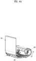
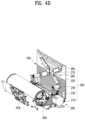
- FIGS. 4A to 4D are a front perspective view and a rear perspective view showing the inside of the display device 1000.
- FIGS. 4A to 4D show a state of the display device 1000 except for a bracket (or frame), a screw, a clip, a rod (or bar), etc. for fixing a bottom fixing frame 530 and other parts in FIGS. 3A and 3B .
- each diagram may represent a flexible display device for a vehicle according to embodiments of the present invention.
- the display device 1000 may include a casing having an opening, a display part 100 to be retracted or extended into or out of the casing through the opening, a display driver 200 for moving the display part 100, a guide part 300 for guiding the display part 100, and a display winder 400 for winding the display part 100.
- the casing may include the side casing 10 and the upper casing 20, and the side casing 10 and the upper casing 20 may be assembled together.
- the casing may include an inner space, and thus other components may be placed in the inner space of the casing.
- the casing may include an opening, and the opening may be formed in a size for the display part 100 to be retracted or extended (hereinafter referred to as 'retracted or extended') into or out of the casing.
- the casing may protect the components located in the inner space and improve the appearance of the device.
- the shape of the casing is not limited to that shown in the drawings, and one of ordinary skill in the art to which the present invention pertains (hereinafter referred to as 'one of ordinary skill in the art') may appropriately change within the scope of the present claims.
- the display part 100 may include components related to a display screen displaying various vehicle-related information.
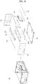
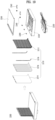
- the display part 100 may include a display 110, a connecting sheet 120, and a display cover 130.
- FIG. 5 is an exploded view of the display part 100 of the display device 1000, and shows components of the display part 100.
- the display 110 may be a flexible or rollable display 110.
- the display 110 may be a plastic organic light-emitting diode (POLED).
- POLED is an OLED applied with a polyimide (PI) substrate, a type of plastic, and may be implemented with a curved surface.
- PI polyimide
- the display 110 may be bent, and a curvature radius at which the display 110 is bent may be at least 50 mm or more. In detail, the radius of curvature of the display 110 may be at least 30 mm or more.
- the display 110 may include a light emitting diode (LED), an OLED, an AMOLED, and a PMOLED.
- the width and height of the display 110 may be appropriately designed by one of ordinary skill in the art.
- the connecting sheet 120 may have one side connected to a lower end of the display 110 and the other side connected to the display winder 400.
- the connecting sheet 120 may be flexible and may be wound or unwound through the display winder 400.
- One side of the connecting sheet 120 may be attached to the display 110 using a double-sided tape.
- the connecting sheet 120 may include a sheet formed of a PET material. The material of the connecting sheet 120 may be appropriately selected by one of ordinary skill in the art in consideration of flexibility.
- the display 110 and the connecting sheet 120 may be connected, and the connecting sheet 120 may be wound or unwound by the display winder 400. Therefore, when the display 110 is retracted into a casing, the display winder 400 may wind the connecting sheet 120, and when the display 110 is extended out of the casing, the display winder 400 may unwind the connecting sheet 120.
- the display cover 130 may be a cover protecting rear surfaces of the display 110 and the connecting sheet 120.
- the display cover 130 may supplement the display 110 and the connecting sheet 120, which do not have rigidity.
- the display cover 130 may include a plurality of covers that are long in a horizontal direction and short in a vertical direction.
- the plurality of covers may be adhered to the rear surface of the display 110 or the rear surface of the connecting sheet 120 through a double-sided adhesive 140.
- the double-sided adhesive 140 may include a double-sided tape such as a FOAM tape.
- the double-sided adhesive 140 may be separately applied to the plurality of covers of the display cover 130.
- the widths of the plurality of covers of the display cover 130 may be greater than or equal to the width of the display 110.
- the heights of the plurality of covers may be appropriately designed by one of ordinary skill in the art in consideration of whether to flexibly respond to bending of the display 110.
- the display cover 130 may further include a magnetism part 160 at both ends in a horizontal direction.
- the magnetism part 160 may utilize a magnetic force for attachment to and detachment from a rear protection cover 2210 (refer to FIG. 18 ) to be described later.
- a rear protection cover 2210 (refer to FIG. 18 )
- an externally exposed portion of the display part 100 may be protected by attaching the rear protection cover 2210 (refer to FIG. 18 ), and an inner portion of the casing of the display part 100 may be separated from the rear protection cover 2210 (refer to FIG. 18 ).
- the display part 100 may further include an upper fixing plate 150, a top fixing clip 152, and a connection reinforcing part 170.
- the upper fixing plate 150 may be a flat plate in surface contact with a part of an upper end of the rear surface of the display 110.
- a width of the upper fixing plate 150 may be at least equal to or greater than a width of the display 110.
- the top fixing clip 152 may be connected to the upper fixing plate 150 at an upper end of a front surface of the display 110.
- An upper end of the display 110 may be fixed by connecting the top fixing clip 152 and the upper fixing plate 150.
- the upper fixing plate 150 and the top fixing clip 152 may protect the upper end of the flexible display 110, and the upper fixing plate 150 may be connected to the display driver 200 to be described later to receive power of a motor.
- the upper fixing plate 150 and the top fixing clip 152 may improve the appearance of the display device.
- the material of the upper fixing plate 150 and the top fixing clip 152 includes aluminum (AL), and other materials having appropriate rigidity may be applied thereto by one of ordinary skill in the art.
- connection reinforcing part 170 is a component for overcoming the vulnerability of a connection part between the display 110 and an sPCB.
- FIG. 6 is an enlarged view of a lower connection portion of the display 110 to explain the connection reinforcing part 170.
- the display 110 may be connected to a sPCB through a flexible flat cable (FFC), and the FFC may be damaged by an external force when the display 110 is moved. Therefore, the connection reinforcing part 170 may protect the FFC by fixing the FFC on front and rear surfaces of the display 110 or the connecting sheet 120.
- the connection reinforcing part 170 two members having a length in a horizontal direction may be coupled to each other at the front and rear surfaces of the display 110 with the display 110 therebetween. By coupling the two members, the FFC may be fixed, and may be maintained in a shape that is not subjected to an external force. Coupling of the two members may be performed through a double-sided tape or screw fastening.
- the display 110 may be connected to an sPCB and a cPCB, and final control may be performed by a main PCB.
- the display driver 200 is a component moving the display part 100.
- FIG. 7 is an exploded view of the display driver 200.
- the configuration of the display driver 200 may be referred to FIGS. 4C and 4D .
- the display driver 200 may include a motor 210 connected to the inside of a casing, a worm gear part 230 connected to the motor 210, a worm wheel part 240 connected to the worm gear part 230, a first driving arm 250 connected to the worm wheel part 240, and a second driving arm 270 connected to the first driving arm 250.
- Rotation of the motor 210 may be controlled by a controller (not shown). For example, an operation of the motor 210 may be controlled to appropriately retract or extend the display part 100.
- the display part 100 may have different levels of exposure extended to the outside of the casing depending on an exposure mode, and the motor 210 may adjust an exposure range of the display part 100 by controlling an operation according to an exposure mode selected by a user.
- the motor 210 may be a stepping or hybrid motor.
- the worm gear part 230 may include a rod rotating on a rotation shaft parallel to the motor 210 and a worm gear connected to the rod.
- the worm gear part 230 may rotate by rotation of the motor 210, and may be connected to the motor 210 through a timing belt 220 and may operate.
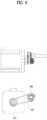
- FIG. 9 illustrates a connection portion of the motor 210 of the display driver 200.
- the motor 210 may rotate the rod of the worm gear part 230 using the timing belt 220.
- the worm wheel part 240 may be connected to the worm gear part 230 and include a worm wheel gear having a rotation shaft perpendicular to the rotation shaft of the motor 210 or the worm gear part 230. As shown in FIG. 4C , since a rotation shaft of the motor 210 is horizontal to the left and right of the display device 1000, a rotation shaft of the worm wheel part 240 may be perpendicular to an exposed surface of the display 110. The worm wheel part 240 may rotate on a virtual plane parallel to the plane of the display 110 by rotation of the motor 210.
- the first driving arm 250 may have one end connected to the worm wheel part 240 and pivot according to rotation of the worm wheel part 240.
- the first driving arm 250 may be an arm member having a predetermined length and may pivot on a virtual plane parallel to an exposed surface of the display part 100.
- the first driving arm 250 may be located adjacent to a rear surface of the display part 100.
- One end of the second driving arm 270 may be pivotably connected to the other end of the first driving arm 250, and the other end of the second driving arm 270 may be pivotably connected to an upper end of the display part 100.
- the first driving arm 250 and the second driving arm 270 may be connected in the form of meshing teeth as shown in the drawing.
- a connecting portion of the first driving arm 250 and the second driving arm 270 may be connected to a gear (e.g., a spur gear), and thus when the first driving arm 250 pivots, the second driving arm 270 may also pivot. Accordingly, the second driving arm 270 may pivot according to rotation of the worm wheel part 240.
- the second driving arm 270 may be an arm member having a predetermined length and may pivot on a virtual plane parallel to an exposed surface of the display part 100. That is, the second driving arm 270 may pivot on the same plane as a pivoting plane of the first driving arm 250. However, the second driving arm 270 may pivot in a direction opposite to that of the first driving arm 250. For example, when the first driving arm 250 pivots clockwise, the second driving arm 270 may pivot counterclockwise.
- the second driving arm 270 may be positioned adjacent to the rear surface of the display part 100, and movement of the second driving arm 270 may be guided by a guide provided in the upper fixing plate 150.
- the upper fixing plate 150 may have a groove for guiding the second driving arm 270.
- the upper fixing plate 150 may include a groove for guiding the first driving arm 250.
- the display driver 200 may further include an arm joint 260 for fixing a connection state between the first driving arm 250 and the second driving arm 270.
- the arm joint 260 may ensure that cogwheels of the first drive arm 250 and cogwheels of the second drive arm 270 are well engaged but connection therebetween is not released.
- a joint spacer 262 may be added to a connection portion between the first driving arm 250, the second driving arm 270, and the arm joint 260 to remove a gap formed by an assembly step.
- the joint spacer 262 may be positioned in an interval between the first driving arm 250 and the arm joint 260 and between the second driving arm 270 and the arm joint 260, and thus the aforementioned gap may be removed.
- the joint spacer 262 may minimize a front-back tilt of the display part 100 that may occur in a situation in which the display part 100 is extended to the maximum.
- the worm wheel part 240, the first driver 250, and the second driver 270 may be provided symmetrically left and right with respect to the center of the display part 100. That is, the display driver 200 may include a pair of first driving parts 250 that are left and right symmetric, a pair of second driving parts 270 that are left and right symmetric, and a pair of the worm wheel parts 240 that are left and right symmetric.
- rotation directions of the pair of first drivers 250 are opposite to each other, and rotation directions of the pair of second drivers 270 are opposite to each other.
- the other ends of the pair of second drivers 270 may be rotatably connected to the upper end of the display part 100, and the upper arm joint 280 for connecting the second driver 270 to the upper end of the display part 100 may be provided.
- the upper arm joint 280 may have a predetermined length in a horizontal direction, and both ends thereof may be rotatably connected to the other ends of the pair of second drivers 270, respectively.
- the upper arm joint 280 may be connected to an upper end of the upper fixing plate 150 of the display part 100.
- the first driver 250 and the second driver 270 may include a metal material and may be formed of aluminum (AL).
- Materials of the arm joint 260 and the upper arm joint 280 may include steel electrolytic cold commercial (SECC) or SUM specified in the Korean Industrial Standards (KS).
- SECC steel electrolytic cold commercial
- KS Korean Industrial Standards
- a material of the joint spacer 262 may include PET.
- a material of the worm wheel gear may include Polyoxymethylene (POM), and a material of the worm gear may include brass.
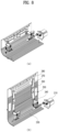
- FIG. 8 is a diagram to explain an operation process of the display driver 200 of the display device 1000.
- FIG. 8A shows the display driver 200 in a state in which the display part 100 is not exposed
- FIG. 8B shows the display driver 200 in a state in which the display part 100 is exposed to the maximum.
- rotation of the motor 210 may cause the worm gear part 230 to rotate.
- the pair of the worm wheel part 240 may rotate clockwise and counterclockwise, respectively.
- the pair of first driving parts 250 each rotate in the same direction as the pair of the worm wheel parts 240. Therefore, the other end (connection portion with the second driver) of the first driver 250 gradually rises upward, and the second driver 270 connected to the first driver 250 rotates in an opposite direction to a direction of rotation of the first driver 250.
- the other end (a connection portion of the upper arm joint 280) of the second driver 270 is rotatably connected to a point at an upper end of a rear surface of the display part 100. Accordingly, the second driver 270 may raise the display part 100.
- a process of retracting the display part 100 from FIG. 8B to FIG. 8A may be performed by rotating the motor 210 in an opposite direction to the above description.
- FIG. 10 is an exploded view of the guide part 300 of the display device 1000, and FIG. 11 shows arrangement of the guide part 300.
- the guide part 300 is connected to the inside of a casing and is a component that guides movement of the display part 100.
- the guide part 300 may guide the display part 100 to have a path along which the display part 100 moves and which has a curvature radius in a range of 30 mm to 70 mm.
- the guide part 300 may guide the display part 100 to have a path along which the display part 100 moves and which has a curvature radius R in a range of 45 mm to 55 mm.
- the display part 100 may be bent according to the curvature radius guided by the guide part 300 as being retracted or extended into or out of the casing.
- the guide part 300 may include a curvature guide for guiding a movement path in which a curvature radius is formed, and the curvature guide may include a front curvature guide 310 in contact with a front surface of the display part 100, and a rear curvature guide 320 in contact with a rear surface of the display part 100.
- the front curvature guide 310 and the rear curvature guide 320 may include a plurality of rollers. The size and shape of the roller may be appropriately selected by one of ordinary skill in the art.
- the curvature guide of the guide part 300 may include a plurality of rollers connected to a guide fixing bar 312 disposed in left and right directions in an inner space of the casing, or may include a plurality of rollers fixed to various frames or brackets of the part fixing part 500 (refer to FIG. 15 ) inside the casing
- the guide part 300 may further include a first straight guide 330 and a second straight guide 340 that guide the display part 100 in a vertical or horizontal direction.
- the first straight guide 330 guides the display part 100 in a vertical direction
- the second straight guide 340 guides the display part 100 in a horizontal direction.
- a material of the plurality of rollers may include rubber or polyoxymethylene (POM).
- a material of the frame or bracket for fixing the rollers may include steel electrolytic cold commercial (SECC) or SUM specified in the Korean Industrial Standards (KS).
- the guide part 300 may also function as a guide in a manner different from that shown in the drawings.
- One of ordinary skill in the art may apply a known guide method, and the guide part 300 of the present specification may include a known guide method.
- FIG. 12A is an exploded view of the display winder 400 of the display device 1000.
- the display winder 400 is a component for winding the display part 100 according to retraction and extension of the display part 100.
- the display winder 400 includes a rotary drum 410 and a sensor recognizer 470 for detecting a rotation state of the rotary drum 410.
- the rotary drum 410 rotates around a drum shaft 420 installed in left and right horizontal directions inside a casing as a center shaft.
- the rotary drum 410 may have a cylindrical shape, and the display part 100 may be wound or unwound again on an outer circumferential surface of the cylindrical shape.
- the rotary drum 410 may include a rotary spring 450.
- the rotary spring 450 applies an elastic force for the rotary drum 410 to rotate in a direction in which the display part 100 is wound. Therefore, the display part 100 may be pulled downward by the rotary spring 450, and a display screen may be maintained flatter than before by the force.
- the rotary drum 410 may further include a spring case 460, a cap 440, and a holder 430.
- the spring case 460 may be a case having an inner space for accommodating the rotary spring 450
- the cap 440 may be a component for closing the opening of the spring case 460 in which the rotary spring 450 is accommodated.
- the holder 430 may be a component that fixes the positions of the components (spring case and cap) related to the rotary spring 450.
- the sensor recognizer 470 detects a rotation state of the rotary drum 410.
- the sensor recognizer 470 may include a plurality of sensors 472 and a detection part 474 sensed by the plurality of sensors.
- the detection part 474 may rotate with the rotary drum 410 and may be detected by at least one sensor among the plurality of sensors 472.
- Sensing states of the plurality of sensors 472 may be different according to a rotation state of the rotary drum 410, and an operation of the motor 210 may be controlled based on the sensing state of the plurality of sensors 472. In other words, based on the rotation state of the rotary drum 410, one of the plurality of sensors 472 may recognize a state different from the other sensors, and the operation of the motor 210 may be controlled accordingly.
- a material of the rotary drum 410 may include acrylonitrile butadiene styrene (ABS), a material of the spring case 460, the cap 440, and the holder 430 may include polyoxymethylene (POM), and a material of the rotary spring 450 may include SUS.
- a material of a bracket related to the display winder 400 may include steel electrolytic cold commercial (SECC).
- FIG. 12B shows the inside of a display device from the side.
- R2 denotes a radius of a cross section of the rotary drum 410 having a circular cross section
- R1 denotes a radius of curvature at which the display part 100 is bent.
- the radius R2 of the cross section of the rotary drum 410 may be at least equal to or larger than R1.
- FIG. 12C shows components related to the rotary spring 450 of the display device.
- FIG. 12C shows the case in which the rotary drum 410, the spring case 460, the rotary spring 450, and the holder 430 are coupled
- FIG. 12C is an enlarged view of the rotary spring 450.
- the spring case 460 is fixed to a left or right end of the rotary drum 410, and the rotary spring 450 is accommodated in an accommodation space inside the spring case 460.
- the holder 430 is located in a central portion of the accommodation space of the spring case 460 to maintain a constant state irrespective of rotation of the rotary drum 410.
- the rotary spring 450 is formed of of an elastic object having a spiral shape, and the rotary spring 450 may include a first fixing hook 452 on the outside of the spiral shape and a second fixing hook 454 on a central portion of the spiral shape.
- the first fixing hook 452 of the rotary spring 450 is connected to a groove formed inside the spring case 460, and the second fixing hook 454 of the rotary spring 450 is connected to a groove formed in the holder 430.
- the spring case 460 also rotates, and as the spring case 460 rotates, the position of the first fixing hook 452 changes.
- the second fixing hook 454 is connected to the holder 430 in a constant state, the position of the fixing hook 452 does not change.
- the elastic force of the rotary spring 450 acts in a direction in which the rotary drum 410 winds the display part 100.
- FIG. 12D shows a direction of the elastic force acting on the rotary drum 410 of the display device.
- a rotation direction of the rotary drum 410 is indicated by a solid arrow, and a direction in which an elastic force of the rotary spring 450 acts is indicated by a dotted arrow.
- the elastic force of the rotary spring 450 acts in a direction in which the display part 100 is pulled.
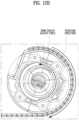
- FIG. 13A is a diagram for explaining control of exposure of a display according to rotation of the display winder 400.
- FIG. 13B illustrates a principle by which the sensors 472 recognize the detection part 474.
- the plurality of sensors 472 is fixed at a position in which rotation of the rotary drum 410 is to be sensed.
- the plurality of sensors 472 may be connected to an inner surface of a casing positioned adjacent to the rotary drum 410 or other places such as a bracket having a fixed position. That is, the sensors 472 may not rotate with the rotary drum 410, but may detect a rotation state of the rotary drum 410 at a certain position.
- the detection part 474 is connected to the rotary drum 410 and rotates therewith when the rotary drum 410 rotates.
- the detection part 474 may have an appropriate shape for any one of the plurality of sensors 472 and the remaining sensors to detect different states. Accordingly, the detection part 474 may have various shapes depending on installation positions of the plurality of sensors 472.
- the shape of the detection part 474 may be provided such that when the first sensor recognizes the detection part 474 (on), the second sensor to the fourth sensor do not recognize the detection part 474 (off).
- the shape of the detection part 474 may be provided such that if the first sensor does not recognize the detection part 474 (off), the remaining sensors (the second to fourth sensors) recognize the detection part 474 (on).
- the detection part 474 has a shape protruding from an end of the rotary drum 410 to pass through an area in which each of the sensors 472 recognizes (on or off) according to rotation of the rotary drum 410.
- the area recognized by the sensors 472 may indicate an area in which the sensors 472 are capable of recognizing the detection part 474.
- the sensors 472 may include a photosensor, and the detection part 474 may include a hole 476.
- the hole 476 may be a hole formed in the detection part 472, and the sensors 472 may differently sense the hole 476 and the remaining part of the detection part 472.
- the remaining part of the detection part 472 blocks a space between a light emitting part and a light receiving part of the sensors 472 (refer to (b) of FIG. 13B ), whereas the hole 476 of the detection part 472 opens the space between the light emitting part and the light receiving part of the sensors 472 (refer to (c) of FIG. 13B ), and thus the sensors 472 may detect the hole 476 differently from the remaining part.
- a display device may have a configuration other than a hole such as the hole 476 depending on a type of sensor.
- the detection part 474 rotates, and the position of the hole 476 formed in the detection part 474 may be changed.
- the rotary drum 410 rotates by a predetermined angle and the position of the hole 476 is in a recognition area of any one of the sensors 472, the corresponding sensor may recognize the hole 476.
- a degree by which the rotary drum 410 rotates may be recognized.
- an exposure range of the display part 100 may be controlled.
- a first mode is a state in which the display part 100 is retracted and the rotary drum 410 winds the display part 100 to the maximum.
- an exposure mode of the display part 100 is the first mode. It may be seen that when the rotary drum 410 rotates and the hole 476 is located in a recognition region of a second sensor 472b, the exposure mode of the display part 100 is a second mode. Similarly, a third mode and a fourth mode may also be distinguished depending on which sensor with a recognition region in which the hole 476 is located.
- the display driver 200 may drive the motor 210 to extend the display part 100 and the rotary drum 410 rotates accordingly.
- the plurality of sensors 472 may recognize that the second mode is entered.
- sensing states (on or off) of the second sensor 472b corresponding to the second mode and the remaining sensors among the plurality of sensors 472 may become different.
- the second sensor 472b may be in an on state, and the remaining sensors may be in an off state.
- the display device 1000 may be recognized to become in the second mode state and an operation of the motor 210 may be stopped.
- the display driver 200 may drive the motor 210 to further extend the display part 100, and when the sensor recognizer 470 recognizes that the third mode is entered, driving of the motor 210 may be stopped.
- the display device 1000 may differently control a degree of exposure of the display part 100 according to various modes.
- An exposure mode of the display part 100 may be divided into four modes including the first mode in which the display part 100 is completely retracted into the casing and the fourth mode in which the display part 100 is completely extended out of the casing.
- Each mode may be classified according to a type and function of information displayed on the display 110.
- the third mode may be used on a navigation screen, and the fourth mode may be used when a video or game is played.
- An exposure mode of the display device 1000 may be classified into more types of modes according to an exposure range, and the number of the sensors 472 may be one or more.
- FIG. 13C shows the detection part 474 and the hole 476 according to another embodiment.
- the detection part 474 may include a plurality of holes 476 arranged at a predetermined interval.
- the plurality of holes 476 may pass through the recognition region of the sensor 472 while the rotary drum 410 rotates, and the sensor 472 may detect the number of holes 476 passing through the recognition region. That is, the sensor 472 may detect the number of the holes 476 passing through the recognition region. Accordingly, a rotation angle of the rotary drum 410 may be calculated based on the number of holes 476 detected by the sensor 472.
- the sensor recognizer 470 may include one sensor 472, and the detection part 474 may include the plurality of holes 476 arranged at a predetermined interval.
- the number and interval of the plurality of holes 476 may be appropriately determined by one of ordinary skill in the art.
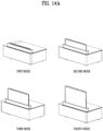
- FIG. 14A shows a degree by which the display part 100 is extended according to a first mode to a fourth mode.
- the first mode may represent a state in which the display part 100 is completely accommodated inside a casing
- the fourth mode may represent a state in which the display part 100 is extended out of the casing to the maximum.
- the second mode and the third mode may be distinguished according to an extension degree of the display part 100.
- the number of modes of the display part 100 may be variously set as needed.
- FIG. 14B shows a method of controlling the display device 1000 (hereinafter referred to as a "control method") according to an embodiment of the present invention.
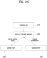
- FIG. 14C shows components of a vehicle for performing the control method.
- the components of the vehicle shown in FIG. 14C may be configured by hardware, software, or a combination thereof, and the components may not be clearly physically separated, but conceptually separated according to a function to be performed.
- the control method includes selecting a display mode (S1410), transmitting display mode information in a head unit (or controller) (S1420), and/or controlling a display in a display module (S1430).
- a specific exposure mode of a display is selected as a user manipulates an interface of a vehicle.
- the user may select a navigation mode, a movie mode, a general mode, or the like through the interface of the vehicle as needed.
- a display mode corresponding to each mode may be selected according to user selection. For example, when the user selects and activates a navigation function, the third mode may be selected as a display mode related to a navigation device.
- a controller 610 may be a component for processing/calculating data to control the vehicle and may be referred to as a head unit generally.
- the display control module 620 controls movement of the display part 100 based on information on an input display mode.
- the controlling the display (S1430) may include transmitting a signal to the motor 210 (S1432), moving the display part 100 by pivoting the first driving arm 250 or the second driving arm 270 by the motor 210 (S1434), and/or checking movement of the display part 100 by the sensors 472 (S1435).
- the transmitting the signal to the motor 210 (S1432) and the moving the display part 100 by pivoting the first driving arm 250 or the second driving arm 270 by the motor 210 (S1434) indicates that the display driver 200 operates and moves the display part 100.
- the motor 210 rotates by receiving a signal corresponding to display mode information. According to rotational driving of the motor 210, the worm gear part 230 and the worm wheel part 240 connected to the motor 210 operate, and accordingly, the first driving arm 250 and/or the second driving arm 270 may operate to retract or extend the display part 100.
- the sensors 472 may detect a rotation state of the rotary drum 410 to check whether the display part 100 moves according to input mode information.
- the motor 210 stops an operation thereof.
- FIG. 14D is a flowchart of an example of control of an exposure mode of a display.
- the control method shown in FIG. 14D may be performed by the display control module 620 of FIG. 14C .
- the control method may include comparing an input mode and a current mode (S1442), rotating a motor in a first direction or a second direction in response to the comparison result (S1444), checking whether the display part 100 moves according to the input mode by the sensor part 630 (S1446), and stopping driving of the motor in response to the checking result (S1448).
- the current mode and the input mode of the display part 100 may be compared with each other. For example, when the current mode is a first mode and the input mode is a second mode, the first mode and the second mode may be compared with each other. Accordingly, the display control module 620 may determine a direction in which the motor 210 is to be driven in order to move the display part 100 in the input mode.
- Mode information corresponding to specific values in respective modes may be compared with each other. For example, when the first mode as the current mode corresponds to 1 and the second mode as the input mode corresponds to 2, the value corresponding to the input mode may be determined to be greater than the value corresponding to the current mode.
- the motor In the rotating the motor in the first direction or the second direction in response to the comparison result (S1444), when a value corresponding to the input mode is greater than a value of the current mode, the motor may rotate in the first direction. When a value corresponding to the input mode is smaller than a value corresponding to the current mode, the motor may rotate in the second direction.
- a value of the input mode is greater than a value of the current mode, and thus the motor 210 may rotate in the first direction to extend the display part 100.
- a value of the input mode is smaller than a value of the current mode, and thus the motor 210 may rotate in the second direction to retract the display part 100.
- the sensor part 630 checks a rotation state based on the contents described in FIGS. 13A to 13C .
- the sensor part 630 may check whether the rotary drum 410 rotates according to the input mode based on information detected by the sensors 472.
- the motor 210 continues to drive.
- the display control module 620 may continue to rotate the motor because the input mode, the fourth mode, is not reached.
- the current mode and the input mode may be compared with each other and the motor 210 may be rotated in an opposite direction to a previous one.
- the current state recognized by the sensor part 630 and the input mode may be compared with each other and the motor 210 may be rotated in a display retraction direction.
- FIGS. 14E and 14F show movement states of the first driving arm 250 and the second driving arm 270 for each exposure mode.
- a portion marked with a dotted line in the second mode to the fourth mode represents an initial state (first mode).
- FIG. 15 is an exploded view of a component fixing part 500 of the display device 1000.
- the component fixing part 500 is located inside a casing and includes a frame, a rod, etc. for fixing the aforementioned components to a specific location or maintaining a shape of a case.
- the component fixing part 500 may include an interval adjustment rod 510, the side fixing frame 520, the bottom fixing frame 530, a first driver support frame 540, a second driver support frame 542, and a PCB support frame 550.
- the component fixing part 500 may fix a cPCB and a main PCB to the frame.
- the interval adjustment rod 510 is a rod arranged horizontally to the left and right inside the casing.
- the interval adjustment rod 510 may be plural, and may be provided at an appropriate position to fix shapes of the frames.
- the side fixing frame 520 is a flat frame positioned adjacent to a left or right surface inside the casing
- the bottom fixing frame 530 is a flat frame positioned adjacent to a lower surface inside the casing.
- the first driver support frame 540 and the second driver support frame 542 are frame components for supporting or fixing components corresponding to the display driver 200.
- the PCB support frame 550 is a frame component for fixing a PCB.
- a material of the component fixing part 500 may include steel electrolytic cold commercial (SECC) or SUS.
- FIGS. 16 to 20 are diagrams for explaining a display device 2000 according to another embodiment of the present invention.
- FIG. 16 is a front perspective view of the display device 2000
- FIG. 17 is a rear perspective view of the display device 2000 in a state in which an upper cover is removed.
- FIG. 18 is a rear perspective view of the inside of a casing of the display device 2000.
- the display device 2000 according to another embodiment of the present invention is different from the display device 1000 in that the display device 2000 further includes a rear cover part 2200.
- the same components as those of the aforementioned display device 1000 will be described using the same reference numerals.
- the rear cover part 2200 may cover a rear surface of the display part 100 and the display driver 200 (a first driving arm or a second driving arm) exposed to the outside to protect the components and improve the appearance of the device.
- FIG. 19 is an exploded view of the rear cover part 2200 of the display device 2000.
- the rear cover part 2200 may include the rear protection cover 2210, an upper cover guide part 2220, and a lower cover guide part 2230.
- the rear protection cover 2210 is attachable to or detachable from a rear surface of the display part 100 and covers an exposed rear surface of the display part 100.
- the rear protection cover 2210 may include a rear detachable cover 2212, a magnetism part 2216, a double-sided adhesive 2218, and a cover reinforcement sheet 2214.
- the rear detachable cover 2212 is a cover that protects a rear surface of the display part 100 or an exposed portion of the display driver 200.
- the rear detachable cover 2212 may include a plurality of covers that are long in a horizontal direction and short in a vertical direction.
- the plurality of covers may be attached to one surface of the cover reinforcement sheet 2214 through the double-sided adhesive 2218.
- the double-sided adhesive 2218 may include a double-sided tape such as a FOAM tape. Widths of the plurality of covers included in the rear detachable cover 2212 may be less than or equal to the width of the display part 100.
- the heights of the plurality of covers may be appropriately designed by one of ordinary skill in the art to a height for flexibly responding to bending.
- the rear detachable cover 2212 may further include the magnetism part 2216 at both ends in a horizontal direction.
- the magnetism part 2216 includes a magnet to attach to and detach from the display part 100.
- the display cover 130 of the display part 100 may be provided with the magnetism part 160 at both left and right ends, and the magnetism part 160 of the display cover 130 and the magnetism part 2216 of the rear detachable cover 2212 may be attached to or detached from each other by magnets.
- the display cover 130 of the display part 100 and the rear protection cover 2210 may have a plurality of magnets arranged in a vertical direction (or a retraction or extension direction of the display part) at positions corresponding to each other.
- the rear protection cover 2210 is separated from the display part 100 when the display part 100 is retracted into the casing, and magnetically attached to the exposed portion of the display part 100 when the display part 100 is extended out of the casing.
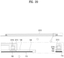
- FIG. 20 shows a cross section of a connection portion of the rear protection cover 2210 and the display part 100 in detail.
- the magnetism part 2216 is provided at both left and right ends of the rear detachable cover 2212, and a position of the magnetism part 2216 corresponds to the position of the magnetism part 160 provided in the display cover 130.
- the upper cover guide part 2220 and the lower cover guide part 2230 may guide the rear protection cover 2210 separated from the display part 100.
- the upper cover guide part 2220 comes into contact with an outer surface of the rear protection cover 2210 to guide the rear protection cover 2210
- the lower cover guide part 2230 comes into contact with an inner surface of the rear protection cover 2210 to guide the rear protection cover 2210. That is, movement of the separated rear protection cover 2210 is guided along a space between the upper cover guide part 2220 and the lower cover guide part 2230.
- the display device 2000 may have an inner space for built therein the rear protection cover 2210 at the top, and the rear protection cover 2210 may be extended out of a casing or may be retracted into the casing. and the rear protection cover 2210 may be extended out of the casing or retracted into the casing.
- the upper cover guide part 2220 and the lower cover guide part 2230 may have a flat plate shape including a curved surface.
- the rear protection cover 2210 may be guided along a curved surface between a lower surface of the upper cover guide part 2220 and an upper surface of the lower cover guide part 2230.
- the rear cover part 2200 may further include a cover guide roller 2240 fixed to the inside of the casing to guide the rear protection cover 2210 and a bracket 2242 supporting the cover guide roller 2240.
- the casing of the rear cover part 2200 may further include an upper cover 2250 and a cover fixture 2260 for fixing the upper cover 2250.
- a material of the rear detachable cover 2212 may include polycarbonate (PC) or aluminum.
- a material of the cover reinforcement sheet 2214 may include polyethylene terephthalate (PET).
- Materials of the upper cover guide part 2220, the lower cover guide part 2230, and the upper cover 2250 may include acrylonitrile butadiene styrene (ABS).
- a material of the cover guide roller 2240 may include rubber, and a material of the bracket 2242 may include steel electrolytic cold commercial (SECC).
- the rear cover part 2200 may have a structure to be disassembled or assembled in the display device 2000, and whether or not to apply the rear cover part 2200 may be selected according to user preference or a vehicle environment.
- a volume of the device required for storing the display may be reduced.
- an exposure range of the display may be controlled by a sensor recognition method appropriately applied to the method of winding the display, and the effectiveness of the display device may be improved. By controlling the exposure range of the display, only an exposed area may be displayed, and power consumption due to use of the display may be reduced.
- the display device may be applied to various positions such as a center, a passenger display, a center console display, a rear seat entertainment display, a rear center display, or a rear control display of a vehicle.
- the usability of an inner space of a vehicle may be increased by reducing the size of an accommodation space for a display.
- the usability of the display may be increased by adjusting a degree of exposure of the display, and power may be saved by using only the exposed portion of a display area.
- a flexible display may be retracted or extended into or out of an accommodation space while being safely protected.
Landscapes
- Engineering & Computer Science (AREA)
- Mechanical Engineering (AREA)
- Chemical & Material Sciences (AREA)
- Combustion & Propulsion (AREA)
- Transportation (AREA)
- Physics & Mathematics (AREA)
- General Physics & Mathematics (AREA)
- Theoretical Computer Science (AREA)
- Optics & Photonics (AREA)
- Microelectronics & Electronic Packaging (AREA)
- Devices For Indicating Variable Information By Combining Individual Elements (AREA)
- Fittings On The Vehicle Exterior For Carrying Loads, And Devices For Holding Or Mounting Articles (AREA)
Claims (13)
- Flexible Anzeigevorrichtung (1000) für ein Fahrzeug, umfassend:ein Gehäuse mit einer Öffnung;ein Anzeigeteil (100), das so eingerichtet ist, dass es durch die Öffnung in das Gehäuse eingefahren oder daraus ausgefahren werden kann;einen Anzeigetreiber (200), der so eingerichtet ist, dass er das Anzeigeteil (100) bewegt; undeinen Anzeigewickler (400), der so eingerichtet ist, dass er das Anzeigeteil (100) basierend auf einer Bewegung des Anzeigeteils (100) aufwickelt,wobei das Anzeigeteil (100) so eingerichtet ist, dass es basierend auf einer Mehrzahl von Modi mit unterschiedlichen Ausfahrbereichen ausgefahren wird,wobei der Anzeigewickler (400) eine Drehtrommel (410) mit einer Außenumfangsfläche, auf die das Anzeigeteil (100) aufgezogen werden kann, und einen Sensorerkenner (470) umfasst, der so eingerichtet ist, dass er einen Drehzustand der Drehtrommel (410) erkennt,wobei:der Anzeigetreiber (200) einen Motor (210) umfasst, der mit dem Gehäuse verbunden ist; undder Anzeigetreiber (200) so eingerichtet ist, dass er das Anzeigeteil (100) basierend auf dem Drehzustand der Drehtrommel (410) bewegt, der vom Sensorerkenner (470) erkannt wird,dadurch gekennzeichnet, dassder Anzeigetreiber (200) weiterhin einen Antriebsarm (250, 270) umfasst, der den Motor (210) und das Anzeigeteil (100) verbindet.
- Flexible Anzeigevorrichtung (1000) nach Anspruch 1, wobei:
der Sensorerkenner (470) umfasst:eine Mehrzahl von Sensoren (472), die innerhalb des Gehäuses angeordnet sind; undein Erkennungsteil (474), das mit der Drehtrommel (410) verbunden ist und von der Mehrzahl von Sensoren (472) erkannt wird; unddas Erkennungsteil (474) eine Form hat, damit jeder der Mehrzahl von Sensoren (472) einen anderen Zustand als verbleibende Sensoren entsprechend dem Drehzustand der Drehtrommel (410) erkennen kann. - Flexible Anzeigevorrichtung (1000) nach Anspruch 2, wobei:die Mehrzahl von Sensoren (472) einen Fotosensor umfasst;das Erkennungsteil (474) ein Loch umfasst unddas Loch in einem Erkennungsbereich eines beliebigen der Mehrzahl von Sensoren (472) entsprechend dem Drehzustand der Drehtrommel (410) angeordnet ist.
- Flexible Anzeigevorrichtung (1000) nach Anspruch 1, wobei:
der Sensorerkenner (470) umfasst:einen Sensor (472), der innerhalb des Gehäuses angeordnet ist; undein Erkennungsteil (474), das mit der Drehtrommel (410) verbunden ist und entsprechend einer Drehung des Sensors (472) durch einen Erkennungsbereich des Sensors (472) verläuft;der Erkennungsteil (474) eine Mehrzahl von Löchern (476) umfasst, die in einem vorgegebenen Abstand angeordnet sind; undder Sensor (472) die Anzahl der Mehrzahl von Löchern (476) erkennt, die durch den Erkennungsbereich verlaufen. - Flexible Anzeigevorrichtung (1000) nach einem der Ansprüche 3 und 4, weiterhin umfassend:ein Anzeigesteuermodul (620), das so eingerichtet ist, dass es ein Signal entsprechend einer Eingabe eines Benutzers empfängt und den Anzeigetreiber (200) steuert,wobei die Drehtrommel (410) eine Drehfeder (450) umfasst unddie Drehfeder (450) so eingerichtet ist, dass sie eine elastische Kraft in eine Richtung ausübt, in die das Anzeigeteil (100) aufgewickelt ist.
- Verfahren zum Steuern der Anzeigevorrichtung (1000) nach Anspruch 5, wobei das Verfahren umfasst:Auswählen eines Anzeigemodus;Senden von Informationen über den ausgewählten Anzeigemodus an das Anzeigesteuermodul (620) undSteuern einer Anzeige durch das Anzeigesteuermodul (620),wobei das Steuern der Anzeige umfasst:Senden eines Signals entsprechend Informationen über den ausgewählten Anzeigemodus an einen Motor (210);Drehen des Motors (210), um das Anzeigeteil (100) zu bewegen; undÜberprüfen einer Bewegung des Anzeigeteils (100).
- Verfahren nach Anspruch 6, wobei:das Senden des Signals ein Senden unterschiedlicher Signale als Reaktion auf ein Vergleichsergebnis eines aktuellen Anzeigemodus und des ausgewählten Anzeigemodus umfasst unddas Überprüfen ein Überprüfen, ob sich das Anzeigeteil (100) in einem Zustand des ausgewählten Anzeigemodus befindet, durch den Sensorerkenner (470) umfasst.
- Flexible Anzeigevorrichtung (1000) nach einem der Ansprüche 1 bis 5, wobei das Anzeigeteil (100) umfasst:eine flexible Anzeige (110) undeine Anzeigeabdeckung (130), die an einer Rückseite der Anzeige (110) angebracht ist,wobei das Anzeigeteil (100) weiterhin ein flexibles Verbindungsblatt (120) umfasst, dessen eine Seite mit der Anzeige (110) verbunden ist und dessen verbleibende Seite mit dem Anzeigewickler (400) verbunden ist; unddas Verbindungsblatt (120) so eingerichtet ist, dass es vom Anzeigewickler (400) aufgewickelt wird.
- Flexible Anzeigevorrichtung (1000) nach Anspruch 8, weiterhin umfassend:ein Führungsteil (300), das mit einer Innenseite des Gehäuses verbunden ist und dazu eingerichtet ist, eine Bewegung des Anzeigeteils (100) zu führen,wobei das Führungsteil (300) dazu eingerichtet ist, eine Führung durchzuführen, um einen Krümmungsradius eines Pfads, entlang dem sich das Anzeigeteil (100) bewegt, in einem Bereich von 30 mm bis 70 mm aufzuweisen,wobei die Anzeige (110) eine organische Kunststoff-Leuchtdiode, POLED, ist.
- Flexible Anzeigevorrichtung (1000) nach Anspruch 9, wobei:das Führungsteil (300) eine Krümmungsführung (310, 320) umfasst, die dazu eingerichtet ist, einen Bewegungspfad zu führen, in dem der Krümmungsradius gebildet ist; unddie Krümmungsführung (310, 320) eine vordere Krümmungsführung (310), die mit einer Vorderseite des Anzeigeteils (100) in Kontakt steht, und eine hintere Krümmungsführung (320) umfasst, die mit einer Rückseite des Anzeigeteils (100) in Kontakt steht,wobei die vordere Krümmungsführung (310) und die hintere Krümmungsführung (320) eine Mehrzahl von Rollen umfassen.
- Flexible Anzeigevorrichtung (1000) nach einem der Ansprüche 8 bis 10, wobei der Anzeigetreiber (200) umfasst:ein Schneckengetriebeteil (230), das mit dem Motor (210) verbunden ist und eine Drehwelle parallel zum Motor (210) aufweist; undein Schneckenradteil (240), das mit dem Schneckengetriebeteil (230) verbunden ist und eine Drehwelle senkrecht zum Motor (210) aufweist,wobei der Antriebsarm (250, 270) umfasst:einen ersten Antriebsarm (250), dessen eines Ende mit dem Schneckenradteil (240) verbunden ist und dessen anderes Ende mit dem Anzeigeteil (100) verbunden ist und der so eingerichtet ist, dass er durch das Schneckenradteil (240) geschwenkt wird, undeinen zweiten Antriebsarm (270), dessen eines Ende mit dem verbleibenden Ende des ersten Antriebsarms (250) verbunden ist und dessen verbleibendes Ende mit dem Anzeigeteil (100) verbunden ist, der so eingerichtet ist, dass er auf derselben Ebene wie eine Schwenkebene des ersten Antriebsarms (250) schwenkt, und der so eingerichtet ist, dass er in eine zu einer Schwenkrichtung des ersten Antriebsarms (250) entgegengesetzte Richtung schwenkt,
wobei:das Anzeigeteil (100) weiterhin eine obere Befestigungsplatte (150) umfasst, die in Oberflächenkontakt mit einem Teilbereich einer Rückseite eines oberen Endes der Anzeige ist (110); unddie obere Befestigungsplatte (150) eine Führung umfasst, die so eingerichtet ist, dass sie den ersten Antriebsarm oder den zweiten Antriebsarm führt. - Flexible Anzeigevorrichtung (1000) nach einem der Ansprüche 1 bis 5 und 8 bis 11, weiterhin umfassend:eine hintere Schutzabdeckung (2210), die an einer Rückseite des Anzeigeteils (100) anbringbar und davon abnehmbar ist und so eingerichtet ist, dass sie eine freiliegende Rückseite des Anzeigeteils (100) abdeckt,wobei das Anzeigeteil (100) und die hintere Schutzabdeckung (2210) eine Mehrzahl von Magneten umfassen, die an zugehörigen Positionen in einer vertikalen Richtung vorgesehen sind; unddie hintere Schutzabdeckung (2210) durch einen Magneten an dem Anzeigeteil (100) anbringbar und davon abnehmbar ist,wobei die hintere Schutzabdeckung (2210) so eingerichtet ist, dass sie beim Einfahren in das Gehäuse vom Anzeigeteil (100) getrennt werden kann.
- Flexible Anzeigevorrichtung (1000) nach einem der Ansprüche 1 bis 5 und 8 bis 12, wobei:
das Anzeigeteil (100) eine flexible organische Kunststoff-Leuchtdioden-, POLED, Anzeige umfasst.
Applications Claiming Priority (1)
| Application Number | Priority Date | Filing Date | Title |
|---|---|---|---|
| KR1020220096371A KR20240018303A (ko) | 2022-08-02 | 2022-08-02 | 차량용 플렉서블 디스플레이 장치 및 그 제어 방법, 디스플레이 장치가 장착된 차량 |
Publications (2)
| Publication Number | Publication Date |
|---|---|
| EP4316889A1 EP4316889A1 (de) | 2024-02-07 |
| EP4316889B1 true EP4316889B1 (de) | 2025-04-23 |
Family
ID=87418915
Family Applications (1)
| Application Number | Title | Priority Date | Filing Date |
|---|---|---|---|
| EP23186106.3A Active EP4316889B1 (de) | 2022-08-02 | 2023-07-18 | Flexible anzeigevorrichtung für ein fahrzeug, verfahren zur steuerung davon und fahrzeug mit der anzeigevorrichtung |
Country Status (4)
| Country | Link |
|---|---|
| US (1) | US20240042946A1 (de) |
| EP (1) | EP4316889B1 (de) |
| KR (1) | KR20240018303A (de) |
| CN (1) | CN117496823A (de) |
Families Citing this family (2)
| Publication number | Priority date | Publication date | Assignee | Title |
|---|---|---|---|---|
| CN117957601A (zh) * | 2022-08-31 | 2024-04-30 | 京东方科技集团股份有限公司 | 托架结构、子显示面板组件和拼接显示装置 |
| CN118736968B (zh) * | 2024-06-28 | 2025-09-19 | 京东方科技集团股份有限公司 | 显示模组、显示装置和车辆 |
Citations (1)
| Publication number | Priority date | Publication date | Assignee | Title |
|---|---|---|---|---|
| US20170357287A1 (en) * | 2014-12-25 | 2017-12-14 | Shenzhen Royole Technologies Co. Ltd. | Flexible display device |
Family Cites Families (14)
| Publication number | Priority date | Publication date | Assignee | Title |
|---|---|---|---|---|
| DE102014006338A1 (de) * | 2014-04-30 | 2015-11-05 | GM Global Technology Operations LLC (n. d. Gesetzen des Staates Delaware) | Anzeigevorrichtung für ein Kraftfahrzeug |
| US10086762B2 (en) * | 2014-12-10 | 2018-10-02 | Lg Electronics Inc. | Vehicle display device and vehicle comprising same |
| KR102384576B1 (ko) * | 2015-06-15 | 2022-04-08 | 엘지디스플레이 주식회사 | 플렉서블 표시 장치 |
| EP3761293B1 (de) * | 2015-07-07 | 2023-01-04 | LG Electronics Inc. | Anzeigevorrichtung |
| KR102469625B1 (ko) * | 2015-10-13 | 2022-11-22 | 엘지전자 주식회사 | 디스플레이 디바이스 |
| KR102489011B1 (ko) * | 2016-02-15 | 2023-01-17 | 엘지전자 주식회사 | 디스플레이 장치 |
| KR102536791B1 (ko) * | 2016-07-29 | 2023-05-26 | 엘지디스플레이 주식회사 | 두루마리형 연성표시장치 |
| KR102019509B1 (ko) * | 2016-09-05 | 2019-09-09 | 엘지전자 주식회사 | 디스플레이 디바이스 |
| DE102019206935B4 (de) * | 2019-05-14 | 2026-01-22 | Audi Ag | Anzeigevorrichtung und Kraftfahrzeug mit einer Anzeigevorrichtung |
| EP4086881B1 (de) * | 2019-12-31 | 2024-10-23 | LG Electronics, Inc. | Anzeigevorrichtung |
| KR102340789B1 (ko) * | 2020-01-10 | 2021-12-17 | 엘지전자 주식회사 | 차량용 디스플레이 장치 |
| DE102020106832B4 (de) * | 2020-03-12 | 2025-07-10 | Audi Aktiengesellschaft | Anzeigevorrichtung und Kraftfahrzeug mit einer Anzeigevorrichtung |
| WO2021261535A1 (ja) * | 2020-06-26 | 2021-12-30 | 小島プレス工業株式会社 | 表示装置 |
| KR102702157B1 (ko) * | 2022-05-03 | 2024-09-04 | 현대모비스 주식회사 | 차량용 플렉서블 디스플레이 장치 |
-
2022
- 2022-08-02 KR KR1020220096371A patent/KR20240018303A/ko active Pending
-
2023
- 2023-06-21 US US18/339,120 patent/US20240042946A1/en active Pending
- 2023-07-18 EP EP23186106.3A patent/EP4316889B1/de active Active
- 2023-07-24 CN CN202310911206.9A patent/CN117496823A/zh active Pending
Patent Citations (1)
| Publication number | Priority date | Publication date | Assignee | Title |
|---|---|---|---|---|
| US20170357287A1 (en) * | 2014-12-25 | 2017-12-14 | Shenzhen Royole Technologies Co. Ltd. | Flexible display device |
Also Published As
| Publication number | Publication date |
|---|---|
| KR20240018303A (ko) | 2024-02-13 |
| CN117496823A (zh) | 2024-02-02 |
| US20240042946A1 (en) | 2024-02-08 |
| EP4316889A1 (de) | 2024-02-07 |
Similar Documents
| Publication | Publication Date | Title |
|---|---|---|
| EP4328063B1 (de) | Flexible anzeigevorrichtung für ein fahrzeug | |
| US12054103B2 (en) | Flexible display device for vehicle | |
| US12456395B2 (en) | Flexible display device and method for controlling the same | |
| US12472881B2 (en) | Flexible display device for vehicle | |
| EP4316889B1 (de) | Flexible anzeigevorrichtung für ein fahrzeug, verfahren zur steuerung davon und fahrzeug mit der anzeigevorrichtung | |
| US7969527B2 (en) | Display apparatus | |
| KR20240171855A (ko) | 디스플레이 장치 및 디스플레이 장치가 장착된 차량 | |
| KR20240006890A (ko) | 차량용 플렉서블 디스플레이 장치 | |
| KR20240013504A (ko) | 차량용 플렉서블 디스플레이 장치 | |
| US20250170892A1 (en) | Apparatus for detecting warning light and displaying alternative warning light, and method for the same | |
| EP4520572A1 (de) | Anzeigevorrichtung und fahrzeug mit der anzeigevorrichtung | |
| US12617278B2 (en) | Display device and vehicle equipped with the display device | |
| KR20250003144A (ko) | 디스플레이 장치 및 그 디스플레이 장치가 장착된 차량 | |
| KR20240082588A (ko) | 디스플레이 장치 및 제어 방법 | |
| EP4520571A1 (de) | Anzeigevorrichtung und fahrzeug mit der anzeigevorrichtung | |
| KR20240175372A (ko) | 서브 디스플레이 모듈 및 이를 포함하는 차량용 디스플레이 장치 | |
| KR102919815B1 (ko) | 플렉서블 디스플레이 장치 | |
| US12538441B2 (en) | Display device | |
| KR20250000224A (ko) | 선바이저 장치 및 그 선바이저 장치가 장착된 차량 | |
| KR20260020584A (ko) | 차량용 디스플레이장치 | |
| KR20260020586A (ko) | 차량용 디스플레이장치 | |
| KR20260020587A (ko) | 차량용 디스플레이장치 | |
| KR20260020585A (ko) | 차량용 디스플레이장치 | |
| KR20210015452A (ko) | 자동차 조향핸들의 회전방향 감지장치 |
Legal Events
| Date | Code | Title | Description |
|---|---|---|---|
| PUAI | Public reference made under article 153(3) epc to a published international application that has entered the european phase |
Free format text: ORIGINAL CODE: 0009012 |
|
| STAA | Information on the status of an ep patent application or granted ep patent |
Free format text: STATUS: THE APPLICATION HAS BEEN PUBLISHED |
|
| AK | Designated contracting states |
Kind code of ref document: A1 Designated state(s): AL AT BE BG CH CY CZ DE DK EE ES FI FR GB GR HR HU IE IS IT LI LT LU LV MC ME MK MT NL NO PL PT RO RS SE SI SK SM TR |
|
| STAA | Information on the status of an ep patent application or granted ep patent |
Free format text: STATUS: REQUEST FOR EXAMINATION WAS MADE |
|
| 17P | Request for examination filed |
Effective date: 20240807 |
|
| RBV | Designated contracting states (corrected) |
Designated state(s): AL AT BE BG CH CY CZ DE DK EE ES FI FR GB GR HR HU IE IS IT LI LT LU LV MC ME MK MT NL NO PL PT RO RS SE SI SK SM TR |
|
| GRAP | Despatch of communication of intention to grant a patent |
Free format text: ORIGINAL CODE: EPIDOSNIGR1 |
|
| STAA | Information on the status of an ep patent application or granted ep patent |
Free format text: STATUS: GRANT OF PATENT IS INTENDED |
|
| RIC1 | Information provided on ipc code assigned before grant |
Ipc: B60K 35/81 20240101ALI20241118BHEP Ipc: B60K 35/53 20240101ALI20241118BHEP Ipc: B60K 35/22 20240101ALI20241118BHEP Ipc: B60K 35/10 20240101ALI20241118BHEP Ipc: B60K 35/00 20240101AFI20241118BHEP |
|
| INTG | Intention to grant announced |
Effective date: 20241202 |
|
| RIN1 | Information on inventor provided before grant (corrected) |
Inventor name: JANG, KIL PYUNG |
|
| GRAS | Grant fee paid |
Free format text: ORIGINAL CODE: EPIDOSNIGR3 |
|
| GRAA | (expected) grant |
Free format text: ORIGINAL CODE: 0009210 |
|
| STAA | Information on the status of an ep patent application or granted ep patent |
Free format text: STATUS: THE PATENT HAS BEEN GRANTED |
|
| P01 | Opt-out of the competence of the unified patent court (upc) registered |
Free format text: CASE NUMBER: APP_7417/2025 Effective date: 20250213 |
|
| AK | Designated contracting states |
Kind code of ref document: B1 Designated state(s): AL AT BE BG CH CY CZ DE DK EE ES FI FR GB GR HR HU IE IS IT LI LT LU LV MC ME MK MT NL NO PL PT RO RS SE SI SK SM TR |
|
| REG | Reference to a national code |
Ref country code: GB Ref legal event code: FG4D |
|
| REG | Reference to a national code |
Ref country code: CH Ref legal event code: EP |
|
| REG | Reference to a national code |
Ref country code: DE Ref legal event code: R096 Ref document number: 602023003049 Country of ref document: DE |
|
| REG | Reference to a national code |
Ref country code: IE Ref legal event code: FG4D |
|
| REG | Reference to a national code |
Ref country code: NL Ref legal event code: MP Effective date: 20250423 |
|
| PG25 | Lapsed in a contracting state [announced via postgrant information from national office to epo] |
Ref country code: NL Free format text: LAPSE BECAUSE OF FAILURE TO SUBMIT A TRANSLATION OF THE DESCRIPTION OR TO PAY THE FEE WITHIN THE PRESCRIBED TIME-LIMIT Effective date: 20250423 |
|
| REG | Reference to a national code |
Ref country code: AT Ref legal event code: MK05 Ref document number: 1787474 Country of ref document: AT Kind code of ref document: T Effective date: 20250423 |
|
| PG25 | Lapsed in a contracting state [announced via postgrant information from national office to epo] |
Ref country code: PT Free format text: LAPSE BECAUSE OF FAILURE TO SUBMIT A TRANSLATION OF THE DESCRIPTION OR TO PAY THE FEE WITHIN THE PRESCRIBED TIME-LIMIT Effective date: 20250825 Ref country code: FI Free format text: LAPSE BECAUSE OF FAILURE TO SUBMIT A TRANSLATION OF THE DESCRIPTION OR TO PAY THE FEE WITHIN THE PRESCRIBED TIME-LIMIT Effective date: 20250423 Ref country code: ES Free format text: LAPSE BECAUSE OF FAILURE TO SUBMIT A TRANSLATION OF THE DESCRIPTION OR TO PAY THE FEE WITHIN THE PRESCRIBED TIME-LIMIT Effective date: 20250423 |
|
| PGFP | Annual fee paid to national office [announced via postgrant information from national office to epo] |
Ref country code: DE Payment date: 20250722 Year of fee payment: 3 |
|
| REG | Reference to a national code |
Ref country code: LT Ref legal event code: MG9D |
|
| PG25 | Lapsed in a contracting state [announced via postgrant information from national office to epo] |
Ref country code: NO Free format text: LAPSE BECAUSE OF FAILURE TO SUBMIT A TRANSLATION OF THE DESCRIPTION OR TO PAY THE FEE WITHIN THE PRESCRIBED TIME-LIMIT Effective date: 20250723 Ref country code: GR Free format text: LAPSE BECAUSE OF FAILURE TO SUBMIT A TRANSLATION OF THE DESCRIPTION OR TO PAY THE FEE WITHIN THE PRESCRIBED TIME-LIMIT Effective date: 20250724 |
|
| PG25 | Lapsed in a contracting state [announced via postgrant information from national office to epo] |
Ref country code: PL Free format text: LAPSE BECAUSE OF FAILURE TO SUBMIT A TRANSLATION OF THE DESCRIPTION OR TO PAY THE FEE WITHIN THE PRESCRIBED TIME-LIMIT Effective date: 20250423 |
|
| PG25 | Lapsed in a contracting state [announced via postgrant information from national office to epo] |
Ref country code: BG Free format text: LAPSE BECAUSE OF FAILURE TO SUBMIT A TRANSLATION OF THE DESCRIPTION OR TO PAY THE FEE WITHIN THE PRESCRIBED TIME-LIMIT Effective date: 20250423 |
|
| PG25 | Lapsed in a contracting state [announced via postgrant information from national office to epo] |
Ref country code: HR Free format text: LAPSE BECAUSE OF FAILURE TO SUBMIT A TRANSLATION OF THE DESCRIPTION OR TO PAY THE FEE WITHIN THE PRESCRIBED TIME-LIMIT Effective date: 20250423 |
|
| PG25 | Lapsed in a contracting state [announced via postgrant information from national office to epo] |
Ref country code: AT Free format text: LAPSE BECAUSE OF FAILURE TO SUBMIT A TRANSLATION OF THE DESCRIPTION OR TO PAY THE FEE WITHIN THE PRESCRIBED TIME-LIMIT Effective date: 20250423 |
|
| PGFP | Annual fee paid to national office [announced via postgrant information from national office to epo] |
Ref country code: FR Payment date: 20250723 Year of fee payment: 3 |
|
| PG25 | Lapsed in a contracting state [announced via postgrant information from national office to epo] |
Ref country code: RS Free format text: LAPSE BECAUSE OF FAILURE TO SUBMIT A TRANSLATION OF THE DESCRIPTION OR TO PAY THE FEE WITHIN THE PRESCRIBED TIME-LIMIT Effective date: 20250723 |
|
| PG25 | Lapsed in a contracting state [announced via postgrant information from national office to epo] |
Ref country code: IS Free format text: LAPSE BECAUSE OF FAILURE TO SUBMIT A TRANSLATION OF THE DESCRIPTION OR TO PAY THE FEE WITHIN THE PRESCRIBED TIME-LIMIT Effective date: 20250823 |
|
| PG25 | Lapsed in a contracting state [announced via postgrant information from national office to epo] |
Ref country code: LV Free format text: LAPSE BECAUSE OF FAILURE TO SUBMIT A TRANSLATION OF THE DESCRIPTION OR TO PAY THE FEE WITHIN THE PRESCRIBED TIME-LIMIT Effective date: 20250423 |
|
| PG25 | Lapsed in a contracting state [announced via postgrant information from national office to epo] |
Ref country code: SM Free format text: LAPSE BECAUSE OF FAILURE TO SUBMIT A TRANSLATION OF THE DESCRIPTION OR TO PAY THE FEE WITHIN THE PRESCRIBED TIME-LIMIT Effective date: 20250423 Ref country code: DK Free format text: LAPSE BECAUSE OF FAILURE TO SUBMIT A TRANSLATION OF THE DESCRIPTION OR TO PAY THE FEE WITHIN THE PRESCRIBED TIME-LIMIT Effective date: 20250423 |
|
| PG25 | Lapsed in a contracting state [announced via postgrant information from national office to epo] |
Ref country code: CZ Free format text: LAPSE BECAUSE OF FAILURE TO SUBMIT A TRANSLATION OF THE DESCRIPTION OR TO PAY THE FEE WITHIN THE PRESCRIBED TIME-LIMIT Effective date: 20250423 |
|
| PG25 | Lapsed in a contracting state [announced via postgrant information from national office to epo] |
Ref country code: EE Free format text: LAPSE BECAUSE OF FAILURE TO SUBMIT A TRANSLATION OF THE DESCRIPTION OR TO PAY THE FEE WITHIN THE PRESCRIBED TIME-LIMIT Effective date: 20250423 |
|
| REG | Reference to a national code |
Ref country code: DE Ref legal event code: R097 Ref document number: 602023003049 Country of ref document: DE |
|
| PG25 | Lapsed in a contracting state [announced via postgrant information from national office to epo] |
Ref country code: SK Free format text: LAPSE BECAUSE OF FAILURE TO SUBMIT A TRANSLATION OF THE DESCRIPTION OR TO PAY THE FEE WITHIN THE PRESCRIBED TIME-LIMIT Effective date: 20250423 |
|
| PG25 | Lapsed in a contracting state [announced via postgrant information from national office to epo] |
Ref country code: IT Free format text: LAPSE BECAUSE OF FAILURE TO SUBMIT A TRANSLATION OF THE DESCRIPTION OR TO PAY THE FEE WITHIN THE PRESCRIBED TIME-LIMIT Effective date: 20250423 |
|
| PLBE | No opposition filed within time limit |
Free format text: ORIGINAL CODE: 0009261 |
|
| STAA | Information on the status of an ep patent application or granted ep patent |
Free format text: STATUS: NO OPPOSITION FILED WITHIN TIME LIMIT |
|
| REG | Reference to a national code |
Ref country code: CH Ref legal event code: L10 Free format text: ST27 STATUS EVENT CODE: U-0-0-L10-L00 (AS PROVIDED BY THE NATIONAL OFFICE) Effective date: 20260304 |
|
| PG25 | Lapsed in a contracting state [announced via postgrant information from national office to epo] |
Ref country code: RO Free format text: LAPSE BECAUSE OF FAILURE TO SUBMIT A TRANSLATION OF THE DESCRIPTION OR TO PAY THE FEE WITHIN THE PRESCRIBED TIME-LIMIT Effective date: 20250423 |
|
| PG25 | Lapsed in a contracting state [announced via postgrant information from national office to epo] |
Ref country code: LU Free format text: LAPSE BECAUSE OF NON-PAYMENT OF DUE FEES Effective date: 20250718 |
|
| REG | Reference to a national code |
Ref country code: BE Ref legal event code: MM Effective date: 20250731 |
|
| 26N | No opposition filed |
Effective date: 20260126 |
|
| PG25 | Lapsed in a contracting state [announced via postgrant information from national office to epo] |
Ref country code: BE Free format text: LAPSE BECAUSE OF NON-PAYMENT OF DUE FEES Effective date: 20250731 |