EP4316762A1 - Behandlungselement zum behandeln von material mittels einer schneckenmaschine - Google Patents
Behandlungselement zum behandeln von material mittels einer schneckenmaschine Download PDFInfo
- Publication number
- EP4316762A1 EP4316762A1 EP22188918.1A EP22188918A EP4316762A1 EP 4316762 A1 EP4316762 A1 EP 4316762A1 EP 22188918 A EP22188918 A EP 22188918A EP 4316762 A1 EP4316762 A1 EP 4316762A1
- Authority
- EP
- European Patent Office
- Prior art keywords
- section
- treatment element
- kneading
- conveying
- melting
- Prior art date
- Legal status (The legal status is an assumption and is not a legal conclusion. Google has not performed a legal analysis and makes no representation as to the accuracy of the status listed.)
- Pending
Links
- 238000011282 treatment Methods 0.000 title claims abstract description 126
- 239000000463 material Substances 0.000 title claims abstract description 45
- 238000002844 melting Methods 0.000 claims abstract description 82
- 230000008018 melting Effects 0.000 claims abstract description 82
- 238000004898 kneading Methods 0.000 claims description 140
- 238000011144 upstream manufacturing Methods 0.000 claims description 18
- 239000011295 pitch Substances 0.000 description 24
- 125000006850 spacer group Chemical group 0.000 description 20
- 238000000265 homogenisation Methods 0.000 description 9
- 230000002093 peripheral effect Effects 0.000 description 9
- 230000010006 flight Effects 0.000 description 7
- 230000001965 increasing effect Effects 0.000 description 7
- 230000000694 effects Effects 0.000 description 6
- 239000000654 additive Substances 0.000 description 5
- 230000000996 additive effect Effects 0.000 description 5
- 230000033001 locomotion Effects 0.000 description 5
- 230000007704 transition Effects 0.000 description 5
- 238000002156 mixing Methods 0.000 description 3
- 230000000149 penetrating effect Effects 0.000 description 3
- 239000000289 melt material Substances 0.000 description 2
- 239000000203 mixture Substances 0.000 description 2
- 238000005452 bending Methods 0.000 description 1
- 239000013590 bulk material Substances 0.000 description 1
- 238000011284 combination treatment Methods 0.000 description 1
- 230000002143 encouraging effect Effects 0.000 description 1
- 238000005516 engineering process Methods 0.000 description 1
- 239000008187 granular material Substances 0.000 description 1
- 238000004519 manufacturing process Methods 0.000 description 1
- 239000000155 melt Substances 0.000 description 1
- 239000000843 powder Substances 0.000 description 1
- 230000001737 promoting effect Effects 0.000 description 1
Images


Classifications
-
- B—PERFORMING OPERATIONS; TRANSPORTING
- B29—WORKING OF PLASTICS; WORKING OF SUBSTANCES IN A PLASTIC STATE IN GENERAL
- B29B—PREPARATION OR PRETREATMENT OF THE MATERIAL TO BE SHAPED; MAKING GRANULES OR PREFORMS; RECOVERY OF PLASTICS OR OTHER CONSTITUENTS OF WASTE MATERIAL CONTAINING PLASTICS
- B29B7/00—Mixing; Kneading
- B29B7/30—Mixing; Kneading continuous, with mechanical mixing or kneading devices
- B29B7/34—Mixing; Kneading continuous, with mechanical mixing or kneading devices with movable mixing or kneading devices
- B29B7/38—Mixing; Kneading continuous, with mechanical mixing or kneading devices with movable mixing or kneading devices rotary
- B29B7/46—Mixing; Kneading continuous, with mechanical mixing or kneading devices with movable mixing or kneading devices rotary with more than one shaft
- B29B7/48—Mixing; Kneading continuous, with mechanical mixing or kneading devices with movable mixing or kneading devices rotary with more than one shaft with intermeshing devices, e.g. screws
- B29B7/482—Mixing; Kneading continuous, with mechanical mixing or kneading devices with movable mixing or kneading devices rotary with more than one shaft with intermeshing devices, e.g. screws provided with screw parts in addition to other mixing parts, e.g. paddles, gears, discs
- B29B7/483—Mixing; Kneading continuous, with mechanical mixing or kneading devices with movable mixing or kneading devices rotary with more than one shaft with intermeshing devices, e.g. screws provided with screw parts in addition to other mixing parts, e.g. paddles, gears, discs the other mixing parts being discs perpendicular to the screw axis
-
- B—PERFORMING OPERATIONS; TRANSPORTING
- B29—WORKING OF PLASTICS; WORKING OF SUBSTANCES IN A PLASTIC STATE IN GENERAL
- B29B—PREPARATION OR PRETREATMENT OF THE MATERIAL TO BE SHAPED; MAKING GRANULES OR PREFORMS; RECOVERY OF PLASTICS OR OTHER CONSTITUENTS OF WASTE MATERIAL CONTAINING PLASTICS
- B29B7/00—Mixing; Kneading
- B29B7/30—Mixing; Kneading continuous, with mechanical mixing or kneading devices
- B29B7/34—Mixing; Kneading continuous, with mechanical mixing or kneading devices with movable mixing or kneading devices
- B29B7/38—Mixing; Kneading continuous, with mechanical mixing or kneading devices with movable mixing or kneading devices rotary
- B29B7/40—Mixing; Kneading continuous, with mechanical mixing or kneading devices with movable mixing or kneading devices rotary with single shaft
- B29B7/42—Mixing; Kneading continuous, with mechanical mixing or kneading devices with movable mixing or kneading devices rotary with single shaft with screw or helix
- B29B7/428—Parts or accessories, e.g. casings, feeding or discharging means
- B29B7/429—Screws
-
- B—PERFORMING OPERATIONS; TRANSPORTING
- B29—WORKING OF PLASTICS; WORKING OF SUBSTANCES IN A PLASTIC STATE IN GENERAL
- B29B—PREPARATION OR PRETREATMENT OF THE MATERIAL TO BE SHAPED; MAKING GRANULES OR PREFORMS; RECOVERY OF PLASTICS OR OTHER CONSTITUENTS OF WASTE MATERIAL CONTAINING PLASTICS
- B29B7/00—Mixing; Kneading
- B29B7/30—Mixing; Kneading continuous, with mechanical mixing or kneading devices
- B29B7/34—Mixing; Kneading continuous, with mechanical mixing or kneading devices with movable mixing or kneading devices
- B29B7/38—Mixing; Kneading continuous, with mechanical mixing or kneading devices with movable mixing or kneading devices rotary
- B29B7/40—Mixing; Kneading continuous, with mechanical mixing or kneading devices with movable mixing or kneading devices rotary with single shaft
- B29B7/42—Mixing; Kneading continuous, with mechanical mixing or kneading devices with movable mixing or kneading devices rotary with single shaft with screw or helix
- B29B7/421—Mixing; Kneading continuous, with mechanical mixing or kneading devices with movable mixing or kneading devices rotary with single shaft with screw or helix with screw and additionally other mixing elements on the same shaft, e.g. paddles, discs, bearings, rotor blades of the Banbury type
-
- B—PERFORMING OPERATIONS; TRANSPORTING
- B29—WORKING OF PLASTICS; WORKING OF SUBSTANCES IN A PLASTIC STATE IN GENERAL
- B29B—PREPARATION OR PRETREATMENT OF THE MATERIAL TO BE SHAPED; MAKING GRANULES OR PREFORMS; RECOVERY OF PLASTICS OR OTHER CONSTITUENTS OF WASTE MATERIAL CONTAINING PLASTICS
- B29B7/00—Mixing; Kneading
- B29B7/30—Mixing; Kneading continuous, with mechanical mixing or kneading devices
- B29B7/34—Mixing; Kneading continuous, with mechanical mixing or kneading devices with movable mixing or kneading devices
- B29B7/38—Mixing; Kneading continuous, with mechanical mixing or kneading devices with movable mixing or kneading devices rotary
- B29B7/46—Mixing; Kneading continuous, with mechanical mixing or kneading devices with movable mixing or kneading devices rotary with more than one shaft
- B29B7/48—Mixing; Kneading continuous, with mechanical mixing or kneading devices with movable mixing or kneading devices rotary with more than one shaft with intermeshing devices, e.g. screws
- B29B7/487—Mixing; Kneading continuous, with mechanical mixing or kneading devices with movable mixing or kneading devices rotary with more than one shaft with intermeshing devices, e.g. screws with consecutive casings or screws, e.g. for feeding, discharging, mixing
-
- B—PERFORMING OPERATIONS; TRANSPORTING
- B29—WORKING OF PLASTICS; WORKING OF SUBSTANCES IN A PLASTIC STATE IN GENERAL
- B29B—PREPARATION OR PRETREATMENT OF THE MATERIAL TO BE SHAPED; MAKING GRANULES OR PREFORMS; RECOVERY OF PLASTICS OR OTHER CONSTITUENTS OF WASTE MATERIAL CONTAINING PLASTICS
- B29B7/00—Mixing; Kneading
- B29B7/30—Mixing; Kneading continuous, with mechanical mixing or kneading devices
- B29B7/34—Mixing; Kneading continuous, with mechanical mixing or kneading devices with movable mixing or kneading devices
- B29B7/38—Mixing; Kneading continuous, with mechanical mixing or kneading devices with movable mixing or kneading devices rotary
- B29B7/46—Mixing; Kneading continuous, with mechanical mixing or kneading devices with movable mixing or kneading devices rotary with more than one shaft
- B29B7/48—Mixing; Kneading continuous, with mechanical mixing or kneading devices with movable mixing or kneading devices rotary with more than one shaft with intermeshing devices, e.g. screws
- B29B7/488—Parts, e.g. casings, sealings; Accessories, e.g. flow controlling or throttling devices
- B29B7/489—Screws
-
- B—PERFORMING OPERATIONS; TRANSPORTING
- B29—WORKING OF PLASTICS; WORKING OF SUBSTANCES IN A PLASTIC STATE IN GENERAL
- B29B—PREPARATION OR PRETREATMENT OF THE MATERIAL TO BE SHAPED; MAKING GRANULES OR PREFORMS; RECOVERY OF PLASTICS OR OTHER CONSTITUENTS OF WASTE MATERIAL CONTAINING PLASTICS
- B29B7/00—Mixing; Kneading
- B29B7/30—Mixing; Kneading continuous, with mechanical mixing or kneading devices
- B29B7/58—Component parts, details or accessories; Auxiliary operations
- B29B7/60—Component parts, details or accessories; Auxiliary operations for feeding, e.g. end guides for the incoming material
- B29B7/603—Component parts, details or accessories; Auxiliary operations for feeding, e.g. end guides for the incoming material in measured doses, e.g. proportioning of several materials
-
- B—PERFORMING OPERATIONS; TRANSPORTING
- B29—WORKING OF PLASTICS; WORKING OF SUBSTANCES IN A PLASTIC STATE IN GENERAL
- B29B—PREPARATION OR PRETREATMENT OF THE MATERIAL TO BE SHAPED; MAKING GRANULES OR PREFORMS; RECOVERY OF PLASTICS OR OTHER CONSTITUENTS OF WASTE MATERIAL CONTAINING PLASTICS
- B29B7/00—Mixing; Kneading
- B29B7/80—Component parts, details or accessories; Auxiliary operations
- B29B7/88—Adding charges, i.e. additives
-
- B—PERFORMING OPERATIONS; TRANSPORTING
- B29—WORKING OF PLASTICS; WORKING OF SUBSTANCES IN A PLASTIC STATE IN GENERAL
- B29C—SHAPING OR JOINING OF PLASTICS; SHAPING OF MATERIAL IN A PLASTIC STATE, NOT OTHERWISE PROVIDED FOR; AFTER-TREATMENT OF THE SHAPED PRODUCTS, e.g. REPAIRING
- B29C48/00—Extrusion moulding, i.e. expressing the moulding material through a die or nozzle which imparts the desired form; Apparatus therefor
- B29C48/25—Component parts, details or accessories; Auxiliary operations
- B29C48/36—Means for plasticising or homogenising the moulding material or forcing it through the nozzle or die
- B29C48/395—Means for plasticising or homogenising the moulding material or forcing it through the nozzle or die using screws surrounded by a cooperating barrel, e.g. single screw extruders
- B29C48/40—Means for plasticising or homogenising the moulding material or forcing it through the nozzle or die using screws surrounded by a cooperating barrel, e.g. single screw extruders using two or more parallel screws or at least two parallel non-intermeshing screws, e.g. twin screw extruders
- B29C48/402—Means for plasticising or homogenising the moulding material or forcing it through the nozzle or die using screws surrounded by a cooperating barrel, e.g. single screw extruders using two or more parallel screws or at least two parallel non-intermeshing screws, e.g. twin screw extruders the screws having intermeshing parts
-
- B—PERFORMING OPERATIONS; TRANSPORTING
- B29—WORKING OF PLASTICS; WORKING OF SUBSTANCES IN A PLASTIC STATE IN GENERAL
- B29C—SHAPING OR JOINING OF PLASTICS; SHAPING OF MATERIAL IN A PLASTIC STATE, NOT OTHERWISE PROVIDED FOR; AFTER-TREATMENT OF THE SHAPED PRODUCTS, e.g. REPAIRING
- B29C48/00—Extrusion moulding, i.e. expressing the moulding material through a die or nozzle which imparts the desired form; Apparatus therefor
- B29C48/25—Component parts, details or accessories; Auxiliary operations
- B29C48/36—Means for plasticising or homogenising the moulding material or forcing it through the nozzle or die
- B29C48/395—Means for plasticising or homogenising the moulding material or forcing it through the nozzle or die using screws surrounded by a cooperating barrel, e.g. single screw extruders
- B29C48/40—Means for plasticising or homogenising the moulding material or forcing it through the nozzle or die using screws surrounded by a cooperating barrel, e.g. single screw extruders using two or more parallel screws or at least two parallel non-intermeshing screws, e.g. twin screw extruders
- B29C48/405—Intermeshing co-rotating screws
-
- B—PERFORMING OPERATIONS; TRANSPORTING
- B29—WORKING OF PLASTICS; WORKING OF SUBSTANCES IN A PLASTIC STATE IN GENERAL
- B29C—SHAPING OR JOINING OF PLASTICS; SHAPING OF MATERIAL IN A PLASTIC STATE, NOT OTHERWISE PROVIDED FOR; AFTER-TREATMENT OF THE SHAPED PRODUCTS, e.g. REPAIRING
- B29C48/00—Extrusion moulding, i.e. expressing the moulding material through a die or nozzle which imparts the desired form; Apparatus therefor
- B29C48/25—Component parts, details or accessories; Auxiliary operations
- B29C48/36—Means for plasticising or homogenising the moulding material or forcing it through the nozzle or die
- B29C48/50—Details of extruders
- B29C48/505—Screws
- B29C48/507—Screws characterised by the material or their manufacturing process
-
- B—PERFORMING OPERATIONS; TRANSPORTING
- B29—WORKING OF PLASTICS; WORKING OF SUBSTANCES IN A PLASTIC STATE IN GENERAL
- B29C—SHAPING OR JOINING OF PLASTICS; SHAPING OF MATERIAL IN A PLASTIC STATE, NOT OTHERWISE PROVIDED FOR; AFTER-TREATMENT OF THE SHAPED PRODUCTS, e.g. REPAIRING
- B29C48/00—Extrusion moulding, i.e. expressing the moulding material through a die or nozzle which imparts the desired form; Apparatus therefor
- B29C48/25—Component parts, details or accessories; Auxiliary operations
- B29C48/36—Means for plasticising or homogenising the moulding material or forcing it through the nozzle or die
- B29C48/50—Details of extruders
- B29C48/505—Screws
- B29C48/57—Screws provided with kneading disc-like elements, e.g. with oval-shaped elements
-
- B—PERFORMING OPERATIONS; TRANSPORTING
- B29—WORKING OF PLASTICS; WORKING OF SUBSTANCES IN A PLASTIC STATE IN GENERAL
- B29B—PREPARATION OR PRETREATMENT OF THE MATERIAL TO BE SHAPED; MAKING GRANULES OR PREFORMS; RECOVERY OF PLASTICS OR OTHER CONSTITUENTS OF WASTE MATERIAL CONTAINING PLASTICS
- B29B7/00—Mixing; Kneading
- B29B7/30—Mixing; Kneading continuous, with mechanical mixing or kneading devices
- B29B7/58—Component parts, details or accessories; Auxiliary operations
- B29B7/72—Measuring, controlling or regulating
- B29B7/728—Measuring data of the driving system, e.g. torque, speed, power, vibration
Definitions
- the invention relates to a treatment element for treating material using a screw machine.
- the invention further relates to a screw machine with such a treatment element.
- a screw machine which includes a housing and profiled shafts with treatment elements arranged thereon.
- conveyor elements or screw elements are arranged as treatment elements on the profiled shafts.
- kneading blocks are arranged as treatment elements on the profiled shafts for melting and homogenizing the material to be processed.
- the kneading blocks each include several kneading disks formed in one piece with each other.
- screw elements are arranged as treatment elements on the profiled shafts.
- the material to be processed is melted in the mixing and kneading zone. There, high loads act on the treatment elements and the associated shafts, which cause high wear on the treatment elements, the shafts and the housing and reduce their service life.
- the invention is based on the object of creating a treatment element for treating material by means of a screw machine, which has low wear and a long service life.
- the treatment element is used to treat and/or melt material, in particular plastic material, using a screw machine.
- the treatment element comprises a conveying section and a melting section arranged thereafter in the conveying direction, which are connected to one another in one piece.
- the conveying section includes in particular a conveying element or screw element for conveying the material to be treated.
- the melting section includes in particular at least one kneading disk. The at least one kneading disk serves to introduce energy into the material to be treated and/or to melt the material to be treated.
- the treatment element is designed in particular as a combination treatment element, since the functions of conveying and melting are combined with one another due to the one-piece design of the conveying section and the melting section.
- the treatment element in particular comprises a profiled through hole for fastening the treatment element on a profiled shaft of a screw machine.
- the one-piece design of the conveying section and the melting section Due to the one-piece design of the conveying section and the melting section, despite high loads, no gap can arise between the conveying section and the melting section into which material or material melt could penetrate. Due to the one-piece design, the specific load, i.e. the load per unit area, on the treatment element and an associated profiled shaft is reduced. In addition, the rigidity of the treatment element is increased at the critical transition between the conveying section and the melting section, so that relative movements and deformations of the treatment element during operation of the screw machine are reduced are. This reduces wear and increases service life. In particular, the risk of shaft breakage can be reduced.
- a treatment element according to claim 2 ensures low wear and a long service life.
- the melting section is designed in one piece. In particular, several kneading disks are connected to one another in one piece. If the melting section has several kneading disks connected to one another, loads occurring in the melting section during operation of the screw machine are distributed over several kneading disks.
- the respective kneading disk can be designed with one to four turns.
- the respective kneading disk is preferably designed to have two or three flights.
- the kneading disks of the melting section can be geometrically identical and/or geometrically different.
- a treatment element according to claim 3 ensures low wear and a long service life.
- Each kneading disk has a first side directed upstream relative to the conveying direction and a second side directed downstream relative to the conveying direction.
- Two kneading disks arranged immediately one after the other have an offset angle c to one another on their first sides and/or on their second sides, so that the arrangement of the kneading disks supports the conveying of the material.
- the residence time of the material in the melting section and thus the introduction of energy or melting on the one hand and the load on the other hand can be adjusted by means of the offset angle c.
- a treatment element according to claim 4 ensures low wear and a long service life.
- Each kneading disk has a first side, which is directed upstream with respect to the conveying direction, and a second side, which is directed downstream in relation to the conveying direction. The first side is offset from the second side by a twist angle d, so that the kneading disk is twisted from the first side to the second side. If the treatment element is arranged on an associated profiled shaft of a screw machine, this reduces the load on the respective treatment element. At least two mutually penetrating housing bores are formed in a housing of a multi-shaft screw machine, so that the housing forms at least one gusset area.
- the tapered housing area which is formed by the intersecting at least two housing bores, is referred to as the gusset area.
- the twist angle prevents the material to be processed from becoming trapped in the gusset area.
- the twist angle creates a promoting effect.
- the twist angle creates an axial impulse acting on the material and thereby a preferred direction, so that in the gusset area lower forces act on the material and thus also on the treatment element, which leads to lower stress and less damage.
- the twist angle reduces the volume of material that is simultaneously enclosed in the gusset area.
- the load in particular a bending moment and/or a torsional moment, which acts on the treatment element and the associated shaft, is reduced. Vibrations of the treatment element shafts of the multi-shaft screw machine can be reduced, so that wear and damage to the housing and/or to the treatment elements is reduced and/or to the shafts is avoided.
- a treatment element according to claim 5 ensures low wear and a long service life. If the melting section has several kneading disks, individual or all kneading disks can have a twist angle d. The twist angle of the kneading disks can be identical and/or different.
- a treatment element according to claim 6 ensures low wear and a long service life. Due to the twisting of the at least one kneading disk, the respective profile of the kneading disk defines a helical line in the conveying direction. This helical line defines the pitch P A for a full revolution, i.e. an angle of 360°, in the conveying direction.
- the pitch P A is also referred to as the pitch. Due to the ratio of the pitch P A to the outer diameter D AA , the load in the gusset area between adjacent treatment elements arranged in pairs is reduced in a multi-shaft screw machine.
- the twist angle d results from the pitch P A and a width L A of the respective kneading disk.
- a treatment element according to claim 7 ensures low wear and a long service life.
- Each kneading disk has a first side directed upstream relative to the conveying direction and a second side directed downstream relative to the conveying direction.
- Two kneading disks arranged immediately one after the other are connected to one another between the second side of the kneading disk, which is arranged upstream, and the first side of the kneading disk, which is arranged downstream.
- the offset angle e is formed between the second side of the kneading disk arranged upstream and the first side of the kneading disk arranged downstream.
- the offset angle e can help convey the material. This allows the residence time of the material in the melting section to be influenced.
- the offset angle e influences or sets, on the one hand, the energy input and the melting and, on the other hand, the load on the treatment element.
- a treatment element according to claim 8 ensures low wear and a long service life.
- the width L A is related to the conveying direction.
- the number of kneading disks and/or the ratio of the width L A to the outer diameter D AA influences, on the one hand, the energy input into the material and the melting of the material and, on the other hand, the load on the treatment element.
- a treatment element according to claim 9 ensures low wear and a long service life.
- the respective kneading disk has several edges.
- a first circumferential edge is arranged between a first side, which is directed upstream with respect to the conveying direction, and a peripheral side.
- a second circumferential edge is arranged between a second side, which is directed downstream with respect to the conveying direction, and the peripheral side.
- Third edges can be arranged on the peripheral side and run transversely to the first edge and/or the second edge. For example, in the case of multi-speed kneading disks, edges run between the respective comb area and the adjacent flank area.
- the edge break increases the volume of the respective kneading disk is reduced, so that conversely the free volume in a housing bore of a screw machine is increased.
- the edge break is designed in particular as a chamfer and/or rounding.
- the edge break preferably extends over at least 25%, in particular at least 50% and in particular at least 75% of the length of the respective edge.
- the peripheral side of the respective kneading disk can be designed without an edge.
- Such a profile of a kneading disk is also referred to as an involute profile or the kneading disk as an involute kneading disk.
- Such profiles are, for example, in the WO 2011/039 016 A1 reveals what is being referred to.
- the conveying section preferably comprises a conveying element or a screw element.
- the profile of the conveying section or conveying element is in particular designed with one to four flights, preferably two flights or three flights.
- the profile of the conveying section or the conveying element defines a helical line in the conveying direction.
- the helical line defines a pitch P F for one full revolution, i.e. at an angle of 360°. This pitch is also known as the pitch.
- the conveying effect of the conveying section is adjusted by the ratio of the pitch P F to the outer diameter D AF .
- the conveying effect determines what amount of material is fed to the melting section per unit of time.
- the load is determined by the ratio of the pitch P F to the outer diameter D AF set in the transition area between the conveying section and the melting section.
- the conveyor section can have an Erdmenger profile, a push edge profile and/or an involute profile.
- a treatment element according to claim 11 ensures low wear and a long service life.
- the length L F is related to the conveying direction.
- the profile of the conveying section defines a helical line in the conveying direction.
- the helical line has a pitch P F for one full revolution, i.e. at an angle of 360°.
- the pitch P F is also referred to as the pitch.
- the conveying effect of the conveying section is adjusted by the ratio of the length L F to the pitch P F. This sets the load in the transition area between the conveying section and the melting section.
- a treatment element according to claim 12 ensures low wear and a long service life.
- the conveying effect and the load in the transition region between the conveying section and the melting section are adjusted by the offset angle b.
- the melting section in particular has a first side which is directed upstream in relation to the conveying direction.
- the conveying section has in particular a second side which is directed downstream in relation to the conveying direction.
- the first side of the melting section is connected to the second side of the conveying section, in particular in one piece, with the offset angle b being formed between the second side of the conveying section and the first side of the melting section.
- the offset angle b is formed between a second side of a conveying element of the conveying section and a first side of a kneading disk of the melting section.
- a treatment element according to claim 13 ensures low wear and a long service life.
- the support section reduces radial movements of the treatment element. This reduces wear and any damage and increases the service life of the treatment element.
- the support section ensures the functional use of the melting section. In addition, the rigidity of the treatment element is increased. The loads acting on the treatment element are better distributed over the length of the treatment element.
- the support section preferably has a first side which is directed upstream in relation to the conveying direction and is connected to the melting section.
- the melting section preferably has a second side which is directed downstream with respect to the conveying direction and is connected to the support section.
- Positive offset angles f are offset angles against the predefined direction of rotation.
- negative offset angles f are offset angles in the predefined direction of rotation. Negative offset angles have a backwater effect.
- the offset angle is f formed between a second side of a kneading disk of the melting section and a first side of a kneading disk of the support section.
- the offset angle f is equal to the offset angle e.
- a treatment element according to claim 14 ensures low wear and a long service life.
- the support section comprises a number M of kneading disks, in particular the following applies: 1 ⁇ M ⁇ 4, and in particular 2 ⁇ M ⁇ 3.
- the kneading disks can be designed with one to four flights, preferably the kneading disks are designed with two or three flights.
- the kneading disks can be designed identically and/or differently.
- the support section comprises at least two kneading disks, which are arranged immediately one after the other in the conveying direction.
- Each of the kneading disks includes a first side directed upstream relative to the conveying direction and a second side directed downstream relative to the conveying direction.
- An offset angle g is formed between the first sides and/or the second sides of the at least two kneading disks, in particular the following applies: 0° ⁇ g ⁇ 180°, in particular 15° ⁇ g ⁇ 120°, and in particular 30° ⁇ g ⁇ 90° .
- the at least one kneading disk is preferably untwisted or not twisted.
- each kneading disk of the support section or all kneading disks of the support section are untwisted or not twisted.
- a twist angle is therefore 0°.
- Each kneading disk has a first side that is directed upstream with respect to the conveying direction and a second side that is directed downstream with respect to the conveying direction. The first side and the second side of the respective kneading disk are therefore congruent and/or have no twist angle to one another.
- a treatment element according to claim 15 ensures low wear and a long service life.
- the width Ls is related to the conveying direction. If the support section has several kneading disks, the kneading disks can have an identical width Ls and/or different widths Ls. Preferably, the width Ls of the last kneading disk of the support section, viewed in the conveying direction, is smaller than the width Ls of a kneading disk of the support section arranged upstream. This can prevent an undesirably large width from occurring when a downstream kneading disk of a further treatment element is arranged without an offset angle.
- a treatment element according to claim 16 ensures low wear and a long service life.
- the melting section and/or the conveying section has a reduced diameter compared to the support section. Because the outer diameter D AA and/or the outer diameter D AF is reduced in comparison to the outer diameter D AS , the load on the treatment element in the area of the melting section and/or the conveying section is reduced. At the same time, the support section provides a high support effect due to the larger outer diameter D AS , so that radial movements of the treatment element are reduced.
- the outer diameter D AA of the melting section can be constant over the length of the melting section or in relation to successively arranged kneading disks of the melting section and/or in the Increase in conveying direction and/or decrease in the conveying direction.
- the outer diameter D AA can change continuously and/or discontinuously along the length of the melting section.
- the outer diameter D AF of the conveying section can be constant over the length of the conveying section or in relation to successively arranged conveying elements of the conveying section and/or increase in the conveying direction and/or decrease in the conveying direction.
- the outside diameter D AF can change continuously and/or discontinuously along the length of the conveying section.
- a spacer element is preferably arranged between the conveying section and the melting section and/or between the melting section and the support section.
- the spacer element is connected in one piece to the conveying section and the melting section or to the melting section and the support section.
- a spacer element is preferably arranged between at least two kneading disks of the melting section and/or between at least two kneading disks of the support section.
- the spacer element is connected in one piece to the kneading disks.
- the spacer element is, for example, circular in cross section or designed to correspond to the profile of the conveying section and/or the melting section and/or the support section.
- an outer diameter D AD of the spacer element the following applies: D AD ⁇ D AF and/or D AD ⁇ D AA and/or D AD ⁇ D AS .
- An inner diameter of the spacer element is preferably larger than an inner diameter of the at least two kneading disks.
- the invention is also based on the object of creating a screw machine for treating material that has low wear and a long service life.
- the screw machine has at least one treatment element shaft which comprises a profiled shaft. At least one treatment element according to the invention is arranged on the profiled shaft. An associated treatment element shaft is rotatably arranged in each housing bore.
- the at least one treatment element is arranged in a melting zone and/or a homogenization zone of the screw machine. High loads act in the melting zone and/or the homogenization zone, which are reduced by the at least one treatment element according to the invention.
- the at least one treatment element according to the invention comprises at least one kneading disk and is arranged in the melting zone and/or the homogenization zone in such a way that the at least one treatment element according to the invention forms a first treatment element with a kneading disk in relation to the conveying direction.
- no treatment elements not according to the invention with a kneading disk are arranged upstream of the at least one treatment element according to the invention.
- the screw machine is preferably designed as a multi-shaft screw machine, in particular as a two-shaft screw machine.
- the multi-shaft screw machine in particular has at least two housing bores which are formed in the housing.
- the at least two housing bores intersect each other.
- the at least two housing bores form the shape of a horizontal figure eight, particularly in cross section.
- the multi-shaft screw machine comprises at least two treatment element shafts, each of which in particular comprises a profiled shaft on which at least one treatment element according to the invention is arranged.
- the multi-shaft screw machine is designed to rotate in the same direction, i.e. with at least two treatment element shafts rotating in the same directions of rotation.
- the at least two treatment element shafts are preferably designed and/or arranged to mesh tightly with one another.
- Each treatment element shaft preferably has at least one treatment element according to the invention, which are arranged at the same positions with respect to the conveying direction.
- the at least one housing bore has a diameter D.
- the conveying section has an outer diameter D AF , in particular the following applies: 0.8 ⁇ D AF /D ⁇ 1, in particular 0.9 ⁇ D AF /D ⁇ 0.99, and in particular 0 .95 ⁇ D AF /D ⁇ 0.98.
- the melting section has an outer diameter D AA , in particular the following applies: 0.8 ⁇ D AA /D ⁇ 1, in particular 0.9 ⁇ D AA /D ⁇ 0.99, and in particular 0.95 ⁇ D AA /D ⁇ 0 .98.
- the support section has an outer diameter D AS , whereby in particular the following applies: 0.95 ⁇ D AS /D ⁇ 1, in particular 0.98 ⁇ D AS /D ⁇ 0.998, and in particular 0.99 ⁇ D AS /D ⁇ 0.995.
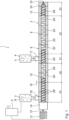
- a device 1 for treating and processing material M comprises a multi-shaft screw machine 2, a first metering device 3, a second metering device 4 and a control device 5.
- the material M is in particular a plastic material.
- the multi-shaft screw machine 2 comprises a housing 6 in which two mutually penetrating housing bores 7, 8 are formed.
- the housing bores 7, 8 have the shape of a horizontal figure eight in cross section.
- Gusset areas Z are created.
- the tapered areas of the housing 6 are referred to as gusset areas Z.
- the gusset areas Z are in Fig. 3 illustrated.
- treatment element shafts 9, 10 are rotatably arranged about associated axes of rotation 11, 12.
- the treatment element shafts 9, 10 can be driven in rotation in the same direction, i.e. in the same directions of rotation, by means of a drive motor 13 via a transfer case 14.
- a clutch 15 is arranged between the drive motor 13 and the transfer case 14.
- a first feed opening 16 and a second feed opening 17 are formed in the housing 6, which open into the housing bores 7, 8.
- the second feed opening 17 is arranged downstream of the first feed opening 16 in a conveying direction 18.
- the first metering device 3 opens into the first feed opening 16 and serves to feed the material M.
- the second metering device 4 opens into the second feed opening 17 and serves to feed at least one additive A.
- the first metering device 3 and / or the second metering device 4 is, for example designed as a gravimetric dosing device.
- the multi-shaft screw machine 2 successively comprises, in the conveying direction 18, a first feed zone 19, a melting zone 20, a second feed zone 21, a homogenization zone 22 and a discharge zone 23.
- the housing 6 is closed in the discharge zone 23 by a discharge plate 24, which has a discharge opening 25 trains.
- the treatment element shafts 9, 10 each comprise a profiled shaft 26, 27, on which screw elements 28, 28 ', kneading elements 29, 29' and treatment elements according to the invention are arranged next to each other in pairs 30, 30 'are arranged.
- screw elements 28, 28 'are arranged on the shafts 26, 27 in a torque-transmitting manner.
- treatment elements 30, 30' and kneading elements 29, 29' according to the invention are arranged on the shafts 26, 27 in a torque-transmitting manner.
- screw elements 28, 28 'are arranged on the shafts 26, 27 in a torque-transmitting manner.
- treatment elements 30, 30' and kneading elements 29, 29' are arranged on the shafts 26, 27 in a torque-transmitting manner.
- screw elements 28, 28 ' are arranged on the shafts 26, 27 in a torque-transmitting manner.
- the screw elements 28, 28' and/or the kneading elements 29, 29' are of conventional design.
- the screw elements 28, 28' and/or the kneading elements 29, 29' and/or the treatment elements 30, 30' according to the invention are, in particular, designed to have two flights.
- the kneading elements 29, 29' are designed, for example, as individual kneading disks and/or as kneading blocks with several kneading disks connected in one piece to one another.
- the treatment elements 30, 30' according to the invention are designed identically. Only one treatment element 30 is described below.
- the treatment element 30 is used to treat and/or melt material M.
- the treatment element 30 comprises a conveying section 31, a melting section 32 and a support section 33.
- the melting section 32 is arranged after the conveying section 31 in the conveying direction 18.
- the conveying section 31 and the melting section 32 are connected to one another in one piece.
- the support section 33 is arranged in the conveying direction 18 after the melting section 32.
- the Melting section 32 and the support section 33 are connected to one another in one piece.
- the treatment element 30 has a profiled bore 34 which runs through the conveying section 31, the melting section 32 and the support section 33.
- the profiled bore 34 serves to positively arrange the treatment element 30 on the associated profiled shaft 26, so that a torque can be transferred from the shaft 26 to the treatment element 30.
- the conveying section 31 is designed as a conveying element or screw element.
- the conveying section 31 includes a first side S 1F directed upstream in the conveying direction 18 and a second side S 2F directed downstream in the conveying direction 18.
- the conveyor section 31 has a two-flight profile.
- the conveying section 31 has an outer diameter D AF and a length L F in the conveying direction 18.
- the conveying section 31 defines a helical line S F , which has a pitch P F for a full revolution, i.e. at an angle of 360 °.
- the pitch P F is also referred to as the pitch.
- L F /P F 0.5.
- the melting section 32 comprises a number N of kneading disks, whereby the following generally applies: 1 ⁇ N ⁇ 7, in particular 2 ⁇ N ⁇ 6, and in particular 3 ⁇ N ⁇ 5.
- N 2.
- the melting section 32 thus comprises a first kneading disk 35 and a second kneading disk 36.
- a first spacer element 37 is arranged between the first kneading disk 35 and the second kneading disk 36.
- the spacer element 37 is arranged in the conveying direction 18 after the first kneading disk 35.
- the second kneading disk 36 is arranged in the conveying direction 18 after the spacer element 37.
- the first kneading disk 35, the spacer element 37 and the second kneading disk 36 are formed in one piece with one another.
- the first kneading disk 35 has a first side S 1A that is directed upstream in the conveying direction 18. Furthermore, the first kneading disk 35 has a second side S 2A which is directed downstream in the conveying direction 18. Accordingly, the second kneading disk 36 has a first side S 3A that is directed upstream in the conveying direction 18 and a second side S 4A that is directed downstream in the conveying direction 18.
- the second side S 2F of the conveying section 31 is connected in one piece to the first side S 1A of the first kneading disk 35.
- An offset angle b is defined between the conveying section 31 and the melting section 32, i.e. between the second side S 2F of the conveying section 31 and the first side S 1A of the first kneading disk 35, whereby the following generally applies: 0° ⁇ b ⁇ 90°, in particular 5 ° ⁇ b ⁇ 45°, and in particular 10° ⁇ b ⁇ 15°.
- b 0°.
- the offset angle b is just in Fig. 6 illustrated.
- the first kneading disk 35 and the second kneading disk 36 are twisted.
- the first kneading disk 35 has a twist angle d between the sides S 1A and S 2A .
- the second kneading disk 36 has a twist angle d between the sides S A3 and S A4 .
- d 15°.
- An offset angle c is formed between the first side S 1A of the first kneading disk 35 and the first side S 3A of the second kneading disk 36. Since the kneading disks 35, 36 have an identical twist angle d, the offset angle c is also formed between the second side S 2A of the first kneading disk 35 and the second side S 4A of the second kneading disk 36.
- the following generally applies to the offset angle c: 0° ⁇ c ⁇ 90°, in particular 15° ⁇ c ⁇ 75°, and in particular 30° ⁇ c ⁇ 60°.
- c 45°.
- an offset angle e is formed between the second side S 2A of the first kneading disk 35 and the first side S 3A of the second kneading disk 36.
- the following applies in particular to the offset angle e: e c - d.
- e 30°.
- the kneading disks 35, 36 have an outer diameter D AA and a width L A in the conveying direction 18.
- the outer diameter D AA of the kneading disks 35, 36 can be identical and/or different.
- the width L A of the kneading disks 35, 36 can be identical and/or different be.
- L A /D AA of the width L A to the outer diameter D AA the following applies in particular: 0.1 ⁇ L A /D AA ⁇ 0.4, in particular 0.15 ⁇ L A /D AA ⁇ 0.35, and in particular 0.2 ⁇ L A /D AA ⁇ 0.3.
- the kneading disks 35, 36 define a helical line S A due to the twist or the twist angle d.
- the helical line S A has a pitch P A for one full revolution, i.e. at an angle of 360°.
- the pitch P A is also referred to as the pitch.
- the pitch P A is in Fig. 5 merely hinted at. The following applies in particular to a ratio P A /D AA : 5 ⁇ P A /D AA ⁇ 10, in particular 6 ⁇ P A /D AA ⁇ 9, and in particular 7 ⁇ P A /D AA ⁇ 8.
- the support section 33 comprises a kneading disk 38 and a second spacer element 39.
- the kneading disk 38 is connected in one piece to the second spacer element 39.
- the kneading disk 38 is arranged in the conveying direction 18 after the second spacer element 39.
- the kneading disk 38 includes a first side S 1S directed upstream in the conveying direction 18 and a second side S 2S directed downstream in the conveying direction 18.
- the second spacer element 39 is connected in one piece to the second side S 4A of the kneading disk 36 and the first side Sis of the kneading disk 38.
- the kneading disk 38 is untwisted or not twisted. This means that a twist angle between the first side S 1S and the second side S 2S is zero. The first side S 1S and the second side S 2S of the kneading disk 38 are therefore congruent with one another in the conveying direction 18.
- the kneading disk 38 has an outer diameter D AS and a width Ls in the conveying direction 18.
- L S /D AS of width Ls to the Outer diameter D AS applies in particular: 0.05 ⁇ L S /D AS ⁇ 0.5, in particular 0.1 ⁇ L S /D AS ⁇ 0.35, and in particular 0.15 ⁇ L S /D AS ⁇ 0.2 .
- the spacer elements 37, 39 each have an outer diameter D AD and a width L D in the conveying direction 18.
- the outer diameter D AD of the spacer elements 37, 39 can be identical and/or different.
- the width L D of the spacer elements 37, 39 can be identical and/or different.
- L D /D AD of the width L D to the outer diameter D AD the following applies in particular: 0 ⁇ L D /D AD ⁇ 0.1, and in particular 0.01 ⁇ L D /D AD ⁇ 0.02.
- D AA ⁇ D AS and/or D AF ⁇ D AS The following applies in particular: D AA ⁇ D AS and/or D AF ⁇ D AS . Furthermore, D AD ⁇ D AS and/or D AD ⁇ D AA and/or D AD ⁇ D AF applies in particular.
- the housing bores 7, 8 have a diameter D.
- the functionality of the device 1 and the treatment elements 30, 30 'according to the invention are described below:
- the material M to be processed is fed as bulk material, in particular as powder and/or granules, by means of the first metering device 3 through the first feed opening 16 into the multi-shaft screw machine 2.
- the material M is conveyed in the conveying direction 18 to the melting zone 20 by means of the screw elements 28, 28 '.
- the material M is melted by means of the treatment elements 30, 30 'according to the invention and the kneading elements 29, 29' arranged thereafter in the conveying direction 18.
- the treatment elements 30, 30 reduce the load on the shafts 26, 27, on the treatment elements 30, 30' themselves and on the housing 6. Because the conveying section 31 and the melting section 32 are formed in one piece with one another, even at high Loads of the conveying section 31 and the melting section 32 are not pressed apart, so that no gap is formed in front of the first kneading disk 35 and material M or a melt already produced from the material M could penetrate into a resulting gap.
- the rigidity of the treatment elements 30, 30' is increased in the critical transition region between the conveying section 31 and the melting section 32, so that deformations and relative movements of the treatment elements 30, 30' and the associated shafts 26, 27 are reduced.
- the support section 33 which is connected in one piece to the melting section 32, additionally reduces relative movements and deformations of the treatment elements 30, 30 '.
- the loads on the treatment elements 30, 30 ', on the shafts 26, 27 and on the housing 6 are reduced, particularly in the gusset areas Z.
- the offset angles b, c and e as well as the twist angle d, the outer diameters D AF , D AA and D AS as well as the pitches P F and P A as well as the length L F and the widths L A and Ls can be used Load on the treatment elements 30, 30 'can be adjusted in the desired manner.
- At least one additive A is fed through the second feed opening 17 into the multi-shaft screw machine 2 by means of the second metering device 4.
- the at least one additive A is fed into the melted material M in the second feed zone 21.
- the screw elements 28, 28' By means of the screw elements 28, 28', the melted material M and the at least one additive A are conveyed in the conveying direction 18 to the homogenization zone 22.
- the at least one additive A is melted by means of the treatment elements 30, 30 'according to the invention and the kneading elements 29, 29' arranged thereafter and mixed into the melted material M.
- the mixture is homogenized in the homogenization zone 22.
- the advantages of the treatment elements 30, 30' according to the invention correspond to the advantages of the treatment elements 30, 30' arranged in the melting zone 20.
- the homogenized mixture is discharged in the usual way through the discharge opening 25.
- the kneading disks 35, 36 of the melting section 32 have edge breaks 40, 41.
- First edge breaks 40 are designed as chamfers which are arranged on the first side S 1A of the first kneading disk 35 and form a beveled surface between the first side S 1A and a peripheral side U 1A of the first kneading disk 35.
- Second edge breaks 41 are formed on the peripheral side U 1A of the first kneading disk 35 and on a peripheral side U 2A of the second kneading disk 36. In comparison to the first exemplary embodiment, the edge breaks 41 lead to edge-free peripheral sides U 1A and U 2A . To illustrate an edge break 41 is shown in Fig. 9 a fictitious edge is drawn on the circumferential side U 2A , which is actually not present due to the edge break 41.
- the edge breaks 40, 41 reduce the material volume of the treatment element 30 or 30', so that the free volume for the material M to be processed in the housing bores 7, 8 is increased. This further reduces the load on the treatment elements 30, 30 ', the shafts 26, 27 and the housing 6. Due to the edge breaks 41, the kneading disks 35, 36 have an involute profile in the area of the peripheral sides U 1A and U 2A . With regard to the further structure and functionality, reference is made to the description of the first exemplary embodiment.
Abstract
Ein Behandlungselement (30, 30') zum Behandeln von Material mittels einer Schneckenmaschine umfasst einen Förderabschnitt (31) und einen Aufschmelzabschnitt (32). Der Aufschmelzabschnitt (32) ist in einer Förderrichtung (18) nach dem Förderabschnitt (31) angeordnet und einteilig mit dem Förderabschnitt (31) verbunden. Hierdurch wird der Verschleiß reduziert und die Standzeit erhöht.
Description
- Die Erfindung betrifft ein Behandlungselement zum Behandeln von Material mittels einer Schneckenmaschine. Ferner betrifft die Erfindung eine Schneckenmaschine mit einem derartigen Behandlungselement.
- Aus der
EP 1 508 424 A1 (entsprichtUS 2005/0041521 A1 ) ist eine Schneckenmaschine bekannt, die ein Gehäuse und profilierte Wellen mit darauf angeordneten Behandlungselementen umfasst. In einer Einzugszone sind Förderelemente bzw. Schneckenelemente als Behandlungselemente auf den profilierten Wellen angeordnet. In einer Misch- und Knetzone, die in einer Förderrichtung stromabwärts zu der Einzugszone ausgebildet ist, sind zum Aufschmelzen und Homogenisieren des aufzubereitenden Materials Knetblöcke als Behandlungselemente auf den profilierten Wellen angeordnet. Die Knetblöcke umfassen jeweils mehrere einteilig miteinander ausgebildete Knetscheiben. In einer stromabwärts zu der Misch- und Knetzone ausgebildeten Druckaufbauzone sind wiederum Schneckenelemente als Behandlungselemente auf den profilierten Wellen angeordnet. - In der Misch- und Knetzone wird das aufzubereitende Material aufgeschmolzen. Dort wirken auf die Behandlungselemente und die zugehörigen Wellen hohe Belastungen, die einen hohen Verschleiß an den Behandlungselementen, den Wellen und dem Gehäuse verursachen und deren Standzeiten reduzieren.
- Der Erfindung liegt die Aufgabe zugrunde, ein Behandlungselement zum Behandeln von Material mittels einer Schneckenmaschine zu schaffen, das einen geringen Verschleiß und eine hohe Standzeit hat.
- Diese Aufgabe wird durch ein Behandlungselement mit den Merkmalen des Anspruchs 1 gelöst. Das Behandlungselement dient zum Behandeln und/oder Aufschmelzen von Material, insbesondere von Kunststoff-Material, mittels einer Schneckenmaschine. Das Behandlungselement umfasst einen Förderabschnitt und einen in der Förderrichtung danach angeordneten Aufschmelzabschnitt, die einteilig miteinander verbunden sind. Der Förderabschnitt umfasst insbesondere ein Förderelement bzw. Schneckenelement zum Fördern des zu behandelnden Materials. Der Aufschmelzabschnitt umfasst insbesondere mindestens eine Knetscheibe. Die mindestens eine Knetscheibe dient zum Einbringen von Energie in das zu behandelnde Material und/oder zum Aufschmelzen des zu behandelnden Materials. Das Behandlungselement ist insbesondere als Kombi-Behandlungselement ausgebildet, da durch die einteilige Ausbildung des Förderabschnitts und des Aufschmelzabschnitts die Funktionen des Förderns und des Aufschmelzens miteinander kombiniert sind. Das Behandlungselement umfasst insbesondere eine profilierte Durchgangsbohrung zum Befestigen des Behandlungselements auf einer profilierten Welle einer Schneckenmaschine.
- Durch die einteilige Ausbildung des Förderabschnitts und des Aufschmelzabschnitts kann trotz hoher Belastungen zwischen dem Förderabschnitt und dem Aufschmelzabschnitt kein Spalt entstehen, in den Material bzw. Materialschmelze eindringen könnte. Durch die einteilige Ausbildung ist somit die spezifische Belastung, also die Belastung pro Flächeneinheit, auf das Behandlungselement sowie eine zugehörige profilierte Welle reduziert. Darüber hinaus ist die Steifigkeit des Behandlungselements an dem kritischen Übergang zwischen dem Förderabschnitt und dem Aufschmelzabschnitt erhöht, so dass Relativbewegungen und Verformungen des Behandlungselements im Betrieb der Schneckenmaschine reduziert sind. Hierdurch wird der Verschleiß reduziert und die Standzeit erhöht. Insbesondere kann die Gefahr von Brüchen der Wellen reduziert werden.
- Ein Behandlungselement nach Anspruch 2 gewährleistet einen geringen Verschleiß und eine hohe Standzeit. Der Aufschmelzabschnitt ist einteilig ausgebildet. Insbesondere sind mehrere Knetscheiben einteilig miteinander verbunden. Weist der Aufschmelzabschnitt mehrere miteinander verbundene Knetscheiben auf, so werden in dem Aufschmelzabschnitt auftretende Belastungen im Betrieb der Schneckenmaschine über mehrere Knetscheiben verteilt. Die jeweilige Knetscheibe kann eingängig bis viergängig ausgebildet sein. Vorzugsweise ist die jeweilige Knetscheibe zweigängig oder dreigängig ausgebildet. Die Knetscheiben des Aufschmelzabschnitts können geometrisch identisch und/oder geometrisch unterschiedlich ausgebildet sein.
- Ein Behandlungselement nach Anspruch 3 gewährleistet einen geringen Verschleiß und eine hohe Standzeit. Jede Knetscheibe hat eine erste Seite, die bezogen auf die Förderrichtung stromaufwärts gerichtet ist, und eine zweite Seite, die bezogen auf die Förderrichtung stromabwärts gerichtet ist. Zwei unmittelbar nacheinander angeordnete Knetscheiben haben an ihren ersten Seiten und/oder an ihren zweiten Seiten zueinander einen Versatzwinkel c, so dass durch die Anordnung der Knetscheiben das Fördern des Materials unterstützt wird. Durch den Versatzwinkel c ist die Verweilzeit des Materials in dem Aufschmelzabschnitt und somit die Energieeinleitung bzw. Aufschmelzung einerseits und die Belastung andererseits einstellbar.
- Ein Behandlungselement nach Anspruch 4 gewährleistet einen geringen Verschleiß und eine hohe Standzeit. Jede Knetscheibe hat eine erste Seite, die bezogen auf die Förderrichtung stromaufwärts gerichtet ist, und eine zweite Seite, die bezogen auf die Förderrichtung stromabwärts gerichtet ist. Die erste Seite ist zu der zweiten Seite um einen Verdrillwinkel d versetzt, so dass die Knetscheibe von der ersten Seite zu der zweiten Seite verdrillt ist. Wird das Behandlungselement auf einer zugehörigen profilierten Welle einer Schneckenmaschine angeordnet, so wird hierdurch die Belastung auf das jeweilige Behandlungselement reduziert. In einem Gehäuse einer Mehrwellen-Schneckenmaschine sind mindestens zwei einander durchdringende Gehäusebohrungen ausgebildet, so dass das Gehäuse mindestens einen Zwickelbereich ausbildet. Als Zwickelbereich ist der spitz zulaufende Gehäusebereich bezeichnet, der durch die sich schneidenden mindestens zwei Gehäusebohrungen gebildet ist. Durch den Verdrillwinkel wird verhindert, dass das aufzubereitende Material in dem Zwickelbereich eingeklemmt wird. Der Verdrillwinkel erzeugt eine fördernde Wirkung. Der Verdrillwinkel erzeugt einen auf das Material wirkenden Axialimpuls und dadurch eine Vorzugsrichtung, so dass in dem Zwickelbereich geringere Kräfte auf das Material und somit auch auf das Behandlungselement wirken, was zu einer geringeren Beanspruchung und zu weniger Schäden führt. Darüber hinaus wird durch den Verdrillwinkel das Volumen des Materials reduziert, das in dem Zwickelbereich gleichzeitig eingeschlossen ist. Durch das Absenken der in dem Zwickelbereich wirkenden Kräfte wird die Belastung, insbesondere ein Biegemoment und/oder ein Torsionsmoment, das auf das Behandlungselement und die zugehörige Welle wirkt, reduziert. Schwingungen der Behandlungselementwellen der Mehrwellen-Schneckenmaschine können reduziert werden, so dass Verschleiß und Schäden an dem Gehäuse und/oder an den Behandlungselementen reduziert und/oder an den Wellen vermieden werden.
- Ein Behandlungselement nach Anspruch 5 gewährleistet einen geringen Verschleiß und eine hohe Standzeit. Weist der Aufschmelzabschnitt mehrere Knetscheiben auf, so können einzelne der Knetscheiben oder alle Knetscheiben einen Verdrillwinkel d haben. Der Verdrillwinkel der Knetscheiben kann identisch und/oder unterschiedlich sein.
- Ein Behandlungselement nach Anspruch 6 gewährleistet einen geringen Verschleiß und eine hohe Standzeit. Aufgrund der Verdrillung der mindestens einen Knetscheibe definiert das jeweilige Profil der Knetscheibe in der Förderrichtung eine Schraubenlinie. Diese Schraubenlinie definiert bei einer vollen Umdrehung, also einem Winkel von 360°, in der Förderrichtung die Ganghöhe PA. Die Ganghöhe PA wird auch als Steigung bezeichnet. Durch das Verhältnis der Ganghöhe PA zu dem Außendurchmesser DAA wird bei einer Mehrwellen-Schneckenmaschine die Belastung im Zwickelbereich zwischen benachbarten, paarweise angeordneten Behandlungselementen reduziert. Der Verdrillwinkel d ergibt sich aus der Ganghöhe PA und einer Breite LA der jeweiligen Knetscheibe.
- Ein Behandlungselement nach Anspruch 7 gewährleistet einen geringen Verschleiß und eine hohe Standzeit. Jede Knetscheibe hat eine erste Seite, die bezogen auf die Förderrichtung stromaufwärts gerichtet ist, und eine zweite Seite, die bezogen auf die Förderrichtung stromabwärts gerichtet ist. Zwei unmittelbar nacheinander angeordnete Knetscheiben sind zwischen der zweiten Seite der Knetscheibe, die stromaufwärts angeordnet ist, und der ersten Seite der Knetscheibe, die stromabwärts angeordnet ist, miteinander verbunden. Zwischen der zweiten Seite der stromaufwärts angeordneten Knetscheibe und der ersten Seite der stromabwärts angeordneten Knetscheibe ist der Versatzwinkel e ausgebildet. Für den Versatzwinkel e gilt insbesondere: e = b - d, wobei b einen Versatzwinkel zwischen ersten Seiten und/oder zweiten Seiten von zwei aufeinanderfolgenden Knetscheiben und d einen Verdrillwinkel der stromaufwärts angeordneten Knetscheibe bezeichnet. Durch den Versatzwinkel e kann ein Fördern des Materials unterstützt werden. Hierdurch kann die Verweilzeit des Materials in dem Aufschmelzabschnitt beeinflusst werden. Durch den Versatzwinkel e wird einerseits der Energieeintrag und die Aufschmelzung und andererseits die Belastung des Behandlungselements beeinflusst bzw. eingestellt.
- Ein Behandlungselement nach Anspruch 8 gewährleistet einen geringen Verschleiß und eine hohe Standzeit. Die Breite LA ist auf die Förderrichtung bezogen. Durch die Anzahl der Knetscheiben und/oder das Verhältnis der Breite LA zu dem Außendurchmesser DAA wird einerseits der Energieeintrag in das Material und das Aufschmelzen des Materials und andererseits die Belastung des Behandlungselements beeinflusst. Je mehr Knetscheiben der Aufschmelzabschnitt umfasst und/oder je breiter die jeweilige Knetscheibe ist, desto steifer und stabiler ist das Behandlungselement.
- Ein Behandlungselement nach Anspruch 9 gewährleistet einen geringen Verschleiß und eine hohe Standzeit. Die jeweilige Knetscheibe hat mehrere Kanten. Eine erste umlaufende Kante ist zwischen einer ersten Seite, die bezogen auf die Förderrichtung stromaufwärts gerichtet ist, und einer Umfangsseite angeordnet. Entsprechend ist eine zweite umlaufende Kante zwischen einer zweiten Seite, die bezogen auf die Förderrichtung stromabwärts gerichtet ist, und der Umfangsseite angeordnet. Dritte Kanten können an der Umfangsseite angeordnet sein und verlaufen quer zu der ersten Kante und/oder der zweiten Kante. Beispielsweise verlaufen bei mehrgängigen Knetscheiben Kanten zwischen dem jeweiligen Kammbereich und dem benachbarten Flankenbereich. Durch den Kantenbruch wird das Volumen der jeweiligen Knetscheibe reduziert, so dass umgekehrt das freie Volumen in einer Gehäusebohrung einer Schneckenmaschine erhöht wird. Dadurch, dass das freie Volumen erhöht wird, wird die Belastung durch das Material auf das Behandlungselement und die zugehörige profilierte Welle reduziert. Insbesondere wird das freie Volumen in dem Zwickelbereich vergrößert, so dass die Belastung in dem Zwickelbereich reduziert wird. Der Kantenbruch ist insbesondere als Fase und/oder Rundung ausgeführt. Vorzugsweise verläuft der Kantenbruch über mindestens 25 %, insbesondere mindestens 50 % und insbesondere mindestens 75 % der Länge der jeweiligen Kante. Vorzugsweise kann die Umfangsseite der jeweiligen Knetscheibe ohne eine Kante ausgebildet sein. Ein derartiges Profil einer Knetscheibe wird auch als involutes Profil bzw. die Knetscheibe als involute Knetscheibe bezeichnet. Derartige Profile sind beispielsweise in der
WO 2011/039 016 A1 offenbart, worauf verwiesen wird. - Ein Behandlungselement nach Anspruch 10 gewährleistet einen geringen Verschleiß und eine hohe Standzeit. Vorzugsweise umfasst der Förderabschnitt ein Förderelement bzw. ein Schneckenelement. Das Profil des Förderabschnitts bzw. Förderelements ist insbesondere ein- bis viergängig ausgebildet, vorzugsweise zweigängig oder dreigängig. Das Profil des Förderabschnitts bzw. des Förderelements definiert in der Förderrichtung eine Schraubenlinie. Die Schraubenlinie definiert bei einer vollen Umdrehung, also bei einem Winkel von 360°, eine Ganghöhe PF. Diese Ganghöhe wird auch als Steigung bezeichnet. Durch das Verhältnis der Ganghöhe PF zu dem Außendurchmesser DAF wird die Förderwirkung des Förderabschnitts eingestellt. Die Förderwirkung bestimmt, welche Menge an Material pro Zeiteinheit dem Aufschmelzabschnitt zugeführt wird. Über das Verhältnis der Ganghöhe PF zu dem Außendurchmesser DAF wird somit die Belastung in dem Übergangsbereich zwischen dem Förderabschnitt und dem Aufschmelzabschnitt eingestellt. Der Förderabschnitt kann ein Erdmenger-Profil, ein Schubkanten-Profil und/oder ein involutes Profil aufweisen.
- Ein Behandlungselement nach Anspruch 11 gewährleistet einen geringen Verschleiß und eine hohe Standzeit. Die Länge LF ist auf die Förderrichtung bezogen. Das Profil des Förderabschnitts definiert in der Förderrichtung eine Schraubenlinie. Die Schraubenlinie hat bei einer vollen Umdrehung, also bei einem Winkel von 360°, eine Ganghöhe PF. Die Ganghöhe PF wird auch als Steigung bezeichnet. Durch das Verhältnis der Länge LF zu der Ganghöhe PF wird die Förderwirkung des Förderabschnitts eingestellt. Hierdurch wird die Belastung in dem Übergangsbereich zwischen dem Förderabschnitt und dem Aufschmelzabschnitt eingestellt.
- Ein Behandlungselement nach Anspruch 12 gewährleistet einen geringen Verschleiß und eine hohe Standzeit. Durch den Versatzwinkel b wird die Förderwirkung und die Belastung in dem Übergangsbereich zwischen dem Förderabschnitt und dem Aufschmelzabschnitt eingestellt. Der Aufschmelzabschnitt hat insbesondere eine erste Seite, die bezogen auf die Förderrichtung stromaufwärts gerichtet ist. Demgegenüber hat der Förderabschnitt insbesondere eine zweite Seite, die bezogen auf die Förderrichtung stromabwärts gerichtet ist. Die erste Seite des Aufschmelzabschnitts ist mit der zweiten Seite des Förderabschnitts insbesondere einteilig verbunden, wobei zwischen der zweiten Seite des Förderabschnitts und der ersten Seite des Aufschmelzabschnitts der Versatzwinkel b ausgebildet ist. Vorzugsweise ist der Versatzwinkel b zwischen einer zweiten Seite eines Förderelements des Förderabschnitts und einer ersten Seite einer Knetscheibe des Aufschmelzabschnitts ausgebildet. Für den Versatzwinkel b gilt insbesondere: 0° ≤ b ≤ 5°, insbesondere 0° ≤ b ≤ 1°, und insbesondere b = 0°.
- Ein Behandlungselement nach Anspruch 13 gewährleistet einen geringen Verschleiß und eine hohe Standzeit. Durch den Stützabschnitt werden radiale Bewegungen des Behandlungselements reduziert. Hierdurch werden der Verschleiß und etwaige Schäden reduziert und die Standzeit des Behandlungselements erhöht. Durch den Stützabschnitt wird der funktionsgemäße Einsatz des Aufschmelzabschnitts sichergestellt. Darüber hinaus wird die Steifigkeit des Behandlungselements erhöht. Die auf das Behandlungselement wirkenden Belastungen werden über die Länge des Behandlungselements besser verteilt.
- Vorzugsweise weist der Stützabschnitt eine erste Seite auf, die bezogen auf die Förderrichtung stromaufwärts gerichtet ist und mit dem Aufschmelzabschnitt verbunden ist. Der Aufschmelzabschnitt weist vorzugsweise eine zweite Seite auf, die bezogen auf die Förderrichtung stromabwärts gerichtet ist und mit dem Stützabschnitt verbunden ist. Zwischen der zweiten Seite des Aufschmelzabschnitts und der ersten Seite des Stützabschnitts ist insbesondere ein Versatzwinkel f ausgebildet, wobei insbesondere gilt: - 90° ≤ f ≤ 90°, insbesondere - 45° ≤ f ≤ 45°, insbesondere - 15° ≤ f ≤ 15°, insbesondere - 5° ≤ f ≤ 5°, insbesondere - 1° ≤ f ≤ 1°, und insbesondere f = 0°. Positive Versatzwinkel f sind Versatzwinkel entgegen der vordefinierten Drehrichtung. Positive Versatzwinkel wirken fördernd. Demgegenüber sind negative Versatzwinkel f Versatzwinkel in der vordefinierten Drehrichtung. Negative Versatzwinkel wirken rückstauend. Je nach aufzubereitendem Material kann nach der Aufschmelzung eine Förderung oder ein Rückstau des Materials erwünscht sein. Vorzugsweise ist der Versatzwinkel f zwischen einer zweiten Seite einer Knetscheibe des Aufschmelzabschnitts und einer ersten Seite einer Knetscheibe des Stützabschnitts ausgebildet. Vorzugsweise ist der Versatzwinkel f gleich dem Versatzwinkel e.
- Ein Behandlungselement nach Anspruch 14 gewährleistet einen geringen Verschleiß und eine hohe Standzeit. Der Stützabschnitt umfasst eine Anzahl M von Knetscheiben, wobei insbesondere gilt: 1 ≤ M ≤ 4, und insbesondere 2 ≤ M ≤ 3. Die Knetscheiben können eingängig bis viergängig ausgebildet sein, vorzugsweise sind die Knetscheiben zweigängig oder dreigängig ausgebildet. Die Knetscheiben können identisch und/oder unterschiedlich ausgebildet sein.
- Vorzugsweise umfasst der Stützabschnitt mindestens zwei Knetscheiben, die in der Förderrichtung unmittelbar nacheinander angeordnet sind. Jede der Knetscheiben umfasst eine erste Seite, die bezogen auf die Förderrichtung stromaufwärts gerichtet ist, und eine zweite Seite, die bezogen auf die Förderrichtung stromabwärts gerichtet ist. Zwischen den ersten Seiten und/oder den zweiten Seiten der mindestens zwei Knetscheiben ist ein Versatzwinkel g ausgebildet, wobei insbesondere gilt: 0° ≤ g ≤ 180°, insbesondere 15° ≤ g ≤ 120°, und insbesondere 30° ≤ g ≤ 90°.
- Die mindestens eine Knetscheibe ist vorzugsweise unverdrillt bzw. nicht verdrillt. Vorzugsweise ist jede Knetscheibe des Stützabschnitts bzw. sind alle Knetscheiben des Stützabschnitts unverdrillt bzw. nicht verdrillt. Ein Verdrillwinkel beträgt somit 0°. Jede Knetscheibe weist eine erste Seite auf, die bezogen auf die Förderrichtung stromaufwärts gerichtet ist, und eine zweite Seite, die bezogen auf die Förderrichtung stromabwärts gerichtet ist. Die erste Seite und die zweite Seite der jeweiligen Knetscheibe sind somit deckungsgleich und/oder weisen keinen Verdrillwinkel zueinander auf.
- Ein Behandlungselement nach Anspruch 15 gewährleistet einen geringen Verschleiß und eine hohe Standzeit. Die Breite Ls ist auf die Förderrichtung bezogen. Weist der Stützabschnitt mehrere Knetscheiben auf, so können die Knetscheiben eine identische Breite Ls und/oder unterschiedliche Breiten Ls haben. Vorzugsweise ist die Breite Ls der in Förderrichtung gesehen letzten Knetscheibe des Stützabschnitts geringer als die Breite Ls einer stromaufwärts angeordneten Knetscheibe des Stützabschnitts. Hierdurch kann vermieden werden, dass eine unerwünscht große Breite entsteht, wenn eine stromabwärts angeordnete Knetscheibe eines weiteren Behandlungselements ohne Versatzwinkel angeordnet wird.
- Ein Behandlungselement nach Anspruch 16 gewährleistet einen geringen Verschleiß und eine hohe Standzeit. Der Aufschmelzabschnitt und/oder der Förderabschnitt ist im Vergleich zu dem Stützabschnitt durchmesserreduziert. Dadurch, dass der Außendurchmesser DAA und/oder der Außendurchmesser DAF im Vergleich zu dem Außendurchmesser DAS reduziert ist, wird die Belastung auf das Behandlungselement im Bereich des Aufschmelzabschnitts und/oder des Förderabschnitts reduziert. Gleichzeitig stellt der Stützabschnitt aufgrund des größeren Außendurchmessers DAS eine hohe Stützwirkung bereit, so dass radiale Bewegungen des Behandlungselements reduziert werden.
- Der Außendurchmesser DAA des Aufschmelzabschnitts kann über die Länge des Aufschmelzabschnitts bzw. in Bezug auf nacheinander angeordnete Knetscheiben des Aufschmelzabschnitts konstant sein und/oder in der Förderrichtung steigen und/oder in der Förderrichtung sinken. Der Außendurchmesser DAA kann sich entlang der Länge des Aufschmelzabschnitts stetig und/oder unstetig ändern.
- Der Außendurchmesser DAF des Förderabschnitts kann über die Länge des Förderabschnitts bzw. in Bezug auf nacheinander angeordnete Förderelemente des Förderabschnitts konstant sein und/oder in der Förderrichtung steigen und/oder in der Förderrichtung sinken. Der Außendurchmesser DAF kann sich entlang der Länge des Förderabschnitts stetig und/oder unstetig ändern.
- Vorzugsweise ist zwischen dem Förderabschnitt und dem Aufschmelzabschnitt und/oder zwischen dem Aufschmelzabschnitt und dem Stützabschnitt ein Distanzelement angeordnet. Das Distanzelement ist einteilig mit dem Förderabschnitt und dem Aufschmelzabschnitt bzw. mit dem Aufschmelzabschnitt und dem Stützabschnitt verbunden. Vorzugsweise ist zwischen mindestens zwei Knetscheiben des Aufschmelzabschnitts und/oder zwischen mindestens zwei Knetscheiben des Stützabschnitts ein Distanzelement angeordnet. Das Distanzelement ist einteilig mit den Knetscheiben verbunden. Das Distanzelement ist beispielsweise im Querschnitt kreisrund oder entsprechend des Profils des Förderabschnitts und/oder des Aufschmelzabschnitts und/oder des Stützabschnitts ausgebildet. Für einen Außendurchmesser DAD des Distanzelements gilt: DAD < DAF und/oder DAD < DAA und/oder DAD < DAS. Vorzugsweise gilt für eine Breite LD des jeweiligen Distanzelements bezogen auf die Förderrichtung: 0 < LD/DAD ≤ 0,1, und insbesondere 0,01 ≤ LD/DAD ≤ 0,02. Durch die Distanzelemente können die mindestens zwei Behandlungselementwellen trotz fertigungstechnischer Spiele frei zueinander in den mindestens zwei Gehäusebohrungen rotieren. Ein Innendurchmesser des Distanzelements ist vorzugsweise größer als ein Innendurchmesser der mindestens zwei Knetscheiben.
- Der Erfindung liegt ferner die Aufgabe zugrunde, eine Schneckenmaschine zum Behandeln von Material zu schaffen, die einen geringen Verschleiß und eine hohe Standzeit hat.
- Diese Aufgabe wird durch eine Schneckenmaschine mit den Merkmalen des Anspruchs 17 gelöst. Die Vorteile der erfindungsgemäßen Schneckenmaschine entsprechen den Vorteilen des beschriebenen Behandlungselements. Vorzugsweise weist die Schneckenmaschine mindestens eine Behandlungselementwelle auf, die eine profilierte Welle umfasst. Auf der profilierten Welle ist mindestens ein erfindungsgemäßes Behandlungselement angeordnet. In jeder Gehäusebohrung ist eine zugehörige Behandlungselementwelle drehbar angeordnet.
- Vorzugsweise ist das mindestens eine Behandlungselement in einer Aufschmelzzone und/oder einer Homogenisierungszone der Schneckenmaschine angeordnet. In der Aufschmelzzone und/oder der Homogenisierungszone wirken hohe Belastungen, die durch das mindestens eine erfindungsgemäße Behandlungselement reduziert werden. Vorzugsweise umfasst das mindestens eine erfindungsgemäße Behandlungselement mindestens eine Knetscheibe und ist derart in der Aufschmelzzone und/oder der Homogenisierungszone angeordnet, dass das mindestens eine erfindungsgemäße Behandlungselement ein bezogen auf die Förderrichtung erstes Behandlungselement mit einer Knetscheibe bildet. Anders ausgedrückt, sind in der Aufschmelzzone und/oder der Homogenisierungszone vorzugsweise keine nicht erfindungsgemäßen Behandlungselemente mit einer Knetscheibe stromaufwärts zu dem mindestens einen erfindungsgemäßen Behandlungselement angeordnet.
- Vorzugsweise ist die Schneckenmaschine als Mehrwellen-Schneckenmaschine, insbesondere als Zweiwellen-Schneckenmaschine ausgebildet. Die Mehrwellen-Schneckenmaschine weist insbesondere mindestens zwei Gehäusebohrungen auf, die in dem Gehäuse ausgebildet sind. Die mindestens zwei Gehäusebohrungen schneiden einander. Hierdurch bilden die mindestens zwei Gehäusebohrungen insbesondere im Querschnitt die Form einer liegenden Acht aus. Die Mehrwellen-Schneckenmaschine umfasst mindestens zwei Behandlungselementwellen, die insbesondere jeweils eine profilierte Welle umfassen, auf der jeweils mindestens ein erfindungsgemäßes Behandlungselement angeordnet ist. Die Mehrwellen-Schneckenmaschine ist gleichsinnig rotierend ausgebildet, also mit in gleichen Drehrichtungen rotierenden mindestens zwei Behandlungselementwellen. Die mindestens zwei Behandlungselementwellen sind vorzugsweise einander dichtkämmend ausgebildet und/oder angeordnet. Vorzugsweise weist jede Behandlungselementwelle mindestens ein erfindungsgemäßes Behandlungselement auf, die bezogen auf die Förderrichtung an gleichen Positionen angeordnet sind.
- Die mindestens eine Gehäusebohrung hat einen Durchmesser D. Der Förderabschnitt weist einen Außendurchmesser DAF auf, wobei insbesondere gilt: 0,8 ≤ DAF/D < 1, insbesondere 0,9 ≤ DAF/D ≤ 0,99, und insbesondere 0,95 ≤ DAF/D ≤ 0,98.
- Der Aufschmelzabschnitt weist einen Außendurchmesser DAA auf, wobei insbesondere gilt: 0,8 ≤ DAA/D < 1, insbesondere 0,9 ≤ DAA/D ≤ 0,99, und insbesondere 0,95 ≤ DAA/D ≤ 0,98.
- Der Stützabschnitt weist einen Außendurchmesser DAS auf, wobei insbesondere gilt: 0,95 ≤ DAS/D < 1, insbesondere 0,98 ≤ DAS/D ≤ 0,998, und insbesondere 0,99 ≤ DAS/D ≤ 0,995.
- Vorzugsweise gilt: DAF/D < DAS/D und/oder DAA/D < DAS/D.
- Weitere Merkmale, Vorteile und Einzelheiten der Erfindung ergeben sich aus der nachfolgenden Beschreibung mehrerer Ausführungsbeispiele. Es zeigen:
- Fig. 1
- eine teilweise geschnitten dargestellte Vorrichtung zum Behandeln von Material mit einer Mehrwellen-Schneckenmaschine,
- Fig. 2
- eine teilweise geschnittene Draufsicht auf die Vorrichtung in
Fig. 1 , - Fig. 3
- eine Schnittdarstellung der Mehrwellen-Schneckenmaschine entlang der Schnittlinie III-III in
Fig. 2 , - Fig. 4
- eine perspektivische Ansicht von zwei paarweise nebeneinander angeordneten Behandlungselementen gemäß einem ersten Ausführungsbeispiel, die Teil der Mehrwellen-Schneckenmaschine in
Fig. 1 sind, - Fig. 5
- eine erste Seitenansicht eines der Behandlungselemente in
Fig. 4 , - Fig. 6
- eine zweite Seitenansicht des Behandlungselements in
Fig. 5 , - Fig. 7
- eine Schnittansicht durch das Behandlungselement entlang der Schnittlinie VII-VII in
Fig. 5 , - Fig. 8
- eine perspektivische Ansicht von zwei paarweise nebeneinander angeordneten Behandlungselementen gemäß einem zweiten Ausführungsbeispiel,
- Fig. 9
- eine Seitenansicht eines der Behandlungselemente in
Fig. 8 und - Fig. 10
- eine Schnittansicht durch das Behandlungselement entlang der Schnittlinie X-X in
Fig. 9 . - Nachfolgend ist anhand der
Fig. 1 bis 7 ein erstes Ausführungsbeispiel der Erfindung beschrieben. Eine Vorrichtung 1 zum Behandeln und Aufbereiten von Material M umfasst eine Mehrwellen-Schneckenmaschine 2, eine erste Dosiereinrichtung 3, eine zweite Dosiereinrichtung 4 und eine Steuereinrichtung 5. Das Material M ist insbesondere ein Kunststoff-Material. - Die Mehrwellen-Schneckenmaschine 2 umfasst ein Gehäuse 6, in dem zwei einander durchdringende Gehäusebohrungen 7, 8 ausgebildet sind. Die Gehäusebohrungen 7, 8 haben im Querschnitt die Form einer liegenden Acht. Durch die zwei einander durchdringenden Gehäusebohrungen 7, 8 entstehen Zwickelbereiche Z. Als Zwickelbereiche Z werden die spitz zulaufenden Bereiche des Gehäuses 6 bezeichnet. Die Zwickelbereiche Z sind in
Fig. 3 veranschaulicht. In den Gehäusebohrungen 7, 8 sind Behandlungselementwellen 9, 10 um zugehörige Drehachsen 11, 12 drehbar angeordnet. Die Behandlungselementwellen 9, 10 sind mittels eines Antriebsmotors 13 über ein Verteilergetriebe 14 gleichsinnig, also in gleichen Drehrichtungen, drehantreibbar. Zwischen dem Antriebsmotor 13 und dem Verteilergetriebe 14 ist eine Kupplung 15 angeordnet. - In dem Gehäuse 6 ist eine erste Zuführöffnung 16 und eine zweite Zuführöffnung 17 ausgebildet, die in die Gehäusebohrungen 7, 8 münden. Die zweite Zuführöffnung 17 ist in einer Förderrichtung 18 stromabwärts zu der ersten Zuführöffnung 16 angeordnet. Die erste Dosiereinrichtung 3 mündet in die erste Zuführöffnung 16 und dient zum Zuführen des Materials M. Die zweite Dosiereinrichtung 4 mündet in die zweite Zuführöffnung 17 und dient zum Zuführen mindestens eines Additivs A. Die erste Dosiereinrichtung 3 und/oder die zweite Dosiereinrichtung 4 ist beispielsweise als gravimetrische Dosiereinrichtung ausgebildet.
- Die Mehrwellen-Schneckenmaschine 2 umfasst in der Förderrichtung 18 nacheinander eine erste Einzugszone 19, eine Aufschmelzzone 20, eine zweite Einzugszone 21, eine Homogenisierungszone 22 und eine Austragszone 23. Das Gehäuse 6 ist in der Austragszone 23 durch eine Austragsplatte 24 abgeschlossen, die eine Austragsöffnung 25 ausbildet.
- Die Behandlungselementwellen 9, 10 umfassen jeweils eine profilierte Welle 26, 27, auf denen paarweise nebeneinander Schneckenelemente 28, 28', Knetelemente 29, 29' und erfindungsgemäße Behandlungselemente 30, 30' angeordnet sind. In der ersten Einzugszone 19 sind Schneckenelemente 28, 28' auf den Wellen 26, 27 in drehmomentübertragender Weise angeordnet. In der Aufschmelzzone 20 sind erfindungsgemäße Behandlungselemente 30, 30' und Knetelemente 29, 29' in drehmomentübertragender Weise auf den Wellen 26, 27 angeordnet. In der zweiten Einzugszone 21 sind Schneckenelemente 28, 28' in drehmomentübertragender Weise auf den Wellen 26, 27 angeordnet. In der Homogenisierungszone 22 sind erfindungsgemäße Behandlungselemente 30, 30' und Knetelemente 29, 29' in drehmomentübertragender Weise auf den Wellen 26, 27 angeordnet. In der Austragszone 23 sind Schneckenelemente 28, 28' in drehmomentübertragender Weise auf den Wellen 26, 27 angeordnet. Die Schneckenelemente 28, 28' und/oder die Knetelemente 29, 29' sind üblich ausgebildet. Die Schneckenelemente 28, 28' und/oder die Knetelemente 29, 29' und/oder die erfindungsgemäßen Behandlungselemente 30, 30' sind insbesondere zweigängig ausgebildet. Die Knetelemente 29, 29' sind beispielsweise als einzelne Knetscheiben und/oder als Knetblöcke mit mehreren einteilig miteinander verbundenen Knetscheiben ausgebildet.
- Die erfindungsgemäßen Behandlungselemente 30, 30' sind identisch ausgebildet. Nachfolgend ist lediglich ein Behandlungselement 30 beschrieben.
- Das Behandlungselement 30 dient zum Behandeln und/oder Aufschmelzen von Material M. Das Behandlungselement 30 umfasst einen Förderabschnitt 31, einen Aufschmelzabschnitt 32 und einen Stützabschnitt 33. Der Aufschmelzabschnitt 32 ist in der Förderrichtung 18 nach dem Förderabschnitt 31 angeordnet. Der Förderabschnitt 31 und der Aufschmelzabschnitt 32 sind einteilig miteinander verbunden. Der Stützabschnitt 33 ist in der Förderrichtung 18 nach dem Aufschmelzabschnitt 32 angeordnet. Der Aufschmelzabschnitt 32 und der Stützabschnitt 33 sind einteilig miteinander verbunden.
- Das Behandlungselement 30 weist eine profilierte Bohrung 34 auf, die durch den Förderabschnitt 31, den Aufschmelzabschnitt 32 und den Stützabschnitt 33 verläuft. Die profilierte Bohrung 34 dient zum formschlüssigen Anordnen des Behandlungselements 30 auf der zugehörigen profilierten Welle 26, so dass von der Welle 26 ein Drehmoment auf das Behandlungselement 30 übertragbar ist.
- Der Förderabschnitt 31 ist als Förderelement bzw. Schneckenelement ausgebildet. Der Förderabschnitt 31 umfasst eine erste Seite S1F, die in der Förderrichtung 18 stromaufwärts gerichtet ist, und eine zweite Seite S2F, die in der Förderrichtung 18 stromabwärts gerichtet ist. Der Förderabschnitt 31 hat ein zweigängiges Profil. Der Förderabschnitt 31 weist einen Außendurchmesser DAF und in der Förderrichtung 18 eine Länge LF auf. Ferner definiert der Förderabschnitt 31 eine Schraubenlinie SF, die bei einer vollen Umdrehung, also bei einem Winkel von 360°, eine Ganghöhe PF hat. Die Ganghöhe PF ist auch als Steigung bezeichnet. Für ein Verhältnis PF/DAF der Ganghöhe PF zu dem Außendurchmesser DAF gilt insbesondere: 0,75 ≤ PF/DAF ≤ 2, insbesondere 1 ≤ PF/DAF ≤ 1,75, und insbesondere 1,25 ≤ PF/DAF ≤ 1,5.
- Ferner gilt für ein Verhältnis LF/PF der Länge LF zu der Ganghöhe PF insbesondere: 0,2 ≤ LF/PF ≤ 1,5, insbesondere 0,3 ≤ LF/PF ≤ 1,2, und insbesondere 0,4 ≤ LF/PF ≤ 0,9. Für das Ausführungsbeispiel in
Fig. 5 gilt beispielsweise: LF/PF = 0,5. - Der Aufschmelzabschnitt 32 umfasst eine Anzahl N von Knetscheiben, wobei allgemein gilt: 1 ≤ N ≤ 7, insbesondere 2 ≤ N ≤ 6, und insbesondere 3 ≤ N ≤ 5. Für das Ausführungsbeispiel gemäß den
Fig. 1 bis 7 gilt beispielhaft: N = 2. Der Aufschmelzabschnitt 32 umfasst somit eine erste Knetscheibe 35 und eine zweite Knetscheibe 36. Zwischen der ersten Knetscheibe 35 und der zweiten Knetscheibe 36 ist ein erstes Distanzelement 37 angeordnet. Das Distanzelement 37 ist in der Förderrichtung 18 nach der ersten Knetscheibe 35 angeordnet. Die zweite Knetscheibe 36 ist in der Förderrichtung 18 nach dem Distanzelement 37 angeordnet. Die erste Knetscheibe 35, das Distanzelement 37 und die zweite Knetscheibe 36 sind einteilig miteinander ausgebildet. - Die erste Knetscheibe 35 hat eine erste Seite S1A, die in der Förderrichtung 18 stromaufwärts gerichtet ist. Ferner hat die erste Knetscheibe 35 eine zweite Seite S2A, die in der Förderrichtung 18 stromabwärts gerichtet ist. Entsprechend hat die zweite Knetscheibe 36 eine erste Seite S3A, die in der Förderrichtung 18 stromaufwärts gerichtet ist, und eine zweite Seite S4A, die in der Förderrichtung 18 stromabwärts gerichtet ist.
- Die zweite Seite S2F des Förderabschnitts 31 ist einteilig mit der ersten Seite S1A der ersten Knetscheibe 35 verbunden. Zwischen dem Förderabschnitt 31 und dem Aufschmelzabschnitt 32, also zwischen der zweiten Seite S2F des Förderabschnitts 31 und der ersten Seite S1A der ersten Knetscheibe 35, ist ein Versatzwinkel b definiert, wobei allgemein gilt: 0° ≤ b ≤ 90°, insbesondere 5° ≤ b ≤ 45°, und insbesondere 10° ≤ b ≤ 15°. Für das Ausführungsbeispiel gemäß den
Fig. 1 bis 7 gilt beispielhaft: b = 0°. Der Versatzwinkel b ist lediglich inFig. 6 veranschaulicht. - Die erste Knetscheibe 35 und die zweite Knetscheibe 36 sind verdrillt ausgebildet. Die erste Knetscheibe 35 hat zwischen den Seiten S1A und S2A einen Verdrillwinkel d. Entsprechend hat die zweite Knetscheibe 36 zwischen den Seiten SA3 und SA4 einen Verdrillwinkel d. Für den Verdrillwinkel d gilt allgemein: 0° < d ≤ 30°, insbesondere 5° ≤ d ≤ 25°, und insbesondere 10° ≤ d ≤ 20°. Für das Ausführungsbeispiel gemäß den
Fig. 1 bis 7 gilt beispielhaft: d = 15°. - Zwischen der ersten Seite S1A der ersten Knetscheibe 35 und der ersten Seite S3A der zweiten Knetscheibe 36 ist ein Versatzwinkel c ausgebildet. Da die Knetscheiben 35, 36 einen identischen Verdrillwinkel d haben, ist auch zwischen der zweiten Seite S2A der ersten Knetscheibe 35 und der zweiten Seite S4A der zweiten Knetscheibe 36 der Versatzwinkel c ausgebildet. Für den Versatzwinkel c gilt allgemein: 0° ≤ c ≤ 90°, insbesondere 15° ≤ c ≤ 75°, und insbesondere 30° ≤ c ≤ 60°. Für das Ausführungsbeispiel gemäß den
Fig. 1 bis 7 gilt beispielhaft: c = 45°. - Weiterhin ist zwischen der zweiten Seite S2A der ersten Knetscheibe 35 und der ersten Seite S3A der zweiten Knetscheibe 36 ein Versatzwinkel e ausgebildet. Für den Versatzwinkel e gilt insbesondere: e = c - d. Für den Versatzwinkel e gilt allgemein: 5° ≤ e ≤ 70°, insbesondere 10° ≤ e ≤ 55°, und insbesondere 15° ≤ e ≤ 40°. Für das Ausführungsbeispiel gemäß den
Fig. 1 bis 7 gilt beispielhaft: e = 30°. - Die Knetscheiben 35, 36 haben einen Außendurchmesser DAA und in der Förderrichtung 18 eine Breite LA. Der Außendurchmesser DAA der Knetscheiben 35, 36 kann identisch und/oder unterschiedlich sein. Entsprechend kann die Breite LA der Knetscheiben 35, 36 identisch und/oder unterschiedlich sein. Für ein Verhältnis LA/DAA der Breite LA zu dem Außendurchmesser DAA gilt insbesondere: 0,1 ≤ LA/DAA ≤ 0,4, insbesondere 0,15 ≤ LA/DAA ≤ 0,35, und insbesondere 0,2 ≤ LA/DAA ≤ 0,3.
- Die Knetscheiben 35, 36 definieren aufgrund der Verdrillung bzw. des Verdrillwinkels d eine Schraubenlinie SA. Die Schraubenlinie SA hat bei einer vollen Umdrehung, also bei einem Winkel von 360°, eine Ganghöhe PA. Die Ganghöhe PA wird auch als Steigung bezeichnet. Die Ganghöhe PA ist in
Fig. 5 lediglich angedeutet. Für ein Verhältnis PA/DAA gilt insbesondere: 5 ≤ PA/DAA ≤ 10, insbesondere 6 ≤ PA/DAA ≤ 9, und insbesondere 7 ≤ PA/DAA ≤ 8. - Der Stützabschnitt 33 umfasst eine Knetscheibe 38 und ein zweites Distanzelement 39. Die Knetscheibe 38 ist einteilig mit dem zweiten Distanzelement 39 verbunden. Die Knetscheibe 38 ist in der Förderrichtung 18 nach dem zweiten Distanzelement 39 angeordnet. Die Knetscheibe 38 umfasst eine erste Seite S1S, die in der Förderrichtung 18 stromaufwärts gerichtet ist, und eine zweite Seite S2S, die in der Förderrichtung 18 stromabwärts gerichtet ist. Das zweite Distanzelement 39 ist mit der zweiten Seite S4A der Knetscheibe 36 und der ersten Seite Sis der Knetscheibe 38 einteilig verbunden.
- Die Knetscheibe 38 ist unverdrillt bzw. nicht verdrillt. Dies bedeutet, dass ein Verdrillwinkel zwischen der ersten Seite S1S und der zweiten Seite S2S gleich Null ist. Die erste Seite S1S und die zweite Seite S2S der Knetscheibe 38 sind somit in der Förderrichtung 18 deckungsgleich zueinander.
- Die Knetscheibe 38 hat einen Außendurchmesser DAS und in der Förderrichtung 18 eine Breite Ls. Für ein Verhältnis LS/DAS der Breite Ls zu dem Außendurchmesser DAS gilt insbesondere: 0,05 ≤ LS/DAS ≤ 0,5, insbesondere 0,1 ≤ LS/DAS ≤ 0,35, und insbesondere 0,15 ≤ LS/DAS ≤ 0,2.
- Die Distanzelemente 37, 39 haben jeweils einen Außendurchmesser DAD und in der Förderrichtung 18 eine Breite LD. Der Außendurchmesser DAD der Distanzelemente 37, 39 kann identisch und/oder unterschiedlich sein. Ferner kann die Breite LD der Distanzelemente 37, 39 identisch und/oder unterschiedlich sein. Für ein Verhältnis LD/DAD der Breite LD zu dem Außendurchmesser DAD gilt insbesondere: 0 < LD/DAD ≤ 0,1, und insbesondere 0,01 ≤ LD/DAD ≤ 0,02.
- Es gilt insbesondere: DAA < DAS und/oder DAF < DAS. Ferner gilt insbesondere DAD ≤ DAS und/oder DAD ≤ DAA und/oder DAD ≤ DAF.
- Die Gehäusebohrungen 7, 8 weisen einen Durchmesser D auf.
- Für ein Verhältnis DAF/D gilt insbesondere: 0,8 ≤ DAF/D < 1, insbesondere 0,9 ≤ DAF/D ≤ 0,99, und insbesondere 0,95 ≤ DAF/D ≤ 0,98.
- Für ein Verhältnis DAA/D gilt insbesondere: 0,8 ≤ DAA/D < 1, insbesondere 0,9 ≤ DAA/D ≤ 0,99, und insbesondere 0,95 ≤ DAA/D ≤ 0,98.
- Für ein Verhältnis DAS/D gilt insbesondere: 0,95 ≤ DAS/D < 1, insbesondere 0,98 ≤ DAS/D ≤ 0,998, und insbesondere 0,99 ≤ DAS/D ≤ 0,995.
- Nachfolgend ist die Funktionsweise der Vorrichtung 1 und der erfindungsgemäßen Behandlungselemente 30, 30' beschrieben:
Das aufzubereitende Material M wird als Schüttgut, insbesondere als Pulver und/oder Granulat, mittels der ersten Dosiereinrichtung 3 durch die erste Zuführöffnung 16 in die Mehrwellen-Schneckenmaschine 2 zugeführt. In der ersten Einzugszone 19 wird das Material M mittels der Schneckenelemente 28, 28' in der Förderrichtung 18 zu der Aufschmelzzone 20 gefördert. - In der Aufschmelzzone 20 wird das Material M mittels der erfindungsgemäßen Behandlungselemente 30, 30' und der in Förderrichtung 18 danach angeordneten Knetelemente 29, 29' aufgeschmolzen. Die Behandlungselemente 30, 30' reduzieren hierbei die Belastung auf die Wellen 26, 27, auf die Behandlungselemente 30, 30' selbst und auf das Gehäuse 6. Dadurch, dass der Förderabschnitt 31 und der Aufschmelzabschnitt 32 einteilig miteinander ausgebildet sind, werden auch bei hohen Belastungen der Förderabschnitt 31 und der Aufschmelzabschnitt 32 nicht auseinander gedrückt, so dass vor der ersten Knetscheibe 35 kein Spalt ausgebildet und in einen entstehenden Spalt Material M oder eine bereits aus dem Material M erzeugte Schmelze in diesen Spalt eindringen könnte. Zudem ist die Steifigkeit der Behandlungselemente 30, 30' in dem kritischen Übergangsbereich zwischen dem Förderabschnitt 31 und dem Aufschmelzabschnitt 32 erhöht, so dass Verformungen und Relativbewegungen der Behandlungselemente 30, 30' und der zugehörigen Wellen 26, 27 reduziert sind. Der einteilig mit dem Aufschmelzabschnitt 32 verbundene Stützabschnitt 33 reduziert zusätzlich Relativbewegungen und Verformungen der Behandlungselemente 30, 30'. Die Belastungen auf die Behandlungselemente 30, 30', auf die Wellen 26, 27 und auf das Gehäuse 6 werden insbesondere in den Zwickelbereichen Z reduziert. Ferner kann über die Versatzwinkel b, c und e sowie den Verdrillwinkel d, die Außendurchmesser DAF, DAA und DAS sowie die Ganghöhen PF und PA sowie die Länge LF und die Breiten LA sowie Ls die Belastung auf die Behandlungselemente 30, 30' in gewünschter Weise eingestellt werden.
- In der zweiten Einzugszone 21 wird mittels der zweiten Dosiereinrichtung 4 mindestens ein Additiv A durch die zweite Zuführöffnung 17 in die Mehrwellen-Schneckenmaschine 2 zugeführt. Das mindestens eine Additiv A wird in der zweiten Einzugszone 21 in das aufgeschmolzene Material M zugeführt. Mittels der Schneckenelemente 28, 28' wird das aufgeschmolzene Material M und das mindestens eine Additiv A in der Förderrichtung 18 zu der Homogenisierungszone 22 gefördert.
- In der Homogenisierungszone 22 wird das mindestens eine Additiv A mittels der erfindungsgemäßen Behandlungselemente 30, 30' und der danach angeordneten Knetelemente 29, 29' aufgeschmolzen und in das aufgeschmolzene Material M eingemischt. Die Mischung wird in der Homogenisierungszone 22 homogenisiert. Die Vorteile der erfindungsgemäßen Behandlungselemente 30, 30' entsprechen den Vorteilen der in der Aufschmelzzone 20 angeordneten Behandlungselemente 30, 30'.
- In der Austragszone 23 wird die homogenisierte Mischung in üblicher Weise durch die Austragsöffnung 25 ausgetragen.
- Nachfolgend ist anhand der
Fig. 8 bis 10 ein zweites Ausführungsbeispiel der Erfindung beschrieben. Im Unterschied zu dem ersten Ausführungsbeispiel weisen die Knetscheiben 35, 36 des Aufschmelzabschnitts 32 Kantenbrüche 40, 41 auf. Erste Kantenbrüche 40 sind als Fasen ausgebildet, die an der ersten Seite S1A der ersten Knetscheibe 35 angeordnet sind und eine abgeschrägte Oberfläche zwischen der ersten Seite S1A und einer Umfangsseite U1A der ersten Knetscheibe 35 ausbilden. - Zweite Kantenbrüche 41 sind an der Umfangsseite U1A der ersten Knetscheibe 35 und an einer Umfangsseite U2A der zweiten Knetscheibe 36 ausgebildet. Die Kantenbrüche 41 führen im Vergleich zu dem ersten Ausführungsbeispiel zu kantenfreien Umfangsseiten U1A und U2A. Zur Veranschaulichung eines Kantenbruchs 41 ist in
Fig. 9 eine fiktive Kante auf der Umfangsseite U2A eingezeichnet, die aufgrund des Kantenbruchs 41 tatsächlich nicht vorhanden ist. - Durch die Kantenbrüche 40, 41 wird das Materialvolumen des Behandlungselements 30 bzw. 30' reduziert, so dass das freie Volumen für das aufzubereitende Material M in den Gehäusebohrungen 7, 8 erhöht wird. Hierdurch wird die Belastung auf die Behandlungselemente 30, 30', die Wellen 26, 27 und das Gehäuse 6 weiter reduziert. Durch die Kantenbrüche 41 haben die Knetscheiben 35, 36 ein involutes Profil im Bereich der Umfangsseiten U1A und U2A. Hinsichtlich des weiteren Aufbaus und der Funktionsweise wird auf die Beschreibung des ersten Ausführungsbeispiels verwiesen.
Claims (17)
- Behandlungselement zum Behandeln von Material mittels einer Schneckenmaschine mit- einem Förderabschnitt (31) und- einem Aufschmelzabschnitt (32),-- der in einer Förderrichtung (18) nach dem Förderabschnitt (31) angeordnet ist und-- der einteilig mit dem Förderabschnitt (31) verbunden ist.
- Behandlungselement nach Anspruch 1, dadurch gekennzeichnet, dass der Aufschmelzabschnitt (32) eine Anzahl N von Knetscheiben (35, 36) umfasst, wobei gilt: 1 ≤ N ≤ 7, insbesondere 2 ≤ N ≤ 6, und insbesondere 3 ≤ N ≤ 5.
- Behandlungselement nach Anspruch 1 oder 2, dadurch gekennzeichnet,
dass der Aufschmelzabschnitt (32) mindestens zwei Knetscheiben (35, 36) umfasst, die in der Förderrichtung (18) nacheinander angeordnet sind, und eine jeweilige erste Seite (S1A, S3A) und/oder eine jeweilige zweite Seite (S2A, S4A) der mindestens zwei Knetscheiben (35, 36) zueinander einen Versatzwinkel c haben, wobei gilt: 0° ≤ c ≤ 90°, insbesondere 15° ≤ c ≤ 75°, und insbesondere 30° ≤ c ≤ 60°. - Behandlungselement nach mindestens einem der vorangegangenen Ansprüche, dadurch gekennzeichnet,
dass der Aufschmelzabschnitt (32) mindestens eine Knetscheiben (35, 36) umfasst, die zwischen einer ersten Seite (S1A, S3A) und zweiten Seite (S2A, S4A) verdrillt ist. - Behandlungselement nach Anspruch 4, dadurch gekennzeichnet, dass die mindestens eine Knetscheibe (35, 36) zwischen der ersten Seite (S1A, S3A) und der zweiten Seite (S2A, S4A) einen Verdrillwinkel d hat, wobei gilt: 0° < d ≤ 30°, insbesondere 5° ≤ d ≤ 25°, und insbesondere 10° ≤ d ≤ 20°.
- Behandlungselement nach mindestens einem der Ansprüche 4 oder 5,
dadurch gekennzeichnet,
dass die mindestens eine Knetscheibe (35, 36) eine Ganghöhe PA und einen Außendurchmesser DAA hat, wobei gilt: 5 ≤ PA/DAA ≤ 10, insbesondere 6 ≤ PA/DAA ≤ 9, und insbesondere 7 ≤ PA/DAA ≤ 8. - Behandlungselement nach mindestens einem der Ansprüche 4 bis 6,
dadurch gekennzeichnet,
dass der Aufschmelzabschnitt (32) mindestens zwei Knetscheiben (35, 36) umfasst, die in der Förderrichtung (18) nacheinander angeordnet sind, und eine erste Seite (S3A) einer stromabwärts angeordneten Knetscheibe (36) relativ zu einer zweiten Seite (S2A) einer stromaufwärts angeordneten Knetscheibe (35) einen Versatzwinkel e hat, wobei gilt: 5° ≤ e ≤ 70°, insbesondere 10° ≤ e ≤ 55°, und insbesondere 15° ≤ e ≤ 40°. - Behandlungselement nach mindestens einem der vorangegangenen Ansprüche, dadurch gekennzeichnet,
dass der Aufschmelzabschnitt (32) mindestens eine Knetscheibe (35, 36) mit einer Breite LA und einem Außendurchmesser DAA umfasst, wobei gilt: 0,1 ≤ LA/DAA ≤ 0,4, insbesondere 0,15 ≤ LA/DAA ≤ 0,35, und insbesondere 0,2 ≤ LA/DAA ≤ 0,3. - Behandlungselement nach mindestens einem der vorangegangenen Ansprüche, dadurch gekennzeichnet,
dass der Aufschmelzabschnitt (32) mindestens eine Knetscheibe (35, 36) mit einem Kantenbruch (40, 41) umfasst. - Behandlungselement nach mindestens einem der vorangegangenen Ansprüche, dadurch gekennzeichnet,
dass der Förderabschnitt (31) eine Ganghöhe PF und einen Außendurchmesser DAF hat, wobei gilt: 0,75 ≤ PF/DAF ≤ 2, insbesondere 1 ≤ PF/DAF ≤ 1,75, und insbesondere 1,25 ≤ PF/DAF ≤ 1,5. - Behandlungselement nach mindestens einem der vorangegangenen Ansprüche, dadurch gekennzeichnet,
dass der Förderabschnitt (31) eine Länge LF und eine Ganghöhe PF hat, wobei gilt: 0,2 ≤ LF/PF ≤ 1,5, insbesondere 0,3 ≤ LF/PF ≤ 1,2, und insbesondere 0,4 ≤ LF/PF ≤ 0,9. - Behandlungselement nach mindestens einem der vorangegangenen Ansprüche, dadurch gekennzeichnet,
dass der Förderabschnitt (31) und der Aufschmelzabschnitt (32) zueinander einen Versatzwinkel b haben, wobei gilt: 0° ≤ b ≤ 90°, insbesondere 5° ≤ b ≤ 45°, und insbesondere 10° ≤ b ≤ 15°. - Behandlungselement nach mindestens einem der vorangegangenen Ansprüche, gekennzeichnet,
durch einen Stützabschnitt (33), der in der Förderrichtung (18) nach dem Aufschmelzabschnitt (32) angeordnet ist und einteilig mit dem Aufschmelzabschnitt (32) verbunden ist. - Behandlungselement nach Anspruch 13, dadurch gekennzeichnet, dass der Stützabschnitt (33) mindestens eine Knetscheibe (38) umfasst, die insbesondere unverdrillt ist.
- Behandlungselement nach Anspruch 13 oder 14, dadurch gekennzeichnet,
dass der Stützabschnitt (33) mindestens eine Knetscheibe (38) mit einer Breite Ls und einem Außendurchmesser DAS umfasst, wobei gilt: 0,05 ≤ LS/DAS ≤ 0,5, insbesondere 0,1 ≤ LS/DAS ≤ 0,35, und insbesondere 0,15 ≤ LS/DAS ≤ 0,2. - Behandlungselement nach Anspruch 13 bis 15, dadurch gekennzeichnet,dass der Aufschmelzabschnitt (32) einen Außendurchmesser DAA und der Stützabschnitt (33) einen Außendurchmesser DAS haben, wobei gilt: DAA ≤ DAS,
und/oderdass der Förderabschnitt (31) einen Außendurchmesser DAF und der Stützabschnitt (33) einen Außendurchmesser DAS haben, wobei gilt: DAF < DAS. - Schneckenmaschine zum Behandeln von Material mit- einem Gehäuse (6),- mindestens einer in dem Gehäuse (6) ausgebildeten Gehäusebohrung (7, 8), und- mindestens einer Behandlungselementwelle (9, 10), die in der mindestens einen Gehäusebohrung (7, 8) angeordnet ist, wobei die mindestens eine Behandlungselementwelle (9, 10) mindestens ein Behandlungselement (30, 30') nach mindestens einem der Ansprüche 1 bis 16 umfasst.
Priority Applications (4)
| Application Number | Priority Date | Filing Date | Title |
|---|---|---|---|
| EP22188918.1A EP4316762A1 (de) | 2022-08-05 | 2022-08-05 | Behandlungselement zum behandeln von material mittels einer schneckenmaschine |
| JP2023120649A JP2024022510A (ja) | 2022-08-05 | 2023-07-25 | スクリューマシンを用いて材料を処理するための処理要素 |
| US18/364,966 US20240042649A1 (en) | 2022-08-05 | 2023-08-03 | Treatment element for treating material by means of a screw machine |
| CN202310989137.3A CN117774267A (zh) | 2022-08-05 | 2023-08-07 | 用于借助螺杆机处理物料的处理元件 |
Applications Claiming Priority (1)
| Application Number | Priority Date | Filing Date | Title |
|---|---|---|---|
| EP22188918.1A EP4316762A1 (de) | 2022-08-05 | 2022-08-05 | Behandlungselement zum behandeln von material mittels einer schneckenmaschine |
Publications (1)
| Publication Number | Publication Date |
|---|---|
| EP4316762A1 true EP4316762A1 (de) | 2024-02-07 |
Family
ID=83081691
Family Applications (1)
| Application Number | Title | Priority Date | Filing Date |
|---|---|---|---|
| EP22188918.1A Pending EP4316762A1 (de) | 2022-08-05 | 2022-08-05 | Behandlungselement zum behandeln von material mittels einer schneckenmaschine |
Country Status (4)
| Country | Link |
|---|---|
| US (1) | US20240042649A1 (de) |
| EP (1) | EP4316762A1 (de) |
| JP (1) | JP2024022510A (de) |
| CN (1) | CN117774267A (de) |
Citations (7)
| Publication number | Priority date | Publication date | Assignee | Title |
|---|---|---|---|---|
| DE19947967A1 (de) * | 1998-10-05 | 2000-04-06 | Krupp Werner & Pfleiderer Gmbh | Gleichdralldoppelschneckenextruder |
| EP1508424A1 (de) | 2003-08-22 | 2005-02-23 | Coperion Werner & Pfleiderer GmbH & Co. KG | Schneckenmaschine mit Misch- und Knet-Scheiben |
| WO2011039016A1 (de) | 2009-09-29 | 2011-04-07 | Coperion Gmbh | Behandlungselement zur behandlung von material in einer mehrwellen-schneckenmaschine sowie mehrwellen-schneckenmaschine |
| DE112016001990T5 (de) * | 2015-04-28 | 2018-01-04 | Toshiba Kikai Kabushiki Kaisha | Extruderschnecke, Extruder und Extrusionsverfahren |
| EP3486059A1 (de) * | 2016-07-13 | 2019-05-22 | The Japan Steel Works, Ltd. | Knetscheibe, schraubenelement und extruder |
| JP2019181825A (ja) * | 2018-04-11 | 2019-10-24 | 旭化成株式会社 | 押出機及び熱可塑性樹脂組成物の製造方法 |
| JP2020059176A (ja) * | 2018-10-09 | 2020-04-16 | 東レ株式会社 | 熱可塑性樹脂組成物の製造方法 |
-
2022
- 2022-08-05 EP EP22188918.1A patent/EP4316762A1/de active Pending
-
2023
- 2023-07-25 JP JP2023120649A patent/JP2024022510A/ja active Pending
- 2023-08-03 US US18/364,966 patent/US20240042649A1/en active Pending
- 2023-08-07 CN CN202310989137.3A patent/CN117774267A/zh active Pending
Patent Citations (9)
| Publication number | Priority date | Publication date | Assignee | Title |
|---|---|---|---|---|
| DE19947967A1 (de) * | 1998-10-05 | 2000-04-06 | Krupp Werner & Pfleiderer Gmbh | Gleichdralldoppelschneckenextruder |
| EP1508424A1 (de) | 2003-08-22 | 2005-02-23 | Coperion Werner & Pfleiderer GmbH & Co. KG | Schneckenmaschine mit Misch- und Knet-Scheiben |
| US20050041521A1 (en) | 2003-08-22 | 2005-02-24 | Rainer Herter | Screw-type extruding machine comprising mixing and kneading disks |
| WO2011039016A1 (de) | 2009-09-29 | 2011-04-07 | Coperion Gmbh | Behandlungselement zur behandlung von material in einer mehrwellen-schneckenmaschine sowie mehrwellen-schneckenmaschine |
| US20120182823A1 (en) * | 2009-09-29 | 2012-07-19 | Ulrich Burkhardt | Treatment element for treating material in a multi-shaft worm machine and multi-shaft worm machine |
| DE112016001990T5 (de) * | 2015-04-28 | 2018-01-04 | Toshiba Kikai Kabushiki Kaisha | Extruderschnecke, Extruder und Extrusionsverfahren |
| EP3486059A1 (de) * | 2016-07-13 | 2019-05-22 | The Japan Steel Works, Ltd. | Knetscheibe, schraubenelement und extruder |
| JP2019181825A (ja) * | 2018-04-11 | 2019-10-24 | 旭化成株式会社 | 押出機及び熱可塑性樹脂組成物の製造方法 |
| JP2020059176A (ja) * | 2018-10-09 | 2020-04-16 | 東レ株式会社 | 熱可塑性樹脂組成物の製造方法 |
Non-Patent Citations (1)
| Title |
|---|
| POTENTE H [DE] ET AL: "THEORETICAL AND EXPERIMENTAL INVESTIGATIONS OF THE MELTING OF PELLETS IN CO-ROTATING TWIN-SCREW EXTRUDERS", INTERNATIONAL POLYMER PROCESSING, MUNICH, DE, vol. 11, no. 2, 1 February 1996 (1996-02-01), pages 101 - 108, XP009012041, ISSN: 0930-777X * |
Also Published As
| Publication number | Publication date |
|---|---|
| CN117774267A (zh) | 2024-03-29 |
| US20240042649A1 (en) | 2024-02-08 |
| JP2024022510A (ja) | 2024-02-16 |
Similar Documents
| Publication | Publication Date | Title |
|---|---|---|
| EP0160124B1 (de) | Gleichdrall-Doppelschneckenkneter mit Knetscheiben | |
| EP0537450B1 (de) | Gleichdrallschneckenkneter | |
| EP1013402B1 (de) | Zwei-Wellen-Extruder | |
| DE102008016862C5 (de) | Extruder | |
| EP1390189B1 (de) | Vorrichtung mit schnecken zum homogenisieren und/oder dispergieren | |
| EP2454078B1 (de) | Extruder | |
| AT509710B1 (de) | Extruder | |
| EP1508424B2 (de) | Schneckenmaschine mit Misch- und Knet-Scheiben | |
| EP2260991B1 (de) | Misch- und Knetmaschine für kontinuierliche Aufbereitungsprozesse, Verfahren zur Durchführung von kontinuierlichen Aufbereitungsprozessen mittels einer Misch- und Knetmaschine, sowie deren Verwendung | |
| EP0694378B1 (de) | Zwei-Wellen-Schneckenmaschine, insbesondere Zwei-Wellen-Extruder | |
| EP2272651B1 (de) | Schneckenmaschine mit Dehn-Knetelement | |
| DE10207145B4 (de) | Vorrichtung zum Dispergieren und Aufschmelzen fließfähiger Stoffe | |
| EP1775099A2 (de) | Stift-Extruder | |
| EP3473396A1 (de) | Zweiflüglige schneckenwelle für misch- und knetmaschine | |
| DE19924024B4 (de) | Kontinuierliche Knetmaschine, darin verwendeter Rotor und Verwendung des Rotors | |
| EP1775098A1 (de) | Fördervorrichtung | |
| EP2001650B1 (de) | Schneckenelement | |
| EP4316762A1 (de) | Behandlungselement zum behandeln von material mittels einer schneckenmaschine | |
| EP1121238B1 (de) | Gleichdralldoppelschneckenextruder | |
| DE102004010553B4 (de) | Schneckenmaschine | |
| WO2007101751A1 (de) | Extruderschnecke | |
| EP2535165B1 (de) | Doppelschneckenextruder mit wellenförmigem Steg |
Legal Events
| Date | Code | Title | Description |
|---|---|---|---|
| PUAI | Public reference made under article 153(3) epc to a published international application that has entered the european phase |
Free format text: ORIGINAL CODE: 0009012 |
|
| STAA | Information on the status of an ep patent application or granted ep patent |
Free format text: STATUS: THE APPLICATION HAS BEEN PUBLISHED |
|
| AK | Designated contracting states |
Kind code of ref document: A1 Designated state(s): AL AT BE BG CH CY CZ DE DK EE ES FI FR GB GR HR HU IE IS IT LI LT LU LV MC MK MT NL NO PL PT RO RS SE SI SK SM TR |