EP4316710A1 - Drill head, tip-interchangeable drill, and drill - Google Patents
Drill head, tip-interchangeable drill, and drill Download PDFInfo
- Publication number
- EP4316710A1 EP4316710A1 EP21932908.3A EP21932908A EP4316710A1 EP 4316710 A1 EP4316710 A1 EP 4316710A1 EP 21932908 A EP21932908 A EP 21932908A EP 4316710 A1 EP4316710 A1 EP 4316710A1
- Authority
- EP
- European Patent Office
- Prior art keywords
- cutting edge
- thinning
- equal
- center axis
- tip
- Prior art date
- Legal status (The legal status is an assumption and is not a legal conclusion. Google has not performed a legal analysis and makes no representation as to the accuracy of the status listed.)
- Pending
Links
- 230000002093 peripheral effect Effects 0.000 claims abstract description 42
- 238000010586 diagram Methods 0.000 description 4
- 230000000694 effects Effects 0.000 description 4
- 238000012986 modification Methods 0.000 description 2
- 230000004048 modification Effects 0.000 description 2
- 229910000831 Steel Inorganic materials 0.000 description 1
- 239000000463 material Substances 0.000 description 1
- 239000007787 solid Substances 0.000 description 1
- 239000010959 steel Substances 0.000 description 1
Images






Classifications
-
- B—PERFORMING OPERATIONS; TRANSPORTING
- B23—MACHINE TOOLS; METAL-WORKING NOT OTHERWISE PROVIDED FOR
- B23B—TURNING; BORING
- B23B51/00—Tools for drilling machines
- B23B51/02—Twist drills
-
- B—PERFORMING OPERATIONS; TRANSPORTING
- B23—MACHINE TOOLS; METAL-WORKING NOT OTHERWISE PROVIDED FOR
- B23B—TURNING; BORING
- B23B51/00—Tools for drilling machines
- B23B51/0002—Drills with connected cutting heads, e.g. with non-exchangeable cutting heads; Drills with a single insert extending across the rotational axis and having at least two radially extending cutting edges in the working position
- B23B51/0003—Drills with connected cutting heads, e.g. with non-exchangeable cutting heads; Drills with a single insert extending across the rotational axis and having at least two radially extending cutting edges in the working position with exchangeable heads or inserts
- B23B51/0004—Drills with connected cutting heads, e.g. with non-exchangeable cutting heads; Drills with a single insert extending across the rotational axis and having at least two radially extending cutting edges in the working position with exchangeable heads or inserts with cutting heads or inserts attached by screw means
-
- B—PERFORMING OPERATIONS; TRANSPORTING
- B23—MACHINE TOOLS; METAL-WORKING NOT OTHERWISE PROVIDED FOR
- B23B—TURNING; BORING
- B23B2251/00—Details of tools for drilling machines
- B23B2251/04—Angles, e.g. cutting angles
-
- B—PERFORMING OPERATIONS; TRANSPORTING
- B23—MACHINE TOOLS; METAL-WORKING NOT OTHERWISE PROVIDED FOR
- B23B—TURNING; BORING
- B23B2251/00—Details of tools for drilling machines
- B23B2251/08—Side or plan views of cutting edges
- B23B2251/082—Curved cutting edges
-
- B—PERFORMING OPERATIONS; TRANSPORTING
- B23—MACHINE TOOLS; METAL-WORKING NOT OTHERWISE PROVIDED FOR
- B23B—TURNING; BORING
- B23B2251/00—Details of tools for drilling machines
- B23B2251/14—Configuration of the cutting part, i.e. the main cutting edges
-
- B—PERFORMING OPERATIONS; TRANSPORTING
- B23—MACHINE TOOLS; METAL-WORKING NOT OTHERWISE PROVIDED FOR
- B23B—TURNING; BORING
- B23B2251/00—Details of tools for drilling machines
- B23B2251/18—Configuration of the drill point
- B23B2251/182—Web thinning
Definitions
- the present disclosure relates to a drill head, a tip exchangeable drill, and a drill.
- WO 2019/049257 (PTL 1) describes a drill.
- the drill described in PTL 1 is rotated about an axis.
- the drill described in Patent Literature 1 includes an outer peripheral surface, a discharge flute, a first flank surface, a second flank surface, a cutting edge, a thinning edge, and a gash.
- a discharge flute is formed on the outer peripheral surface.
- the discharge flute extends spirally around the axis from a tip side of the drill toward a rear end side of the drill.
- the discharge flute includes an inner surface facing a rotation direction side of the drill.
- the cutting edge is provided on a ridgeline between the inner surface of the discharge flute and the first flank surface.
- the second flank surface is opposite to the first flank surface with the discharge flute interposed therebetween.
- the thinning edge extends from the inner end of the cutting edge toward a chisel.
- the gash is connected to the discharge flute.
- the gash includes a thinning surface continuous to the thinning edge from a side opposite to the first flank surface and a gash surface continuous to the second flank surface.
- the ridgeline between the gash surface and the second flank surface has an arc shape in an end face view seen along the direction of the axis from the tip side of the drill.
- a drill head of the present disclosure is rotated about a center axis.
- the drill head includes: a mounting surface that is an end face in a direction of the center axis; a tip surface that is an opposite surface to the mounting surface in the direction of the center axis; an outer peripheral surface continuous to the mounting surface and the tip surface; a cutting edge extending from the outer peripheral surface toward the center axis in the tip surface; a flute that is formed on the outer peripheral surface and extends spirally around the center axis from the tip surface to the mounting surface; and a thinning surface continuous to the tip surface and the flute.
- the tip surface includes: a first flank surface continuous to the cutting edge; and a second flank surface located on a side opposite to the first flank surface with the flute interposed therebetween.
- the cutting edge includes: a main cutting edge continuous to the outer peripheral surface; and a thinning cutting edge that is continuous to the main cutting edge and is located closer to the center axis than the main cutting edge.
- the main cutting edge includes: a first end that is an end on a side of the outer peripheral surface; and a second end that is an end on a side of the thinning cutting edge.
- the thinning surface includes: a thinning rake surface continuous to the thinning cutting edge from a side opposite to the first flank surface; and a thinning heel surface continuous to the second flank surface.
- a concave amount of the main cutting edge with respect to a virtual straight line connecting the first end and the second end is greater than or equal to -0.01 times and less than or equal to 0.02 times a diameter of a circumscribed circle of the drill head in an end face view viewed from a tip surface side along the direction of the center axis.
- a ridgeline between the thinning heel surface and the second flank surface has an arc shape having a radius of greater than or equal to 0.10 times and less than or equal to 0.30 times the diameter in the end face view.
- the cutting edge extends in an arc shape in the end face view viewed along the direction of the axial center from the tip side of the drill. Accordingly, in the drill described in PTL 1, chips cut out of the cutting edge is curved and hardly divided.
- the present disclosure has been made in view of the above-described problems of the prior art. More specifically, the present disclosure provides a drill head in which the chips are easily divided.
- the chips are easily divided.
- the chips are easily divided.
- the concave amount of the main cutting edge with respect to the virtual straight line connecting the first end and the second end is greater than or equal to 0.00 times and less than or equal to 0.01 times a diameter of the drill head in the end face view viewed from the tip surface side along the direction of the center axis.
- the chips are further easily divided, and the stability of cutting is enhanced.
- the radius of the ridgeline between the arc-shaped thinning heel surface and the second flank surface may be greater than or equal to 0.13 times and less than or equal to 0.24 times the diameter of the drill head.
- the chips are more easily divided.
- the difference between the maximum value and the minimum value of the radial rake angle of the main cutting edge may be less than or equal to 20°.
- the angle between the direction of the center axis and the thinning heel surface may be greater than or equal to 28° and less than or equal to 32°.
- the chips are more easily divided.
- the thinning cutting edge may extend linearly in the end face view viewed from the tip surface side along the direction of the center axis.
- the chips are more easily divided.
- a tip exchangeable drill includes the drill heads of (1) to (6) and a holder attached to a mounting surface.
- the drill according to the embodiment is rotated about the center axis.
- the drill includes: a tip and a rear end that are ends in a direction of the center axis; a tip surface that is located at the tip; an outer peripheral surface continuous to the mounting surface and the tip surface; a cutting edge extending from the outer peripheral surface toward the center axis in the tip surface; a flute that is formed on the outer peripheral surface and extends spirally around the center axis from the tip surface toward a rear end surface; and a thinning surface continuous to the tip surface and the flute.
- the tip surface includes: a first flank surface continuous to the cutting edge; and a second flank surface located on a side opposite to the first flank surface with the flute interposed therebetween.
- the cutting edge includes: a main cutting edge continuous to the outer peripheral surface; and a thinning cutting edge that is continuous to the main cutting edge and is located closer to the center axis than the main cutting edge.
- the main cutting edge includes: a first end that is an end on a side of the outer peripheral surface; and a second end that is an end on a side of the thinning cutting edge.
- the thinning surface includes: a thinning rake surface continuous to the thinning cutting edge from a side opposite to the first flank surface; and a thinning heel surface continuous to the second flank surface.
- a concave amount of the main cutting edge with respect to a virtual straight line connecting the first end and the second end is greater than or equal to -0.01 times and less than or equal to 0.02 times a diameter of a circumscribed circle of the drill in an end face view viewed from a tip surface side along the direction of the center axis.
- a ridgeline between the thinning heel surface and the second flank surface has an arc shape having a radius of greater than or equal to 0.10 times and less than or equal to 0.30 times the diameter in the end face view.
- Drill 100 is a tip exchangeable drill.
- a configuration of drill 100 will be described below.
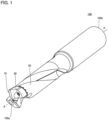
- Fig. 1 is a perspective view of drill 100. As illustrated in Fig. 1 , drill 100 is rotated about a center axis A. Drill 100 includes a tip 100a and a rear end 100b. Rear end 100b is an end opposite to tip 100a in the direction of center axis A. Tip 100a and rear end 100b are ends of drill 100 in the direction of center axis A.
- Drill 100 includes a drill head 10, a holder 20, and a fixing member 30.
- Drill head 10 is located on the side of tip 100a of drill 100.
- Holder 20 is located on the side of rear end 100b of drill 100.
- drill head 10 is made of cemented carbide.
- Fig. 2 is a perspective view of drill head 10.
- Fig. 3 is a front view of drill head 10.
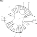
- Fig. 4 is a rear view of drill head 10.
- drill head 10 is rotated about a center axis A1.
- Center axis A1 is located on the same straight line as center axis A.
- Drill head 10 includes a mounting surface 11, a tip surface 12, and an outer peripheral surface 13.
- Mounting surface 11 and tip surface 12 are end faces of drill head 10 in the direction of center axis A1.
- Mounting surface 11 faces the side of holder 20.
- Tip surface 12 is a surface opposite to mounting surface 11 in the direction of center axis A1.
- Tip surface 12 is located at tip 100a.
- Outer peripheral surface 13 is continuous to mounting surface 11 and tip surface 12.
- a plurality of grooves 11a are formed in mounting surface 11.
- Mounting surface 11 is recessed toward tip surface 12 in groove 11a.
- Groove 11a extends from a central portion of mounting surface 11 toward outer peripheral surface 13 along the direction orthogonal to center axis A1.
- the diameter of the circumscribed circle of drill head 10 is set to an outer diameter D1.
- the circumscribed circle is indicated by a dotted line.
- outer diameter D1 is greater than or equal to 12 mm.
- Outer diameter D1 may be greater than or equal to 10 mm.
- Flute 14 is formed in a spiral shape about center axis A1 so as to reach mounting surface 11 from tip surface 12. From another point of view, flute 14 extends in a spiral shape about center axis A1 from tip surface 12 toward the side of rear end 100b.
- One of flutes 14 is located at a position symmetrical to the other flute 14 with respect to center axis A1 in the end face view viewed from the side of tip surface 12 along the direction of center axis A1.
- Drill head 10 includes two cutting edges 15.
- Cutting edge 15 extends from outer peripheral surface 13 toward center axis A1 on tip surface 12.
- Cutting edge 15 includes a main cutting edge 15a and a thinning cutting edge 15b.
- Thinning cutting edge 15b is located closer to center axis A1 than main cutting edge 15a.
- One of cutting edges 15 is located at a position symmetrical to the other cutting edge 15 with respect to center axis A1 in the end face view viewed from the side of tip surface 12 along the direction of center axis A1.
- Main cutting edges 15a includes a first end 15aa and a second end 15ab.
- First end 15aa is an end on the side of outer peripheral surface 13.
- Second end 15ab is an end opposite to first end 15aa.
- Main cutting edge 15a is continuous to thinning cutting edge 15b at second end 15ab.
- Main cutting edge 15a extends substantially linearly in the end face view viewed from the side of tip surface 12 along the direction of center axis A1.
- thinning cutting edge 15b extends linearly in the end face view viewed from the side of tip surface 12 along the direction of center axis A1.
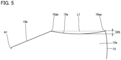
- Fig. 5 is a schematic diagram illustrating a concave amount of main cutting edge 15a.
- Fig. 5 illustrates a shape of main cutting edge 15a when tip surface 12 is viewed in the direction from tip 100a toward rear end 100b.
- the direction substantially perpendicular to main cutting edge 15a is illustrated in an enlarged manner as compared with the direction substantially parallel to main cutting edge 15a.
- a virtual straight line connecting first end 15aa and second end 15ab is set to a virtual straight line L1.
- a distance between virtual straight line L1 and main cutting edge 15a is set to a distance DIS.
- the maximum value of distance DIS is a concave amount of main cutting edge 15a with respect to virtual straight line L1.
- the concave amount of main cutting edge 15a with respect to virtual straight line L1 is greater than or equal to -0.01 times and less than or equal to 0.02 times outer diameter D1.
- the concave amount of main cutting edge 15a with respect to virtual straight line L1 is greater than or equal to 0.00 times and less than or equal to 0.01 times outer diameter D1.
- main cutting edge 15a protrudes with respect to straight line L the concave amount of main cutting edge 15a becomes a negative value.
- main cutting edge 15a is recessed from straight line L, the concave amount of main cutting edge 15a becomes a positive value.
- the concave amount of main cutting edge 15a with respect to virtual straight line L1 in Fig. 5 is the positive value.
- Fig. 6 is a schematic diagram illustrating a radial rake angle ⁇ 1 of main cutting edge 15a.
- Fig. 6 illustrates the shape of main cutting edge 15a when tip surface 12 is viewed in the direction from tip 100a toward rear end 100b.
- the direction substantially perpendicular to main cutting edge 15a is illustrated in an enlarged manner as compared with the direction substantially parallel to main cutting edge 15a.
- a specific position on main cutting edge 15a is set to a position P1.
- a virtual straight line connecting center axis A1 and position P1 is set to a virtual straight line L2.
- An angle formed by a tangent line of main cutting edge 15a at position P1 and virtual straight line L2 is radial rake angle ⁇ 1 of main cutting edge 15a.
- the difference between the maximum value and the minimum value of radial rake angle ⁇ 1 of main cutting edge 15a is preferably less than or equal to 20°.
- tip surface 12 includes two first flank surfaces 12a and two second flank surfaces 12b.
- First flank surface 12a is continuous to cutting edge 15 (main cutting edge 15a and thinning cutting edge 15b).
- One of first flank surfaces 12a is located at the position symmetrical to other first flank surface 12a with respect to center axis A1.
- Flute 14 is continuous to main cutting edge 15a from the side opposite to first flank surface 12a. That is, main cutting edge 15a is located on the ridgeline between first flank surface 12a and flute 14.
- Second flank surface 12b is located on the opposite side of first flank surface 12a with flute 14 interposed therebetween.
- One of second flank surface 12b is located at the position symmetrical to the other second flank surface 12b with respect to center axis A1.
- drill head 10 includes a thinning surface 16.
- Thinning surface 16 is continuous to tip surface 12 and flute 14.
- Thinning surface 16 includes a thinning rake surface 16a and a thinning heel surface 16b.
- Thinning rake surface 16a is continuous to thinning cutting edge 15b from the side opposite to first flank surface 12a. That is, thinning cutting edge 15b is located on the ridgeline between first flank surface 12a and thinning rake surface 16a.
- Thinning heel surface 16b is continuous to second flank surface 12b.
- the ridgeline between thinning heel surface 16b and second flank surface 12b has an arc shape in the end face view viewed from the side of tip surface 12 along the direction of center axis A1,.
- the arc shape has a corresponding curvature radius when a certain arc-shaped point is determined.
- the arc shape may have substantially the same curvature radius with respect to all arc-shaped points.
- the arc shape may have different curvature radii corresponding to arc-shaped points.
- the "radius" of the arc shape means a range of values of the curvature radius corresponding to all the arc-shaped points.
- the radius of the arc shape is greater than or equal to 0.10 times and less than or equal to 0.30 times outer diameter D1.
- the radius of the arc shape is preferably greater than or equal to 0.13 times and less than or equal to 0.24 times outer diameter D1.
- the ridgeline between thinning heel surface 16b and second flank surface 12b may be divided by a through-hole 17.
- the shape of a portion of the ridgeline between thinning heel surface 16b and second flank surface 12b on the side close to center axis A1 may be an arc shape when the ridgeline between thinning heel surface 16b and second flank surface 12b is divided by through-hole 17.
- the radius of the arc shape is greater than or equal to 0.10 times and less than or equal to 0.30 times outer diameter D1.
- the radius of the arc shape is preferably greater than or equal to 0.13 times and less than or equal to 0.24 times outer diameter D1.
- Fig. 7 is a sectional view taken along a line VII-VII in Fig. 3 .
- Fig. 7 illustrates a section of drill head 10 parallel to thinning rake surface 16a.
- an angle formed by thinning heel surface 16b and center axis A1 is set to an angle ⁇ 2.
- the angle ⁇ 2 is preferably greater than or equal to 28° and less than or equal to 32°.
- through-hole 17 are made in drill head 10.
- Through-hole 17 penetrates drill head 10 along the direction of center axis A1.
- One of through-holes 17 is located at the position symmetrical to the other through-hole 17 with respect to center axis A1.
- An end on the side of tip surface 12 of through-hole 17 is opened in second flank surface 12b.
- holder 20 is made of steel.
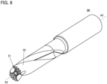
- Fig. 8 is a perspective view of holder 20.
- Fig. 9 is a front view of holder 20. As illustrated in Figs. 8 and 9 , holder 20 is rotated about center axis A2. Center axis A2 is located on the same straight line as center axis A1.
- Holder 20 includes a mounting surface 21 and an outer peripheral surface 22. Mounting surface 21 is an end face of holder 20 in the direction of center axis A2, and faces the side of drill head 10. Outer peripheral surface 22 is continuous to mounting surface 21.
- a plurality of protruding strips 21a are formed on mounting surface 21.
- Mounting surface 21 protrudes toward the side of drill head 10 at protruding strip 21a.
- Protruding strip 21a extends from the central portion of mounting surface 21 toward outer peripheral surface 22 along the direction orthogonal to center axis A2.
- Two screw holes 21b are made in mounting surface 21. Screw hole 21b extends from mounting surface 21 toward the side of rear end 100b. One of screw holes 21b is located at the position symmetrical to the other screw hole 21b with respect to center axis A2.
- Protruding strip 21a is fitted into groove 11a.
- screw hole 21b is located at the position overlapping through-hole 17.
- fixing member 30 is a screw. Fixing member 30 is inserted into through-hole 17 and then screwed into screw hole 21b, thereby fastening drill head 10 to holder 20. In this manner, holder 20 is attached to drill head 10 (mounting surface 11).
- the chips When cutting is performed with drill 100, the chips are generated from a work material by cutting edge 15.
- the chip portion generated by thinning cutting edge 15b comes into contact with thinning heel surface 16b and is curved when being moved toward flute 14.
- a crack is generated in the chip portion generated by thinning cutting edge 15b.
- the crack generated in the chip develops to the chip portion generated by main cutting edge 15a by centrifugal force of the chip, and breaks the chip.
- main cutting edge 15a extends substantially linearly. That is, in drill 100, the concave amount of main cutting edge 15a with respect to virtual straight line L1 is greater than or equal to -0.01 times and less than or equal to 0.02 times outer diameter D1. Consequently, in drill 100, the chip portion generated by main cutting edge 15a has small distortion, and the crack generated in the chip portion generated by thinning cutting edge 15b easily develops to the chip portion generated by main cutting edge 15a.
- the chip portion generated by thinning cutting edge 15b is hardly curved by thinning heel surface 16b, so that the crack is hardly generated in the chip portion generated by thinning cutting edge 15b.
- the ridgeline between thinning heel surface 16b and second flank surface 12b has an arc shape having a radius of greater than or equal to 0.10 times and less than or equal to 0.30 times outer diameter D1. Consequently, in drill 100, the chip portion generated by thinning cutting edge 15b is easily curved by thinning heel surface 16b, so that the crack is easily generated in the chip portion generated by thinning cutting edge 15b.
- the crack is easily generated in the chip portion generated by thinning cutting edge 15b, and the generated crack easily develops to the chip portion generated by main cutting edge 15a, so that the chips are easy to divide.
- the chips are more easily divided. In this case, stability of cutting can be enhanced.
- the radius of the ridgeline between arc-shaped thinning heel surface 16b and second flank surface 12b is greater than or equal to 0.13 times and less than or equal to 0.24 times outer diameter D1, the chips are more easily divided.
- thinning cutting edge 15b extends linearly in the end face view viewed from the side of tip surface 12 along the direction of center axis A1
- the distortion of the chip portion generated by thinning cutting edge 15b is reduced, and the generated crack easily develops in the chip portion generated by thinning cutting edge 15b. Accordingly, in this case, the chips are more easily divided.
- a first cutting test, a second cutting test, and a third cutting test were performed in order to check the effect of drill 100.
- drills 100 of sample numbers 1-1 to 1-7 were used.
- the radius of the ridgeline between arc-shaped thinning heel surface 16b and second flank surface 12b was set to 0.20 times outer diameter D1, and angle ⁇ 2 was set to 30°.
- the concave amount of main cutting edge 15a with respect to virtual straight line L1 was changed within a range of greater than or equal to -0.01 times and less than or equal to 0.06 times outer diameter D1.
- drills 100 of sample numbers 2-1 to 2-8 were used.
- the concave amount of main cutting edge 15a with respect to virtual straight line L1 was set to 0.00 times outer diameter D1
- angle ⁇ 2 was set to 30°.
- the radius of the ridgeline between arc-shaped thinning heel surface 16b and second flank surface 12b was changed within a range of greater than or equal to 0.10 times and less than or equal to 0.40 times outer diameter D1.
- Fig. 10 is a graph illustrating a result of the first cutting test.
- a horizontal axis in Fig. 10 is a value obtained by dividing the concave amount of main cutting edge 15a with respect to virtual straight line L1 by outer diameter D1
- a vertical axis in Fig. 10 is the chip division ratio (unit: percent).
- the chip division ratio is a value obtained by dividing a weight of the chip divided by one curl by a total weight of the generated chips.
- Fig. 11 is a graph illustrating a result of the second cutting test.
- the horizontal axis in Fig. 11 is a value obtained by dividing the radius of the ridgeline between arc-shaped thinning heel surface 16b and second flank surface 12b by outer diameter D1, and the vertical axis in Fig. 11 is the chip division ratio.
- the chips are easily divided when the concave amount of main cutting edge 15a with respect to virtual straight line L1 falls within the range of greater than or equal to -0.01 times and less than or equal to 0.02 times outer diameter D1, and when the radius of the ridgeline between arc-shaped thinning heel surface 16b and second flank surface 12b falls within the range of greater than or equal to 0.10 times and less than or equal to 0.30 times outer diameter D1.
- drills 100 of sample numbers 3-1 to 3-7 were used.
- the concave amount of main cutting edge 15a with respect to virtual straight line L1 was set to 0.00 times outer diameter D1
- the radius of the ridgeline between arcuate thinning heel surface 16b and second flank surface 12b was set to 0.20 times outer diameter D1.
- angle ⁇ 2 was changed within the range of greater than or equal to 25° and less than or equal to 45°.
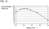
- Fig. 12 is a graph illustrating a result of the third cutting test.
- the horizontal axis in Fig. 12 represents angle ⁇ 2 (unit: °).
- the vertical axis represents the chip division ratio (unit: percent).
- the chip division ratio became greater than or equal to 82%. From this, it has been experimentally found that the chips were more easily divided when angle ⁇ 2 fell within the range of greater than or equal to 28° and less than or equal to 32°.
- drill 100 may be a solid drill. That is, drill 100 may not be divided into drill head 10 and holder 20.
- 10 drill head, 11: mounting surface, 11a: groove, 12: tip surface, 12a: first flank surface, 12b: second flank surface, 13: outer peripheral surface, 14: flute, 15: cutting edge, 15a: main cutting edge, 15aa: first end, 15ab: second end, 15b: thinning cutting edge, 16: thinning surface, 16a: thinning rake surface, 16b: thinning heel surface, 17: through-hole, 20: holder, 21: mounting surface, 21a: protruding strip, 21b: screw hole, 22: outer peripheral surface, 30: fixing member, 100: drill, 100a: distal end, 100b: rear end, A, A1, A2: center axis, D1, D2: outer diameter, DIS: distance, L: straight line, L1, L2: virtual straight line, P1: position, ⁇ 1: radial rake angle, ⁇ 2: angle
Landscapes
- Engineering & Computer Science (AREA)
- Mechanical Engineering (AREA)
- Drilling Tools (AREA)
Abstract
Description
- The present disclosure relates to a drill head, a tip exchangeable drill, and a drill.
-
WO 2019/049257 (PTL 1) describes a drill. The drill described in PTL 1 is rotated about an axis. The drill described in Patent Literature 1 includes an outer peripheral surface, a discharge flute, a first flank surface, a second flank surface, a cutting edge, a thinning edge, and a gash. - A discharge flute is formed on the outer peripheral surface. The discharge flute extends spirally around the axis from a tip side of the drill toward a rear end side of the drill. The discharge flute includes an inner surface facing a rotation direction side of the drill. The cutting edge is provided on a ridgeline between the inner surface of the discharge flute and the first flank surface. The second flank surface is opposite to the first flank surface with the discharge flute interposed therebetween. The thinning edge extends from the inner end of the cutting edge toward a chisel. The gash is connected to the discharge flute.
- The gash includes a thinning surface continuous to the thinning edge from a side opposite to the first flank surface and a gash surface continuous to the second flank surface. The ridgeline between the gash surface and the second flank surface has an arc shape in an end face view seen along the direction of the axis from the tip side of the drill.
- PTL 1:
WO 2019/049257 - A drill head of the present disclosure is rotated about a center axis. The drill head includes: a mounting surface that is an end face in a direction of the center axis; a tip surface that is an opposite surface to the mounting surface in the direction of the center axis; an outer peripheral surface continuous to the mounting surface and the tip surface; a cutting edge extending from the outer peripheral surface toward the center axis in the tip surface; a flute that is formed on the outer peripheral surface and extends spirally around the center axis from the tip surface to the mounting surface; and a thinning surface continuous to the tip surface and the flute. The tip surface includes: a first flank surface continuous to the cutting edge; and a second flank surface located on a side opposite to the first flank surface with the flute interposed therebetween. The cutting edge includes: a main cutting edge continuous to the outer peripheral surface; and a thinning cutting edge that is continuous to the main cutting edge and is located closer to the center axis than the main cutting edge. The main cutting edge includes: a first end that is an end on a side of the outer peripheral surface; and a second end that is an end on a side of the thinning cutting edge. The thinning surface includes: a thinning rake surface continuous to the thinning cutting edge from a side opposite to the first flank surface; and a thinning heel surface continuous to the second flank surface. A concave amount of the main cutting edge with respect to a virtual straight line connecting the first end and the second end is greater than or equal to -0.01 times and less than or equal to 0.02 times a diameter of a circumscribed circle of the drill head in an end face view viewed from a tip surface side along the direction of the center axis. A ridgeline between the thinning heel surface and the second flank surface has an arc shape having a radius of greater than or equal to 0.10 times and less than or equal to 0.30 times the diameter in the end face view.
-
-
Fig. 1 is a perspective view of adrill 100. -
Fig. 2 is a perspective view of adrill head 10. -
Fig. 3 is a front view of thedrill head 10. -
Fig. 4 is a rear view of thedrill head 10. -
Fig. 5 is a schematic diagram illustrating a concave amount of amain cutting edge 15a. -
Fig. 6 is a schematic diagram illustrating a radial rake angle θ1 of themain cutting edge 15a. -
Fig. 7 is a sectional view taken along a line VII-VII inFig. 3 . -
Fig. 8 is a perspective view of aholder 20. -
Fig. 9 is a front view of theholder 20. -
Fig. 10 is a graph illustrating a result of a first cutting test. -
Fig. 11 is a graph illustrating a result of a second cutting test. -
Fig. 12 is a graph illustrating a result of a third cutting test. - In the drill described in PTL 1, the cutting edge extends in an arc shape in the end face view viewed along the direction of the axial center from the tip side of the drill. Accordingly, in the drill described in PTL 1, chips cut out of the cutting edge is curved and hardly divided.
- The present disclosure has been made in view of the above-described problems of the prior art. More specifically, the present disclosure provides a drill head in which the chips are easily divided.
- According to the drill head of the present disclosure, the chips are easily divided.
- First, an embodiment of the present disclosure will be listed and described.
- (1) A drill head according to the embodiment is rotated about a center axis. The drill head includes: a mounting surface that is an end face in a direction of the center axis; a tip surface that is an opposite surface to the mounting surface in the direction of the center axis; an outer peripheral surface continuous to the mounting surface and the tip surface; a cutting edge extending from the outer peripheral surface toward the center axis in the tip surface; a flute that is formed on the outer peripheral surface and extends spirally around the center axis from the tip surface to the mounting surface; and a thinning surface continuous to the tip surface and the flute. The tip surface includes: a first flank surface continuous to the cutting edge; and a second flank surface located on a side opposite to the first flank surface with the flute interposed therebetween. The cutting edge includes: a main cutting edge continuous to the outer peripheral surface; and a thinning cutting edge that is continuous to the main cutting edge and is located closer to the center axis than the main cutting edge. The main cutting edge includes: a first end that is an end on a side of the outer peripheral surface; and a second end that is an end on a side of the thinning cutting edge. The thinning surface includes: a thinning rake surface continuous to the thinning cutting edge from a side opposite to the first flank surface; and a thinning heel surface continuous to the second flank surface. A concave amount of the main cutting edge with respect to a virtual straight line connecting the first end and the second end is greater than or equal to -0.01 times and less than or equal to 0.02 times a diameter of a circumscribed circle of the drill head in an end face view viewed from a tip surface side along the direction of the center axis. A ridgeline between the thinning heel surface and the second flank surface has an arc shape having a radius of greater than or equal to 0.10 times and less than or equal to 0.30 times the diameter in the end face view.
- According to the drill head of (1), the chips are easily divided.
- (2) In the drill head of (1), the concave amount of the main cutting edge with respect to the virtual straight line connecting the first end and the second end is greater than or equal to 0.00 times and less than or equal to 0.01 times a diameter of the drill head in the end face view viewed from the tip surface side along the direction of the center axis.
- According to the drill head of (2), the chips are further easily divided, and the stability of cutting is enhanced.
- (3) In the drill head of (1) or (2), the radius of the ridgeline between the arc-shaped thinning heel surface and the second flank surface may be greater than or equal to 0.13 times and less than or equal to 0.24 times the diameter of the drill head.
- According to the drill head of (3), the chips are more easily divided.
- (4) In the drill heads of (1) to (3), the difference between the maximum value and the minimum value of the radial rake angle of the main cutting edge may be less than or equal to 20°.
- (5) In the drill heads of (1) to (4), the angle between the direction of the center axis and the thinning heel surface may be greater than or equal to 28° and less than or equal to 32°.
- According to the drill head of (5), the chips are more easily divided.
- (6) In the drill heads of (1) to (5), the thinning cutting edge may extend linearly in the end face view viewed from the tip surface side along the direction of the center axis.
- According to the drill head of (6), the chips are more easily divided.
- (7) A tip exchangeable drill according to an embodiment includes the drill heads of (1) to (6) and a holder attached to a mounting surface.
- (8) The drill according to the embodiment is rotated about the center axis. The drill includes: a tip and a rear end that are ends in a direction of the center axis; a tip surface that is located at the tip; an outer peripheral surface continuous to the mounting surface and the tip surface; a cutting edge extending from the outer peripheral surface toward the center axis in the tip surface; a flute that is formed on the outer peripheral surface and extends spirally around the center axis from the tip surface toward a rear end surface; and a thinning surface continuous to the tip surface and the flute. The tip surface includes: a first flank surface continuous to the cutting edge; and a second flank surface located on a side opposite to the first flank surface with the flute interposed therebetween. The cutting edge includes: a main cutting edge continuous to the outer peripheral surface; and a thinning cutting edge that is continuous to the main cutting edge and is located closer to the center axis than the main cutting edge. The main cutting edge includes: a first end that is an end on a side of the outer peripheral surface; and a second end that is an end on a side of the thinning cutting edge. The thinning surface includes: a thinning rake surface continuous to the thinning cutting edge from a side opposite to the first flank surface; and a thinning heel surface continuous to the second flank surface. A concave amount of the main cutting edge with respect to a virtual straight line connecting the first end and the second end is greater than or equal to -0.01 times and less than or equal to 0.02 times a diameter of a circumscribed circle of the drill in an end face view viewed from a tip surface side along the direction of the center axis. A ridgeline between the thinning heel surface and the second flank surface has an arc shape having a radius of greater than or equal to 0.10 times and less than or equal to 0.30 times the diameter in the end face view.
- According to the drill of (8), the chips are easily divided.
[Detailed Embodiments of the Present Disclosure] With reference to the drawings, an embodiment of the present disclosure will be described in detail. In the following drawings, the same or corresponding component is designated by the same reference numeral, and the overlapping description will be omitted. - A drill (hereinafter referred to as a "
drill 100") according to an embodiment will be described.Drill 100 is a tip exchangeable drill. - A configuration of
drill 100 will be described below. -
Fig. 1 is a perspective view ofdrill 100. As illustrated inFig. 1 ,drill 100 is rotated about a centeraxis A. Drill 100 includes atip 100a and arear end 100b.Rear end 100b is an end opposite to tip 100a in the direction of centeraxis A. Tip 100a andrear end 100b are ends ofdrill 100 in the direction of center axis A. -
Drill 100 includes adrill head 10, aholder 20, and a fixingmember 30.Drill head 10 is located on the side oftip 100a ofdrill 100.Holder 20 is located on the side ofrear end 100b ofdrill 100. - For example,
drill head 10 is made of cemented carbide.Fig. 2 is a perspective view ofdrill head 10.Fig. 3 is a front view ofdrill head 10.Fig. 4 is a rear view ofdrill head 10. As illustrated inFigs. 2 ,3 , and4 ,drill head 10 is rotated about a center axis A1. Center axis A1 is located on the same straight line as center axis A. -
Drill head 10 includes a mountingsurface 11, atip surface 12, and an outerperipheral surface 13. Mountingsurface 11 andtip surface 12 are end faces ofdrill head 10 in the direction of center axis A1. Mountingsurface 11 faces the side ofholder 20.Tip surface 12 is a surface opposite to mountingsurface 11 in the direction of center axis A1.Tip surface 12 is located attip 100a. Outerperipheral surface 13 is continuous to mountingsurface 11 andtip surface 12. - A plurality of
grooves 11a are formed in mountingsurface 11. Mountingsurface 11 is recessed towardtip surface 12 ingroove 11a.Groove 11a extends from a central portion of mountingsurface 11 toward outerperipheral surface 13 along the direction orthogonal to center axis A1. - In the end face view viewed from the side of
tip surface 12 along the direction of center axis A1, the diameter of the circumscribed circle ofdrill head 10 is set to an outer diameter D1. InFig. 3 , the circumscribed circle is indicated by a dotted line. For example, outer diameter D1 is greater than or equal to 12 mm. Outer diameter D1 may be greater than or equal to 10 mm. - Two
flutes 14 are formed on outerperipheral surface 13.Flute 14 is formed in a spiral shape about center axis A1 so as to reach mountingsurface 11 fromtip surface 12. From another point of view,flute 14 extends in a spiral shape about center axis A1 fromtip surface 12 toward the side ofrear end 100b. One offlutes 14 is located at a position symmetrical to theother flute 14 with respect to center axis A1 in the end face view viewed from the side oftip surface 12 along the direction of center axis A1. -
Drill head 10 includes two cutting edges 15. Cuttingedge 15 extends from outerperipheral surface 13 toward center axis A1 ontip surface 12. Cuttingedge 15 includes amain cutting edge 15a and a thinningcutting edge 15b. Thinningcutting edge 15b is located closer to center axis A1 thanmain cutting edge 15a. One of cuttingedges 15 is located at a position symmetrical to theother cutting edge 15 with respect to center axis A1 in the end face view viewed from the side oftip surface 12 along the direction of center axis A1. -
Main cutting edges 15a includes a first end 15aa and a second end 15ab. First end 15aa is an end on the side of outerperipheral surface 13. Second end 15ab is an end opposite to first end 15aa.Main cutting edge 15a is continuous to thinningcutting edge 15b at second end 15ab.Main cutting edge 15a extends substantially linearly in the end face view viewed from the side oftip surface 12 along the direction of center axis A1. Preferably, thinningcutting edge 15b extends linearly in the end face view viewed from the side oftip surface 12 along the direction of center axis A1. -
Fig. 5 is a schematic diagram illustrating a concave amount ofmain cutting edge 15a.Fig. 5 illustrates a shape ofmain cutting edge 15a whentip surface 12 is viewed in the direction fromtip 100a towardrear end 100b. InFig. 5 , the direction substantially perpendicular tomain cutting edge 15a is illustrated in an enlarged manner as compared with the direction substantially parallel tomain cutting edge 15a. As illustrated inFig. 5 , a virtual straight line connecting first end 15aa and second end 15ab is set to a virtual straight line L1. A distance between virtual straight line L1 andmain cutting edge 15a is set to a distance DIS. The maximum value of distance DIS is a concave amount ofmain cutting edge 15a with respect to virtual straight line L1. - The concave amount of
main cutting edge 15a with respect to virtual straight line L1 is greater than or equal to -0.01 times and less than or equal to 0.02 times outer diameter D1. Preferably, the concave amount ofmain cutting edge 15a with respect to virtual straight line L1 is greater than or equal to 0.00 times and less than or equal to 0.01 times outer diameter D1. Whenmain cutting edge 15a protrudes with respect to straight line L, the concave amount ofmain cutting edge 15a becomes a negative value. Whenmain cutting edge 15a is recessed from straight line L, the concave amount ofmain cutting edge 15a becomes a positive value. The concave amount ofmain cutting edge 15a with respect to virtual straight line L1 inFig. 5 is the positive value. -
Fig. 6 is a schematic diagram illustrating a radial rake angle θ1 ofmain cutting edge 15a.Fig. 6 illustrates the shape ofmain cutting edge 15a whentip surface 12 is viewed in the direction fromtip 100a towardrear end 100b. InFig. 6 , the direction substantially perpendicular tomain cutting edge 15a is illustrated in an enlarged manner as compared with the direction substantially parallel tomain cutting edge 15a. As illustrated inFig. 6 , a specific position onmain cutting edge 15a is set to a position P1. A virtual straight line connecting center axis A1 and position P1 is set to a virtual straight line L2. An angle formed by a tangent line ofmain cutting edge 15a at position P1 and virtual straight line L2 is radial rake angle θ1 ofmain cutting edge 15a. The difference between the maximum value and the minimum value of radial rake angle θ1 ofmain cutting edge 15a is preferably less than or equal to 20°. - As illustrated in
Fig. 3 ,tip surface 12 includes two first flank surfaces 12a and two second flank surfaces 12b.First flank surface 12a is continuous to cutting edge 15 (main cutting edge 15a and thinningcutting edge 15b). One offirst flank surfaces 12a is located at the position symmetrical to otherfirst flank surface 12a with respect to center axis A1.Flute 14 is continuous tomain cutting edge 15a from the side opposite tofirst flank surface 12a. That is,main cutting edge 15a is located on the ridgeline betweenfirst flank surface 12a andflute 14.Second flank surface 12b is located on the opposite side offirst flank surface 12a withflute 14 interposed therebetween. One ofsecond flank surface 12b is located at the position symmetrical to the othersecond flank surface 12b with respect to center axis A1. - As illustrated in
Fig. 2 ,drill head 10 includes a thinningsurface 16. Thinningsurface 16 is continuous to tipsurface 12 andflute 14. Thinningsurface 16 includes a thinningrake surface 16a and a thinningheel surface 16b. - Thinning
rake surface 16a is continuous to thinningcutting edge 15b from the side opposite tofirst flank surface 12a. That is, thinningcutting edge 15b is located on the ridgeline betweenfirst flank surface 12a and thinningrake surface 16a. Thinningheel surface 16b is continuous tosecond flank surface 12b. As illustrated inFig. 3 , the ridgeline between thinningheel surface 16b andsecond flank surface 12b has an arc shape in the end face view viewed from the side oftip surface 12 along the direction of center axis A1,. The arc shape has a corresponding curvature radius when a certain arc-shaped point is determined. The arc shape may have substantially the same curvature radius with respect to all arc-shaped points. The arc shape may have different curvature radii corresponding to arc-shaped points. In the present specification, the "radius" of the arc shape means a range of values of the curvature radius corresponding to all the arc-shaped points. The radius of the arc shape is greater than or equal to 0.10 times and less than or equal to 0.30 times outer diameter D1. The radius of the arc shape is preferably greater than or equal to 0.13 times and less than or equal to 0.24 times outer diameter D1. The ridgeline between thinningheel surface 16b andsecond flank surface 12b may be divided by a through-hole 17. The shape of a portion of the ridgeline between thinningheel surface 16b andsecond flank surface 12b on the side close to center axis A1 may be an arc shape when the ridgeline between thinningheel surface 16b andsecond flank surface 12b is divided by through-hole 17. The radius of the arc shape is greater than or equal to 0.10 times and less than or equal to 0.30 times outer diameter D1. The radius of the arc shape is preferably greater than or equal to 0.13 times and less than or equal to 0.24 times outer diameter D1. -
Fig. 7 is a sectional view taken along a line VII-VII inFig. 3 .Fig. 7 illustrates a section ofdrill head 10 parallel to thinningrake surface 16a. As illustrated inFig. 7 , an angle formed by thinningheel surface 16b and center axis A1 is set to an angle θ2. The angle θ2 is preferably greater than or equal to 28° and less than or equal to 32°. - As illustrated in
Figs. 3 and4 , two through-holes 17 are made indrill head 10. Through-hole 17 penetratesdrill head 10 along the direction of center axis A1. One of through-holes 17 is located at the position symmetrical to the other through-hole 17 with respect to center axis A1. An end on the side oftip surface 12 of through-hole 17 is opened insecond flank surface 12b. - For example,
holder 20 is made of steel.Fig. 8 is a perspective view ofholder 20.Fig. 9 is a front view ofholder 20. As illustrated inFigs. 8 and9 ,holder 20 is rotated about center axis A2. Center axis A2 is located on the same straight line as center axis A1.Holder 20 includes a mountingsurface 21 and an outerperipheral surface 22. Mountingsurface 21 is an end face ofholder 20 in the direction of center axis A2, and faces the side ofdrill head 10. Outerperipheral surface 22 is continuous to mountingsurface 21. - A plurality of protruding
strips 21a are formed on mountingsurface 21. Mountingsurface 21 protrudes toward the side ofdrill head 10 at protrudingstrip 21a.Protruding strip 21a extends from the central portion of mountingsurface 21 toward outerperipheral surface 22 along the direction orthogonal to center axis A2. Twoscrew holes 21b are made in mountingsurface 21.Screw hole 21b extends from mountingsurface 21 toward the side ofrear end 100b. One ofscrew holes 21b is located at the position symmetrical to theother screw hole 21b with respect to center axis A2. -
Protruding strip 21a is fitted intogroove 11a. In a state where protrudingstrip 21a is fitted intogroove 11a,screw hole 21b is located at the position overlapping through-hole 17. For example, fixingmember 30 is a screw. Fixingmember 30 is inserted into through-hole 17 and then screwed intoscrew hole 21b, thereby fasteningdrill head 10 toholder 20. In this manner,holder 20 is attached to drill head 10 (mounting surface 11). - Effects of the
drill 100 will be described below. - When cutting is performed with
drill 100, the chips are generated from a work material by cuttingedge 15. The chip portion generated by thinningcutting edge 15b comes into contact with thinningheel surface 16b and is curved when being moved towardflute 14. When the curvature reaches the limit, a crack is generated in the chip portion generated by thinningcutting edge 15b. The crack generated in the chip develops to the chip portion generated bymain cutting edge 15a by centrifugal force of the chip, and breaks the chip. - In
drill 100,main cutting edge 15a extends substantially linearly. That is, indrill 100, the concave amount ofmain cutting edge 15a with respect to virtual straight line L1 is greater than or equal to -0.01 times and less than or equal to 0.02 times outer diameter D1. Consequently, indrill 100, the chip portion generated bymain cutting edge 15a has small distortion, and the crack generated in the chip portion generated by thinningcutting edge 15b easily develops to the chip portion generated bymain cutting edge 15a. - When the ridgeline between thinning
heel surface 16b andsecond flank surface 12b is linear in the end face view viewed from the side oftip surface 12 along the direction of center axis A1, the chip portion generated by thinningcutting edge 15b is hardly curved by thinningheel surface 16b, so that the crack is hardly generated in the chip portion generated by thinningcutting edge 15b. - However, in
drill 100, the ridgeline between thinningheel surface 16b andsecond flank surface 12b has an arc shape having a radius of greater than or equal to 0.10 times and less than or equal to 0.30 times outer diameter D1. Consequently, indrill 100, the chip portion generated by thinningcutting edge 15b is easily curved by thinningheel surface 16b, so that the crack is easily generated in the chip portion generated by thinningcutting edge 15b. - As described above, in
drill 100, the crack is easily generated in the chip portion generated by thinningcutting edge 15b, and the generated crack easily develops to the chip portion generated bymain cutting edge 15a, so that the chips are easy to divide. - When the concave amount of
main cutting edge 15a with respect to virtual straight line L1 is greater than or equal to 0.00 times and less than or equal to 0.01 times outer diameter D1, the chips are more easily divided. In this case, stability of cutting can be enhanced. When the radius of the ridgeline between arc-shaped thinningheel surface 16b andsecond flank surface 12b is greater than or equal to 0.13 times and less than or equal to 0.24 times outer diameter D1, the chips are more easily divided. - In the case of large angle θ2, the chips stagnate within the thinning, so that there is a possibility that the crack is hardly generated in the chip portion generated by thinning
cutting edge 15b. On the other hand, in the case of small angle θ2, the chip portion generated by thinningcutting edge 15b is hardly curved due to the contact with thinningheel surface 16b (the crack is hardly generated). Consequently, the chips are more easily divided by optimizing the range of angle θ2 (more specifically, angle θ2 is set to greater than or equal to 28° and less than or equal to 32°). - When thinning
cutting edge 15b extends linearly in the end face view viewed from the side oftip surface 12 along the direction of center axis A1, the distortion of the chip portion generated by thinningcutting edge 15b is reduced, and the generated crack easily develops in the chip portion generated by thinningcutting edge 15b. Accordingly, in this case, the chips are more easily divided. - A first cutting test, a second cutting test, and a third cutting test were performed in order to check the effect of
drill 100. - In the first cutting test, drills 100 of sample numbers 1-1 to 1-7 were used. In the first cutting test, the radius of the ridgeline between arc-shaped thinning
heel surface 16b andsecond flank surface 12b was set to 0.20 times outer diameter D1, and angle θ2 was set to 30°. In the first cutting test, the concave amount ofmain cutting edge 15a with respect to virtual straight line L1 was changed within a range of greater than or equal to -0.01 times and less than or equal to 0.06 times outer diameter D1. -
Table 1 Sample number 1-1 1-2 1-3 1-4 1-5 1-6 1-7 Concave amount of main cutting edge 15a/outer diameter D1 with respect to virtual straight line L1-0.01 0.00 0.01 0.02 0.03 0.04 0.06 Chip division ratio (%) 53 80 77 60 35 24 20 - In the second cutting test, drills 100 of sample numbers 2-1 to 2-8 were used. In the second cutting test, the concave amount of
main cutting edge 15a with respect to virtual straight line L1 was set to 0.00 times outer diameter D1, and angle θ2 was set to 30°. In the second cutting test, the radius of the ridgeline between arc-shaped thinningheel surface 16b andsecond flank surface 12b was changed within a range of greater than or equal to 0.10 times and less than or equal to 0.40 times outer diameter D1. -
Table 2 Sample number 2-1 2-2 2-3 2-4 2-5 2-6 2-7 2-8 Radius/outer diameter D1 of ridgeline between arc-shaped thinning heel surface 16b andsecond flank surface 12b0.10 0.13 0.15 0.20 0.24 0.25 0.30 0.40 Chip division ratio (%) 70 80 82 83 80 71 51 30 -
Fig. 10 is a graph illustrating a result of the first cutting test. A horizontal axis inFig. 10 is a value obtained by dividing the concave amount ofmain cutting edge 15a with respect to virtual straight line L1 by outer diameter D1, and a vertical axis inFig. 10 is the chip division ratio (unit: percent). The chip division ratio is a value obtained by dividing a weight of the chip divided by one curl by a total weight of the generated chips. -
Fig. 11 is a graph illustrating a result of the second cutting test. The horizontal axis inFig. 11 is a value obtained by dividing the radius of the ridgeline between arc-shaped thinningheel surface 16b andsecond flank surface 12b by outer diameter D1, and the vertical axis inFig. 11 is the chip division ratio. - As illustrated in
Fig. 10 , when the concave amount ofmain cutting edge 15a with respect to virtual straight line L1 fell within the range of greater than or equal to - 0.01 times and less than or equal to 0.02 times outer diameter D1, the chip division ratio was greater than or equal to 50%. On the other hand, when the concave amount ofmain cutting edge 15a with respect to virtual straight line L1 fell within the range of greater than or equal to 0.03 times, the chip division ratio was less than 50%. - As illustrated in
Fig. 11 , when the radius of the ridgeline between arc-shaped thinningheel surface 16b andsecond flank surface 12b fell within the range of greater than or equal to 0.10 times and less than or equal to 0.30 times outer diameter D1, the chip division ratio was greater than or equal to 50%. On the other hand, when the radius of the ridgeline between arc-shaped thinningheel surface 16b andsecond flank surface 12b fell within the range of greater than or equal to 0.35 times outer diameter D1, the chip division ratio was less than 50%. - From the above comparison, it has been experimentally found that the chips are easily divided when the concave amount of
main cutting edge 15a with respect to virtual straight line L1 falls within the range of greater than or equal to -0.01 times and less than or equal to 0.02 times outer diameter D1, and when the radius of the ridgeline between arc-shaped thinningheel surface 16b andsecond flank surface 12b falls within the range of greater than or equal to 0.10 times and less than or equal to 0.30 times outer diameter D1. - When the concave amount of
main cutting edge 15a with respect to virtual straight line L1 fell within the range of greater than or equal to 0.00 times and less than or equal to 0.01 times outer diameter D1, the chip division ratio became greater than or equal to 77%. From this, it has been experimentally found that the chips are further easily divided when the concave amount ofmain cutting edge 15a with respect to virtual straight line L1 fell within the range of greater than or equal to 0.00 times and less than or equal to 0.01 times outer diameter D1. - When the radius of the ridgeline between arc-shaped thinning
heel surface 16b andsecond flank surface 12b fell within the range of greater than or equal to 0.13 times and less than or equal to 0.24 times outer diameter D1, the chip division ratio became greater than or equal to 80%. From this, it has been experimentally found that the chips are further easily divided when the radius of the ridgeline between arc-shaped thinningheel surface 16b andsecond flank surface 12b fell within the range of greater than or equal to 0.13 times and less than or equal to 0.24 times outer diameter D1. - In the third cutting test, drills 100 of sample numbers 3-1 to 3-7 were used. In the third cutting test, the concave amount of
main cutting edge 15a with respect to virtual straight line L1 was set to 0.00 times outer diameter D1, and the radius of the ridgeline between arcuate thinningheel surface 16b andsecond flank surface 12b was set to 0.20 times outer diameter D1. In the third cutting test, angle θ2 was changed within the range of greater than or equal to 25° and less than or equal to 45°. -
Table 3 Sample number 3-1 3-2 3-3 3-4 3-5 3-6 3-7 Angle θ2 (°) 25 28 30 32 34 38 45 Chip division ratio (%) 65 82 86 83 78 63 20 -
Fig. 12 is a graph illustrating a result of the third cutting test. The horizontal axis inFig. 12 represents angle θ2 (unit: °). InFig. 12 , the vertical axis represents the chip division ratio (unit: percent). As illustrated inFig. 12 , when angle θ2 fell within the range of greater than or equal to 28° and less than or equal to 32°, the chip division ratio became greater than or equal to 82%. From this, it has been experimentally found that the chips were more easily divided when angle θ2 fell within the range of greater than or equal to 28° and less than or equal to 32°. - Although the example in which drill 100 is the cutting edge exchangeable drill has been described above, drill 100 may be a solid drill. That is,
drill 100 may not be divided intodrill head 10 andholder 20. - It should be understood that the embodiment disclosed herein is illustrative in all respects and are not restrictive. The scope of the present invention is defined not by the embodiment but by the claims, and is intended to include meanings equivalent to the claims and all modifications within the scope.
- 10: drill head, 11: mounting surface, 11a: groove, 12: tip surface, 12a: first flank surface, 12b: second flank surface, 13: outer peripheral surface, 14: flute, 15: cutting edge, 15a: main cutting edge, 15aa: first end, 15ab: second end, 15b: thinning cutting edge, 16: thinning surface, 16a: thinning rake surface, 16b: thinning heel surface, 17: through-hole, 20: holder, 21: mounting surface, 21a: protruding strip, 21b: screw hole, 22: outer peripheral surface, 30: fixing member, 100: drill, 100a: distal end, 100b: rear end, A, A1, A2: center axis, D1, D2: outer diameter, DIS: distance, L: straight line, L1, L2: virtual straight line, P1: position, θ1: radial rake angle, θ2: angle
Claims (8)
- A drill head rotated about a center axis, the drill head comprising:a mounting surface that is an end face in a direction of the center axis;a tip surface that is an opposite surface to the mounting surface in the direction of the center axis;an outer peripheral surface continuous to the mounting surface and the tip surface;a cutting edge extending from the outer peripheral surface toward the center axis in the tip surface;a flute that is formed on the outer peripheral surface and extends spirally around the center axis from the tip surface to the mounting surface; anda thinning surface continuous to the tip surface and the flute,wherein the tip surface includes:a first flank surface continuous to the cutting edge; anda second flank surface located on a side opposite to the first flank surface with the flute interposed therebetween,the cutting edge includes:a main cutting edge continuous to the outer peripheral surface; anda thinning cutting edge that is continuous to the main cutting edge and is located closer to the center axis than the main cutting edge,the main cutting edge includes:a first end that is an end on a side of the outer peripheral surface; anda second end that is an end on a side of the thinning cutting edge,the thinning surface includes:a thinning rake surface continuous to the thinning cutting edge from a side opposite to the first flank surface; anda thinning heel surface continuous to the second flank surface,a concave amount of the main cutting edge with respect to a virtual straight line connecting the first end and the second end is greater than or equal to -0.01 times and less than or equal to 0.02 times a diameter of a circumscribed circle of the drill head in an end face view viewed from a tip surface side along the direction of the center axis, anda ridgeline between the thinning heel surface and the second flank surface has an arc shape having a radius of greater than or equal to 0.10 times and less than or equal to 0.30 times the diameter in the end face view.
- The drill head according to claim 1, wherein the concave amount is greater than or equal to 0.00 times and less than or equal to 0.01 times the diameter in the end face view.
- The drill head according to claim 1 or 2, wherein the radius is greater than or equal to 0.13 times and less than or equal to 0.24 times the diameter.
- The drill head according to any one of claims 1 to 3, wherein a difference between a maximum value and a minimum value of a radial rake angle of the main cutting edge is less than or equal to 20°.
- The drill head according to any one of claims 1 to 4, wherein an angle between a direction of the center axis and the thinning heel surface is greater than or equal to 28° and less than or equal to 32°.
- The drill head according to any one of claims 1 to 5, wherein the thinning cutting edge extends linearly in the end face view.
- A tip exchangeable drill comprising:the drill head according to any one of claims 1 to 6; anda holder attached to the mounting surface.
- A drill rotated about a center axis, the drill comprising:a tip and a rear end that are ends in a direction of the center axis;a tip surface that is located at the tip;an outer peripheral surface continuous to the tip surface;a cutting edge extending from the outer peripheral surface toward the center axis in the tip surface;a flute that is formed on the outer peripheral surface and extends spirally around the center axis from the tip surface toward a rear end surface; anda thinning surface continuous to the tip surface and the flute,wherein the tip surface includes:a first flank surface continuous to the cutting edge; anda second flank surface located on a side opposite to the first flank surface with the flute interposed therebetween,the cutting edge includes:a main cutting edge continuous to the outer peripheral surface; anda thinning cutting edge that is continuous to the main cutting edge and is located closer to the center axis than the main cutting edge,the main cutting edge includes:a first end that is an end on a side of the outer peripheral surface; anda second end that is an end on a side of the thinning cutting edge,the thinning surface includes:a thinning rake surface continuous to the thinning cutting edge from a side opposite to the first flank surface; anda thinning heel surface continuous to the second flank surface,a concave amount of the main cutting edge with respect to a virtual straight line connecting the first end and the second end is greater than or equal to -0.01 times and less than or equal to 0.02 times a diameter of a circumscribed circle of the drill in an end face view viewed from a tip surface side along the direction of the center axis, anda ridgeline between the thinning heel surface and the second flank surface has an arc shape having a radius of greater than or equal to 0.10 times and less than or equal to 0.30 times the diameter in the end face view.
Applications Claiming Priority (1)
| Application Number | Priority Date | Filing Date | Title |
|---|---|---|---|
| PCT/JP2021/011958 WO2022201298A1 (en) | 2021-03-23 | 2021-03-23 | Drill head, tip-interchangeable drill, and drill |
Publications (2)
| Publication Number | Publication Date |
|---|---|
| EP4316710A1 true EP4316710A1 (en) | 2024-02-07 |
| EP4316710A4 EP4316710A4 (en) | 2024-05-15 |
Family
ID=82308085
Family Applications (1)
| Application Number | Title | Priority Date | Filing Date |
|---|---|---|---|
| EP21932908.3A Pending EP4316710A4 (en) | 2021-03-23 | 2021-03-23 | Drill head, tip-interchangeable drill, and drill |
Country Status (5)
| Country | Link |
|---|---|
| US (1) | US20240165717A1 (en) |
| EP (1) | EP4316710A4 (en) |
| JP (1) | JP7095832B1 (en) |
| CN (1) | CN116615298A (en) |
| WO (1) | WO2022201298A1 (en) |
Families Citing this family (2)
| Publication number | Priority date | Publication date | Assignee | Title |
|---|---|---|---|---|
| JP7740462B1 (en) | 2024-08-05 | 2025-09-17 | 株式会社タンガロイ | Drilling tools |
| JP7823303B1 (en) * | 2025-02-05 | 2026-03-04 | 住友電工ハードメタル株式会社 | Drill heads, indexable drills and drills |
Family Cites Families (25)
| Publication number | Priority date | Publication date | Assignee | Title |
|---|---|---|---|---|
| US4756650A (en) * | 1986-11-26 | 1988-07-12 | Kabushiki Kaisha Kobe Seiko Sho | Twist drill |
| JPH0632250Y2 (en) * | 1988-11-02 | 1994-08-24 | 三菱マテリアル株式会社 | Drill |
| JP3515168B2 (en) * | 1994-05-13 | 2004-04-05 | 三菱マテリアル株式会社 | Drill |
| JP3170203B2 (en) * | 1996-08-19 | 2001-05-28 | オーエスジー株式会社 | Drill grinding method and drill |
| JP2002126925A (en) * | 2000-10-25 | 2002-05-08 | Mmc Kobelco Tool Kk | Twist drill |
| JP2006231468A (en) * | 2005-02-25 | 2006-09-07 | Osg Corp | Nonferrous metal machining twist drill |
| DE102008027705B4 (en) * | 2008-06-11 | 2024-06-13 | Gühring KG | Multi-edge drilling tool for machining difficult-to-machine, especially long-chipping materials |
| JP2012030306A (en) * | 2010-07-29 | 2012-02-16 | Hitachi Tool Engineering Ltd | Drill and drilling method using the same |
| JP5519723B2 (en) * | 2012-04-11 | 2014-06-11 | 住友電工ハードメタル株式会社 | Replaceable tip drill |
| JP5927671B2 (en) * | 2012-10-25 | 2016-06-01 | 住友電工ハードメタル株式会社 | Small diameter drill |
| JP6108264B2 (en) * | 2012-10-30 | 2017-04-05 | 住友電工ハードメタル株式会社 | 2-flute double margin drill |
| JP6342662B2 (en) * | 2014-01-29 | 2018-06-13 | 京セラ株式会社 | Drill and method of manufacturing cut product using the same |
| JP6589462B2 (en) * | 2015-08-27 | 2019-10-16 | 三菱マテリアル株式会社 | Drill |
| JP5940205B1 (en) * | 2015-10-20 | 2016-06-29 | 日進工具株式会社 | drill |
| JP2017087342A (en) * | 2015-11-09 | 2017-05-25 | 有限会社マザム技研 | Twist drill |
| US11413690B2 (en) * | 2016-04-15 | 2022-08-16 | Moldino Tool Engineering, Ltd. | Small-diameter drill bit |
| JP6699836B2 (en) * | 2017-06-13 | 2020-05-27 | 住友電工ハードメタル株式会社 | Drill |
| JP6834810B2 (en) * | 2017-06-28 | 2021-02-24 | 株式会社Moldino | Drill |
| JP6588625B2 (en) * | 2017-09-07 | 2019-10-09 | オーエスジー株式会社 | Drill |
| WO2019176452A1 (en) * | 2018-03-16 | 2019-09-19 | 三菱日立ツール株式会社 | Drill |
| JP2019171493A (en) * | 2018-03-27 | 2019-10-10 | 三菱マテリアル株式会社 | Drill |
| WO2019224862A1 (en) * | 2018-05-21 | 2019-11-28 | オーエスジー株式会社 | Drill |
| US20220266352A1 (en) * | 2019-07-08 | 2022-08-25 | Mitsubishi Materials Corporation | Drill |
| JP7001844B2 (en) * | 2019-08-30 | 2022-01-20 | オーエスジー株式会社 | Drill |
| US20210291282A1 (en) * | 2019-10-15 | 2021-09-23 | Sumitomo Electric Hardmetal Corp. | Drill |
-
2021
- 2021-03-23 CN CN202180081811.7A patent/CN116615298A/en active Pending
- 2021-03-23 WO PCT/JP2021/011958 patent/WO2022201298A1/en not_active Ceased
- 2021-03-23 JP JP2021576418A patent/JP7095832B1/en active Active
- 2021-03-23 EP EP21932908.3A patent/EP4316710A4/en active Pending
- 2021-03-23 US US17/772,625 patent/US20240165717A1/en not_active Abandoned
Also Published As
| Publication number | Publication date |
|---|---|
| US20240165717A1 (en) | 2024-05-23 |
| WO2022201298A1 (en) | 2022-09-29 |
| CN116615298A (en) | 2023-08-18 |
| JP7095832B1 (en) | 2022-07-05 |
| JPWO2022201298A1 (en) | 2022-09-29 |
| EP4316710A4 (en) | 2024-05-15 |
Similar Documents
| Publication | Publication Date | Title |
|---|---|---|
| EP2258504B1 (en) | Radius end mill and cutting insert | |
| CN1732061B (en) | Radius end mill | |
| US8172487B2 (en) | Milling cutter and cutting insert therefor | |
| EP2106868A2 (en) | Insert for drill and indexable insert drill | |
| EP2233234B1 (en) | End mill | |
| EP2913131B1 (en) | Small-diameter drill | |
| EP3015203B1 (en) | Drill | |
| US10220451B2 (en) | End mill and method for manufacturing machined product | |
| EP2258505A1 (en) | Radius end mill and cutting insert | |
| EP3733334A1 (en) | Drill | |
| CN104703737B (en) | Ball end mill and insert | |
| EP3205431A1 (en) | Radius end mill | |
| EP4549065A1 (en) | Drill and cutting method | |
| WO2010038279A1 (en) | Drill | |
| IL162587A (en) | Torsionally-stiff end mill | |
| EP3682993A1 (en) | Small-diameter drill and small-diameter drill manufacturing method | |
| EP3998131A1 (en) | Drill | |
| US20240165717A1 (en) | Drill head, tip exchange drill, and drill | |
| EP4046732A1 (en) | Drill | |
| JPS60114407A (en) | Drill | |
| EP3812070A1 (en) | End mill | |
| US12083605B2 (en) | Cutting tool | |
| JP4961061B2 (en) | Ball end mill | |
| JP4839129B2 (en) | Drill | |
| EP4163036A1 (en) | Drill |
Legal Events
| Date | Code | Title | Description |
|---|---|---|---|
| STAA | Information on the status of an ep patent application or granted ep patent |
Free format text: STATUS: THE INTERNATIONAL PUBLICATION HAS BEEN MADE |
|
| PUAI | Public reference made under article 153(3) epc to a published international application that has entered the european phase |
Free format text: ORIGINAL CODE: 0009012 |
|
| STAA | Information on the status of an ep patent application or granted ep patent |
Free format text: STATUS: REQUEST FOR EXAMINATION WAS MADE |
|
| 17P | Request for examination filed |
Effective date: 20230609 |
|
| AK | Designated contracting states |
Kind code of ref document: A1 Designated state(s): AL AT BE BG CH CY CZ DE DK EE ES FI FR GB GR HR HU IE IS IT LI LT LU LV MC MK MT NL NO PL PT RO RS SE SI SK SM TR |
|
| A4 | Supplementary search report drawn up and despatched |
Effective date: 20240415 |
|
| RIC1 | Information provided on ipc code assigned before grant |
Ipc: B23B 51/02 20060101ALI20240409BHEP Ipc: B23B 51/00 20060101AFI20240409BHEP |
|
| DAV | Request for validation of the european patent (deleted) | ||
| DAX | Request for extension of the european patent (deleted) |