EP4316708A1 - Clamp device - Google Patents
Clamp device Download PDFInfo
- Publication number
- EP4316708A1 EP4316708A1 EP22774721.9A EP22774721A EP4316708A1 EP 4316708 A1 EP4316708 A1 EP 4316708A1 EP 22774721 A EP22774721 A EP 22774721A EP 4316708 A1 EP4316708 A1 EP 4316708A1
- Authority
- EP
- European Patent Office
- Prior art keywords
- collet
- peripheral surface
- chamber
- inner peripheral
- surface portion
- Prior art date
- Legal status (The legal status is an assumption and is not a legal conclusion. Google has not performed a legal analysis and makes no representation as to the accuracy of the status listed.)
- Granted
Links
Images







Classifications
-
- F—MECHANICAL ENGINEERING; LIGHTING; HEATING; WEAPONS; BLASTING
- F16—ENGINEERING ELEMENTS AND UNITS; GENERAL MEASURES FOR PRODUCING AND MAINTAINING EFFECTIVE FUNCTIONING OF MACHINES OR INSTALLATIONS; THERMAL INSULATION IN GENERAL
- F16B—DEVICES FOR FASTENING OR SECURING CONSTRUCTIONAL ELEMENTS OR MACHINE PARTS TOGETHER, e.g. NAILS, BOLTS, CIRCLIPS, CLAMPS, CLIPS OR WEDGES; JOINTS OR JOINTING
- F16B1/00—Devices for securing together, or preventing relative movement between, constructional elements or machine parts
- F16B1/02—Means for securing elements of mechanisms after operation
- F16B1/04—Means for securing elements of mechanisms after operation disengaged by movement of the actuating member of the element
-
- B—PERFORMING OPERATIONS; TRANSPORTING
- B23—MACHINE TOOLS; METAL-WORKING NOT OTHERWISE PROVIDED FOR
- B23B—TURNING; BORING
- B23B31/00—Chucks; Expansion mandrels; Adaptations thereof for remote control
- B23B31/02—Chucks
- B23B31/10—Chucks characterised by the retaining or gripping devices or their immediate operating means
- B23B31/12—Chucks with simultaneously-acting jaws, whether or not also individually adjustable
- B23B31/20—Longitudinally-split sleeves, e.g. collet chucks
- B23B31/201—Characterized by features relating primarily to remote control of the gripping means
- B23B31/204—Characterized by features relating primarily to remote control of the gripping means using fluid-pressure means to actuate the gripping means
-
- B—PERFORMING OPERATIONS; TRANSPORTING
- B23—MACHINE TOOLS; METAL-WORKING NOT OTHERWISE PROVIDED FOR
- B23B—TURNING; BORING
- B23B31/00—Chucks; Expansion mandrels; Adaptations thereof for remote control
- B23B31/02—Chucks
- B23B31/10—Chucks characterised by the retaining or gripping devices or their immediate operating means
- B23B31/12—Chucks with simultaneously-acting jaws, whether or not also individually adjustable
- B23B31/20—Longitudinally-split sleeves, e.g. collet chucks
- B23B31/201—Characterized by features relating primarily to remote control of the gripping means
- B23B31/206—Reciprocating cam actuator
-
- B—PERFORMING OPERATIONS; TRANSPORTING
- B23—MACHINE TOOLS; METAL-WORKING NOT OTHERWISE PROVIDED FOR
- B23B—TURNING; BORING
- B23B31/00—Chucks; Expansion mandrels; Adaptations thereof for remote control
- B23B31/02—Chucks
- B23B31/24—Chucks characterised by features relating primarily to remote control of the gripping means
- B23B31/30—Chucks characterised by features relating primarily to remote control of the gripping means using fluid-pressure means in the chuck
- B23B31/302—Hydraulic equipment, e.g. pistons, valves, rotary joints
-
- F—MECHANICAL ENGINEERING; LIGHTING; HEATING; WEAPONS; BLASTING
- F16—ENGINEERING ELEMENTS AND UNITS; GENERAL MEASURES FOR PRODUCING AND MAINTAINING EFFECTIVE FUNCTIONING OF MACHINES OR INSTALLATIONS; THERMAL INSULATION IN GENERAL
- F16B—DEVICES FOR FASTENING OR SECURING CONSTRUCTIONAL ELEMENTS OR MACHINE PARTS TOGETHER, e.g. NAILS, BOLTS, CIRCLIPS, CLAMPS, CLIPS OR WEDGES; JOINTS OR JOINTING
- F16B21/00—Means for preventing relative axial movement of a pin, spigot, shaft or the like and a member surrounding it; Stud-and-socket releasable fastenings
- F16B21/10—Means for preventing relative axial movement of a pin, spigot, shaft or the like and a member surrounding it; Stud-and-socket releasable fastenings by separate parts
- F16B21/12—Means for preventing relative axial movement of a pin, spigot, shaft or the like and a member surrounding it; Stud-and-socket releasable fastenings by separate parts with locking-pins or split-pins thrust into holes
- F16B21/125—Means for preventing relative axial movement of a pin, spigot, shaft or the like and a member surrounding it; Stud-and-socket releasable fastenings by separate parts with locking-pins or split-pins thrust into holes radially resilient or with a snap-action member, e.g. elastic tooth, pawl with spring, resilient coil or wire
-
- F—MECHANICAL ENGINEERING; LIGHTING; HEATING; WEAPONS; BLASTING
- F16—ENGINEERING ELEMENTS AND UNITS; GENERAL MEASURES FOR PRODUCING AND MAINTAINING EFFECTIVE FUNCTIONING OF MACHINES OR INSTALLATIONS; THERMAL INSULATION IN GENERAL
- F16B—DEVICES FOR FASTENING OR SECURING CONSTRUCTIONAL ELEMENTS OR MACHINE PARTS TOGETHER, e.g. NAILS, BOLTS, CIRCLIPS, CLAMPS, CLIPS OR WEDGES; JOINTS OR JOINTING
- F16B21/00—Means for preventing relative axial movement of a pin, spigot, shaft or the like and a member surrounding it; Stud-and-socket releasable fastenings
- F16B21/10—Means for preventing relative axial movement of a pin, spigot, shaft or the like and a member surrounding it; Stud-and-socket releasable fastenings by separate parts
- F16B21/16—Means for preventing relative axial movement of a pin, spigot, shaft or the like and a member surrounding it; Stud-and-socket releasable fastenings by separate parts with grooves or notches in the pin or shaft
-
- F—MECHANICAL ENGINEERING; LIGHTING; HEATING; WEAPONS; BLASTING
- F16—ENGINEERING ELEMENTS AND UNITS; GENERAL MEASURES FOR PRODUCING AND MAINTAINING EFFECTIVE FUNCTIONING OF MACHINES OR INSTALLATIONS; THERMAL INSULATION IN GENERAL
- F16B—DEVICES FOR FASTENING OR SECURING CONSTRUCTIONAL ELEMENTS OR MACHINE PARTS TOGETHER, e.g. NAILS, BOLTS, CIRCLIPS, CLAMPS, CLIPS OR WEDGES; JOINTS OR JOINTING
- F16B4/00—Shrinkage connections, e.g. assembled with the parts at different temperature; Force fits; Non-releasable friction-grip fastenings
- F16B4/002—Shrinkage connections, e.g. assembled with the parts at different temperature; Force fits; Non-releasable friction-grip fastenings engaging or disengaging by means of fluid pressure
-
- F—MECHANICAL ENGINEERING; LIGHTING; HEATING; WEAPONS; BLASTING
- F16—ENGINEERING ELEMENTS AND UNITS; GENERAL MEASURES FOR PRODUCING AND MAINTAINING EFFECTIVE FUNCTIONING OF MACHINES OR INSTALLATIONS; THERMAL INSULATION IN GENERAL
- F16B—DEVICES FOR FASTENING OR SECURING CONSTRUCTIONAL ELEMENTS OR MACHINE PARTS TOGETHER, e.g. NAILS, BOLTS, CIRCLIPS, CLAMPS, CLIPS OR WEDGES; JOINTS OR JOINTING
- F16B2200/00—Constructional details of connections not covered for in other groups of this subclass
- F16B2200/40—Clamping arrangements where clamping parts are received in recesses of elements to be connected
- F16B2200/406—Clamping parts being collars, bushings or wedges
Definitions
- the present invention relates to a clamping device that clamps a member to be clamped.
- a clamping device In machine tools that machine a workpiece using a tool, a clamping device is used to clamp a member to be clamped such as the tool or a tool holder that holds the tool.
- a clamping device disclosed in Patent Document 1 is used.
- a clamping device that clamps a member to be clamped or unclamps the member by utilizing rotation of a motor is disclosed.
- the clamping device transmits the rotational power of the motor to the clamping mechanism via a speed reducing mechanism and a motion converting mechanism that converts rotational motion into linear motion.
- Patent Document 1 Japanese Unexamined Patent Application Publication No. 2016-144853
- Patent Document 1 uses a speed reducing mechanism and a motion converting mechanism that are constituted by using gears, the configuration is complicated and expensive.
- the present invention was invented considering these points and it is an object of the present invention to provide a clamping device that can be easily configured at a low cost.
- a member to be clamped by using a clamping device of the present invention has a shank part and the shank part is formed with a recess.
- the clamping device of the present invention has a body, a clamping mechanism and a driving mechanism that drives the clamping mechanism.
- the body has a first body interior space, a second body interior space and a communication passage.
- the body can be formed by connecting a plurality of members with bolts, etc., or it can be formed as a single member.
- the extending direction of the first body interior space and the extending direction of the second body interior space can be appropriately set. For example, they can be set to be crossing (including orthogonal) or the same (parallel).
- the clamping mechanism has a first movable member, a first chamber, a first elastic member and a collet.
- the first movable member is movable along the extending direction of the first body interior space.
- the volume of the first chamber changes by movement of the first movable member.
- the first elastic member generates an elastic force that moves the first movable member relative to the body in a direction that reduces the volume of the first chamber.
- the collet has a first projection that is engageable with the recess of the member to be clamped. Collets of various configurations can be used as the collet.
- the collet is settable to a clamping mode in which the first projection is engaged with the recess, or to an unclamping mode in which the engagement between the first projection and the recess is released.
- the collet is set to the clamping mode by moving the first movable member in the direction that reduces the volume of the first chamber.
- the collet is set to the unclamping mode by moving the first movable member is moved in a direction that increases the volume of the first chamber.
- the driving mechanism has a second movable member and a second chamber.
- the second movable member is movable along an extending direction of the second body interior space.
- the volume of the second chamber changes by movement of the second movable member.
- the communication passage is formed to connect the first chamber with the second chamber.
- a power transmitting medium is filed in the first chamber, the second chamber and the communication passage. Oil is preferably used as the power transmitting medium.
- the cross-sectional area of the first chamber is set to be larger than the cross-sectional area of the second chamber.
- the first movable member moves in the direction that reduces the volume of the first chamber due to the elastic force of the first elastic member and the collet is set to the clamping mode.
- the first movable member moves in the direction that increases the volume of the first chamber against the elastic force of the first elastic member and the collet is set to the unclamping mode.
- Various configurations can be used to set the collet to the clamping mode or the unclamping mode in conjunction with movement of the first movable member.
- a clamping device that can be easily configured at a low cost is provided.
- the driving mechanism includes a rotary member.
- the second movable member is configured to be movable along the extending direction of the second body interior space in conjunction with rotation of the rotary member.
- Various methods or configurations can be used to move the second movable member in conjunction with rotation of the rotary member.
- the second movable member moves in the direction that increases the volume of the second chamber, and when the rotary member is rotated in the other direction, the second movable member moves in the direction that reduces the volume of the second chamber.
- a pressing force that moves the first movable member in the direction that increases the volume of the first chamber can be obtained with a small motor.
- the driving mechanism can be easily configured.
- the shank part of the member to be clamped has a shank part inner peripheral surface that defines a shank part interior space having an opening at one end.
- the recess is formed in the shank part inner peripheral surface.
- the first movable member includes a first piston and a first shaft member.
- the first piston defines the first chamber.
- the first shaft member is provided on a side of the first piston opposite to the first chamber (on the side that increases the volume of the first chamber) and extends along the extending direction of the first body interior space.
- the first movable member can be formed, for example, by connecting the first piston and the first shaft member that are separately formed from each other with bolts, etc. Or, it can be formed as a single member having the first piston and the first shaft member.
- the collet includes a plurality of collet members disposed along the circumferential direction on the radially outer side of the first shaft member.
- Each of the collet members extends in the circumferential direction and the axial direction.
- Each of the collet members has a collet member inner peripheral surface and a collet member outer peripheral surface.
- the first projection of each of the collet members protrudes radially outward from an end part on a side opposite to the first chamber.
- the collet member inner peripheral surface has, when viewed in cross-section taken along an extending direction of the first shaft member, a first collet member inner peripheral surface portion, and a second collet member inner peripheral surface portion formed on a side of the first collet member inner peripheral surface portion opposite to the first chamber.
- the second collet member inner peripheral surface portion extends at an inclination angle ⁇ to an extending direction of the first collet member inner peripheral surface portion.
- the inclination angle ⁇ is set such that the distance between an extension line of the first collet member inner peripheral surface portion and the second collet member inner peripheral surface portion increases from the first chamber side toward the opposite side to the first chamber.
- the inclination angle ⁇ is set such that the first projection is engageable with the recess of the member to be clamped in the state in which the first collet member inner peripheral surface portion has been moved close to (including in abutment with) an outer peripheral surface of the first shaft member, and such that the engagement between the first projection and the recess of the member to be clamped is released in the state in which the second collet member inner peripheral surface portion has been moved close to (including in abutment with) the outer peripheral surface of the first shaft member.
- the first collet member inner peripheral surface portion of each of the collet members moves toward the first shaft member. Specifically, the second collet member inner peripheral surface portions and the first projections are moved away from the first shaft member. The collet is thereby set to the clamping mode.
- the second collet member inner peripheral surface portion of each of the collet members moves toward the first shaft member. Specifically, the first projections are moved toward the first shaft member and the first collet member inner peripheral surface portions are moved away from the first shaft member. The collet is thereby set to the unclamping mode.
- the collet (the collet members that form the collet) can be easily set to the clamping mode or the unclamping mode.
- the clamping mechanism includes a second elastic member.
- the second elastic member generates elastic force that moves the first collet member inner peripheral surface portion of each of the collet members toward the first shaft member.
- the first collet member inner peripheral surface portion of each of the collet members moves toward the first shaft member due to the elastic force of the second elastic member.
- the collet is thereby set to the clamping mode.
- the collet can be easily set to the clamping mode or the unclamping mode.
- each of the collet members has a second projection protruding radially outward at an end part on the first chamber side.
- the first shaft member has an abutment part configured to be abuttable on the second projection of each of the collet members.
- it is configured such that, when the first piston moves in the direction that reduces the volume of the first chamber, abutment between the abutment part of the first movable member and the second projection of each of the collet members is released. Furthermore, it is configured such that the first collet member inner peripheral surface portion of each of the collet members moves toward the first shaft member due to the elastic force of the second elastic member. The collet is thereby set to the clamping mode.
- the abutment part of the first movable member abuts the second projection of each of the collet members and applies a force that moves the second projection radially outward.
- the second collet member inner peripheral surface portion of each of the collet members moves toward the first shaft member against the elastic force of the second elastic member. The collet is thereby set to the unclamping mode.
- the collet can be easily set to the clamping mode or the unclamping mode.
- the first shaft member has a projection protruding radially outward at the end part on the side opposite to the first chamber.
- the projection of the first shaft member abuts on a portion of the second collet member inner peripheral surface portion of each of the collet members and applies a force that moves the second collet member inner peripheral surface portion away from the first shaft member.
- the collet is thereby set to the clamping mode.
- it is configured such that, when the first piston moves in the direction that increases the volume of the first chamber, abutment between the projection of the first shaft member and the portion of the second collet member inner peripheral surface portion of each of the collet members is released. In addition, at this time, it is configured such that the second collet member inner peripheral surface portion of each of the collet members moves toward the first shaft member. The collet is thereby set to the unclamping mode.
- the clamping force can be increased, so that engagement between the first projection and the recess of the member to be clamped can be firmly retained.
- the body has a movement restricting part at a prescribed position that restricts each of the collet members from moving along the extending direction of the first body interior space in the direction that increases the volume of the first chamber.
- the clamping mechanism has a third elastic member.
- the third elastic member is configured to generate an elastic force that moves the first movable member and each of the collet members away from each other.
- Each of the collet members is disposed at a prescribed position regardless of movement of the first movable member due to the movement restricting part and the elastic force of the third elastic member.
- the collet can be easily set to the clamping mode or the unclamping mode.
- the second movable member includes a second piston and a second shaft member.
- the second piston defines the first chamber.
- the second shaft member is provided on a side opposite to the second chamber and extends along the extending direction of the second body interior space. It is configured such that the second shaft member is movable along the extending direction of the second body interior space in conjunction with rotation of the rotary member.
- the second movable member can be formed, for example, by connecting the second piston and the second shaft member that are separately formed from each other with bolts, etc. Or, it can be formed as a single member having the second piston and the second shaft member.
- rotation of the rotary member can be converted into movement along the extending direction of the second body interior space with a simple structure.
- a clamping device that can be easily configured at a low cost can be obtained.
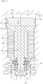
- FIG. 1 is a cross-sectional view of the clamping device 100 according to the first embodiment.
- FIG. 2 is a cross-sectional view of a clamping mechanism 200.
- FIG. 3 is a cross-sectional view of a driving mechanism 400.
- the clamping device 100 of this embodiment is configured as a tool holder clamping device that clamps a tool holder.
- the side (upper side in FIG. 7 ) along center line T of the tool holder 510 that is inserted into shank part insertion space 122 (described below) of the clamping device 100 is referred to as the "rear end side”
- the side (lower side in FIG. 7 ) opposite to the side that is inserted into the shank part insertion space 122 is referred to as the "front end side”.
- the tool holder 510 shown in FIG. 7 holds a tool 550.
- the tool holder 510 has a tool holder rear end surface 510B, a tool holder inner peripheral surface 511 and a tool holder outer peripheral surface 512.
- the tool holder inner peripheral surface 511 has tool holder inner peripheral surface portions 511a to 511f.
- a tool holder interior space 510a having an opening at one end (the rear end) is defined by the tool holder inner peripheral surface 511.
- the tool holder outer peripheral surface 512 has tool holder outer peripheral surface portions 512a to 512c.
- a shank part 520 is provided at a rear end side of the tool holder 510 that is inserted into the shank part insertion space 122 of the clamping device 100.
- the shank part 520 is defined by the tool holder rear end surface 510B, a shank part inner peripheral surface that includes the tool holder inner peripheral surface portions 511b to 511f, and a shank part outer peripheral surface that includes the tool holder outer peripheral surface portion 512c.
- the shank part inner peripheral surface and the shank part outer peripheral surface have a circular cross-section.
- a shank part interior space 520a having an opening at one end (the rear end) is defined by the shank part inner peripheral surface.
- the shank part inner peripheral surface portion (tool holder inner peripheral surface portion) 511e that forms the shank part inner peripheral surface defines a recess 523 that can be engaged with projections 313A (described below) of each of the collet members 310 that forms the collet 300.
- the recess 523 is preferably formed as a groove extending in a circumferential direction.
- the clamping device 100 of this embodiment comprises a body 110, a clamping mechanism 200 and a driving mechanism 400.
- the body 110 has body interior spaces 120 and 130 each having an opening at one end.
- the body interior spaces 120 and 130 are formed such that the extending direction of the body interior space 120 (a center line H1) is orthogonal to the extending direction of the body interior space 130 (a center line H2).
- the extending directions of the body interior spaces 120, 130 can be appropriately selected.
- the body 110 has a communication passage 140 that connects a closed space 121 (described below) formed on the side opposite to the opening of the body interior space 120 and a closed space 131 (described below) formed on the side opposite to the opening of the body interior space 130.
- the body interior space 120 corresponds to a "first body interior space” of the present invention
- the body interior space 130 corresponds to a “second body interior space” of the present invention
- the closed space 121 corresponds to a "first chamber” of the present invention
- the closed space 131 corresponds to a "second chamber” of the present invention
- the communication passage 140 corresponds to a "communication passage” of the present invention.
- a body inner peripheral surface that defines the body interior space 120 has body inner peripheral surface portions 120a to 120l.
- a projection that protrudes toward the center line H1 (radially inward) is defined by the body inner peripheral surface portions 120b to 120d.
- Each of the collet members 310 (described below), which constitute the collet 300, is disposed on the radially outer side of a shaft member 230 (described below) to extend across the projection along the extending direction of the center line H1.
- Each of the collet members 310 is restricted from moving to the side opposite to the closed space 121 along the axial direction when abutting the body inner peripheral surface portion 120d that defines the projection.
- the body inner peripheral surface portion 120d corresponds to a "movement restricting part at a prescribed position of the body that restricts the collet (each of the collet members) from moving to the side opposite to the first chamber along the extending direction of the first body interior space" of the present invention.
- the body inner peripheral surface portion 120h is formed as a step surface that extends in a direction crossing the extending direction of the center line H1 and connects the body inner peripheral surface portions 120g and 120i.
- the body inner peripheral surface portion 120j is formed as a step surface that extends in a direction crossing the extending direction of the center line H1 and connects the body inner peripheral surface portions 120i and 120k.
- the body inner peripheral surface portion 120j serves as a movement restricting part that restricts a movable member 210 from moving to the side opposite to the closed space 121 along the center line H1.
- the body inner peripheral surface portion 120l forms the bottom surface of the body interior space 120.
- the shank part insertion space 122 into which the shank part 520 of the tool holder 510 is inserted is defined on the opening side of the body interior space 120 by the body inner peripheral surface portions 120a and 120b.
- a body inner peripheral surface that defines the body interior space 130 has body inner peripheral surface portions 130a to 130i.
- the body inner peripheral surface portion 130f is formed as a step surface that extends in a direction crossing the extending direction of the center line H2 and connects the body inner peripheral surface portions 130e and 130g.
- the body inner peripheral surface portion 130g serves as a movement restricting part that restricts a movable member 430 (described below) from moving in the direction toward the closed space 131 along the center line H2.
- the body inner peripheral surface portion 130a forms the bottom surface of the body interior space 130.
- the clamping mechanism 200 is disposed in the body interior space 120.
- the clamping mechanism 200 is arranged such that center line P of the clamping mechanism 200 coincides (including “generally coincides") with the center line H1 of the body interior space 120.
- the opening side (lower side in FIGS. 1 and 2 ) is referred to as the "front end side” and the side opposite to the opening (upper side in FIGS. 1 and 2 ) is referred to as the "rear end side", along the extending direction of the body interior space 120 (the center line H1) and the extending direction of the clamping mechanism 200 (the center line P).
- the clamping mechanism 200 includes a movable member 210, a disc spring 260, an annular spring 270, a spring 280 and the collet 300.
- the movable member 210 is movable along the extending direction of the body interior space 120 (hereinafter referred to as "the extending direction of the center line H1").
- the movable member 210 includes a piston 220, a shaft member 230, an actuation member 240 and a pressing member 250.
- the movable member 210 is constituted by connecting the piston 220, the shaft member 230, the actuation member 240 and the pressing member 250, which are separately formed from each other, using bolts, etc.
- the movable member 210 can be formed as a single member.
- the movable member 210 corresponds to a "first movable member" of the present invention.
- the piston 220 has a piston front end surface 220A, a piston rear end surface 212B and a piston outer peripheral surface 222.
- the piston outer peripheral surface 222 has a circular shaped cross-section.
- An O-ring 223 is disposed between the piston outer peripheral surface 222 and the body inner peripheral surface portion 120k.
- the closed space 121 is defined by the body inner peripheral surface portions 120k, 120l and the piston 220 (the piston rear end surface 220B).
- the piston 220 defines the closed space 121.
- the piston 220 corresponds to a "first piston of the first movable member" of the present invention.
- the shaft member 230 extends along the extending direction of the center line H1, on the front end side (the side opposite to the closed space 121) of the piston 220.
- the shaft member 230 has a circular shaped cross-section.
- the shaft member 230 has a shaft member front end surface 230A, a shaft member rear end surface 230B and a shaft member outer peripheral surface 232.
- the shaft member outer peripheral surface 232 has shaft member outer peripheral surface portions 232a to 232d.
- a projection 233, which protrudes radially outward, on the front end side of the shaft member 230 is defined by the shaft member front end surface 230A and the shaft member outer peripheral surface portions 232a to 232c.
- the shaft member outer peripheral surface portion 232b is formed as a tapered surface inclined such that the distance from the center line H1 increases going from the rear end side toward the front end side.
- the shaft member 230 corresponds to a "first shaft member of the first movable member", and the projection 233 corresponds to a "projection of the first shaft member” of the present invention.
- the actuation member 240 is provided on the radially outer side of the shaft member 230 on the front end side of the piston 220 and extends along the center line H1.
- the actuation member 240 has a tubular shape and has an actuation member front end surface 240A, an actuation member rear end surface 240B, an actuation member inner peripheral surface 241 and an actuation member outer peripheral surface 242.
- the actuation member inner peripheral surface 241 and the actuation member outer peripheral surface 242 have a circular cross-section.
- the actuation member front end surface 240A has actuation member front end surface portions 240A1 to 240A3.
- the actuation member front end surface portion 240A2 is formed as a tapered surface inclined such that the distance from the center line H1 (P) increases going from the front end side toward the rear end side.
- the actuation member front end surface portion 240A2 is abuttable on projections 313B (specifically, collet member inner peripheral surface portions 311e) (described below) of the collet members 310 that constitute the collet 300.
- the actuation member inner peripheral surface 241 has actuation member inner peripheral surface portions 241a to 241e.
- a space into which one end of the spring 280 (described below) is insertable is defined by the actuation member inner peripheral surface portions 241c and 241d.
- the actuation member outer peripheral surface 242 has actuation member outer peripheral surface portions 242a to 242e.
- the actuation member outer peripheral surface portion 242b is formed as a step surface that extends in a direction crossing the extending direction of the center line H1 and connects the actuation member outer peripheral surface portions 242a and 242c.
- the actuation member outer peripheral surface portion 242d is formed as a step surface that extends in a direction crossing the extending direction of the center line H1 and connects the actuation member outer peripheral surface portions 242c and 242e.
- the actuation member 240 corresponds to an "actuation member of the first movable member", and the actuation member front end surface portion 240A2 corresponds to an "abutment part of the first movable member that is abuttable on a second projection of each of the collet members" of the present invention.
- the pressing member 250 is provided on the radially outer side of the actuation member 240 on the front end side of the piston 220.
- the pressing member 250 has a tubular shape and has a pressing member front end surface 250A, a pressing member rear end surface 250B, a pressing member inner peripheral surface 251 and a pressing member outer peripheral surface 252.
- the pressing member outer peripheral surface 252 has pressing member outer peripheral surface portions 252a to 252c.
- the pressing member outer peripheral surface portion 252b is formed as a step surface that extends in a direction crossing the extending direction of the center line H1 and connects the pressing member outer peripheral surface portions 252a and 252c.
- the movable member 210 is restricted from moving to the front end side along the center line H1 by the pressing member outer peripheral surface portion 252b abutting on the body inner peripheral surface portion 120j.
- a movement restricting mechanism that restricts movement of the movable member 210 toward the front end side along the center line H1 is constituted by the pressing member outer peripheral surface portion 252b and the body inner peripheral surface portion 120j.
- the pressing member 250 corresponds to a "pressing member of the first movable member" of the present invention.
- the disc spring 260 is disposed in a compressed state between the body inner peripheral surface portion 120h and the pressing member front end surface 250A.
- the disc spring 260 generates an elastic force that moves the movable member 210 along the center line H1 relative to the body 110 toward the rear end side.
- the disc spring 260 corresponds to a "first elastic member that generates an elastic force that moves the first movable member toward a first chamber relative to the body" of the present invention.
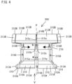
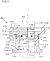
- collet 300 One embodiment of the collet 300 will now be described with reference to FIGS. 4 to 6 .
- FIG. 4 is a side view of the collet 300
- FIG. 5 is a view as seen from the direction of arrow V in FIG. 4
- FIG. 6 is a cross-sectional view taken along line VI-VI in FIG. 5 .
- the collet 300 has a plurality of collet members 310.
- the collet members 310 are disposed on the radially outer side of the shaft member 230, along the circumferential direction on the front end side of the actuation member 240.
- the collet member 310 extends along the circumferential direction and the center line P (H1) on the radially outer side of the shaft member 230, and has a collet member front end surface 310A, a collet member rear end surface 310B, a collet member inner peripheral surface 311 formed on the inner peripheral side, a collet member outer peripheral surface 312 formed on the outer peripheral side, and collet member side surfaces 315 formed on one side and the other side along the circumferential direction. As shown in FIG. 5 , the collet member 310 extends in a circular arc shape along the shaft member outer peripheral surface 231 when viewed from a direction perpendicular to the center line P.
- the collet member inner peripheral surface 311 has collet member inner peripheral surface portions 311a to 311e.
- the collet member inner peripheral surface portion 31 1e is formed as a tapered surface inclined such that the distance from the center line P increases going from the front end side toward the rear end side.
- the collet member inner peripheral surface portion 311a extends at an inclination angle ⁇ to the extending direction of the collet member inner peripheral surface portion 311b when viewed in cross-section taken along the center line P (H1) (see FIG. 6 ).
- the inclination angle ⁇ is set such that the distance between an extension line of the collet member inner peripheral surface portion 311b and the collet member inner peripheral surface portion 311a increases going from the rear end side toward the front end side.
- the other end of the spring 280 abuts the collet member inner peripheral surface portion 311c.
- the collet member outer peripheral surface 312 has collet member outer peripheral surface portions 312a to 312h.
- the collet member outer peripheral surface portion 312g is formed as a tapered surface inclined such that the distance from the center line P (H1) decreases going from the rear end side toward the front end side.
- a projection 313A which protrudes radially outward at a front end side of the collet member 310, is defined by the collet member front end surface 310A and the collet member outer peripheral surface portion 312a.
- the projections 313A are configured to be engageable with the recess 523 of the tool holder 510.
- a projection 313B which protrudes radially outward at a rear end side of the collet member 310, is defined by the collet member rear end surface 310B, the collet member outer peripheral surface portions 312g, 312h, and the collet member inner peripheral surface portions 311b to 311e.
- the projections 313B are configured to be abuttable on the abutment part of the actuation member 240.
- the collet member inner peripheral surface portion 311e that forms the projection 313B is configured to be abuttable on the actuation member front end surface portion 240A2 of the actuation member 240.
- the inclination angle ⁇ of the extending direction of the collet member inner peripheral surface portion 311b to the extending direction of the collet member inner peripheral surface portion 311a is set such that the projection 313A is engageable with the recess 523 of the tool holder 510, which is inserted into the shank part insertion space 122, in the state in which the collet member inner peripheral surface portion 311b has been moved close to (including in abutment with) the shaft member outer peripheral surface 232 (the shaft member outer peripheral surface portion 232d) of the shaft member 230.
- the inclination angle ⁇ is set such that the projections 313A are not engageable with the recess 523 of the tool holder 510 (engagement between the projections 313A and recess 523 is released), which is inserted into the shank part insertion space 122, in the state in which the collet member inner peripheral surface portion 311a has moved close to (including in abutment with) the shaft member outer peripheral surface 232 (the shaft member outer peripheral surface portion 232d) of the shaft member 230.
- the collet member inner peripheral surface portion 311b corresponds to a "first collet member inner peripheral surface portion” of the present invention
- the collet member inner peripheral surface portion 311a corresponds to a "second collet member inner peripheral surface portion” of the present invention
- the projection 313A corresponds to a "first projection that protrudes radially outward from an end part on the front end side (opposite to the first chamber) of the collet member” of the present invention
- the projection 313B corresponds to a "second projection that protrudes radially outward from an end part on the rear end side (the first chamber side) of the collet member" of the present invention.
- a clearance 316 is formed extending along the center line P between two collet members 310 adjacent in the circumferential direction in the state in which the collet member inner peripheral surface portion 311b of each of the collet members 310 is in abutment with the shaft member outer peripheral surface portion 232d (the extending direction of the collet member inner peripheral surface portion 311b is parallel to the extending direction of the shaft member 230).
- the clearance 316 includes a clearance 316B and a clearance 316A, which is formed on the front end side of the clearance 316B and has a larger width than the clearance 316B. Specifically, as shown in FIG.
- the collet member side surface 315 of each of the collet members 310 has collet member side surface portions 315a to 315c.
- the collet member side surface portions 315a and 315c extend along the center line P.
- the collet member side surface portion 315b is formed as a step surface that connects the collet member side surface portions 315a and 315c in a stepwise shape.
- the clearance 316B extends along the center line P with a clearance width N.
- the clearance 316A extends along the center line P with a clearance width M that is larger than the clearance width N of the clearance 316B (M>N).
- the clearance 316B corresponds to a "first clearance formed on the rear end side between the collet members" of the present invention
- the clearance 316A corresponds to a "second clearance formed on the front end side between the collet members" of the present invention.
- the collet 300 is set to a clamping mode in which the collet member inner peripheral surface portions 311b have moved close to the shaft member outer peripheral surface portion 232d while the collet member inner peripheral surface portions 311a are spaced apart from the shaft member outer peripheral surface portion 232d.
- the collet 300 is set to an unclamping mode in which the collet member inner peripheral surface portions 311b are spaced apart from the shaft member outer peripheral surface portion 232d while the collet member inner peripheral surface portions 311a have moved close to the shaft member outer peripheral surface portion 232d.
- the collet 300 is required to be configured such that the collet members 310 adjacent to each other in the circumferential direction do not contact each other when the collet 300 is switched from the clamping mode to the unclamping mode.
- the circumferentially adjacent collet members 310 are disposed at wide intervals.
- the clearance width between the circumferential collet members 310 may vary in the state (clamping mode) in which the collet member inner peripheral surface portions 311b have moved close to the shaft member outer peripheral surface portion 232d. If the clearance width between the circumferential collet members 310 varies, then the clamping force of the tool holder 510 by each of the collet members 310 varies and thus the retaining characteristics of the tool holder 510 may be deteriorated.
- clearances having different clearance widths are formed between the collet members 310 adjacent to each other in the circumferential direction. Further, the clearance width M of the clearances 316A formed on the front end side is larger than the clearance width N of the clearances 316B formed on the rear end side.
- the circumferentially adjacent collet members 310 can be prevented from contacting each other when setting to the unclamping mode. Further, by narrowing the clearance width N of the clearances 316B formed on the rear end side, variation in the clearance width between the collet members 310 can be prevented when the clamping mode is set. Thus, the clamping force of the tool holder 510 by each of the collet members 310 can be generally same and the tool holder 510 can be stably retained.
- the annular spring 270 generates an elastic force that moves each of the collet members 310, which are disposed around the circumferential direction, radially inward.
- a C-shaped annular spring is used as the annular spring 270.
- An O-ring may also be used as the annular spring 270.
- a groove 312A is formed by the collet member outer peripheral surface portions 312d to 312f.
- the groove 312A is formed on the front end side of the projections 313B and at a position of the collet member outer peripheral surface 312 that corresponds to the collet member inner peripheral surface portion 311b, and extends in the circumferential direction.
- the annular spring 270 is inserted in an extended state in the grooves 312A of each of the collet members 310 disposed around the circumferential direction.
- the elastic force of the annular spring 270 acts as a force that moves the collet member inner peripheral surface portions 311b of the collet members 310 toward the shaft member outer peripheral surface portion 232d.
- the annular spring 270 corresponds to a "second elastic member" of the present invention.
- the spring 280 is disposed in a compressed state between each of the collet members 310 and the actuation member 240 (the movable member 210).
- the elastic force of the spring 280 acts as a force that moves each of the collet members 310 and the actuation member 240 (the movable member 210) away from each other.
- Each of the collet members 310 are restricted by the body inner peripheral surface portions 120d from moving along the center line H1 relative to the body 110 toward the front end side (opposite to the closed space 121). Therefore, the elastic force of the spring 280 acts as a force that moves each of the collet members 310 relative to the actuation member 240 (the movable member 210) toward the rear end side.
- each of the collet members 310 is held in abutment on the body inner peripheral surface portion 120d regardless of movement of the movable member 210.
- the spring 280 corresponds to a "third elastic member" of the present invention.
- the driving mechanism 400 is disposed in the body interior space 130.
- the driving mechanism 400 is disposed such that center line Q of the driving mechanism 400 coincides (including “generally coincides") with the center line H2 of the body interior space 130.
- the opening side (right side in FIGS. 1 and 3 ) is referred to as the "rear end side” and the opposite side to the opening (left side in FIGS. 1 and 3 ) is referred to as the "front end side", along the extending direction of the body interior space 130 (the center line H2) and the extending direction of the driving mechanism 400 (the center line Q).
- the driving mechanism 400 is constituted by a rotary member 410 and a movable member 430 that is disposed on the front end side (the closed space 131 side) of the rotary member 410.
- the rotary member 410 is disposed in a body interior space portion defined by the body inner peripheral surface portions 130fto 130i.
- the rotary member 410 has a tubular shape and has a rotary member front end surface 410A, a rotary member inner peripheral surface 411 that defines a rotary member interior space 410a having an opening at the front end side, and a rotary member outer peripheral surface 412.
- the rotary member inner peripheral surface 411 and the rotary member outer peripheral surface 412 have a circular shaped cross-section.
- the rotary member inner peripheral surface 411 has rotary member inner peripheral surface portions 411a to 411d.
- the rotary member inner peripheral surface portion 411b is formed as a step surface that extends in a direction crossing the extending direction of the center line H2 and connects the rotary member inner peripheral surface portions 411a and 411c.
- the rotary member inner peripheral surface portion 41 1d forms a bottom surface of the rotary member interior space 410a.
- a female thread is formed in the rotary member inner peripheral surface portion 411c.
- Bearing members 420 are disposed between the rotary member outer peripheral surface 412 and the body inner peripheral surface portion 130g. Thus, the rotary member 410 is rotatable around the center line H2 relative to the body 110.
- the rotary member 410 is driven by a motor.
- the movable member 430 includes a shaft member 440 and a piston 450, which is disposed on the front end side (the closed space 131 side) of the shaft member 440.
- the movable member 430 is constituted by connecting the shaft member 440 and the piston 450, which are separately formed from each other, using bolts, etc.
- the movable member 430 can be formed as a single member.
- the movable member 430 corresponds to a "second movable member" of the present invention.
- the shaft member 440 has a shaft member front end surface 440A, a shaft member rear end surface 440B and a shaft member outer peripheral surface 442.
- the shaft member outer peripheral surface 442 has a circular shaped cross-section.
- the shaft member outer peripheral surface 442 has shaft member outer peripheral surface portions 442a to 442f.
- a male thread which is threadably engaged with the female thread formed in the rotary member inner peripheral surface portion 411c, is formed on the shaft member outer peripheral surface portion 442f. Further, rotation of the shaft member 440 is restricted by a rotation preventing member 460. Accordingly, the shaft member 440 moves along the center line H2 when the rotary member 410 rotates. Thus, the shaft member 440 acts as a motion converting part that converts rotational motion of the rotary member 410 into linear motion along the center line H2.
- the shaft member 440 corresponds to a "second shaft member of the second movable member" of the present invention.
- the piston 450 has a piston front end surface 450A, a piston rear end surface 450B and a piston outer peripheral surface 452.
- the piston outer peripheral surface 452 has a circular shaped cross-section.
- An O-ring 453 is disposed between the piston outer peripheral surface 452 and the body inner peripheral surface portion 130b.
- the closed space 131 is defined by the body inner peripheral surface portions 130a, 130b and the piston 450 (the piston front end surface 450A).
- the piston 450 defines the closed space 131.
- a power transmitting medium is filled in the closed spaces 121, 131 and the communication passage 140.
- oil is used as the power transmitting medium.
- the piston 450 corresponds to a "second piston of the second movable member" of the present invention.
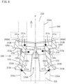
- FIGS. 1 and 8 The state, in which the collet 300 is set to the clamping mode in the state in which the shank part 520 of the tool holder 510 is not inserted in the shank part insertion space 122, is shown in FIGS. 1 and 8 .
- the rotary member 410 of the driving mechanism 400 is rotated in one direction, for example, in a counterclockwise direction.
- the movable member 430 moves in the direction opposite to the closed space 131 (in the direction that increases the volume of the closed space 131) along the center line H2.
- the movable member 210 (the piston 220, the shaft member 230, the actuation member 240, the pressing member 250) of the clamping mechanism 200 will move along the center line H1 in the direction toward the closed space 121 (in the direction that reduces the volume of the closed space 121) due to the elastic force of the disc spring 260.
- each of the collet members 310 that forms the collet 300 is held in abutment with the body inner peripheral surface portion 120d by the elastic force of the spring 280. Then, by moving the movable member 210 in the direction toward the closed space 121, abutment between the actuation member 240 and the projection 313B of each of the collet members 310 (specifically, abutment between the actuation member front end surface portion 240A2 and the collet member inner peripheral surface portions 311e) is released.
- the collet member inner peripheral surface portion 311b of each of the collet members 310 moves toward the shaft member outer peripheral surface 232 (the shaft member outer peripheral surface portion 232d) of the shaft member 230, and the collet member inner peripheral surface portions 331a and the projections 313A move radially outward (in a direction away from the shaft member 230).
- the projection 233 (specifically, the shaft member outer peripheral surface portion 232b that forms the projection 233) of the shaft member 230 abuts a portion of the collet member inner peripheral surface portion 311a of each of the collet members 310. Due to the projection 233 of the shaft member 230 abutting on the collet member inner peripheral surface portion 311a of each of the collet members 310, a force that moves the projection 233 radially outward is applied. This force can be added to the clamping force by the elastic force of the annular spring 270. Thus, the clamping force is increased.
- the collet 300 In order to insert the shank part 520 of the tool holder 510 into the shank part insertion space 122, the collet 300 is required to be set to the unclamping mode.
- the rotary member 410 of the driving mechanism 400 is rotated in the other direction, for example, in the clockwise direction.
- the movable member 430 moves in the direction toward the closed space 131 (in the direction that reduces the volume of the closed space 131) along the center line H2.
- the pressure in the closed space 121 of the clamping mechanism 200 increases, and the movable member 210 moves in the direction opposite to the closed space 121 (in the direction that increases the volume of the closed space 121) along the center line H1 against the elastic force of the disc spring 260.
- the spring 280 is compressed by the movable member 210 moving in the direction opposite to the closed space 121.
- Each of the collet members 310 that forms the collet 300 is held in abutment on the body inner peripheral surface portion 120d by the elastic force of the spring 280.
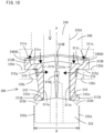
- the actuation member 240 abuts on the projection 313B of each of the collet members 310 (specifically, the actuation member front end surface portion 240A2 abuts on the collet member inner peripheral surface portions 311e). Due to the abutment of the actuation member 240 on the projections 313B, a force that moves the projections 313B radially outward is applied from the actuation member 240 (the actuation member front end surface portion 240A2) to the projection 313B (the collet member inner peripheral surface portion 311e) of each of the collet members 310.
- each of the collet members 310 moves radially outward (in a direction away from the shaft member 230) against the elastic force of the annular spring 270.
- the collet member inner peripheral surface portions 331a and the projections 313A move in a direction toward the shaft member outer peripheral surface 232 (the shaft member outer peripheral surface portion 232d) of the shaft member 230. (see FIGS. 9 and 10 )
- the shank part 520 of the tool holder 510 will be inserted into the shank part insertion space 122.
- the projection 313A of each of the collet members 310 will be inserted into the shank part interior space 520a of the tool holder 510 (see FIG. 11 ).
- the projection 313A of each of the collet members 310 is disposed at a position that faces the recess 523 formed in the shank part inner peripheral surface of the tool holder 510.
- the maximum outer diameter H (see FIG. 10 ) of the projection 313A of each of the collet members 310 is set to be smaller than the inner diameter D (see FIG. 7 ) of the shank part interior space 520a (H ⁇ D).
- the collet 300 will be set to the clamping mode in the state in which the shank part 520 of the tool holder 510 is inserted into the shank part insertion space 122.
- the rotary member 410 of the driving mechanism 400 is rotated in one direction, so that the movable member 430 is moved along the center line H2 in the direction opposite to the closed space 131.
- the movable member 210 of the clamping mechanism 200 moves in the direction toward the closed space 131 along the center line H1 due to the elastic force of the disc spring 260.
- the clamping device 100 of the first embodiment is configured such that the extending direction of the body interior space 120 (the center line H1) in which the clamping mechanism 200 is disposed is orthogonal to the extending direction of the body interior space 130 (the center line H2) in which the driving mechanism 400 is disposed, the extending direction of the body interior space 120 and the extending direction of the body interior space 130 can be appropriately set.
- FIG. 14 A clamping device of a second embodiment is shown in FIG. 14 .
- the clamping device 100 of the second embodiment has the same configuration as the clamping device 100 of the first embodiment except that the extending direction of the body interior space 120 (the center line H1) is parallel to the extending direction of the body interior space 130 (H2) and the shape of the communication passage 140 is different.
- the present invention because closed spaces, which are filled with a power transmitting medium, are used as a power transmitting mechanism between the driving mechanism and the clamping mechanism, it can be easily configured at a low cost.
- the design change is easy because it is only necessary to change the body interior spaces that are formed in the body and the communication passage.
- FIGS. 15 and 16 Another embodiment of a collet 600 is shown in FIGS. 15 and 16 in which the shape of the clearances, which are formed between each two of the collet members that are adjacent in the circumferential direction, has been modified.
- the collet 600 is constituted by a plurality of collet members 610.
- the collet members 610 are disposed along the circumferential direction on the radially outer side of the shaft member outer peripheral surface portion 232d of the shaft member 230 of the movable member 210. Like the collet 300, it is configured such that the elastic force of the annular spring 270 acts as a force that moves a collet member inner peripheral surface portion 611b of each of the collet members 610 toward the shaft member outer peripheral surface portion 232d and moves a collet member inner peripheral surface portion 611a and a projection 613A radially outward (away from the shaft member outer peripheral surface portion 232d).
- a clearance 616 is formed between each two of the collet members 610 that are adjacent in the circumferential direction in the state in which the extending direction of a collet member inner peripheral surface portion 611b of each of the collet members 610 is parallel to the extending direction of the shaft member outer peripheral surface portion 232d.
- the clearance 616 includes a clearance 616A and a clearance 616B.
- the clearance 616A is formed on the front end side of the clearance 616B.
- the clearance 616B extends along the center line P and has clearance width W.
- the clearance 616A extends along the center line P and has a clearance width that gradually increases from a rear end of the clearance width W to a front end of clearance width V (V>W).
- a collet member side surface 615 of each of the collet members 610 has collet member side surface portions 615a and 615b.
- the collet member side surface portion 615b extends in parallel (including "generally parallel") to the center line P, and the collet member side surface portion 615a extends obliquely to the extending direction of the collet member side surface portion 615b (see FIG. 15 ).
- the collet 600 of this embodiment also has the same effects as the collet 300.
- the clearance 616B corresponds to a "first clearance formed on the rear end side between the collet members" of the present invention
- the clearance 616A corresponds to a "second clearance formed on the front end side between the collet members" of the present invention.
- clamping devices are described that are configured to clamp a tool holder that has a shank part and holds a tool
- the present invention can be configured as a clamping device that clamps a variety of members to be clamped such as tools having a shank part.
- a tool holder that has a shank part and holds a tool, and a tool having a shank part are included in a "member to be clamped”.
- the shapes of the body interior space (the first body interior space) in which the clamping mechanism is disposed and the body interior space (the second body interior space) in which the driving mechanism is disposed are not limited to those of the above-described embodiments.
- the shapes and structures of the movable member are not limited to those of the above-described embodiments.
- the clamping mechanism has been constituted by the movable member (the piston, the shaft member, the actuation member, the pressing member), the disc spring, the annular spring, the spring and the collet, the members that constitute the clamping mechanism are not limited to them.
- the movable member (the first movable member) of the clamping mechanism has been constituted by the piston, the shaft member, the actuation member and the pressing member
- the configuration of the movable member (the first movable member) is not limited to this.
- the movable member (the first movable member) can be configured as a single member or by connecting a plurality of members.
- the shapes and configurations of the rotary member, the movable member (the shaft member and the piston), etc. that constitute the driving mechanism are not limited to those of the above-described embodiments.
- the driving mechanism has been constituted by the rotary member and the movable member (the shaft member and the piston), the members that constitute the driving mechanism are not limited to them.
- the movable member (the second movable member) of the driving mechanism has been constituted by the piston and the shaft member
- the configuration of the movable member (the second movable member) is not limited to this.
- the movable member (the second movable member) can be configured as a single member or by connecting a plurality of members.
- the projections (the first and second projections) of the collet member, the projection of the shaft member, the disc spring, the annular spring and the spring may be appropriately selected as necessary.
Landscapes
- Engineering & Computer Science (AREA)
- General Engineering & Computer Science (AREA)
- Mechanical Engineering (AREA)
- Physics & Mathematics (AREA)
- Fluid Mechanics (AREA)
- Gripping On Spindles (AREA)
- Cutting Tools, Boring Holders, And Turrets (AREA)
Abstract
Description
- The present invention relates to a clamping device that clamps a member to be clamped.
- In machine tools that machine a workpiece using a tool, a clamping device is used to clamp a member to be clamped such as the tool or a tool holder that holds the tool. For example, a clamping device disclosed in
Patent Document 1 is used. InPatent Document 1, a clamping device that clamps a member to be clamped or unclamps the member by utilizing rotation of a motor is disclosed. Specifically, the clamping device transmits the rotational power of the motor to the clamping mechanism via a speed reducing mechanism and a motion converting mechanism that converts rotational motion into linear motion. - Patent Document 1:
Japanese Unexamined Patent Application Publication No. 2016-144853 - Because the clamping device disclosed in
Patent Document 1 uses a speed reducing mechanism and a motion converting mechanism that are constituted by using gears, the configuration is complicated and expensive. - The present invention was invented considering these points and it is an object of the present invention to provide a clamping device that can be easily configured at a low cost.
- A member to be clamped by using a clamping device of the present invention has a shank part and the shank part is formed with a recess.
- The clamping device of the present invention has a body, a clamping mechanism and a driving mechanism that drives the clamping mechanism.
- The body has a first body interior space, a second body interior space and a communication passage. The body can be formed by connecting a plurality of members with bolts, etc., or it can be formed as a single member. The extending direction of the first body interior space and the extending direction of the second body interior space can be appropriately set. For example, they can be set to be crossing (including orthogonal) or the same (parallel).
- The clamping mechanism has a first movable member, a first chamber, a first elastic member and a collet. The first movable member is movable along the extending direction of the first body interior space. The volume of the first chamber changes by movement of the first movable member. The first elastic member generates an elastic force that moves the first movable member relative to the body in a direction that reduces the volume of the first chamber. The collet has a first projection that is engageable with the recess of the member to be clamped. Collets of various configurations can be used as the collet.
- The collet is settable to a clamping mode in which the first projection is engaged with the recess, or to an unclamping mode in which the engagement between the first projection and the recess is released. The collet is set to the clamping mode by moving the first movable member in the direction that reduces the volume of the first chamber. Furthermore, the collet is set to the unclamping mode by moving the first movable member is moved in a direction that increases the volume of the first chamber.
- The driving mechanism has a second movable member and a second chamber. The second movable member is movable along an extending direction of the second body interior space. The volume of the second chamber changes by movement of the second movable member.
- The communication passage is formed to connect the first chamber with the second chamber. A power transmitting medium is filed in the first chamber, the second chamber and the communication passage. Oil is preferably used as the power transmitting medium.
- The cross-sectional area of the first chamber is set to be larger than the cross-sectional area of the second chamber. Thus the pressing force that causes the first movable member to move in the direction opposite to the first chamber can be increased.
- In the present invention, when the second movable member moves in a direction that increases the volume of the second chamber, the first movable member moves in the direction that reduces the volume of the first chamber due to the elastic force of the first elastic member and the collet is set to the clamping mode.
- In addition, when the second movable member moves in a direction that reduces the volume of the second chamber, the first movable member moves in the direction that increases the volume of the first chamber against the elastic force of the first elastic member and the collet is set to the unclamping mode.
- Various configurations can be used to set the collet to the clamping mode or the unclamping mode in conjunction with movement of the first movable member.
- In the present invention, a clamping device that can be easily configured at a low cost is provided.
- In a different aspect of this invention, the driving mechanism includes a rotary member. The second movable member is configured to be movable along the extending direction of the second body interior space in conjunction with rotation of the rotary member. Various methods or configurations can be used to move the second movable member in conjunction with rotation of the rotary member.
- Furthermore, it is configured such that, when the rotary member is rotated in one direction, the second movable member moves in the direction that increases the volume of the second chamber, and when the rotary member is rotated in the other direction, the second movable member moves in the direction that reduces the volume of the second chamber.
- In this aspect, for example, when the rotary member is driven by a motor, a pressing force that moves the first movable member in the direction that increases the volume of the first chamber can be obtained with a small motor.
- In this aspect, the driving mechanism can be easily configured.
- In a different aspect of this invention, the shank part of the member to be clamped has a shank part inner peripheral surface that defines a shank part interior space having an opening at one end. The recess is formed in the shank part inner peripheral surface.
- The first movable member includes a first piston and a first shaft member. The first piston defines the first chamber. The first shaft member is provided on a side of the first piston opposite to the first chamber (on the side that increases the volume of the first chamber) and extends along the extending direction of the first body interior space. The first movable member can be formed, for example, by connecting the first piston and the first shaft member that are separately formed from each other with bolts, etc. Or, it can be formed as a single member having the first piston and the first shaft member.
- In addition, the collet includes a plurality of collet members disposed along the circumferential direction on the radially outer side of the first shaft member.
- Each of the collet members extends in the circumferential direction and the axial direction. Each of the collet members has a collet member inner peripheral surface and a collet member outer peripheral surface. The first projection of each of the collet members protrudes radially outward from an end part on a side opposite to the first chamber.
- The collet member inner peripheral surface has, when viewed in cross-section taken along an extending direction of the first shaft member, a first collet member inner peripheral surface portion, and a second collet member inner peripheral surface portion formed on a side of the first collet member inner peripheral surface portion opposite to the first chamber. The second collet member inner peripheral surface portion extends at an inclination angle θ to an extending direction of the first collet member inner peripheral surface portion. The inclination angle θ is set such that the distance between an extension line of the first collet member inner peripheral surface portion and the second collet member inner peripheral surface portion increases from the first chamber side toward the opposite side to the first chamber. For example, the inclination angle θ is set such that the first projection is engageable with the recess of the member to be clamped in the state in which the first collet member inner peripheral surface portion has been moved close to (including in abutment with) an outer peripheral surface of the first shaft member, and such that the engagement between the first projection and the recess of the member to be clamped is released in the state in which the second collet member inner peripheral surface portion has been moved close to (including in abutment with) the outer peripheral surface of the first shaft member.
- In this aspect, it is configured such that, when the first piston moves in the direction (toward the first chamber) that reduces the volume of the first chamber, the first collet member inner peripheral surface portion of each of the collet members moves toward the first shaft member. Specifically, the second collet member inner peripheral surface portions and the first projections are moved away from the first shaft member. The collet is thereby set to the clamping mode.
- In addition it is configured such that, when the first piston moves in the direction (away from the first chamber) that increases the volume of the first chamber, the second collet member inner peripheral surface portion of each of the collet members moves toward the first shaft member. Specifically, the first projections are moved toward the first shaft member and the first collet member inner peripheral surface portions are moved away from the first shaft member. The collet is thereby set to the unclamping mode.
- In this aspect, the collet (the collet members that form the collet) can be easily set to the clamping mode or the unclamping mode.
- In a different aspect of this invention, the clamping mechanism includes a second elastic member. The second elastic member generates elastic force that moves the first collet member inner peripheral surface portion of each of the collet members toward the first shaft member.
- In this aspect, it is configured such that, when the first piston moves in the direction that reduces the volume of the first chamber, the first collet member inner peripheral surface portion of each of the collet members moves toward the first shaft member due to the elastic force of the second elastic member. The collet is thereby set to the clamping mode.
- In addition, it is configured such that, when the first piston moves in the direction that increases the volume of the first chamber, the second collet member inner peripheral surface portion of each of the collet members moves toward the first shaft member against the elastic force of the second elastic member. The collet is thereby set to the unclamping mode.
- In this aspect, the collet can be easily set to the clamping mode or the unclamping mode.
- In a different aspect of this disclosure, each of the collet members has a second projection protruding radially outward at an end part on the first chamber side. The first shaft member has an abutment part configured to be abuttable on the second projection of each of the collet members.
- In this aspect, it is configured such that, when the first piston moves in the direction that reduces the volume of the first chamber, abutment between the abutment part of the first movable member and the second projection of each of the collet members is released. Furthermore, it is configured such that the first collet member inner peripheral surface portion of each of the collet members moves toward the first shaft member due to the elastic force of the second elastic member. The collet is thereby set to the clamping mode.
- In addition, it is configured such that, when the first piston moves in the direction that increases the volume of the first chamber, the abutment part of the first movable member abuts the second projection of each of the collet members and applies a force that moves the second projection radially outward. Furthermore, it is configured such that the second collet member inner peripheral surface portion of each of the collet members moves toward the first shaft member against the elastic force of the second elastic member. The collet is thereby set to the unclamping mode.
- In this aspect, the collet can be easily set to the clamping mode or the unclamping mode.
- In a different aspect of this invention, the first shaft member has a projection protruding radially outward at the end part on the side opposite to the first chamber.
- In this aspect, it is configured such that, when the first piston moves in the direction that reduces the volume of the first chamber, the projection of the first shaft member abuts on a portion of the second collet member inner peripheral surface portion of each of the collet members and applies a force that moves the second collet member inner peripheral surface portion away from the first shaft member. The collet is thereby set to the clamping mode.
- In addition, it is configured such that, when the first piston moves in the direction that increases the volume of the first chamber, abutment between the projection of the first shaft member and the portion of the second collet member inner peripheral surface portion of each of the collet members is released. In addition, at this time, it is configured such that the second collet member inner peripheral surface portion of each of the collet members moves toward the first shaft member. The collet is thereby set to the unclamping mode.
- In this aspect, the clamping force can be increased, so that engagement between the first projection and the recess of the member to be clamped can be firmly retained.
- In a different aspect of this invention, the body has a movement restricting part at a prescribed position that restricts each of the collet members from moving along the extending direction of the first body interior space in the direction that increases the volume of the first chamber.
- The clamping mechanism has a third elastic member. The third elastic member is configured to generate an elastic force that moves the first movable member and each of the collet members away from each other.
- Each of the collet members is disposed at a prescribed position regardless of movement of the first movable member due to the movement restricting part and the elastic force of the third elastic member.
- In this aspect, the collet can be easily set to the clamping mode or the unclamping mode.
- In a different aspect of this invention, the second movable member includes a second piston and a second shaft member. The second piston defines the first chamber. The second shaft member is provided on a side opposite to the second chamber and extends along the extending direction of the second body interior space. It is configured such that the second shaft member is movable along the extending direction of the second body interior space in conjunction with rotation of the rotary member.
- The second movable member can be formed, for example, by connecting the second piston and the second shaft member that are separately formed from each other with bolts, etc. Or, it can be formed as a single member having the second piston and the second shaft member.
- In this aspect, rotation of the rotary member can be converted into movement along the extending direction of the second body interior space with a simple structure.
- According to this invention, a clamping device that can be easily configured at a low cost can be obtained.
-
-
FIG. 1 is a cross-sectional view of a clamping device according to a first embodiment. -
FIG. 2 is a cross-sectional view of a clamping mechanism that forms the clamping device of the first embodiment. -
FIG. 3 is a cross-sectional view of a driving mechanism that forms the clamping device of the first embodiment. -
FIG. 4 is a side view of an embodiment of a collet used in the clamping mechanism that forms the clamping device of the first embodiment. -
FIG. 5 is a view as seen from the direction of arrow V inFIG. 4 . -
FIG. 6 is a cross-sectional view taken along line VI-VI inFIG. 5 . -
FIG. 7 is a cross-sectional view of an example of a clamped member to be clamped by the clamping device of the first embodiment. -
FIG. 8 is a figure that shows the collet in a state in which a shank part of the member to be clamped is not inserted into a shank part insertion space when the clamping device of the first embodiment is set to a clamping mode (shown inFIG. 1 ). -
FIG. 9 is a figure that shows a state in which the shank part of the member to be clamped is not inserted into the shank part insertion space in a state in which the clamping device of the first embodiment is set to an unclamping mode. -
FIG. 10 is a figure that shows the collet in the state shown inFIG. 9 . -
FIG. 11 is a figure that shows a state in which the shank part of a tool holder is inserted into the shank part insertion space in the state in which the clamping device of the first embodiment is set to the unclamping mode. -
FIG. 12 is a figure that shows a state in which the clamping device of the first embodiment is set to the clamping mode in the state in which the shank part of the tool holder is inserted into the shank part insertion space. -
FIG. 13 is a figure that shows the collet in the state shown inFIG. 12 . -
FIG. 14 is a cross-sectional view of a clamping device according to a second embodiment. -
FIG. 15 is a side view of a different embodiment of a collet. -
FIG. 16 is a figure that shows the collet of a different embodiment in a state being set to the unclamping mode. - The following detailed description is merely intended to teach a person skilled in the art further details for practicing preferred aspects of the present invention. The technical scope of the present invention is not limited by the detailed description, but is determined based on the description of the claims. Combinations of features and steps disclosed within the following detailed description may not be necessary to practice the invention in the broadest sense, and are merely to particularly describe some representative examples of the invention, which detailed description is given with reference to the accompanying drawings.
- Representative embodiments of the present invention are now described with reference to the drawings.
- A
clamping device 100 according to a first embodiment of the present invention is described with reference toFIGS. 1 to 3 .FIG. 1 is a cross-sectional view of theclamping device 100 according to the first embodiment.FIG. 2 is a cross-sectional view of aclamping mechanism 200.FIG. 3 is a cross-sectional view of adriving mechanism 400. - The
clamping device 100 of this embodiment is configured as a tool holder clamping device that clamps a tool holder. - An example of a tool holder that is clamped by the
clamping device 100 of this embodiment will be described with reference toFIG. 7 . - It is noted that, in the following with regard to a
tool holder 510, the side (upper side inFIG. 7 ) along center line T of thetool holder 510 that is inserted into shank part insertion space 122 (described below) of theclamping device 100 is referred to as the "rear end side", and the side (lower side inFIG. 7 ) opposite to the side that is inserted into the shankpart insertion space 122 is referred to as the "front end side". - The
tool holder 510 shown inFIG. 7 holds atool 550. - The
tool holder 510 has a tool holderrear end surface 510B, a tool holder innerperipheral surface 511 and a tool holder outer peripheral surface 512. - The tool holder inner
peripheral surface 511 has tool holder inner peripheral surface portions 511a to 511f. A tool holder interior space 510a having an opening at one end (the rear end) is defined by the tool holder innerperipheral surface 511. The tool holder outer peripheral surface 512 has tool holder outerperipheral surface portions 512a to 512c. - A
shank part 520 is provided at a rear end side of thetool holder 510 that is inserted into the shankpart insertion space 122 of theclamping device 100. Theshank part 520 is defined by the tool holderrear end surface 510B, a shank part inner peripheral surface that includes the tool holder innerperipheral surface portions 511b to 511f, and a shank part outer peripheral surface that includes the tool holder outerperipheral surface portion 512c. The shank part inner peripheral surface and the shank part outer peripheral surface have a circular cross-section. A shank partinterior space 520a having an opening at one end (the rear end) is defined by the shank part inner peripheral surface. The shank part inner peripheral surface portion (tool holder inner peripheral surface portion) 511e that forms the shank part inner peripheral surface defines arecess 523 that can be engaged withprojections 313A (described below) of each of thecollet members 310 that forms thecollet 300. Therecess 523 is preferably formed as a groove extending in a circumferential direction. - The
clamping device 100 of this embodiment comprises abody 110, aclamping mechanism 200 and adriving mechanism 400. - The
body 110 has bodyinterior spaces interior spaces interior spaces - It is noted that the
body 110 has acommunication passage 140 that connects a closed space 121 (described below) formed on the side opposite to the opening of the bodyinterior space 120 and a closed space 131 (described below) formed on the side opposite to the opening of the bodyinterior space 130. - The body
interior space 120 corresponds to a "first body interior space" of the present invention, and the bodyinterior space 130 corresponds to a "second body interior space" of the present invention. Theclosed space 121 corresponds to a "first chamber" of the present invention, and theclosed space 131 corresponds to a "second chamber" of the present invention. Thecommunication passage 140 corresponds to a "communication passage" of the present invention. - As shown in
FIG. 2 , a body inner peripheral surface that defines the bodyinterior space 120 has body innerperipheral surface portions 120a to 120l. - A projection that protrudes toward the center line H1 (radially inward) is defined by the body inner
peripheral surface portions 120b to 120d. Each of the collet members 310 (described below), which constitute thecollet 300, is disposed on the radially outer side of a shaft member 230 (described below) to extend across the projection along the extending direction of the center line H1. Each of thecollet members 310 is restricted from moving to the side opposite to theclosed space 121 along the axial direction when abutting the body innerperipheral surface portion 120d that defines the projection. - The body inner
peripheral surface portion 120d corresponds to a "movement restricting part at a prescribed position of the body that restricts the collet (each of the collet members) from moving to the side opposite to the first chamber along the extending direction of the first body interior space" of the present invention. - The body inner
peripheral surface portion 120h is formed as a step surface that extends in a direction crossing the extending direction of the center line H1 and connects the body innerperipheral surface portions - The body inner
peripheral surface portion 120j is formed as a step surface that extends in a direction crossing the extending direction of the center line H1 and connects the body innerperipheral surface portions peripheral surface portion 120j serves as a movement restricting part that restricts amovable member 210 from moving to the side opposite to theclosed space 121 along the center line H1. - The body inner peripheral surface portion 120l forms the bottom surface of the body
interior space 120. - The shank
part insertion space 122 into which theshank part 520 of thetool holder 510 is inserted is defined on the opening side of the bodyinterior space 120 by the body innerperipheral surface portions - As shown in
FIG. 3 , a body inner peripheral surface that defines the bodyinterior space 130 has body innerperipheral surface portions 130a to 130i. - The body inner
peripheral surface portion 130f is formed as a step surface that extends in a direction crossing the extending direction of the center line H2 and connects the body innerperipheral surface portions 130e and 130g. The body innerperipheral surface portion 130g serves as a movement restricting part that restricts a movable member 430 (described below) from moving in the direction toward theclosed space 131 along the center line H2. - The body inner
peripheral surface portion 130a forms the bottom surface of the bodyinterior space 130. - The
clamping mechanism 200 is disposed in the bodyinterior space 120. In this embodiment, theclamping mechanism 200 is arranged such that center line P of theclamping mechanism 200 coincides (including "generally coincides") with the center line H1 of the bodyinterior space 120. - In the following description of the
clamping mechanism 200, the opening side (lower side inFIGS. 1 and2 ) is referred to as the "front end side" and the side opposite to the opening (upper side inFIGS. 1 and2 ) is referred to as the "rear end side", along the extending direction of the body interior space 120 (the center line H1) and the extending direction of the clamping mechanism 200 (the center line P). - The
clamping mechanism 200 includes amovable member 210, adisc spring 260, anannular spring 270, aspring 280 and thecollet 300. - The
movable member 210 is movable along the extending direction of the body interior space 120 (hereinafter referred to as "the extending direction of the center line H1"). Themovable member 210 includes apiston 220, ashaft member 230, anactuation member 240 and apressing member 250. In this embodiment, themovable member 210 is constituted by connecting thepiston 220, theshaft member 230, theactuation member 240 and thepressing member 250, which are separately formed from each other, using bolts, etc. Themovable member 210 can be formed as a single member. - The
movable member 210 corresponds to a "first movable member" of the present invention. - The
piston 220 has a pistonfront end surface 220A, a piston rear end surface 212B and a piston outerperipheral surface 222. The piston outerperipheral surface 222 has a circular shaped cross-section. - An O-
ring 223 is disposed between the piston outerperipheral surface 222 and the body innerperipheral surface portion 120k. Thus, theclosed space 121 is defined by the body innerperipheral surface portions 120k, 120l and the piston 220 (the pistonrear end surface 220B). Specifically, thepiston 220 defines theclosed space 121. - The
piston 220 corresponds to a "first piston of the first movable member" of the present invention. - The
shaft member 230 extends along the extending direction of the center line H1, on the front end side (the side opposite to the closed space 121) of thepiston 220. In this embodiment, theshaft member 230 has a circular shaped cross-section. - The
shaft member 230 has a shaft memberfront end surface 230A, a shaft member rear end surface 230B and a shaft member outerperipheral surface 232. - The shaft member outer
peripheral surface 232 has shaft member outerperipheral surface portions 232a to 232d. Aprojection 233, which protrudes radially outward, on the front end side of theshaft member 230 is defined by the shaft memberfront end surface 230A and the shaft member outerperipheral surface portions 232a to 232c. In this embodiment, the shaft member outerperipheral surface portion 232b is formed as a tapered surface inclined such that the distance from the center line H1 increases going from the rear end side toward the front end side. - The
shaft member 230 corresponds to a "first shaft member of the first movable member", and theprojection 233 corresponds to a "projection of the first shaft member" of the present invention. - The
actuation member 240 is provided on the radially outer side of theshaft member 230 on the front end side of thepiston 220 and extends along the center line H1. - The
actuation member 240 has a tubular shape and has an actuation member front end surface 240A, an actuation memberrear end surface 240B, an actuation member innerperipheral surface 241 and an actuation member outer peripheral surface 242. The actuation member innerperipheral surface 241 and the actuation member outer peripheral surface 242 have a circular cross-section. - The actuation member front end surface 240A has actuation member front end surface portions 240A1 to 240A3. The actuation member front end surface portion 240A2 is formed as a tapered surface inclined such that the distance from the center line H1 (P) increases going from the front end side toward the rear end side. The actuation member front end surface portion 240A2 is abuttable on
projections 313B (specifically, collet member innerperipheral surface portions 311e) (described below) of thecollet members 310 that constitute thecollet 300. - The actuation member inner
peripheral surface 241 has actuation member inner peripheral surface portions 241a to 241e. A space into which one end of the spring 280 (described below) is insertable is defined by the actuation member innerperipheral surface portions 241c and 241d. - The actuation member outer peripheral surface 242 has actuation member outer
peripheral surface portions 242a to 242e. - The actuation member outer
peripheral surface portion 242b is formed as a step surface that extends in a direction crossing the extending direction of the center line H1 and connects the actuation member outerperipheral surface portions - The actuation member outer
peripheral surface portion 242d is formed as a step surface that extends in a direction crossing the extending direction of the center line H1 and connects the actuation member outerperipheral surface portions - The
actuation member 240 corresponds to an "actuation member of the first movable member", and the actuation member front end surface portion 240A2 corresponds to an "abutment part of the first movable member that is abuttable on a second projection of each of the collet members" of the present invention. - The pressing
member 250 is provided on the radially outer side of theactuation member 240 on the front end side of thepiston 220. - The pressing
member 250 has a tubular shape and has a pressing memberfront end surface 250A, a pressing memberrear end surface 250B, a pressing member innerperipheral surface 251 and a pressing member outer peripheral surface 252. - The pressing member outer peripheral surface 252 has pressing member outer
peripheral surface portions 252a to 252c. The pressing member outerperipheral surface portion 252b is formed as a step surface that extends in a direction crossing the extending direction of the center line H1 and connects the pressing member outerperipheral surface portions - The
movable member 210 is restricted from moving to the front end side along the center line H1 by the pressing member outerperipheral surface portion 252b abutting on the body innerperipheral surface portion 120j. Specifically, a movement restricting mechanism that restricts movement of themovable member 210 toward the front end side along the center line H1 is constituted by the pressing member outerperipheral surface portion 252b and the body innerperipheral surface portion 120j. - The pressing
member 250 corresponds to a "pressing member of the first movable member" of the present invention. - The
disc spring 260 is disposed in a compressed state between the body innerperipheral surface portion 120h and the pressing memberfront end surface 250A. Thus, thedisc spring 260 generates an elastic force that moves themovable member 210 along the center line H1 relative to thebody 110 toward the rear end side. - The
disc spring 260 corresponds to a "first elastic member that generates an elastic force that moves the first movable member toward a first chamber relative to the body" of the present invention. - One embodiment of the
collet 300 will now be described with reference toFIGS. 4 to 6 . -
FIG. 4 is a side view of thecollet 300,FIG. 5 is a view as seen from the direction of arrow V inFIG. 4 , andFIG. 6 is a cross-sectional view taken along line VI-VI inFIG. 5 . - The
collet 300 has a plurality ofcollet members 310. - The
collet members 310 are disposed on the radially outer side of theshaft member 230, along the circumferential direction on the front end side of theactuation member 240. - The
collet member 310 extends along the circumferential direction and the center line P (H1) on the radially outer side of theshaft member 230, and has a collet memberfront end surface 310A, a collet memberrear end surface 310B, a collet member innerperipheral surface 311 formed on the inner peripheral side, a collet member outer peripheral surface 312 formed on the outer peripheral side, and collet member side surfaces 315 formed on one side and the other side along the circumferential direction. As shown inFIG. 5 , thecollet member 310 extends in a circular arc shape along the shaft member outer peripheral surface 231 when viewed from a direction perpendicular to the center line P. - The collet member inner
peripheral surface 311 has collet member innerperipheral surface portions 311a to 311e. The collet member inner peripheral surface portion 31 1e is formed as a tapered surface inclined such that the distance from the center line P increases going from the front end side toward the rear end side. - The collet member inner
peripheral surface portion 311a extends at an inclination angle θ to the extending direction of the collet member innerperipheral surface portion 311b when viewed in cross-section taken along the center line P (H1) (seeFIG. 6 ). The inclination angle θ is set such that the distance between an extension line of the collet member innerperipheral surface portion 311b and the collet member innerperipheral surface portion 311a increases going from the rear end side toward the front end side. - The other end of the
spring 280 abuts the collet member innerperipheral surface portion 311c. - The collet member outer peripheral surface 312 has collet member outer
peripheral surface portions 312a to 312h. The collet member outerperipheral surface portion 312g is formed as a tapered surface inclined such that the distance from the center line P (H1) decreases going from the rear end side toward the front end side. - A
projection 313A, which protrudes radially outward at a front end side of thecollet member 310, is defined by the collet memberfront end surface 310A and the collet member outerperipheral surface portion 312a. Theprojections 313A are configured to be engageable with therecess 523 of thetool holder 510. - A
projection 313B, which protrudes radially outward at a rear end side of thecollet member 310, is defined by the collet memberrear end surface 310B, the collet member outerperipheral surface portions peripheral surface portions 311b to 311e. Theprojections 313B are configured to be abuttable on the abutment part of theactuation member 240. Specifically, the collet member innerperipheral surface portion 311e that forms theprojection 313B is configured to be abuttable on the actuation member front end surface portion 240A2 of theactuation member 240. - The inclination angle θ of the extending direction of the collet member inner
peripheral surface portion 311b to the extending direction of the collet member innerperipheral surface portion 311a is set such that theprojection 313A is engageable with therecess 523 of thetool holder 510, which is inserted into the shankpart insertion space 122, in the state in which the collet member innerperipheral surface portion 311b has been moved close to (including in abutment with) the shaft member outer peripheral surface 232 (the shaft member outerperipheral surface portion 232d) of theshaft member 230. Further, the inclination angle θ is set such that theprojections 313A are not engageable with therecess 523 of the tool holder 510 (engagement between theprojections 313A andrecess 523 is released), which is inserted into the shankpart insertion space 122, in the state in which the collet member innerperipheral surface portion 311a has moved close to (including in abutment with) the shaft member outer peripheral surface 232 (the shaft member outerperipheral surface portion 232d) of theshaft member 230. - The collet member inner
peripheral surface portion 311b corresponds to a "first collet member inner peripheral surface portion" of the present invention, and the collet member innerperipheral surface portion 311a corresponds to a "second collet member inner peripheral surface portion" of the present invention. Theprojection 313A corresponds to a "first projection that protrudes radially outward from an end part on the front end side (opposite to the first chamber) of the collet member" of the present invention, and theprojection 313B corresponds to a "second projection that protrudes radially outward from an end part on the rear end side (the first chamber side) of the collet member" of the present invention. - As shown in
FIGS. 4 to 6 , a clearance 316 is formed extending along the center line P between twocollet members 310 adjacent in the circumferential direction in the state in which the collet member innerperipheral surface portion 311b of each of thecollet members 310 is in abutment with the shaft member outerperipheral surface portion 232d (the extending direction of the collet member innerperipheral surface portion 311b is parallel to the extending direction of the shaft member 230). The clearance 316 includes aclearance 316B and aclearance 316A, which is formed on the front end side of theclearance 316B and has a larger width than theclearance 316B. Specifically, as shown inFIG. 4 , the collet member side surface 315 of each of thecollet members 310 has collet memberside surface portions 315a to 315c. The collet memberside surface portions side surface portion 315b is formed as a step surface that connects the collet memberside surface portions - In this embodiment, the
clearance 316B extends along the center line P with a clearance width N. Theclearance 316A extends along the center line P with a clearance width M that is larger than the clearance width N of theclearance 316B (M>N). - The
clearance 316B corresponds to a "first clearance formed on the rear end side between the collet members" of the present invention, and theclearance 316A corresponds to a "second clearance formed on the front end side between the collet members" of the present invention. - In this embodiment, as described below, the
collet 300 is set to a clamping mode in which the collet member innerperipheral surface portions 311b have moved close to the shaft member outerperipheral surface portion 232d while the collet member innerperipheral surface portions 311a are spaced apart from the shaft member outerperipheral surface portion 232d. In addition, thecollet 300 is set to an unclamping mode in which the collet member innerperipheral surface portions 311b are spaced apart from the shaft member outerperipheral surface portion 232d while the collet member innerperipheral surface portions 311a have moved close to the shaft member outerperipheral surface portion 232d. Here, thecollet 300 is required to be configured such that thecollet members 310 adjacent to each other in the circumferential direction do not contact each other when thecollet 300 is switched from the clamping mode to the unclamping mode. For example, the circumferentiallyadjacent collet members 310 are disposed at wide intervals. - However, if the circumferentially
adjacent collet members 310 are disposed with large gaps, then the clearance width between thecircumferential collet members 310 may vary in the state (clamping mode) in which the collet member innerperipheral surface portions 311b have moved close to the shaft member outerperipheral surface portion 232d. If the clearance width between thecircumferential collet members 310 varies, then the clamping force of thetool holder 510 by each of thecollet members 310 varies and thus the retaining characteristics of thetool holder 510 may be deteriorated. - In this embodiment, clearances having different clearance widths are formed between the
collet members 310 adjacent to each other in the circumferential direction. Further, the clearance width M of theclearances 316A formed on the front end side is larger than the clearance width N of theclearances 316B formed on the rear end side. - By widening the clearance width M of the
clearance 316A formed on the front end side, the circumferentiallyadjacent collet members 310 can be prevented from contacting each other when setting to the unclamping mode. Further, by narrowing the clearance width N of theclearances 316B formed on the rear end side, variation in the clearance width between thecollet members 310 can be prevented when the clamping mode is set. Thus, the clamping force of thetool holder 510 by each of thecollet members 310 can be generally same and thetool holder 510 can be stably retained. - The
annular spring 270 generates an elastic force that moves each of thecollet members 310, which are disposed around the circumferential direction, radially inward. In this embodiment, a C-shaped annular spring is used as theannular spring 270. An O-ring may also be used as theannular spring 270. - In this embodiment, as shown in
FIG. 6 , agroove 312A is formed by the collet member outerperipheral surface portions 312d to 312f. Thegroove 312A is formed on the front end side of theprojections 313B and at a position of the collet member outer peripheral surface 312 that corresponds to the collet member innerperipheral surface portion 311b, and extends in the circumferential direction. - The
annular spring 270 is inserted in an extended state in thegrooves 312A of each of thecollet members 310 disposed around the circumferential direction. Thus, the elastic force of theannular spring 270 acts as a force that moves the collet member innerperipheral surface portions 311b of thecollet members 310 toward the shaft member outerperipheral surface portion 232d. - The
annular spring 270 corresponds to a "second elastic member" of the present invention. - The
spring 280 is disposed in a compressed state between each of thecollet members 310 and the actuation member 240 (the movable member 210). The elastic force of thespring 280 acts as a force that moves each of thecollet members 310 and the actuation member 240 (the movable member 210) away from each other. Each of thecollet members 310 are restricted by the body innerperipheral surface portions 120d from moving along the center line H1 relative to thebody 110 toward the front end side (opposite to the closed space 121). Therefore, the elastic force of thespring 280 acts as a force that moves each of thecollet members 310 relative to the actuation member 240 (the movable member 210) toward the rear end side. Thus, each of thecollet members 310 is held in abutment on the body innerperipheral surface portion 120d regardless of movement of themovable member 210. - The
spring 280 corresponds to a "third elastic member" of the present invention. - The
driving mechanism 400 is disposed in the bodyinterior space 130. In this embodiment, thedriving mechanism 400 is disposed such that center line Q of thedriving mechanism 400 coincides (including "generally coincides") with the center line H2 of the bodyinterior space 130. - In the following description of the
driving mechanism 400, the opening side (right side inFIGS. 1 and3 ) is referred to as the "rear end side" and the opposite side to the opening (left side inFIGS. 1 and3 ) is referred to as the "front end side", along the extending direction of the body interior space 130 (the center line H2) and the extending direction of the driving mechanism 400 (the center line Q). - As shown in
FIG. 3 , thedriving mechanism 400 is constituted by arotary member 410 and amovable member 430 that is disposed on the front end side (theclosed space 131 side) of therotary member 410. - The
rotary member 410 is disposed in a body interior space portion defined by the body inner peripheral surface portions 130fto 130i. Therotary member 410 has a tubular shape and has a rotary memberfront end surface 410A, a rotary member inner peripheral surface 411 that defines a rotary memberinterior space 410a having an opening at the front end side, and a rotary member outerperipheral surface 412. The rotary member inner peripheral surface 411 and the rotary member outerperipheral surface 412 have a circular shaped cross-section. - The rotary member inner peripheral surface 411 has rotary member inner
peripheral surface portions 411a to 411d. The rotary member inner peripheral surface portion 411b is formed as a step surface that extends in a direction crossing the extending direction of the center line H2 and connects the rotary member innerperipheral surface portions interior space 410a. A female thread is formed in the rotary member innerperipheral surface portion 411c. -
Bearing members 420 are disposed between the rotary member outerperipheral surface 412 and the body innerperipheral surface portion 130g. Thus, therotary member 410 is rotatable around the center line H2 relative to thebody 110. - In this embodiment, the
rotary member 410 is driven by a motor. - The
movable member 430 includes ashaft member 440 and apiston 450, which is disposed on the front end side (theclosed space 131 side) of theshaft member 440. In this embodiment, themovable member 430 is constituted by connecting theshaft member 440 and thepiston 450, which are separately formed from each other, using bolts, etc. Themovable member 430 can be formed as a single member. - The
movable member 430 corresponds to a "second movable member" of the present invention. - The
shaft member 440 has a shaft memberfront end surface 440A, a shaft member rear end surface 440B and a shaft member outerperipheral surface 442. The shaft member outerperipheral surface 442 has a circular shaped cross-section. - The shaft member outer
peripheral surface 442 has shaft member outerperipheral surface portions 442a to 442f. - A male thread, which is threadably engaged with the female thread formed in the rotary member inner
peripheral surface portion 411c, is formed on the shaft member outerperipheral surface portion 442f. Further, rotation of theshaft member 440 is restricted by arotation preventing member 460. Accordingly, theshaft member 440 moves along the center line H2 when therotary member 410 rotates. Thus, theshaft member 440 acts as a motion converting part that converts rotational motion of therotary member 410 into linear motion along the center line H2. - The
shaft member 440 corresponds to a "second shaft member of the second movable member" of the present invention. - The
piston 450 has a pistonfront end surface 450A, a pistonrear end surface 450B and a piston outerperipheral surface 452. The piston outerperipheral surface 452 has a circular shaped cross-section. - An O-
ring 453 is disposed between the piston outerperipheral surface 452 and the body innerperipheral surface portion 130b. Thus, theclosed space 131 is defined by the body innerperipheral surface portions front end surface 450A). Specifically, thepiston 450 defines theclosed space 131. - It is noted that a power transmitting medium is filled in the
closed spaces communication passage 140. In this embodiment, oil is used as the power transmitting medium. - The
piston 450 corresponds to a "second piston of the second movable member" of the present invention. - Operation of the
clamping device 100 of the first embodiment will now be described with reference toFIGS. 8 to 13 . - The state, in which the
collet 300 is set to the clamping mode in the state in which theshank part 520 of thetool holder 510 is not inserted in the shankpart insertion space 122, is shown inFIGS. 1 and8 . - In the situation in which the
collet 300 will be set to the clamping mode, therotary member 410 of thedriving mechanism 400 is rotated in one direction, for example, in a counterclockwise direction. When therotary member 410 rotates in the one direction, the movable member 430 (theshaft member 440, the piston 450) moves in the direction opposite to the closed space 131 (in the direction that increases the volume of the closed space 131) along the center line H2. Thus, the movable member 210 (thepiston 220, theshaft member 230, theactuation member 240, the pressing member 250) of theclamping mechanism 200 will move along the center line H1 in the direction toward the closed space 121 (in the direction that reduces the volume of the closed space 121) due to the elastic force of thedisc spring 260. - At this time, each of the
collet members 310 that forms thecollet 300 is held in abutment with the body innerperipheral surface portion 120d by the elastic force of thespring 280. Then, by moving themovable member 210 in the direction toward theclosed space 121, abutment between theactuation member 240 and theprojection 313B of each of the collet members 310 (specifically, abutment between the actuation member front end surface portion 240A2 and the collet member innerperipheral surface portions 311e) is released. Thus, due to the elastic force of theannular spring 270, the collet member innerperipheral surface portion 311b of each of thecollet members 310 moves toward the shaft member outer peripheral surface 232 (the shaft member outerperipheral surface portion 232d) of theshaft member 230, and the collet member inner peripheral surface portions 331a and theprojections 313A move radially outward (in a direction away from the shaft member 230). - Further, by moving the
movable member 210 in the direction toward theclosed space 121, the projection 233 (specifically, the shaft member outerperipheral surface portion 232b that forms the projection 233) of theshaft member 230 abuts a portion of the collet member innerperipheral surface portion 311a of each of thecollet members 310. Due to theprojection 233 of theshaft member 230 abutting on the collet member innerperipheral surface portion 311a of each of thecollet members 310, a force that moves theprojection 233 radially outward is applied. This force can be added to the clamping force by the elastic force of theannular spring 270. Thus, the clamping force is increased. - Next, an operation that inserts the
shank part 520 of thetool holder 510 into the shankpart insertion space 122 will be described with reference toFIGS. 9 to 11 . - In order to insert the
shank part 520 of thetool holder 510 into the shankpart insertion space 122, thecollet 300 is required to be set to the unclamping mode. - In the situation in which the
collet 300 will be set to the unclamping mode, therotary member 410 of thedriving mechanism 400 is rotated in the other direction, for example, in the clockwise direction. When therotary member 410 rotates in the other direction, themovable member 430 moves in the direction toward the closed space 131 (in the direction that reduces the volume of the closed space 131) along the center line H2. Thus, the pressure in theclosed space 121 of theclamping mechanism 200 increases, and themovable member 210 moves in the direction opposite to the closed space 121 (in the direction that increases the volume of the closed space 121) along the center line H1 against the elastic force of thedisc spring 260. - By moving the
movable member 210 in the direction opposite to theclosed space 121, abutment between theprojection 233 of theshaft member 230 and the collet member innerperipheral surface portion 311a of each of thecollet members 310 is released. - At this time, the
spring 280 is compressed by themovable member 210 moving in the direction opposite to theclosed space 121. Each of thecollet members 310 that forms thecollet 300 is held in abutment on the body innerperipheral surface portion 120d by the elastic force of thespring 280. - Further, due to the movement of the
movable member 210 in the direction opposite to theclosed space 121, theactuation member 240 abuts on theprojection 313B of each of the collet members 310 (specifically, the actuation member front end surface portion 240A2 abuts on the collet member innerperipheral surface portions 311e). Due to the abutment of theactuation member 240 on theprojections 313B, a force that moves theprojections 313B radially outward is applied from the actuation member 240 (the actuation member front end surface portion 240A2) to theprojection 313B (the collet member innerperipheral surface portion 311e) of each of thecollet members 310. Thus, the collet member innerperipheral surface portion 311b of each of thecollet members 310 moves radially outward (in a direction away from the shaft member 230) against the elastic force of theannular spring 270. At the same time, the collet member inner peripheral surface portions 331a and theprojections 313A move in a direction toward the shaft member outer peripheral surface 232 (the shaft member outerperipheral surface portion 232d) of theshaft member 230. (seeFIGS. 9 and10 ) - Then, in the state in which the
collet 300 is set to the unclamping mode, theshank part 520 of thetool holder 510 will be inserted into the shankpart insertion space 122. At this time, theprojection 313A of each of thecollet members 310 will be inserted into the shank partinterior space 520a of the tool holder 510 (seeFIG. 11 ). Theprojection 313A of each of thecollet members 310 is disposed at a position that faces therecess 523 formed in the shank part inner peripheral surface of thetool holder 510. - It is noted that, in the state in which the
collet 300 has been set to the unclamping mode, the maximum outer diameter H (seeFIG. 10 ) of theprojection 313A of each of thecollet members 310 is set to be smaller than the inner diameter D (seeFIG. 7 ) of the shank partinterior space 520a (H<D). - Next, an operation that clamps the
tool holder 510 will be described with reference toFIGS. 12 and13 . - The
collet 300 will be set to the clamping mode in the state in which theshank part 520 of thetool holder 510 is inserted into the shankpart insertion space 122. - As described above, in the situation in which the
collet 300 will be set to the clamping mode, therotary member 410 of thedriving mechanism 400 is rotated in one direction, so that themovable member 430 is moved along the center line H2 in the direction opposite to theclosed space 131. Thus, themovable member 210 of theclamping mechanism 200 moves in the direction toward theclosed space 131 along the center line H1 due to the elastic force of thedisc spring 260. - By moving the
movable member 210 of theclamping mechanism 200 in the direction toward theclosed space 121, abutment between theshaft member 230 and theprojection 313B of each of thecollet members 310 is released. Then, the collet member innerperipheral surface portion 311b of each of thecollet members 310 moves toward the shaft member outerperipheral surface 232 of theshaft member 230 due to the elastic force of theannular spring 270. At the same time, the collet member innerperipheral surface portions 311a and theprojections 313A move radially outward (away from the shaft member outer peripheral surface 232). By moving theprojections 313A radially outward, theprojections 313A engage with therecess 523 of thetool holder 510. Further, by abutting theprojection 233 of theshaft member 230 on portions of the collet member innerperipheral surface portions 311a, a force that moves theprojection 233 radially outward is applied. Thus, the clamping force can be increased. - It is noted that movement of the
projections 313A toward the radially outward side of the projections is restricted by being engaged with therecess 523 of thetool holder 510. - Although the
clamping device 100 of the first embodiment is configured such that the extending direction of the body interior space 120 (the center line H1) in which theclamping mechanism 200 is disposed is orthogonal to the extending direction of the body interior space 130 (the center line H2) in which thedriving mechanism 400 is disposed, the extending direction of the bodyinterior space 120 and the extending direction of the bodyinterior space 130 can be appropriately set. - A clamping device of a second embodiment is shown in
FIG. 14 . Theclamping device 100 of the second embodiment has the same configuration as theclamping device 100 of the first embodiment except that the extending direction of the body interior space 120 (the center line H1) is parallel to the extending direction of the body interior space 130 (H2) and the shape of thecommunication passage 140 is different. - In the present invention, because closed spaces, which are filled with a power transmitting medium, are used as a power transmitting mechanism between the driving mechanism and the clamping mechanism, it can be easily configured at a low cost. In particular, in the situation in which the extending direction of the body interior space in which the driving mechanism is disposed and the extending direction of the body interior space in which the clamping mechanism is disposed will be modified, the design change is easy because it is only necessary to change the body interior spaces that are formed in the body and the communication passage.
- Another embodiment of a
collet 600 is shown inFIGS. 15 and16 in which the shape of the clearances, which are formed between each two of the collet members that are adjacent in the circumferential direction, has been modified. - Like the
collet 300, thecollet 600 is constituted by a plurality ofcollet members 610. - The
collet members 610 are disposed along the circumferential direction on the radially outer side of the shaft member outerperipheral surface portion 232d of theshaft member 230 of themovable member 210. Like thecollet 300, it is configured such that the elastic force of theannular spring 270 acts as a force that moves a collet member innerperipheral surface portion 611b of each of thecollet members 610 toward the shaft member outerperipheral surface portion 232d and moves a collet member innerperipheral surface portion 611a and aprojection 613A radially outward (away from the shaft member outerperipheral surface portion 232d). - Further, when viewed in a cross-section along the extending direction of the shaft member 230 (the center line P), a clearance 616 is formed between each two of the
collet members 610 that are adjacent in the circumferential direction in the state in which the extending direction of a collet member innerperipheral surface portion 611b of each of thecollet members 610 is parallel to the extending direction of the shaft member outerperipheral surface portion 232d. The clearance 616 includes aclearance 616A and aclearance 616B. Theclearance 616A is formed on the front end side of theclearance 616B. - The
clearance 616B extends along the center line P and has clearance width W. Theclearance 616A extends along the center line P and has a clearance width that gradually increases from a rear end of the clearance width W to a front end of clearance width V (V>W). - Specifically, a collet member side surface 615 of each of the
collet members 610 has collet memberside surface portions side surface portion 615b extends in parallel (including "generally parallel") to the center line P, and the collet memberside surface portion 615a extends obliquely to the extending direction of the collet memberside surface portion 615b (seeFIG. 15 ). - The
collet 600 of this embodiment also has the same effects as thecollet 300. - The
clearance 616B corresponds to a "first clearance formed on the rear end side between the collet members" of the present invention, and theclearance 616A corresponds to a "second clearance formed on the front end side between the collet members" of the present invention. - The present invention is not limited to the above-described embodiments, but rather, may be added to, changed, replaced with alternatives or otherwise modified.
- In the above-described embodiments, although clamping devices are described that are configured to clamp a tool holder that has a shank part and holds a tool, the present invention can be configured as a clamping device that clamps a variety of members to be clamped such as tools having a shank part. Thus, a tool holder that has a shank part and holds a tool, and a tool having a shank part are included in a "member to be clamped".
- The shapes of the body interior space (the first body interior space) in which the clamping mechanism is disposed and the body interior space (the second body interior space) in which the driving mechanism is disposed are not limited to those of the above-described embodiments.
- The shapes and structures of the movable member (the piston, the shaft member, the actuation member, the pressing member), the disc spring, the annular spring, the spring and the collet, which form the clamping mechanism, are not limited to those of the above-described embodiments.
- In the above-described embodiments, although the clamping mechanism has been constituted by the movable member (the piston, the shaft member, the actuation member, the pressing member), the disc spring, the annular spring, the spring and the collet, the members that constitute the clamping mechanism are not limited to them.
- In the embodiments, although the movable member (the first movable member) of the clamping mechanism has been constituted by the piston, the shaft member, the actuation member and the pressing member, the configuration of the movable member (the first movable member) is not limited to this. Further, the movable member (the first movable member) can be configured as a single member or by connecting a plurality of members.
- The shapes and configurations of the rotary member, the movable member (the shaft member and the piston), etc. that constitute the driving mechanism are not limited to those of the above-described embodiments.
- In the embodiments, although the driving mechanism has been constituted by the rotary member and the movable member (the shaft member and the piston), the members that constitute the driving mechanism are not limited to them.
- In the embodiments, although the movable member (the second movable member) of the driving mechanism has been constituted by the piston and the shaft member, the configuration of the movable member (the second movable member) is not limited to this. Further, the movable member (the second movable member) can be configured as a single member or by connecting a plurality of members.
- Various kinds of well-known elastic members can be used as the elastic members.
- The projections (the first and second projections) of the collet member, the projection of the shaft member, the disc spring, the annular spring and the spring may be appropriately selected as necessary.
- Each of the features or configurations described in the above-described embodiments can be used alone or in combination of appropriately selected ones.
-
- 100
- Clamping device
- 110
- Body
- 120
- Body interior space (first body interior space)
- 120a to 120l
- Body inner peripheral surface portion
- 121
- Closed space (first chamber)
- 122
- Shank part insertion space
- 130
- Body interior space (second body interior space)
- 130a to 130i
- Body inner peripheral surface portion
- 131
- Closed space (second chamber)
- 140
- Communication passage
- 200
- Clamping mechanism
- 210
- Movable member (first movable member)
- 220
- Piston (first piston)
- 220A
- Piston front end surface
- 220B
- Piston rear end surface
- 222
- Piston outer peripheral surface
- 223
- O-ring (sealing member)
- 230
- Shaft member (first shaft member)
- 230A
- Shaft member front end surface
- 230B
- Shaft member rear end surface
- 232
- Shaft member outer peripheral surface
- 232a to 232d
- Shaft member outer peripheral surface portion
- 233
- Projection
- 240
- Actuation member
- 240A
- Actuation member front end surface
- 240A1 to 240A3
- Actuation member front end surface portion
- 240B
- Actuation member rear end surface
- 241
- Actuation member inner peripheral surface
- 241a to 241e
- Actuation member inner peripheral surface portion
- 242
- Actuation member outer peripheral surface
- 242a to 242e
- Actuation member outer peripheral surface portion
- 250
- Pressing member
- 250A
- Pressing member front end surface portion
- 250B
- Pressing member rear end surface
- 252
- Pressing member outer peripheral surface
- 252a to 252c
- Pressing member outer peripheral surface portion
- 260
- Disc spring (first elastic member)
- 270
- Annular spring (reduced diameter spring) (second elastic member)
- 280
- Spring (third elastic member)
- 300
- Collet
- 310
- Collet member
- 310A
- Collet member front end surface
- 310B
- Collet member rear end surface
- 310a
- Collet member interior space
- 311
- Collet member inner peripheral surface
- 311a to 311e
- Collet member inner peripheral surface portion
- 312
- Collet member outer peripheral surface
- 312 to 312h
- Collet member outer peripheral surface portion
- 313A
- Projection (first projection)
- 313B
- Projection (second projection)
- 315
- Collet member side surface space
- 315a to 315c
- Collet member side surface portion
- 316A, 316B
- Clearance
- 400
- Driving mechanism
- 410
- Rotary member
- 410A
- Rotary member front end surface
- 411
- Rotary member inner peripheral surface
- 411a to 411d
- Rotary member inner peripheral surface portion
- 412
- Rotary member outer peripheral surface
- 420
- Bearing member
- 430
- Movable member (second movable member)
- 440
- Shaft member (second shaft member)
- 440A
- Shaft member front end surface
- 440B
- Shaft member rear end surface
- 442
- Shaft member outer peripheral surface
- 442a to 442f
- Shaft member outer peripheral surface portion
- 450
- Piston (second piston)
- 450A
- Piston front end surface
- 450B
- Piston rear end surface
- 452
- Piston outer peripheral surface
- 453
- O-ring (sealing member)
- 460
- Rotation preventing member
- 510
- Tool holder (member to be clamped)
- 510a
- Tool holder interior space
- 510B
- Tool holder rear end surface
- 511
- Tool holder inner peripheral surface
- 511a to 511f
- Tool holder inner peripheral surface portion
- 512
- Tool holder outer peripheral surface
- 512a to 512c
- Tool holder outer peripheral surface portion
- 520
- Shank part
- 520a
- Shank part interior space
- 523
- Recess
- 550
- Tool
Claims (8)
- A clamping device that clamps a member to be clamped, the member having a shank part in which a recess is formed, comprising:a body, a clamping mechanism and a driving mechanism,wherein:the body has a first body interior space, a second body interior space and a communication passage,the clamping mechanism has a first movable member that is movable along an extending direction of the first body interior space, a first chamber that the volume changes by movement of the first movable member, a first elastic member that generates an elastic force that moves the first movable member relative to the body in a direction that reduces the volume of the first chamber, and a collet having a first projection that is engageable with the recess of the member to be clamped,the collet is set to a clamping mode in which the first projection is engaged with the recess when the first movable member moves in the direction that reduces the volume of the first chamber, and is set to an unclamping mode in which the engagement between the first projection and the recess is released when the first movable member moves in a direction that increases the volume of the first chamber,the driving mechanism has a second movable member that is movable along an extending direction of the second body interior space, and a second chamber that the volume changes by movement of the second movable member,the communication passage connects the first chamber and the second chamber,a power transmitting medium is filled in the first chamber, the second chamber and the communication passage,the cross-sectional area of first chamber is set to be larger than the cross-sectional area of the second chamber, andthe clamping device is configured such that, when the second movable member moves in a direction that increases the volume of the second chamber, the first movable member moves in the direction that reduces the volume of the first chamber due to the elastic force of the first elastic member and the collet is set to the clamping mode and when the second movable member moves in a direction that reduces the volume of the second chamber, the first movable member moves in the direction that increases the volume of the first chamber against the elastic force of the first elastic member and the collet is set to the unclamping mode.
- The clamping device as defined in claim 1, wherein:the driving mechanism includes a rotary member,the second movable member is configured to be movable along the extending direction of the second body interior space in conjunction with rotation of the rotary member, andthe clamping device is configured such that, when the rotary member is rotated in one direction, the second movable member moves in the direction that increases the volume of the second chamber and when the rotary member is rotated in the other direction, the second movable member moves in the direction that reduces the volume of the second chamber.
- The clamping device as defined in claim 1 or 2, wherein:the shank part of the member to be clamped has a shank part inner peripheral surface that defines a shank part interior space having an opening at one end, and the recess is formed in the shank part inner peripheral surface,the first movable member includes a first piston that defines the first chamber, and a first shaft member that is provided on a side of the first piston opposite to the first chamber and extends along the extending direction of the first body interior space,the collet has a plurality of collet members disposed along the circumferential direction on the radially outer side of the first shaft member,each of the collet members has a collet member inner peripheral surface and a collet member outer peripheral surface, and the first projection protrudes radially outward from an end part opposite to the first chamber,the collet member inner peripheral surface has, when viewed in cross-section taken along the extending direction of the first shaft member, a first collet member inner peripheral surface portion, and a second collet member inner peripheral surface portion that is formed on a side of the first collet member inner peripheral surface portion opposite to the first chamber and extends at an inclination angle θ to an extending direction of the first collet member inner peripheral surface portion, and the inclination angle θ is set such that the distance between an extension line of the first collet member inner peripheral surface portion and the second collet member inner peripheral surface portion increases from the first chamber side toward the opposite side to the first chamber, andthe clamping device is configured such that, when the first piston moves in the direction that reduces the volume of the first chamber, the first collet member inner peripheral surface portion of each of the collet members moves toward the first shaft member and the collet is set to the clamping mode, and when the first piston moves in the direction that increases the volume of the first chamber, the second collet member inner peripheral surface portion of each of the collet members moves toward the first shaft member and the collet is set to the clamping mode.
- The clamping device as defined in claim 3, wherein:the clamping mechanism includes a second elastic member,the second elastic member generates an elastic force that moves the first collet member inner peripheral surface portion of each of the collet members toward the first shaft member, andthe clamping device is configured such that, when the first piston moves in the direction that reduces the volume of the first chamber, the first collet member inner peripheral surface portion of each of the collet members moves toward the first shaft member due to the elastic force of the second elastic member, and when the first piston moves in the direction that increases the volume of the first chamber, the second collet member inner peripheral surface portion of each of the collet members moves toward the first shaft member against the elastic force of the second elastic member.
- The clamping device as defined in claim 4, wherein:each of the collet members has a second projection protruding radially outward at an end part on the first chamber side,the first shaft member has an abutment part configured to be abuttable on the second projection of each of the collet members, andthe clamping device is configured such that, when the first piston moves in the direction that reduces the volume of the first chamber, abutment between the abutment part of the first movable member and the second projection of each of the collet members is released and the first collet member inner peripheral surface portion of each of the collet members moves toward the first shaft member due to the elastic force of the second elastic member, and when the first piston moves in the direction that increases the volume of the first chamber, the abutment part of the first movable member abuts on the second projection of each of the collet members and applies a force that moves the second projection radially outward and the second collet member inner peripheral surface portion of each of the collet members moves toward the first shaft member against the elastic force of the second elastic member.
- The clamping device as defined in any one of claims 3 to 5, wherein:the first shaft member has a projection protruding radially outward at the end part opposite to the first chamber, andthe clamping device is configured such that, when the first piston moves in the direction that reduces the volume of the first chamber, the projection of the first shaft member abuts on a portion of the second collet member inner peripheral surface portion of each of the collet members and applies a force that moves the second collet member inner peripheral surface portion away from the first shaft member, and when the first piston moves in the direction that increases the volume of the first chamber, abutment between the projection of the first shaft member and the portion of the second collet member inner peripheral surface portion of each of the collet members is released.
- The clamping device as defined in any one of claims 3 to 6, wherein:the body has a movement restricting part at a prescribed position that restricts each of the collet members from moving in the direction that increases the volume of the first chamber,the clamping mechanism includes a third elastic member, andthe clamping device is configured such that the third elastic member generates an elastic force that moves the first movable member and each of the collet members away from each other.
- The clamping device as defined in claim 2, wherein:the second movable member includes a second piston that defines the second chamber, and a second shaft member that is provided on a side of the second piston opposite to the second chamber and extends along the extending direction of the second body interior space, andthe clamping device is configured such that the second shaft member is movable along the extending direction of the second body interior space in conjunction with rotation of the rotary member.
Applications Claiming Priority (2)
| Application Number | Priority Date | Filing Date | Title |
|---|---|---|---|
| JP2021050807A JP7587793B2 (en) | 2021-03-24 | 2021-03-24 | Clamping Device |
| PCT/JP2022/004751 WO2022201920A1 (en) | 2021-03-24 | 2022-02-07 | Clamp device |
Publications (3)
| Publication Number | Publication Date |
|---|---|
| EP4316708A1 true EP4316708A1 (en) | 2024-02-07 |
| EP4316708A4 EP4316708A4 (en) | 2024-10-09 |
| EP4316708B1 EP4316708B1 (en) | 2026-03-25 |
Family
ID=83395509
Family Applications (1)
| Application Number | Title | Priority Date | Filing Date |
|---|---|---|---|
| EP22774721.9A Active EP4316708B1 (en) | 2021-03-24 | 2022-02-07 | Clamping device |
Country Status (5)
| Country | Link |
|---|---|
| US (1) | US12158169B2 (en) |
| EP (1) | EP4316708B1 (en) |
| JP (1) | JP7587793B2 (en) |
| CN (1) | CN117120194B (en) |
| WO (1) | WO2022201920A1 (en) |
Families Citing this family (1)
| Publication number | Priority date | Publication date | Assignee | Title |
|---|---|---|---|---|
| CN117780777B (en) * | 2024-02-21 | 2024-05-31 | 阿镨图斯(常州)智能科技有限公司 | A locking positioning mechanism and a rotating folding positioning device |
Family Cites Families (23)
| Publication number | Priority date | Publication date | Assignee | Title |
|---|---|---|---|---|
| US486153A (en) | 1892-11-15 | Adam j | ||
| US4438901A (en) * | 1982-01-25 | 1984-03-27 | Gripper, Inc. | Apparatus for tensioning a stud and method of doing same |
| JPS5966550U (en) * | 1982-10-27 | 1984-05-04 | 株式会社池貝 | Tool attachment/detachment device for lathes |
| JPH07121484B2 (en) * | 1986-05-30 | 1995-12-25 | 株式会社森精機製作所 | Machine tool spindle head |
| DE3726305A1 (en) | 1987-08-07 | 1989-02-16 | Fredy Stucki | Tool-clamping device |
| US4856153A (en) * | 1988-10-26 | 1989-08-15 | The Monarch Machine Tool Company | Spindle mechanism |
| JP3056887B2 (en) * | 1992-07-09 | 2000-06-26 | 本田技研工業株式会社 | Drive device of drawbar in spindle device |
| JP3321678B2 (en) * | 1993-03-30 | 2002-09-03 | エヌティーツール株式会社 | Collet for refueling |
| DE50007420D1 (en) * | 1999-02-11 | 2004-09-23 | Bernhard Kittelberger | Tension drive for tie rod |
| JP3338669B2 (en) * | 1999-08-03 | 2002-10-28 | 株式会社コスメック | Clamping device with datum function |
| US7658582B2 (en) * | 2003-07-09 | 2010-02-09 | Ortho Innovations, Llc | Precise linear fastener system and method for use |
| US7118303B2 (en) * | 2003-12-10 | 2006-10-10 | Zimmer Spine, Inc. | Internally disposed linear fastener system |
| DE602006011633D1 (en) * | 2005-10-18 | 2010-02-25 | Pascal Eng Corp | DEVICE FOR TOOL VOLTAGE |
| US8083445B2 (en) * | 2008-05-12 | 2011-12-27 | Mori Seiki Co., Ltd. | Holder main body |
| JP5345376B2 (en) | 2008-12-05 | 2013-11-20 | コマツNtc株式会社 | Machine Tools |
| US8979211B2 (en) * | 2011-10-14 | 2015-03-17 | Solvay Chemicals, Inc. | Demountable pin and collet assembly and method to securely fasten a ranging arm to a longwall shearer using such assembly |
| JP6423209B2 (en) * | 2014-09-08 | 2018-11-14 | Dmg森精機株式会社 | Machine Tools |
| JP6480744B2 (en) | 2015-02-09 | 2019-03-13 | Dmg森精機株式会社 | Machine Tools |
| KR20180020259A (en) | 2015-06-22 | 2018-02-27 | 마우저-베르케 오베른도르프 마쉬넨바우 게엠베하 | Tool spindle and machine tool including clamping device for tool |
| US10058927B2 (en) * | 2016-02-04 | 2018-08-28 | Mince Master Inc. | Spindle clamp for tool holder |
| JP6869536B2 (en) * | 2017-05-17 | 2021-05-12 | エヌティーツール株式会社 | Tool holder |
| WO2018220771A1 (en) | 2017-05-31 | 2018-12-06 | 株式会社牧野フライス製作所 | Method for controlling tool exchange in machine tool and spindle device |
| JP7286143B2 (en) | 2019-04-11 | 2023-06-05 | エヌティーツール株式会社 | Collet device |
-
2021
- 2021-03-24 JP JP2021050807A patent/JP7587793B2/en active Active
-
2022
- 2022-02-07 EP EP22774721.9A patent/EP4316708B1/en active Active
- 2022-02-07 US US18/283,545 patent/US12158169B2/en active Active
- 2022-02-07 CN CN202280023712.8A patent/CN117120194B/en active Active
- 2022-02-07 WO PCT/JP2022/004751 patent/WO2022201920A1/en not_active Ceased
Also Published As
| Publication number | Publication date |
|---|---|
| JP7587793B2 (en) | 2024-11-21 |
| EP4316708B1 (en) | 2026-03-25 |
| WO2022201920A1 (en) | 2022-09-29 |
| US12158169B2 (en) | 2024-12-03 |
| EP4316708A4 (en) | 2024-10-09 |
| US20240159259A1 (en) | 2024-05-16 |
| JP2022148928A (en) | 2022-10-06 |
| CN117120194B (en) | 2026-01-02 |
| CN117120194A (en) | 2023-11-24 |
Similar Documents
| Publication | Publication Date | Title |
|---|---|---|
| US5143189A (en) | Pawl-ratchet free-wheel mechanism for a bicycle hub | |
| JP5662951B2 (en) | Blind fastener, system and method with integrated anti-rotation function | |
| EP3101301B2 (en) | Guide assembly | |
| US10864579B2 (en) | Chuck | |
| EP4316708B1 (en) | Clamping device | |
| EP2412988B1 (en) | Fitting member positioning device | |
| US7114890B2 (en) | Cutting tool adjustment device | |
| JP2007531637A (en) | Hiroge chuck device | |
| US4611960A (en) | Tool holder | |
| JP2020527465A (en) | Cutting tool body with holding member for holding the cutting tool and connecting screws | |
| CN1043563C (en) | A device that is set on a hand-held working machine and can make the rotation of tools linked | |
| EP0508881A2 (en) | Clamping apparatus | |
| JP2008232409A (en) | Seal ring mounting method | |
| JP2003340633A (en) | Tools for cutting workpieces | |
| KR20240166940A (en) | Cam-actuatable clamp and related components | |
| JP3526745B2 (en) | Disc spring and spindle device using the disc spring | |
| WO1996029170A1 (en) | Fluid actuated chuck | |
| JP2001050319A (en) | Brake cylinder device | |
| KR102788940B1 (en) | Boring Tool for Machining Soft Jaws | |
| KR102705607B1 (en) | Hydraulic torque wrench | |
| KR102342862B1 (en) | Fixing Structure for Electric Tool Spindle | |
| JP4766447B2 (en) | Drawdown chuck | |
| JP2018058138A (en) | Clamping device | |
| CN114799955A (en) | Locking device for a workpiece suitable for machining on a machine tool | |
| WO2025205478A1 (en) | Chuck |
Legal Events
| Date | Code | Title | Description |
|---|---|---|---|
| STAA | Information on the status of an ep patent application or granted ep patent |
Free format text: STATUS: THE INTERNATIONAL PUBLICATION HAS BEEN MADE |
|
| PUAI | Public reference made under article 153(3) epc to a published international application that has entered the european phase |
Free format text: ORIGINAL CODE: 0009012 |
|
| STAA | Information on the status of an ep patent application or granted ep patent |
Free format text: STATUS: REQUEST FOR EXAMINATION WAS MADE |
|
| 17P | Request for examination filed |
Effective date: 20231019 |
|
| AK | Designated contracting states |
Kind code of ref document: A1 Designated state(s): AL AT BE BG CH CY CZ DE DK EE ES FI FR GB GR HR HU IE IS IT LI LT LU LV MC MK MT NL NO PL PT RO RS SE SI SK SM TR |
|
| DAV | Request for validation of the european patent (deleted) | ||
| DAX | Request for extension of the european patent (deleted) | ||
| A4 | Supplementary search report drawn up and despatched |
Effective date: 20240905 |
|
| RIC1 | Information provided on ipc code assigned before grant |
Ipc: B23Q 3/12 20060101ALI20240830BHEP Ipc: B23B 31/117 20060101ALI20240830BHEP Ipc: B23B 29/04 20060101AFI20240830BHEP |
|
| GRAP | Despatch of communication of intention to grant a patent |
Free format text: ORIGINAL CODE: EPIDOSNIGR1 |
|
| STAA | Information on the status of an ep patent application or granted ep patent |
Free format text: STATUS: GRANT OF PATENT IS INTENDED |
|
| INTG | Intention to grant announced |
Effective date: 20251106 |
|
| GRAS | Grant fee paid |
Free format text: ORIGINAL CODE: EPIDOSNIGR3 |
|
| GRAA | (expected) grant |
Free format text: ORIGINAL CODE: 0009210 |
|
| STAA | Information on the status of an ep patent application or granted ep patent |
Free format text: STATUS: THE PATENT HAS BEEN GRANTED |
|
| AK | Designated contracting states |
Kind code of ref document: B1 Designated state(s): AL AT BE BG CH CY CZ DE DK EE ES FI FR GB GR HR HU IE IS IT LI LT LU LV MC MK MT NL NO PL PT RO RS SE SI SK SM TR |
|
| REG | Reference to a national code |
Ref country code: CH Ref legal event code: F10 Free format text: ST27 STATUS EVENT CODE: U-0-0-F10-F00 (AS PROVIDED BY THE NATIONAL OFFICE) Effective date: 20260325 Ref country code: GB Ref legal event code: FG4D |
|
| REG | Reference to a national code |
Ref country code: CH Ref legal event code: R17 Free format text: ST27 STATUS EVENT CODE: U-0-0-R10-R17 (AS PROVIDED BY THE NATIONAL OFFICE) Effective date: 20260331 |
|
| REG | Reference to a national code |
Ref country code: DE Ref legal event code: R096 Ref document number: 602022033056 Country of ref document: DE |
|
| REG | Reference to a national code |
Ref country code: IE Ref legal event code: FG4D |