EP4316683A1 - Component of a domestic appliance comprising micro-indentations, pressing tool and manufacturing method for the component - Google Patents
Component of a domestic appliance comprising micro-indentations, pressing tool and manufacturing method for the component Download PDFInfo
- Publication number
- EP4316683A1 EP4316683A1 EP22188850.6A EP22188850A EP4316683A1 EP 4316683 A1 EP4316683 A1 EP 4316683A1 EP 22188850 A EP22188850 A EP 22188850A EP 4316683 A1 EP4316683 A1 EP 4316683A1
- Authority
- EP
- European Patent Office
- Prior art keywords
- sheet metal
- micro
- component
- indentations
- pressing
- Prior art date
- Legal status (The legal status is an assumption and is not a legal conclusion. Google has not performed a legal analysis and makes no representation as to the accuracy of the status listed.)
- Pending
Links
Images



Classifications
-
- B—PERFORMING OPERATIONS; TRANSPORTING
- B21—MECHANICAL METAL-WORKING WITHOUT ESSENTIALLY REMOVING MATERIAL; PUNCHING METAL
- B21D—WORKING OR PROCESSING OF SHEET METAL OR METAL TUBES, RODS OR PROFILES WITHOUT ESSENTIALLY REMOVING MATERIAL; PUNCHING METAL
- B21D22/00—Shaping without cutting, by stamping, spinning, or deep-drawing
- B21D22/02—Stamping using rigid devices or tools
- B21D22/04—Stamping using rigid devices or tools for dimpling
-
- B—PERFORMING OPERATIONS; TRANSPORTING
- B21—MECHANICAL METAL-WORKING WITHOUT ESSENTIALLY REMOVING MATERIAL; PUNCHING METAL
- B21D—WORKING OR PROCESSING OF SHEET METAL OR METAL TUBES, RODS OR PROFILES WITHOUT ESSENTIALLY REMOVING MATERIAL; PUNCHING METAL
- B21D53/00—Making other particular articles
-
- B—PERFORMING OPERATIONS; TRANSPORTING
- B21—MECHANICAL METAL-WORKING WITHOUT ESSENTIALLY REMOVING MATERIAL; PUNCHING METAL
- B21K—MAKING FORGED OR PRESSED METAL PRODUCTS, e.g. HORSE-SHOES, RIVETS, BOLTS OR WHEELS
- B21K23/00—Making other articles
-
- F—MECHANICAL ENGINEERING; LIGHTING; HEATING; WEAPONS; BLASTING
- F24—HEATING; RANGES; VENTILATING
- F24C—DOMESTIC STOVES OR RANGES ; DETAILS OF DOMESTIC STOVES OR RANGES, OF GENERAL APPLICATION
- F24C15/00—Details
- F24C15/08—Foundations or supports plates; Legs or pillars; Casings; Wheels
-
- F—MECHANICAL ENGINEERING; LIGHTING; HEATING; WEAPONS; BLASTING
- F24—HEATING; RANGES; VENTILATING
- F24C—DOMESTIC STOVES OR RANGES ; DETAILS OF DOMESTIC STOVES OR RANGES, OF GENERAL APPLICATION
- F24C15/00—Details
- F24C15/16—Shelves, racks or trays inside ovens; Supports therefor
-
- A—HUMAN NECESSITIES
- A47—FURNITURE; DOMESTIC ARTICLES OR APPLIANCES; COFFEE MILLS; SPICE MILLS; SUCTION CLEANERS IN GENERAL
- A47L—DOMESTIC WASHING OR CLEANING; SUCTION CLEANERS IN GENERAL
- A47L15/00—Washing or rinsing machines for crockery or tableware
- A47L15/42—Details
- A47L15/4246—Details of the tub
-
- A—HUMAN NECESSITIES
- A47—FURNITURE; DOMESTIC ARTICLES OR APPLIANCES; COFFEE MILLS; SPICE MILLS; SUCTION CLEANERS IN GENERAL
- A47L—DOMESTIC WASHING OR CLEANING; SUCTION CLEANERS IN GENERAL
- A47L15/00—Washing or rinsing machines for crockery or tableware
- A47L15/42—Details
- A47L15/4251—Details of the casing
-
- D—TEXTILES; PAPER
- D06—TREATMENT OF TEXTILES OR THE LIKE; LAUNDERING; FLEXIBLE MATERIALS NOT OTHERWISE PROVIDED FOR
- D06F—LAUNDERING, DRYING, IRONING, PRESSING OR FOLDING TEXTILE ARTICLES
- D06F39/00—Details of washing machines not specific to a single type of machines covered by groups D06F9/00 - D06F27/00
- D06F39/12—Casings; Tubs
Definitions
- the present invention relates to a component of a domestic appliance such as for example an oven cavity or a baking tray, wherein a sheet metal part of the component is formed from a sheet metal, in particular in a pressing or deep-drawing process.
- the invention also relates to a pressing tool and to a manufacturing method for such components.
- a surface of the component is as flat and smooth as possible, both for optical and for practical reasons, e.g. as a smooth and flat surface can be cleaned more easily than a surface with a lot of embossments or other deformations.
- the object of the present invention is to improve a compromise between stiffness and surface flatness for components of domestic appliances made from sheet metal.
- This object is solved, according to the invention, by providing a regular arrangement of micro-indentations on at least one sheet metal surface of the sheet metal part of the component, wherein each micro-indentation has a depth perpendicular to the sheet metal surface of not less than 40% of a sheet metal thickness of the sheet metal part.
- micro-indentation is to be understood as relating to small indentations, i.e. to indentations having dimensions along the sheet metal surface of not more than 1 cm, preferably in the order of several Millimeters, below 5 mm or even below 1 mm.
- micro-indentations do not necessarily need to completely replace the standard embossed structures. They also could be provided in addition in order to increase the stiffness even further, or the conventional embossed structures could be made smaller or could be provided in a smaller region, avoiding such the bigger deep-drawing radius of the prior art. Furthermore, the overall thickness of the component could be reduced while maintaining its stiffness, yielding both energy and cost benefits.
- the micro-indentations are all identical or can be categorized into several groups, all micro-indentations of each group being identical and the micro-indentations of different groups being different e.g. in size and/or form.
- a dimension of each micro-indentation in at least one direction along the sheet metal surface is not larger than ten times the sheet metal thickness, preferably not larger than five times, more preferably not larger than twice and most preferably not larger than once the sheet metal thickness.
- a distance between any two adjacent micro-indentations in the same sheet metal surface can be larger than the dimension of each of those adjacent micro-indentations in at least one direction along the sheet metal surface, preferably in all directions along the sheet metal surface.
- the distance between any two adjacent micro-indentations in the same sheet metal surface is two times larger, more preferably five times larger than the dimension of each of those two micro-indentations in at least one direction along the sheet metal surface, preferably in all directions along the sheet metal surface.
- the overall impression of the component surface is still that of a mainly flat surface, and it furthermore facilitates cleaning.
- component surface can be but is not necessarily identical to the sheet metal surface, in particular because the component can comprise a further layer covering the sheet metal surface as will be explained in more detail below.
- the thickness of the sheet metal part of the component can be substantially constant. If this is not the case, the term "sheet metal thickness” is to be understood as referring to the average thickness of the sheet metal part, either over the entire region of the sheet metal part or limited to a region comprising the arrangement of micro-indentations.
- the component further comprises at least one enamel layer that is preferably provided on the sheet metal surface provided with the arrangement of micro-indentations and which even more preferably partially or completely fills and hides the micro-indentations, thus resulting in a very flat and smooth surface that is both optically pleasing and easily cleanable. This is especially preferable for oven components.
- the sheet metal thickness of the sheet metal part of the component with or without the enamel layer can be in a range from 0.3 mm to 0.8 mm, preferably from 0.4 mm to 0.7 mm and more preferably still from 0.5 mm to 0.6 mm.
- the enamel layer thickness of a one-time enameled surface is typically in a range of 80 ⁇ m to 200 ⁇ m.
- Some components such as e.g. the oven cavity of a steam oven can receive two or more enamel layers to increase the resistance to corrosion.
- the sheet metal used for the component is preferably a cold-rolled steel sheet, in particular a cold-rolled steel sheet for enameling such as DC04ED, DC03ED, DC04EK or DC06EK according to DIN EN 10209 e.g. in the version of September 2013.
- the invention can support a change from ED materials with direct enameling (e.g. DC04ED) to EK materials with conventional enameling (e.g. DC04EK or DC06EK).
- DC04ED direct enameling
- DC04EK conventional enameling
- the micro-indentations could help to stiffen and stabilize local areas.
- the regular arrangement of micro-indentations can extend over substantially the entire sheet metal surface of the sheet metal part of the component, e.g. over more than 80% or 90% of the sheet metal surface, or the arrangement of micro-indentations can be provided only in one or several defined local areas of the surface of the sheet metal part of the component, in particular in those areas with increased stiffness requirements.
- the stiffness of the component can be reliably increased when the dimensions of the micro-indentations are chosen in such a manner that each micro-indentation in one metal sheet surface results in a corresponding small "micro-protrusion" in the opposed sheet metal surface. Therefore, according to a preferred embodiment of the invention, a regular arrangement of micro-protrusions is provided on a sheet metal surface of the sheet metal part that is opposed to the sheet metal surface provided with the regular arrangement of micro-indentations, each micro-protrusion corresponding in position and form to one of the micro-indentations.
- an enamel layer is provided on the sheet metal surface provided with the micro-protrusions, it preferably completely covers and hides also these micro-protrusions, so that the resulting outer surface of the component is flat and smooth.
- the micro-indentations can be arranged in the form of a regular two-dimensional lattice, in particular in the form of a rectangular, square or hexagonal lattice.
- the micro-indentations on the two opposing sheet metal surfaces are arranged in a staggered configuration with respect to each other, in particular when each micro-indentation on one sheet metal surface results in a corresponding micro-protrusion on the opposing surface so that each metal sheet surface is provided with a regular pattern of both micro-indentations and micro-protrusions.
- a good compromise between stiffness properties and surface smoothness can be obtained when the depth of the micro-indentations is from 40% to 100% of the sheet metal thickness.
- the depth of the micro-indentations could be up to 200%, in particular up to 150% and preferably up to 120% of the sheet metal thickness of the sheet-metal portion, even if in some cases this means that the micro-indentations are more visible and in the case of an enameled component possibly cannot be covered or filled completely.
- micro-indentations are generated in a pressing or embossing process, they should taper toward the bottom so that the component can be easily removed from the corresponding pressing tool.
- the shape of the micro-indentations can for example be the negative shape of a cone, e.g. a circular or elliptic one, or a pyramid or a spherical cap, in particular a semi-sphere which can all be easily realized with correspondingly shaped small stamps provided on a pressing tool.
- the present inventions applies to in particular to ovens such as pyro-ovens, non-pyro ovens, steam ovens and microwave ovens, but can also apply to other household appliances such as washing machines, dishwashers etc.
- the domestic appliance can be an oven and the component can be selected from the group consisting of a cavity, a front frame, a fan cover, an oven accessory, and an outer housing component.
- the oven accessory can be for example a baking tray or a pan
- the outer housing component can be e.g. a bottom, a side panel, a rear panel, a top panel or a component carrier.
- a pressing tool comprising two opposing pressing jaws, e.g. a punch and a die, configured to cooperate in order to form a sheet metal part of a component of a domestic appliance, in particular a component according to any of the preceding claims, wherein at least one of the pressing jaws comprises a jaw surface portion provided with a regular arrangement of protruding micro-stamps, each micro-stamp having a height perpendicular to the surface portion of not less than 40 % of a sheet metal thickness of a sheet metal part of the component formed in the tool and preferably having dimensions along the surface portion of not more than ten times the sheet metal thickness, more preferably of not more than five times, twice or once the sheet metal thickness.
- the pressing jaws comprises a jaw surface portion provided with a regular arrangement of protruding micro-stamps, each micro-stamp having a height perpendicular to the surface portion of not less than 40 % of a sheet metal thickness of a sheet metal part of the component formed in the tool and
- micro-stamp is to be understood as relating to small stamps, i.e. to stamps having dimensions along the jaw surface portion of not more than 1 cm, preferably in the order of several Millimeters, below 5 mm or even below 1 mm
- both the overall three-dimensional form of the component and the micro-indentations can be generated in a single pressing process.
- the material also gets stressed and the structure gets stiffened without having distinctive macroscopic embossments and a non-continuous surface.
- Some or all of the structures for generating embossments and bent structures provided in the conventional pressing tools only in order to increase the component stiffness can be dispensed with in the pressing tool according to the invention, because these embossments or bent structures are effectively substituted by the micro-indentations of the present invention.
- micro-stamps can be provided in the complete area of the components or only in defined areas depending on the areas of the final components that require stiffening.
- micro-indentations are introduced as part of a pressing step in the generation of the components as mentioned above, it can be determined in dependency of the further requirements of the tooling set on which of the opposing metal sheet surfaces the micro-indentations shall be applied.
- the pressing jaw opposing that pressing jaw provided with the regular arrangement of micro-stamps can comprise a regular arrangement of micro-recesses, each micro-recess corresponding in form and position to one of the micro-stamps, so that the sheet material displaced by each micro-stamp can be accommodated in the corresponding micro-recess.
- the pressing jaw opposing that pressing jaw provided with the regular arrangement of micro-stamps can comprise a cover layer made from an elastic material, the cover layer being provided in those regions of the pressing jaw surface opposing the micro-stamps when the pressing jaws are moved towards each other and wherein the cover layer is configured to be elastically deformed by the sheet metal material displaced by the micro-stamps.
- the individual micro-stamps or "spikes” can e.g. have the form of cones, e.g. circular or elliptic cones, pyramids or spherical caps, in particular semi-spheres.
- the object is solved by a manufacturing method for a component of a domestic appliance, in particular for a component according to the invention as defined above, the method comprising the following steps:
- micro-indentations can be introduced during the pressing step in which also the overall macroscopic form of the component is defined, or they can be introduced in a separate step before or after the step of pressing the metal sheet.
- the method further comprises a step of providing an enamel layer on at least one surface of the component, preferably that surface on which the arrangement of micro-indentations is provided.
- the resulting enamel layer can be provided in such a manner that it partially or completely fills the micro-indentations and preferably also partially or completely covers and hides any micro-protrusions if those are provided.
- chassis components like a top panel or a back panel, made from a material such as galvanized or micro-alloyed steel sheets, e.g. DX52 or HX300LAD.
- the thickness of the component can be locally increased to such an extent that e.g. laser cutting the component across such a structure becomes difficult or impossible.
- the method preferably comprises a step of cutting, preferably laser cutting the component across a region in which the arrangement of micro-indentations is provided.
- FIGS. 14 to 17 are simplified and schematic illustrations that are used mainly to illustrate some principle ideas of the invention and that are in particular not drawn to scale, unless indicated otherwise.
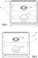
- Fig. 1 illustrates a top view of a conventional component 10 in the form of an oven cavity top formed from a metal sheet in a pressing or deep drawing process and provided with an enamel layer after forming.
- the oven cavity top of Fig.1 is roughly rectangular, wherein the upper edge 10.1 of the component 10 as shown in Fig. 1 corresponds to the upper back edge of the oven cavity and the lower edge 10.2 of the component 10 as shown in Fig. 1 corresponds to the upper front edge of the oven cavity.
- the component 10 comprises several functional structures F1 and F2 generated from the planar metal sheet by pressing and/or punching steps.
- Functional structure F1 is configured to support an oven lamp (not shown) in a wall portion F1.1 that is slightly inclined so that the oven lamp introduced through the opening F1.2 is directed downwards and to a back wall of the oven cavity in order not to shine directly into the eyes of an operator opening the oven door.
- Functional structure F2 relates to a vent for introducing steam into the oven cavity.
- the component also comprises several large bent and/or embossed structures S which only have the function to increase the stiffness of the component so that it does not unintentionally snap or deform e.g. when the component is subjected to high temperatures during the enameling step and/or during operation of the oven.
- these structures S can be dispensed with, if desired, or they can be made smaller, as the required stiffness can be ensured by providing a regular arrangement of micro-indentations in suitable regions R as illustrated in the embodiments shown in Figs. 2 and 3 . It is noted that due to their size and the fact that they can be covered by an enamel layer, the micro-indentations are not visible in these figures.
- Figures 4 and 5 show photographs of a component 10 according to a further embodiment of the invention at different magnification levels.
- the component 10 comprises a macroscopic embossed or bent structure F3 in particular in the edge region thereof, as well as several holes H1-H2 obtained e.g. by punching.
- micro-indentations 14 on the sheet metal surface 12s1 are clearly visible, the arrangement extending substantially over the entire surface of the component.
- the micro-indentations are arranged in a square lattice pattern.
- a similar pattern of micro-protrusions 15 is provided on the surface 12s1 in a staggered configuration with respect to the pattern of micro-indentations 14 resulting overall in a centered square pattern of micro-indentations 14 and micro-protrusions 15 which is most clearly visible in Fig. 5 .
- the dimensions of the micro-indentations can in particular be in the same order of magnitude as the thickness of the sheet metal part of the component.
- Fig. 6 is a schematic and simplified drawing of a conventional component 10 comprising a macroscopic embossed or bent structure F4 for obtaining a desired stiffness of the component.
- a cutout H3 obtained e.g. by laser cutting can be provided in a planar part of the structure as illustrated, but providing such a cutout in the area indicated by H4 might not be possible or might at least require that the cutout is obtained before the embossing step generating the structure F4.
- a cutout can be provided at any desired position such as indicated by way of example in the area indicated in dashed-dotted lines and referenced as H5, even after the micro-protrusions have been provided.
- Fig. 7 is a simplified schematic top view of a portion of a component according to an embodiment of the invention
- Fig. 8 is a cross-sectional view of a part of the subject-matter of Fig. 7 along the line VIII-VIII in Fig. 7
- Fig. 9 is a cross-sectional view of a part of the subject-matter of Fig. 7 along the line IX-IX in Fig. 7 .
- micro-indentations 14 (shown in continuous lines) and micro-protrusions 15 (shown in dashed lines) are also provided in this embodiment in two square lattice patterns that are staggered with respect to each other.
- the micro-protrusions 15 on the sheet metal surface 12s1, 12s2 result from micro-indentations 14 provided on the respective opposed metal sheet surface 12s2, 12s1. Furthermore, in the illustrated example, the shape of the micro-indentations 14 is roughly that of a semi-sphere.
- each micro-indentation 14 perpendicular to the sheet metal surface 12sland the sheet metal thickness t of the sheet metal part 12 are linked by the following relation: d ⁇ 0,4 ⁇ t
- the dimensions l, w (i.e. length and widh) of each micro indentation 14 along the sheet metal surface 12s1 are not larger than 1 cm, preferably in the order of several Millimeters, below 5 mm or even below 1 mm.
- the dimensions l, w of each micro indentation 14 along the sheet metal surface 12s1 are linked to the sheet metal thickness t by the following relations; l ⁇ 10 ⁇ t and w ⁇ 10 ⁇ t and preferably by l ⁇ 2 ⁇ t and w ⁇ 2 ⁇ t
- the distance D between any two adjacent micro indentations 14 provided in the same sheet metal surface as illustrated in Fig. 8 can be larger than the dimensions l, w of those micro indentations 14 in at least one direction, preferably in all directions along the sheet metal surface 12.
- the distance D is to be understood as the dimension of the planar part of the sheet metal surface 12s1 extending between the adjacent micro indentations 14 as illustrated in Fig. 8 .
- Figs. 10 to 13 illustrate in a schematic and simplified manner subsequent steps of a method according to an embodiment of the invention using a pressing tool 20 also according to an embodiment of the invention.
- a sheet metal 11 is provided and arranged between opposing pressing jaws 21 of the pressing tool 20.
- the sheet metal 11 is then pressed between the pressing jaws 21 in order to form the sheet metal part 12 of the component 10.
- Semi-spherical micro-stamps 24 can be provided in a regular arrangement on both pressing jaw surfaces 21s in order to create the micro-indentations 14, and the material of the metal sheet 11 displaced by these micro-stamps 24 is accommodated in corresponding micro-recesses 25 provided on the respective other pressing jaw surfaces 21s, resulting in the regular arrangement of micro-protrusions 15 on both sheet metal surfaces 12s1, 12s2 of the sheet metal part 12 of the component 10.
- pressing jaws of all pressing tools as illustrated herein usually comprise additional larger protrusions and/or depressions used to give the sheet metal part 12 of the component 10 its overall three-dimensional shape, but for reasons of simplicity, these larger structures are not illustrated here.
- the sheet metal part 12 as illustrated in Fig. 12 is then provided on one surface 12s1 thereof with an enamel layer 16 partially or even completely filling the micro-indentations 14 and partially or even completely covering the micro-protrusions 15 on this surface 12s1 as illustrated in Fig. 13 . Both a conventional and a direct enameling process can be used.
- FIG. 14 to 17 A similar manufacturing method using a slightly different pressing tool 20 is shown in Figs. 14 to 17 .
- the pressing tool of Figs. 14 and 15 mainly differs from that of Figs. 10 and 11 in that only the upper pressing jaw 21 is provided with an arrangement of micro-stamps 24 and instead of corresponding micro-recesses, a cover layer 28 made from an elastic material such as rubber is provided on the surface of the lower pressing jaw 21, wherein, as illustrated in Fig. 15 , the layer 28 is elastically deformed by the material of the metal sheet 11 displaced by the micro-stamps 14 when the pressing jaws 21 are pressed together.
- each of the two pressing jaws comprises both micro-stamps and elastic cover layer regions in a suitable arrangement to provide both sheet metal surfaces of the component formed in the pressing tools with an arrangement of micro-indentations and micro-protrusions.
- Fig. 18 shows a conventional component 10 in the form of a rectangular baking tray that is known from the prior art.
- the edge region of the component 10 is bent in the usual manner in order to form a peripheral flange F5 as a functional feature.
- bent structures S1 and S2 are provided in the food support area in order to increase the stiffness of the baking tray and to prevent it from snapping when being used at high temperatures.
- Fig. 19 shows a component 10 according to an embodiment of the invention which mainly differs from the example of Fig. 18 in that in addition to the large bent structures S1 and S2, a regular arrangement of micro-indentations as described above are provided in the region R which has the form of a rectangular ring in this embodiment.
- the stiffness of the component 10 is further increased, so that the tray can be used at even higher temperatures and/or can support even heavier load.
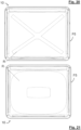
- Figs. 20 and 21 illustrate further examples of different regions R where the regular arrangement of micro-indentations might be provided on a baking tray.
- the larger bent structures S1, S2 are not present in these embodiments as they are effectively substituted by the micro-indentations.
- the entire food support area of a tray receives the micro-indentations in order to increase its stiffness for taking up heavy food.
- the invention allows to obtain components for domestic appliances formed from sheet metal so that the components meet the respective stiffness requirements while keeping the component surface as flat and smooth as possible or desired.
Landscapes
- Engineering & Computer Science (AREA)
- Mechanical Engineering (AREA)
- Chemical & Material Sciences (AREA)
- Combustion & Propulsion (AREA)
- General Engineering & Computer Science (AREA)
- Shaping Metal By Deep-Drawing, Or The Like (AREA)
Abstract
Description
- The present invention relates to a component of a domestic appliance such as for example an oven cavity or a baking tray, wherein a sheet metal part of the component is formed from a sheet metal, in particular in a pressing or deep-drawing process.
- According to other aspects, the invention also relates to a pressing tool and to a manufacturing method for such components.
- In the prior art, these components often have large and clearly visible embossments and/or bent structures the only function of which is to increase the stiffness of the component as stress is created in the material.
- In
DE 7516419 U for example, which discloses a component with the features of the preamble part ofclaim 1, the side walls and the top wall of the inner cavity of a dishwasher made by expanding an annular metal sheet jacket are stiffened by embossed bead-like indentations in the form of a waffle structure. - The need for increasing the stiffness in particular occurs for components which are to be enameled after being formed as the enameling process, which runs at temperatures over 800°C, would otherwise deform the components and make them unusable.
- However, there are cases in which it is preferred that a surface of the component is as flat and smooth as possible, both for optical and for practical reasons, e.g. as a smooth and flat surface can be cleaned more easily than a surface with a lot of embossments or other deformations.
- According to the above, the object of the present invention is to improve a compromise between stiffness and surface flatness for components of domestic appliances made from sheet metal.
- This object is solved, according to the invention, by providing a regular arrangement of micro-indentations on at least one sheet metal surface of the sheet metal part of the component, wherein each micro-indentation has a depth perpendicular to the sheet metal surface of not less than 40% of a sheet metal thickness of the sheet metal part.
- It is noted that in this application, the term "micro-indentation" is to be understood as relating to small indentations, i.e. to indentations having dimensions along the sheet metal surface of not more than 1 cm, preferably in the order of several Millimeters, below 5 mm or even below 1 mm.
- The inventors have found that a regular arrangement of such micro-indentations can nevertheless considerably improve the stiffness of the resulting component so that larger embossed structures provided for stiffness reasons in the prior art can be dispensed with, if desired.
- However, the micro-indentations do not necessarily need to completely replace the standard embossed structures. They also could be provided in addition in order to increase the stiffness even further, or the conventional embossed structures could be made smaller or could be provided in a smaller region, avoiding such the bigger deep-drawing radius of the prior art. Furthermore, the overall thickness of the component could be reduced while maintaining its stiffness, yielding both energy and cost benefits.
- Preferably, the micro-indentations are all identical or can be categorized into several groups, all micro-indentations of each group being identical and the micro-indentations of different groups being different e.g. in size and/or form.
- According to a particular embodiment, a dimension of each micro-indentation in at least one direction along the sheet metal surface, preferably in all directions along the sheet metal surface, is not larger than ten times the sheet metal thickness, preferably not larger than five times, more preferably not larger than twice and most preferably not larger than once the sheet metal thickness.
- In addition or as an alternative, a distance between any two adjacent micro-indentations in the same sheet metal surface, can be larger than the dimension of each of those adjacent micro-indentations in at least one direction along the sheet metal surface, preferably in all directions along the sheet metal surface.
- Preferably, the distance between any two adjacent micro-indentations in the same sheet metal surface is two times larger, more preferably five times larger than the dimension of each of those two micro-indentations in at least one direction along the sheet metal surface, preferably in all directions along the sheet metal surface.
- In this manner, the overall impression of the component surface is still that of a mainly flat surface, and it furthermore facilitates cleaning.
- It is noted that the component surface can be but is not necessarily identical to the sheet metal surface, in particular because the component can comprise a further layer covering the sheet metal surface as will be explained in more detail below.
- For many practical purposes, the thickness of the sheet metal part of the component can be substantially constant. If this is not the case, the term "sheet metal thickness" is to be understood as referring to the average thickness of the sheet metal part, either over the entire region of the sheet metal part or limited to a region comprising the arrangement of micro-indentations.
- According to a preferred embodiment of the invention, the component further comprises at least one enamel layer that is preferably provided on the sheet metal surface provided with the arrangement of micro-indentations and which even more preferably partially or completely fills and hides the micro-indentations, thus resulting in a very flat and smooth surface that is both optically pleasing and easily cleanable. This is especially preferable for oven components.
- The sheet metal thickness of the sheet metal part of the component with or without the enamel layer can be in a range from 0.3 mm to 0.8 mm, preferably from 0.4 mm to 0.7 mm and more preferably still from 0.5 mm to 0.6 mm.
- The enamel layer thickness of a one-time enameled surface is typically in a range of 80 µm to 200 µm. Some components such as e.g. the oven cavity of a steam oven can receive two or more enamel layers to increase the resistance to corrosion.
- The sheet metal used for the component is preferably a cold-rolled steel sheet, in particular a cold-rolled steel sheet for enameling such as DC04ED, DC03ED, DC04EK or DC06EK according to DIN EN 10209 e.g. in the version of September 2013.
- It is noted that the invention can support a change from ED materials with direct enameling (e.g. DC04ED) to EK materials with conventional enameling (e.g. DC04EK or DC06EK). As EK material provides less form stability during the firing process, the micro-indentations could help to stiffen and stabilize local areas.
- Depending on the geometry and the intended purpose of the component, the regular arrangement of micro-indentations can extend over substantially the entire sheet metal surface of the sheet metal part of the component, e.g. over more than 80% or 90% of the sheet metal surface, or the arrangement of micro-indentations can be provided only in one or several defined local areas of the surface of the sheet metal part of the component, in particular in those areas with increased stiffness requirements.
- The inventors have found that the stiffness of the component can be reliably increased when the dimensions of the micro-indentations are chosen in such a manner that each micro-indentation in one metal sheet surface results in a corresponding small "micro-protrusion" in the opposed sheet metal surface. Therefore, according to a preferred embodiment of the invention, a regular arrangement of micro-protrusions is provided on a sheet metal surface of the sheet metal part that is opposed to the sheet metal surface provided with the regular arrangement of micro-indentations, each micro-protrusion corresponding in position and form to one of the micro-indentations.
- In case an enamel layer is provided on the sheet metal surface provided with the micro-protrusions, it preferably completely covers and hides also these micro-protrusions, so that the resulting outer surface of the component is flat and smooth.
- In order to ensure that the stiffness is increased evenly over the intended region, the micro-indentations can be arranged in the form of a regular two-dimensional lattice, in particular in the form of a rectangular, square or hexagonal lattice.
- More uniform bending properties and higher stiffness can be obtained when both opposing sheet metal surfaces of the sheet metal part of the component are provided with a regular arrangement of micro-indentations as defined above.
- Preferably, the micro-indentations on the two opposing sheet metal surfaces are arranged in a staggered configuration with respect to each other, in particular when each micro-indentation on one sheet metal surface results in a corresponding micro-protrusion on the opposing surface so that each metal sheet surface is provided with a regular pattern of both micro-indentations and micro-protrusions.
- A good compromise between stiffness properties and surface smoothness can be obtained when the depth of the micro-indentations is from 40% to 100% of the sheet metal thickness.
- However, deeper indentations should not be excluded. For example, the depth of the micro-indentations could be up to 200%, in particular up to 150% and preferably up to 120% of the sheet metal thickness of the sheet-metal portion, even if in some cases this means that the micro-indentations are more visible and in the case of an enameled component possibly cannot be covered or filled completely.
- As the micro-indentations are generated in a pressing or embossing process, they should taper toward the bottom so that the component can be easily removed from the corresponding pressing tool. The shape of the micro-indentations can for example be the negative shape of a cone, e.g. a circular or elliptic one, or a pyramid or a spherical cap, in particular a semi-sphere which can all be easily realized with correspondingly shaped small stamps provided on a pressing tool.
- The present inventions applies to in particular to ovens such as pyro-ovens, non-pyro ovens, steam ovens and microwave ovens, but can also apply to other household appliances such as washing machines, dishwashers etc.
- In particular, the domestic appliance can be an oven and the component can be selected from the group consisting of a cavity, a front frame, a fan cover, an oven accessory, and an outer housing component.
- The oven accessory can be for example a baking tray or a pan, and the outer housing component can be e.g. a bottom, a side panel, a rear panel, a top panel or a component carrier.
- According to another aspect of the invention, the object is solved by a pressing tool comprising two opposing pressing jaws, e.g. a punch and a die, configured to cooperate in order to form a sheet metal part of a component of a domestic appliance, in particular a component according to any of the preceding claims, wherein at least one of the pressing jaws comprises a jaw surface portion provided with a regular arrangement of protruding micro-stamps, each micro-stamp having a height perpendicular to the surface portion of not less than 40 % of a sheet metal thickness of a sheet metal part of the component formed in the tool and preferably having dimensions along the surface portion of not more than ten times the sheet metal thickness, more preferably of not more than five times, twice or once the sheet metal thickness.
- Similar to the term "micro-protrusion", the term "micro-stamp" is to be understood as relating to small stamps, i.e. to stamps having dimensions along the jaw surface portion of not more than 1 cm, preferably in the order of several Millimeters, below 5 mm or even below 1 mm
- In particular or as an alternative, considering that the sheet metal thickness of the sheet metal part of the component usually is in a range from 0.3 mm to 0.8 mm the height h of the micro-stamps can be equal to or larger than 0.012 mm (=0.4*0.3mm) and the dimensions of the micro-stamps along the jaw surface portions can be equal to or smaller than 8 mm (= 10*0.8 mm), 4 mm, 1.6 mm (= 2*0.8 mm) or 0.8 mm.
- In such a pressing tool, both the overall three-dimensional form of the component and the micro-indentations can be generated in a single pressing process. By producing those micro-indentations, the material also gets stressed and the structure gets stiffened without having distinctive macroscopic embossments and a non-continuous surface.
- Some or all of the structures for generating embossments and bent structures provided in the conventional pressing tools only in order to increase the component stiffness can be dispensed with in the pressing tool according to the invention, because these embossments or bent structures are effectively substituted by the micro-indentations of the present invention.
- The micro-stamps can be provided in the complete area of the components or only in defined areas depending on the areas of the final components that require stiffening.
- If the micro-indentations are introduced as part of a pressing step in the generation of the components as mentioned above, it can be determined in dependency of the further requirements of the tooling set on which of the opposing metal sheet surfaces the micro-indentations shall be applied.
- Preferably, the pressing jaw opposing that pressing jaw provided with the regular arrangement of micro-stamps can comprise a regular arrangement of micro-recesses, each micro-recess corresponding in form and position to one of the micro-stamps, so that the sheet material displaced by each micro-stamp can be accommodated in the corresponding micro-recess.
- As an alternative, the pressing jaw opposing that pressing jaw provided with the regular arrangement of micro-stamps can comprise a cover layer made from an elastic material, the cover layer being provided in those regions of the pressing jaw surface opposing the micro-stamps when the pressing jaws are moved towards each other and wherein the cover layer is configured to be elastically deformed by the sheet metal material displaced by the micro-stamps.
- The individual micro-stamps or "spikes" can e.g. have the form of cones, e.g. circular or elliptic cones, pyramids or spherical caps, in particular semi-spheres.
- According to yet a further aspect of the invention, the object is solved by a manufacturing method for a component of a domestic appliance, in particular for a component according to the invention as defined above, the method comprising the following steps:
- providing a sheet metal,
- pressing the sheet metal in order to form a sheet metal part of the component, and
- generating, on at least one sheet metal surface of the sheet metal part, an arrangement of micro-indentations, each micro-indentation having a depth perpendicular to the sheet metal surface of not less than 40 % of a sheet metal thickness of the sheet metal part and preferably having dimensions along the sheet metal surface of not more than ten times the sheet metal thickness, preferably of not more than five times, twice or once the sheet metal thickness.
- The micro-indentations can be introduced during the pressing step in which also the overall macroscopic form of the component is defined, or they can be introduced in a separate step before or after the step of pressing the metal sheet.
- According to a preferred embodiment, the method further comprises a step of providing an enamel layer on at least one surface of the component, preferably that surface on which the arrangement of micro-indentations is provided.
- In order to obtain a smooth surface, the resulting enamel layer can be provided in such a manner that it partially or completely fills the micro-indentations and preferably also partially or completely covers and hides any micro-protrusions if those are provided.
- However, the invention is also applicable to non-enameled components, e.g. chassis components like a top panel or a back panel, made from a material such as galvanized or micro-alloyed steel sheets, e.g. DX52 or HX300LAD.
- In conventional components in which the required stiffness is achieved by large embossed or bent structures, the thickness of the component can be locally increased to such an extent that e.g. laser cutting the component across such a structure becomes difficult or impossible.
- As this problem is eliminated when the stiffness of the component is increased by the regular arrangement of micro-indentations instead of the conventional large embossed or bent structures, the method preferably comprises a step of cutting, preferably laser cutting the component across a region in which the arrangement of micro-indentations is provided.
- In the following, the present invention is explained in more detail with reference to some preferred embodiments of the invention and comparative examples as illustrated in the accompanying figures.
-
Fig. 1 shows a comparative example of a conventional oven cavity top from the prior art, -
Figs. 2 and 3 show two embodiments of the invention in the form of oven cavity tops with micro-indentations. -
Figs. 4 and 5 show photos of a further embodiment of the invention at different magnification levels which in particular show the geometric arrangement of the micro-indentations, -
Fig. 6 is a simplified schematic drawing illustrating the problem of placing cutouts in conventional components, -
Fig. 7 is a simplified schematic top view of a portion of a component according to an embodiment of the invention, -
Fig. 8 is a cross-sectional view of a part of the subject-matter ofFig. 7 along the line VIII-VIII inFig. 7 -
Fig. 9 is a cross-sectional view of a part of the subject-matter ofFig. 7 along the line IX-IX inFig. 7 . -
Figs. 10 to 13 schematically illustrate steps of a manufacturing method according to an embodiment of the invention in a pressing tool according to an embodiment of the invention, -
Figs. 14 to 17 schematically illustrate steps of a manufacturing method according to an embodiment of the invention in a modified pressing tool according to another embodiment of the invention. -
Fig. 18 illustrates a conventional baking tray as known from the prior art, and -
Figs. 19 to 21 illustrate different examples of baking trays according to embodiments of the present invention. - Corresponding features of different embodiments are denoted by the same reference signs in the figures illustrating these embodiments. Furthermore, for clarity reasons, if several identical features are present in one figure, only some of them are denoted by reference signs. In a similar manner, not all features are denoted by reference signs in each figure, but mainly those reference signs necessary or helpful for explaining the respective figure are included,
- Furthermore, it is to be noted that
Figs. 14 to 17 are simplified and schematic illustrations that are used mainly to illustrate some principle ideas of the invention and that are in particular not drawn to scale, unless indicated otherwise. -
Fig. 1 illustrates a top view of aconventional component 10 in the form of an oven cavity top formed from a metal sheet in a pressing or deep drawing process and provided with an enamel layer after forming. - The oven cavity top of
Fig.1 is roughly rectangular, wherein the upper edge 10.1 of thecomponent 10 as shown inFig. 1 corresponds to the upper back edge of the oven cavity and the lower edge 10.2 of thecomponent 10 as shown inFig. 1 corresponds to the upper front edge of the oven cavity. - The
component 10 comprises several functional structures F1 and F2 generated from the planar metal sheet by pressing and/or punching steps. - Functional structure F1 is configured to support an oven lamp (not shown) in a wall portion F1.1 that is slightly inclined so that the oven lamp introduced through the opening F1.2 is directed downwards and to a back wall of the oven cavity in order not to shine directly into the eyes of an operator opening the oven door.
- Functional structure F2 relates to a vent for introducing steam into the oven cavity.
- In addition to these functional features, the component also comprises several large bent and/or embossed structures S which only have the function to increase the stiffness of the component so that it does not unintentionally snap or deform e.g. when the component is subjected to high temperatures during the enameling step and/or during operation of the oven.
- According to the invention, these structures S can be dispensed with, if desired, or they can be made smaller, as the required stiffness can be ensured by providing a regular arrangement of micro-indentations in suitable regions R as illustrated in the embodiments shown in
Figs. 2 and 3 . It is noted that due to their size and the fact that they can be covered by an enamel layer, the micro-indentations are not visible in these figures. -
Figures 4 and 5 show photographs of acomponent 10 according to a further embodiment of the invention at different magnification levels. Thecomponent 10 comprises a macroscopic embossed or bent structure F3 in particular in the edge region thereof, as well as several holes H1-H2 obtained e.g. by punching. - Furthermore, the regular arrangement of micro-indentations 14 on the sheet metal surface 12s1 is clearly visible, the arrangement extending substantially over the entire surface of the component. The micro-indentations are arranged in a square lattice pattern. Furthermore, a similar pattern of micro-protrusions 15 is provided on the surface 12s1 in a staggered configuration with respect to the pattern of micro-indentations 14 resulting overall in a centered square pattern of micro-indentations 14 and
micro-protrusions 15 which is most clearly visible inFig. 5 . - As shown in the figures, the dimensions of the micro-indentations can in particular be in the same order of magnitude as the thickness of the sheet metal part of the component.
-
Fig. 6 is a schematic and simplified drawing of aconventional component 10 comprising a macroscopic embossed or bent structure F4 for obtaining a desired stiffness of the component. A cutout H3 obtained e.g. by laser cutting can be provided in a planar part of the structure as illustrated, but providing such a cutout in the area indicated by H4 might not be possible or might at least require that the cutout is obtained before the embossing step generating the structure F4. - In a component according to the invention such as illustrated in
Fig. 7 however, wherein the desired stiffness is imparted by the regular arrangement of micro indentations and no macroscopic bent or embossed structure is required, a cutout can be provided at any desired position such as indicated by way of example in the area indicated in dashed-dotted lines and referenced as H5, even after the micro-protrusions have been provided. -
Fig. 7 is a simplified schematic top view of a portion of a component according to an embodiment of the invention, whileFig. 8 is a cross-sectional view of a part of the subject-matter ofFig. 7 along the line VIII-VIII inFig. 7 and Fig. 9 is a cross-sectional view of a part of the subject-matter ofFig. 7 along the line IX-IX inFig. 7 . - Similar to
Figs. 4 to 5 , the micro-indentations 14 (shown in continuous lines) and micro-protrusions 15 (shown in dashed lines) are also provided in this embodiment in two square lattice patterns that are staggered with respect to each other. - As illustrated in
Figs. 8 and 9 , the micro-protrusions 15 on the sheet metal surface 12s1, 12s2 result frommicro-indentations 14 provided on the respective opposed metal sheet surface 12s2, 12s1. Furthermore, in the illustrated example, the shape of the micro-indentations 14 is roughly that of a semi-sphere. - According to the invention, the depth d of each micro-indentation 14 perpendicular to the sheet metal surface 12sland the sheet metal thickness t of the
sheet metal part 12 are linked by the following relation:
- Furthermore, according to the invention, the dimensions l, w (i.e. length and widh) of each
micro indentation 14 along the sheet metal surface 12s1 are not larger than 1 cm, preferably in the order of several Millimeters, below 5 mm or even below 1 mm. - According to a preferred embodiment, the dimensions l, w of each
micro indentation 14 along the sheet metal surface 12s1 are linked to the sheet metal thickness t by the following relations;

- Moreover, the distance D between any two adjacent
micro indentations 14 provided in the same sheet metal surface as illustrated inFig. 8 can be larger than the dimensions l, w of thosemicro indentations 14 in at least one direction, preferably in all directions along thesheet metal surface 12. In this context, it is noted that the distance D is to be understood as the dimension of the planar part of the sheet metal surface 12s1 extending between the adjacentmicro indentations 14 as illustrated inFig. 8 . -
Figs. 10 to 13 illustrate in a schematic and simplified manner subsequent steps of a method according to an embodiment of the invention using apressing tool 20 also according to an embodiment of the invention. - First, as illustrated in
Fig. 10 , asheet metal 11 is provided and arranged between opposingpressing jaws 21 of thepressing tool 20. - As illustrated in
Fig. 11 , thesheet metal 11 is then pressed between thepressing jaws 21 in order to form thesheet metal part 12 of thecomponent 10. - Semi-spherical micro-stamps 24 can be provided in a regular arrangement on both pressing jaw surfaces 21s in order to create the micro-indentations 14, and the material of the
metal sheet 11 displaced by these micro-stamps 24 is accommodated in corresponding micro-recesses 25 provided on the respective otherpressing jaw surfaces 21s, resulting in the regular arrangement of micro-protrusions 15 on both sheet metal surfaces 12s1, 12s2 of thesheet metal part 12 of thecomponent 10. - It is noted that the pressing jaws of all pressing tools as illustrated herein usually comprise additional larger protrusions and/or depressions used to give the
sheet metal part 12 of thecomponent 10 its overall three-dimensional shape, but for reasons of simplicity, these larger structures are not illustrated here. - The
sheet metal part 12 as illustrated inFig. 12 is then provided on one surface 12s1 thereof with anenamel layer 16 partially or even completely filling the micro-indentations 14 and partially or even completely covering the micro-protrusions 15 on this surface 12s1 as illustrated inFig. 13 . Both a conventional and a direct enameling process can be used. - A similar manufacturing method using a slightly different pressing
tool 20 is shown inFigs. 14 to 17 . The pressing tool ofFigs. 14 and 15 mainly differs from that ofFigs. 10 and 11 in that only the upperpressing jaw 21 is provided with an arrangement ofmicro-stamps 24 and instead of corresponding micro-recesses, acover layer 28 made from an elastic material such as rubber is provided on the surface of the lowerpressing jaw 21, wherein, as illustrated inFig. 15 , thelayer 28 is elastically deformed by the material of themetal sheet 11 displaced by the micro-stamps 14 when thepressing jaws 21 are pressed together. - It is of course also possible that each of the two pressing jaws comprises both micro-stamps and elastic cover layer regions in a suitable arrangement to provide both sheet metal surfaces of the component formed in the pressing tools with an arrangement of micro-indentations and micro-protrusions.
-
Fig. 18 shows aconventional component 10 in the form of a rectangular baking tray that is known from the prior art. The edge region of thecomponent 10 is bent in the usual manner in order to form a peripheral flange F5 as a functional feature. - Furthermore large bent structures S1 and S2 are provided in the food support area in order to increase the stiffness of the baking tray and to prevent it from snapping when being used at high temperatures.
-
Fig. 19 shows acomponent 10 according to an embodiment of the invention which mainly differs from the example ofFig. 18 in that in addition to the large bent structures S1 and S2, a regular arrangement of micro-indentations as described above are provided in the region R which has the form of a rectangular ring in this embodiment. - Due to the micro-indentations, the stiffness of the
component 10 is further increased, so that the tray can be used at even higher temperatures and/or can support even heavier load. - Due to the micro-indentations in addition to structures S1 and S2, it might also be possible to reduce the overall material thickness in comparison to the conventional example of
Fig. 18 while maintaining the component stiffness. -
Figs. 20 and 21 illustrate further examples of different regions R where the regular arrangement of micro-indentations might be provided on a baking tray. In contrast toFig. 19 , the larger bent structures S1, S2 are not present in these embodiments as they are effectively substituted by the micro-indentations. - Furthermore, it is also possible that the entire food support area of a tray receives the micro-indentations in order to increase its stiffness for taking up heavy food.
- Overall, the invention allows to obtain components for domestic appliances formed from sheet metal so that the components meet the respective stiffness requirements while keeping the component surface as flat and smooth as possible or desired.
Claims (17)
- A component (10) of a domestic appliance;
wherein a sheet metal part (12) of the component (10) is formed from a sheet metal (11), characterized in that a regular arrangement of micro-indentations (14) is provided on at least one sheet metal surface (12s1, 12s2) of the sheet metal part (12), each micro-indentation (14) having a depth (d) perpendicular to the sheet metal surface (12s1, 12s2) of not less than 40 % of a sheet metal thickness (t) of the sheet metal part (12). - The component (10) according to claim 1,
wherein a dimension of each micro-indentation (14) in at least one direction along the sheet metal surface (12s1, 12s2) is not larger than ten times the sheet metal thickness (t), preferably not larger than five times, more preferably not larger than twice and most preferably not larger than once the sheet metal thickness (t). - The component (10) according to claim 1 or 2,
wherein a distance between any two adjacent micro-indentations (14) in the same sheet metal surface(12s1, 12s2) is larger than the dimensions of those adjacent micro-indentations in at least one direction along the sheet metal surface (12s1, 12s2). - The component (10) according to any of the preceding claims, further comprising at least one enamel layer (16) that is preferably provided on the sheet metal surface (12s1) provided with the arrangement of micro-indentations (14) and which even more preferably completely fills the micro-indentations (14).
- The component (10) according to any of the preceding claims,
wherein a regular arrangement of micro-protrusions (15) is provided on a sheet metal surface (12s2, 12s1) of the sheet metal part (12) opposed to the sheet metal surface (12s1, 12s2) provided with the regular arrangement of micro-indentations (14), each micro-protrusion (15) corresponding in position and form to one of the micro-indentations (14). - The component (10) according to any of the preceding claims, wherein the micro-indentations (14) are arranged in the form of a regular two-dimensional lattice, in particular in the form of a rectangular, square or hexagonal lattice.
- The component (10) according to any of the preceding claims, wherein each of two opposing sheet metal surfaces (12s1, 12s2) of the sheet metal part (12) is provided with an arrangement of micro-indentations (14), each micro-indentation (14) having a depth (d) perpendicular to the associated sheet metal surface (12s1, 12s2) of not less than 40 % of the sheet metal thickness (t) and preferably having dimensions (l, w) along the associated sheet metal surface (12s1, 12s2) of not more than ten times the sheet metal thickness (t), more preferably of not more than five times, twice or once the sheet metal thickness (t).
- The component (10) according to claim 7,
wherein the arrangements of micro-indentations (14) provided on the two opposing sheet metal surfaces (12s1, 12s2) are arranged in a staggered configuration with respect to each other. - The component (10) according to any of the preceding claims, wherein the depth (d) of the micro-indentations (14) is not larger than 200 % of the sheet metal thickness (t), in particular not larger than 150 %, preferably not larger than 120 % and more preferably not larger than 100 % of the sheet metal thickness (t) .
- The component (10) according to any of the preceding claims, wherein the micro-indentations (14) have the negative shape of a cone or a pyramid or a spherical cap, in particular a semi-sphere.
- The component (10) according to any of the preceding claims, in particular according to claim 4, wherein the domestic appliance is an oven, and wherein the component (10) is selected from the group consisting of: a cavity, a front frame, a fan cover, an oven accessory and a housing component.
- A pressing tool (20) comprising two opposing pressing jaws (21) configured to cooperate in order to form a sheet metal part (12) of a component (10) of a domestic appliance, in particular a component according to any of the preceding claims,
characterized in than at least one of the jaws (21) comprises a jaw surface portion (21s) provided with a regular arrangement of protruding micro-stamps (24), each micro-stamp having a height (h) perpendicular to the jaw surface portion of not less than 40 % of a sheet metal thickness (t) of the sheet metal part (12) formed in the tool (20) and each micro-stamp preferably having dimensions (L) along the jaw surface portion (21) of not more than ten times the sheet metal thickness (t), more preferably of not more than five times, twice or once the sheet metal thickness (t) . - A pressing tool (20) according to claim 10, wherein the pressing jaw (21) opposing that pressing jaw (21) provided with the regular arrangement of micro-stamps (24) comprises a regular arrangement of micro-recesses (25), each micro-recess (25) corresponding in form and position to one of the micro-stamps (24), or wherein the pressing jaw (21) opposing that pressing jaw (21) provided with the regular arrangement of micro-stamps (24) comprises a cover layer made from an elastic material.
- A manufacturing method for a component (10) of a domestic appliance, in particular a component according to any of claims 1 to 11, the method comprising the following steps:providing a sheet metal (11);pressing the sheet metal (11) in order to form a sheet metal part (12) of the component (10);characterized in that the method furthermore comprises the following step:
generating, on at least one sheet metal surface (12s1) of the sheet metal part, (12) an arrangement of micro-indentations (14), each micro-indentation (14) having a depth (d) perpendicular to the sheet metal surface (12s1, 12s2) of not less than 40 % of a sheet metal thickness (t) of the sheet metal part (12) and preferably having dimensions (l, w) along the sheet metal surface (12s1, 12s2) of not more than ten times the sheet metal thickness (t), preferably of not more than five times, twice or once the sheet metal thickness (t). - The method according to claim 13, wherein the arrangement of micro-indentations (14) is generated during the step of pressing the metal sheet (10), or wherein the arrangement of micro-indentations (14) is generated in a separate step before or after the step of pressing the metal sheet (10).
- Method according to any of the preceding method claims, further comprising a step of providing an enamel layer (16) on at least one surface (12s1) of the sheet metal part (12), preferably that surface on which the arrangement of micro-indentations (14) is provided, most preferably in such a manner that the enamel layer (16) completely fills the micro-indentations (14)
- Method according to any of the preceding method claims, further comprising a step of cutting, preferably laser-cutting, the component (10) across a region (R) in which the arrangement of micro-indentations (14) is provided.
Priority Applications (5)
| Application Number | Priority Date | Filing Date | Title |
|---|---|---|---|
| EP22188850.6A EP4316683A1 (en) | 2022-08-04 | 2022-08-04 | Component of a domestic appliance comprising micro-indentations, pressing tool and manufacturing method for the component |
| PCT/EP2023/069374 WO2024028057A1 (en) | 2022-08-04 | 2023-07-12 | Component of a domestic appliance comprising micro-indentations, pressing tool and manufacturing method for the component |
| CN202380054257.2A CN119562870A (en) | 2022-08-04 | 2023-07-12 | Part of a household appliance comprising micro-dimples, pressing tool and manufacturing method for the part |
| AU2023318457A AU2023318457A1 (en) | 2022-08-04 | 2023-07-12 | Component of a domestic appliance comprising micro-indentations, pressing tool and manufacturing method for the component |
| US19/100,684 US20260042134A1 (en) | 2022-08-04 | 2023-07-12 | Component of a domestic appliance comprising micro-indentations, pressing tool and manufacturing method for the component |
Applications Claiming Priority (1)
| Application Number | Priority Date | Filing Date | Title |
|---|---|---|---|
| EP22188850.6A EP4316683A1 (en) | 2022-08-04 | 2022-08-04 | Component of a domestic appliance comprising micro-indentations, pressing tool and manufacturing method for the component |
Publications (1)
| Publication Number | Publication Date |
|---|---|
| EP4316683A1 true EP4316683A1 (en) | 2024-02-07 |
Family
ID=82839187
Family Applications (1)
| Application Number | Title | Priority Date | Filing Date |
|---|---|---|---|
| EP22188850.6A Pending EP4316683A1 (en) | 2022-08-04 | 2022-08-04 | Component of a domestic appliance comprising micro-indentations, pressing tool and manufacturing method for the component |
Country Status (5)
| Country | Link |
|---|---|
| US (1) | US20260042134A1 (en) |
| EP (1) | EP4316683A1 (en) |
| CN (1) | CN119562870A (en) |
| AU (1) | AU2023318457A1 (en) |
| WO (1) | WO2024028057A1 (en) |
Cited By (1)
| Publication number | Priority date | Publication date | Assignee | Title |
|---|---|---|---|---|
| WO2026050226A1 (en) * | 2024-08-26 | 2026-03-05 | Meta Platforms Technologies, Llc | Increasing strength in a metal sheet |
Citations (11)
| Publication number | Priority date | Publication date | Assignee | Title |
|---|---|---|---|---|
| DE2014936A1 (en) * | 1969-03-28 | 1970-10-08 | Zealand Eng Co Ltd | Metal tile and process for its manufacture |
| US3783853A (en) * | 1972-05-30 | 1974-01-08 | Gen Electric | Textured continuous cleaning surface for cooking ovens |
| DE7516419U (en) | 1975-05-23 | 1976-03-04 | Bosch-Siemens Hausgeraete Gmbh, 7000 Stuttgart | CONTAINERS, IN PARTICULAR FOR FRONT-SIDED DISHWASHING MACHINES |
| CA2239525A1 (en) * | 1997-09-23 | 1999-03-23 | Newell Operating Company | Bakeware with patterned surface texture |
| US20060112952A1 (en) * | 2004-11-08 | 2006-06-01 | Steinberg Dan A | Heat shield for preventing bottom surface burning of baked foods |
| EP1872880B1 (en) * | 2006-06-29 | 2009-09-16 | BSH Bosch und Siemens Hausgeräte GmbH | Method and device for embossing a drum cover |
| US20130167828A1 (en) * | 2011-12-28 | 2013-07-04 | Daniel Joseph Trice | Oven rack |
| US8763520B1 (en) * | 2008-02-04 | 2014-07-01 | Richard Jason Sanita | Pyramid pan |
| DE102015224800A1 (en) * | 2015-12-10 | 2017-06-14 | BSH Hausgeräte GmbH | Muffle and household cooker |
| EP1872881B1 (en) * | 2006-06-29 | 2017-10-25 | BSH Hausgeräte GmbH | Method and device for embossing a drum cover |
| EP2053952B1 (en) * | 2006-08-25 | 2019-07-03 | Intellectual Property Development Corporation Pty Ltd | Embossed metal foil |
-
2022
- 2022-08-04 EP EP22188850.6A patent/EP4316683A1/en active Pending
-
2023
- 2023-07-12 WO PCT/EP2023/069374 patent/WO2024028057A1/en not_active Ceased
- 2023-07-12 CN CN202380054257.2A patent/CN119562870A/en active Pending
- 2023-07-12 AU AU2023318457A patent/AU2023318457A1/en active Pending
- 2023-07-12 US US19/100,684 patent/US20260042134A1/en active Pending
Patent Citations (11)
| Publication number | Priority date | Publication date | Assignee | Title |
|---|---|---|---|---|
| DE2014936A1 (en) * | 1969-03-28 | 1970-10-08 | Zealand Eng Co Ltd | Metal tile and process for its manufacture |
| US3783853A (en) * | 1972-05-30 | 1974-01-08 | Gen Electric | Textured continuous cleaning surface for cooking ovens |
| DE7516419U (en) | 1975-05-23 | 1976-03-04 | Bosch-Siemens Hausgeraete Gmbh, 7000 Stuttgart | CONTAINERS, IN PARTICULAR FOR FRONT-SIDED DISHWASHING MACHINES |
| CA2239525A1 (en) * | 1997-09-23 | 1999-03-23 | Newell Operating Company | Bakeware with patterned surface texture |
| US20060112952A1 (en) * | 2004-11-08 | 2006-06-01 | Steinberg Dan A | Heat shield for preventing bottom surface burning of baked foods |
| EP1872880B1 (en) * | 2006-06-29 | 2009-09-16 | BSH Bosch und Siemens Hausgeräte GmbH | Method and device for embossing a drum cover |
| EP1872881B1 (en) * | 2006-06-29 | 2017-10-25 | BSH Hausgeräte GmbH | Method and device for embossing a drum cover |
| EP2053952B1 (en) * | 2006-08-25 | 2019-07-03 | Intellectual Property Development Corporation Pty Ltd | Embossed metal foil |
| US8763520B1 (en) * | 2008-02-04 | 2014-07-01 | Richard Jason Sanita | Pyramid pan |
| US20130167828A1 (en) * | 2011-12-28 | 2013-07-04 | Daniel Joseph Trice | Oven rack |
| DE102015224800A1 (en) * | 2015-12-10 | 2017-06-14 | BSH Hausgeräte GmbH | Muffle and household cooker |
Cited By (1)
| Publication number | Priority date | Publication date | Assignee | Title |
|---|---|---|---|---|
| WO2026050226A1 (en) * | 2024-08-26 | 2026-03-05 | Meta Platforms Technologies, Llc | Increasing strength in a metal sheet |
Also Published As
| Publication number | Publication date |
|---|---|
| CN119562870A (en) | 2025-03-04 |
| US20260042134A1 (en) | 2026-02-12 |
| AU2023318457A1 (en) | 2024-12-19 |
| WO2024028057A1 (en) | 2024-02-08 |
Similar Documents
| Publication | Publication Date | Title |
|---|---|---|
| JP6974911B2 (en) | A cooking container with a partially covered stainless steel inner surface, and a method for its manufacture. | |
| CA2064136C (en) | Article constituted from a plate produced from a relatively soft metal and cooking vessel constituting such an article | |
| US20260042134A1 (en) | Component of a domestic appliance comprising micro-indentations, pressing tool and manufacturing method for the component | |
| JPH05305360A (en) | Method and apparatus for forming embossed parts on a sheet blank and the product obtained thereby | |
| US5809630A (en) | Method of manufacturing a culinary vessel with reinforced bottom | |
| KR102138519B1 (en) | Decor panel for home appliances and apparatus for manufacturing the same | |
| HU224598B1 (en) | Process for the manufacture of cooking vessels and vessels obtained according to such process | |
| WO2008112552A1 (en) | Bakeware having a flexible member and method of manufacturing same | |
| US20110068110A1 (en) | Baking pan assembly | |
| KR20160121583A (en) | Base panel material for use as heat exchange plate and method for manufacturing such base panel material | |
| JP2008173681A (en) | Embossed stainless steel plate and kitchen stand equipped with the same | |
| JPH11262453A (en) | Cooking utensil article having non-securing coating, and formation of the same | |
| JP3639173B2 (en) | Rice cooker inner pot | |
| JP4302637B2 (en) | Multipurpose cooking work plate for range or grill | |
| WO2023110152A1 (en) | A die pair for manufacturing a 3d-shaped plate by press forming, a die of the die pair and a press-forming method using the die pair | |
| KR102397743B1 (en) | The cooking vessel manufacturing methods | |
| CN1204845C (en) | cooking container | |
| JP2001321269A (en) | Manufacturing method of cookware for electromagnetic cooking | |
| KR20220166266A (en) | Cookware having a metal mesh embedded in the base | |
| JP3202526B2 (en) | Metal plate press processing equipment | |
| CN219671541U (en) | Water tank | |
| WO2017203428A1 (en) | Cooking vessel for induction cooking stoves | |
| JP5734011B2 (en) | Embossing method and system kitchen | |
| KR20090003320U (en) | Bakery Frying Pan | |
| KR200418159Y1 (en) | Bottom structure of cooking vessel |
Legal Events
| Date | Code | Title | Description |
|---|---|---|---|
| PUAI | Public reference made under article 153(3) epc to a published international application that has entered the european phase |
Free format text: ORIGINAL CODE: 0009012 |
|
| STAA | Information on the status of an ep patent application or granted ep patent |
Free format text: STATUS: THE APPLICATION HAS BEEN PUBLISHED |
|
| AK | Designated contracting states |
Kind code of ref document: A1 Designated state(s): AL AT BE BG CH CY CZ DE DK EE ES FI FR GB GR HR HU IE IS IT LI LT LU LV MC MK MT NL NO PL PT RO RS SE SI SK SM TR |
|
| STAA | Information on the status of an ep patent application or granted ep patent |
Free format text: STATUS: REQUEST FOR EXAMINATION WAS MADE |
|
| 17P | Request for examination filed |
Effective date: 20240429 |
|
| RBV | Designated contracting states (corrected) |
Designated state(s): AL AT BE BG CH CY CZ DE DK EE ES FI FR GB GR HR HU IE IS IT LI LT LU LV MC MK MT NL NO PL PT RO RS SE SI SK SM TR |
|
| STAA | Information on the status of an ep patent application or granted ep patent |
Free format text: STATUS: EXAMINATION IS IN PROGRESS |
|
| 17Q | First examination report despatched |
Effective date: 20250624 |
|
| STAA | Information on the status of an ep patent application or granted ep patent |
Free format text: STATUS: THE APPLICATION IS DEEMED TO BE WITHDRAWN |