EP4316438A1 - Machine for making absorbent sanitary articles - Google Patents
Machine for making absorbent sanitary articles Download PDFInfo
- Publication number
- EP4316438A1 EP4316438A1 EP23189389.2A EP23189389A EP4316438A1 EP 4316438 A1 EP4316438 A1 EP 4316438A1 EP 23189389 A EP23189389 A EP 23189389A EP 4316438 A1 EP4316438 A1 EP 4316438A1
- Authority
- EP
- European Patent Office
- Prior art keywords
- cutting
- cutting roller
- rotation
- roller
- size range
- Prior art date
- Legal status (The legal status is an assumption and is not a legal conclusion. Google has not performed a legal analysis and makes no representation as to the accuracy of the status listed.)
- Granted
Links
Images

Classifications
-
- A—HUMAN NECESSITIES
- A61—MEDICAL OR VETERINARY SCIENCE; HYGIENE
- A61F—FILTERS IMPLANTABLE INTO BLOOD VESSELS; PROSTHESES; DEVICES PROVIDING PATENCY TO, OR PREVENTING COLLAPSING OF, TUBULAR STRUCTURES OF THE BODY, e.g. STENTS; ORTHOPAEDIC, NURSING OR CONTRACEPTIVE DEVICES; FOMENTATION; TREATMENT OR PROTECTION OF EYES OR EARS; BANDAGES, DRESSINGS OR ABSORBENT PADS; FIRST-AID KITS
- A61F13/00—Bandages or dressings; Absorbent pads
- A61F13/15—Absorbent pads, e.g. sanitary towels, swabs or tampons for external or internal application to the body; Supporting or fastening means therefor; Tampon applicators
- A61F13/15577—Apparatus or processes for manufacturing
- A61F13/15707—Mechanical treatment, e.g. notching, twisting, compressing, shaping
- A61F13/15723—Partitioning batts; Cutting
-
- A—HUMAN NECESSITIES
- A61—MEDICAL OR VETERINARY SCIENCE; HYGIENE
- A61F—FILTERS IMPLANTABLE INTO BLOOD VESSELS; PROSTHESES; DEVICES PROVIDING PATENCY TO, OR PREVENTING COLLAPSING OF, TUBULAR STRUCTURES OF THE BODY, e.g. STENTS; ORTHOPAEDIC, NURSING OR CONTRACEPTIVE DEVICES; FOMENTATION; TREATMENT OR PROTECTION OF EYES OR EARS; BANDAGES, DRESSINGS OR ABSORBENT PADS; FIRST-AID KITS
- A61F13/00—Bandages or dressings; Absorbent pads
- A61F13/15—Absorbent pads, e.g. sanitary towels, swabs or tampons for external or internal application to the body; Supporting or fastening means therefor; Tampon applicators
- A61F13/15577—Apparatus or processes for manufacturing
- A61F13/15772—Control
-
- A—HUMAN NECESSITIES
- A61—MEDICAL OR VETERINARY SCIENCE; HYGIENE
- A61F—FILTERS IMPLANTABLE INTO BLOOD VESSELS; PROSTHESES; DEVICES PROVIDING PATENCY TO, OR PREVENTING COLLAPSING OF, TUBULAR STRUCTURES OF THE BODY, e.g. STENTS; ORTHOPAEDIC, NURSING OR CONTRACEPTIVE DEVICES; FOMENTATION; TREATMENT OR PROTECTION OF EYES OR EARS; BANDAGES, DRESSINGS OR ABSORBENT PADS; FIRST-AID KITS
- A61F13/00—Bandages or dressings; Absorbent pads
- A61F13/15—Absorbent pads, e.g. sanitary towels, swabs or tampons for external or internal application to the body; Supporting or fastening means therefor; Tampon applicators
- A61F13/15577—Apparatus or processes for manufacturing
- A61F2013/15821—Apparatus or processes for manufacturing characterized by the apparatus for manufacturing
- A61F2013/15853—Apparatus or processes for manufacturing characterized by the apparatus for manufacturing using a specific computer algorithm for programming the apparatus
Definitions
- a machine for making absorbent sanitary articles comprises at least one cutting unit for cutting a continuous web into segments.
- the continuous web may be in the form of a web of non-woven fabric or a web comprising a polymeric material (for example, polyethylene or polypropylene) or a web comprising a natural or seminatural polymeric material (for example, cellulose and derivatives).
- the cutting unit comprises a cutting member and an anvil member acting in conjunction with each other.
- the anvil member supports and feeds the continuous web which is being divided into segments by the cutting member.
- the cutting member is of a rotary type and comprises one or more cutting edges which impact the anvil member so that the continuous web supported by the anvil member is divided into segments.
- the anvil member may also be of a rotary type and, in use, has a constant rotation speed.
- the cutting member In order to make a discrete segment of length equal to the size of the absorbent article to be made, the cutting member must make two suitably spaced, consecutive cuts and, therefore, during cutting, the cutting edge must move at the same rotation speed as the anvil member.
- the law of motion of the cutting member may vary, meaning that it may accelerate and then decelerate when the cutting edge again needs to move at the same speed as the anvil member, or vice versa.
- the cutting member is driven by an electric actuator and an electronic cam controls the speed of the cutting member according to a law of motion corresponding to a respective size of the absorbent article.
- the electronic cam allows applying two or more laws of motion to the cutting member so that a single cutting unit can be used to make segments corresponding to two or more sizes of absorbent articles.
- Flexibility is not the only requirement to be met by current machines, which must also be able to operate at high production speeds.
- Another solution adopted to meet the need for flexibility without having to reduce production speed is to provide the machine with two cutting units, each having a respective anvil member and cutting member, so as to be able to activate one or the other, depending on the size of the absorbent article to be made.
- This solution not only has a higher cost than that with the single cutting unit but also involves machine down time when changing over from one cutting unit to the other.
- the Applicant has developed a machine for making absorbent sanitary articles, comprising at least one cutting unit configured to divide a continuous web into segments intended for manufacturing an absorbent sanitary article.
- the cutting unit comprises an anvil member and a cutting member acting in conjunction with the anvil member.
- the anvil member comprises a drum, rotating about a respective axis of rotation, for retaining the continuous web and the segments obtained therefrom.
- the cutting unit comprises a control and drive unit configured to control the movement of the cutting member at least as a function of the rotation speed of the drum of the anvil member.
- the cutting member comprises a first cutting roller and a second cutting roller, distinct from each other, both acting in conjunction with the drum of the anvil member and each rotating about a respective axis of rotation.
- Actuating means are configured to set the first cutting roller in rotation about its axis of rotation via respective motion transmission means and to set the second cutting roller in rotation about its axis of rotation via respective motion transmission means.
- the control and drive unit is configured to selectively command the actuation of the first cutting roller and the second cutting roller via the actuating means as a function of a first size range and a second size range of absorbent sanitary articles respectively, and to apply to the first cutting roller a law of motion corresponding to a respective size belonging to the first size range and to apply to the second cutting roller a law of motion corresponding to a respective size belonging to the second size range.
- Each law of motion has respective accelerations and decelerations.
- the possibility of dividing the laws of motion of the cutting member between two distinct cutting rollers allows meeting the need for flexibility without negatively impacting the production speed and thus improving the machine efficiency compared to the prior art solutions.
- Another advantage is due to the limited size of the transmission systems, which in turn translates as lower costs, lower consumption and smaller footprint compared to the prior art solutions.
- each cutting rollers corresponds to specific laws of motion, thereby maximizing performance in terms of the speed of each roller.
- a size range processable by a cutting unit of known type has been defined, partializing this range into two or more ranges allows increasing production speeds without increasing the power of the drive systems.
- control and drive unit is configured to be programmed from the outside and to receive instructions relating to the laws of motion of the actuating means.
- the settings of the control and drive unit are based on the sizes of the absorbent article to be processed.
- the cutting unit comprises first actuating means for actuating the first cutting roller and second actuating means for actuating the second cutting roller.
- the actuating means are configured to move either the first cutting roller or the second cutting roller.
- the actuating means comprise first actuating means for actuating the first cutting roller and second actuating means for actuating the second cutting roller.
- This invention provides a method for making absorbent sanitary articles, comprising a step of cutting to divide a continuous web into segments intended for manufacturing an absorbent sanitary article.
- the step of cutting comprises selectively commanding the rotation of one between a first cutting roller and a second cutting roller, both acting in conjunction with the same anvil member, as a function of a respective first size range and of a second size range of absorbent sanitary articles, and applying the rotation speed to one between the first cutting roller or the second cutting roller.
- the step of cutting comprises applying a law of motion to the rotation of the first cutting roller or of the second cutting roller corresponding to a respective size belonging to the first size range or to the second size range, each law of motion having respective accelerations and decelerations.
- the reference numeral 1 denotes a machine for making absorbent sanitary articles according to this invention.
- the machine 1 comprises at least one cutting unit 2 configured to divide a continuous web 3 into segments 4 intended for manufacturing an absorbent sanitary article.
- the cutting unit 2 comprises an anvil member 5 and a cutting member 6 acting in conjunction with the anvil member 5.
- the anvil member 5 comprises a drum 7, rotating about a respective axis of rotation 7a, for retaining the continuous web 3 and the segments 4 obtained therefrom.
- the cutting unit 2 comprises a control and drive unit 8 configured to control the movement of the cutting member 6 at least as a function of the rotation speed of the drum 7 of the anvil member 5.
- the cutting member 2 comprises a first cutting roller 9 and a second cutting roller 10, both acting in conjunction with the drum 7 of the anvil member 5 and each rotating about a respective axis of rotation 9a, 10a.
- the first cutting roller 9 and the second cutting roller 10 each comprise respective cutting members 11 driven in rotation about respective axes of rotation 9a, 10a.
- the control and drive unit 8 is configured to control the rotation speed of the first cutting roller 9 or, alternatively, the rotation speed of the second cutting roller 10 in relation to a respective size of an absorbent article to be made.
- the control and drive unit 8 is configured to control the rotation speed of the first roller 9 as a function of a first size range or, alternatively, to control the rotation speed of the second roller 10 as a function of a second size range.
- the control and drive unit 8 is configured to control the rotation speed of the first cutting roller 9 or, alternatively, the rotation speed of the second cutting roller 10 according to the size to be processed.
- the first cutting roller 9 and the second roller 10 can rotate at the maximum speeds permitted by the respective actuators since they are controlled by respective laws of motion corresponding to the sizes associated with the first roller 9 and the second roller 10.
- the control and drive unit 8 is configured to control the rotation speed of the first roller 9 or of the second roller 10 according to a law of motion corresponding to a respective size belonging to the first size range or to the second size range; each law of motion has respective accelerations and decelerations.
- the control and drive unit 8 is configured to receive instructions relating to the laws of motion to be applied to the first roller 9 and to receive instructions relating to the laws of motion to be applied to the second roller 10.
- the control and drive unit 8 is configured to be programmed from the outside and to receive instructions relating to the laws of motion of the actuating means 13, 14.
- the instructions may be entered using a control panel installed in the machine 1.
- the machine 1 comprises first actuating means 12 for actuating the first cutting roller 9 and second actuating means 13 for actuating the second cutting roller 10.
- the actuators 12, 13 are electric actuators.
- the machine 1 comprises actuating means 14, 13 configured to move the first cutting roller 9 or, alternatively, the second cutting roller 10.
- the actuating means 14 are associated with the first cutting roller 9.
- the actuating means 14 are associated with the second cutting roller 10.
- the actuating means 13, 14 are configured to set the first cutting roller 9 in rotation about its axis of rotation 9a via respective motion transmission means T1 and to set the second cutting roller 10 in rotation about its axis of rotation 10a via respective motion transmission means T2.
- the control and drive unit 8 is configured to selectively command the actuation of the first cutting roller 9 and the second cutting roller 10 via the actuating means 13, 14 as a function of a first size range and a second size range of absorbent sanitary articles respectively, and to apply to the first cutting roller 9 a law of motion corresponding to a respective size belonging to the first size range and to impart to the second cutting roller 10 a law of motion corresponding to a respective size belonging to the second size range; each law of motion has respective accelerations and decelerations.
- the machine 1 comprises actuating means 15 for actuating the drum 7 for retaining the continuous web 3 and the segments 4 obtained therefrom.
- the actuating means mentioned in this disclosure are electric actuators.
- This invention also relates to a method for making absorbent sanitary articles, comprising a step of cutting configured to divide a continuous web 3 into segments 4 intended for manufacturing an absorbent sanitary article.
- the step of cutting comprises controlling the rotation speed of a first cutting roller 9 or of a second cutting roller 10, both acting in conjunction with the same anvil member 5, as a function of a respective first size range and of a second size range of absorbent sanitary articles.
- the step of cutting comprises selectively commanding the rotation of one between a first cutting roller 9 and a second cutting roller 10, both acting in conjunction with the same anvil member 5, as a function of a respective first size range and of a second size range of absorbent sanitary articles, and applying the rotation speed to one between the first cutting roller 9 or the second cutting roller 10.
- the step of cutting comprises applying a law of motion to the rotation of the first cutting roller 9 or of the second cutting roller 10 corresponding to a respective size belonging to the first size range or to the second size range, each law of motion having respective accelerations and decelerations.
Landscapes
- Health & Medical Sciences (AREA)
- Engineering & Computer Science (AREA)
- Life Sciences & Earth Sciences (AREA)
- Animal Behavior & Ethology (AREA)
- Epidemiology (AREA)
- Biomedical Technology (AREA)
- Heart & Thoracic Surgery (AREA)
- Vascular Medicine (AREA)
- Veterinary Medicine (AREA)
- Manufacturing & Machinery (AREA)
- General Health & Medical Sciences (AREA)
- Public Health (AREA)
- Mechanical Engineering (AREA)
- Absorbent Articles And Supports Therefor (AREA)
- Details Of Cutting Devices (AREA)
- Perforating, Stamping-Out Or Severing By Means Other Than Cutting (AREA)
Abstract
the anvil member (5) comprises a drum (7), rotating about a respective axis of rotation (7a), for retaining the continuous web (3) and the segments (4) obtained therefrom;
the cutting member (6) comprises a first cutting roller (9) and a second cutting roller (10), both acting in conjunction with the drum (7) of the anvil member (5) and each rotating about a respective axis of rotation (9a, 10a).
Description
- This invention relates to a machine for making absorbent sanitary articles. In particular, a machine for making absorbent sanitary articles comprises at least one cutting unit for cutting a continuous web into segments.
- By way of example and without limiting the invention, the continuous web may be in the form of a web of non-woven fabric or a web comprising a polymeric material (for example, polyethylene or polypropylene) or a web comprising a natural or seminatural polymeric material (for example, cellulose and derivatives). Typically, the cutting unit comprises a cutting member and an anvil member acting in conjunction with each other.
- The anvil member supports and feeds the continuous web which is being divided into segments by the cutting member.
- Generally speaking, the cutting member is of a rotary type and comprises one or more cutting edges which impact the anvil member so that the continuous web supported by the anvil member is divided into segments. The anvil member may also be of a rotary type and, in use, has a constant rotation speed.
- In order to make a discrete segment of length equal to the size of the absorbent article to be made, the cutting member must make two suitably spaced, consecutive cuts and, therefore, during cutting, the cutting edge must move at the same rotation speed as the anvil member.
- After making the cut, the law of motion of the cutting member may vary, meaning that it may accelerate and then decelerate when the cutting edge again needs to move at the same speed as the anvil member, or vice versa. Nowadays, the cutting member is driven by an electric actuator and an electronic cam controls the speed of the cutting member according to a law of motion corresponding to a respective size of the absorbent article.
- The electronic cam allows applying two or more laws of motion to the cutting member so that a single cutting unit can be used to make segments corresponding to two or more sizes of absorbent articles.
- This has undoubted advantages in terms of reducing machine down times for size changeover operations.
- Flexibility is not the only requirement to be met by current machines, which must also be able to operate at high production speeds.
- This affects the choice of actuator for the cutting member which, because it has to follow the laws of motion applied by the electronic cam to range from a small size, denoted "S", to a large size, denoted "L", must necessarily be high-powered, thus involving high costs and a significant installation footprint.
- It must therefore be borne in mind that the performance required of the machine in terms of production speed clashes with the need for flexibility.
- Another solution adopted to meet the need for flexibility without having to reduce production speed is to provide the machine with two cutting units, each having a respective anvil member and cutting member, so as to be able to activate one or the other, depending on the size of the absorbent article to be made.
- This solution not only has a higher cost than that with the single cutting unit but also involves machine down time when changing over from one cutting unit to the other.
- Moreover, providing the machine with a plurality of cutting units, each having a respective anvil member and cutting member, inevitably increases the cost of constructional parts, including redundant parts, and of the drives needed for them.
- The Applicant has developed a machine for making absorbent sanitary articles, comprising at least one cutting unit configured to divide a continuous web into segments intended for manufacturing an absorbent sanitary article.
- The cutting unit comprises an anvil member and a cutting member acting in conjunction with the anvil member.
- The anvil member comprises a drum, rotating about a respective axis of rotation, for retaining the continuous web and the segments obtained therefrom.
- The cutting unit comprises a control and drive unit configured to control the movement of the cutting member at least as a function of the rotation speed of the drum of the anvil member.
- The cutting member comprises a first cutting roller and a second cutting roller, distinct from each other, both acting in conjunction with the drum of the anvil member and each rotating about a respective axis of rotation. Actuating means are configured to set the first cutting roller in rotation about its axis of rotation via respective motion transmission means and to set the second cutting roller in rotation about its axis of rotation via respective motion transmission means.
- The control and drive unit is configured to selectively command the actuation of the first cutting roller and the second cutting roller via the actuating means as a function of a first size range and a second size range of absorbent sanitary articles respectively, and to apply to the first cutting roller a law of motion corresponding to a respective size belonging to the first size range and to apply to the second cutting roller a law of motion corresponding to a respective size belonging to the second size range.
- Each law of motion has respective accelerations and decelerations. Advantageously, the possibility of dividing the laws of motion of the cutting member between two distinct cutting rollers allows meeting the need for flexibility without negatively impacting the production speed and thus improving the machine efficiency compared to the prior art solutions. Another advantage is due to the limited size of the transmission systems, which in turn translates as lower costs, lower consumption and smaller footprint compared to the prior art solutions.
- Advantageously, moreover, changing over to a different size does not require any additional operation.
- Advantageously, each cutting rollers corresponds to specific laws of motion, thereby maximizing performance in terms of the speed of each roller. Advantageously, once a size range processable by a cutting unit of known type has been defined, partializing this range into two or more ranges allows increasing production speeds without increasing the power of the drive systems.
- Preferably, the control and drive unit is configured to be programmed from the outside and to receive instructions relating to the laws of motion of the actuating means.
- Advantageously, the settings of the control and drive unit are based on the sizes of the absorbent article to be processed.
- Preferably, the cutting unit comprises first actuating means for actuating the first cutting roller and second actuating means for actuating the second cutting roller.
- Advantageously, by dedicating a respective actuator to each cutting roller maximizes performance in terms of achievable production speeds and minimizes size changeover times.
- Alternatively, the actuating means are configured to move either the first cutting roller or the second cutting roller. Advantageously, it is possible to use a single actuator, to be connected to the first cutting roller or to the second cutting roller based on the sizes to be processed.
- Preferably, the actuating means comprise first actuating means for actuating the first cutting roller and second actuating means for actuating the second cutting roller.
- This invention provides a method for making absorbent sanitary articles, comprising a step of cutting to divide a continuous web into segments intended for manufacturing an absorbent sanitary article.
- The step of cutting comprises selectively commanding the rotation of one between a first cutting roller and a second cutting roller, both acting in conjunction with the same anvil member, as a function of a respective first size range and of a second size range of absorbent sanitary articles, and applying the rotation speed to one between the first cutting roller or the second cutting roller.
- In the step of cutting, while one between the first cutting roller and the second cutting roller rotates about a respective axis of rotation, the other remains in a paused condition.
- The step of cutting comprises applying a law of motion to the rotation of the first cutting roller or of the second cutting roller corresponding to a respective size belonging to the first size range or to the second size range, each law of motion having respective accelerations and decelerations. Further features and advantages of the invention are more apparent in the exemplary, hence non-limiting description which follows of a preferred but non-exclusive embodiment of a machine for making absorbent sanitary articles and of the related method.
- The description is set out below with reference to the accompanying drawings which are provided solely for purposes of illustration without restricting the scope of the invention and in which:
-
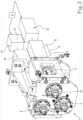
Figure 1 is a schematic front view illustrating a machine for making absorbent sanitary articles according to this invention; -
Figure 2 is a schematic perspective view of a cutting unit of the machine ofFigure 1 . - The
reference numeral 1 denotes a machine for making absorbent sanitary articles according to this invention. - The
machine 1 comprises at least onecutting unit 2 configured to divide a continuous web 3 intosegments 4 intended for manufacturing an absorbent sanitary article. - The
cutting unit 2 comprises ananvil member 5 and acutting member 6 acting in conjunction with theanvil member 5. - The
anvil member 5 comprises adrum 7, rotating about a respective axis ofrotation 7a, for retaining the continuous web 3 and thesegments 4 obtained therefrom. - The
cutting unit 2 comprises a control anddrive unit 8 configured to control the movement of thecutting member 6 at least as a function of the rotation speed of thedrum 7 of theanvil member 5. - The
cutting member 2 comprises afirst cutting roller 9 and asecond cutting roller 10, both acting in conjunction with thedrum 7 of theanvil member 5 and each rotating about a respective axis ofrotation - The
first cutting roller 9 and thesecond cutting roller 10 each compriserespective cutting members 11 driven in rotation about respective axes ofrotation - The control and
drive unit 8 is configured to control the rotation speed of thefirst cutting roller 9 or, alternatively, the rotation speed of thesecond cutting roller 10 in relation to a respective size of an absorbent article to be made. The control anddrive unit 8 is configured to control the rotation speed of thefirst roller 9 as a function of a first size range or, alternatively, to control the rotation speed of thesecond roller 10 as a function of a second size range. Advantageously, the control anddrive unit 8 is configured to control the rotation speed of thefirst cutting roller 9 or, alternatively, the rotation speed of thesecond cutting roller 10 according to the size to be processed. Thus, thefirst cutting roller 9 and thesecond roller 10 can rotate at the maximum speeds permitted by the respective actuators since they are controlled by respective laws of motion corresponding to the sizes associated with thefirst roller 9 and thesecond roller 10. - The control and
drive unit 8 is configured to control the rotation speed of thefirst roller 9 or of thesecond roller 10 according to a law of motion corresponding to a respective size belonging to the first size range or to the second size range; each law of motion has respective accelerations and decelerations. - The control and
drive unit 8 is configured to receive instructions relating to the laws of motion to be applied to thefirst roller 9 and to receive instructions relating to the laws of motion to be applied to thesecond roller 10. - The control and
drive unit 8 is configured to be programmed from the outside and to receive instructions relating to the laws of motion of the actuating means 13, 14. - For example, the instructions may be entered using a control panel installed in the
machine 1. - In a first variant embodiment, the
machine 1 comprises first actuating means 12 for actuating thefirst cutting roller 9 and second actuating means 13 for actuating thesecond cutting roller 10. - Preferably, the
actuators - In a first variant embodiment, the
machine 1 comprises actuating means 14, 13 configured to move thefirst cutting roller 9 or, alternatively, thesecond cutting roller 10. - In this embodiment, if the roller being moved is the
first cutting roller 9 to make the sizes corresponding to the first size range, the actuating means 14 are associated with thefirst cutting roller 9. - If the roller being moved is the
second cutting roller 10 to make the sizes corresponding to the second size range, the actuating means 14 are associated with thesecond cutting roller 10. - The actuating means 13, 14 are configured to set the
first cutting roller 9 in rotation about its axis ofrotation 9a via respective motion transmission means T1 and to set thesecond cutting roller 10 in rotation about its axis ofrotation 10a via respective motion transmission means T2. - The control and drive
unit 8 is configured to selectively command the actuation of thefirst cutting roller 9 and thesecond cutting roller 10 via the actuating means 13, 14 as a function of a first size range and a second size range of absorbent sanitary articles respectively, and to apply to thefirst cutting roller 9 a law of motion corresponding to a respective size belonging to the first size range and to impart to thesecond cutting roller 10 a law of motion corresponding to a respective size belonging to the second size range; each law of motion has respective accelerations and decelerations. Themachine 1 comprises actuating means 15 for actuating thedrum 7 for retaining the continuous web 3 and thesegments 4 obtained therefrom. Preferably, the actuating means mentioned in this disclosure are electric actuators. - This invention also relates to a method for making absorbent sanitary articles, comprising a step of cutting configured to divide a continuous web 3 into
segments 4 intended for manufacturing an absorbent sanitary article. The step of cutting comprises controlling the rotation speed of afirst cutting roller 9 or of asecond cutting roller 10, both acting in conjunction with thesame anvil member 5, as a function of a respective first size range and of a second size range of absorbent sanitary articles. - The step of cutting comprises selectively commanding the rotation of one between a
first cutting roller 9 and asecond cutting roller 10, both acting in conjunction with thesame anvil member 5, as a function of a respective first size range and of a second size range of absorbent sanitary articles, and applying the rotation speed to one between thefirst cutting roller 9 or thesecond cutting roller 10. - In the step of cutting, while one between the
first cutting roller 9 and thesecond cutting roller 10 rotates about a respective axis ofrotation - The step of cutting comprises applying a law of motion to the rotation of the
first cutting roller 9 or of thesecond cutting roller 10 corresponding to a respective size belonging to the first size range or to the second size range, each law of motion having respective accelerations and decelerations.
Claims (5)
- A machine for making absorbent sanitary articles, comprising at least one cutting unit (2) configured to divide a continuous web (3) into segments (4) intended for manufacturing an absorbent sanitary article;the cutting unit (2) comprises an anvil member (5) and a cutting member (6) acting in conjunction with the anvil member (5);the anvil member (5) comprises a drum (7), rotating about a respective axis of rotation (7a), for retaining the continuous web (3) and the segments (4) obtained therefrom;the cutting unit (2) comprises a control and drive unit (8) configured to control the movement of the cutting member (6) at least as a function of the rotation speed of the drum (7) of the anvil member (5);characterized in thatthe cutting member (6) comprises a first cutting roller (9) and a second cutting roller (10), distinct from each other, both acting in conjunction with the drum (7) of the anvil member (5) and each rotating about a respective axis of rotation (9a, 10a);actuating means (13, 14) are configured to set the first cutting roller (9) in rotation about its axis of rotation (9a) via respective motion transmission means (T1) and to set the second cutting roller (10) in rotation about its axis of rotation (10a) via respective motion transmission means (T2);the control and drive unit (8) is configured to selectively command the actuation of the first cutting roller (9) and the second cutting roller (10) via the actuating means (13, 14) as a function of a first size range and a second size range of absorbent sanitary articles respectively, and to impart to the first cutting roller (9) a law of motion corresponding to a respective size belonging to the first size range and to apply to the second cutting roller (10) a law of motion corresponding to a respective size belonging to the second size range; each law of motion has respective accelerations and decelerations.
- The machine according to the preceding claim, wherein the control and drive unit (8) is configured to be programmed from the outside and to receive instructions relating to the laws of motion of the actuating means (13, 14).
- The machine according to any one of the preceding claims, wherein the actuating means (14) are configured to move the first cutting roller (9) or, alternatively, the second cutting roller (10).
- The machine according to any one of the preceding claims, wherein the actuating means (13, 14) comprise first actuating means (14) for actuating the first cutting roller (9) and second actuating means (13) for actuating the second cutting roller (10).
- A method for making absorbent sanitary articles, comprising a step of cutting to divide a continuous web (3) into segments (4) intended for manufacturing an absorbent sanitary article;the step of cutting comprises selectively commanding the rotation of one between a first cutting roller (9) and a second cutting roller (10), both acting in conjunction with the same anvil member (5), as a function of a respective first size range and of a second size range of absorbent sanitary articles, and applying the rotation speed to one between the first cutting roller (9) or the second cutting roller (10);in the step of cutting, while one between the first cutting roller (9) and the second cutting roller (10) rotates about a respective axis of rotation (9a, 10a), the other remains in a paused condition;the step of cutting comprises applying a law of motion to the rotation of the first cutting roller (9) or of the second cutting roller (10) corresponding to a respective size belonging to the first size range or to the second size range, each law of motion having respective accelerations and decelerations.
Applications Claiming Priority (1)
| Application Number | Priority Date | Filing Date | Title |
|---|---|---|---|
| IT102022000016608A IT202200016608A1 (en) | 2022-08-04 | 2022-08-04 | Machine for the production of absorbent sanitary articles |
Publications (2)
| Publication Number | Publication Date |
|---|---|
| EP4316438A1 true EP4316438A1 (en) | 2024-02-07 |
| EP4316438B1 EP4316438B1 (en) | 2025-11-19 |
Family
ID=83899409
Family Applications (1)
| Application Number | Title | Priority Date | Filing Date |
|---|---|---|---|
| EP23189389.2A Active EP4316438B1 (en) | 2022-08-04 | 2023-08-03 | Machine for making absorbent sanitary articles |
Country Status (4)
| Country | Link |
|---|---|
| US (1) | US20240082071A1 (en) |
| EP (1) | EP4316438B1 (en) |
| JP (1) | JP2024022539A (en) |
| IT (1) | IT202200016608A1 (en) |
Citations (1)
| Publication number | Priority date | Publication date | Assignee | Title |
|---|---|---|---|---|
| EP2581068A2 (en) * | 2011-10-14 | 2013-04-17 | Curt G. Joa, Inc. | Methods and apparatus for application of nested zero waste ear to traveling web and formation of articles using a dual cut slip unit |
Family Cites Families (4)
| Publication number | Priority date | Publication date | Assignee | Title |
|---|---|---|---|---|
| US4074599A (en) * | 1976-07-14 | 1978-02-21 | Wood Industries, Inc. | Paper web perforating machine |
| US6544375B1 (en) * | 1998-11-23 | 2003-04-08 | The Procter & Gamble Company | Process for applying discrete web portions to a receiving web |
| DE502006007084D1 (en) * | 2006-03-22 | 2010-07-15 | Hunkeler Ag | Cross-cutting device and method for operating such a cross-cutting device |
| US20100101386A1 (en) * | 2008-10-29 | 2010-04-29 | Goss International Americas, Inc. | Variable signature length web cutting apparatus |
-
2022
- 2022-08-04 IT IT102022000016608A patent/IT202200016608A1/en unknown
-
2023
- 2023-08-02 JP JP2023126224A patent/JP2024022539A/en active Pending
- 2023-08-02 US US18/364,115 patent/US20240082071A1/en active Pending
- 2023-08-03 EP EP23189389.2A patent/EP4316438B1/en active Active
Patent Citations (1)
| Publication number | Priority date | Publication date | Assignee | Title |
|---|---|---|---|---|
| EP2581068A2 (en) * | 2011-10-14 | 2013-04-17 | Curt G. Joa, Inc. | Methods and apparatus for application of nested zero waste ear to traveling web and formation of articles using a dual cut slip unit |
Also Published As
| Publication number | Publication date |
|---|---|
| EP4316438B1 (en) | 2025-11-19 |
| US20240082071A1 (en) | 2024-03-14 |
| JP2024022539A (en) | 2024-02-16 |
| IT202200016608A1 (en) | 2024-02-04 |
Similar Documents
| Publication | Publication Date | Title |
|---|---|---|
| EP0885095B1 (en) | On demand cross web perforation | |
| EP1031401B1 (en) | Apparatus for the transverse cutting of weblike material | |
| US5079876A (en) | Method and installation for processing glass plates | |
| US20130036884A1 (en) | Method and apparatus for punching or perforating moving material webs | |
| US9914234B2 (en) | Multilateral cutter | |
| EP3424334B1 (en) | Provision of web-shaped sheet material to a cutting area | |
| JPH0647905A (en) | Rotary printing machine | |
| US3742798A (en) | Corrugated sheet cutoff length adjustment apparatus | |
| DK2624990T3 (en) | Mode for cutting block materials and cutting machine for cutting block materials | |
| EP4316438B1 (en) | Machine for making absorbent sanitary articles | |
| WO2008059270A2 (en) | Apparatus for cutting and/or shearing fibre | |
| CA2028624C (en) | Apparatus and method for the in-line cropping and/or chamfering of a plastic tube | |
| JP2025514931A (en) | Apparatus and method for forming cell stacks for the energy cell manufacturing industry - Patents.com | |
| CN100340392C (en) | Cross cutting machine capable of moving with the cut article in same speed and direction | |
| JPS6384868A (en) | Device for driving and controlling wire in wire saw | |
| US20110219924A1 (en) | Method for Efficient Order Change of a Corrugator Dry End Using Order Look Ahead | |
| US4047468A (en) | Strand milling method | |
| CN219634665U (en) | Paper bag forming machine | |
| DE102005049401A1 (en) | Longitudinal folder, method for operating the longitudinal folder and method for synchronizing the Längsfalzapparates | |
| US5217724A (en) | Apparatus for the in-line cropping and/or chamfering of a plastic tube | |
| EP4566577B1 (en) | An apparatus for treating continuous moving webs and a machine comprising this apparatus | |
| DE69905087T2 (en) | Multiple twisting machine with single spindle drive | |
| EP1412144A1 (en) | Method and device for adjusting the degree of engagement of a tool with a web of material running past it | |
| JP4822896B2 (en) | Composite sheet manufacturing method and apparatus | |
| WO2001053156A1 (en) | Application of adhesive-backed elements to moving web or articles |
Legal Events
| Date | Code | Title | Description |
|---|---|---|---|
| PUAI | Public reference made under article 153(3) epc to a published international application that has entered the european phase |
Free format text: ORIGINAL CODE: 0009012 |
|
| STAA | Information on the status of an ep patent application or granted ep patent |
Free format text: STATUS: THE APPLICATION HAS BEEN PUBLISHED |
|
| AK | Designated contracting states |
Kind code of ref document: A1 Designated state(s): AL AT BE BG CH CY CZ DE DK EE ES FI FR GB GR HR HU IE IS IT LI LT LU LV MC ME MK MT NL NO PL PT RO RS SE SI SK SM TR |
|
| STAA | Information on the status of an ep patent application or granted ep patent |
Free format text: STATUS: REQUEST FOR EXAMINATION WAS MADE |
|
| 17P | Request for examination filed |
Effective date: 20240801 |
|
| RBV | Designated contracting states (corrected) |
Designated state(s): AL AT BE BG CH CY CZ DE DK EE ES FI FR GB GR HR HU IE IS IT LI LT LU LV MC ME MK MT NL NO PL PT RO RS SE SI SK SM TR |
|
| GRAP | Despatch of communication of intention to grant a patent |
Free format text: ORIGINAL CODE: EPIDOSNIGR1 |
|
| STAA | Information on the status of an ep patent application or granted ep patent |
Free format text: STATUS: GRANT OF PATENT IS INTENDED |
|
| INTG | Intention to grant announced |
Effective date: 20250618 |
|
| GRAS | Grant fee paid |
Free format text: ORIGINAL CODE: EPIDOSNIGR3 |
|
| GRAA | (expected) grant |
Free format text: ORIGINAL CODE: 0009210 |
|
| STAA | Information on the status of an ep patent application or granted ep patent |
Free format text: STATUS: THE PATENT HAS BEEN GRANTED |
|
| AK | Designated contracting states |
Kind code of ref document: B1 Designated state(s): AL AT BE BG CH CY CZ DE DK EE ES FI FR GB GR HR HU IE IS IT LI LT LU LV MC ME MK MT NL NO PL PT RO RS SE SI SK SM TR |
|
| REG | Reference to a national code |
Ref country code: CH Ref legal event code: F10 Free format text: ST27 STATUS EVENT CODE: U-0-0-F10-F00 (AS PROVIDED BY THE NATIONAL OFFICE) Effective date: 20251119 Ref country code: GB Ref legal event code: FG4D |
|
| REG | Reference to a national code |
Ref country code: DE Ref legal event code: R096 Ref document number: 602023008711 Country of ref document: DE |
|
| REG | Reference to a national code |
Ref country code: IE Ref legal event code: FG4D |
|
| REG | Reference to a national code |
Ref country code: NL Ref legal event code: MP Effective date: 20251119 |
|
| PG25 | Lapsed in a contracting state [announced via postgrant information from national office to epo] |
Ref country code: ES Free format text: LAPSE BECAUSE OF FAILURE TO SUBMIT A TRANSLATION OF THE DESCRIPTION OR TO PAY THE FEE WITHIN THE PRESCRIBED TIME-LIMIT Effective date: 20251119 |
|
| REG | Reference to a national code |
Ref country code: LT Ref legal event code: MG9D |
|
| PG25 | Lapsed in a contracting state [announced via postgrant information from national office to epo] |
Ref country code: NO Free format text: LAPSE BECAUSE OF FAILURE TO SUBMIT A TRANSLATION OF THE DESCRIPTION OR TO PAY THE FEE WITHIN THE PRESCRIBED TIME-LIMIT Effective date: 20260219 |
|
| PG25 | Lapsed in a contracting state [announced via postgrant information from national office to epo] |
Ref country code: AT Free format text: LAPSE BECAUSE OF FAILURE TO SUBMIT A TRANSLATION OF THE DESCRIPTION OR TO PAY THE FEE WITHIN THE PRESCRIBED TIME-LIMIT Effective date: 20251119 Ref country code: FI Free format text: LAPSE BECAUSE OF FAILURE TO SUBMIT A TRANSLATION OF THE DESCRIPTION OR TO PAY THE FEE WITHIN THE PRESCRIBED TIME-LIMIT Effective date: 20251119 Ref country code: HR Free format text: LAPSE BECAUSE OF FAILURE TO SUBMIT A TRANSLATION OF THE DESCRIPTION OR TO PAY THE FEE WITHIN THE PRESCRIBED TIME-LIMIT Effective date: 20251119 |
|
| REG | Reference to a national code |
Ref country code: AT Ref legal event code: MK05 Ref document number: 1858207 Country of ref document: AT Kind code of ref document: T Effective date: 20251119 |
|
| PG25 | Lapsed in a contracting state [announced via postgrant information from national office to epo] |
Ref country code: NL Free format text: LAPSE BECAUSE OF FAILURE TO SUBMIT A TRANSLATION OF THE DESCRIPTION OR TO PAY THE FEE WITHIN THE PRESCRIBED TIME-LIMIT Effective date: 20251119 |
|
| PG25 | Lapsed in a contracting state [announced via postgrant information from national office to epo] |
Ref country code: RS Free format text: LAPSE BECAUSE OF FAILURE TO SUBMIT A TRANSLATION OF THE DESCRIPTION OR TO PAY THE FEE WITHIN THE PRESCRIBED TIME-LIMIT Effective date: 20260219 |
|
| PG25 | Lapsed in a contracting state [announced via postgrant information from national office to epo] |
Ref country code: IS Free format text: LAPSE BECAUSE OF FAILURE TO SUBMIT A TRANSLATION OF THE DESCRIPTION OR TO PAY THE FEE WITHIN THE PRESCRIBED TIME-LIMIT Effective date: 20260319 |
|
| PG25 | Lapsed in a contracting state [announced via postgrant information from national office to epo] |
Ref country code: PT Free format text: LAPSE BECAUSE OF FAILURE TO SUBMIT A TRANSLATION OF THE DESCRIPTION OR TO PAY THE FEE WITHIN THE PRESCRIBED TIME-LIMIT Effective date: 20260319 |
|
| PG25 | Lapsed in a contracting state [announced via postgrant information from national office to epo] |
Ref country code: PL Free format text: LAPSE BECAUSE OF FAILURE TO SUBMIT A TRANSLATION OF THE DESCRIPTION OR TO PAY THE FEE WITHIN THE PRESCRIBED TIME-LIMIT Effective date: 20251119 |
|
| PG25 | Lapsed in a contracting state [announced via postgrant information from national office to epo] |
Ref country code: LV Free format text: LAPSE BECAUSE OF FAILURE TO SUBMIT A TRANSLATION OF THE DESCRIPTION OR TO PAY THE FEE WITHIN THE PRESCRIBED TIME-LIMIT Effective date: 20251119 |