EP4313838B1 - Offshore crane vessel and method for operating the offshore crane vessel - Google Patents
Offshore crane vessel and method for operating the offshore crane vessel Download PDFInfo
- Publication number
- EP4313838B1 EP4313838B1 EP22717080.0A EP22717080A EP4313838B1 EP 4313838 B1 EP4313838 B1 EP 4313838B1 EP 22717080 A EP22717080 A EP 22717080A EP 4313838 B1 EP4313838 B1 EP 4313838B1
- Authority
- EP
- European Patent Office
- Prior art keywords
- boom
- head structure
- travelling head
- luffing
- tip end
- Prior art date
- Legal status (The legal status is an assumption and is not a legal conclusion. Google has not performed a legal analysis and makes no representation as to the accuracy of the status listed.)
- Active
Links
Images


Classifications
-
- B—PERFORMING OPERATIONS; TRANSPORTING
- B66—HOISTING; LIFTING; HAULING
- B66C—CRANES; LOAD-ENGAGING ELEMENTS OR DEVICES FOR CRANES, CAPSTANS, WINCHES, OR TACKLES
- B66C23/00—Cranes comprising essentially a beam, boom, or triangular structure acting as a cantilever and mounted for translatory of swinging movements in vertical or horizontal planes or a combination of such movements, e.g. jib-cranes, derricks, tower cranes
- B66C23/18—Cranes comprising essentially a beam, boom, or triangular structure acting as a cantilever and mounted for translatory of swinging movements in vertical or horizontal planes or a combination of such movements, e.g. jib-cranes, derricks, tower cranes specially adapted for use in particular purposes
- B66C23/36—Cranes comprising essentially a beam, boom, or triangular structure acting as a cantilever and mounted for translatory of swinging movements in vertical or horizontal planes or a combination of such movements, e.g. jib-cranes, derricks, tower cranes specially adapted for use in particular purposes mounted on road or rail vehicles; Manually-movable jib-cranes for use in workshops; Floating cranes
- B66C23/52—Floating cranes
-
- B—PERFORMING OPERATIONS; TRANSPORTING
- B66—HOISTING; LIFTING; HAULING
- B66C—CRANES; LOAD-ENGAGING ELEMENTS OR DEVICES FOR CRANES, CAPSTANS, WINCHES, OR TACKLES
- B66C23/00—Cranes comprising essentially a beam, boom, or triangular structure acting as a cantilever and mounted for translatory of swinging movements in vertical or horizontal planes or a combination of such movements, e.g. jib-cranes, derricks, tower cranes
- B66C23/62—Constructional features or details
- B66C23/64—Jibs
- B66C23/66—Outer or upper end constructions
-
- B—PERFORMING OPERATIONS; TRANSPORTING
- B66—HOISTING; LIFTING; HAULING
- B66C—CRANES; LOAD-ENGAGING ELEMENTS OR DEVICES FOR CRANES, CAPSTANS, WINCHES, OR TACKLES
- B66C23/00—Cranes comprising essentially a beam, boom, or triangular structure acting as a cantilever and mounted for translatory of swinging movements in vertical or horizontal planes or a combination of such movements, e.g. jib-cranes, derricks, tower cranes
- B66C23/62—Constructional features or details
- B66C23/82—Luffing gear
-
- B—PERFORMING OPERATIONS; TRANSPORTING
- B66—HOISTING; LIFTING; HAULING
- B66C—CRANES; LOAD-ENGAGING ELEMENTS OR DEVICES FOR CRANES, CAPSTANS, WINCHES, OR TACKLES
- B66C23/00—Cranes comprising essentially a beam, boom, or triangular structure acting as a cantilever and mounted for translatory of swinging movements in vertical or horizontal planes or a combination of such movements, e.g. jib-cranes, derricks, tower cranes
- B66C23/18—Cranes comprising essentially a beam, boom, or triangular structure acting as a cantilever and mounted for translatory of swinging movements in vertical or horizontal planes or a combination of such movements, e.g. jib-cranes, derricks, tower cranes specially adapted for use in particular purposes
- B66C23/185—Cranes comprising essentially a beam, boom, or triangular structure acting as a cantilever and mounted for translatory of swinging movements in vertical or horizontal planes or a combination of such movements, e.g. jib-cranes, derricks, tower cranes specially adapted for use in particular purposes for use erecting wind turbines
Definitions
- the invention relates to the field of offshore crane vessels with cranes, for example for use in the handling of one or more offshore wind turbine components, e.g. for installation and/or maintenance of an offshore wind turbine.
- the offshore wind turbine is installed or serviced using a jack-up vessel that is positioned close to the wind turbine location and then the jack-up legs are extended and the vessel is lifted, at least in part but mostly entirely above the sea, to provide a stabilized situation for the crane operation.
- the invention is primarily envisaged for the field of offshore wind turbines, so for maintenance, and also for installation and/or decommission of wind turbines.
- the inventive crane may also be of use in other offshore applications, like oil & gas related operations, civil engineering operations, etc.
- offshore crane vessels comprising a hull, a deck and a crane, the crane comprising:
- a tall crane that is, the crane will have a long boom so as to have a long reach.
- a long boom has a length of at least 60 meters, e.g. between 80 and 200 meters. Such a boom protrudes outside a perimeter of the deck of the vessel when the boom is in a horizontally orientation, e.g. in a boom storage position, e.g. during transit.
- the volume and weight of the protruding boom and main hoist block assembly has several disadvantages.
- a known solution is to provide a telescopic boom as disclosed in WO 2020/244973 of same applicant.
- Another document that discloses an offshore crane with the features of the preamble of claim 1 is known from WO 2020/209712 A .
- the offshore crane vessel is characterised in that the head structure is a travelling head structure which is slidable along a part of the boom from the tip end to a second position on the boom and wherein in the horizontal rest position of the boom and in the second position of the travelling head structure the main hoist block assembly is positioned above the deck of the vessel.
- An advantage of the retracted travelling head structure in the second position is that the weight of the travelling head structure and main hoist block assembly is provided above deck, preferably in the vicinity of the boom rest. This prevents fatigue and/or boom bending, in particular during sailing.
- the retractability allows to select an advantageous distribution of weight on the vessel, by selecting a desired position of the of centre of gravity of main block.
- Another advantage of the sliding of the weight is that oscillation of the boom during sailing can be prevented, as the natural frequency of the boom can be tuned.
- main block hoist assembly at the second position, above deck is the accessibility of the travelling head structure and main block hoist assembly for inspection, maintenance and greasing.
- Yet another advantage of the retraction of the travelling head structure and main block hoist assembly is that there is more clearance to the waves during sailing.
- the boom in the horizontal rest position is usually positioned 20-35 meters above sea level. By removing the volume of the travelling head structure and the main hoist block assembly and possibly a main load suspension device suspended therefrom, this 25-35 meters between sea level and the boom is free space, providing a clearance for waves.
- Yet another advantage of the retraction of the travelling head structure and main block hoist assembly is that there is more clearance in harbours.
- the boom in the horizontal rest position is usually positioned 20-35 meters above sea level, which is commonly no problem above a cay.
- the volume of the main hoist block assembly closer to the waterline is often problematic.
- the offshore crane vessel of the invention is brought to a rest position having the above-indicated advantages.
- Such a method comprises the steps of:
- the main hoist block assembly in this rest position is supported in a main hoist block assembly support.
- the travelling head structure is also fixed to the boom at the second position.
- the slidable travelling head structure, and a boom allowing the sliding of the travelling head structure therealong can be of a relatively simple construction.
- the boom needs to be strong enough to support the travelling head structure and allow the sliding thereof. Hence, a reinforced structure may be desired.
- the boom does not need to be hollow as e.g. required for telescopic boom sections. It is envisaged that cords of the boom function as rails for the travelling head structure. In particular when the sliding takes place in a horizontal position of the boom there additional forces on the boom during sliding are limited and do not require major modifications of the boom structure.
- the offshore crane vessel of the invention can be a monohull or multihull vessel, a jack-up vessel or even a barge. It comprises a hull with a deck.
- a pedestal of the crane is mounted to, or formed integral with the hull of the vessel.
- the pedestal is formed around a leg of the jack-up vessel to form a so-called 'around the leg crane'.
- a superstructure is rotationally supported by the pedestal for rotation of the superstructure relative to the pedestal about a vertical slew axis.
- the superstructure comprises a boom connection member.
- a crane boom having a longitudinal axis and a length of 60-200 meters between a pivot end and a tip end.
- the pivot end is connected to the boom connection member on the superstructure so that the boom is pivotable up and down about a horizontal boom pivot axis.
- the length of the boom is such that in a horizontal rest position the tip end protrudes outside a perimeter of the hull of the vessel. Possibly, the boom extends significantly outside the perimeter, e.g. more than 5 meters, e.g. more than 10 meters.
- the vessel is provided with a boom rest to support the boom in a horizontal rest position, e.g. when the crane is not in use, such as during transit and in harbours.
- the horizontal rest position is essentially horizontal, and may in practical embodiments deviate 1-15 degrees.
- the type of crane of the invention comprises a boom luffing assembly for pivoting the boom about the horizontal boom pivot axis.
- the boom luffing assembly comprises a boom luffing winch and an elongated luffing member extending to the tip end of the boom.
- the elongated luffing member comprises a luffing cable extending from the winch and preferably via a luffing cable guide provided at the superstructure.
- a main hoisting device for hoisting a load.
- the main hoisting device comprises a main hoisting winch, at least one associated main hoisting cable, a main hoist block assembly supported by a head structure.
- the main hoisting cable extends from the main hoisting winch to the main hoist block assembly.
- the main hoist block assembly comprises a number of sheaves for the hoisting cable.
- a main load suspension device is preferably suspended from the main block hoist assembly.
- the head structure is a travelling head structure which is slidable along a part of the boom from the tip end to a second position on the boom. In the horizontal rest position of the boom and in the second position of the travelling head structure the main hoist block assembly is positioned above the deck of the vessel.
- the travelling head structure is e.g. embodied such that it encompasses the boom entirely, as a box. It is also conceivable that the travelling head structure has an U-shape, extending over the bottom part and (part of) the sides of the boom.
- a main hoist block assembly support is provided on the deck of the vessel, adapted to support the weight of the main hoist block assembly and possibly also the weight of the travelling head structure.
- the main hoist block assembly support is provided in line with the pedestal and the boom rest. It is also conceivable that the main hoist block assembly support is formed integral with the boom rest. In the horizontal rest position of the boom and in the second position of the main hoist block assembly the main hoist block assembly is aligned with the main hoist block assembly support. The alignment allows the main hoist block assembly support to, in the rest position of the boom, support the weight of the travelling head structure, and possibly that of the main hoist block assembly.
- the main hoist block assembly support allows and simplifies installation and maintenance of the main hoist block assembly, and possibly also alterations of the block and/ or cable configuration in the main hoist block assembly.
- a head drive is provided to slide the travelling head structure along the boom.
- a head drive e.g. comprising a head winch and a head cable extending between the head winch and the travelling head structure.
- a drive system is e.g. known as a tugger winch and tugger cable.
- Alternative system e.g. hydraulic systems or comprising a rack and pinion construction are also conceivable.
- the travelling head structure is detachably fixable to the boom at the tip end of the boom and preferably also at the second position of the travelling head structure. This allows the travelling head structure to be fixed to the boom at the tip end thereof during hoisting operations, and detached to allow sliding thereof. Possibly a fastening mechanism is applied that can travel with the travelling head structure to the second position, to fix the travelling head structure to the boom at the second position.
- a jib with an auxiliary hoist block is connected to the travelling head structure and slidable with the travelling head structure along the boom.
- Such an auxiliary hoist block is often present, and thus also protrudes outside the perimeter of the hull of the vessel.
- the retraction of this jib and auxiliary hoist block, together with thee head structure, to a proximal position attributes to the above-indicated advantages of the invention, including an increased clearance and improved weight distribution. It is envisaged that the jib is configured as disclosed in WO2020225157 .
- the main hoist block assembly is pivotably supported by the travelling head structure about a horizontal pivot structure. This may be advantageous during hoisting operations. In addition, this may be advantageous when the main hoist block assembly in the second position of the travelling head structure. When pivoted to a horizontal position the distance to the deck may be increased in embodiments, thereby attributing to a clear deck space.
- the second position on the boom is at a distance from the pivot end of 50-90% of the length of the boom. Most important is that in the second position of the travelling head structure the main hoist block assembly is positioned above the deck of the vessel. However, further weight-related advantages are achieved when the second position more remote from the pivot end. As elucidated later on, further advantages relating to the luffing of the boom are also conceivable, wherein the second position is more proximal than necessary to be above deck.
- the boom is embodied as a hollow box structure, preferably a latticed hollow box structure.
- a possible advantageous configuration of the same applicant is disclosed in WO 2018/208158 .
- a known alternative is a A-frame booms which has generally the shape of an A with two boom legs connected, each embodied as a latticed hollow box structure.
- Another known example, is a twin leg boom with two parallel legs, each embodied as a latticed hollow box structure, wherein the legs are interconnected by multiple cross members, distributed over the length thereof, interconnecting the boom legs.
- a boom portion between the second position of the travelling head structure and the tip end is detachable and can preferably be parked on deck of the vessel. Preferably this is an end portion of the boom. When detaching this end portion from the boom, it is possible that in the horizontal rest position the boom no longer protrudes outside the perimeter of the hull of the vessel.
- a boom luffing assembly for pivoting the boom about the horizontal boom pivot axis.
- the boom luffing assembly comprises a boom winch and an elongated luffing member extending to the boom.
- the boom luffing assembly advantageously also comprises a luffing cable extending from the boom luffing winch.
- the elongated luffing member can also engage the boom at a second luffing position opposite the main hoist block assembly at the second position of the travelling head structure. This allows a transfer of the load of the travelling head structure with the main hoist block assembly to the boom luffing assembly.
- Such a configuration with the luffing member opposite the travelling head structure is advantageous for luffing the boom out of its essentially horizontal rest position.
- luffing causes high bucking loads on the boom.
- the boom is reinforced at this location to allow a transfer of the load of the travelling head structure with the main hoist block assembly to the boom luffing assembly.
- the elongated luffing member is connected to the travelling head structure, and is slidable with the travelling head structure along the boom.
- the travelling head structure may allow for the transfer of loads.
- the elongated luffing member comprises an end part fixed to the tip end of the boom, and an auxiliary structure attachable to the boom at a second luffing position opposite the main hoist block assembly at the second position of the travelling head structure.
- an end part of the elongated luffing member is detachable from the boom, and can be attached to the boom at the tip end and at a second luffing position opposite the main hoist block assembly at the second position of the travelling head structure.
- this end part is slidable along the boom.
- travelling head structure enables inventive methods of operation of such an offshore crane vessel.
- the crane can subsequently be brought to an alternative operational position, wherein the method further comprises the steps of:
- Such an operation a.o. involves the pivoting of the boom by the boom luffing assembly away from the horizontal rest position.
- the crane is brought to an alternative operational position, wherein the method comprises the steps of:
- This alternative operational position is in particular advantageous for very long booms, wherein luffing with the elongated luffing member extending to the tip end of the boom is difficult.
- the elongated luffing member in the second position of the travelling head structure has slided with the travelling head structure to a position closer to the pivot end of the boom.
- the elongated luffing member comprises an auxiliary structure attachable to the boom at a second luffing position opposite the second position of the travelling head structure. In both situations, the elongated luffing member engages at a position closer to the pivot end of the boom, which is highly advantageous for upending an elongated boom.
- the method comprises the following steps:
- the luffing member travels to the tip end with the travelling head structure.
- the auxiliary structure of the elongated luffing member is detached from the boom at the second luffing position.
- the crane is brought to an alternative operational position with the boom at an upward pivoted, non-horizontal position of the boom, possibly wherein the boom is supported by a boom stop.
- the steps of detaching and sliding the travelling head structure are carried out with the boom out of the rest position.
- a second aspect of the disclosure which is not part of the claimed matter relates to a crane, preferably a crane on an offshore crane vessel, comprising:
- a disadvantage of very long booms with a heavy travelling head structure and main hoist block assembly at a tip end thereof is that luffing causes high bucking loads on the boom. In particular when luffing a boom out of its essentially horizontal rest position this is disadvantageous.
- the head structure is a travelling head structure which is slidable along a part of the boom from the tip end to a second position on the boom, and in that the elongated luffing member can engage the boom at a tip end and at a second luffing position opposite the main hoist block assembly at the second position of the travelling head structure.
- the boom is reinforced at this location to allow a transfer of the load of the travelling head structure with the main hoist block assembly to the boom luffing assembly.
- the elongated luffing member is connected to the travelling head structure, and is slidable with the travelling head structure along the boom.
- the travelling head structure may allow for the transfer of loads.
- the elongated luffing member comprises an end part fixed to the tip end of the boom, and an auxiliary structure attachable to the boom at a second luffing position opposite the main hoist block assembly at the second position of the travelling head structure.
- an end part of the elongated luffing member is detachable from the boom, and can be attached to the boom at the tip end and at a second luffing position opposite the main hoist block assembly at the second position of the travelling head structure.
- this end part is slidable along the boom.
- the disclosure also relates to a method wherein the crane is brought to an alternative operational position, wherein the method comprises the steps of:
- This alternative operational position is in particular advantageous for very long booms, wherein luffing with the elongated luffing member extending to the tip end of the boom is difficult.
- the elongated luffing member in the second position of the travelling head structure has slided with the travelling head structure to a proximal position closer to the pivot end of the boom.
- the elongated luffing member comprises an auxiliary structure attachable to the boom at a second luffing position opposite the second position of the travelling head structure. In both situations, the elongated luffing member engages at a position closer to the pivot end of the boom, which is highly advantageous for upending an elongated boom.
- the method comprises the following steps:
- the luffing member travels to the tip end with the travelling head structure.
- the auxiliary structure of the elongated luffing member is detached from the boom at the second luffing position.
- the crane is brought to an alternative operational position with the boom at an upward pivoted, non-horizontal position of the boom, possibly wherein the boom is supported by a boom stop.
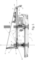
- an offshore crane vessel 1 comprising a hull 2, a deck 3 and a crane 10.
- the crane 10 comprises a pedestal 11 mounted to, or formed integral with, the hull 2 of the vessel 1.
- the crane further comprises
- the boom 50 of Fig. 1 protrudes outside the perimeter of the hull 2 of the vessel 1 in the rest position of the boom.
- the main hoist block assembly 75 is in Fig. 1 positioned at the tip end 51 of the boom 50. As a result, the main hoist block assembly 75 protrudes outside the perimeter of the hull 2 of the vessel 1 in the rest position of the boom 50.
- the volume and weight of the protruding boom and main hoist block assembly has several disadvantages.
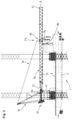
- the head structure 60 shown in Figs. 1 and 2 is a travelling head structure 60 which is slidable along a part of the boom 50 from the tip end 51 to a second position P2 on the boom 50.
- the head structure 60 can translate from the position shown in Fig. 1 , where it is located at the tip end 51, to the position P2 as shown in Fig. 2 .
- the boom 50 is also in the horizontal rest position of the boom 50, and in the second position P2 of the travelling head structure 60 the main hoist block assembly 75 is positioned above the deck 3 of the vessel 1.
- a main hoist block assembly 75 hangs freely from the head structure 60, and is thus supported thereby.
- a main hoist block assembly support is provided on the deck of the vessel in line with the pedestal and the boom rest; and wherein in the horizontal rest position of the boom and in the second position of the hoist block assembly the hoist block assembly is aligned with the main hoist block assembly support, such that in the rest position of the boom the weight of the travelling head structure and the main hoist block assembly is supported by the main hoist block assembly support.
- the position of the boom 50 in Fig. 1 is in the above called a horizontal rest position, that may e.g. be used during transit. It should be appreciated that the rest position may equally deviate from the horizontal, e.g. with the boom pointing upwards, so long as the boom 50 is supported by the boom rest 80.
- the boom rest 80 in Fig. 1 it is noted that it to be located on an outer side of the deck 3 as shown in Fig.1 , or that the location may e.g. be further inboard.
- the boom 50 is shown to be embodied as a latticed hollow box structure. It is noted that this is not essential to the invention.
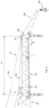
- Fig. 3 is shown the vessel 1 of Fig. 2 with the boom 50 in an upwardly pivoted position and the head structure 60 at a tip end 52 of the boom 50.
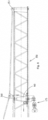
- Fig. 4 is shown the vessel 1 of Fig. 2 with the boom 50 in an upwardly pivoted position and the head structure in an inward position. That is, the head structure 60 in Fig. 4 is closer to the pivot end 52 of the boom 50 than the head structure 60 of Fig. 3 .
- the crane 10 is brought to an alternative operational position. This can e.g. be done from the position as shown in Fig. 3 to the position as shown in Fig. 4 .
- This method comprises the steps of:
- the steps mentioned above are carried out with the boom at an upward pivoted, non-horizontal position of the boom as shown in Figs. 3 and 4 .
- the boom 50 is supported by a boom stop.
- the luffing device is connected to the travelling head structure 60 and as such the luffing member 40 travels with the travelling head structure 60. That is, the luffing device is slidable with the travelling head structure 60 along the boom 50. As a result the luffing device adjusts the elongated luffing member 40 accordingly for the second position P2 of Fig. 4 .
- the luffing device can be connected to a second luffing position on the boom 50.
- Figs. 5A-5C show steps for a method of operating the offshore crane vessel of Fig. 2 .
- the crane is brought to a parking position, the method may comprise the steps of:
- the crane can be brought to an alternative operational position. Then the method described above may further comprise the steps of
- Fig. 6 shows a travelling head structure 160 being slidable along a part of a boom 150 for an offshore crane vessel according to the invention.
- the boom 150 is a gooseneck boom having a cross-section tapering towards the tip end 151. However, the boom may equally have constant cross-section.
- a jib 200 supporting an auxiliary hoist block 220 is connected to the boom 150.
- the boom 150 is provided with rails 210 along which the travelling head structure 160 can slide with a sliding movement S1 as also indicated by the intermediate position P1 of the head structure 160 and the second position P2.
- To reach P2 the head structure 160 has travelled a distance d1 along a slidable portion of the boom 150. This slidable portion allows for translation of the head structure along the boom.
- a head drive can be provided to effect this sliding movement S1, so as to slide the travelling head structure 160 along the boom 150.
- elongated luffing member 140 can be mounted to a strut 230.
- the head structure 160 of Fig. 6 is shown in more detail in Fig. 7 .
- the head structure 160 comprises sliding members 161, e.g. skid shoes, which can slide along the rail 210.
- the head structure as shown in Fig. 7 further comprises a sheave 240.
- a boom 350 for an offshore crane vessel with a head structure 160 located at a tip end 351 of the boom 350.
- the boom 350 is further provided with a provision 360 at second position P2, e.g. for detachably fixating the head structure 160 to provision 360.
- the detachable fixation may e.g. be achieved using attachment devices 165, e.g. cylindrical locking pins, that engage the provision 360.
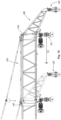
- Fig. 9 shows the boom 350 with the head structure 160 in the second position P2, and with the main hoist block assembly 175 being pivoted upward with respect to a hanging position as shown in Fig. 8 . That is, the main hoist block assembly 175 is pivotably supported by the travelling head structure 160 about a horizontal pivot structure. In Fig. 9 the main hoist block assembly 175 is pivoted to a horizontal position.
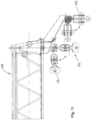
- the main hoist block assembly being pivotably supported as described for Fig. 9 is also shown in Figs. 10 and 11 .
- a boom 450 for an offshore crane vessel with a pivotable main hoist block assembly 175, and with a jib 400 supporting a fixed auxiliary hoist block 420, which jib 400 is connected to a travelling head structure 460. That is, the jib 400 with the auxiliary hoist block 420 is connected to the travelling head structure 460 and slidable therewith along the boom 450, e.g. with the sliding movement S2 shown in Fig. 10 .
- auxiliary hoist block can also be pivotable, this is shown in Fig. 11 for auxiliary hoist block 475.
- Fig. 12 details are shown for a main hoist block assembly for an offshore crane vessel according to the invention.
Landscapes
- Engineering & Computer Science (AREA)
- Mechanical Engineering (AREA)
- Jib Cranes (AREA)
- Carriers, Traveling Bodies, And Overhead Traveling Cranes (AREA)
Priority Applications (1)
| Application Number | Priority Date | Filing Date | Title |
|---|---|---|---|
| EP25166730.9A EP4553030A3 (en) | 2021-03-25 | 2022-03-18 | Crane and method for operating the crane |
Applications Claiming Priority (2)
| Application Number | Priority Date | Filing Date | Title |
|---|---|---|---|
| NL2027839A NL2027839B1 (en) | 2021-03-25 | 2021-03-25 | Offshore crane vessel and method for operating the offshore crane vessel |
| PCT/EP2022/057219 WO2022200230A1 (en) | 2021-03-25 | 2022-03-18 | Offshore crane vessel and method for operating the offshore crane vessel |
Related Child Applications (2)
| Application Number | Title | Priority Date | Filing Date |
|---|---|---|---|
| EP25166730.9A Division EP4553030A3 (en) | 2021-03-25 | 2022-03-18 | Crane and method for operating the crane |
| EP25166730.9A Division-Into EP4553030A3 (en) | 2021-03-25 | 2022-03-18 | Crane and method for operating the crane |
Publications (2)
| Publication Number | Publication Date |
|---|---|
| EP4313838A1 EP4313838A1 (en) | 2024-02-07 |
| EP4313838B1 true EP4313838B1 (en) | 2025-05-21 |
Family
ID=76601653
Family Applications (2)
| Application Number | Title | Priority Date | Filing Date |
|---|---|---|---|
| EP25166730.9A Pending EP4553030A3 (en) | 2021-03-25 | 2022-03-18 | Crane and method for operating the crane |
| EP22717080.0A Active EP4313838B1 (en) | 2021-03-25 | 2022-03-18 | Offshore crane vessel and method for operating the offshore crane vessel |
Family Applications Before (1)
| Application Number | Title | Priority Date | Filing Date |
|---|---|---|---|
| EP25166730.9A Pending EP4553030A3 (en) | 2021-03-25 | 2022-03-18 | Crane and method for operating the crane |
Country Status (6)
| Country | Link |
|---|---|
| US (1) | US20240166477A1 (enExample) |
| EP (2) | EP4553030A3 (enExample) |
| JP (1) | JP2024510818A (enExample) |
| CN (1) | CN117337265A (enExample) |
| NL (1) | NL2027839B1 (enExample) |
| WO (1) | WO2022200230A1 (enExample) |
Families Citing this family (4)
| Publication number | Priority date | Publication date | Assignee | Title |
|---|---|---|---|---|
| NL2033206B1 (en) * | 2022-09-30 | 2024-04-08 | Gustomsc B V | Method for decoupling a crane block from an offshore crane |
| DE102023136579A1 (de) | 2023-12-22 | 2025-06-26 | Liebherr-MCCtec Rostock GmbH | Kran mit aktiver Rückfallstütze |
| CN119269070B (zh) * | 2024-12-10 | 2025-03-11 | 招商局金陵船舶(威海)有限公司 | 一种船舶艉跳板性能测试浮动试验方法 |
| CN120191855B (zh) * | 2025-05-26 | 2025-10-03 | 贵州庞源机械工程有限公司 | 平头式塔机起重臂自卸装置及方法 |
Family Cites Families (12)
| Publication number | Priority date | Publication date | Assignee | Title |
|---|---|---|---|---|
| DE602008003297D1 (de) * | 2008-02-07 | 2010-12-16 | Itrec Bv | Kranfahrzeug |
| NL2004987C2 (nl) * | 2010-06-28 | 2011-12-29 | Ihc Holland Ie Bv | Liftinrichting en werkwijze voor het positioneren van een log object. |
| DE102011015881A1 (de) * | 2011-04-04 | 2012-10-04 | Werner Möbius Engineering GmbH | Kran |
| KR102151476B1 (ko) * | 2012-12-20 | 2020-09-04 | 하이 윈드 엔.브이. | 구조물의 요소를 배치하기 위한 장치 및 방법 |
| SG11201506436RA (en) * | 2013-02-18 | 2015-09-29 | High Wind N V | Device and method for placing a rotor blade of a wind turbine |
| US10906785B2 (en) * | 2016-06-15 | 2021-02-02 | Itrec B.V. | Crane for wind turbine blade assembly, a vessel, a hoisting method, and an assembly method |
| EP3515851B1 (en) * | 2016-09-19 | 2023-06-07 | GustoMSC B.V. | Extendable boom with a locking system and method for operating an extendable boom of a crane |
| NL2018912B1 (en) | 2017-05-12 | 2018-11-15 | Itrec Bv | Hoisting crane for use on an offshore vessel and method of operation |
| NL2022929B1 (en) * | 2019-04-11 | 2020-10-20 | Itrec Bv | Marine vessel having a crane and method of operation |
| NL2023067B1 (en) | 2019-05-03 | 2020-11-30 | Itrec Bv | compact jib crane |
| US11952245B2 (en) | 2019-06-07 | 2024-04-09 | Itrec B.V. | Hoisting crane for use on an offshore vessel and method of operation |
| CN111717795B (zh) * | 2020-07-01 | 2022-06-17 | 南通润邦重机有限公司 | 新型埋刮板卸船机垂直取料装置位置的补偿控制系统 |
-
2021
- 2021-03-25 NL NL2027839A patent/NL2027839B1/en active
-
2022
- 2022-03-18 WO PCT/EP2022/057219 patent/WO2022200230A1/en not_active Ceased
- 2022-03-18 EP EP25166730.9A patent/EP4553030A3/en active Pending
- 2022-03-18 EP EP22717080.0A patent/EP4313838B1/en active Active
- 2022-03-18 JP JP2023558610A patent/JP2024510818A/ja active Pending
- 2022-03-18 US US18/283,695 patent/US20240166477A1/en active Pending
- 2022-03-18 CN CN202280036359.7A patent/CN117337265A/zh active Pending
Also Published As
| Publication number | Publication date |
|---|---|
| EP4553030A3 (en) | 2025-08-27 |
| JP2024510818A (ja) | 2024-03-11 |
| WO2022200230A1 (en) | 2022-09-29 |
| US20240166477A1 (en) | 2024-05-23 |
| EP4553030A2 (en) | 2025-05-14 |
| NL2027839B1 (en) | 2022-10-10 |
| CN117337265A (zh) | 2024-01-02 |
| EP4313838A1 (en) | 2024-02-07 |
Similar Documents
| Publication | Publication Date | Title |
|---|---|---|
| EP4313838B1 (en) | Offshore crane vessel and method for operating the offshore crane vessel | |
| EP3615467B1 (en) | A motion compensating crane for use on an offshore vessel | |
| EP2855329B1 (en) | Handling loads in offshore environments | |
| EP4402365B1 (en) | Installation and/or removal of a wind turbine component for a floating foundation wind turbine | |
| US10875748B2 (en) | Marine crane vessel and method of operation | |
| EP2944600B1 (en) | Crane support and crane for use with the crane support | |
| US20240301869A1 (en) | Offshore wind turbine assembly vessel | |
| WO2020209712A1 (en) | Marine vessel having a crane and method of operation | |
| CN112512954A (zh) | 悬吊起重机系统 | |
| WO2012039619A2 (en) | Vessel comprising a hull with a deck and a cargo area extending in a length direction of the deck | |
| EP4077197B1 (en) | Offshore vessel crane | |
| US11952245B2 (en) | Hoisting crane for use on an offshore vessel and method of operation | |
| EP2895419B1 (en) | System for reducing the counterweight of a crane | |
| NL2026416B1 (en) | Crane vessel with a crane for hoisting wind turbine components | |
| CN219117020U (zh) | 一种用于吊装风机的移动式起重机 | |
| US11525229B2 (en) | Crane vessel | |
| DK3020622T3 (en) | System for lifting loads of varying weight | |
| NL2028741B1 (en) | upend crane and installation vessel | |
| JPWO2022200230A5 (enExample) |
Legal Events
| Date | Code | Title | Description |
|---|---|---|---|
| STAA | Information on the status of an ep patent application or granted ep patent |
Free format text: STATUS: UNKNOWN |
|
| STAA | Information on the status of an ep patent application or granted ep patent |
Free format text: STATUS: THE INTERNATIONAL PUBLICATION HAS BEEN MADE |
|
| PUAI | Public reference made under article 153(3) epc to a published international application that has entered the european phase |
Free format text: ORIGINAL CODE: 0009012 |
|
| STAA | Information on the status of an ep patent application or granted ep patent |
Free format text: STATUS: REQUEST FOR EXAMINATION WAS MADE |
|
| 17P | Request for examination filed |
Effective date: 20231012 |
|
| AK | Designated contracting states |
Kind code of ref document: A1 Designated state(s): AL AT BE BG CH CY CZ DE DK EE ES FI FR GB GR HR HU IE IS IT LI LT LU LV MC MK MT NL NO PL PT RO RS SE SI SK SM TR |
|
| DAV | Request for validation of the european patent (deleted) | ||
| DAX | Request for extension of the european patent (deleted) | ||
| GRAP | Despatch of communication of intention to grant a patent |
Free format text: ORIGINAL CODE: EPIDOSNIGR1 |
|
| STAA | Information on the status of an ep patent application or granted ep patent |
Free format text: STATUS: GRANT OF PATENT IS INTENDED |
|
| INTG | Intention to grant announced |
Effective date: 20241217 |
|
| GRAS | Grant fee paid |
Free format text: ORIGINAL CODE: EPIDOSNIGR3 |
|
| GRAA | (expected) grant |
Free format text: ORIGINAL CODE: 0009210 |
|
| STAA | Information on the status of an ep patent application or granted ep patent |
Free format text: STATUS: THE PATENT HAS BEEN GRANTED |
|
| AK | Designated contracting states |
Kind code of ref document: B1 Designated state(s): AL AT BE BG CH CY CZ DE DK EE ES FI FR GB GR HR HU IE IS IT LI LT LU LV MC MK MT NL NO PL PT RO RS SE SI SK SM TR |
|
| REG | Reference to a national code |
Ref country code: GB Ref legal event code: FG4D |
|
| REG | Reference to a national code |
Ref country code: CH Ref legal event code: EP |
|
| REG | Reference to a national code |
Ref country code: DE Ref legal event code: R096 Ref document number: 602022014949 Country of ref document: DE |
|
| REG | Reference to a national code |
Ref country code: IE Ref legal event code: FG4D |
|
| REG | Reference to a national code |
Ref country code: NL Ref legal event code: MP Effective date: 20250521 |
|
| PG25 | Lapsed in a contracting state [announced via postgrant information from national office to epo] |
Ref country code: FI Free format text: LAPSE BECAUSE OF FAILURE TO SUBMIT A TRANSLATION OF THE DESCRIPTION OR TO PAY THE FEE WITHIN THE PRESCRIBED TIME-LIMIT Effective date: 20250521 Ref country code: PT Free format text: LAPSE BECAUSE OF FAILURE TO SUBMIT A TRANSLATION OF THE DESCRIPTION OR TO PAY THE FEE WITHIN THE PRESCRIBED TIME-LIMIT Effective date: 20250922 Ref country code: ES Free format text: LAPSE BECAUSE OF FAILURE TO SUBMIT A TRANSLATION OF THE DESCRIPTION OR TO PAY THE FEE WITHIN THE PRESCRIBED TIME-LIMIT Effective date: 20250521 |
|
| REG | Reference to a national code |
Ref country code: LT Ref legal event code: MG9D |
|
| PG25 | Lapsed in a contracting state [announced via postgrant information from national office to epo] |
Ref country code: NO Free format text: LAPSE BECAUSE OF FAILURE TO SUBMIT A TRANSLATION OF THE DESCRIPTION OR TO PAY THE FEE WITHIN THE PRESCRIBED TIME-LIMIT Effective date: 20250821 Ref country code: GR Free format text: LAPSE BECAUSE OF FAILURE TO SUBMIT A TRANSLATION OF THE DESCRIPTION OR TO PAY THE FEE WITHIN THE PRESCRIBED TIME-LIMIT Effective date: 20250822 |
|
| PG25 | Lapsed in a contracting state [announced via postgrant information from national office to epo] |
Ref country code: NL Free format text: LAPSE BECAUSE OF FAILURE TO SUBMIT A TRANSLATION OF THE DESCRIPTION OR TO PAY THE FEE WITHIN THE PRESCRIBED TIME-LIMIT Effective date: 20250521 Ref country code: PL Free format text: LAPSE BECAUSE OF FAILURE TO SUBMIT A TRANSLATION OF THE DESCRIPTION OR TO PAY THE FEE WITHIN THE PRESCRIBED TIME-LIMIT Effective date: 20250521 |
|
| PG25 | Lapsed in a contracting state [announced via postgrant information from national office to epo] |
Ref country code: BG Free format text: LAPSE BECAUSE OF FAILURE TO SUBMIT A TRANSLATION OF THE DESCRIPTION OR TO PAY THE FEE WITHIN THE PRESCRIBED TIME-LIMIT Effective date: 20250521 |
|
| PG25 | Lapsed in a contracting state [announced via postgrant information from national office to epo] |
Ref country code: HR Free format text: LAPSE BECAUSE OF FAILURE TO SUBMIT A TRANSLATION OF THE DESCRIPTION OR TO PAY THE FEE WITHIN THE PRESCRIBED TIME-LIMIT Effective date: 20250521 |
|
| PG25 | Lapsed in a contracting state [announced via postgrant information from national office to epo] |
Ref country code: RS Free format text: LAPSE BECAUSE OF FAILURE TO SUBMIT A TRANSLATION OF THE DESCRIPTION OR TO PAY THE FEE WITHIN THE PRESCRIBED TIME-LIMIT Effective date: 20250821 |
|
| PG25 | Lapsed in a contracting state [announced via postgrant information from national office to epo] |
Ref country code: IS Free format text: LAPSE BECAUSE OF FAILURE TO SUBMIT A TRANSLATION OF THE DESCRIPTION OR TO PAY THE FEE WITHIN THE PRESCRIBED TIME-LIMIT Effective date: 20250921 |
|
| PG25 | Lapsed in a contracting state [announced via postgrant information from national office to epo] |
Ref country code: LV Free format text: LAPSE BECAUSE OF FAILURE TO SUBMIT A TRANSLATION OF THE DESCRIPTION OR TO PAY THE FEE WITHIN THE PRESCRIBED TIME-LIMIT Effective date: 20250521 |
|
| REG | Reference to a national code |
Ref country code: AT Ref legal event code: MK05 Ref document number: 1796619 Country of ref document: AT Kind code of ref document: T Effective date: 20250521 |