EP4312487B1 - Arbeitsabschnitt eines landwirtschaftlichen bodenbearbeitungssatzes - Google Patents
Arbeitsabschnitt eines landwirtschaftlichen bodenbearbeitungssatzes Download PDFInfo
- Publication number
- EP4312487B1 EP4312487B1 EP22718774.7A EP22718774A EP4312487B1 EP 4312487 B1 EP4312487 B1 EP 4312487B1 EP 22718774 A EP22718774 A EP 22718774A EP 4312487 B1 EP4312487 B1 EP 4312487B1
- Authority
- EP
- European Patent Office
- Prior art keywords
- discs
- splitting
- working section
- tearing
- supporting frame
- Prior art date
- Legal status (The legal status is an assumption and is not a legal conclusion. Google has not performed a legal analysis and makes no representation as to the accuracy of the status listed.)
- Active
Links
Images


Classifications
-
- A—HUMAN NECESSITIES
- A01—AGRICULTURE; FORESTRY; ANIMAL HUSBANDRY; HUNTING; TRAPPING; FISHING
- A01B—SOIL WORKING IN AGRICULTURE OR FORESTRY; PARTS, DETAILS, OR ACCESSORIES OF AGRICULTURAL MACHINES OR IMPLEMENTS, IN GENERAL
- A01B49/00—Combined machines
- A01B49/04—Combinations of soil-working tools with non-soil-working tools, e.g. planting tools
- A01B49/06—Combinations of soil-working tools with non-soil-working tools, e.g. planting tools for sowing or fertilising
-
- A—HUMAN NECESSITIES
- A01—AGRICULTURE; FORESTRY; ANIMAL HUSBANDRY; HUNTING; TRAPPING; FISHING
- A01B—SOIL WORKING IN AGRICULTURE OR FORESTRY; PARTS, DETAILS, OR ACCESSORIES OF AGRICULTURAL MACHINES OR IMPLEMENTS, IN GENERAL
- A01B63/00—Lifting or adjusting devices or arrangements for agricultural machines or implements
- A01B63/002—Devices for adjusting or regulating the position of tools or wheels
- A01B63/008—Vertical adjustment of tools
-
- A—HUMAN NECESSITIES
- A01—AGRICULTURE; FORESTRY; ANIMAL HUSBANDRY; HUNTING; TRAPPING; FISHING
- A01C—PLANTING; SOWING; FERTILISING
- A01C5/00—Making or covering furrows or holes for sowing, planting or manuring
- A01C5/06—Machines for making or covering drills or furrows for sowing or planting
- A01C5/062—Devices for making drills or furrows
Definitions
- the subject of the invention is a working section of an agricultural tilling set, which is used in agriculture for tillage, especially in the system of a strip tillage.
- US5333694 discloses a strip tillage seed preparation device having a tractorcoupled toolbar and seeding sections connected thereto.
- Single seeding sections can be individually set on the toolbar so that it is possible to adjust their height and the horizontal distance between individual sections.
- Each seeding section has a main frame connected with the toolbar by bolts and fixing lugs.
- the main frame is also swingably mounted on the chassis frame that fixes a pair of depth wheels equipped with flat coulter discs, which during operation make a groove in the upper surface of the soil.
- the main frame also has an attached loosening tine, cutting the soil at a great depth and having a blade that cuts the soil vertically, and a chisel attached to the bottom of the sword that cuts the soil horizontally.
- the loosening tine is attached to the main frame by biasing and tensioning mechanisms having coil springs.
- the coil spring is designed to keep the loosening tine in the working position.
- corrugated coulter discs for grinding and crushing the soil are slidably mounted on the main frame in the area behind the loosening tine. Additionally, directly behind the loosening tine, on the back of the blade, the outlet end of the fertilizer dosing tube can be attached. In the direction of the movement of the seed preparation machine, first the flat coulter discs, then the loosening tine, and then the corrugated coulter discs pass through the soil.
- the individual tools are mounted in the indicated order on the main frame in planes parallel to each other.
- the Polish patent PL231360 discloses a strip tilling device containing a frame to which the splitting and tearing discs are connected, a disc coulter, a star-shaped grader, a loosening tine with a fertilizer coulter, cultivating firming discs and a compacting and levelling roller.
- the splitting and tearing discs are attached to the frame with the use of a shock absorber and an articulated joint.
- the purpose of the splitting and tearing discs is to uncover the soil by splitting and tearing the mulch.
- the pairs of splitting and tearing discs are fixed on a common bracket and inclined to each other so that their lower edges are in the immediate vicinity and their upper edges are spaced apart.
- a disc coulter in the form of a circle is connected with the frame and has a cutting edge with embossing, leaving a trace in the soil in the shape of a wave in the top view.
- the disc coulter cuts mulch residues and cuts the soil 5 - 15 cm deep.
- a star-shaped grader is mounted on the frame behind the disc coulter. The purpose of using the star-shaped grader is to further clean the soil strip.
- Another tool mounted on the frame is a loosening tine cutting the soil to a depth of 35 cm. The loosening tine is connected with the frame with the use of a double-acting actuator which enables the loosening arm to be raised and protects against stones present in the soil.
- the loosening tine has a blade that cuts the soil vertically and a chisel attached to the bottom of the blade that cuts the soil horizontally. Moreover, a fertilizer coulter is attached to the rear part of the loosening tine.
- pairs of cultivating firming discs are mounted, which, in pairs, are arranged divergently to each other. The distance between the edges of the discs at the front is greater than the distance between the edges of the discs at the rear. Thus, the discs close the gap resulting from the action of the loosening tine.
- the cultivating firming discs are mounted on movable supports with locks, thanks to which their position can be adjusted vertically, horizontally as well as the distance between them can be adjusted.
- the last element of the strip tilling device is a roller that compacts and levels the soil, as well as eliminates air pockets.
- the aim of the invention is to develop a construction of the working section of an agricultural tilling set, the production costs of which will be reduced while maintaining full functionality.
- An additional goal is to reduce the weight of the working section, which will largely translate into lowering the weight of the tilling set.
- the invention relates to a working section of an agricultural tilling set, comprising working tools mounted on a supporting frame, in particular a pair of inclined relative to each other splitting and tearing discs, a disc coulter, a loosening tine with a fertilizer coulter, a pair of cultivating firming discs, wherein on the front part of the supporting frame there is a pair of splitting and tearing discs mounted on a common body which are connected by a shock absorber to the supporting frame, and behind this pair of splitting and tearing discs other working tools are mounted, and the loosening tine is rotatably mounted in relation to the supporting frame, which is provided with means for connecting with the agricultural tilling set.
- each cultivating firming disc is connected to the supporting frame by an angular bracket.
- a beam which has angular brackets of the cultivating firming discs fastened, with shock-absorbing elements, in particular made of rubber or plastics, located between the beam and the angular brackets is embedded in the loosening tine bracket.
- the working section has splitting and tearing discs or cultivating firming discs and the front edges of the splitting and tearing discs or cultivating firming discs are shifted relative to each other on a straight line parallel to the direction of the working section's movement.
- shock absorber which fastens the common body of the splitting and tearing discs, to have a shank with through holes and a coil spring mounted on it, wherein coil spring rests on the lower retaining clamp with a through hole, and the securing pin with a hole for a locking pin passes through the through holes of the shock absorber shank and lower retaining clamp.
- the supporting frame comprises a reinforcing support.
- the main advantage of the invention achieved by the use of a single-piece loosening tine bracket, monolithic actuator brackets, as well as angular brackets for the cultivating firming discs, is the simplification of the production process and elimination of additional production activities, so far necessary when using actuator supports consisting of several parts and when using adjustable cultivating firming disc arms. This translates into a reduction in the production costs while maintaining the full functionality of the working section.
- the use of the actuator and the loosening tine bracket allows the loosening tine to be folded, which is necessary when driving on roads. Additional advantages are achieved by considering the preferred features of the invention.
- shock-absorbing elements between the beam and the angular brackets results in a significant reduction of vibrations and improvement of the comfort of the work of the tilling set with the working section.
- the improvement of the operation of the tilling set is also influenced by the use of cleaning scrapers assigned to the splitting and tearing discs, as well as the displacement of the splitting and tearing and firming discs relative to each other, as well as the use of subsequent cleaning scrapers.
- the individual working tools are cleaned of soil and plant residues.
- the shock absorber that fastens the common body of the splitting and tearing discs allows to adjust their contact force and actively follow the terrain, ensuring that the working parameters of the tilling set are maintained.
- the mounting of working sections to the agricultural tilling set is simplified.
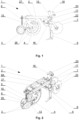
- fig. 1 presents the working section of an agricultural tilling set in a side view
- fig. 2 - a working section in a perspective view
- fig. 3 a working section with an elongated supporting frame in a perspective view
- fig. 4 the working section as in fig. 3 in top view
- fig. 5 the working section in a side view with the splitting and tearing discs and cultivation firming discs offset from each other
- fig. 6 - the working section in a side view showing the loosening tine bracket
- fig. 7 working section with raised loosening tine in partial side view of the loosening tine bracket and in partially cross-section through the beam
- fig. 8 shock absorber of splitting and tearing discs in perspective view.
- the working section 1 of the agricultural tilling set includes working tools mounted on the supporting frame 2, in the form of a pair of inclined relative to each other splitting and tearing discs 3, a disc coulter 4 with embossing, a loosening tine 5 with a fertilizer coulter 6 and a pair of cultivating firming discs 7.
- Working sections 1 are intended for agricultural cultivators for strip tillage and soil strip preparation for seeding.
- the working sections 1 may have a short ( Figs. 1, 2 ) or long ( Figs. 3, 4 ) supporting frame 2 constituting the part to which all other elements and working tools of the working section 1 are attached. All elements and working tools attached to the supporting frame 2 are the same regardless of its length.
- the supporting frame 2 is provided with means for connecting to the agricultural tilling set.
- mounting holes 8A made in the supporting frame 2.
- Appropriate means for connecting to the agricultural tilling set are fastened in the mounting holes 8A, and these may be, for example, clamping yokes or clamps.
- the pair of inclined relative to each other splitting and tearing discs 3 have a common body 8, which is connected by a shock absorber 9 with the supporting frame 2.
- the splitting and tearing discs 3 are mounted in the front part of the working section 1, and their task is to clean the soil strip.
- the shock absorber 9 ( fig. 8 ) has a shank 10 with a coil spring 11 mounted thereon, resting on the one side of the upper retaining clamp 12A and, on the other side, the lower retaining clamp 12B.
- the shank 10 is fixed from the top of the supporting frame 2 through the upper retaining clamp 12A with the mounting arms 14A entering into the open-top socket in the supporting frame 2.
- the shank 10 has through holes 13 along its length for adjusting the contact force of the splitting and tearing discs.
- the lower retaining clamp 12B has a through hole, so that a locking pin 14 with a hole for securing pin extends through selected through holes 13 of the shank 10 of the shock absorber 9 and the through hole of lower retaining clamp 12B.
- the soil layer is cut up to 100 mm through the disc coulter 4 with embossing.
- the disc coulter 4 is connected to the supporting frame 2 with a bracket 15.
- the disc coulter 4 itself has the form of a rim with a corrugated cutting edge, which increases the scope of work in the lateral direction, and the incision formed in the soil in the top view has a wave-like shape.
- the corrugations on the cutting edge improve the resistance of the disc coulter 4 to deformations.
- a bracket 16 of loosening tine 5 is mounted in the part of the supporting frame 2, behind the disc coulter 4, a bracket 16 of loosening tine 5 is mounted.
- the supporting frame 2 and bracket 16 of loosening tine 5 are connected to each other in a non-detachable manner, for example by welding.
- a loosening tine 5 is rotatably mounted with a fertilizer coulter 6 attached to it in the rear part.
- the loosening tine 5 has replaceable working elements, and its task is to deeply loosen the cultivated soil, down to a depth of 350 mm.
- a pair of monolithic brackets 17 is mounted on the bracket 16 of the loosening tine 5, between which a hydraulic actuator 18 is mounted, connected to the loosening tine 5.
- the position of the loosening tine 5 is controlled with the use of the hydraulic actuator 18.
- the hydraulic actuator 18 piston rod extended With the hydraulic actuator 18 piston rod extended, the loosening tine 5 is unfolded and is in the working position, while with the piston rod of the hydraulic actuator 18 retracted, the loosening arm is folded and it is in the transport position.
- the use of a hydraulic actuator 18 protects the loosening tine 5 against overload.
- the holder 19 with the mounted fertilizer distributor 20 is connected to the bracket 16 of the loosening arm 5.
- the fertilizer distributor 20 has three inlet openings for the connection of the fertilizer supply lines and an outlet for connection of the supply line connecting the fertilizer distributor 20 with the fertilizer coulter 6.
- One of the inlet holes of the fertilizer distributor 20 has a venting function, whereby fertilizer supply lines can be connected to the two inlets.
- the fertilizer coulter 6, on the other hand, has an inlet for connecting a supply line from the fertilizer distributor, and the outlet of the fertilizer coulter 6 is designed to supply fertilizer to the soil, so that the fertilizer can be introduced along the entire cross-section of the cultivated strip.
- the fertilizer distributor 20 can supply different types of fertilizer to the fertilizer coulter 6, and even liquid fertilizer such as liquid manure or seeds. Two separate fertilizer tanks on the agricultural tilling set may be connected to the fertilizer distributor 20.
- a fertilizer coulter 6 connected to a fertilizer distributor 20 performs the task of evacuating air from the loosened soil.
- cultivating firming discs 7 Behind the loosening tine 5, with the supporting frame 2, also by means of the loosening tine 5 of bracket 16, there are connected the cultivating firming discs 7, which are divergent to each other.
- the task of the cultivating firming discs 7 is to close the gap formed by the loosening tine 5.
- a beam 21 with a square cross-section is embedded in the bracket 16 of the loosening tine 5.
- Each cultivating firming disc 7 is connected to the supporting frame 2 by means of the angular bracket 22 and by means of the bracket 16 of the loosening tine 5 and the beam 21.
- Each angular bracket 22 has a cultivating firming disc 7 attached at one end, and at the other end it is connected to a fixing clamp 23 mounted on the beam 21.
- the fixing clamp 23 can be appropriately adapted to the beam 21 without having to change the entire angular bracket 22. Between the beam 21 and the fixing clamps 23 of the angular brackets 22 there are placed four rubber shock absorbing elements 24 with a circular cross section. The fixing clamp 23 fully rests on the shock absorbing elements 24, which significantly reduces the vibrations transmitted from the cultivating firming discs 7 to the working section 1. In other embodiments, the shock-absorbing elements 24 may be made of plastics.
- the front edges of the splitting and tearing discs 3 are shifted relative to each other on a straight line parallel to the direction of movement of the working section 1. So arranged, the splitting and tearing discs 3 are automatically cleaned of soil and plant residues.
- the working section 1 it is also possible to arrange shifted mounting of the cultivating firming discs 7 ( Fig. 5 ). Then, the front edges of the cultivating firming discs 7 are shifted relative to each other on a straight line parallel to the direction of movement of the working section 1. It is also possible to mount the cultivating firming discs 7 without shifting, where the front edges of the cultivating firming discs 7 are located on a one straight line parallel to the direction of movement of the working section 1.
- each splitting and tearing disc 3 has an assigned cleaning scraper 25. Sliding mounting of the cleaning scraper 25 provides the possibility of easy adjustment of its position in relation to the splitting and tearing disc 3.
- cleaning of the working tools is also improved by cleaning scrapers 26 mounted on the holders connected to the bracket 15 of the disc coulter 4. Cleaning scrapers 26 clean the rim of the disc coulter 4 and the rolling surfaces of the splitting and tearing discs 3.
- the supporting frame 2 In the upper part of the supporting frame 2 there is an additional support 27 which supports the fixing of the working section 1 to the agricultural tilling set.
- the place of its fastening depends on the length of the supporting frame 2 - in case of a short supporting frame 2, the support 27 is mounted in the area above the disc coulter 4, and in case of a long supporting frame 2, the support 27 is located behind the fertilizer distributor 20.
Landscapes
- Life Sciences & Earth Sciences (AREA)
- Soil Sciences (AREA)
- Environmental Sciences (AREA)
- Engineering & Computer Science (AREA)
- Mechanical Engineering (AREA)
- Soil Working Implements (AREA)
Claims (8)
- Die Arbeitseinheit (1) eines landwirtschaftlichen Bodenbearbeitungsgeräts, das Arbeitswerkzeuge umfasst, die an einem Tragrahmen (2) montiert sind, insbesondere ein Paar zueinander geneigte Spalt- und Schneidscheiben (3), eine Scheibenschar (4), eine Lockerungszinke (5) mit einem Düngerschar (6), ein Paar Kultivierungs- und Verdichtungsscheiben (7), wobei an der Vorderseite des Tragrahmens (2) das Paar Spalt- und Schneidscheiben (3) an einem gemeinsamen Körper (8) montiert ist, der über einen Stoßdämpfer (9) mit dem Tragrahmen verbunden ist, und hinter diesem Paar von Spalt- und Schneidscheiben (3) weitere Arbeitswerkzeuge angebracht sind, wobei die Lockerungszinke (5) drehbar in Bezug auf den Tragrahmen montiert ist, der mit Mitteln zum Verbinden mit dem landwirtschaftlichen Bodenbearbeitungsgerät ausgestattet ist, wobei im Bereich des Tragrahmens (2) hinter dem Scheibenschar (4) eine Halterung (16) der Lockerungszinke (5) angebracht ist, in der die Lockerungszinke (5) drehbar gelagert ist und an der ein Paar monolithischer Halterungen (17) eines Betätigungselements (18) befestigt ist, in dem das Betätigungselement (18), das mit der Lockerungszinke (5) verbunden ist, angebracht ist, und jede Kultivierungs- und Verdichtungsscheibe (7) über einen Winkelhalter (22) mit dem Tragrahmen (2) verbunden ist.
- Die Arbeitseinheit nach Anspruch 1, dadurch gekennzeichnet, dass ein Träger (21), an dem die Winkelhalter (22) der Kultivierungs- und Verdichtungsscheiben (7) befestigt sind, mit stoßdämpfenden Elementen (24), insbesondere aus Gummi oder Kunststoff, die sich zwischen dem Träger (21) und den Winkelhaltern (22) befinden, in der Halterung (16) der Lockerungszinke (5) eingebettet ist.
- Die Arbeitseinheit nach Anspruch 1 oder 2, dadurch gekennzeichnet, dass an dem gemeinsamen Körper (8) der Spalt- und Schneidscheiben (3) verschiebbar montierte Reinigungsschaber (25) angebracht sind, wobei jeder davon jeweils einer der Spalt- und Schneidscheiben (3) zugeordnet ist.
- Die Arbeitseinheit nach einem der Ansprüche 1 bis 3 ist dadurch gekennzeichnet, dass die Vorderkanten der Spalt- und Schneidscheiben (3) oder der Kultivierungs- und Verdichtungsscheiben (7) relativ zueinander auf einer Linie parallel zur Bewegungsrichtung der Arbeitseinheit (1) verschoben sind.
- Die Arbeitseinheit nach einem der Ansprüche 1 bis 4, dadurch gekennzeichnet, dass der Stoßdämpfer (9), der den gemeinsamen Körper (8) der Spalt- und Schneidscheiben (3) befestigt, einen Schaft (10) mit Durchgangsbohrungen (13) und eine darauf montierte Schraubenfeder (11) aufweist, wobei die Schraubenfeder auf einer unteren Halteklemme (12B) mit einer Durchgangsbohrung ruht, und ein Sicherungsbolzen (14) mit einer Bohrung für einen Splint durch die Bohrungen (13) des Schafts (10) des Stoßdämpfers (9) und die untere Halteklemme (12B) geführt ist.
- Die Arbeitseinheit nach einem der Ansprüche 1 bis 5, dadurch gekennzeichnet, dass ein Halter (19) mit einem Düngerverteiler (20) an der Halterung (16) der Lockerungszinke (5) befestigt ist.
- Die Arbeitseinheit nach einem der Ansprüche 1 bis 6, dadurch gekennzeichnet, dass Reinigungsschaber (26) sowohl an den Spalt- und Schneidscheiben (3) als auch an der Scheibenschar (4) angebracht sind.
- Die Arbeitseinheit nach einem der Ansprüche 1 bis 7, dadurch gekennzeichnet, dass der Tragrahmen (2) eine Verstärkungsstütze (27) umfasst.
Applications Claiming Priority (2)
| Application Number | Priority Date | Filing Date | Title |
|---|---|---|---|
| PL129961U PL129961U1 (pl) | 2021-03-30 | 2021-03-30 | Sekcja robocza rolniczego agregatu uprawowego |
| PCT/IB2022/051926 WO2022208185A1 (en) | 2021-03-30 | 2022-03-04 | Working section of an agricultural tilling set |
Publications (3)
| Publication Number | Publication Date |
|---|---|
| EP4312487A1 EP4312487A1 (de) | 2024-02-07 |
| EP4312487B1 true EP4312487B1 (de) | 2025-02-19 |
| EP4312487C0 EP4312487C0 (de) | 2025-02-19 |
Family
ID=83459974
Family Applications (1)
| Application Number | Title | Priority Date | Filing Date |
|---|---|---|---|
| EP22718774.7A Active EP4312487B1 (de) | 2021-03-30 | 2022-03-04 | Arbeitsabschnitt eines landwirtschaftlichen bodenbearbeitungssatzes |
Country Status (3)
| Country | Link |
|---|---|
| EP (1) | EP4312487B1 (de) |
| PL (2) | PL129961U1 (de) |
| WO (1) | WO2022208185A1 (de) |
Family Cites Families (3)
| Publication number | Priority date | Publication date | Assignee | Title |
|---|---|---|---|---|
| US8327780B2 (en) * | 2009-10-16 | 2012-12-11 | Dawn Equipment Company | Agricultural implement having fluid delivery features |
| US10959369B2 (en) * | 2014-09-22 | 2021-03-30 | Rotacon Engineering Limited | Openers for seeders |
| CA3078506A1 (en) * | 2019-04-15 | 2020-10-15 | William E. Preller | Agricultural row unit for field cultivation |
-
2021
- 2021-03-30 PL PL129961U patent/PL129961U1/pl unknown
-
2022
- 2022-03-04 WO PCT/IB2022/051926 patent/WO2022208185A1/en not_active Ceased
- 2022-03-04 PL PL22718774.7T patent/PL4312487T3/pl unknown
- 2022-03-04 EP EP22718774.7A patent/EP4312487B1/de active Active
Also Published As
| Publication number | Publication date |
|---|---|
| PL4312487T3 (pl) | 2025-05-19 |
| EP4312487C0 (de) | 2025-02-19 |
| WO2022208185A1 (en) | 2022-10-06 |
| PL129961U1 (pl) | 2022-10-03 |
| EP4312487A1 (de) | 2024-02-07 |
Similar Documents
| Publication | Publication Date | Title |
|---|---|---|
| US8006775B2 (en) | Strip tillage implement | |
| US9271440B2 (en) | Parallel linkage opener with adjustable spring loaded packer wheel | |
| US7000708B2 (en) | Seedbed preparation implement having rotary disc with adjustable gang angle | |
| US6871709B2 (en) | Strip-till primary tillage system | |
| CA2149454C (en) | Combination cultivator and chemical applicator | |
| EP1182920B1 (de) | Landwirtschaftliche machine und vorrichtung | |
| US7156186B2 (en) | Strip-till conditioning rotary reel | |
| US20030141088A1 (en) | Rip strip primary tillage system | |
| CA2774065C (en) | Strip-till no build-up berm builder blade for strip-till farm implement | |
| CA2758221A1 (en) | Parallel linkage opener with adjustable spring loaded packer wheel | |
| KR20200110592A (ko) | 비료살포기와 배토기 및 로터베이터가 결합된 3공정 농작업기 | |
| EP4312487B1 (de) | Arbeitsabschnitt eines landwirtschaftlichen bodenbearbeitungssatzes | |
| EP1731011B1 (de) | Landwirtschaftlicher Werkzeugrahmen | |
| CZ27213U1 (cs) | Pracovníjednotka meziřádkového kypřiče | |
| NL9300659A (nl) | Grondbewerkingsmachine. | |
| NO143959B (no) | Anordning ved jordbruksredskap. | |
| AU2006201632B2 (en) | Seeder with trailing arm and hoe-type mid row bander | |
| RU2767523C1 (ru) | Комбинированный агрегат с универсальным почвообрабатывающим устройством | |
| US20250000001A1 (en) | Striptill row unit | |
| RU48142U1 (ru) | Почвообрабатывающее орудие | |
| EP3607808B1 (de) | Arbeitsgerät zur bodenvorbereitung | |
| CA2449537C (en) | Rip strip primary tillage system | |
| CA3052717A1 (en) | Sowing coulter with adjustable tear-open chisel | |
| US2789492A (en) | Hand guided, self-propelled cultivating device | |
| EP1641332B1 (de) | Sämaschine |
Legal Events
| Date | Code | Title | Description |
|---|---|---|---|
| STAA | Information on the status of an ep patent application or granted ep patent |
Free format text: STATUS: UNKNOWN |
|
| STAA | Information on the status of an ep patent application or granted ep patent |
Free format text: STATUS: THE INTERNATIONAL PUBLICATION HAS BEEN MADE |
|
| PUAI | Public reference made under article 153(3) epc to a published international application that has entered the european phase |
Free format text: ORIGINAL CODE: 0009012 |
|
| STAA | Information on the status of an ep patent application or granted ep patent |
Free format text: STATUS: REQUEST FOR EXAMINATION WAS MADE |
|
| 17P | Request for examination filed |
Effective date: 20231010 |
|
| AK | Designated contracting states |
Kind code of ref document: A1 Designated state(s): AL AT BE BG CH CY CZ DE DK EE ES FI FR GB GR HR HU IE IS IT LI LT LU LV MC MK MT NL NO PL PT RO RS SE SI SK SM TR |
|
| DAV | Request for validation of the european patent (deleted) | ||
| DAX | Request for extension of the european patent (deleted) | ||
| GRAP | Despatch of communication of intention to grant a patent |
Free format text: ORIGINAL CODE: EPIDOSNIGR1 |
|
| STAA | Information on the status of an ep patent application or granted ep patent |
Free format text: STATUS: GRANT OF PATENT IS INTENDED |
|
| GRAS | Grant fee paid |
Free format text: ORIGINAL CODE: EPIDOSNIGR3 |
|
| INTG | Intention to grant announced |
Effective date: 20241204 |
|
| GRAA | (expected) grant |
Free format text: ORIGINAL CODE: 0009210 |
|
| STAA | Information on the status of an ep patent application or granted ep patent |
Free format text: STATUS: THE PATENT HAS BEEN GRANTED |
|
| AK | Designated contracting states |
Kind code of ref document: B1 Designated state(s): AL AT BE BG CH CY CZ DE DK EE ES FI FR GB GR HR HU IE IS IT LI LT LU LV MC MK MT NL NO PL PT RO RS SE SI SK SM TR |
|
| REG | Reference to a national code |
Ref country code: GB Ref legal event code: FG4D |
|
| REG | Reference to a national code |
Ref country code: CH Ref legal event code: EP |
|
| REG | Reference to a national code |
Ref country code: DE Ref legal event code: R096 Ref document number: 602022010859 Country of ref document: DE |
|
| REG | Reference to a national code |
Ref country code: IE Ref legal event code: FG4D |
|
| U01 | Request for unitary effect filed |
Effective date: 20250310 |
|
| U07 | Unitary effect registered |
Designated state(s): AT BE BG DE DK EE FI FR IT LT LU LV MT NL PT RO SE SI Effective date: 20250317 |
|
| U20 | Renewal fee for the european patent with unitary effect paid |
Year of fee payment: 4 Effective date: 20250310 |
|
| PGFP | Annual fee paid to national office [announced via postgrant information from national office to epo] |
Ref country code: AT Payment date: 20250417 Year of fee payment: 4 |
|
| PG25 | Lapsed in a contracting state [announced via postgrant information from national office to epo] |
Ref country code: RS Free format text: LAPSE BECAUSE OF FAILURE TO SUBMIT A TRANSLATION OF THE DESCRIPTION OR TO PAY THE FEE WITHIN THE PRESCRIBED TIME-LIMIT Effective date: 20250519 |
|
| PGFP | Annual fee paid to national office [announced via postgrant information from national office to epo] |
Ref country code: PL Payment date: 20250310 Year of fee payment: 4 |
|
| PG25 | Lapsed in a contracting state [announced via postgrant information from national office to epo] |
Ref country code: ES Free format text: LAPSE BECAUSE OF FAILURE TO SUBMIT A TRANSLATION OF THE DESCRIPTION OR TO PAY THE FEE WITHIN THE PRESCRIBED TIME-LIMIT Effective date: 20250219 |
|
| PG25 | Lapsed in a contracting state [announced via postgrant information from national office to epo] |
Ref country code: IS Free format text: LAPSE BECAUSE OF FAILURE TO SUBMIT A TRANSLATION OF THE DESCRIPTION OR TO PAY THE FEE WITHIN THE PRESCRIBED TIME-LIMIT Effective date: 20250619 Ref country code: NO Free format text: LAPSE BECAUSE OF FAILURE TO SUBMIT A TRANSLATION OF THE DESCRIPTION OR TO PAY THE FEE WITHIN THE PRESCRIBED TIME-LIMIT Effective date: 20250519 |
|
| PG25 | Lapsed in a contracting state [announced via postgrant information from national office to epo] |
Ref country code: HR Free format text: LAPSE BECAUSE OF FAILURE TO SUBMIT A TRANSLATION OF THE DESCRIPTION OR TO PAY THE FEE WITHIN THE PRESCRIBED TIME-LIMIT Effective date: 20250219 |
|
| PG25 | Lapsed in a contracting state [announced via postgrant information from national office to epo] |
Ref country code: GR Free format text: LAPSE BECAUSE OF FAILURE TO SUBMIT A TRANSLATION OF THE DESCRIPTION OR TO PAY THE FEE WITHIN THE PRESCRIBED TIME-LIMIT Effective date: 20250520 |
|
| PG25 | Lapsed in a contracting state [announced via postgrant information from national office to epo] |
Ref country code: SM Free format text: LAPSE BECAUSE OF FAILURE TO SUBMIT A TRANSLATION OF THE DESCRIPTION OR TO PAY THE FEE WITHIN THE PRESCRIBED TIME-LIMIT Effective date: 20250219 |
|
| REG | Reference to a national code |
Ref country code: CH Ref legal event code: H13 Free format text: ST27 STATUS EVENT CODE: U-0-0-H10-H13 (AS PROVIDED BY THE NATIONAL OFFICE) Effective date: 20251023 |
|
| PG25 | Lapsed in a contracting state [announced via postgrant information from national office to epo] |
Ref country code: SK Free format text: LAPSE BECAUSE OF FAILURE TO SUBMIT A TRANSLATION OF THE DESCRIPTION OR TO PAY THE FEE WITHIN THE PRESCRIBED TIME-LIMIT Effective date: 20250219 |
|
| PG25 | Lapsed in a contracting state [announced via postgrant information from national office to epo] |
Ref country code: MC Free format text: LAPSE BECAUSE OF FAILURE TO SUBMIT A TRANSLATION OF THE DESCRIPTION OR TO PAY THE FEE WITHIN THE PRESCRIBED TIME-LIMIT Effective date: 20250219 |
|
| PLBE | No opposition filed within time limit |
Free format text: ORIGINAL CODE: 0009261 |
|
| STAA | Information on the status of an ep patent application or granted ep patent |
Free format text: STATUS: NO OPPOSITION FILED WITHIN TIME LIMIT |
|
| PG25 | Lapsed in a contracting state [announced via postgrant information from national office to epo] |
Ref country code: CH Free format text: LAPSE BECAUSE OF NON-PAYMENT OF DUE FEES Effective date: 20250331 |
|
| PG25 | Lapsed in a contracting state [announced via postgrant information from national office to epo] |
Ref country code: IE Free format text: LAPSE BECAUSE OF NON-PAYMENT OF DUE FEES Effective date: 20250304 |
|
| PGFP | Annual fee paid to national office [announced via postgrant information from national office to epo] |
Ref country code: CZ Payment date: 20251212 Year of fee payment: 5 |
|
| 26N | No opposition filed |
Effective date: 20251120 |