EP4312153A1 - Image forming apparatus, control method for image forming apparatus, and control program for image forming apparatus - Google Patents
Image forming apparatus, control method for image forming apparatus, and control program for image forming apparatus Download PDFInfo
- Publication number
- EP4312153A1 EP4312153A1 EP23186258.2A EP23186258A EP4312153A1 EP 4312153 A1 EP4312153 A1 EP 4312153A1 EP 23186258 A EP23186258 A EP 23186258A EP 4312153 A1 EP4312153 A1 EP 4312153A1
- Authority
- EP
- European Patent Office
- Prior art keywords
- nozzle
- discharge
- density
- image
- recording head
- Prior art date
- Legal status (The legal status is an assumption and is not a legal conclusion. Google has not performed a legal analysis and makes no representation as to the accuracy of the status listed.)
- Granted
Links
Images




Classifications
-
- G—PHYSICS
- G06—COMPUTING OR CALCULATING; COUNTING
- G06K—GRAPHICAL DATA READING; PRESENTATION OF DATA; RECORD CARRIERS; HANDLING RECORD CARRIERS
- G06K15/00—Arrangements for producing a permanent visual presentation of the output data, e.g. computer output printers
- G06K15/02—Arrangements for producing a permanent visual presentation of the output data, e.g. computer output printers using printers
- G06K15/027—Test patterns and calibration
-
- B—PERFORMING OPERATIONS; TRANSPORTING
- B41—PRINTING; LINING MACHINES; TYPEWRITERS; STAMPS
- B41J—TYPEWRITERS; SELECTIVE PRINTING MECHANISMS, i.e. MECHANISMS PRINTING OTHERWISE THAN FROM A FORME; CORRECTION OF TYPOGRAPHICAL ERRORS
- B41J2/00—Typewriters or selective printing mechanisms characterised by the printing or marking process for which they are designed
- B41J2/005—Typewriters or selective printing mechanisms characterised by the printing or marking process for which they are designed characterised by bringing liquid or particles selectively into contact with a printing material
- B41J2/01—Ink jet
- B41J2/21—Ink jet for multi-colour printing
- B41J2/2132—Print quality control characterised by dot disposition, e.g. for reducing white stripes or banding
- B41J2/2146—Print quality control characterised by dot disposition, e.g. for reducing white stripes or banding for line print heads
-
- B—PERFORMING OPERATIONS; TRANSPORTING
- B41—PRINTING; LINING MACHINES; TYPEWRITERS; STAMPS
- B41J—TYPEWRITERS; SELECTIVE PRINTING MECHANISMS, i.e. MECHANISMS PRINTING OTHERWISE THAN FROM A FORME; CORRECTION OF TYPOGRAPHICAL ERRORS
- B41J29/00—Details of, or accessories for, typewriters or selective printing mechanisms not otherwise provided for
- B41J29/38—Drives, motors, controls or automatic cut-off devices for the entire printing mechanism
-
- G—PHYSICS
- G06—COMPUTING OR CALCULATING; COUNTING
- G06K—GRAPHICAL DATA READING; PRESENTATION OF DATA; RECORD CARRIERS; HANDLING RECORD CARRIERS
- G06K15/00—Arrangements for producing a permanent visual presentation of the output data, e.g. computer output printers
- G06K15/02—Arrangements for producing a permanent visual presentation of the output data, e.g. computer output printers using printers
- G06K15/10—Arrangements for producing a permanent visual presentation of the output data, e.g. computer output printers using printers by matrix printers
- G06K15/102—Arrangements for producing a permanent visual presentation of the output data, e.g. computer output printers using printers by matrix printers using ink jet print heads
-
- B—PERFORMING OPERATIONS; TRANSPORTING
- B41—PRINTING; LINING MACHINES; TYPEWRITERS; STAMPS
- B41J—TYPEWRITERS; SELECTIVE PRINTING MECHANISMS, i.e. MECHANISMS PRINTING OTHERWISE THAN FROM A FORME; CORRECTION OF TYPOGRAPHICAL ERRORS
- B41J25/00—Actions or mechanisms not otherwise provided for
- B41J2025/008—Actions or mechanisms not otherwise provided for comprising a plurality of print heads placed around a drum
Definitions
- the present invention relates to an image forming apparatus, a control method for the image forming apparatus, and a control program for the image forming apparatus.
- an inkjet type image forming apparatus that forms an image by discharging (ejecting) ink from a nozzle formed in a recording head and landing the ink on a recording medium such as paper while relatively moving the recording head and the recording medium.
- an apparatus configuration for the purpose of improving the recording speed, an apparatus configuration is adopted in which a plurality of recording heads each having a nozzle row formed therein is arranged in a staggered manner along a direction intersecting the direction of the relative movement described above (that is, along a width direction of the recording medium (hereinafter referred to as "width direction")) to configure a long line head, and an image is formed by the long line head.
- Such an image forming apparatus can form an image by causing the line head to scan the recording paper only once along a conveyance direction (also referred to as a one-pass method).
- Patent Literature 2 JP 2008-294609 A
- the plurality of recording heads arranged in a staggered manner along the width direction is disposed such that adjacent recording heads overlap each other in the line head, and an overlapping portion in which discharge target regions overlap between other adjacent recording heads (hereinafter, simply referred to as an "overlapping portion") is formed at an end portion of the nozzle row of each recording head (see Figs. 1 and 3 ).
- Fig. 1 is a diagram illustrating an example of an arrangement aspect of two adjacent recording heads arranged in a line head and an example of a discharge aspect of ink discharged from each of the two adjacent recording heads.
- ink is discharged from both a nozzle of an upstream recording head (this means a recording head arranged on the upstream side in the conveyance direction in the line head.
- a nozzle of a downstream recording head this means a recording head arranged on the downstream side in the conveyance direction in the line head.
- the density of an image at the overlapping portion is adjusted.
- the amount of ink discharged from each recording head is the same, but, in actual use, the amount of ink discharged from each recording head has a slight difference between the recording heads due to individual differences among the recording heads and changes in the surrounding environment at that time.
- the slight difference between the recording heads causes a density difference between an image formed by the upstream recording head and an image formed by the downstream recording head.
- the ink is discharged from both the nozzle of the upstream recording head and the nozzle of the downstream recording head, and further, the ratio of the ink discharged from the nozzle of the upstream recording head and the ink discharged from the nozzle of the downstream recording head is changed stepwise from a center side toward an end portion side of the nozzle row, so that a sudden density difference between the image formed by the upstream recording head and the image formed by the downstream recording head is prevented from occurring. That is, each dot of the image formed by the nozzles at the overlapping portion of the recording heads is formed such that the ink discharged from the nozzle of the downstream recording head overlaps the ink discharged from the nozzle of the upstream recording head.
- the positional relationship between the recording heads in the line head may slightly deviate in the width direction (that is, nozzle arrangement direction) from the designed positional relationship.
- the total amount of ink discharged to the overlapping portion of the recording heads deviates from the assumption, and in the image formed by the nozzles of the overlapping portion of the recording heads, a black streak may occur due to excessively large discharge dots, or a white streak may occur due to excessively small discharge dots (hereinafter, collectively referred to as "streaky noise").
- Fig. 1 illustrates a state in which the positional relationship between recording heads in a line head is deviated to the side of being close to each other in the width direction from the designed positional relationship, and a black streak occurs in an image region formed by the nozzles of the overlapping portion of the recording heads.
- Fig. 1 illustrates a state in which the positional relationship between recording heads in a line head is deviated to the side of being close to each other in the width direction from the designed positional relationship, and a black streak occurs in an image region formed by the nozzles of the overlapping portion of the recording heads.
- the ink discharge amount from each nozzle of the recording head is set on the assumption that only a dot Pu1 formed by the nozzle of the upstream recording head and a dot Pd1 formed by the nozzle of the downstream recording head overlap, but due to the positional deviation, the dot Pu1 formed by the nozzle of the upstream recording head, a dot Pd2 formed by the nozzle of the downstream recording head, and a dot Pu2 formed by the nozzle of the upstream recording head and the dot Pd1 formed by the nozzle of the downstream recording head overlap each other, and the dots become excessively large at the overlapping portions.
- the present invention has been made in view of the problem described above, and an object is to provide an image forming apparatus, a control method for the image forming apparatus, and a control program for the image forming apparatus that enable appropriate adjustment of density of an image formed by nozzles of an overlapping portion of recording heads.
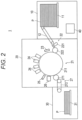
- Fig. 2 is a diagram illustrating a schematic configuration of the image forming apparatus 1.
- the image forming apparatus 1 is an inkjet type image forming apparatus that forms an image by discharging (ejecting) ink from a nozzle formed in a recording head and landing the ink on a recording medium P such as paper.
- the image forming apparatus 1 includes a sheet feeding portion 10, an image forming portion 20, a sheet ejection portion 30, and a control portion 40.
- the image forming apparatus 1 conveys the recording medium P stored in the sheet feeding portion 10 to the image forming portion 20, discharges ink on the recording medium P in the image forming portion 20 to record an image, and conveys the recording medium P on which the image is recorded to the sheet ejection portion 30.
- the image forming apparatus 1 records a color image on the recording medium P by outputting and superimposing four colors: yellow (Y), magenta (M), cyan (C), and black (K) on the recording medium P at a predetermined number of recording gradations.
- the image forming apparatus 1 is configured to be capable of storing a color image on the recording medium P in the high-speed printing mode described above.
- ink colors of yellow (Y), magenta (M), cyan (C), and black (K) will be abbreviated respectively as Y, M, C, and K.
- the recording medium P in addition to paper such as plain paper or coated paper, various media on which the ink landed on the surface can be fixed, such as of fabric or sheet-shaped resin, can be used.
- the sheet feeding portion 10 includes a sheet feeding tray 11 that stores the recording medium P, and a medium supply portion 12 that conveys and supplies the recording medium P from the sheet feeding tray 11 to the image forming portion 20.
- the medium supply portion 12 includes an annular belt whose inner side is supported by two rollers, and conveys the recording medium P from the sheet feeding tray 11 to the image forming portion 20 by rotating the rollers in a state where the recording medium P is placed on the belt.
- the image forming portion 20 includes a conveyance portion 21, a handover unit 22, a heating portion 23, head units 24, a fixing portion 25, an image reading portion 26, and a delivery portion 27.
- the conveyance portion 21 holds the recording medium P placed on the conveyance surface of a conveyance drum 211 having a cylindrical shape, and conveys the recording medium P on the conveyance drum 211 in the conveyance direction along the conveyance surface by rotating and moving the conveyance drum 211 about a rotation axis (cylindrical axis) extending in a direction orthogonal to the conveyance direction (that is, in the width direction of the recording medium).
- the conveyance drum 211 includes a claw portion and an air intake portion, which are not illustrated, for holding the recording medium P on the conveyance surface. An end portion of the recording medium P is pressed by the claw portion, and is sucked to the conveyance surface by the air intake portion so as to be held on the conveyance surface.
- the handover unit 22 is provided at a position between the medium supply portion 12 of the sheet feeding portion 10 and the conveyance portion 21, holds and picks up one end of the recording medium P conveyed from the medium supply portion 12 with a swing arm portion 221, and hands over the recording medium P to the conveyance portion 21 via a handover drum 222.
- the heating portion 23 is provided between the disposition position of the handover drum 222 and the disposition position of the head units 24, and heats the recording medium P so that the recording medium P conveyed by the conveyance portion 21 has a temperature within a predetermined temperature range.
- the heating portion 23 includes, for example, an infrared heater or the like, and energizes the infrared heater on the basis of a control signal supplied from the control portion 40 to cause the infrared heater to generate heat.
- the head units 24 record an image by discharging ink onto the recording medium P through a nozzle opening provided in an ink discharge surface facing the conveyance surface of the conveyance drum 211 at an appropriate timing according to the rotation of the conveyance drum 211 on which the recording medium P is held.
- the ink discharge surface and the conveyance surface are disposed to be spaced apart a predetermined distance.
- the image forming apparatus 1 of the present embodiment four head units 24 corresponding to the inks of four colors: Y, M, C, and K are arranged at predetermined intervals in the order of Y, M, C, and K colors from the upstream side in the conveyance direction of the recording medium P. Note that, since the four head units 24 according to the present embodiment have similar configurations, they are collectively referred to as the "head unit 24" below.
- the head unit 24 is used in position at the time of recording an image, and sequentially discharges the ink at predetermined intervals (conveyance direction intervals) at different positions in the conveyance direction according to the conveyance of the recording medium P, thereby recording an image by a single-pass method.
- Fig. 3 is a schematic diagram illustrating a configuration of the head unit 24.
- Fig. 3 illustrates a surface of the head unit 24 facing an outer peripheral surface of the conveyance drum 211.
- the head unit 24 includes four recording heads 240a to 240d attached to an attachment member 244.
- a plurality of image forming elements each including a pressure chamber (not illustrated) for storing ink, a piezoelectric element (not illustrated) provided on a wall surface of the pressure chamber, and a nozzle 243 communicating with the pressure chamber is provided in a line along the width direction of the recording medium P.
- the pressure chamber when a drive signal for deforming and operating the piezoelectric element is input, the pressure chamber is deformed by the deformation of the piezoelectric element, the pressure in the pressure chamber changes, and the ink is discharged from the nozzle 243 communicating with the pressure chamber.
- ink droplets of the liquid amount corresponding to the pixel value of the image data are discharged from the nozzle 243 toward the recording medium P, and an image is formed on the recording medium P carried on the conveyance drum 211.
- the four recording heads 240a to 240d are disposed in a staggered manner such that disposition ranges in the width direction of the recording medium P (nozzle row direction of recording heads 240) are connected without discontinuity.
- the four recording heads 240a to 240d are arranged such that, regarding a pair of recording heads 240 adjacent to each other, among the plurality of nozzles 243 (nozzle group) provided in each, the disposition ranges of a nozzle of one recording head 240 in the vicinity of an end portion on one side and a nozzle of the other recording head 240 in the vicinity of an end portion on the other side overlap each other in the nozzle row direction. That is, an overlapping portion R in which the discharge target regions overlap each other between adjacent other recording heads 240 is set at the end portion of the nozzle row of each recording head 240.
- the recording heads 240a and 240c arranged on the upstream side in the conveyance direction are referred to as “upstream recording heads 240”
- the recording heads 240b and 240d arranged on the downstream side in the conveyance direction are referred to as “downstream recording heads 240”.
- the recording head 240 when they are not distinguished, they are simply referred to as the "recording head 240".
- a nozzle corresponding to the overlapping portion R within the nozzle row formed in each recording head 240 is also referred to as an "overlapping portion nozzle 243" or an “end portion nozzle 243", and a nozzle not corresponding to the overlapping portion R within the nozzle row formed in each recording head 240 is also referred to as a "central nozzle 243".
- the disposition range of the nozzles 243 included in the head unit 24 in the width direction of the recording medium P covers the entire width in the width direction of the recording medium P in a region where an image is formed in the recording medium P conveyed by the conveyance drum 211, and the head unit 24 is used by being fixed to the rotation shaft of the conveyance drum 211 at the time of forming the image. That is, the head unit 24 constitutes a line head capable of discharging the ink over an image formable width in the width direction of the recording medium P with respect to the recording medium P.
- the recording head 240 includes an ink heating portion (not illustrated) that heats the ink stored in the recording head 240, and discharges the heated and sol-like ink.
- an ink heating portion (not illustrated) that heats the ink stored in the recording head 240, and discharges the heated and sol-like ink.
- an ultraviolet-curable hot-melt ink composition can be used as the ink discharged from the nozzles 243 of the recording heads 240.
- the fixing portion 25 includes an energy ray emission portion disposed over the entire width in the width direction of the recording medium P in the conveyance portion 21, and irradiates the recording medium P placed on the conveyance portion 21 with an energy ray such as an ultraviolet ray from the energy ray emission portion to cure and fix the ink discharged on the recording medium P.
- the energy ray emission portion of the fixing portion 25 is disposed to face the conveyance surface between the disposition positions of the head units 24 and the disposition position of a handover drum 271 of the delivery portion 27 in the conveyance direction.
- the image reading portion 26 is disposed facing the drum surface of the conveyance drum 211 on the downstream side in the conveyance direction of the position for fixing the image by the fixing portion 25.
- the image reading portion 26 reads the density of an image including a test image for density measurement, which will be described below, formed on the recording medium P conveyed by the conveyance drum 211.
- the image reading portion 26 sends data of the read image to the control portion 40 as imaging data.
- the image reading portion 26 includes, for example, a combination of a light source that irradiates the recording medium P conveyed by the conveyance drum 211 with light and a sensor portion that detects the intensity of reflected light from the recording medium P on the basis of the light emitted from the light source to the recording medium P.
- the sensor portion is, for example, a line sensor in which a plurality of detection elements (pixels) is arranged in the width direction of the recording medium P.
- the sensor portion includes, for example, a charge coupled device (CCD) type imaging element, a complementary metal oxide semiconductor (CMOS) type imaging element, or the like, and can acquire a formed image on the recording medium P for each of a plurality of wavelength components, for example, at three wavelengths of red (R), green (G), and blue (B).
- CCD charge coupled device
- CMOS complementary metal oxide semiconductor
- the delivery portion 27 includes a belt loop 272 having an annular belt whose inner side is supported by two rollers, and the handover drum 271 having a cylindrical shape that hands over the recording medium P from the conveyance portion 21 to the belt loop 272, and conveys the recording medium P handed over from the conveyance portion 21 onto the belt loop 272 by the handover drum 271 with the belt loop 272 and sends the recording medium P to the sheet ejection portion 30.
- the sheet ejection portion 30 includes a sheet ejection tray 31 having a plate shape on which the recording medium P sent from the image forming portion 20 by the delivery portion 27 is placed. Then, the sheet ejection portion 30 places the recording medium P on which an image is formed on the sheet ejection tray 31.
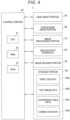
- Fig. 4 is a block diagram illustrating a main functional configuration of the image forming apparatus 1.
- the image forming apparatus 1 includes the control portion 40, a head drive portion 50, a conveyance drive portion 60, an image processing portion 70, an input/output interface 80, and a storage portion 100.
- the control portion 40 includes a central processing unit (CPU) 41, random access memory (RAM) 42, and read only memory (ROM) 43, and integrally controls the entire operation of the image forming apparatus 1.
- the control portion 40 receives image data transmitted from an external apparatus (for example, a personal computer) connected to a communication network such as a local area network (LAN) or a wide area network (WAN) via the input/output interface 80, and causes the head drive portion 50, the conveyance drive portion 60, the image processing portion 70, and the like to perform an operation of forming an image on the recording medium P on the basis of the image data (input image data).
- LAN local area network
- WAN wide area network
- the CPU 41 reads various control programs and setting data stored in the ROM 43, causes the RAM 42 to store them, and execute the programs to perform various arithmetic processing.
- the RAM 42 provides a working memory space for the CPU 41, and stores temporary data.
- the RAM 42 may include, for example, nonvolatile memory.
- the ROM 43 stores various control programs executed by the CPU 41, setting data, and the like. Note that, instead of the ROM 43, rewritable nonvolatile memory such as electrically erasable programmable read only memory (EEPROM) or flash memory may be used.
- EEPROM electrically erasable programmable read only memory
- test print execution portion 40a discharge correction amount setting portion 40b, and driving condition determination portion 40c (see Fig. 6 )) to be described below of the control portion 40 is achieved, for example, by the CPU 41 referring to the control program and various data stored in the ROM 43, the RAM 42, the storage portion 100, and the like.
- some or all of the functions may be achieved by processing by a digital signal processor (DSP) or a dedicated hardware circuit (for example, ASIC or FPGA) instead of or in addition to the processing by the CPU 41.
- DSP digital signal processor
- ASIC application specific integrated circuit
- the head drive portion 50 supplies a drive signal corresponding to the image data to the image forming element of the head unit 24 at an appropriate timing on the basis of control by the control portion 40, and causes the nozzles of the head unit 24 to discharge the ink of an amount corresponding to the pixel value of the image data.
- the head drive portion 50 receives image data subjected to image processing by the control portion 40, and forms a predetermined image on the recording medium P on the basis of the image data. Specifically, under the control of the control portion 40, the head drive portion 50 applies, to the head unit 24, a drive voltage (which means a piezoelectric drive voltage for driving the image forming element. The same applies hereinafter) according to the pixel value of the image data. Thus, the ink of a liquid amount corresponding to the pixel value of the image data is discharged (ejected) from the nozzle 243 of the recording head 240, and is landed at a predetermined position on the recording medium P to form an image.
- a drive voltage which means a piezoelectric drive voltage for driving the image forming element. The same applies hereinafter
- the liquid amount of the ink discharged from the nozzle 243 of the recording head 240 is basically adjusted on the basis of the voltage level of the drive voltage applied from the head drive portion 50 to the individual image forming element of the recording head 240, but can also be adjusted by correcting the discharge gradation of the individual nozzle 243 of the recording head 240 (the number of times of discharge for discharging per pixel region (multi-drop method)).
- the conveyance drive portion 60 supplies a drive signal to a conveyance drum motor provided in the conveyance drum 211 on the basis of the control signal supplied from the control portion 40, and rotates the conveyance drum 211 at a predetermined speed and timing.
- the conveyance drive portion 60 supplies a drive signal to a motor for operating the medium supply portion 12, the handover unit 22, and the delivery portion 27 on the basis of the control signal supplied from the control portion 40, and causes the recording medium P to be supplied to the conveyance portion 21 and discharged from the conveyance portion 21.
- the image processing portion 70 performs predetermined image processing on the image data stored in the storage portion 100, and causes the storage portion 100 to store the obtained image data.
- This image processing includes color conversion processing, gradation correction processing, pseudo halftone processing, and the like in addition to correction processing of correcting image data by applying a correction table or the like, which is not illustrated, to the image data.
- the input/output interface 80 is connected to an input/output interface of an external apparatus (for example, a personal computer), and mediates transmission and reception of data between the control portion 40 and the external apparatus.
- the input/output interface 80 includes, for example, any one of various serial interfaces and various parallel interfaces, or a combination thereof.
- the storage portion 100 stores print job data 100a, test image data 100b, conversion table data 100c, correction data 100d, and the like.
- a hard disk drive (HDD), dynamic random access memory (DRAM), or the like is used as the storage portion 100.
- the print job data 100a is data input from the external apparatus via the input/output interface 80, and includes, for example, job identification information, image data to be printed, setting data related to image recording, status data related to a status (for example, the number of sheets on which printing is completed) during execution of a print job, and the like.
- the test image data 100b is image data of a test image for density measurement.
- the test image data 100b is referred to at the time of test printing, for example, and is set so that a predetermined amount of ink is discharged from all the nozzles 243 of the four recording heads 240a to 240d, and for example, a solid image with a predetermined gradation is used.
- the conversion table data 100c is table data for the control portion 40 (discharge correction amount setting portion 41) to be described below to calculate the discharge correction amount of the ink of the nozzle 243 of the overlapping portion R from the read information of the test image on the recording medium P formed by the test printing (see Figs. 7A and 7B to be described below).
- the correction data 100d is data related to the discharge correction amount of the ink of the nozzle 243 of the overlapping portion R calculated using the conversion table data 100c.
- the correction data 100d separately stores, for example, data to be applied to each of the plurality of recording heads 240a to 240d.
- the correction data 100d is prepared to correct the ink discharge amount of each of the plurality of recording heads 240a to 240d determined by the control portion 40 on the basis of the pixel value of the image data to be printed at the time of performing the actual printing.
- the discharge amount of the ink from the nozzle of the overlapping portion R of the plurality of recording heads 240a to 240d is adjusted to the discharge amount in which the streaky noise does not occur in the image by the correction data 100d.
- control portion 40 Accordingly, a detailed configuration of the control portion 40 according to the present embodiment will be described with reference to Figs. 5A to 10.
- the applicant of the present application has proposed a method of forming a test image on the recording medium P by test printing and performing feedback from the density of the image formed on the recording medium P to the discharge amount of the nozzles 243 in JP 2008-294609 A .
- the positional relationship between the recording heads 240 in the head unit deviates in the width direction (that is, the arrangement direction of the nozzles) from the designed positional relationship, the density of the image formed in the overlapping portion R can be adjusted.
- JP 2008-294609 A As a result of intensive studies by the inventors of the present application, by the method described in JP 2008-294609 A , there is a difference in the density change amount depending on whether the discharge amount of the upstream recording head 240 or the downstream recording head 240 is increased or decreased, and it has been found that the density correction cannot be appropriately performed by the method of performing feedback to the discharge amount of the nozzle of the upstream recording head 240 or the downstream recording head 240 without considering such a viewpoint.
- JP 2008-294609 A also discloses a method of correcting the density of the overlapping portion R by changing the "number of non-discharge pixels", but it has been found that when the density correction is performed by such a method, discomfort due to roughness is conspicuous.
- Figs. 5A to 5C are diagrams describing an ink landing aspect ( Fig. 5B ) when the density is corrected by the discharge amount Down of the nozzle 243 of the overlapping portion R of the downstream recording head 240 and an ink landing aspect ( Fig. 5C ) when the density is corrected by the discharge amount Down of the nozzle 243 of the overlapping portion R of the upstream recording head 240 in a state where a black streak occurs in an image formed on the recording medium P ( Fig. 5A ).
- Fig. 5A illustrates a state where the ink discharge amount from each nozzle 243 of the recording head 240 is set on the assumption that only a dot A1 formed by the nozzle 243 of the upstream recording head 240 and a dot B 1 formed by the nozzle 243 of the downstream recording head 240 overlap, but due to the positional deviation, dots A1 and A2 formed by the nozzle 243 of the upstream recording head 240 and dots B 1 and B2 formed by the nozzle 243 of the downstream recording head 240 are in a state of overlapping each other, and the dots become excessively large at the overlapping portions R.
- JP 2008-294609 A proposed by the applicants of the present application, a test image is printed on the recording medium P, and the density of an image formed in the overlapping portion R (that is, the end portion nozzle 243 of the recording head 240) on the recording medium P and the density of an image formed by a nozzle (that is, the central nozzle 243 of the recording head 240) of a portion other than the overlapping portion R on the recording medium P are detected. Then, a state in which a black streak occurs or a state in which a white streak occurs in an image formed on the recording medium P is detected on the basis of a difference value between these densities.
- the correction target is randomly determined without considering whether the nozzle 243 to be corrected for the ink discharge amount exists in the upstream recording head 240 in the head unit 24 or in the downstream recording head 240 in the head unit 24.
- a state in which a black streak occurs in an image formed on the recording medium P is considered. Note that, in this case, in order to eliminate the black streak, it is necessary to perform correction to reduce the discharge amount of the ink discharged from the nozzle 243 of the overlapping portion R in order to reduce the density of the image formed by the nozzle 243 of the overlapping portion R.
- the ink when the ink is discharged from the upstream recording head 240, the ink lands on a flat recording medium P, and forms dots A1, A2, and the like at pixel positions of the recording medium P.
- the ink when the ink is discharged from the downstream recording head 240, the ink lands so as to overlap the previously formed dots A1 and A2 in the overlapping portion R, and forms dots B 1 and B2 spreading around the dots A1 and A2 to fill the paper surface.
- the density change amount of the image formed by the nozzle 243 of the overlapping portion R is smaller than the case where the density is corrected by the discharge amount Down of the nozzle 243 of the overlapping portion R of the upstream recording head 240. Therefore, a black streak may remain in the image even after the correction.
- the dot diameter of the combined dot of the dot A2 and the dot B 1 (or the combined dot of the dot A1 and the dot B2) becomes too small, or the combined dot is disposed at a biased position in the pixel region of the recording medium P, and as a result, a white streak may occur in the image.
- the discharge amount Down of the nozzle of the overlapping portion R of the downstream recording head 240 and the discharge amount Down of the nozzle of the overlapping portion R of the upstream recording head 240 are the same amount (that is, the correction amounts are the same)
- the magnitude of the correction amount a state in which the dots A1 and A2 formed by the ink discharged from the upstream recording head 240 are isolated occurs, or the dot diameter of the combined dot of the dot A2 and the dot B 1 (and the combined dot of the dot A1 and the dot B2) remains large, and there is a possibility that the density of the image cannot be set to a desired value.
- both the discharge amount Down of the nozzle 243 of the overlapping portion R of the downstream recording head 240 and the discharge amount Down of the nozzle 243 of the overlapping portion R of the upstream recording head 240 are performed to correct the image density. Then, at this time, the correction amount (here, the correction in the Down direction) of the discharge amount of the nozzle 243 of the overlapping portion R of the downstream recording head 240 is set to be larger than the correction amount (here, the correction in the Down direction) of the discharge amount of the nozzle of the overlapping portion R of the upstream recording head 240.
- the dots A1 and A2 formed by the ink discharged from the upstream recording head 240 remain in an isolated state, or when the size of the dots A1 and A2 becomes too large, the density of the image cannot be appropriately adjusted. Then, at this time, in a case where the discharge amount Up of the nozzle of the overlapping portion R of the downstream recording head and the discharge amount Up of the nozzle of the overlapping portion R of the upstream recording head 240 are the same amount (that is, the correction amounts are the same), depending on the magnitude of the correction amount, the dots A1 and A2 formed by the ink discharged from the upstream recording head remain in an isolated state, or the dot diameter of the combined dot of the dot A2 and the dot B 1 (and the combined dot of the dot A1 and the dot B2) becomes excessively large, and there is a possibility that the density of the image cannot be set to a desired value.
- both the discharge amount Up of the nozzle 243 of the overlapping portion R of the downstream recording head 240 and the discharge amount Up of the nozzle of the overlapping portion R of the upstream recording head 240 are performed to correct the image density. Then, at this time, the correction amount (here, the correction in the Up direction) of the discharge amount of the nozzle 243 of the overlapping portion R of the downstream recording head 240 is set to be smaller than the correction amount (here, the correction in the Up direction) of the discharge amount of the nozzle 243 of the overlapping portion R of the upstream recording head 240.
- Fig. 6 is a diagram illustrating an example of functional blocks of the control portion 40.
- the control portion 40 includes the test print execution portion 40a, the discharge correction amount setting portion 40b, and the driving condition determination portion 40c.
- test print execution portion 40a is a functional unit that forms a test image for density detection on the recording medium P using the head unit 24 and causes the image reading portion 26 to read density information of the test image formed on the recording medium P.
- the discharge correction amount setting portion 40b is a functional unit that calculates, at the time of test printing, for each of the plurality of recording heads 240 (here, four recording heads 240a to 240d), a difference value between the density of the image formed using the end portion nozzle 243 corresponding to the overlapping portion R in the nozzle row in the recording head 240 and the density of the image formed using the central nozzle 243 not corresponding to the overlapping portion R in the nozzle row in the recording head 240 from the density information of the read test image, and sets the discharge correction amount per discharge at the time of discharging the ink from the end portion nozzle 243 at the time of actual printing on the basis of the difference value.
- the discharge correction amount setting portion 40b is configured to convert the difference value into the discharge correction amount with reference to a predetermined conversion table ( Fig. 7B described below).
- the predetermined conversion table includes a first conversion table applied to the upstream recording head 240 (hereinafter, referred to as a "first conversion table”) and a second conversion table applied to the downstream recording head 240 (hereinafter, referred to as a "second conversion table”), and the two different tables are prepared.
- the discharge correction amount setting portion 40b is configured to refer to the first conversion table when calculating the discharge correction amount to be applied to the end portion nozzle 243 of the upstream recording head 240 and refer to the second conversion table when calculating the discharge correction amount to be applied to the end portion nozzle 243 of the downstream recording head 240.
- the driving condition determination portion 40c calculates the discharge amount of ink by each nozzle 243 of the nozzle row of each of the plurality of recording heads 240 (here, four recording heads 240a to 240d) on the basis of the pixel value of the image data to be printed, and determines the driving condition (for example, a piezoelectric drive voltage applied to individual image forming element) of each of the plurality of recording heads 240.
- the driving condition determination portion 40c corrects the driving condition (for example, a piezoelectric drive voltage applied to individual image forming element) of each of the plurality of recording heads 240 on the basis of the discharge correction amount set for each of the plurality of recording heads 240, and adjusts the discharge amount of the ink by the end portion nozzle 243 of each of the plurality of recording heads 240.
- the driving condition for example, a piezoelectric drive voltage applied to individual image forming element
- the driving condition determination portion 40c determines the driving condition of each recording head 240 such that, at the overlapping portion, for example, both the nozzle 243 of the upstream recording head 240 and the nozzle 243 of the downstream recording head 240 are caused to discharge the ink and each dot of the image formed by the nozzles 243 of the overlapping portion is formed by overlapping the ink discharged from the nozzle 243 of the downstream recording head 240 on the ink discharged from the nozzle 243 of the upstream recording head 240.
- Figs. 7A to 7C are diagrams describing an example of a method of correcting the ink discharge amount of the nozzle 243 of the overlapping portion R by the discharge correction amount setting portion 40b.
- Figs. 7A, 7B, and 7C are examples of table data referred to by the discharge correction amount setting portion 40b at the time of correction.
- Figs. 7A, 7B, and 7C for convenience of description, only table data referred to in a case where the density of the image region formed by the end portion nozzle 243 of the recording head 240 is higher than the density of the image region formed by the central nozzle 243 of the recording head 240 (that is, a state where a black streak occurs in the image) is illustrated.
- Fig. 7A is a diagram illustrating an example of table data (hereinafter, referred to as "density correction value calculation table data”) for calculating a density correction value ⁇ Dc of the end portion nozzle 243 from a difference value ⁇ D (hereinafter referred to as "central portion/end portion density difference ⁇ D") between the density of an image formed using the end portion nozzle (that is, the nozzle corresponding to the overlapping portion R in the nozzle row of the recording head 240) 243 of the recording head 240 and the density of an image formed using the central nozzle (that is, the nozzle corresponding to a portion other than the overlapping portion R in the nozzle row of the recording head 240) 243 of the recording head 240.
- a difference value ⁇ D hereinafter referred to as "central portion/end portion density difference ⁇ D”
- the central portion/end portion density difference ⁇ D and the density correction value ⁇ Dc are set to different values, but the central portion/end portion density difference ⁇ D and the density correction value ⁇ Dc may be set to the same value. In this case, the density correction value calculation table data is unnecessary.
- Fig. 7B is a diagram illustrating an example of table data (hereinafter, referred to as "discharge correction amount calculation table data") for calculating discharge correction amount ⁇ LvcU (discharge correction amount applied to the upstream recording head 240) and ⁇ Lvc_D (discharge correction amount applied to the downstream recording head 240) per discharge by the end portion nozzle 243 from the density correction value ⁇ Dc of the end portion nozzle 243.
- discharge correction amount calculation table data for calculating discharge correction amount ⁇ LvcU (discharge correction amount applied to the upstream recording head 240) and ⁇ Lvc_D (discharge correction amount applied to the downstream recording head 240) per discharge by the end portion nozzle 243 from the density correction value ⁇ Dc of the end portion nozzle 243.
- the discharge correction amounts ⁇ Lvc_U and ⁇ Lvc_D are set in the direction of decreasing the discharge amount of ink by the end portion nozzle 243.
- the discharge correction amounts ⁇ Lvc_U and ⁇ Lvc_D are set in the direction of increasing the discharge amount of ink by the end portion nozzle 243.
- table data (first conversion table) (solid line in Fig. 7B ) applied to the upstream recording head 240 and table data (second conversion table) (dotted line in Fig. 7B ) applied to the downstream recording head 240.
- the discharge correction amount (that is, the discharge correction amount per unit amount of the central portion/end portion density difference ⁇ D) ⁇ Lvc_U per unit amount of the density correction value ⁇ Dc of the first conversion table is set to be smaller than the discharge correction amount (that is, the discharge correction amount per unit amount of the central portion/end portion density difference ⁇ D) ⁇ Lvc_D per unit amount of the density correction value ⁇ Dc of the second conversion table.
- the discharge correction amount (that is, the discharge correction amount per unit amount of the central portion/end portion density difference ⁇ D) ⁇ Lvc_U per unit amount of the density correction value ⁇ Dc of the first conversion table is set to be larger than the discharge correction amount (that is, the discharge correction amount per unit amount of the central portion/end portion density difference ⁇ D) ⁇ Lvc D per unit amount of the density correction value ⁇ Dc of the second conversion table.
- a function (that is, graph characteristics) set in the density correction value calculation table data and a function (that is, graph characteristics) set in the discharge correction amount calculation table data change according to the viscosity characteristic of the gel-like ink, the distance in the conveyance direction between the upstream recording head 240 and the downstream recording head 240, the ink discharge characteristic of the recording head 240 itself, the time from when the ink is discharged by the recording head 240 to when the fixing processing is performed by the fixing portion 25, and the like. Therefore, these pieces of data are set in advance for each type of the image forming apparatus 1 using experimental data and simulation.
- Fig. 7C is a diagram illustrating an example of table data (hereinafter, referred to as "drive voltage correction table data") for calculating the correction amount of the piezoelectric drive voltage of the end portion nozzle 243 from the discharge correction amounts ⁇ Lvc_U and ⁇ Lvc_D per discharge by the end portion nozzle 243.
- drive voltage correction table data the same table data is applied to both the case of application to the discharge correction amount ⁇ Lvc_U and the case of application to the discharge correction amount ⁇ Lvc_D.
- Fig. 8 is a flowchart describing an example of discharge correction amount calculation processing in the control portion 40 (here, processing of the test print execution portion 40a and the discharge correction amount setting portion 40b).
- the control portion 40 When setting the ink discharge correction amount at the overlapping portion R, the control portion 40 first refers to test image data 100a stored in the storage portion 100, and forms a test image for density detection on the recording medium P using the head unit 24 as test printing (step S 101). For example, at the time of test printing, the control portion 40 causes all the nozzles 243 of the four recording heads 240 to discharge a predetermined amount of ink according to the test image data 100a.
- control portion 40 causes the image reading portion 26 to read density information of the test image formed on the recording medium P (step S102).
- control portion 40 calculates a difference value (central portion/end portion density difference ⁇ D) between the density of the image formed using the end portion nozzle 243 corresponding to the overlapping portion R in the nozzle row of the recording head 240 and the density of the image formed using the central nozzle 243 not corresponding to the overlapping portion R in the nozzle row of the recording head 240 from the density information of the test image formed on the recording medium P read by the image reading portion 26 (step S103).
- a difference value central portion/end portion density difference ⁇ D
- control portion 40 calculates a density correction amount ⁇ Dc of the image formed using the end portion nozzle 243 of the recording head 240 from the central portion/end portion density difference ⁇ D calculated in step S103 with reference to the density correction value calculation table data as illustrated in Fig. 7A (step S104).
- the control portion 40 calculates the central portion/end portion density difference ⁇ D (that is, the density correction amount ⁇ Dc) for the image region formed by each of the four recording heads 240a to 240d.
- ⁇ D that is, the density correction amount ⁇ Dc
- the control portion 40 calculates the central portion/end portion density difference ⁇ D (that is, the density correction amount ⁇ Dc) for the image region formed by each of the four recording heads 240a to 240d.
- the density of each of the image region formed using the nozzles 243 of the overlapping portion R between the recording head 240a and the recording head 240b, the image region formed using the nozzles 243 of the overlapping portion R between the recording head 240b and the recording head 240c, and the image region formed using the nozzles 243 of the overlapping portion R between the recording head 240c and the recording head 240d often differs depending on the deviation aspect of the positional relationship between the recording heads 240a to 240d in the head unit 24.
- control portion 40 calculates the discharge correction amounts ⁇ Lvc_U and ⁇ Lvc_D of the ink of the end portion nozzle 243 for each of the plurality of recording heads 240 with reference to the discharge correction amount calculation table data as illustrated in Fig. 7B from the density correction amount ⁇ Dc calculated in step S 104 (step S105).
- step S105 the control portion 40 calculates the discharge correction amount ⁇ Lvc_U of the ink of the end portion nozzle 243 by applying the first conversion table of the discharge correction amount calculation table data with regard to the upstream recording head 240, and calculates the discharge correction amount ⁇ Lvc_D of the ink of the end portion nozzle 243 by applying the second conversion table of the discharge correction amount calculation table data with regard to the downstream recording head 240.
- step S105 the control portion 40 calculates the discharge correction amount ( ⁇ Lvc_U or ⁇ Lvc_D) of the ink of the end portion nozzle 243 for each of the plurality of recording heads 240 from the density correction amount ⁇ Dc calculated for each of the plurality of recording heads 240 (here, four recording heads 240a to 240d). Then, the control portion 40 stores the discharge correction amounts ⁇ Lvc_U and ⁇ Lvc_D calculated for each of the plurality of recording heads 240 (here, four recording heads 240a to 240d) in the storage portion 100 as correction data 100d.
- control portion 40 can set the discharge correction amounts ⁇ Lvc_U and ⁇ Lvc_D for each of the plurality of recording heads 240 (here, four recording heads 240a to 240d).
- the control portion 40 performs correction setting to adjust the image density by performing both the discharge amount Down of the nozzle 243 of the overlapping portion R of the downstream recording head 240 and the discharge amount Down of the nozzle 243 of the overlapping portion R of the upstream recording head 240.
- the control portion 40 performs correction setting to adjust the image density by performing both the discharge amount Up of the nozzle 243 of the overlapping portion R of the downstream recording head 240 and the discharge amount Up of the nozzle 243 of the overlapping portion R of the upstream recording head 240.
- the control portion 40 calculates the discharge correction amount so that the correction amount (here, the correction in the Down direction) ⁇ Lvc D of the discharge amount of the nozzle 243 of the overlapping portion R of the downstream recording head 240 is set to be larger than the correction amount (here, the correction in the Down direction) ⁇ Lvc_U of the discharge amount of the nozzle of the overlapping portion R of the upstream recording head 240.
- the control portion 40 calculates the discharge correction amount so that the correction amount (here, the correction in the Up direction) ⁇ Lvc_D of the discharge amount of the nozzle 243 of the overlapping portion R of the downstream recording head 240 is set to be smaller than the correction amount (here, the correction in the Up direction) ⁇ Lvc_U of the discharge amount of the nozzle of the overlapping portion R of the upstream recording head 240.
- control portion 40 driving condition determination portion 40c
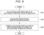
- Fig. 9 is a flowchart describing an example of processing of determining the discharge amount of ink from each nozzle 243 of the recording head 240 at the time of executing actual printing in the control portion 40 (driving condition determination portion 40c).
- the processing will be described focusing on one recording head 240 of the plurality of recording heads 240a to 240d of the head unit 24.
- control portion 40 converts print data received from an external apparatus (for example, a personal computer used by the user) into page image data in units of pages in accordance with print settings, and receives the page image data as one execution target job. Then, the control portion 40 calculates the discharge amount of ink of each nozzle 243 of the recording head 240 on the basis of the pixel value of the image data to be printed (step S201).
- an external apparatus for example, a personal computer used by the user
- the input image data input from the external computer to the image forming apparatus 1 is expressed in a raster format or a vector format, and in step S201, for example, the control portion 40 converts the input image data into image data of a pixel value (for example, gradation values of four colors: Y, M, C, and K) for each pixel region of a two-dimensional pixel matrix, and calculates the discharge amount of ink of each nozzle 243 using a preset pixel value/ink discharge amount conversion table (not illustrated).
- a pixel value for example, gradation values of four colors: Y, M, C, and K
- control portion 40 calculates the discharge amount of ink of each nozzle 243 of the recording head 240 such that at the overlapping portion, for example, both the nozzle 243 of the upstream recording head 240 and the nozzle 243 of the downstream recording head 240 are caused to discharge the ink and each dot of the image formed by the nozzles 243 of the overlapping portion is formed by overlapping the ink discharged from the nozzle 243 of the downstream recording head 240 on the ink discharged from the nozzle 243 of the upstream recording head 240.
- control portion 40 may change the ratio of the ink to be discharged from the nozzle 243 of the upstream recording head 240 and the ink to be discharged from the nozzle 243 of the downstream recording head 240 forming each dot stepwise from the center side toward the end portion side of the nozzle row.
- control portion 40 calculates driving conditions (for example, a piezoelectric drive voltage supplied to the image forming element of each nozzle 243) of each nozzle 243 of the recording head 240 from the ink discharge amount of each nozzle 243 of the recording head 240 using, for example, a preset ink discharge amount/drive voltage conversion table (not illustrated) (step S202).
- driving conditions for example, a piezoelectric drive voltage supplied to the image forming element of each nozzle 243
- control portion 40 corrects the piezoelectric drive voltage to be supplied to the image forming element of the end portion nozzle 243 of the recording head 240 using the drive voltage correction table data as illustrated in Fig. 7C on the basis of the discharge correction amount (that is, the discharge correction amounts ⁇ Lvc_U and ⁇ Lvc_D per discharge calculated in step S105) of the recording head 240 stored as the correction data 100d (step S203).
- the discharge correction amount that is, the discharge correction amounts ⁇ Lvc_U and ⁇ Lvc_D per discharge calculated in step S105
- control portion 40 performs such drive voltage adjustment processing on each of the four recording heads 240a to 240d of the head unit 24. At that time, the control portion 40 corrects the drive voltage using the correction data 100d set for each of the four recording heads 240a to 240d.
- the control portion 40 adjusts the discharge amount of ink of each nozzle 243 of each of the plurality of recording heads 240, and can form an image in which the streaky noise is suppressed on the recording medium P.
- the image forming apparatus 1 is configured such that, in consideration of the difference between the landing aspect of the ink discharged from the upstream recording head 240 and the landing aspect of the ink discharged from the downstream recording head 240, the discharge correction amounts ( ⁇ LvcU and ⁇ Lvc_D) per discharge are calculated from the central portion/end portion density difference ⁇ D with reference to the predetermined conversion table in which the first conversion table to be applied to the upstream recording head 240 and the second conversion table to be applied to the downstream recording head 240 are separately set.
- the image forming apparatus 1 can accurately adjust the density of the image formed by the nozzle 243 (that is, the end portion nozzle 243 in the nozzle row of the recording head 240) of the overlapping portion R of each of the plurality of recording heads 240a to 240d of the head unit 24.
- the streaky noise which would otherwise be formed on the recording medium P, can be unfailingly suppressed.
- the control portion 40 may correct the discharge amount of ink discharged from the end portion nozzle 243 of each of the plurality of recording heads 240 by changing the discharge gradation of the head (the number of times of discharge of ink discharge per pixel region (multi-drop method)) instead of or in addition to the correction of the piezoelectric drive voltage.
- processing in which the discharge gradation is corrected from two times to three times or from three times to four times may be performed, and in the case of decreasing the ink discharge amount, processing in which the discharge gradation is corrected from three times to two times or from four times to three times may be performed.
Landscapes
- Engineering & Computer Science (AREA)
- Physics & Mathematics (AREA)
- General Engineering & Computer Science (AREA)
- General Physics & Mathematics (AREA)
- Theoretical Computer Science (AREA)
- Quality & Reliability (AREA)
- Mathematical Physics (AREA)
- Ink Jet (AREA)
Abstract
Description
- The present invention relates to an image forming apparatus, a control method for the image forming apparatus, and a control program for the image forming apparatus.
- Conventionally, there is an inkjet type image forming apparatus that forms an image by discharging (ejecting) ink from a nozzle formed in a recording head and landing the ink on a recording medium such as paper while relatively moving the recording head and the recording medium.
- In this type of image forming apparatus, for the purpose of improving the recording speed, an apparatus configuration is adopted in which a plurality of recording heads each having a nozzle row formed therein is arranged in a staggered manner along a direction intersecting the direction of the relative movement described above (that is, along a width direction of the recording medium (hereinafter referred to as "width direction")) to configure a long line head, and an image is formed by the long line head. Such an image forming apparatus can form an image by causing the line head to scan the recording paper only once along a conveyance direction (also referred to as a one-pass method).
- Patent Literature 2:
JP 2008-294609 A - By the way, in this type of image forming apparatus, generally, the plurality of recording heads arranged in a staggered manner along the width direction is disposed such that adjacent recording heads overlap each other in the line head, and an overlapping portion in which discharge target regions overlap between other adjacent recording heads (hereinafter, simply referred to as an "overlapping portion") is formed at an end portion of the nozzle row of each recording head (see
Figs. 1 and3 ). -
Fig. 1 is a diagram illustrating an example of an arrangement aspect of two adjacent recording heads arranged in a line head and an example of a discharge aspect of ink discharged from each of the two adjacent recording heads. - Normally, at the overlapping portion, ink is discharged from both a nozzle of an upstream recording head (this means a recording head arranged on the upstream side in the conveyance direction in the line head. The same applies hereinafter) and a nozzle of a downstream recording head (this means a recording head arranged on the downstream side in the conveyance direction in the line head. The same applies hereinafter), and the density of an image at the overlapping portion is adjusted.
- Ideally, when pixel values of image data are the same, the amount of ink discharged from each recording head is the same, but, in actual use, the amount of ink discharged from each recording head has a slight difference between the recording heads due to individual differences among the recording heads and changes in the surrounding environment at that time. The slight difference between the recording heads causes a density difference between an image formed by the upstream recording head and an image formed by the downstream recording head.
- From such a viewpoint, in the image forming apparatus according to the conventional art, at the overlapping portion, the ink is discharged from both the nozzle of the upstream recording head and the nozzle of the downstream recording head, and further, the ratio of the ink discharged from the nozzle of the upstream recording head and the ink discharged from the nozzle of the downstream recording head is changed stepwise from a center side toward an end portion side of the nozzle row, so that a sudden density difference between the image formed by the upstream recording head and the image formed by the downstream recording head is prevented from occurring. That is, each dot of the image formed by the nozzles at the overlapping portion of the recording heads is formed such that the ink discharged from the nozzle of the downstream recording head overlaps the ink discharged from the nozzle of the upstream recording head.
- However, in this type of image forming apparatus, due to a manufacturing error, collision with another object in use, a difference in use environment between the time of manufacturing and the time of use, or the like, the positional relationship between the recording heads in the line head may slightly deviate in the width direction (that is, nozzle arrangement direction) from the designed positional relationship. In such a case, the total amount of ink discharged to the overlapping portion of the recording heads (that is, the total amount of ink discharged from the nozzle of the upstream recording head and ink discharged from the nozzle of the downstream recording head) deviates from the assumption, and in the image formed by the nozzles of the overlapping portion of the recording heads, a black streak may occur due to excessively large discharge dots, or a white streak may occur due to excessively small discharge dots (hereinafter, collectively referred to as "streaky noise").
- Note that
Fig. 1 illustrates a state in which the positional relationship between recording heads in a line head is deviated to the side of being close to each other in the width direction from the designed positional relationship, and a black streak occurs in an image region formed by the nozzles of the overlapping portion of the recording heads. In more detail,Fig. 1 illustrates a state where the ink discharge amount from each nozzle of the recording head is set on the assumption that only a dot Pu1 formed by the nozzle of the upstream recording head and a dot Pd1 formed by the nozzle of the downstream recording head overlap, but due to the positional deviation, the dot Pu1 formed by the nozzle of the upstream recording head, a dot Pd2 formed by the nozzle of the downstream recording head, and a dot Pu2 formed by the nozzle of the upstream recording head and the dot Pd1 formed by the nozzle of the downstream recording head overlap each other, and the dots become excessively large at the overlapping portions. - The present invention has been made in view of the problem described above, and an object is to provide an image forming apparatus, a control method for the image forming apparatus, and a control program for the image forming apparatus that enable appropriate adjustment of density of an image formed by nozzles of an overlapping portion of recording heads.
- To achieve the abovementioned object, according to an aspect of the present invention, an inkjet type image forming apparatus including a plurality of recording heads arranged in a staggered pattern, reflecting one aspect of the present invention comprises: a test print execution portion that forms a test image for density detection on a recording medium with the plurality of recording heads and reads density information of the test image formed on the recording medium; and a discharge correction amount setting portion that calculates, for each of the plurality of recording heads, a difference value between density of an image formed using an end portion nozzle of a nozzle row of the recording head and density of an image formed using a central nozzle of the nozzle row of the recording head from the read density information of the test image, and sets a discharge correction amount per discharge when causing ink to be discharged from the end portion nozzle at a time of executing actual printing on the basis of the difference value, wherein the discharge correction amount setting portion is configured to convert the difference value into the discharge correction amount with reference to a predetermined conversion table in which a first conversion table to be applied to a recording head on an upstream side in a conveyance direction among the plurality of recording heads and a second conversion table to be applied to a recording head on a downstream side in the conveyance direction among the plurality of recording heads are separately set.
- The advantages and features provided by one or more embodiments of the invention will become more fully understood from the detailed description given hereinbelow and the appended drawings which are given by way of illustration only, and thus are not intended as a definition of the limits of the present invention:
-
Fig. 1 is a diagram illustrating an example of an arrangement aspect of two adjacent recording heads arranged in a line head and an example of a discharge aspect of ink discharged from each of the two adjacent recording heads; -
Fig. 2 is a diagram illustrating a schematic configuration of an image forming apparatus according to an embodiment of the present invention; -
Fig. 3 is a schematic diagram illustrating a configuration of a head unit according to an embodiment of the present invention; -
Fig. 4 is a block diagram illustrating a main functional configuration of the image forming apparatus according to an embodiment of the present invention; -
Figs. 5A to 5C are diagrams describing an ink landing aspect (Fig. 5B ) when the density is corrected by a discharge amount Down of a nozzle of an overlapping portion of a downstream recording head and an ink landing aspect (Fig. 5C ) when the density is corrected by a discharge amount Down of a nozzle of an overlapping portion of an upstream recording head in a state where a black streak occurs in an image formed on a recording medium (Fig. 5A ); -
Fig. 6 is a diagram illustrating functional blocks of a control portion according to an embodiment of the present invention; -
Figs. 7A to 7C are diagrams describing an example of a method of correcting the ink discharge amount of the nozzle of the overlapping portion by a discharge correction amount setting portion according to an embodiment of the present invention; -
Fig. 8 is a flowchart describing an example of discharge correction amount calculation processing in a control portion (here, processing of test print execution portion and discharge correction amount setting portion) according to an embodiment of the present invention; and -
Fig. 9 is a flowchart describing an example of processing of determining the discharge amount of ink from each nozzle of a recording head at the time of executing actual printing in a control portion (here, processing of driving condition determination portion) according to an embodiment of the present invention. - Hereinafter, one or more embodiments of the present invention will be described with reference to the drawings. However, the scope of the invention is not limited to the disclosed embodiments. Note that, in the present specification and the drawings, components having substantially the same function are denoted by the same reference numerals, and redundant description is omitted.
- Hereinafter, an example of a configuration of an image forming apparatus (hereinafter, referred to as an "
image forming apparatus 1") according to an embodiment of the present invention will be described with reference toFigs. 2 to 4 . -
Fig. 2 is a diagram illustrating a schematic configuration of theimage forming apparatus 1. - The
image forming apparatus 1 is an inkjet type image forming apparatus that forms an image by discharging (ejecting) ink from a nozzle formed in a recording head and landing the ink on a recording medium P such as paper. Theimage forming apparatus 1 includes asheet feeding portion 10, animage forming portion 20, asheet ejection portion 30, and acontrol portion 40. - Under the control of the
control portion 40, theimage forming apparatus 1 conveys the recording medium P stored in thesheet feeding portion 10 to theimage forming portion 20, discharges ink on the recording medium P in theimage forming portion 20 to record an image, and conveys the recording medium P on which the image is recorded to thesheet ejection portion 30. - In detail, the
image forming apparatus 1 records a color image on the recording medium P by outputting and superimposing four colors: yellow (Y), magenta (M), cyan (C), and black (K) on the recording medium P at a predetermined number of recording gradations. Theimage forming apparatus 1 is configured to be capable of storing a color image on the recording medium P in the high-speed printing mode described above. Note that, hereinafter, ink colors of yellow (Y), magenta (M), cyan (C), and black (K) will be abbreviated respectively as Y, M, C, and K. - As the recording medium P, in addition to paper such as plain paper or coated paper, various media on which the ink landed on the surface can be fixed, such as of fabric or sheet-shaped resin, can be used.
- The
sheet feeding portion 10 includes asheet feeding tray 11 that stores the recording medium P, and amedium supply portion 12 that conveys and supplies the recording medium P from thesheet feeding tray 11 to theimage forming portion 20. Themedium supply portion 12 includes an annular belt whose inner side is supported by two rollers, and conveys the recording medium P from thesheet feeding tray 11 to theimage forming portion 20 by rotating the rollers in a state where the recording medium P is placed on the belt. - The
image forming portion 20 includes aconveyance portion 21, ahandover unit 22, aheating portion 23,head units 24, afixing portion 25, animage reading portion 26, and adelivery portion 27. - The
conveyance portion 21 holds the recording medium P placed on the conveyance surface of aconveyance drum 211 having a cylindrical shape, and conveys the recording medium P on theconveyance drum 211 in the conveyance direction along the conveyance surface by rotating and moving theconveyance drum 211 about a rotation axis (cylindrical axis) extending in a direction orthogonal to the conveyance direction (that is, in the width direction of the recording medium). - The
conveyance drum 211 includes a claw portion and an air intake portion, which are not illustrated, for holding the recording medium P on the conveyance surface. An end portion of the recording medium P is pressed by the claw portion, and is sucked to the conveyance surface by the air intake portion so as to be held on the conveyance surface. - The
handover unit 22 is provided at a position between themedium supply portion 12 of thesheet feeding portion 10 and theconveyance portion 21, holds and picks up one end of the recording medium P conveyed from themedium supply portion 12 with aswing arm portion 221, and hands over the recording medium P to theconveyance portion 21 via ahandover drum 222. - The
heating portion 23 is provided between the disposition position of thehandover drum 222 and the disposition position of thehead units 24, and heats the recording medium P so that the recording medium P conveyed by theconveyance portion 21 has a temperature within a predetermined temperature range. Theheating portion 23 includes, for example, an infrared heater or the like, and energizes the infrared heater on the basis of a control signal supplied from thecontrol portion 40 to cause the infrared heater to generate heat. - The
head units 24 record an image by discharging ink onto the recording medium P through a nozzle opening provided in an ink discharge surface facing the conveyance surface of theconveyance drum 211 at an appropriate timing according to the rotation of theconveyance drum 211 on which the recording medium P is held. - In the
head units 24, the ink discharge surface and the conveyance surface are disposed to be spaced apart a predetermined distance. In theimage forming apparatus 1 of the present embodiment, fourhead units 24 corresponding to the inks of four colors: Y, M, C, and K are arranged at predetermined intervals in the order of Y, M, C, and K colors from the upstream side in the conveyance direction of the recording medium P. Note that, since the fourhead units 24 according to the present embodiment have similar configurations, they are collectively referred to as the "head unit 24" below. - The
head unit 24 is used in position at the time of recording an image, and sequentially discharges the ink at predetermined intervals (conveyance direction intervals) at different positions in the conveyance direction according to the conveyance of the recording medium P, thereby recording an image by a single-pass method. -
Fig. 3 is a schematic diagram illustrating a configuration of thehead unit 24.Fig. 3 illustrates a surface of thehead unit 24 facing an outer peripheral surface of theconveyance drum 211. - Here, the
head unit 24 includes fourrecording heads 240a to 240d attached to anattachment member 244. In each of the fourrecording heads 240a to 240d, a plurality of image forming elements each including a pressure chamber (not illustrated) for storing ink, a piezoelectric element (not illustrated) provided on a wall surface of the pressure chamber, and anozzle 243 communicating with the pressure chamber is provided in a line along the width direction of the recording medium P. In this image forming element, when a drive signal for deforming and operating the piezoelectric element is input, the pressure chamber is deformed by the deformation of the piezoelectric element, the pressure in the pressure chamber changes, and the ink is discharged from thenozzle 243 communicating with the pressure chamber. Thus, in each of the fourrecording heads 240a to 240d, ink droplets of the liquid amount corresponding to the pixel value of the image data are discharged from thenozzle 243 toward the recording medium P, and an image is formed on the recording medium P carried on theconveyance drum 211. - The four
recording heads 240a to 240d are disposed in a staggered manner such that disposition ranges in the width direction of the recording medium P (nozzle row direction of recording heads 240) are connected without discontinuity. In addition, the fourrecording heads 240a to 240d are arranged such that, regarding a pair of recording heads 240 adjacent to each other, among the plurality of nozzles 243 (nozzle group) provided in each, the disposition ranges of a nozzle of one recording head 240 in the vicinity of an end portion on one side and a nozzle of the other recording head 240 in the vicinity of an end portion on the other side overlap each other in the nozzle row direction. That is, an overlapping portion R in which the discharge target regions overlap each other between adjacent other recording heads 240 is set at the end portion of the nozzle row of each recording head 240. - Note that, hereinafter, among the plurality of
recording heads 240a to 240d provided in thehead unit 24, the recording heads 240a and 240c arranged on the upstream side in the conveyance direction are referred to as "upstream recording heads 240", and the recording heads 240b and 240d arranged on the downstream side in the conveyance direction are referred to as "downstream recording heads 240". In addition, when they are not distinguished, they are simply referred to as the "recording head 240". In addition, a nozzle corresponding to the overlapping portion R within the nozzle row formed in each recording head 240 is also referred to as an "overlappingportion nozzle 243" or an "end portion nozzle 243", and a nozzle not corresponding to the overlapping portion R within the nozzle row formed in each recording head 240 is also referred to as a "central nozzle 243". - The disposition range of the
nozzles 243 included in thehead unit 24 in the width direction of the recording medium P covers the entire width in the width direction of the recording medium P in a region where an image is formed in the recording medium P conveyed by theconveyance drum 211, and thehead unit 24 is used by being fixed to the rotation shaft of theconveyance drum 211 at the time of forming the image. That is, thehead unit 24 constitutes a line head capable of discharging the ink over an image formable width in the width direction of the recording medium P with respect to the recording medium P. - The recording head 240 includes an ink heating portion (not illustrated) that heats the ink stored in the recording head 240, and discharges the heated and sol-like ink. When the sol-like ink is discharged onto the recording medium P, the ink is landed on the recording medium P and then naturally cooled, so that the ink quickly becomes gel-like and is solidified on the recording medium P.
- Note that as the ink discharged from the
nozzles 243 of the recording heads 240, for example, an ultraviolet-curable hot-melt ink composition can be used. - The fixing
portion 25 includes an energy ray emission portion disposed over the entire width in the width direction of the recording medium P in theconveyance portion 21, and irradiates the recording medium P placed on theconveyance portion 21 with an energy ray such as an ultraviolet ray from the energy ray emission portion to cure and fix the ink discharged on the recording medium P. The energy ray emission portion of the fixingportion 25 is disposed to face the conveyance surface between the disposition positions of thehead units 24 and the disposition position of ahandover drum 271 of thedelivery portion 27 in the conveyance direction. - The
image reading portion 26 is disposed facing the drum surface of theconveyance drum 211 on the downstream side in the conveyance direction of the position for fixing the image by the fixingportion 25. Theimage reading portion 26 reads the density of an image including a test image for density measurement, which will be described below, formed on the recording medium P conveyed by theconveyance drum 211. Theimage reading portion 26 sends data of the read image to thecontrol portion 40 as imaging data. - The
image reading portion 26 includes, for example, a combination of a light source that irradiates the recording medium P conveyed by theconveyance drum 211 with light and a sensor portion that detects the intensity of reflected light from the recording medium P on the basis of the light emitted from the light source to the recording medium P. The sensor portion is, for example, a line sensor in which a plurality of detection elements (pixels) is arranged in the width direction of the recording medium P. The sensor portion includes, for example, a charge coupled device (CCD) type imaging element, a complementary metal oxide semiconductor (CMOS) type imaging element, or the like, and can acquire a formed image on the recording medium P for each of a plurality of wavelength components, for example, at three wavelengths of red (R), green (G), and blue (B). - The
delivery portion 27 includes a belt loop 272 having an annular belt whose inner side is supported by two rollers, and thehandover drum 271 having a cylindrical shape that hands over the recording medium P from theconveyance portion 21 to the belt loop 272, and conveys the recording medium P handed over from theconveyance portion 21 onto the belt loop 272 by thehandover drum 271 with the belt loop 272 and sends the recording medium P to thesheet ejection portion 30. - The
sheet ejection portion 30 includes asheet ejection tray 31 having a plate shape on which the recording medium P sent from theimage forming portion 20 by thedelivery portion 27 is placed. Then, thesheet ejection portion 30 places the recording medium P on which an image is formed on thesheet ejection tray 31. -
Fig. 4 is a block diagram illustrating a main functional configuration of theimage forming apparatus 1. Theimage forming apparatus 1 includes thecontrol portion 40, ahead drive portion 50, aconveyance drive portion 60, animage processing portion 70, an input/output interface 80, and astorage portion 100. - The
control portion 40 includes a central processing unit (CPU) 41, random access memory (RAM) 42, and read only memory (ROM) 43, and integrally controls the entire operation of theimage forming apparatus 1. Thecontrol portion 40 receives image data transmitted from an external apparatus (for example, a personal computer) connected to a communication network such as a local area network (LAN) or a wide area network (WAN) via the input/output interface 80, and causes thehead drive portion 50, theconveyance drive portion 60, theimage processing portion 70, and the like to perform an operation of forming an image on the recording medium P on the basis of the image data (input image data). - The
CPU 41 reads various control programs and setting data stored in theROM 43, causes theRAM 42 to store them, and execute the programs to perform various arithmetic processing. - The
RAM 42 provides a working memory space for theCPU 41, and stores temporary data. TheRAM 42 may include, for example, nonvolatile memory. - The
ROM 43 stores various control programs executed by theCPU 41, setting data, and the like. Note that, instead of theROM 43, rewritable nonvolatile memory such as electrically erasable programmable read only memory (EEPROM) or flash memory may be used. - Each function (test
print execution portion 40a, discharge correctionamount setting portion 40b, and drivingcondition determination portion 40c (seeFig. 6 )) to be described below of thecontrol portion 40 is achieved, for example, by theCPU 41 referring to the control program and various data stored in theROM 43, theRAM 42, thestorage portion 100, and the like. However, some or all of the functions may be achieved by processing by a digital signal processor (DSP) or a dedicated hardware circuit (for example, ASIC or FPGA) instead of or in addition to the processing by theCPU 41. - The
head drive portion 50 supplies a drive signal corresponding to the image data to the image forming element of thehead unit 24 at an appropriate timing on the basis of control by thecontrol portion 40, and causes the nozzles of thehead unit 24 to discharge the ink of an amount corresponding to the pixel value of the image data. - The
head drive portion 50 receives image data subjected to image processing by thecontrol portion 40, and forms a predetermined image on the recording medium P on the basis of the image data. Specifically, under the control of thecontrol portion 40, thehead drive portion 50 applies, to thehead unit 24, a drive voltage (which means a piezoelectric drive voltage for driving the image forming element. The same applies hereinafter) according to the pixel value of the image data. Thus, the ink of a liquid amount corresponding to the pixel value of the image data is discharged (ejected) from thenozzle 243 of the recording head 240, and is landed at a predetermined position on the recording medium P to form an image. - The liquid amount of the ink discharged from the
nozzle 243 of the recording head 240 is basically adjusted on the basis of the voltage level of the drive voltage applied from thehead drive portion 50 to the individual image forming element of the recording head 240, but can also be adjusted by correcting the discharge gradation of theindividual nozzle 243 of the recording head 240 (the number of times of discharge for discharging per pixel region (multi-drop method)). - The
conveyance drive portion 60 supplies a drive signal to a conveyance drum motor provided in theconveyance drum 211 on the basis of the control signal supplied from thecontrol portion 40, and rotates theconveyance drum 211 at a predetermined speed and timing. In addition, theconveyance drive portion 60 supplies a drive signal to a motor for operating themedium supply portion 12, thehandover unit 22, and thedelivery portion 27 on the basis of the control signal supplied from thecontrol portion 40, and causes the recording medium P to be supplied to theconveyance portion 21 and discharged from theconveyance portion 21. - The
image processing portion 70 performs predetermined image processing on the image data stored in thestorage portion 100, and causes thestorage portion 100 to store the obtained image data. This image processing includes color conversion processing, gradation correction processing, pseudo halftone processing, and the like in addition to correction processing of correcting image data by applying a correction table or the like, which is not illustrated, to the image data. - The input/
output interface 80 is connected to an input/output interface of an external apparatus (for example, a personal computer), and mediates transmission and reception of data between thecontrol portion 40 and the external apparatus. The input/output interface 80 includes, for example, any one of various serial interfaces and various parallel interfaces, or a combination thereof. - The
storage portion 100 stores printjob data 100a,test image data 100b,conversion table data 100c,correction data 100d, and the like. As thestorage portion 100, for example, a hard disk drive (HDD), dynamic random access memory (DRAM), or the like is used. - The
print job data 100a is data input from the external apparatus via the input/output interface 80, and includes, for example, job identification information, image data to be printed, setting data related to image recording, status data related to a status (for example, the number of sheets on which printing is completed) during execution of a print job, and the like. - The
test image data 100b is image data of a test image for density measurement. Thetest image data 100b is referred to at the time of test printing, for example, and is set so that a predetermined amount of ink is discharged from all thenozzles 243 of the fourrecording heads 240a to 240d, and for example, a solid image with a predetermined gradation is used. - The
conversion table data 100c is table data for the control portion 40 (discharge correction amount setting portion 41) to be described below to calculate the discharge correction amount of the ink of thenozzle 243 of the overlapping portion R from the read information of the test image on the recording medium P formed by the test printing (seeFigs. 7A and 7B to be described below). - The
correction data 100d is data related to the discharge correction amount of the ink of thenozzle 243 of the overlapping portion R calculated using theconversion table data 100c. Thecorrection data 100d separately stores, for example, data to be applied to each of the plurality ofrecording heads 240a to 240d. Thecorrection data 100d is prepared to correct the ink discharge amount of each of the plurality ofrecording heads 240a to 240d determined by thecontrol portion 40 on the basis of the pixel value of the image data to be printed at the time of performing the actual printing. That is, at the time of the actual printing, the discharge amount of the ink from the nozzle of the overlapping portion R of the plurality ofrecording heads 240a to 240d is adjusted to the discharge amount in which the streaky noise does not occur in the image by thecorrection data 100d. - Hereinafter, a detailed configuration of the
control portion 40 according to the present embodiment will be described with reference toFigs. 5A to 10. - First, a basic concept of density correction processing performed by the
image forming apparatus 1 according to the present embodiment will be described. - In order to suppress the above-described streaky noise caused by the positional deviation of the recording heads 240, the applicant of the present application has proposed a method of forming a test image on the recording medium P by test printing and performing feedback from the density of the image formed on the recording medium P to the discharge amount of the
nozzles 243 inJP 2008-294609 A - However, as a result of intensive studies by the inventors of the present application, by the method described in
JP 2008-294609 A JP 2008-294609 A - Note that such a problem particularly noticeably appears when a gel-like ink the spread of ink of which is small when the ink discharged from the nozzle lands is used.
-
Figs. 5A to 5C are diagrams describing an ink landing aspect (Fig. 5B ) when the density is corrected by the discharge amount Down of thenozzle 243 of the overlapping portion R of the downstream recording head 240 and an ink landing aspect (Fig. 5C ) when the density is corrected by the discharge amount Down of thenozzle 243 of the overlapping portion R of the upstream recording head 240 in a state where a black streak occurs in an image formed on the recording medium P (Fig. 5A ). - Note that
Fig. 5A illustrates a state where the ink discharge amount from eachnozzle 243 of the recording head 240 is set on the assumption that only a dot A1 formed by thenozzle 243 of the upstream recording head 240 and adot B 1 formed by thenozzle 243 of the downstream recording head 240 overlap, but due to the positional deviation, dots A1 and A2 formed by thenozzle 243 of the upstream recording head 240 and dots B 1 and B2 formed by thenozzle 243 of the downstream recording head 240 are in a state of overlapping each other, and the dots become excessively large at the overlapping portions R. - In the correction method of
JP 2008-294609 A end portion nozzle 243 of the recording head 240) on the recording medium P and the density of an image formed by a nozzle (that is, thecentral nozzle 243 of the recording head 240) of a portion other than the overlapping portion R on the recording medium P are detected. Then, a state in which a black streak occurs or a state in which a white streak occurs in an image formed on the recording medium P is detected on the basis of a difference value between these densities. Then, in the correction method ofJP 2008-294609 A nozzle 243 of the overlapping portion R, and in addition, in a case where it is detected that a white streak occurs in the image formed on the recording medium P, it is attempted to eliminate the white streak in the image by increasing the discharge amount per pixel by the nozzle of the overlapping portion R. - However, in the correction method of
JP 2008-294609 A nozzle 243 to be corrected for the ink discharge amount exists in the upstream recording head 240 in thehead unit 24 or in the downstream recording head 240 in thehead unit 24. - However, in practice, a difference occurs in the density change amount between the case where the density is corrected by the discharge amount Down (discharge amount Up in case of white streak) of the
nozzle 243 of the overlapping portion R of the downstream recording head 240 and the case where the density is corrected by the discharge amount Down (discharge amount Up in case of white streak) of thenozzle 243 of the overlapping portion R of the upstream recording head 240. Therefore, in the correction method ofJP 2008-294609 A - Here, as illustrated in
Fig. 5A , a state in which a black streak occurs in an image formed on the recording medium P is considered. Note that, in this case, in order to eliminate the black streak, it is necessary to perform correction to reduce the discharge amount of the ink discharged from thenozzle 243 of the overlapping portion R in order to reduce the density of the image formed by thenozzle 243 of the overlapping portion R. - First, when the ink is discharged from the upstream recording head 240, the ink lands on a flat recording medium P, and forms dots A1, A2, and the like at pixel positions of the recording medium P. Next, when the ink is discharged from the downstream recording head 240, the ink lands so as to overlap the previously formed dots A1 and A2 in the overlapping portion R, and forms
dots B 1 and B2 spreading around the dots A1 and A2 to fill the paper surface. - At this time, when the density is corrected only by the discharge amount Down of the
nozzle 243 of the overlapping portion R of the downstream recording head 240, as illustrated inFig. 5B , since there is no change in the sizes of the dots A1 and A2 formed by the ink discharged from the upstream recording head 240, thedots B 1 and B2 of the ink discharged from the downstream recording head 240 are largely spread even after the correction, and the dot diameter of the combined dots of the dot A2 and the dot B 1 (and the combined dot of the dot A1 and the dot B2) remains large. Since the density of the image typically depends on the dot diameter, in this case, the density change amount of the image formed by thenozzle 243 of the overlapping portion R is smaller than the case where the density is corrected by the discharge amount Down of thenozzle 243 of the overlapping portion R of the upstream recording head 240. Therefore, a black streak may remain in the image even after the correction. In other words, in order to reduce the density of the image, it is necessary to reduce the sizes of the dots A1 and A2 formed by the ink discharged from the upstream recording head 240 to some extent or less. - On the other hand, when the density is corrected only by the discharge amount Down of the
nozzle 243 of the overlapping portion R of the upstream recording head 240, there is a case where the dots A1 and A2 formed by the ink discharged from the upstream recording head 240 are in a state of being isolated as illustrated inFig. 5C . In this case, even when the ink discharged from the downstream recording head 240 overlaps the dots A1 and A2, the dot diameter of the combined dot of the dot A2 and the dot B 1 (or the combined dot of the dot A1 and the dot B2) becomes too small, or the combined dot is disposed at a biased position in the pixel region of the recording medium P, and as a result, a white streak may occur in the image. - In other words, this means that the effect on the image by the discharge amount Down of the
nozzle 243 of the overlapping portion R of the downstream recording head 240 and the effect on the image by the discharge amount Down of thenozzle 243 of the overlapping portion R of the upstream recording head 240 are different, and the density of the image cannot be appropriately adjusted even when only one of them is corrected. Further, in a case where the discharge amount Down of the nozzle of the overlapping portion R of the downstream recording head 240 and the discharge amount Down of the nozzle of the overlapping portion R of the upstream recording head 240 are the same amount (that is, the correction amounts are the same), depending on the magnitude of the correction amount, a state in which the dots A1 and A2 formed by the ink discharged from the upstream recording head 240 are isolated occurs, or the dot diameter of the combined dot of the dot A2 and the dot B 1 (and the combined dot of the dot A1 and the dot B2) remains large, and there is a possibility that the density of the image cannot be set to a desired value. - In the invention of the present application, from such a viewpoint, when a black streak occurs in an image formed on the recording medium P, both the discharge amount Down of the
nozzle 243 of the overlapping portion R of the downstream recording head 240 and the discharge amount Down of thenozzle 243 of the overlapping portion R of the upstream recording head 240 are performed to correct the image density. Then, at this time, the correction amount (here, the correction in the Down direction) of the discharge amount of thenozzle 243 of the overlapping portion R of the downstream recording head 240 is set to be larger than the correction amount (here, the correction in the Down direction) of the discharge amount of the nozzle of the overlapping portion R of the upstream recording head 240. - This makes it possible to adjust the dot diameter of the discharge dot to a suitable size while avoiding the isolated state of the discharge dot immediately under the overlapping portion R. That is, thus, the occurrence of a black streak can be more unfailingly suppressed.
- Note that, here, a density correction method in a case where a black streak occurs in an image formed on the recording medium P in the
image forming apparatus 1 according to the present embodiment has been described, but a similar concept can be applied to a density correction method in a case where a white streak occurs in an image formed on the recording medium P. - That is, when a white streak occurs in an image formed on the recording medium P, in order to eliminate the white streak, it is necessary to perform correction to increase the discharge amount of the ink discharged from the
nozzle 243 of the overlapping portion R in order to increase the density of the image formed by thenozzle 243 of the overlapping portion R. - At this time, when the dots A1 and A2 formed by the ink discharged from the upstream recording head 240 remain in an isolated state, or when the size of the dots A1 and A2 becomes too large, the density of the image cannot be appropriately adjusted. Then, at this time, in a case where the discharge amount Up of the nozzle of the overlapping portion R of the downstream recording head and the discharge amount Up of the nozzle of the overlapping portion R of the upstream recording head 240 are the same amount (that is, the correction amounts are the same), depending on the magnitude of the correction amount, the dots A1 and A2 formed by the ink discharged from the upstream recording head remain in an isolated state, or the dot diameter of the combined dot of the dot A2 and the dot B 1 (and the combined dot of the dot A1 and the dot B2) becomes excessively large, and there is a possibility that the density of the image cannot be set to a desired value.
- In the invention of the present application, from such a viewpoint, when a white streak occurs in an image formed on the recording medium P, both the discharge amount Up of the
nozzle 243 of the overlapping portion R of the downstream recording head 240 and the discharge amount Up of the nozzle of the overlapping portion R of the upstream recording head 240 are performed to correct the image density. Then, at this time, the correction amount (here, the correction in the Up direction) of the discharge amount of thenozzle 243 of the overlapping portion R of the downstream recording head 240 is set to be smaller than the correction amount (here, the correction in the Up direction) of the discharge amount of thenozzle 243 of the overlapping portion R of the upstream recording head 240. -
Fig. 6 is a diagram illustrating an example of functional blocks of thecontrol portion 40. - The
control portion 40 includes the testprint execution portion 40a, the discharge correctionamount setting portion 40b, and the drivingcondition determination portion 40c. - Here, the test
print execution portion 40a is a functional unit that forms a test image for density detection on the recording medium P using thehead unit 24 and causes theimage reading portion 26 to read density information of the test image formed on the recording medium P. - The discharge correction
amount setting portion 40b is a functional unit that calculates, at the time of test printing, for each of the plurality of recording heads 240 (here, fourrecording heads 240a to 240d), a difference value between the density of the image formed using theend portion nozzle 243 corresponding to the overlapping portion R in the nozzle row in the recording head 240 and the density of the image formed using thecentral nozzle 243 not corresponding to the overlapping portion R in the nozzle row in the recording head 240 from the density information of the read test image, and sets the discharge correction amount per discharge at the time of discharging the ink from theend portion nozzle 243 at the time of actual printing on the basis of the difference value. - The discharge correction
amount setting portion 40b is configured to convert the difference value into the discharge correction amount with reference to a predetermined conversion table (Fig. 7B described below). Here, the predetermined conversion table includes a first conversion table applied to the upstream recording head 240 (hereinafter, referred to as a "first conversion table") and a second conversion table applied to the downstream recording head 240 (hereinafter, referred to as a "second conversion table"), and the two different tables are prepared. Then, the discharge correctionamount setting portion 40b is configured to refer to the first conversion table when calculating the discharge correction amount to be applied to theend portion nozzle 243 of the upstream recording head 240 and refer to the second conversion table when calculating the discharge correction amount to be applied to theend portion nozzle 243 of the downstream recording head 240. - At the time of executing the actual printing, the driving
condition determination portion 40c calculates the discharge amount of ink by eachnozzle 243 of the nozzle row of each of the plurality of recording heads 240 (here, fourrecording heads 240a to 240d) on the basis of the pixel value of the image data to be printed, and determines the driving condition (for example, a piezoelectric drive voltage applied to individual image forming element) of each of the plurality of recording heads 240. - At this time, the driving
condition determination portion 40c corrects the driving condition (for example, a piezoelectric drive voltage applied to individual image forming element) of each of the plurality of recording heads 240 on the basis of the discharge correction amount set for each of the plurality of recording heads 240, and adjusts the discharge amount of the ink by theend portion nozzle 243 of each of the plurality of recording heads 240. - Note that the driving
condition determination portion 40c determines the driving condition of each recording head 240 such that, at the overlapping portion, for example, both thenozzle 243 of the upstream recording head 240 and thenozzle 243 of the downstream recording head 240 are caused to discharge the ink and each dot of the image formed by thenozzles 243 of the overlapping portion is formed by overlapping the ink discharged from thenozzle 243 of the downstream recording head 240 on the ink discharged from thenozzle 243 of the upstream recording head 240. -
Figs. 7A to 7C are diagrams describing an example of a method of correcting the ink discharge amount of thenozzle 243 of the overlapping portion R by the discharge correctionamount setting portion 40b. Note thatFigs. 7A, 7B, and 7C are examples of table data referred to by the discharge correctionamount setting portion 40b at the time of correction. InFigs. 7A, 7B, and 7C , for convenience of description, only table data referred to in a case where the density of the image region formed by theend portion nozzle 243 of the recording head 240 is higher than the density of the image region formed by thecentral nozzle 243 of the recording head 240 (that is, a state where a black streak occurs in the image) is illustrated. -
Fig. 7A is a diagram illustrating an example of table data (hereinafter, referred to as "density correction value calculation table data") for calculating a density correction value ΔDc of theend portion nozzle 243 from a difference value ΔD (hereinafter referred to as "central portion/end portion density difference ΔD") between the density of an image formed using the end portion nozzle (that is, the nozzle corresponding to the overlapping portion R in the nozzle row of the recording head 240) 243 of the recording head 240 and the density of an image formed using the central nozzle (that is, the nozzle corresponding to a portion other than the overlapping portion R in the nozzle row of the recording head 240) 243 of the recording head 240. - Note that, in the present embodiment, from the viewpoint of fine adjustment, the central portion/end portion density difference ΔD and the density correction value ΔDc are set to different values, but the central portion/end portion density difference ΔD and the density correction value ΔDc may be set to the same value. In this case, the density correction value calculation table data is unnecessary.
-
Fig. 7B is a diagram illustrating an example of table data (hereinafter, referred to as "discharge correction amount calculation table data") for calculating discharge correction amount ΔLvcU (discharge correction amount applied to the upstream recording head 240) and ΔLvc_D (discharge correction amount applied to the downstream recording head 240) per discharge by theend portion nozzle 243 from the density correction value ΔDc of theend portion nozzle 243. - In the discharge correction amount calculation table data, for example, when the density correction value ΔDc is on the positive side (that is, when the density of the image formed using the
end portion nozzle 243 is higher than the density of the image formed using the central nozzle 243), the discharge correction amounts ΔLvc_U and ΔLvc_D are set in the direction of decreasing the discharge amount of ink by theend portion nozzle 243. In addition, when the density correction value ΔDc is on the negative side (that is, when the density of the image formed using theend portion nozzle 243 is lower than the density of the image formed using the central nozzle 243), the discharge correction amounts ΔLvc_U and ΔLvc_D are set in the direction of increasing the discharge amount of ink by theend portion nozzle 243. - In addition, as the discharge correction amount calculation table data, different table data is prepared: table data (first conversion table) (solid line in
Fig. 7B ) applied to the upstream recording head 240 and table data (second conversion table) (dotted line inFig. 7B ) applied to the downstream recording head 240. More specifically, in the region where a black streak is eliminated in the image, the discharge correction amount (that is, the discharge correction amount per unit amount of the central portion/end portion density difference ΔD) ΔLvc_U per unit amount of the density correction value ΔDc of the first conversion table is set to be smaller than the discharge correction amount (that is, the discharge correction amount per unit amount of the central portion/end portion density difference ΔD) ΔLvc_D per unit amount of the density correction value ΔDc of the second conversion table. In addition, in the region where a white streak is eliminated in the image, the discharge correction amount (that is, the discharge correction amount per unit amount of the central portion/end portion density difference ΔD) ΔLvc_U per unit amount of the density correction value ΔDc of the first conversion table is set to be larger than the discharge correction amount (that is, the discharge correction amount per unit amount of the central portion/end portion density difference ΔD) ΔLvc D per unit amount of the density correction value ΔDc of the second conversion table. - Note that a function (that is, graph characteristics) set in the density correction value calculation table data and a function (that is, graph characteristics) set in the discharge correction amount calculation table data change according to the viscosity characteristic of the gel-like ink, the distance in the conveyance direction between the upstream recording head 240 and the downstream recording head 240, the ink discharge characteristic of the recording head 240 itself, the time from when the ink is discharged by the recording head 240 to when the fixing processing is performed by the fixing
portion 25, and the like. Therefore, these pieces of data are set in advance for each type of theimage forming apparatus 1 using experimental data and simulation. -
Fig. 7C is a diagram illustrating an example of table data (hereinafter, referred to as "drive voltage correction table data") for calculating the correction amount of the piezoelectric drive voltage of theend portion nozzle 243 from the discharge correction amounts ΔLvc_U and ΔLvc_D per discharge by theend portion nozzle 243. Note that as the drive voltage correction table data, the same table data is applied to both the case of application to the discharge correction amount ΔLvc_U and the case of application to the discharge correction amount ΔLvc_D. -
Fig. 8 is a flowchart describing an example of discharge correction amount calculation processing in the control portion 40 (here, processing of the testprint execution portion 40a and the discharge correctionamount setting portion 40b). - When setting the ink discharge correction amount at the overlapping portion R, the
control portion 40 first refers to testimage data 100a stored in thestorage portion 100, and forms a test image for density detection on the recording medium P using thehead unit 24 as test printing (step S 101). For example, at the time of test printing, thecontrol portion 40 causes all thenozzles 243 of the four recording heads 240 to discharge a predetermined amount of ink according to thetest image data 100a. - Next, the
control portion 40 causes theimage reading portion 26 to read density information of the test image formed on the recording medium P (step S102). - Next, the
control portion 40 calculates a difference value (central portion/end portion density difference ΔD) between the density of the image formed using theend portion nozzle 243 corresponding to the overlapping portion R in the nozzle row of the recording head 240 and the density of the image formed using thecentral nozzle 243 not corresponding to the overlapping portion R in the nozzle row of the recording head 240 from the density information of the test image formed on the recording medium P read by the image reading portion 26 (step S103). - Next, the
control portion 40 calculates a density correction amount ΔDc of the image formed using theend portion nozzle 243 of the recording head 240 from the central portion/end portion density difference ΔD calculated in step S103 with reference to the density correction value calculation table data as illustrated inFig. 7A (step S104). - Note that, in steps S 103 and S104, the
control portion 40 calculates the central portion/end portion density difference ΔD (that is, the density correction amount ΔDc) for the image region formed by each of the fourrecording heads 240a to 240d. This is because the density of each of the image region formed using thenozzles 243 of the overlapping portion R between therecording head 240a and therecording head 240b, the image region formed using thenozzles 243 of the overlapping portion R between therecording head 240b and therecording head 240c, and the image region formed using thenozzles 243 of the overlapping portion R between therecording head 240c and therecording head 240d often differs depending on the deviation aspect of the positional relationship between therecording heads 240a to 240d in thehead unit 24. - Next, the
control portion 40 calculates the discharge correction amounts ΔLvc_U and ΔLvc_D of the ink of theend portion nozzle 243 for each of the plurality of recording heads 240 with reference to the discharge correction amount calculation table data as illustrated inFig. 7B from the density correction amount ΔDc calculated in step S 104 (step S105). - In step S105, the
control portion 40 calculates the discharge correction amount ΔLvc_U of the ink of theend portion nozzle 243 by applying the first conversion table of the discharge correction amount calculation table data with regard to the upstream recording head 240, and calculates the discharge correction amount ΔLvc_D of the ink of theend portion nozzle 243 by applying the second conversion table of the discharge correction amount calculation table data with regard to the downstream recording head 240. - Note that, in step S105, the
control portion 40 calculates the discharge correction amount (ΔLvc_U or ΔLvc_D) of the ink of theend portion nozzle 243 for each of the plurality of recording heads 240 from the density correction amount ΔDc calculated for each of the plurality of recording heads 240 (here, fourrecording heads 240a to 240d). Then, thecontrol portion 40 stores the discharge correction amounts ΔLvc_U and ΔLvc_D calculated for each of the plurality of recording heads 240 (here, fourrecording heads 240a to 240d) in thestorage portion 100 ascorrection data 100d. - Through such a series of processing, the
control portion 40 can set the discharge correction amounts ΔLvc_U and ΔLvc_D for each of the plurality of recording heads 240 (here, fourrecording heads 240a to 240d). - In this flow, when a black streak occurs in an image formed on the recording medium P, the
control portion 40 performs correction setting to adjust the image density by performing both the discharge amount Down of thenozzle 243 of the overlapping portion R of the downstream recording head 240 and the discharge amount Down of thenozzle 243 of the overlapping portion R of the upstream recording head 240. In addition, when a white streak occurs in an image formed on the recording medium P, thecontrol portion 40 performs correction setting to adjust the image density by performing both the discharge amount Up of thenozzle 243 of the overlapping portion R of the downstream recording head 240 and the discharge amount Up of thenozzle 243 of the overlapping portion R of the upstream recording head 240. - Then, in a case where a black streak occurs in the image formed on the recording medium P, the
control portion 40 calculates the discharge correction amount so that the correction amount (here, the correction in the Down direction) ΔLvc D of the discharge amount of thenozzle 243 of the overlapping portion R of the downstream recording head 240 is set to be larger than the correction amount (here, the correction in the Down direction) ΔLvc_U of the discharge amount of the nozzle of the overlapping portion R of the upstream recording head 240. In addition, in a case where a white streak occurs in the image formed on the recording medium P, thecontrol portion 40 calculates the discharge correction amount so that the correction amount (here, the correction in the Up direction) ΔLvc_D of the discharge amount of thenozzle 243 of the overlapping portion R of the downstream recording head 240 is set to be smaller than the correction amount (here, the correction in the Up direction) ΔLvc_U of the discharge amount of the nozzle of the overlapping portion R of the upstream recording head 240. - This makes it possible to more accurately set the discharge correction amount as compared with the correction processing of the image forming apparatus according to the conventional art, and thus, it is possible to more unfailingly suppress the streaky noise.
- Next, processing in which the control portion 40 (driving
condition determination portion 40c) determines the driving condition of the recording head 240 at the time of executing the actual printing will be described. -
Fig. 9 is a flowchart describing an example of processing of determining the discharge amount of ink from eachnozzle 243 of the recording head 240 at the time of executing actual printing in the control portion 40 (drivingcondition determination portion 40c). Here, the processing will be described focusing on one recording head 240 of the plurality ofrecording heads 240a to 240d of thehead unit 24. - First, the
control portion 40 converts print data received from an external apparatus (for example, a personal computer used by the user) into page image data in units of pages in accordance with print settings, and receives the page image data as one execution target job. Then, thecontrol portion 40 calculates the discharge amount of ink of eachnozzle 243 of the recording head 240 on the basis of the pixel value of the image data to be printed (step S201). - The input image data input from the external computer to the
image forming apparatus 1 is expressed in a raster format or a vector format, and in step S201, for example, thecontrol portion 40 converts the input image data into image data of a pixel value (for example, gradation values of four colors: Y, M, C, and K) for each pixel region of a two-dimensional pixel matrix, and calculates the discharge amount of ink of eachnozzle 243 using a preset pixel value/ink discharge amount conversion table (not illustrated). - Note that the
control portion 40 calculates the discharge amount of ink of eachnozzle 243 of the recording head 240 such that at the overlapping portion, for example, both thenozzle 243 of the upstream recording head 240 and thenozzle 243 of the downstream recording head 240 are caused to discharge the ink and each dot of the image formed by thenozzles 243 of the overlapping portion is formed by overlapping the ink discharged from thenozzle 243 of the downstream recording head 240 on the ink discharged from thenozzle 243 of the upstream recording head 240. At this time, thecontrol portion 40 may change the ratio of the ink to be discharged from thenozzle 243 of the upstream recording head 240 and the ink to be discharged from thenozzle 243 of the downstream recording head 240 forming each dot stepwise from the center side toward the end portion side of the nozzle row. - Next, the
control portion 40 calculates driving conditions (for example, a piezoelectric drive voltage supplied to the image forming element of each nozzle 243) of eachnozzle 243 of the recording head 240 from the ink discharge amount of eachnozzle 243 of the recording head 240 using, for example, a preset ink discharge amount/drive voltage conversion table (not illustrated) (step S202). - Next, the
control portion 40 corrects the piezoelectric drive voltage to be supplied to the image forming element of theend portion nozzle 243 of the recording head 240 using the drive voltage correction table data as illustrated inFig. 7C on the basis of the discharge correction amount (that is, the discharge correction amounts ΔLvc_U and ΔLvc_D per discharge calculated in step S105) of the recording head 240 stored as thecorrection data 100d (step S203). - Note that the
control portion 40 performs such drive voltage adjustment processing on each of the fourrecording heads 240a to 240d of thehead unit 24. At that time, thecontrol portion 40 corrects the drive voltage using thecorrection data 100d set for each of the fourrecording heads 240a to 240d. - According to the flow as described above, at the time of executing the actual printing, the
control portion 40 adjusts the discharge amount of ink of eachnozzle 243 of each of the plurality of recording heads 240, and can form an image in which the streaky noise is suppressed on the recording medium P. - As described above, the
image forming apparatus 1 according to the present embodiment is configured such that, in consideration of the difference between the landing aspect of the ink discharged from the upstream recording head 240 and the landing aspect of the ink discharged from the downstream recording head 240, the discharge correction amounts (ΔLvcU and ΔLvc_D) per discharge are calculated from the central portion/end portion density difference ΔD with reference to the predetermined conversion table in which the first conversion table to be applied to the upstream recording head 240 and the second conversion table to be applied to the downstream recording head 240 are separately set. - Accordingly, the
image forming apparatus 1 according to the present embodiment can accurately adjust the density of the image formed by the nozzle 243 (that is, theend portion nozzle 243 in the nozzle row of the recording head 240) of the overlapping portion R of each of the plurality ofrecording heads 240a to 240d of thehead unit 24. Thus, the streaky noise, which would otherwise be formed on the recording medium P, can be unfailingly suppressed. - In the embodiment described above, as an example of the configuration of the
control portion 40, the aspect has been indicated in which the discharge amount of ink discharged from theend portion nozzle 243 of the recording head 240 is corrected by correcting the piezoelectric drive voltage at the time of the actual printing. However, thecontrol portion 40 may correct the discharge amount of ink discharged from theend portion nozzle 243 of each of the plurality of recording heads 240 by changing the discharge gradation of the head (the number of times of discharge of ink discharge per pixel region (multi-drop method)) instead of or in addition to the correction of the piezoelectric drive voltage. - For example, in the case of increasing the ink discharge amount, processing in which the discharge gradation is corrected from two times to three times or from three times to four times may be performed, and in the case of decreasing the ink discharge amount, processing in which the discharge gradation is corrected from three times to two times or from four times to three times may be performed.
- With the image forming apparatus according to an embodiment of the present invention, it is possible to appropriately adjust the density of an image formed by nozzles of an overlapping portion of recording heads.
- Although embodiments of the present invention have been described and illustrated in detail, the disclosed embodiments are made for purposes of illustration and example only and not limitation. The scope of the present invention should be interpreted by terms of the appended claims. The technique described in the claims includes various modifications and changes of the specific examples exemplified above.
Claims (9)
- An inkjet type image forming apparatus (1) including a plurality of recording heads (240) arranged in a staggered pattern, the image forming apparatus (1) comprising:a test print execution portion (40a) that forms a test image for density detection on a recording medium (P) with the plurality of recording heads (240) and reads density information of the test image formed on the recording medium (P); anda discharge correction amount setting portion (40b) that calculates, for each of the plurality of recording heads (240), a difference value between density of an image formed using an end portion nozzle (243) of a nozzle row of the recording head (240) and density of an image formed using a central nozzle (243) of the nozzle row of the recording head (240) from the read density information of the test image, and sets a discharge correction amount per discharge when causing ink to be discharged from the end portion nozzle (243) at a time of executing actual printing on the basis of the difference value, whereinthe discharge correction amount setting portion (40b) is configured to convert the difference value into the discharge correction amount with reference to a predetermined conversion table in which a first conversion table to be applied to a recording head (240) on an upstream side in a conveyance direction among the plurality of recording heads (240) and a second conversion table to be applied to a recording head (240) on a downstream side in the conveyance direction among the plurality of recording heads (240) are separately set.
- The image forming apparatus (1) according to claim 1, whereinthe first and second conversion tablesin a case of a first aspect in which the density of the image formed using the end portion nozzle (243) in the test image is higher than the density of the image formed using the central nozzle (243), converts the difference value into the discharge correction amount in a direction of decreasing the discharge amount of the ink of the end portion nozzle (243), andin a case of a second aspect in which the density of the image formed using the end portion nozzle (243) in the test image is lower than the density of the image formed using the central nozzle (243), converts the difference value into the discharge correction amount in a direction of increasing the discharge amount of the ink of the end portion nozzle (243).
- The image forming apparatus (1) according to claim 2, whereinin the first aspect,the discharge correction amount per unit amount of the difference value of the first conversion table is set to be smaller than the discharge correction amount per unit amount of the difference value of the second conversion table, andin the second aspect,the discharge correction amount per unit amount of the difference value of the first conversion table is set to be larger than the discharge correction amount per unit amount of the difference value of the second conversion table.
- The image forming apparatus (1) according to claim 1, wherein
the discharge correction amount setting portion (40b) corrects the discharge amount of the ink discharged from the end portion nozzle (243) of each of the plurality of recording heads (240) by changing a piezoelectric drive voltage supplied to an image forming element of the end portion nozzle (243) of each of the plurality of recording heads (240). - The image forming apparatus (1) according to claim 1, wherein
the discharge correction amount setting portion (40b) corrects the discharge amount of the ink discharged from the end portion nozzle (243) of each of the plurality of recording heads (240) by changing a discharge gradation of the end portion nozzle (243) of each of the plurality of recording heads (240). - The image forming apparatus (1) according to claim 1, comprising:a driving condition determination portion (40c) that calculates a discharge amount of ink of each nozzle of each of the plurality of recording heads (240) on the basis of a pixel value of image data to be printed and determines a driving condition of each of the plurality of recording heads (240) at the time of executing the actual printing, whereinthe driving condition determination portion (40c) corrects the driving condition of each of the plurality of recording heads (240) on the basis of the discharge correction amount set for each of the plurality of recording heads (240).
- The image forming apparatus (1) according to claim 1, wherein the ink is a gel-like ink.
- A control method for an inkjet type image forming apparatus (1) including a plurality of recording heads (240) arranged in a staggered pattern, the method comprising:first processing of forming a test image for density detection on a recording medium (P) with the plurality of recording heads (240) and reading density information of the test image formed on the recording medium (P); andsecond processing of calculating, for each of the plurality of recording heads (240), a difference value between density of an image formed using an end portion nozzle (243) of a nozzle row of the recording head (240) and density of an image formed using a central nozzle (243) of the nozzle row of the recording head (240) from the read density information of the test image, and setting a discharge correction amount per discharge when causing ink to be discharged from the end portion nozzle (243) at a time of executing actual printing on the basis of the difference value, whereinthe second processing is configured to convert the difference value into the discharge correction amount with reference to a predetermined conversion table in which a first conversion table to be applied to a recording head (240) on an upstream side in a conveyance direction among the plurality of recording heads (240) and a second conversion table to be applied to a recording head (240) on a downstream side in the conveyance direction among the plurality of recording heads (240) are separately set.
- A control program for an inkjet type image forming apparatus (1) including a plurality of recording heads (240) arranged in a staggered pattern, the program comprising:first processing of forming a test image for density detection on a recording medium (P) with the plurality of recording heads (240) and reading density information of the test image formed on the recording medium (P); andsecond processing of calculating, for each of the plurality of recording heads (240), a difference value between density of an image formed using an end portion nozzle (243) of a nozzle row of the recording head (240) and density of an image formed using a central nozzle (243) of the nozzle row of the recording head (240) from the read density information of the test image, and setting a discharge correction amount per discharge when causing ink to be discharged from the end portion nozzle (243) at a time of executing actual printing on the basis of the difference value, whereinthe second processing is configured to convert the difference value into the discharge correction amount with reference to a predetermined conversion table in which a first conversion table to be applied to a recording head (240) on an upstream side in a conveyance direction among the plurality of recording heads (240) and a second conversion table to be applied to a recording head (240) on a downstream side in the conveyance direction among the plurality of recording heads (240) are separately set.
Applications Claiming Priority (1)
| Application Number | Priority Date | Filing Date | Title |
|---|---|---|---|
| JP2022119565A JP2024017125A (en) | 2022-07-27 | 2022-07-27 | Image forming apparatus, image forming apparatus control method, and image forming apparatus control program |
Publications (2)
| Publication Number | Publication Date |
|---|---|
| EP4312153A1 true EP4312153A1 (en) | 2024-01-31 |
| EP4312153B1 EP4312153B1 (en) | 2025-10-29 |
Family
ID=87418953
Family Applications (1)
| Application Number | Title | Priority Date | Filing Date |
|---|---|---|---|
| EP23186258.2A Active EP4312153B1 (en) | 2022-07-27 | 2023-07-19 | Image forming apparatus, control method for image forming apparatus, and control program for image forming apparatus |
Country Status (2)
| Country | Link |
|---|---|
| EP (1) | EP4312153B1 (en) |
| JP (1) | JP2024017125A (en) |
Citations (5)
| Publication number | Priority date | Publication date | Assignee | Title |
|---|---|---|---|---|
| EP1488926A1 (en) * | 2002-03-28 | 2004-12-22 | Olympus Corporation | Image recording apparatus |
| US20070165068A1 (en) * | 2005-12-28 | 2007-07-19 | Canon Kabushiki Kaisha | Apparatus and method for ink jet printing |
| JP2008294609A (en) | 2007-05-23 | 2008-12-04 | Kyocera Mita Corp | Image output device, image output method, and image output program |
| US9302471B2 (en) * | 2014-07-30 | 2016-04-05 | Seiko Epson Corporation | Liquid droplet discharging method and liquid droplet discharging apparatus |
| EP3647060A1 (en) * | 2017-06-29 | 2020-05-06 | Konica Minolta, Inc. | Ink discharge operation adjustment method and inkjet recording device |
Family Cites Families (6)
| Publication number | Priority date | Publication date | Assignee | Title |
|---|---|---|---|---|
| JP4867975B2 (en) * | 2008-11-04 | 2012-02-01 | セイコーエプソン株式会社 | Printing device |
| JP5764972B2 (en) * | 2011-02-25 | 2015-08-19 | セイコーエプソン株式会社 | Correction value calculation method and printing apparatus |
| JP5936501B2 (en) * | 2012-09-21 | 2016-06-22 | 理想科学工業株式会社 | Image forming apparatus |
| JP2014113708A (en) * | 2012-12-06 | 2014-06-26 | Ricoh Co Ltd | Image conversion device, image formation apparatus, image formation system, and producing method |
| WO2017047448A1 (en) * | 2015-09-17 | 2017-03-23 | コニカミノルタ株式会社 | Inkjet recording device and ink-discharge adjustment method for inkjet recording device |
| JP7073764B2 (en) * | 2018-02-09 | 2022-05-24 | コニカミノルタ株式会社 | Complementary ejection setting method, complementary setting device and inkjet recording device |
-
2022
- 2022-07-27 JP JP2022119565A patent/JP2024017125A/en active Pending
-
2023
- 2023-07-19 EP EP23186258.2A patent/EP4312153B1/en active Active
Patent Citations (5)
| Publication number | Priority date | Publication date | Assignee | Title |
|---|---|---|---|---|
| EP1488926A1 (en) * | 2002-03-28 | 2004-12-22 | Olympus Corporation | Image recording apparatus |
| US20070165068A1 (en) * | 2005-12-28 | 2007-07-19 | Canon Kabushiki Kaisha | Apparatus and method for ink jet printing |
| JP2008294609A (en) | 2007-05-23 | 2008-12-04 | Kyocera Mita Corp | Image output device, image output method, and image output program |
| US9302471B2 (en) * | 2014-07-30 | 2016-04-05 | Seiko Epson Corporation | Liquid droplet discharging method and liquid droplet discharging apparatus |
| EP3647060A1 (en) * | 2017-06-29 | 2020-05-06 | Konica Minolta, Inc. | Ink discharge operation adjustment method and inkjet recording device |
Also Published As
| Publication number | Publication date |
|---|---|
| JP2024017125A (en) | 2024-02-08 |
| EP4312153B1 (en) | 2025-10-29 |
Similar Documents
| Publication | Publication Date | Title |
|---|---|---|
| EP2105309B1 (en) | Image forming apparatus and recording head adjusting method | |
| JP6805666B2 (en) | Ink landing position adjustment method and inkjet recording device | |
| JP5101008B2 (en) | Image recording apparatus and method | |
| JP6669175B2 (en) | INK JET RECORDING APPARATUS AND INK DISCHARGE ADJUSTING METHOD OF INK JET RECORDING APPARATUS | |
| JP4823599B2 (en) | Method for adjusting droplet ejection position error, droplet ejection control method, and image forming apparatus | |
| JP5398300B2 (en) | Image recording apparatus, image processing apparatus, image processing method, and program | |
| JPWO2018052031A1 (en) | Ink jet recording apparatus and method of detecting defective nozzle | |
| US8243291B2 (en) | Image forming apparatus with correction device for defect correction | |
| JP7373701B2 (en) | Pulse waveform for inkjet printing | |
| JP2018187874A (en) | Printing apparatus and control method | |
| JP3965587B2 (en) | Color mixing determination method and image recording method and apparatus | |
| JP2014136319A (en) | Method for detecting position displacement of recording head, and image recording device | |
| EP4312153B1 (en) | Image forming apparatus, control method for image forming apparatus, and control program for image forming apparatus | |
| JP2006347164A (en) | Image recording apparatus and method, and method of determining density correction coefficients | |
| US20110193905A1 (en) | Printing device | |
| JP2017013284A (en) | Ink jet recording device and control method for the same | |
| JP5469796B2 (en) | Image forming apparatus | |
| JP2004291651A5 (en) | ||
| JP7593037B2 (en) | Inkjet recording apparatus, method and program for determining amount of ink to be discharged | |
| JP2005040994A (en) | Printing apparatus, printing method, and program | |
| JP6708074B2 (en) | INKJET RECORDING APPARATUS AND METHOD FOR ACQUISITION OF ADJUSTING HEAD ADJUSTION | |
| JP4518098B2 (en) | Color mixing determination method and image recording method and apparatus | |
| JP2021115696A (en) | Information processing device, inkjet recording device and ink usage calculation method | |
| JP2011201277A (en) | Method for calculating correction value, method for manufacturing printer, and program | |
| JP2024017127A (en) | Image forming apparatus, image forming apparatus control method, and image forming apparatus control program |
Legal Events
| Date | Code | Title | Description |
|---|---|---|---|
| PUAI | Public reference made under article 153(3) epc to a published international application that has entered the european phase |
Free format text: ORIGINAL CODE: 0009012 |
|
| STAA | Information on the status of an ep patent application or granted ep patent |
Free format text: STATUS: THE APPLICATION HAS BEEN PUBLISHED |
|
| AK | Designated contracting states |
Kind code of ref document: A1 Designated state(s): AL AT BE BG CH CY CZ DE DK EE ES FI FR GB GR HR HU IE IS IT LI LT LU LV MC ME MK MT NL NO PL PT RO RS SE SI SK SM TR |
|
| P01 | Opt-out of the competence of the unified patent court (upc) registered |
Effective date: 20240227 |
|
| STAA | Information on the status of an ep patent application or granted ep patent |
Free format text: STATUS: REQUEST FOR EXAMINATION WAS MADE |
|
| 17P | Request for examination filed |
Effective date: 20240705 |
|
| RBV | Designated contracting states (corrected) |
Designated state(s): AL AT BE BG CH CY CZ DE DK EE ES FI FR GB GR HR HU IE IS IT LI LT LU LV MC ME MK MT NL NO PL PT RO RS SE SI SK SM TR |
|
| GRAP | Despatch of communication of intention to grant a patent |
Free format text: ORIGINAL CODE: EPIDOSNIGR1 |
|
| STAA | Information on the status of an ep patent application or granted ep patent |
Free format text: STATUS: GRANT OF PATENT IS INTENDED |
|
| RIC1 | Information provided on ipc code assigned before grant |
Ipc: G06K 15/02 20060101AFI20250702BHEP Ipc: G06K 15/10 20060101ALI20250702BHEP Ipc: B41J 2/21 20060101ALI20250702BHEP Ipc: B41J 25/00 20060101ALI20250702BHEP Ipc: B41J 29/38 20060101ALI20250702BHEP Ipc: B41J 29/393 20060101ALN20250702BHEP |
|
| INTG | Intention to grant announced |
Effective date: 20250711 |
|
| GRAS | Grant fee paid |
Free format text: ORIGINAL CODE: EPIDOSNIGR3 |
|
| GRAA | (expected) grant |
Free format text: ORIGINAL CODE: 0009210 |
|
| STAA | Information on the status of an ep patent application or granted ep patent |
Free format text: STATUS: THE PATENT HAS BEEN GRANTED |
|
| AK | Designated contracting states |
Kind code of ref document: B1 Designated state(s): AL AT BE BG CH CY CZ DE DK EE ES FI FR GB GR HR HU IE IS IT LI LT LU LV MC ME MK MT NL NO PL PT RO RS SE SI SK SM TR |
|
| REG | Reference to a national code |
Ref country code: CH Ref legal event code: F10 Free format text: ST27 STATUS EVENT CODE: U-0-0-F10-F00 (AS PROVIDED BY THE NATIONAL OFFICE) Effective date: 20251029 Ref country code: GB Ref legal event code: FG4D |
|
| REG | Reference to a national code |
Ref country code: IE Ref legal event code: FG4D |
|
| REG | Reference to a national code |
Ref country code: DE Ref legal event code: R096 Ref document number: 602023007948 Country of ref document: DE |
|
| REG | Reference to a national code |
Ref country code: NL Ref legal event code: MP Effective date: 20251029 |
|
| PG25 | Lapsed in a contracting state [announced via postgrant information from national office to epo] |
Ref country code: ES Free format text: LAPSE BECAUSE OF FAILURE TO SUBMIT A TRANSLATION OF THE DESCRIPTION OR TO PAY THE FEE WITHIN THE PRESCRIBED TIME-LIMIT Effective date: 20251029 |
|
| REG | Reference to a national code |
Ref country code: LT Ref legal event code: MG9D |
|
| PG25 | Lapsed in a contracting state [announced via postgrant information from national office to epo] |
Ref country code: NO Free format text: LAPSE BECAUSE OF FAILURE TO SUBMIT A TRANSLATION OF THE DESCRIPTION OR TO PAY THE FEE WITHIN THE PRESCRIBED TIME-LIMIT Effective date: 20260129 |
|
| PG25 | Lapsed in a contracting state [announced via postgrant information from national office to epo] |
Ref country code: AT Free format text: LAPSE BECAUSE OF FAILURE TO SUBMIT A TRANSLATION OF THE DESCRIPTION OR TO PAY THE FEE WITHIN THE PRESCRIBED TIME-LIMIT Effective date: 20251029 Ref country code: HR Free format text: LAPSE BECAUSE OF FAILURE TO SUBMIT A TRANSLATION OF THE DESCRIPTION OR TO PAY THE FEE WITHIN THE PRESCRIBED TIME-LIMIT Effective date: 20251029 Ref country code: FI Free format text: LAPSE BECAUSE OF FAILURE TO SUBMIT A TRANSLATION OF THE DESCRIPTION OR TO PAY THE FEE WITHIN THE PRESCRIBED TIME-LIMIT Effective date: 20251029 |
|
| REG | Reference to a national code |
Ref country code: AT Ref legal event code: MK05 Ref document number: 1852417 Country of ref document: AT Kind code of ref document: T Effective date: 20251029 |
|
| PG25 | Lapsed in a contracting state [announced via postgrant information from national office to epo] |
Ref country code: NL Free format text: LAPSE BECAUSE OF FAILURE TO SUBMIT A TRANSLATION OF THE DESCRIPTION OR TO PAY THE FEE WITHIN THE PRESCRIBED TIME-LIMIT Effective date: 20251029 |
|
| PG25 | Lapsed in a contracting state [announced via postgrant information from national office to epo] |
Ref country code: RS Free format text: LAPSE BECAUSE OF FAILURE TO SUBMIT A TRANSLATION OF THE DESCRIPTION OR TO PAY THE FEE WITHIN THE PRESCRIBED TIME-LIMIT Effective date: 20260129 |
|
| PG25 | Lapsed in a contracting state [announced via postgrant information from national office to epo] |
Ref country code: IS Free format text: LAPSE BECAUSE OF FAILURE TO SUBMIT A TRANSLATION OF THE DESCRIPTION OR TO PAY THE FEE WITHIN THE PRESCRIBED TIME-LIMIT Effective date: 20260228 |
|
| PG25 | Lapsed in a contracting state [announced via postgrant information from national office to epo] |
Ref country code: PT Free format text: LAPSE BECAUSE OF FAILURE TO SUBMIT A TRANSLATION OF THE DESCRIPTION OR TO PAY THE FEE WITHIN THE PRESCRIBED TIME-LIMIT Effective date: 20260302 |
|
| PG25 | Lapsed in a contracting state [announced via postgrant information from national office to epo] |
Ref country code: PL Free format text: LAPSE BECAUSE OF FAILURE TO SUBMIT A TRANSLATION OF THE DESCRIPTION OR TO PAY THE FEE WITHIN THE PRESCRIBED TIME-LIMIT Effective date: 20251029 |
|
| PG25 | Lapsed in a contracting state [announced via postgrant information from national office to epo] |
Ref country code: LV Free format text: LAPSE BECAUSE OF FAILURE TO SUBMIT A TRANSLATION OF THE DESCRIPTION OR TO PAY THE FEE WITHIN THE PRESCRIBED TIME-LIMIT Effective date: 20251029 |
|
| PG25 | Lapsed in a contracting state [announced via postgrant information from national office to epo] |
Ref country code: BG Free format text: LAPSE BECAUSE OF FAILURE TO SUBMIT A TRANSLATION OF THE DESCRIPTION OR TO PAY THE FEE WITHIN THE PRESCRIBED TIME-LIMIT Effective date: 20251029 |
|
| PG25 | Lapsed in a contracting state [announced via postgrant information from national office to epo] |
Ref country code: LT Free format text: LAPSE BECAUSE OF FAILURE TO SUBMIT A TRANSLATION OF THE DESCRIPTION OR TO PAY THE FEE WITHIN THE PRESCRIBED TIME-LIMIT Effective date: 20251029 |
|
| PG25 | Lapsed in a contracting state [announced via postgrant information from national office to epo] |
Ref country code: SM Free format text: LAPSE BECAUSE OF FAILURE TO SUBMIT A TRANSLATION OF THE DESCRIPTION OR TO PAY THE FEE WITHIN THE PRESCRIBED TIME-LIMIT Effective date: 20251029 |
|
| PG25 | Lapsed in a contracting state [announced via postgrant information from national office to epo] |
Ref country code: DK Free format text: LAPSE BECAUSE OF FAILURE TO SUBMIT A TRANSLATION OF THE DESCRIPTION OR TO PAY THE FEE WITHIN THE PRESCRIBED TIME-LIMIT Effective date: 20251029 |
|
| PG25 | Lapsed in a contracting state [announced via postgrant information from national office to epo] |
Ref country code: IT Free format text: LAPSE BECAUSE OF FAILURE TO SUBMIT A TRANSLATION OF THE DESCRIPTION OR TO PAY THE FEE WITHIN THE PRESCRIBED TIME-LIMIT Effective date: 20251029 |
|
| PG25 | Lapsed in a contracting state [announced via postgrant information from national office to epo] |
Ref country code: EE Free format text: LAPSE BECAUSE OF FAILURE TO SUBMIT A TRANSLATION OF THE DESCRIPTION OR TO PAY THE FEE WITHIN THE PRESCRIBED TIME-LIMIT Effective date: 20251029 |
|
| PG25 | Lapsed in a contracting state [announced via postgrant information from national office to epo] |
Ref country code: CZ Free format text: LAPSE BECAUSE OF FAILURE TO SUBMIT A TRANSLATION OF THE DESCRIPTION OR TO PAY THE FEE WITHIN THE PRESCRIBED TIME-LIMIT Effective date: 20251029 |
|
| PGFP | Annual fee paid to national office [announced via postgrant information from national office to epo] |
Ref country code: FR Payment date: 20260608 Year of fee payment: 4 |
|
| PG25 | Lapsed in a contracting state [announced via postgrant information from national office to epo] |
Ref country code: SK Free format text: LAPSE BECAUSE OF FAILURE TO SUBMIT A TRANSLATION OF THE DESCRIPTION OR TO PAY THE FEE WITHIN THE PRESCRIBED TIME-LIMIT Effective date: 20251029 |
|
| PG25 | Lapsed in a contracting state [announced via postgrant information from national office to epo] |
Ref country code: SE Free format text: LAPSE BECAUSE OF FAILURE TO SUBMIT A TRANSLATION OF THE DESCRIPTION OR TO PAY THE FEE WITHIN THE PRESCRIBED TIME-LIMIT Effective date: 20251029 |