EP4312083A1 - Clutch engagement-disengagement device for a timepiece - Google Patents
Clutch engagement-disengagement device for a timepiece Download PDFInfo
- Publication number
- EP4312083A1 EP4312083A1 EP22186743.5A EP22186743A EP4312083A1 EP 4312083 A1 EP4312083 A1 EP 4312083A1 EP 22186743 A EP22186743 A EP 22186743A EP 4312083 A1 EP4312083 A1 EP 4312083A1
- Authority
- EP
- European Patent Office
- Prior art keywords
- stud
- axis
- opening
- members
- rotation
- Prior art date
- Legal status (The legal status is an assumption and is not a legal conclusion. Google has not performed a legal analysis and makes no representation as to the accuracy of the status listed.)
- Pending
Links
- 230000007246 mechanism Effects 0.000 claims description 18
- 241000237858 Gastropoda Species 0.000 claims description 11
- 238000005553 drilling Methods 0.000 claims description 9
- 230000009191 jumping Effects 0.000 claims description 4
- 210000000056 organ Anatomy 0.000 description 7
- PEDCQBHIVMGVHV-UHFFFAOYSA-N Glycerine Chemical compound OCC(O)CO PEDCQBHIVMGVHV-UHFFFAOYSA-N 0.000 description 3
- 230000005540 biological transmission Effects 0.000 description 1
- 230000000903 blocking effect Effects 0.000 description 1
- 239000000470 constituent Substances 0.000 description 1
- 230000002035 prolonged effect Effects 0.000 description 1
- 230000000284 resting effect Effects 0.000 description 1
- 238000004804 winding Methods 0.000 description 1
Images


Classifications
-
- G—PHYSICS
- G04—HOROLOGY
- G04B—MECHANICALLY-DRIVEN CLOCKS OR WATCHES; MECHANICAL PARTS OF CLOCKS OR WATCHES IN GENERAL; TIME PIECES USING THE POSITION OF THE SUN, MOON OR STARS
- G04B11/00—Click devices; Stop clicks; Clutches
- G04B11/006—Clutch mechanism between two rotating members with transfer of movement in only one direction (free running devices)
- G04B11/008—Clutch mechanism between two rotating members with transfer of movement in only one direction (free running devices) with friction members, e.g. click springs or jumper
Definitions
- the present invention relates to a clutch-disengagement device for a timepiece, a watch mechanism comprising such a device and a timepiece comprising such a mechanism.
- a date finger attached to a twenty-four hour wheel, allows the movement of one step each day of a date star. If this finger is rigidly fixed on the twenty-four hour wheel and the user sets the time counterclockwise, the finger pulls the thirty-one star in the wrong direction or can cause breakage, which we want to avoid.
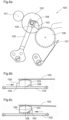
- the date mechanism 100 illustrated in figures 6a, 6b and 6c includes a device to prevent this. This mechanism is described in the book “Watchmaking theory Edition of the Federation of Technical Schools (FET), Switzerland, 2022”, p 200 . It includes, among other things, a twelve-hour wheel 101, a date star 106 positioned by a jumper 107 as well as a device comprising a twenty-four hour wheel 102, a twenty-four hour finger 103, a pin 104 driven on the wheel 102 and a spring bridge 105, said device connecting the twelve hour wheel 101 and the date star 106.
- FET Technical Schools
- the finger 103 of said device has the function of driving the date star 106 in the manner of a conventional finger while being able to retract if the user sets the time by turning the hands counterclockwise.
- the finger 103 has an inclined plane 108.
- the operation of the mechanism 100 is as follows. When the twelve-hour wheel 101 rotates clockwise (normal operating direction), the twenty-four hour wheel 102 is rotated counterclockwise. There pin 104 abuts against a first side of the finger 103 and rotates it so that it allows the date star 106 to rotate. If the user sets the time in the counterclockwise, the twenty-four hour wheel 102 turns in the opposite direction (clockwise in the example).
- the pin 104 meets the other side of the finger 103 and engages under the inclined plane 108.
- the finger 103 lifts and lets the pin 104 slide.
- the pin 104 also includes a plane inclined 109 to facilitate the lifting of the finger 103.
- the device comprising the wheel 102, the finger 103, the pin 104 and the spring bridge 105 is a bulky disengageable torque transmission device, both horizontally in particular due to the length of the blade of the spring bridge 105 and vertically in the to the extent that, when retracting, it requires free space above the finger 103 to allow it to rise.
- the guidance in the center of the finger 103 and the twenty-four hour wheel 102 must be mastered because good guidance without interference is required to allow the finger 103 to lift without blocking.
- the device according to the present invention has several advantages.
- the assembly composed of the stud and the spring makes it possible on the one hand to transmit the torque directly between the two members in the clutch direction (stud) and on the other hand to separate the two members in the disengagement direction. It has limited dimensions horizontally and vertically and the guidance of the first and second organ around the z axis is precise and limits the risk of blockage.
- the second member comprises a through opening and the first member comprises at least one opening, these openings being arranged so that there is at least one relative angular position of the first and second members called indexing position in which the opening of the second member is aligned with an opening of the first member and in which the stud passes through the opening of the second member to extend into said opening of the first member
- the device comprises as many indexing positions as openings in the first member.
- the openings are typically cylindrical holes with axes parallel to the z axis.
- the vector v essentially comprises a component in z, that is to say that the component along the z axis of the vector v is the majority. Moving the pad essentially along the z axis makes it possible to limit the bulk by limiting the dimension of the components in diameter.
- the opening(s) of the first member and/or the stud comprise an inclined surface allowing movement of the stud according to the vector v during disengagement.
- the or each of the openings of the first member comprises a surface parallel to the z axis intended to cooperate with a first surface of the stud parallel to the z axis and the stud comprises a second surface parallel to the z axis, intended to cooperate with a surface of the opening of the second member parallel to the z axis.
- the first and second members form a rigid connection via the stud so that the first and second members are united in rotation.
- the first member is typically a toothed wheel kinematically connected to the finishing gear of said timepiece, it is for example an hour toothed wheel.
- the second member is for its part typically chosen from a toothed wheel, a finger, a set of several fingers and a cam, preferably a snail cam, it is for example a finger or a snail cam intended to cooperate with a flip-flop for triggering a jumping display device.
- the device for a timepiece according to the invention is useful for controlling the display of any type of indication jumping periodically.
- the present invention also relates to a watch mechanism comprising a device as defined above. It is preferably a date mechanism.
- the invention also relates to a timepiece such as a wristwatch, a pocket watch, a clock or a clock comprising such a watch mechanism.
- a device 1 in reference to the figure 1 , comprises a toothed wheel 2 and a snail cam 3 intended to pivot around a common axis of rotation z.
- This device 1 is intended to be integrated into the watch mechanism of a timepiece such as a wristwatch, a pocket watch, a clock or even a pendulum.
- the toothed wheel 2 is typically a 24-hour wheel intended to pivot in a first direction, the clockwise direction in the example illustrated, and to drive the cam 3 with it.
- the cam 3 for its part typically cooperates with a trigger rocker (not illustrated) pivoting including a feeler.
- This feeler is held against the cam 3, typically by a spring, so that the rocker pivots by gradually arming the spring during the day then falls suddenly each day when its feeler passes from resting on the point high h to a press on the low point b of the snail cam 3.
- This cam 3 thus participates in advancing by one step each day a display of the date, the day of the week or the moon phase for example.
- the 24-hour wheel can be rotated in the direction opposite to its normal operating direction, that is to say in the example illustrated in the direction counterclockwise.
- the feeler of the aforementioned rocker and the wall of the snail cam 3 connecting its low point b to its high point h can be caused to abut against each other.
- this situation could lead to deformation or worse, breakage of the device 1 or said rocker.
- the cam 3 comprises a through cylindrical bore 4, extending parallel to the axis of rotation z.
- the axis of this drilling 4 is located at a distance d from the axis of rotation z.
- the toothed wheel 2 also includes a cylindrical drilling 5.
- the drilling 5 is typically of the same diameter as the drilling 4. It also extends parallel to the axis of rotation z and its axis is located at a distance d from this axis z.
- the cam 3 carries a stud 6 connected to the cam 3 via a spring 7.
- the stud 6 has a cylindrical shape, with a diameter slightly smaller than that of the holes 4 and 5.
- the spring 7 is mounted on the cam 3 by means of a fixing member such as a stud 8. It is arranged so that the axis of the stud 6 is located at the same distance d from the axis of rotation z as the holes 4 and 5.
- a first part 5a of the wall defining the hole 5 of the toothed wheel 2 abuts against a first part 6a (portion cylinder) of the wall of the stud 6 to rotate the stud 6 clockwise around the z axis.
- the walls 5a, 6a, 6b and 4a are parallel to each other and arranged perpendicular to the rotational movement around the z axis so that the toothed wheel 2 transmits its torque to the cam 3 via the plot 6 in the most direct way possible.
- the clearance between the stud 6 and the contours of the holes 4 and 5 guarantees free assembly and ensures that there is no constraint in the spring 7 during the winding function.
- a second part 5b of the wall defining the hole 5 of the toothed wheel 2 abuts against a third part 6c of the wall of the stud 6, located towards the end of the stud 6, to push the stud 6 with a torque tending to make it pivot counterclockwise around the axis z so that the first part 6a of the wall of the stud 6 abuts against a second part 4b of the wall defining the bore 4 of the cam 3, opposite the first 4a.
- the third part 6c of the wall of the stud 6 is a surface inclined relative to that 5b of the opening 5 so that, if the torque that the wall 5b must exert on the inclined surface 6c to rotate the stud 6 and the toothed wheel 2 in the counterclockwise direction is greater than a certain value, then this torque causes the stud 6 to slide against the wall 5b and causes a translation of the stud 6 along a vector substantially parallel to the z axis.
- This threshold value is typically exceeded when the wall of the snail cam 3 connecting its low point b to its high point h abuts against the feeler of the rocker with which the snail cam 3 cooperates.
- the second part 4b of the wall defining the drilling 4 of the cam 3 allows the guiding of the stud 6 along the z axis.
- part 6c of the wall of the stud 6 has an inclined surface but one could imagine that it is rather part 5b of the wall defining the hole 5 which has an inclined surface or both.
- the surfaces intended to slide against each other for the lifting of the stud 6 can thus have different profiles. The invention works from the moment when these surfaces allow sliding of the stud 6 against part 5b of the wall of the toothed wheel 2.
- the shape and orientation of the holes 4 and 5 and of the stud 6 could be different as long as they allow the disengagement of the toothed wheel 2 and the member 3 by movement of the stud 6 according to a vector having at least one component along the z axis, this component preferably being the majority component of the vector v.
- the device 1 according to the present invention is a clutch-disengagement device which offers an advantage over the mechanisms of the prior art in terms of size and precision of pivoting around the z axis.
- FIG. 4 shows a watchmaking device 1' according to a second embodiment which differs from that according to the first embodiment essentially in that the snail cam 3 is replaced by a simple finger 3'. It is typically a 24 hour finger whose function is to drive a date star in the manner of a conventional finger which retracts if the user sets the time by turning the hands in the clockwise direction. counterclockwise. All other considerations relating to the first form of execution remain valid for this second form.
- Objects bearing the references 2', 6', 7' and 8' at the Figure 4 correspond respectively to the objects bearing the references 2, 6, 7 and 8 to figures 1 to 3 .
- the finger 3' of the device 1' is indexed relative to the toothed wheel 2', which completes one revolution every 24 hours, so that it allows the star with which it cooperates, typically a date star, a day star or a moon phase star, to be moved by one step each day at midnight.
- FIG. 5 shows a 1" watch device according to a third embodiment which differs from that according to the second embodiment in that the toothed wheel 2" is typically a 72h wheel and in that the simple finger 3' is replaced by a triple finger 3" (set of three fingers).
- the toothed wheel 2" has three equidistant holes and the finger 3" has, like the finger 3' and the cam 3, a hole. These holes are all cylindrical, arranged parallel to the axis of rotation z and at the same distance d from this axis of rotation z.
- there are three distinct indexing positions for the device 1" in which the stud 6" passes through the drilling of the triple finger 3" and is inserts into one of the three holes of the 2" gear.
- Objects bearing the references 2", 6", 7" and 8" on the Figure 5 correspond respectively to the objects bearing the references 2, 6, 7 and 8 to figures 1 to 3 .
- the rotation speed of the different members is adapted to the intended use of the device within the timepiece. It can for example be as in the illustrated example of one revolution per 24 hours and typically make it possible to control a display of the date, day of the week or moon phase type. In another example it can be one revolution per month for a jumping display of the month etc.
- the holes 4, 5 are cylindrical but they can absolutely have another shape. We can more generally speak of openings to designate the possible variants of these drillings. Note also that certain shapes of openings, for example bean-shaped, require less precision as to their distance from the axis of rotation z. In theory, a common point allowing the connection between the first and second members via the stud is sufficient.
- the spring 7, 7', 7" connecting the stud 6, 6', 6" to the rest of the member 3, 3', 3" which carries it is of sinuous shape. This allows it to be lengthened and therefore to reduce its stiffness while maintaining limited bulk.
- the spring 7, 7', 7" as well as the pin 8, 8', 8" which allows its attachment are housed in a housing hollowed out in the member 3, 3', 3" which carries it. This allows the overall thickness of the device to be reduced.
Abstract
L'invention concerne un dispositif (1, 1', 1") pour pièce d'horlogerie comprenant un premier organe (2, 2', 2") et un deuxième organe (3, 3', 3") destinés à pivoter autour d'un axe de rotation z commun, ainsi qu'un plot (6, 6', 6") relié au deuxième organe (3, 3', 3") par l'intermédiaire d'un ressort (7, 7', 7"), le tout étant agencé de sorte que lorsque le premier organe (2, 2', 2") ou le deuxième organe (3, 3', 3") est entraîné en rotation dans un sens correspondant à un déplacement relatif desdits deux organes dit sens d'embrayage, l'un des deux organes (2, 3) presse le plot (6, 6', 6") contre l'autre pour former une liaison rigide entre le premier (2, 2', 2") et le deuxième (3, 3', 3") organe par l'intermédiaire du plot (6, 6', 6") de sorte que les premier et deuxième organes sont solidaires en rotation, et de sorte que lorsque le premier organe (2, 2', 2") ou le deuxième organe (3, 3', 3") est entraîné en rotation dans un sens correspondant à un déplacement relatif desdits deux organes dit sens de débrayage, opposé au sens d'embrayage, le plot (6, 6', 6") peut se déplacer selon un vecteur v ayant au moins une composante selon l'axe z en déformant élastiquement le ressort (7, 7', 7") de sorte que celui du premier organe (2, 2', 2") ou du deuxième organe (3, 3', 3") qui est entraîné en rotation pivote indépendamment de l'autre.The invention relates to a device (1, 1', 1") for a timepiece comprising a first member (2, 2', 2") and a second member (3, 3', 3") intended to pivot around a common axis of rotation z, as well as a stud (6, 6', 6") connected to the second member (3, 3', 3") via a spring (7, 7', 7"), the whole being arranged so that when the first member (2, 2', 2") or the second member (3, 3', 3") is rotated in a direction corresponding to a relative movement of said two members called clutch direction, one of the two members (2, 3) presses the stud (6, 6', 6") against the other to form a rigid connection between the first (2, 2', 2 ") and the second (3, 3', 3") member via the stud (6, 6', 6") so that the first and second members are integral in rotation, and so that when the first member (2, 2', 2") or the second member (3, 3', 3") is rotated in a direction corresponding to a relative movement of said two members called the disengagement direction, opposite to the clutch direction, the stud (6, 6', 6") can move according to a vector v having at least one component along the z axis by elastically deforming the spring (7, 7', 7") so that that of the first member ( 2, 2', 2") or the second member (3, 3', 3") which is driven in rotation pivots independently of the other.
Description
La présente invention concerne un dispositif d'embrayage-débrayage pour pièce d'horlogerie, un mécanisme horloger comprenant un tel dispositif et une pièce d'horlogerie comprenant un tel mécanisme.The present invention relates to a clutch-disengagement device for a timepiece, a watch mechanism comprising such a device and a timepiece comprising such a mechanism.
Dans la plupart des mécanismes de quantième simple, un doigt de quantième, solidaire d'une roue de vingt-quatre heures, permet l'entraînement d'un pas chaque jour d'une étoile de quantième. Si ce doigt est fixé rigidement sur la roue de vingt-quatre heures et que l'utilisateur effectue une mise à l'heure dans le sens inverse des aiguilles de la montre, le doigt entraîne l'étoile de trente-et-un dans le mauvais sens ou peut provoquer une casse, ce que l'on souhaite éviter.In most simple date mechanisms, a date finger, attached to a twenty-four hour wheel, allows the movement of one step each day of a date star. If this finger is rigidly fixed on the twenty-four hour wheel and the user sets the time counterclockwise, the finger pulls the thirty-one star in the wrong direction or can cause breakage, which we want to avoid.
Le mécanisme de quantième 100 illustré aux
La présente invention vise à proposer un dispositif pour pièce d'horlogerie comprenant un premier organe et un deuxième organe destinés à pivoter autour d'un axe de rotation z commun, ainsi qu'un plot relié au deuxième organe par l'intermédiaire d'un ressort. Le tout est agencé de sorte que :
- lorsque le premier organe ou le deuxième organe est entraîné en rotation dans un sens correspondant à un déplacement relatif desdits deux organes dit sens d'embrayage, l'un des deux organes presse le plot contre l'autre pour former une liaison rigide entre le premier et le deuxième organe par l'intermédiaire du plot de sorte que les premier et deuxième organes sont solidaires en rotation ; et de sorte que
- lorsque le premier organe ou le deuxième organe est entraîné en rotation dans un sens correspondant à un déplacement relatif desdits deux organes dit sens de débrayage, opposé au sens d'embrayage, le plot peut se déplacer selon un vecteur v ayant au moins une composante selon l'axe z en déformant élastiquement le ressort de sorte que celui du premier organe ou du deuxième organe qui est entraîné en rotation pivote indépendamment de l'autre.
- when the first member or the second member is rotated in a direction corresponding to a relative movement of said two members called clutch direction, one of the two members presses the stud against the other to form a rigid connection between the first and the second member via the stud so that the first and second members are united in rotation; and so that
- when the first member or the second member is rotated in a direction corresponding to a relative movement of said two members called the disengagement direction, opposite to the clutch direction, the stud can move according to a vector v having at least one component according to the z axis by elastically deforming the spring so that that of the first member or the second member which is driven in rotation pivots independently of the other.
Le dispositif selon la présente invention présente plusieurs avantages. L'ensemble composé du plot et du ressort permet d'une part de transmettre le couple de manière directe entre les deux organes dans le sens d'embrayage (plot) et d'autre part de désolidariser les deux organes dans le sens du débrayage. Il possède un encombrement limité horizontalement et verticalement et le guidage du premier et du second organe autour de l'axe z est précis et limite les risques de blocage.The device according to the present invention has several advantages. The assembly composed of the stud and the spring makes it possible on the one hand to transmit the torque directly between the two members in the clutch direction (stud) and on the other hand to separate the two members in the disengagement direction. It has limited dimensions horizontally and vertically and the guidance of the first and second organ around the z axis is precise and limits the risk of blockage.
Dans un mode de réalisation préféré de l'invention, le deuxième organe comprend une ouverture traversante et le premier organe comprend au moins une ouverture, ces ouvertures étant agencées de sorte qu'il existe au moins une position angulaire relative des premier et deuxième organes dite position d'indexation dans laquelle l'ouverture du deuxième organe est alignée avec une ouverture du premier organe et dans laquelle le plot traverse l'ouverture du deuxième organe pour s'étendre dans ladite ouverture du premier organeIn a preferred embodiment of the invention, the second member comprises a through opening and the first member comprises at least one opening, these openings being arranged so that there is at least one relative angular position of the first and second members called indexing position in which the opening of the second member is aligned with an opening of the first member and in which the stud passes through the opening of the second member to extend into said opening of the first member
De préférence, le dispositif comprend autant de positions d'indexation que d'ouvertures dans le premier organe. Les ouvertures sont typiquement des perçages cylindriques d'axes parallèles à l'axe z.Preferably, the device comprises as many indexing positions as openings in the first member. The openings are typically cylindrical holes with axes parallel to the z axis.
Avantageusement, le vecteur v comprend essentiellement une composante en z, c'est-à-dire que la composante selon l'axe z du vecteur v est majoritaire. Un déplacement du plot essentiellement selon l'axe z permet de limiter l'encombrement en limitant la dimension des composants en diamètre.Advantageously, the vector v essentially comprises a component in z, that is to say that the component along the z axis of the vector v is the majority. Moving the pad essentially along the z axis makes it possible to limit the bulk by limiting the dimension of the components in diameter.
De manière avantageuse, la ou les ouvertures du premier organe et/ou le plot comprennent une surface inclinée permettant le déplacement du plot selon le vecteur v lors du débrayage.Advantageously, the opening(s) of the first member and/or the stud comprise an inclined surface allowing movement of the stud according to the vector v during disengagement.
Avantageusement, pour l'embrayage, la ou chacune des ouvertures du premier organe comprend une surface parallèle à l'axe z destinée à coopérer avec une première surface du plot parallèle à l'axe z et le plot comprend une deuxième surface parallèle à l'axe z, destinée à coopérer avec une surface de l'ouverture du deuxième organe parallèle à l'axe z. De cette façon, au cours de l'embrayage, le premier et le deuxième organe forment une liaison rigide par l'intermédiaire du plot de sorte que les premier et deuxième organes sont solidaires en rotation.Advantageously, for the clutch, the or each of the openings of the first member comprises a surface parallel to the z axis intended to cooperate with a first surface of the stud parallel to the z axis and the stud comprises a second surface parallel to the z axis, intended to cooperate with a surface of the opening of the second member parallel to the z axis. In this way, during the clutch, the first and second members form a rigid connection via the stud so that the first and second members are united in rotation.
Le premier organe est typiquement une roue dentée reliée cinématiquement au rouage de finissage de ladite pièce d'horlogerie, il s'agit par exemple d'une roue dentée des heures. Le deuxième organe est quant à lui typiquement choisi parmi une roue dentée, un doigt, un ensemble de plusieurs doigts et une came de préférence une came escargot, il s'agit par exemple d'un doigt ou d'une came escargot destinée à coopérer avec une bascule de déclenchement d'un dispositif d'affichage sautant. En particulier lorsqu'il comprend une roue dentée et un doigt ou une came type came escargot, le dispositif pour pièce d'horlogerie selon l'invention est utile pour commander l'affichage de tout type d'indication sautant de manière périodique.The first member is typically a toothed wheel kinematically connected to the finishing gear of said timepiece, it is for example an hour toothed wheel. The second member is for its part typically chosen from a toothed wheel, a finger, a set of several fingers and a cam, preferably a snail cam, it is for example a finger or a snail cam intended to cooperate with a flip-flop for triggering a jumping display device. In particular when it comprises a toothed wheel and a finger or a snail cam type cam, the device for a timepiece according to the invention is useful for controlling the display of any type of indication jumping periodically.
La présente invention concerne également un mécanisme horloger comprenant un dispositif tel que défini ci-dessus. Il s'agit de préférence d'un mécanisme de quantième.The present invention also relates to a watch mechanism comprising a device as defined above. It is preferably a date mechanism.
L'invention concerne également une pièce d'horlogerie telle qu'une montre bracelet, une montre de poche, une pendule ou une pendulette comprenant un tel mécanisme horloger.The invention also relates to a timepiece such as a wristwatch, a pocket watch, a clock or a clock comprising such a watch mechanism.
D'autres caractéristiques et avantages de la présente invention apparaîtront à la lecture de la description détaillée suivante faite en référence aux dessins annexés dans lesquels :
- la
figure 1 est une vue en perspective de dessus d'un dispositif horloger selon un premier mode de réalisation particulier de l'invention ; - la
figure 2 est une coupe perspective du mécanisme de lafigure 1 ; - la
figure 3 est une coupe transversale du mécanisme de lafigure 1 ; - la
figure 4 est une vue en perspective de dessus d'un dispositif horloger selon un deuxième mode de réalisation de l'invention ; - la
figure 5 est une vue en perspective de dessus d'un dispositif horloger selon un troisième mode de réalisation de l'invention ; - les
figures 6a à 6c illustrent un mécanisme de quantième selon l'art antérieur.
- there
figure 1 is a top perspective view of a watch device according to a first particular embodiment of the invention; - there
figure 2 is a perspective section of the mechanism of thefigure 1 ; - there
Figure 3 is a cross section of the mechanism of thefigure 1 ; - there
Figure 4 is a top perspective view of a watch device according to a second embodiment of the invention; - there
Figure 5 is a top perspective view of a watch device according to a third embodiment of the invention; - THE
figures 6a to 6c illustrate a date mechanism according to the prior art.
En référence à la
Ce dispositif 1 est destiné à être intégré dans le mécanisme horloger d'une pièce d'horlogerie telle qu'une montre bracelet, une montre de poche, une pendule ou encore une pendulette. La roue dentée 2 est typiquement une roue de 24h destinée à pivoter dans un premier sens, le sens horaire dans l'exemple illustré, et à entraîner avec elle la came 3. La came 3 coopère quant à elle typiquement avec une bascule de déclenchement (non illustrée) pivotante comprenant un palpeur. Ce palpeur est maintenu en appui contre la came 3, typiquement par un ressort, de sorte que la bascule pivote en armant petit à petit le ressort au cours de la journée puis tombe brutalement chaque jour lorsque son palpeur passe d'un appui sur le point haut h à un appui sur le point bas b de la came escargot 3. Cette came 3 participe ainsi à faire avancer d'un pas chaque jour un affichage de quantième, du jour de la semaine ou de phase de lune par exemple.This
Lors de la mise à l'heure de la montre comprenant le dispositif 1, la roue de 24h peut être entraînée en rotation dans le sens opposé à son sens de fonctionnement normal c'est-à-dire dans l'exemple illustré dans le sens antihoraire. Dans ce cas, le palpeur de la bascule précitée et la paroi de la came escargot 3 reliant son point bas b à son point haut h peuvent être amenés à buter l'un contre l'autre. A défaut d'une solution pour éviter cela, cette situation pourrait aboutir à des déformations ou pire une casse du dispositif 1 ou de ladite bascule. Pour éviter cela, il est nécessaire de débrayer la roue dentée 2 et la came 3 dès lors que la came 3 vient forcer contre la bascule de déclenchement de sorte que le pivotement de la roue dentée 2 dans le sens antihoraire puisse ne pas entraîner la rotation de la came 3.When setting the time of the watch comprising the
Le dispositif 1 permet un tel débrayage. A cette fin, la came 3 comporte un perçage 4 cylindrique traversant, s'étendant parallèlement à l'axe de rotation z. L'axe de ce perçage 4 se situe à une distance d de l'axe de rotation z. La roue dentée 2 comprend également un perçage cylindrique 5. Le perçage 5 est typiquement de même diamètre que le perçage 4. Il s'étend également parallèlement à l'axe de rotation z et son axe est situé à une distance d de cet axe z.
La came 3 porte un plot 6 relié à la came 3 par l'intermédiaire d'un ressort 7. Le plot 6 a une forme cylindrique, de diamètre légèrement inférieur à celui des perçages 4 et 5. Le ressort 7 est monté sur la came 3 au moyen d'un organe de fixation tel qu'un téton 8. Il est agencé de sorte que l'axe du plot 6 se situe à la même distance d de l'axe de rotation z que les perçages 4 et 5.The
Il existe une position relative de la came 3 et de la roue dentée 2 dans laquelle le plot 6 traverse le perçage 4 et est inséré dans le perçage 5, c'est pourquoi il est important que les axes des perçages 4 et 5 et du plot 6 se situent à la même distance d de l'axe de rotation z. Lorsque le plot 6 se situe à l'intérieur des perçages 4 et 5, la position de la came 3 est indexée par rapport à la roue dentée 2. Elle est telle que la chute de la bascule de déclenchement du point haut h au point bas b s'effectue le plus proche possible de minuit. Le dispositif 1 est agencé de sorte que, dans cette position relative de la came 3 et de la roue dentée 2, le ressort 7 est en position de repos et n'exerce pas de force de rappel élastique. En variante, le ressort 7 pourrait être pré-armé pour exercer une force « poussant » le plot 6 vers le bas.There is a relative position of the
Lorsque la roue dentée 2 est pivotée dans le sens horaire, typiquement lors du fonctionnement normal de la pièce d'horlogerie, une première partie 5a de la paroi définissant le perçage 5 de la roue dentée 2 vient en butée contre une première partie 6a (portion de cylindre) de la paroi du plot 6 pour faire pivoter le plot 6 dans le sens horaire autour de l'axe z. Une seconde partie 6b (portion de cylindre) de la paroi du plot 6, opposée à la première, vient alors en butée contre une première partie 4a de la paroi définissant le perçage 4 de la came 3. Les parois 5a, 6a, 6b et 4a sont parallèles les unes aux autres et agencées perpendiculairement au mouvement de rotation autour de l'axe z de sorte que la roue dentée 2 transmet son couple à la came 3 par l'intermédiaire du plot 6 de la façon la plus directe possible. Le jeu entre le plot 6 et les contours des perçages 4 et 5 garanti le montage libre et permet qu'il n'y ait pas de contrainte dans le ressort 7 lors de la fonction d'armage.When the
Lorsque la roue dentée 2 est pivotée dans le sens anti-horaire, typiquement lors d'une correction de l'heure, une deuxième partie 5b de la paroi définissant le perçage 5 de la roue dentée 2 vient en butée contre une troisième partie 6c de la paroi du plot 6, située vers l'extrémité du plot 6, pour pousser le plot 6 avec un couple tendant à le faire pivoter dans le sens antihoraire autour de l'axe z de sorte que la première partie 6a de la paroi du plot 6 vienne en butée contre une deuxième partie 4b de la paroi définissant le perçage 4 de la came 3, opposée à la première 4a.When the
La troisième partie 6c de la paroi du plot 6 est une surface inclinée par rapport à celle 5b de l'ouverture 5 de sorte que, si le couple que doit exercer la paroi 5b sur la surface inclinée 6c pour faire pivoter le plot 6 et la roue dentée 2 dans le sens antihoraire est supérieur à une certaine valeur, alors ce couple entraîne un glissement du plot 6 contre la paroi 5b et provoque une translation du plot 6 selon un vecteur sensiblement parallèle à l'axe z. Cette valeur seuil est typiquement dépassée lorsque la paroi de la came escargot 3 reliant son point bas b à son point haut h bute contre le palpeur de la bascule avec laquelle la came escargot 3 coopère. Dans l'exemple illustré, la deuxième partie 4b de la paroi définissant le perçage 4 de la came 3 permet le guidage plot 6 le long de l'axe z.The
Dans l'exemple illustré la partie 6c de la paroi du plot 6 présente une surface inclinée mais on pourrait imaginer que ce soit plutôt la partie 5b de la paroi définissant le perçage 5 qui présente une surface inclinée ou bien les deux. Les surfaces destinées à glisser l'une contre l'autre pour le soulèvement du plot 6 peuvent ainsi avoir différents profils. L'invention fonctionne à partir du moment où ces surfaces autorisent un glissement du plot 6 contre la partie 5b de la paroi de la roue dentée 2.In the example illustrated,
La forme et l'orientation des perçages 4 et 5 et du plot 6 pourraient être différentes du moment qu'elles permettent le débrayage de la roue dentée 2 et de l'organe 3 par déplacement du plot 6 selon un vecteur ayant au moins une composante selon l'axe z, cette composante étant de préférence la composante majoritaire du vecteur v.The shape and orientation of the
Le dispositif 1 selon la présente invention est un dispositif d'embrayage-débrayage qui offre un avantage sur les mécanismes de l'art antérieur en termes d'encombrement et de précision du pivotement autour de l'axe z.The
La
Similairement au premier mode de réalisation de l'invention, le doigt 3' du dispositif 1' selon le second mode de réalisation de l'invention est indexé par rapport à la roue dentée 2', qui effectue un tour chaque 24h, de sorte qu'il permet d'entraîner l'étoile avec laquelle il coopère, typiquement une étoile de quantième, une étoile des jours ou de phase de lune, d'un pas chaque jour à minuit.Similar to the first embodiment of the invention, the finger 3' of the device 1' according to the second embodiment of the invention is indexed relative to the toothed wheel 2', which completes one revolution every 24 hours, so that it allows the star with which it cooperates, typically a date star, a day star or a moon phase star, to be moved by one step each day at midnight.
La
La description qui précède s'attache à décrire un mode de réalisation particulier à titre d'illustration non limitative, et l'invention n'est pas limitée à la mise en oeuvre de certaines caractéristiques particulières qui viennent d'être décrites, comme par exemple les formes représentées pour les différents constituants, les types de composants formant les premier et deuxième organes pivotants et les vitesses de révolution de ces organes.The preceding description attempts to describe a particular embodiment by way of non-limiting illustration, and the invention is not limited to the implementation of certain particular characteristics which have just been described, such as for example the shapes represented for the different constituents, the types of components forming the first and second pivoting members and the speeds of revolution of these members.
Nous venons de décrire le fonctionnement de dispositifs 1, 1', 1" selon l'invention dans des cas particuliers dans lesquels un organe particulier (roue dentée 2, 2', 2") est destiné à entraîner ou non un autre organe (came 3, doigt simple 3', doigt triple 3") en rotation. Cela dit, il est tout à fait envisageable d'utiliser un dispositif conforme à l'invention dans un contexte dans lequel n'importe lequel des deux organes destinés à pivoter autour de l'axe z (roue dentée 2 et came 3 ici) peut être le moteur de l'autre.We have just described the operation of
Quel que soit l'organe que le rouage entraîne en rotation, c'est le sens de rotation de cet organe relativement à l'autre qui détermine si on est dans le sens d'embrayage ou de débrayage.Whatever the organ that the cog drives in rotation, it is the direction of rotation of this organ relative to the other which determines whether we are in the clutch or disengagement direction.
La vitesse de rotation des différents organes est adaptée à l'utilisation prévue pour le dispositif au sein de la pièce d'horlogerie. Elle peut par exemple être comme dans l'exemple illustrée d'un tour par 24h et permettre typiquement de commander un affichage du type quantième, jour de la semaine ou phase de lune. Dans un autre exemple elle peut être d'un tour par mois pour un affichage sautant du mois etc... Dans les exemples illustrés, les perçages 4, 5 sont cylindriques mais ils peuvent tout à fait avoir une autre forme. On peut plus généralement parler d'ouvertures pour désigner les variantes possibles de ces perçages. Notons également que certaines formes d'ouvertures, par exemple en forme de haricot, demandent moins de précision quant à leur distance à l'axe de rotation z. Il suffit en théorie d'un point commun permettant la liaison entre les premier et deuxième organes par l'intermédiaire du plot.The rotation speed of the different members is adapted to the intended use of the device within the timepiece. It can for example be as in the illustrated example of one revolution per 24 hours and typically make it possible to control a display of the date, day of the week or moon phase type. In another example it can be one revolution per month for a jumping display of the month etc. In the examples illustrated, the
Dans les modes de réalisation illustrés, le ressort 7, 7', 7" reliant le plot 6, 6', 6" au reste de l'organe 3, 3', 3" qui le porte est de forme sinueuse. Cela permet de l'allonger et donc de diminuer sa raideur tout en conservant un encombrement limité.In the illustrated embodiments, the
Dans les exemples illustrés le ressort 7, 7', 7" ainsi que le téton 8, 8', 8" qui permet sa fixation sont logés dans un logement creusé dans l'organe 3, 3 ', 3" qui le porte. Cela permet de diminuer l'épaisseur globale du dispositif.In the examples illustrated, the
Claims (12)
Priority Applications (1)
| Application Number | Priority Date | Filing Date | Title |
|---|---|---|---|
| EP22186743.5A EP4312083A1 (en) | 2022-07-25 | 2022-07-25 | Clutch engagement-disengagement device for a timepiece |
Applications Claiming Priority (1)
| Application Number | Priority Date | Filing Date | Title |
|---|---|---|---|
| EP22186743.5A EP4312083A1 (en) | 2022-07-25 | 2022-07-25 | Clutch engagement-disengagement device for a timepiece |
Publications (1)
| Publication Number | Publication Date |
|---|---|
| EP4312083A1 true EP4312083A1 (en) | 2024-01-31 |
Family
ID=82703143
Family Applications (1)
| Application Number | Title | Priority Date | Filing Date |
|---|---|---|---|
| EP22186743.5A Pending EP4312083A1 (en) | 2022-07-25 | 2022-07-25 | Clutch engagement-disengagement device for a timepiece |
Country Status (1)
| Country | Link |
|---|---|
| EP (1) | EP4312083A1 (en) |
Citations (3)
| Publication number | Priority date | Publication date | Assignee | Title |
|---|---|---|---|---|
| US3623582A (en) * | 1969-01-16 | 1971-11-30 | Ebauchesfabrik Eta Ag | Free-wheel mechanism |
| JPS50157963U (en) * | 1974-06-17 | 1975-12-27 | ||
| CH715773A2 (en) * | 2019-01-24 | 2020-07-31 | Richemont Int Sa | Secure drive system. |
-
2022
- 2022-07-25 EP EP22186743.5A patent/EP4312083A1/en active Pending
Patent Citations (3)
| Publication number | Priority date | Publication date | Assignee | Title |
|---|---|---|---|---|
| US3623582A (en) * | 1969-01-16 | 1971-11-30 | Ebauchesfabrik Eta Ag | Free-wheel mechanism |
| JPS50157963U (en) * | 1974-06-17 | 1975-12-27 | ||
| CH715773A2 (en) * | 2019-01-24 | 2020-07-31 | Richemont Int Sa | Secure drive system. |
Similar Documents
| Publication | Publication Date | Title |
|---|---|---|
| EP2428855B1 (en) | Clock piece fitted with a device for displaying predetermined time periods | |
| EP3483663B1 (en) | Drive device for clock calendar system | |
| EP1978420B1 (en) | Gear wheel for a timepiece and device for correction of a display mechanism for a timepiece incorporating such a wheel | |
| EP3584643B1 (en) | Instantaneous command device for date display of timepieces | |
| EP1978419B1 (en) | Winding device comprising a unidirectional coupling | |
| EP3489766A1 (en) | Mechanism for correcting a function of a timepiece movement | |
| EP4312083A1 (en) | Clutch engagement-disengagement device for a timepiece | |
| EP3602202B1 (en) | Device for adjusting functions of a timepiece | |
| EP1890202A1 (en) | Control device for a clock piece | |
| EP1960843B1 (en) | Timepiece movement | |
| EP3376308B1 (en) | Winding mechanism of a timepiece | |
| CH715052A2 (en) | Constant torque mechanism, timepiece movement, and timepiece. | |
| EP3246763B1 (en) | Quick correction mechanism for clock piece | |
| EP2884345A2 (en) | Jumper for clockwork | |
| EP1925996A1 (en) | Device for correction of a display mechanism for a timepiece | |
| EP1960846B1 (en) | Clockwork movement | |
| CH708338A2 (en) | corrective mechanism step by step. | |
| EP3855255B1 (en) | Locking device for timepieces | |
| CH717664B1 (en) | Timepiece comprising a waterproof control device. | |
| EP2160659B1 (en) | Device for actuating in its drop a large rocker for controlling the display of an instantaneous date mechanism of a timepiece having a perpetual or secular date mechanism | |
| EP4012505A1 (en) | Timepiece device with anti-blocking mobile | |
| EP0063543A1 (en) | Timepiece with control mechanism | |
| EP2503406B1 (en) | Shock-absorber device for clock mechanism | |
| FR3023934A1 (en) | WATCHMAKING MECHANISM | |
| WO2024038348A1 (en) | Perpetual calendar mechanism with concentric cams |
Legal Events
| Date | Code | Title | Description |
|---|---|---|---|
| PUAI | Public reference made under article 153(3) epc to a published international application that has entered the european phase |
Free format text: ORIGINAL CODE: 0009012 |
|
| STAA | Information on the status of an ep patent application or granted ep patent |
Free format text: STATUS: THE APPLICATION HAS BEEN PUBLISHED |
|
| AK | Designated contracting states |
Kind code of ref document: A1 Designated state(s): AL AT BE BG CH CY CZ DE DK EE ES FI FR GB GR HR HU IE IS IT LI LT LU LV MC MK MT NL NO PL PT RO RS SE SI SK SM TR |