EP4311678A2 - Liquid ejection apparatus - Google Patents
Liquid ejection apparatus Download PDFInfo
- Publication number
- EP4311678A2 EP4311678A2 EP23188068.3A EP23188068A EP4311678A2 EP 4311678 A2 EP4311678 A2 EP 4311678A2 EP 23188068 A EP23188068 A EP 23188068A EP 4311678 A2 EP4311678 A2 EP 4311678A2
- Authority
- EP
- European Patent Office
- Prior art keywords
- recording
- unit
- cap
- cleaning
- sheet
- Prior art date
- Legal status (The legal status is an assumption and is not a legal conclusion. Google has not performed a legal analysis and makes no representation as to the accuracy of the status listed.)
- Granted
Links
Images









Classifications
-
- B—PERFORMING OPERATIONS; TRANSPORTING
- B41—PRINTING; LINING MACHINES; TYPEWRITERS; STAMPS
- B41J—TYPEWRITERS; SELECTIVE PRINTING MECHANISMS, i.e. MECHANISMS PRINTING OTHERWISE THAN FROM A FORME; CORRECTION OF TYPOGRAPHICAL ERRORS
- B41J2/00—Typewriters or selective printing mechanisms characterised by the printing or marking process for which they are designed
- B41J2/005—Typewriters or selective printing mechanisms characterised by the printing or marking process for which they are designed characterised by bringing liquid or particles selectively into contact with a printing material
- B41J2/01—Ink jet
- B41J2/135—Nozzles
- B41J2/165—Prevention or detection of nozzle clogging, e.g. cleaning, capping or moistening for nozzles
- B41J2/16505—Caps, spittoons or covers for cleaning or preventing drying out
- B41J2/16508—Caps, spittoons or covers for cleaning or preventing drying out connected with the printer frame
-
- B—PERFORMING OPERATIONS; TRANSPORTING
- B41—PRINTING; LINING MACHINES; TYPEWRITERS; STAMPS
- B41J—TYPEWRITERS; SELECTIVE PRINTING MECHANISMS, i.e. MECHANISMS PRINTING OTHERWISE THAN FROM A FORME; CORRECTION OF TYPOGRAPHICAL ERRORS
- B41J2/00—Typewriters or selective printing mechanisms characterised by the printing or marking process for which they are designed
- B41J2/005—Typewriters or selective printing mechanisms characterised by the printing or marking process for which they are designed characterised by bringing liquid or particles selectively into contact with a printing material
- B41J2/01—Ink jet
- B41J2/135—Nozzles
- B41J2/165—Prevention or detection of nozzle clogging, e.g. cleaning, capping or moistening for nozzles
- B41J2/16505—Caps, spittoons or covers for cleaning or preventing drying out
- B41J2/16508—Caps, spittoons or covers for cleaning or preventing drying out connected with the printer frame
- B41J2/16511—Constructions for cap positioning
-
- B—PERFORMING OPERATIONS; TRANSPORTING
- B41—PRINTING; LINING MACHINES; TYPEWRITERS; STAMPS
- B41J—TYPEWRITERS; SELECTIVE PRINTING MECHANISMS, i.e. MECHANISMS PRINTING OTHERWISE THAN FROM A FORME; CORRECTION OF TYPOGRAPHICAL ERRORS
- B41J2/00—Typewriters or selective printing mechanisms characterised by the printing or marking process for which they are designed
- B41J2/005—Typewriters or selective printing mechanisms characterised by the printing or marking process for which they are designed characterised by bringing liquid or particles selectively into contact with a printing material
- B41J2/01—Ink jet
- B41J2/135—Nozzles
- B41J2/165—Prevention or detection of nozzle clogging, e.g. cleaning, capping or moistening for nozzles
- B41J2/16517—Cleaning of print head nozzles
- B41J2/16535—Cleaning of print head nozzles using wiping constructions
-
- B—PERFORMING OPERATIONS; TRANSPORTING
- B41—PRINTING; LINING MACHINES; TYPEWRITERS; STAMPS
- B41J—TYPEWRITERS; SELECTIVE PRINTING MECHANISMS, i.e. MECHANISMS PRINTING OTHERWISE THAN FROM A FORME; CORRECTION OF TYPOGRAPHICAL ERRORS
- B41J2/00—Typewriters or selective printing mechanisms characterised by the printing or marking process for which they are designed
- B41J2/005—Typewriters or selective printing mechanisms characterised by the printing or marking process for which they are designed characterised by bringing liquid or particles selectively into contact with a printing material
- B41J2/01—Ink jet
- B41J2/135—Nozzles
- B41J2/165—Prevention or detection of nozzle clogging, e.g. cleaning, capping or moistening for nozzles
- B41J2/16517—Cleaning of print head nozzles
- B41J2/16535—Cleaning of print head nozzles using wiping constructions
- B41J2/16538—Cleaning of print head nozzles using wiping constructions with brushes or wiper blades perpendicular to the nozzle plate
-
- B—PERFORMING OPERATIONS; TRANSPORTING
- B41—PRINTING; LINING MACHINES; TYPEWRITERS; STAMPS
- B41J—TYPEWRITERS; SELECTIVE PRINTING MECHANISMS, i.e. MECHANISMS PRINTING OTHERWISE THAN FROM A FORME; CORRECTION OF TYPOGRAPHICAL ERRORS
- B41J2/00—Typewriters or selective printing mechanisms characterised by the printing or marking process for which they are designed
- B41J2/005—Typewriters or selective printing mechanisms characterised by the printing or marking process for which they are designed characterised by bringing liquid or particles selectively into contact with a printing material
- B41J2/01—Ink jet
- B41J2/135—Nozzles
- B41J2/165—Prevention or detection of nozzle clogging, e.g. cleaning, capping or moistening for nozzles
- B41J2/16517—Cleaning of print head nozzles
- B41J2/16535—Cleaning of print head nozzles using wiping constructions
- B41J2/16544—Constructions for the positioning of wipers
-
- B—PERFORMING OPERATIONS; TRANSPORTING
- B41—PRINTING; LINING MACHINES; TYPEWRITERS; STAMPS
- B41J—TYPEWRITERS; SELECTIVE PRINTING MECHANISMS, i.e. MECHANISMS PRINTING OTHERWISE THAN FROM A FORME; CORRECTION OF TYPOGRAPHICAL ERRORS
- B41J25/00—Actions or mechanisms not otherwise provided for
- B41J25/304—Bodily-movable mechanisms for print heads or carriages movable towards or from paper surface
-
- B—PERFORMING OPERATIONS; TRANSPORTING
- B41—PRINTING; LINING MACHINES; TYPEWRITERS; STAMPS
- B41J—TYPEWRITERS; SELECTIVE PRINTING MECHANISMS, i.e. MECHANISMS PRINTING OTHERWISE THAN FROM A FORME; CORRECTION OF TYPOGRAPHICAL ERRORS
- B41J2/00—Typewriters or selective printing mechanisms characterised by the printing or marking process for which they are designed
- B41J2/005—Typewriters or selective printing mechanisms characterised by the printing or marking process for which they are designed characterised by bringing liquid or particles selectively into contact with a printing material
- B41J2/01—Ink jet
- B41J2/135—Nozzles
- B41J2/165—Prevention or detection of nozzle clogging, e.g. cleaning, capping or moistening for nozzles
- B41J2/16517—Cleaning of print head nozzles
- B41J2/1652—Cleaning of print head nozzles by driving a fluid through the nozzles to the outside thereof, e.g. by applying pressure to the inside or vacuum at the outside of the print head
- B41J2/16532—Cleaning of print head nozzles by driving a fluid through the nozzles to the outside thereof, e.g. by applying pressure to the inside or vacuum at the outside of the print head by applying vacuum only
-
- B—PERFORMING OPERATIONS; TRANSPORTING
- B41—PRINTING; LINING MACHINES; TYPEWRITERS; STAMPS
- B41J—TYPEWRITERS; SELECTIVE PRINTING MECHANISMS, i.e. MECHANISMS PRINTING OTHERWISE THAN FROM A FORME; CORRECTION OF TYPOGRAPHICAL ERRORS
- B41J2/00—Typewriters or selective printing mechanisms characterised by the printing or marking process for which they are designed
- B41J2/005—Typewriters or selective printing mechanisms characterised by the printing or marking process for which they are designed characterised by bringing liquid or particles selectively into contact with a printing material
- B41J2/01—Ink jet
- B41J2/135—Nozzles
- B41J2/165—Prevention or detection of nozzle clogging, e.g. cleaning, capping or moistening for nozzles
- B41J2/16585—Prevention or detection of nozzle clogging, e.g. cleaning, capping or moistening for nozzles for paper-width or non-reciprocating print heads
-
- B—PERFORMING OPERATIONS; TRANSPORTING
- B41—PRINTING; LINING MACHINES; TYPEWRITERS; STAMPS
- B41J—TYPEWRITERS; SELECTIVE PRINTING MECHANISMS, i.e. MECHANISMS PRINTING OTHERWISE THAN FROM A FORME; CORRECTION OF TYPOGRAPHICAL ERRORS
- B41J2/00—Typewriters or selective printing mechanisms characterised by the printing or marking process for which they are designed
- B41J2/005—Typewriters or selective printing mechanisms characterised by the printing or marking process for which they are designed characterised by bringing liquid or particles selectively into contact with a printing material
- B41J2/01—Ink jet
- B41J2/135—Nozzles
- B41J2/165—Prevention or detection of nozzle clogging, e.g. cleaning, capping or moistening for nozzles
- B41J2/16517—Cleaning of print head nozzles
- B41J2/16552—Cleaning of print head nozzles using cleaning fluids
- B41J2002/16558—Using cleaning liquid for wet wiping
Definitions
- the present invention relates to a liquid ejection apparatus for ejecting liquid.
- Inkjet recording apparatuses are a type of liquid ejection apparatus. They each include a recording head provided with nozzles that each contain ink that can lose moisture, causing its thickening or solidification. Further, paper dust or air bubbles can enter a nozzle of the recording head, resulting in an ejection failure. To address those issues, inkjet recording apparatuses generally perform cleaning of their recording heads.
- Japanese Patent Application Laid-Open No. 2011-240550 discloses a configuration in which a cleaning mechanism for cleaning the nozzle surface of a recording head and a cap for covering the nozzle surface are integrally arranged as a cleaning unit.
- the cleaning unit in Japanese Patent Application Laid-Open No. 2011-240550 includes the cleaning mechanism and the cap arranged side by side in a sheet width direction.
- the arrangement of the cleaning mechanism and the cap side by side in the sheet width direction, and configured to move integrally, as described in Japanese Patent Application Laid-Open No. 2011-240550 may result in the apparatus being configured with a larger dimension in the sheet width direction.
- the present invention is directed to providing a liquid ejection apparatus to prevent an apparatus from being large in size.
- “recording” is not limited to the case of forming significant information such as characters and graphics.
- the term “recording” broadly includes a case where, for example, an image, a design, or a pattern is formed on a recording medium or a case where a medium is processed regardless of whether the recording is significant or insignificant, and it does not matter whether the recording is actualized so as to be visually perceived by a human or not.
- a “recording medium” is assumed to be a sheet of paper, but may be, for example, a cloth or a plastic film.
- Fig. 1 is a schematic cross-sectional view of the internal configuration of a recording apparatus 1 as a liquid ejection apparatus according to the first embodiment of the present invention.
- an x direction indicates the width direction of the recording apparatus 1
- a y direction indicates the rear direction of the recording apparatus 1
- a z direction indicates the height direction of the recording apparatus 1.
- the recording apparatus 1 includes a sheet feeding unit 2, a first dancer unit 3, a first conveying unit 4, a skew correcting unit 5, a detecting unit 6, a mark sensor unit 7, and a recording unit 8.
- the recording apparatus 1 further includes a first scanner unit 9, a first drying unit 10, a second drying unit 11, a cooling unit 12, a second scanner unit 13, a second conveying unit 14, a second dancer unit 15, a winding unit 16, and a maintenance unit 17.
- a sheet S (e.g., a recording medium) is conveyed along a sheet conveyance path indicated by a solid line in Fig. 1 , and is processed by the above-described units.
- the sheet feeding unit 2 is configured to hold and store a continuous sheet wound in a roll shape and to draw out and feed the sheet S.
- the number of storable rolls is not limited to one. For example, two or three or more rolls may be stored.
- the sheet S may be selectively pulled out and supplied from one of the plurality of stored rolls.
- the first dancer unit 3 is a unit for applying a constant tension to the sheet S between the sheet feeding unit 2 and the first conveying unit 4. A sheet tension is applied to the first dancer unit 3 by a tension applying unit (not illustrated).
- the first conveying unit 4 is a unit for conveying the sheet S toward the skew correcting unit 5, the detecting unit 6, the mark sensor unit 7, the recording unit 8, the first scanner unit 9, the first drying unit 10, the second drying unit 11, the cooling unit 12, and the second scanner unit 13, all of which are arranged in this order along the sheet conveyance path.
- the first conveying unit 4 also serves as a unit for applying tension to the sheet S between the first conveying unit 4 and the second conveying unit 14.
- the first conveying unit 4 is rotated by driving a motor (not illustrated), and performs tension conveyance of the sheet S together with the second conveying unit 14.
- the skew correcting unit 5 is a unit for correcting a skew of the sheet S in the conveyance of the sheet S.
- the skew correcting unit 5 includes a skew correcting roller 5a and a skew detecting sensor (not illustrated) for detecting a skew of the sheet S.
- the skew correcting roller 5a can change an inclination of the sheet S by a motor (not illustrated), and corrects a skew of the sheet S based on a detection result of the skew detecting sensor. At this time, winding the sheet S around the skew correcting roller 5a heightens the effect of skew correction.
- the detecting unit 6 is a unit for detecting a tension applied to the sheet S when the sheet S is tension-conveyed between the first conveying unit 4 and the second conveying unit 14. Further, the detecting unit 6 is a unit including a mechanism for detecting a conveyance speed of the sheet S in order to control an image forming timing (ejection timing) in the recording unit 8.
- the mark sensor unit 7 is a unit for detecting marks printed on the sheet S in advance in order to control the image forming timing of the recording unit 8.
- the recording unit 8 is a sheet processing unit for performing a recording process by forming an image as an example by ink as a recording liquid being ejected by at least one recording head 22, or ejection head, (e.g., a plurality of recording heads 22) from above onto the sheet S being conveyed.
- the sheet conveyance path in the recording unit 8 is formed by a plurality of guide rollers 23 arranged in an arc shape which is convex upward (i.e., a straight line drawn between two points of the arc shape is always below the arc shape).
- a constant tension applied to the sheet S by the first conveying unit 4 and the second conveying unit 14 forms a clearance (e.g., interval) of a predetermined distance between the recording heads 22 and the sheet S.
- the recording apparatus 1 is an inkjet recording apparatus in which the plurality of recording heads 22 are arranged in the x direction.
- a total of eight recording heads 22 including the recording heads 22 for a reaction liquid and three special colors are provided so that one recording head is assigned to each color of ink, and the other recording head to the reaction liquid.
- the recording heads 22 are each a full-line recording head in which nozzles (e.g., ejection ports) are arrayed over a length corresponding to the width direction of the sheet S.
- the number of ink colors and a reaction liquid and the number of recording heads 22 are not limited to eight.
- the ink of each color is supplied to the corresponding recording head 22 from its ink tank serving as a liquid container (not illustrated) through a supply path of, for example, a tube.
- An ejecting element is disposed in each nozzle of the recording heads 22.
- An ejecting element is, for example, an element which ejects ink in its nozzle by pressure generated in its nozzle, and can use a technique for an inkjet recording head of known inkjet printers.
- Examples of the ejecting element include an element that ejects ink by film boiling the ink with an electrothermal transducer to create a bubble, an element that ejects ink by an electromechanical transducer, an element that ejects ink using static electricity, and a micro-electro-mechanical systems (MEMS) element. From the viewpoint of high-speed and high-density recording, an ejecting element using an electrothermal transducer can be used.
- the first scanner unit 9 is a unit for reading an image formed on the sheet S by the recording unit 8, detecting the deviation and the density of the image, and correcting the recording process by the recording unit 8. After passing through the first scanner unit 9, the sheet S is conveyed in the sheet conveyance direction, which is reversed by a guide roller 31.
- the first drying unit 10 and the second drying unit 11 are units that reduce the moisture contained in the ink applied onto the sheet S by the recording unit 8 and increase the fixability of the ink to the sheet S.
- the second drying unit 11 is disposed downstream of the first drying unit 10 in the sheet conveyance direction. The first drying unit 10 and the second drying unit 11 dry the ink applied to the sheet S by applying hot air to at least the ink applied surface (e.g., recording surface) of the passing sheet S.
- a method of irradiating the surface of the sheet S with electromagnetic waves such as ultraviolet rays or infrared rays
- a method of conduction heat transfer performed by contact with a heating element or a combination of a plurality of these methods may be adopted.
- the guide roller 31 is a roller that winds the back surface of the recording surface of the sheet S at a constant winding angle in order to prevent the hot air in the first drying unit 10 from affecting the recording process in the recording unit 8.
- Two guide rollers 31 according to the present embodiment are disposed between the first scanner unit 9 and the first drying unit 10.
- the sheet S is turned around in the vertical direction of the recording apparatus 1 and is conveyed such that the sheet conveyance direction is reversed.
- the first drying unit 10 is disposed under the recording unit 8
- the second drying unit 11 is disposed under the detecting unit 6 and the mark sensor unit 7.
- the cooling unit 12 cools the sheet S on which the ink is fixed by the first drying unit 10 and the second drying unit 11.
- the cooling unit 12 solidifies the softened ink and reduces a change in temperature of the sheet S in the downstream process of the recording apparatus 1.
- air cold air having a temperature lower than that of the sheet S passing through the cooling unit 12 is applied to at least the recording surface of the passing sheet S to cool the recording surface of the sheet S.
- the cooling method is not limited to the method of applying air, and a method of conduction heat transfer performed by contact with a heat dissipation member may be adopted, or a plurality of these methods may be combined.
- the second scanner unit 13 is a unit for reading a test image formed on the sheet S by the recording unit 8, detecting the deviation and/or the density of the image, and for example, correcting an ejection timing based on the detection result, before a recording operation is performed by receiving a recording instruction from a user.
- the second conveying unit 14 is a unit for conveying the sheet S with a tension applied to the sheet S between the first conveying unit 4 and the second conveying unit 14, and adjusting the tension to the sheet S.
- the second conveying unit 14 is rotated by being driven by a motor (not illustrated), and adjusts the tension to the sheet S by a drive-coupled clutch (not illustrated) controlling torque based on a tension value detected by the detecting unit 6.
- the recording apparatus 1 employ two methods as the tension control method: a torque control method for controlling a torque value transmitted from the clutch and a speed control method for controlling the roller speed of the second conveying unit 14. These two methods can be switched as the tension control method suited to a purpose, or both methods can be used at the same time.
- the second dancer unit 15 is a unit for applying a constant sheet tension between the second conveying unit 14 and the winding unit 16. A sheet tension is applied to the second dancer unit 15 by a tension applying unit (not illustrated).
- the winding unit 16 is a unit for winding the sheet S through the recording process on its winding core.
- the number of rollers that can take up the sheet S is not limited to one, and a configuration may be employed in which the sheet S is taken up on one of two or three or more winding cores switched selectively.
- a configuration may be employed in which the continuous sheet is cut using a cutter and the cut sheet S is discharged and stacked, based on a process after recording.
- the present invention can also be applied to a configuration in which recording is performed by feeding a sheet-shaped recording medium cut in advance, instead of the roll-shaped sheet S.
- the maintenance unit 17 is a unit including a cap tray 18 on which cap mechanisms 181 for protecting the ink ejection surfaces of the recording heads 22 are disposed (as shown, for example, in Fig. 13 , and a cleaning tray 19 on which cleaning mechanisms 191 for recovering the ejection capability of the recording heads 22 are disposed (as shown, for example, in Fig. 11 ).
- the ink ejection surfaces are ejection port surfaces (e.g., nozzle surfaces) on which a plurality of ejection ports for discharging ink are arranged in the recording heads 22.
- the maintenance unit 17 will be described in detail below.
- a control unit 21 is a unit for controlling the units of the entire recording apparatus 1.
- the control unit 21 includes a controller including a CPU, a storage device, and various types of control unit, an external interface, and an operation unit 24 through which a user performs input and output operations.
- the operation of the recording apparatus 1 is controlled based on commands from the controller or a host apparatus 25 of, for example, a host computer connected to the controller via the external interface.
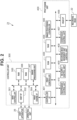
- Fig. 2 is a block diagram illustrating a control configuration in the recording apparatus 1.
- the control configuration of the control unit 21 includes a print engine unit 400 for controlling the recording apparatus 1 and a controller unit 300 for controlling the entire recording apparatus 1.
- a print controller 402 controls various types of mechanism of the print engine unit 400 based on instructions from a main controller 301 of the controller unit 300. The control configuration will be described in detail.
- the main controller 301 provided with a central processing unit (CPU) controls the entire recording apparatus 1 using a random access memory (RAM) 305 as a work area, based on programs and various types of parameter stored in a read-only memory (ROM) 306.
- a print job is input from the host apparatus 25 via a host interface (I/F) 302
- an image processing unit 307 performs predetermined image processing on received image data based on instructions from the main controller 301.
- the main controller 301 transmits the image data that has gone through the image processing to the print engine unit 400 via a print engine I/F 304.
- the recording apparatus 1 may acquire image data from the host apparatus 25 via wireless communication or wired communication, or may acquire image data from an external storage device (for example, a universal serial bus (USB) memory) connected to the recording apparatus 1.
- a communication method used for wireless communication or wired communication is not limited.
- Wireless Fidelity (Wi-Fi ® ) or Bluetooth ® can be applied as a communication method used for wireless communication.
- a USB is applicable as a communication method used for wired communication.
- the operation unit 24 is a mechanism for a user to input and output data to and from the recording apparatus 1.
- the user can set print modes and recognize information on the recording apparatus 1 via the operation unit 24.
- the print controller 402 provided with a CPU controls various types of mechanism of the recording apparatus 1 using a RAM 404 as a work area based on programs and various type of parameter stored in a ROM 403.
- the print controller 402 temporarily stores the commands or the image data in the RAM 404.
- the print controller 402 causes an image processing controller 405 to convert the stored image data into print data so that the recording heads 22 can use the print data for recording operation.
- the print controller 402 causes the recording heads 22 to perform recording operation based on the print data via a head IF 406.
- the print controller 402 conveys the sheet S by driving the various types of unit illustrated in Fig. 1 via a conveyance control unit 407.
- the print controller 402 drives the sheet feeding unit 2, the first dancer unit 3, the first conveying unit 4, the skew correcting unit 5, the detecting unit 6, the mark sensor unit 7, and the recording unit 8.
- the print controller 402 also drives the first scanner unit 9, the first drying unit 10, the second drying unit 11, the cooling unit 12, the second scanner unit 13, the second conveying unit 14, the second dancer unit 15, and the winding unit 16.
- the recording operation by the recording heads 22 is performed in conjunction with the conveyance operation of the sheet S, which performs a recording process on the sheet S.
- a recording head movement unit control unit 408 changes the position of the recording heads 22 depending on an operation state, such as a maintenance state and a recording state of the recording apparatus 1.
- An ink supply control unit 409 controls an ink supply unit (not illustrated) so that the pressure of the ink supplied to the recording heads 22 falls within an appropriate range.
- a maintenance control unit 410 controls the operation of the maintenance unit 17 when performing a maintenance operation on the recording heads 22.
- Fig. 3 is a perspective view of a conveyance unit housing 81 of the recording unit 8.
- a first positioning portion 811a, a second positioning portion 811b, and a third positioning portion 811c for positioning a recording head 22 at the printing position are disposed for each recording head 22 in the conveyance unit housing 81 of the recording unit 8.
- the first positioning portion 811a is disposed nearer the front side (e.g., apparatus front side) than the rear side in the sheet width direction (y direction) orthogonal to the sheet conveyance direction
- the second positioning portion 811b and the third positioning portion 811c are disposed nearer the rear side (e.g., apparatus rear side) than the front side.
- the first positioning portion 811a, the second positioning portion 811b, and the third positioning portion 811c are collectively referred to as recording head positioning portions 811.
- each of the recording heads 22 is supported by a head holder 26 as a support part, and is configured to move vertically (z direction) by movement of the head holder 26.
- a first pin 27a, a second pin 27b, and a third pin 27c as supported parts supported by the head holder 26 are arranged.
- the first pin 27a is a protruding portion that protrudes in the y direction from its end portion facing the apparatus front side in the longitudinal direction (y direction) of the recording head 22 that intersects the vertical movement direction of the recording head 22 and the sheet conveyance direction.
- the second pin 27b and the third pin 27c are each a protruding portion that protrudes in the y direction from its end portion facing the apparatus rear side in the longitudinal direction of the recording head 22.
- the first pin 27a, the second pin 27b, and the third pin 27c are respectively supported from below by a first hole, a second hole, and a third hole (not illustrated), which are arranged in the head holder 26, and thus the recording head 22 is axially supported with respect to the head holder 26.
- the recording head 22 is supported by the head holder 26 while being urged downward by urging members 51 (e.g., a first urging member 51a, a second urging member 51b, and a third urging member 51c) including compression springs disposed in the head holder 26.
- urging members 51 e.g., a first urging member 51a, a second urging member 51b, and a third urging member 51c
- the head holder 26 is moved vertically along a rail 29 for vertical movement in a frame 28 by a driving mechanism (not illustrated) in the head holder 26.
- the rail 29 and the not-illustrated driving mechanism function as a head vertical movement mechanism.
- Fig. 5 is a perspective view of each recording head 22.
- a plurality of nozzle plates 223 provided with a plurality of nozzles for ejecting ink are arranged in the longitudinal direction (sheet width direction, or y direction), and contact portions 221 for positioning the recording head 22 are provided at both ends of the recording head 22 in the longitudinal direction.
- a first contact portion 221a formed of a concave portion having a conical inclined surface is provided nearer the front side (e.g., apparatus front side) of the recording head 22 in the y direction than the rear side.
- a second contact portion 221b formed of a groove portion having two V-shaped flat surfaces and a third contact portion 221c formed of a flat surface portion are provided nearer the rear side (e.g., apparatus rear side) of the recording head 22 in the y direction than the front side.
- the first contact portion 221a, the second contact portion 221b, and the third contact portion 221c are collectively referred to as the contact portions 221.
- a guide portion 221d is disposed adjacent to the third contact portion 221c.
- the guide portion 221d prevents the third positioning portion 811c (refer to Fig. 7 ) from being displaced due to a slide of the recording head 22 that occurs when the third contact portion 221c and the third positioning portion 811c of the conveyance unit housing 81 come into contact with each other.
- the contact portions 221 are disposed such that a straight line connecting the centers of the first contact portion 221a and the second contact portion 221b and extending in the y direction is parallel to the arrangement of the plurality of nozzle plates 223 of the recording head 22.
- the third contact portion 221c is disposed at a position away from the second contact portion 221b in a direction (z direction) orthogonal to the y direction.
- Fig. 6 illustrates the plurality of recording heads 22 each positioned in contact with the corresponding recording head positioning portions 811 (refer to Fig. 7 ) provided on the conveyance unit housing 81, as viewed from the apparatus front side.
- the ink ejection surfaces of the plurality of recording heads 22 are positioned along the arc-shaped sheet conveyance path, inclined at different angles with respect to the horizontal direction (xy direction).
- the ink ejection surfaces of the plurality of recording heads 22 are classified into a first recording head 22a arranged to be downwardly inclined downstream in the sheet conveyance direction (x direction) in Fig. 6 , and a second recording head 22b arranged to be downwardly inclined upstream in the x direction.
- the present invention is not limited to a configuration in which the ink ejection surfaces of the recording heads 22 are inclined at angles with respect to the horizontal direction (xy direction).
- a configuration can also be employed in which the ink ejection surfaces are parallel to the horizontal direction.
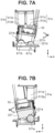
- Figs. 7A and 7A illustrate detailed configurations of both end portions of each recording head 22 in the longitudinal direction (y direction).
- Fig. 7A illustrates one recording head 22 as viewed from the rear side in the y direction (the apparatus rear side)
- Fig. 7B illustrates the recording head 22 as viewed from the front side in the y direction (e.g., the apparatus front side).
- the first urging member 51a is disposed above the first contact portion 221a, facing the first contact portion 221a of the recording head 22.
- the second urging member 51b is disposed above the second contact portion 221b, facing the second contact portion 221b of the recording head 22.
- the third urging member 51c is disposed above the third contact portion 221c, facing the third contact portion 221c of the recording head 22.
- the first urging member 51a, the second urging member 51b, and the third urging member 51c are collectively referred to as the urging members 51.
- the first contact portion 221a is in contact with the first positioning portion 811a.
- the second contact portion 221b is in contact with the second positioning portion 811b, and the third contact portion 221c is in contact with the third positioning portion 811c.
- the first urging member 51a includes a first base portion 511a, a first sliding portion 512a, and a spring (not illustrated), and the first sliding portion 512a is configured to be slidable with respect to the first base portion 511a.
- the second urging member 51b includes a second base portion 511b, a second sliding portion 512b, and a spring (not illustrated), and the second sliding portion 512b is configured to be slidable with respect to the second base portion 511b.
- the third urging member 51c includes a third base portion 511c, a third sliding portion 512c, and a spring (not illustrated), and the third sliding portion 512c is configured to be slidable with respect to the third base portion 511c.
- Each recording head 22 includes plates 52 arranged at both ends of the recording head 22 in the longitudinal direction (y direction) such that the plates 52 are in contact with the first sliding portion 512a, the second sliding portion 512b, and the third sliding portion 512c.
- the first sliding portion 512a, the second sliding portion 512b, and the third sliding portion 512c each have a spherical portion to come into contact with the corresponding plate 52, the spherical portion of which is configured to be slidable with respect to the plate 52.
- a moment M as illustrated in Fig. 7A, 7B is applied around the recording head positioning portion 811 so that the contact portion 221 reliably lands on the recording head positioning portion 811.
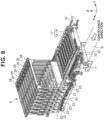
- Fig. 8 is a perspective view of a configuration of the recording unit 8 and the maintenance unit 17 in a recording state in which recording is performed by the recording heads 22, and Fig. 9 illustrates the configuration of Fig. 8 as viewed from the front side of the recording apparatus 1.
- Fig. 10 is a perspective view of a capping state in which the ink ejection surfaces of the recording heads 22 are protected by capping mechanisms to be described below, and
- Fig. 11 illustrates the configuration of Fig. 10 as viewed from the top side of the recording apparatus 1.
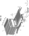
- Fig. 12 is a perspective view of a state during a cleaning operation for recovering ejection performance by the cleaning mechanisms to be described below
- Fig. 13 illustrates the configuration of Fig. 12 as viewed from the top side of the recording apparatus 1.
- the maintenance unit 17 includes the cap tray 18 on which the cap mechanisms 181 (refer to Fig. 13 ) are disposed and the cleaning tray 19 on which the cleaning mechanisms 191 (refer to Fig. 11 ) are disposed.
- the cap tray 18 and the cleaning tray 19 are configured to be individually movable in the width direction (x direction) of the recording apparatus 1 by a driving motor (not illustrated) along a plurality of rails 32 arranged on the housing of the recording apparatus 1.
- the rails 32 are each a guide mechanism that guides movement of the cap tray 18 and the cleaning tray 19 in the x direction with the end portions of the cap tray 18 and the cleaning tray 19 supported in the sheet width direction (y direction).
- Figs. 8 and 9 illustrate a recording state in which recording is performed on the sheet S by the recording heads 22, and the cap tray 18 and the cleaning tray 19 are positioned upstream of the recording unit 8 in the sheet conveyance direction.
- the cap tray 18 is positioned directly above the cleaning tray 19.
- the positions of the cap tray 18 and the cleaning tray 19 in the recording state are also referred to as standby positions.
- Figs. 10 and 11 illustrate a capping state in which the ink ejection surfaces of the recording heads 22 are capped by the cap mechanisms 181.
- the cap tray 18 is positioned directly below the recording heads 22 of the recording unit 8, and the cleaning tray 19 is positioned upstream of the recording unit 8 in the sheet conveyance direction.
- the cap tray 18 is moved along the rails 32 from its standby position to the capping position downstream in the sheet conveyance direction, and the cleaning tray 19 is positioned at its standby position.
- Figs. 12 and 13 illustrate a cleaning state in which the ink ejection surfaces of the recording heads 22 are cleaned by cleaning mechanisms 191.
- the cleaning tray 19 is positioned directly below the recording heads 22 of the recording unit 8, and the cap tray 18 is positioned upstream of the recording unit 8 in the sheet conveyance direction.
- the cleaning tray 19 is moved along the rails 32 from its standby position to a cleaning position downstream in the sheet conveyance direction, and the cap tray 18 is positioned at its standby position.
- the cap mechanisms 181 in the cap tray 18 each include a plurality of spherical recording head positioning portions 182 for positioning the recording head 22 with respect to the cap mechanism 181.
- the recording head positioning portions 182 are arranged at both ends of each cap mechanism 181 in the sheet width direction (y direction).
- a first recording head positioning portion 182a is arranged upstream (e.g., on the apparatus front side) in the y direction, and a second recording head positioning portion 182b and a third recording head positioning portion 182c are arranged downstream (e.g., on the apparatus rear side) in the y direction.
- the first recording head positioning portion 182a, the second recording head positioning portion 182b, and the third recording head positioning portion 182c are collectively referred to as the recording head positioning portions 182.
- the recording heads 22 and the cap mechanisms 181 are positioned such that the contact portions 221 disposed at both ends of the recording heads 22 in the longitudinal direction (y direction) are in contact with the recording head positioning portions 182 disposed at both ends of the cap mechanisms 181 in the y direction.
- the cleaning tray 19 is provided with a plurality of spherical recording head positioning portions 192 for positioning the recording head 22 with respect to the cleaning tray 19.
- the recording head positioning portions 192 are held by an upstream beam member 193a and a downstream beam member 193b, both of which extend in the x direction.
- the upstream beam member 193a and the downstream beam member 193b are disposed apart from each other in the sheet conveyance direction (x direction).
- the recording head positioning portions 192 are arranged at both ends of the cleaning tray 19 in the sheet width direction (x direction).
- a first recording head positioning portion 192a is disposed upstream (apparatus front side) in the y direction and is held by the upstream beam member 193a.
- a second recording head positioning portion 192b and a third recording head positioning portion 192c are disposed downstream (e.g., the apparatus rear side) in the y direction, and are held by the downstream beam member 193b.
- the first recording head positioning portion 192a, the second recording head positioning portion 192b, and the third recording head positioning portion 192c are collectively referred to as the recording head positioning portions 192.
- the recording heads 22 and the cleaning tray 19 are positioned such that the contact portions 221 disposed at both ends of each of the recording heads 22 in the longitudinal direction (y direction) are in contact with corresponding recording head positioning portions 192 disposed at both ends of the cleaning tray 19 in the y direction.
- the configuration for positioning with respect to the recording heads 22 is not limited to the configuration using the spherical positioning portions.
- a configuration in which the contact of a part of the recording heads 22 is made in the cleaning tray 19, or a configuration in which the recording heads are positioned using holes and pins respectively arranged on the cleaning tray 19 and the recording heads 22 may be employed.
- Fig. 14 is an enlarged view of a detailed configuration of each of the cleaning mechanisms 191 in the cleaning tray 19.
- the cleaning mechanism 191 includes a cleaning liquid applying unit 50 for applying a cleaning liquid to the nozzle plates 223 of the recording head 22, and a liquid removing unit (wiper unit) 60 as a wiper for removing (wiping) ink, paper dust, and the cleaning liquid on the recording heads 22.
- the cleaning mechanism 191 includes a suction unit 70 for applying a negative pressure to the nozzle plates 223 of the recording head 22 to remove ink adhering to the inside of the nozzles and bubbles in the ink flow paths.
- the suction unit 70 is connected to suction means (negative pressure generating means) (not illustrated).
- the cleaning tray 19 includes moving mechanisms (not illustrated) for moving the cleaning mechanisms 191 in the wiping direction D orthogonal to the sheet conveyance direction (refer to Fig. 11 ). While moving in the wiping direction D by the moving mechanisms, the cleaning mechanisms 191 remove ink and dust on the ink ejection surfaces of the recording heads 22 with the cleaning liquid applying unit 50, the liquid removing unit 60, and the suction unit 70, thereby recovering the ejection performance of the recording heads 22.
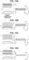
- Figs. 15A to 15D schematically illustrate an operation of positioning the recording heads 22 with respect to the cap tray 18.
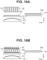
- Figs. 16A and 16B schematically illustrate an operation of positioning the recording heads 22 with respect to the cleaning tray 19.
- Fig. 15A illustrates a state in which the recording heads 22 are at a retracted position where the recording heads 22 are retracted upward from the conveyance unit housing 81. Further, the cap tray 18 and the cleaning tray 19 are at their standby positions, retracted upstream of the recording heads 22 in the sheet conveyance direction.
- Fig. 15B illustrates a state where the recording heads 22 are at the recording position at which an image is recorded on the sheet S.
- the recording heads 22 are moved downward from the retracted position illustrated in Fig. 15A by the head vertical movement mechanisms.
- the movement of the recording heads 22 is completed when the contact portions 221 of the recording heads 22 come into contact with the recording head positioning portions 811 of the conveyance unit housing 81 and the recording heads 22 are lowered to the recording position at which the recording heads 22 are positioned in orientations in which the recording heads 22 are inclined at predetermined angles.
- the conveyance unit housing 81 is formed in an arc shape, so that the recording heads 22 are to be lowered to different heights from each other.
- the head vertical movement mechanisms first lower the plurality of recording heads 22 to a predetermined position.
- the predetermined position is a position at which the head holders 26 (or the recording heads 22) are detected by a position detecting sensor (not illustrated). Thereafter, the head vertical movement mechanisms move (e.g., lower) the recording heads 22 by different distances from the predetermined position, thereby moving the recording heads 22 to different heights from each other with respect to the conveyance unit housing 81 formed in an arc shape.
- Each of the recording heads 22 is lowered from the predetermined position so as to be inclined at a predetermined angle with respect to a horizontal plane.
- Fig. 15C illustrates a state in which the recording heads 22 move from the recording position to the retracted position and the cap tray 18 moves from its standby position to the capping position, from the state illustrated in Fig. 15B .
- a capping operation on the ink ejection surfaces of the recording heads 22 is performed by the cap mechanisms 181.
- the recording heads 22 rise from the recording position to the retracted position, and then the cap tray 18 moves horizontally downstream in the sheet conveyance direction (x direction) to the capping position at which the cap tray 18 faces the ink ejection surfaces of the recording heads 22.
- Fig. 15D illustrates a state in which the recording heads 22 have moved from the retracted position to a position where the recording heads 22 are to be capped, from the state illustrated in Fig. 15C .
- Fig. 15D illustrates a capping state in which the recording heads 22 are capped by the cap mechanisms 181. Capping is performed when the recording heads 22 are lowered to the position where the recording heads 22 are to be capped and at which the contact portion 221 of each of the recording heads 22 is in contact with the corresponding recording head positioning portions 182 of the cap tray 18 and the recording head 22 is positioned.
- Fig. 16A illustrates a state in which the recording heads 22 are at the retracted position and the cleaning tray 19 has moved from its standby position to the cleaning position. If a nozzle of the recording heads 22 is clogged, causing an ink ejection failure, a cleaning operation (maintenance operation) is performed on the recording heads 22 by the cleaning mechanisms 191.
- the recording heads 22 When a cleaning operation is performed after a recording operation by the recording heads 22, first, the recording heads 22 are moved to the retracted position, and the cap tray 18 and the cleaning tray 19 are moved to their standby positions, which is the state illustrated in Fig. 15A . Thereafter, as illustrated in Fig. 16A , the cleaning tray 19 moves horizontally downstream in the sheet conveyance direction to the cleaning position at which the cleaning tray 19 faces the ink ejection surfaces of the recording heads 22.
- Fig. 16B illustrates a state in which the recording heads 22 have moved to a maintenance position.
- Fig. 16B illustrates a state in which the recording heads 22 are cleaned by the cleaning mechanisms 191. From the state illustrated in Fig. 16A , the recording heads 22 are lowered to the maintenance position at which the contact portion 221 of each of the recording heads 22 is in contact with the corresponding recording head positioning portions 192 of the cleaning tray 19 and the recording head 22 is positioned, and then cleaning is performed.
- Fig. 17 is a flowchart for the positioning operation of the recording heads 22 in a recording operation.
- the recording heads 22 are positioned at the position where the recording heads 22 are to be capped (e.g., a capped position), and are capped by the cap mechanisms 181.
- step S1002 the recording head movement unit control unit 408 drives a motor (not illustrated) for raising and lowering the head holders 26 to move (e.g., raise) the recording heads 22 from the capped position to the retracted position.
- step S1003 the maintenance control unit 410 drives a motor (not illustrated) for moving the cap tray 18.
- the cap tray 18 is moved horizontally in the sheet conveyance direction from the capping position to its standby position along the rails 32.
- step S1004 the recording head movement unit control unit 408 drives a motor (not illustrated) for vertically moving the head holders 26 and moves (e.g., lowers) the recording heads 22 from the retracted position to the recording position.
- step S1005 printing (e.g., recording) is performed on the sheet S by the recording heads 22.
- step S1006 the recording head movement unit control unit 408 then drives the motor (not illustrated) for vertically moving the head holders 26 and moves (e.g., raises) the recording heads 22 from the recording position to the retracted position.
- step S1007 the maintenance control unit 410 drives the motor (not illustrated) for moving the cap tray 18.
- the cap tray 18 is moved horizontally in the sheet conveyance direction from its standby position to the capping position along the rails 32.
- step S1008 the recording head movement unit control unit 408 drives the motor (not illustrated) for vertically moving the head holders 26 and moves (e.g., lowers) the recording heads 22 from the retracted position to the position where the recording heads 22 are to be capped, and then the ink ejection surfaces are capped by the cap mechanisms 181.
- the positioning operation of the recording heads 22 in the recording operation is completed.
- Fig. 18 is a flowchart for the positioning operation of the recording heads 22 in a cleaning operation.
- step S2001 the recording heads 22 are positioned at the position where the recording heads 22 are to be capped, and are capped by the cap mechanisms 181.
- step S2002 the recording head movement unit control unit 408 drives the motor (not illustrated) for vertically moving the head holders 26 and moves (e.g., raises) the recording heads 22 from the capped position to the retracted position.
- step S2003 the maintenance control unit 410 drives the motor (not illustrated) for moving the cap tray 18.
- the cap tray 18 is moved horizontally in the sheet conveyance direction from the capping position to its standby position along the rails 32.
- step S2004 the maintenance control unit 410 drives the motor (not illustrated) for moving the cleaning tray 19, and the cleaning tray 19 then is moved horizontally in the sheet conveyance direction along the rails 32. By this horizontal movement, the cleaning tray 19 is moved to the cleaning position facing the ink ejection surfaces of the recording heads 22.
- step S2005 the recording head movement unit control unit 408 drives the motor (not illustrated) for vertically moving the head holders 26 and moves (e.g., lowers) the recording heads 22 from the retracted position to the maintenance position.
- step S2006 a cleaning operation is performed on the recording heads 22 by the cleaning mechanisms 191.
- step S2007 the recording head movement unit control unit 408 drives the motor (not illustrated) for vertically moving the head holders 26, and moves (e.g., raises) the recording heads 22 from the maintenance position to the retracted position.
- step S2008 the maintenance control unit 410 drives the motor (not illustrated) for moving the cleaning tray 19, and the cleaning tray 19 is moved horizontally in the sheet conveyance direction along the rails 32, thereby moving from the cleaning position to its standby position.
- step S2009 the maintenance control unit 410 drives the motor (not illustrated) for moving the cap tray 18, and the cap tray 18 is moved horizontally in the sheet conveyance direction along the rails 32, thereby moving from its standby position to the capping position.
- step S2010 the recording head movement unit control unit 408 drives the motor (not illustrated) for vertically moving the head holders 26, and moves (e.g., lowers) the recording heads 22 from the retracted position to the position where the recording heads 22 are to be capped, thereby completing the positioning operation of the recording heads in the cleaning operation.
- the cap tray 18 alone of the maintenance unit 17 moves horizontally in the sheet conveyance direction to the capping position facing the ink ejection surfaces of the recording heads 22.
- the cleaning tray 19 of the maintenance unit 17 remains at its standby position, retracted upstream in the sheet conveyance direction with respect to the recording heads 22.
- the cleaning tray 19 alone of the maintenance unit 17 moves horizontally in the sheet conveyance direction to the cleaning position facing the ink ejection surfaces of the recording heads 22.
- the cap tray 18 of the maintenance unit 17 remains at its standby position, retracted upstream in the sheet conveyance direction with respect to the recording heads 22.
- the cap tray 18 and the cleaning tray 19 are configured to be independently movable, and the cap tray 18 and the cleaning tray 19 are configured to overlap each other in the z direction. In other words, the cap tray 18 and the cleaning tray 19 are disposed at different levels from each other in the z-direction.
- the cap tray 18 is disposed directly above the cleaning tray 19 in the maintenance unit 17, but the cleaning tray 19 may be disposed directly above the cap tray 18.
- the configuration in this case provides a smaller size of the maintenance unit 17 in the apparatus rear direction.
- the recording heads 22 is configured to move in the vertical direction (z direction) so as to move to the retracted position, the position where the recording heads 22 are to be capped, the maintenance position, and the recording position in this order from the top.
- the plurality of recording heads 22 do not move in the rear direction of the recording apparatus 1, providing a compact size of and allowing saving the space for the recording apparatus 1 in its rear direction.
- both the cap tray 18 and the cleaning tray 19 according to the present embodiment are configured to be disposed on the conveyance path of the sheet S and move horizontally in the sheet conveyance direction, and are configured not to move in the sheet width direction (y direction). This configuration saves the space for the recording apparatus 1 in its rear direction (y direction in the present embodiment).
- a second embodiment will be described.
- the configuration has been described in which the cap tray 18 and the cleaning tray 19 of the maintenance unit 17 are retracted from under the recording heads 22 to the upstream side in the sheet conveyance direction.
- a cap tray 1018 is retracted to its standby position upstream of the recording heads 22 in the sheet conveyance direction
- a cleaning tray 1019 is retracted to its standby position downstream of the recording heads 22 in the sheet conveyance direction.
- cap tray 1018 and the cleaning tray 1019 positioned at their standby positions, space is made over both of them. This space allows an operator to clean a cap mechanism 1182 and a cleaning mechanism 1192, for example.
- a configuration can have the same effect in which the cap tray 1018 is retracted downstream of the recording heads 22 in the sheet conveyance direction and the cleaning tray 1019 is retracted upstream of the recording heads 22 in the sheet conveyance direction.
- FIG. 20A is a schematic top view of the main part including a recording unit 2008 of the recording apparatus 1 in a state where the recording heads 22 according to the present embodiment are capped by cap mechanisms 2182.
- Fig. 20B is a front view of the recording unit 2008 illustrated in Fig. 20A .
- the cleaning tray 2019 includes a cleaning mechanism 2191 and a plurality of recording head positioning units 2192.
- both the cap tray 2018 and the cleaning tray 2019 according to the present embodiment are configured to horizontally move in the sheet width direction along a plurality of rails 2032 and not to move in the sheet conveyance direction. Unlike the first embodiment, this configuration allows saving space in the lateral width direction (x direction) of the recording apparatus 1.
Landscapes
- Ink Jet (AREA)
- Engineering & Computer Science (AREA)
- Environmental & Geological Engineering (AREA)
Abstract
Description
- The present invention relates to a liquid ejection apparatus for ejecting liquid.
- Inkjet recording apparatuses are a type of liquid ejection apparatus. They each include a recording head provided with nozzles that each contain ink that can lose moisture, causing its thickening or solidification. Further, paper dust or air bubbles can enter a nozzle of the recording head, resulting in an ejection failure. To address those issues, inkjet recording apparatuses generally perform cleaning of their recording heads.
-
Japanese Patent Application Laid-Open No. 2011-240550 Japanese Patent Application Laid-Open No. 2011-240550 - However, the arrangement of the cleaning mechanism and the cap side by side in the sheet width direction, and configured to move integrally, as described in
Japanese Patent Application Laid-Open No. 2011-240550 - In view of the above issues, the present invention is directed to providing a liquid ejection apparatus to prevent an apparatus from being large in size.
- According to a first aspect of the present invention, there is provided a liquid ejection apparatus as specified in claims 1 to 15.
- Further features of the present invention will become apparent from the following description of embodiments with reference to the attached drawings.
-
-
Fig. 1 is a schematic view of the internal configuration of a recording apparatus according to a first embodiment. -
Fig. 2 is a control configuration diagram of the recording apparatus according to the first embodiment. -
Fig. 3 is a perspective view of a conveyance unit housing of a recording unit according to the first embodiment. -
Fig. 4 is a perspective view of a vertical movement mechanism of a recording head according to the first embodiment. -
Fig. 5 is a perspective view of the recording head according to the first embodiment. -
Fig. 6 is a front view of the periphery of the recording head according to the first embodiment. -
Figs 7A and 7B illustrate a detailed configuration of both end portions of the recording head according to the first embodiment. -
Fig. 8 is a perspective view of a configuration of the recording unit and a maintenance unit according to the first embodiment. -
Fig. 9 is a front view of the configuration of the recording unit and the maintenance unit according to the first embodiment. -
Fig. 10 is a perspective view of the configuration of the recording unit and the maintenance unit according to the first embodiment. -
Fig. 11 is a top view of the configuration of the recording unit and the maintenance unit according to the first embodiment. -
Fig. 12 is a perspective view of the configuration of the recording unit and the maintenance unit according to the first embodiment. -
Fig. 13 is a top view of the configuration of the recording unit and the maintenance unit according to the first embodiment. -
Fig. 14 is an enlarged view of the configuration of a cleaning mechanism according to the first embodiment. -
Figs. 15A to 15D illustrate a positioning operation of the recording head according to the first embodiment. -
Figs. 16A and 16B illustrate the positioning operation of the recording head according to the first embodiment. -
Fig. 17 is a flowchart for a positioning operation of the recording head during recording according to the first embodiment. -
Fig. 18 is a flowchart for a positioning operation of the recording head during cleaning according to the first embodiment. -
Fig. 19 illustrates a positioning operation of a recording head according to a second embodiment. -
Figs. 20A and 20B illustrate a positioning operation of a recording head according to a third embodiment. - Hereinafter, a first embodiment of the present invention will be described with reference to the drawings. The following embodiments are not intended to limit the present invention, and not all combinations of features described in the embodiments are used as solving means of the present invention. In addition, for example, relative arrangements and shapes of constituent elements described in the embodiments are merely examples, and the scope of the present invention is not intended to be limited thereto. In each drawing, arrows x and y indicate horizontal directions orthogonal to each other, and an arrow z indicates a vertical direction (gravity direction).
- It should be understood that "recording" is not limited to the case of forming significant information such as characters and graphics. The term "recording" broadly includes a case where, for example, an image, a design, or a pattern is formed on a recording medium or a case where a medium is processed regardless of whether the recording is significant or insignificant, and it does not matter whether the recording is actualized so as to be visually perceived by a human or not. In the present embodiment, a "recording medium" is assumed to be a sheet of paper, but may be, for example, a cloth or a plastic film.
-
Fig. 1 is a schematic cross-sectional view of the internal configuration of a recording apparatus 1 as a liquid ejection apparatus according to the first embodiment of the present invention. In the present embodiment, an x direction indicates the width direction of the recording apparatus 1, a y direction indicates the rear direction of the recording apparatus 1, and a z direction indicates the height direction of the recording apparatus 1. - The recording apparatus 1 includes a
sheet feeding unit 2, afirst dancer unit 3, a first conveying unit 4, askew correcting unit 5, a detecting unit 6, amark sensor unit 7, and arecording unit 8. The recording apparatus 1 further includes afirst scanner unit 9, afirst drying unit 10, asecond drying unit 11, acooling unit 12, asecond scanner unit 13, asecond conveying unit 14, asecond dancer unit 15, awinding unit 16, and amaintenance unit 17. A sheet S (e.g., a recording medium) is conveyed along a sheet conveyance path indicated by a solid line inFig. 1 , and is processed by the above-described units. - The
sheet feeding unit 2 is configured to hold and store a continuous sheet wound in a roll shape and to draw out and feed the sheet S. The number of storable rolls is not limited to one. For example, two or three or more rolls may be stored. The sheet S may be selectively pulled out and supplied from one of the plurality of stored rolls. - The
first dancer unit 3 is a unit for applying a constant tension to the sheet S between thesheet feeding unit 2 and the first conveying unit 4. A sheet tension is applied to thefirst dancer unit 3 by a tension applying unit (not illustrated). - The first conveying unit 4 is a unit for conveying the sheet S toward the
skew correcting unit 5, the detecting unit 6, themark sensor unit 7, therecording unit 8, thefirst scanner unit 9, thefirst drying unit 10, thesecond drying unit 11, thecooling unit 12, and thesecond scanner unit 13, all of which are arranged in this order along the sheet conveyance path. The first conveying unit 4 also serves as a unit for applying tension to the sheet S between the first conveying unit 4 and thesecond conveying unit 14. The first conveying unit 4 is rotated by driving a motor (not illustrated), and performs tension conveyance of the sheet S together with thesecond conveying unit 14. - The
skew correcting unit 5 is a unit for correcting a skew of the sheet S in the conveyance of the sheet S. Theskew correcting unit 5 includes askew correcting roller 5a and a skew detecting sensor (not illustrated) for detecting a skew of the sheet S. Theskew correcting roller 5a can change an inclination of the sheet S by a motor (not illustrated), and corrects a skew of the sheet S based on a detection result of the skew detecting sensor. At this time, winding the sheet S around theskew correcting roller 5a heightens the effect of skew correction. - The detecting unit 6 is a unit for detecting a tension applied to the sheet S when the sheet S is tension-conveyed between the first conveying unit 4 and the second conveying
unit 14. Further, the detecting unit 6 is a unit including a mechanism for detecting a conveyance speed of the sheet S in order to control an image forming timing (ejection timing) in therecording unit 8. - The
mark sensor unit 7 is a unit for detecting marks printed on the sheet S in advance in order to control the image forming timing of therecording unit 8. - The
recording unit 8 is a sheet processing unit for performing a recording process by forming an image as an example by ink as a recording liquid being ejected by at least onerecording head 22, or ejection head, (e.g., a plurality of recording heads 22) from above onto the sheet S being conveyed. - The sheet conveyance path in the
recording unit 8 is formed by a plurality ofguide rollers 23 arranged in an arc shape which is convex upward (i.e., a straight line drawn between two points of the arc shape is always below the arc shape). A constant tension applied to the sheet S by the first conveying unit 4 and the second conveyingunit 14 forms a clearance (e.g., interval) of a predetermined distance between the recording heads 22 and the sheet S. - The recording apparatus 1 is an inkjet recording apparatus in which the plurality of recording heads 22 are arranged in the x direction. In the present embodiment, in addition to the recording heads 22 for four colors, black (Bk), yellow (Y), magenta (M), and cyan ©, a total of eight recording heads 22 including the recording heads 22 for a reaction liquid and three special colors are provided so that one recording head is assigned to each color of ink, and the other recording head to the reaction liquid. Further, the recording heads 22 are each a full-line recording head in which nozzles (e.g., ejection ports) are arrayed over a length corresponding to the width direction of the sheet S. The number of ink colors and a reaction liquid and the number of recording heads 22 are not limited to eight. The ink of each color is supplied to the
corresponding recording head 22 from its ink tank serving as a liquid container (not illustrated) through a supply path of, for example, a tube. - An ejecting element is disposed in each nozzle of the recording heads 22. An ejecting element is, for example, an element which ejects ink in its nozzle by pressure generated in its nozzle, and can use a technique for an inkjet recording head of known inkjet printers. Examples of the ejecting element include an element that ejects ink by film boiling the ink with an electrothermal transducer to create a bubble, an element that ejects ink by an electromechanical transducer, an element that ejects ink using static electricity, and a micro-electro-mechanical systems (MEMS) element. From the viewpoint of high-speed and high-density recording, an ejecting element using an electrothermal transducer can be used.
- The
first scanner unit 9 is a unit for reading an image formed on the sheet S by therecording unit 8, detecting the deviation and the density of the image, and correcting the recording process by therecording unit 8. After passing through thefirst scanner unit 9, the sheet S is conveyed in the sheet conveyance direction, which is reversed by aguide roller 31. - The
first drying unit 10 and thesecond drying unit 11 are units that reduce the moisture contained in the ink applied onto the sheet S by therecording unit 8 and increase the fixability of the ink to the sheet S. Thesecond drying unit 11 is disposed downstream of thefirst drying unit 10 in the sheet conveyance direction. Thefirst drying unit 10 and thesecond drying unit 11 dry the ink applied to the sheet S by applying hot air to at least the ink applied surface (e.g., recording surface) of the passing sheet S. As the drying method, in addition to the method of applying hot air, a method of irradiating the surface of the sheet S with electromagnetic waves (such as ultraviolet rays or infrared rays), a method of conduction heat transfer performed by contact with a heating element, or a combination of a plurality of these methods may be adopted. - The
guide roller 31 is a roller that winds the back surface of the recording surface of the sheet S at a constant winding angle in order to prevent the hot air in thefirst drying unit 10 from affecting the recording process in therecording unit 8. Twoguide rollers 31 according to the present embodiment are disposed between thefirst scanner unit 9 and thefirst drying unit 10. Thus, the sheet S is turned around in the vertical direction of the recording apparatus 1 and is conveyed such that the sheet conveyance direction is reversed. In the present embodiment, thefirst drying unit 10 is disposed under therecording unit 8, and thesecond drying unit 11 is disposed under the detecting unit 6 and themark sensor unit 7. - The cooling
unit 12 cools the sheet S on which the ink is fixed by thefirst drying unit 10 and thesecond drying unit 11. The coolingunit 12 solidifies the softened ink and reduces a change in temperature of the sheet S in the downstream process of the recording apparatus 1. Inside the coolingunit 12, air (cold air) having a temperature lower than that of the sheet S passing through the coolingunit 12 is applied to at least the recording surface of the passing sheet S to cool the recording surface of the sheet S. The cooling method is not limited to the method of applying air, and a method of conduction heat transfer performed by contact with a heat dissipation member may be adopted, or a plurality of these methods may be combined. - The
second scanner unit 13 is a unit for reading a test image formed on the sheet S by therecording unit 8, detecting the deviation and/or the density of the image, and for example, correcting an ejection timing based on the detection result, before a recording operation is performed by receiving a recording instruction from a user. - The second conveying
unit 14 is a unit for conveying the sheet S with a tension applied to the sheet S between the first conveying unit 4 and the second conveyingunit 14, and adjusting the tension to the sheet S. The second conveyingunit 14 is rotated by being driven by a motor (not illustrated), and adjusts the tension to the sheet S by a drive-coupled clutch (not illustrated) controlling torque based on a tension value detected by the detecting unit 6. - As a configuration for adjusting the tension to the sheet S, a configuration for controlling the speed of the second conveying
unit 14 by the detecting unit 6 may be added. In this case, the recording apparatus 1 employ two methods as the tension control method: a torque control method for controlling a torque value transmitted from the clutch and a speed control method for controlling the roller speed of the second conveyingunit 14. These two methods can be switched as the tension control method suited to a purpose, or both methods can be used at the same time. - The
second dancer unit 15 is a unit for applying a constant sheet tension between the second conveyingunit 14 and the windingunit 16. A sheet tension is applied to thesecond dancer unit 15 by a tension applying unit (not illustrated). - The winding
unit 16 is a unit for winding the sheet S through the recording process on its winding core. The number of rollers that can take up the sheet S is not limited to one, and a configuration may be employed in which the sheet S is taken up on one of two or three or more winding cores switched selectively. Further, instead of a configuration of winding the sheet S on a winding core, a configuration may be employed in which the continuous sheet is cut using a cutter and the cut sheet S is discharged and stacked, based on a process after recording. Furthermore, the present invention can also be applied to a configuration in which recording is performed by feeding a sheet-shaped recording medium cut in advance, instead of the roll-shaped sheet S. - The
maintenance unit 17 is a unit including acap tray 18 on whichcap mechanisms 181 for protecting the ink ejection surfaces of the recording heads 22 are disposed (as shown, for example, inFig. 13 , and a cleaningtray 19 on whichcleaning mechanisms 191 for recovering the ejection capability of the recording heads 22 are disposed (as shown, for example, inFig. 11 ). The ink ejection surfaces are ejection port surfaces (e.g., nozzle surfaces) on which a plurality of ejection ports for discharging ink are arranged in the recording heads 22. Themaintenance unit 17 will be described in detail below. - A
control unit 21 is a unit for controlling the units of the entire recording apparatus 1. Thecontrol unit 21 includes a controller including a CPU, a storage device, and various types of control unit, an external interface, and anoperation unit 24 through which a user performs input and output operations. The operation of the recording apparatus 1 is controlled based on commands from the controller or ahost apparatus 25 of, for example, a host computer connected to the controller via the external interface. -
Fig. 2 is a block diagram illustrating a control configuration in the recording apparatus 1. The control configuration of thecontrol unit 21 includes aprint engine unit 400 for controlling the recording apparatus 1 and acontroller unit 300 for controlling the entire recording apparatus 1. Aprint controller 402 controls various types of mechanism of theprint engine unit 400 based on instructions from amain controller 301 of thecontroller unit 300. The control configuration will be described in detail. - In the
controller unit 300, themain controller 301 provided with a central processing unit (CPU) controls the entire recording apparatus 1 using a random access memory (RAM) 305 as a work area, based on programs and various types of parameter stored in a read-only memory (ROM) 306. For example, when a print job is input from thehost apparatus 25 via a host interface (I/F) 302, animage processing unit 307 performs predetermined image processing on received image data based on instructions from themain controller 301. Themain controller 301 transmits the image data that has gone through the image processing to theprint engine unit 400 via a print engine I/F 304. - The recording apparatus 1 may acquire image data from the
host apparatus 25 via wireless communication or wired communication, or may acquire image data from an external storage device (for example, a universal serial bus (USB) memory) connected to the recording apparatus 1. A communication method used for wireless communication or wired communication is not limited. For example, Wireless Fidelity (Wi-Fi®) or Bluetooth® can be applied as a communication method used for wireless communication. In addition, for example, a USB is applicable as a communication method used for wired communication. - The
operation unit 24 is a mechanism for a user to input and output data to and from the recording apparatus 1. The user can set print modes and recognize information on the recording apparatus 1 via theoperation unit 24. - In the
print engine unit 400, theprint controller 402 provided with a CPU controls various types of mechanism of the recording apparatus 1 using aRAM 404 as a work area based on programs and various type of parameter stored in aROM 403. When various types of command or image data are received via a controller I/F 401, theprint controller 402 temporarily stores the commands or the image data in theRAM 404. - The
print controller 402 causes animage processing controller 405 to convert the stored image data into print data so that the recording heads 22 can use the print data for recording operation. When the print data is generated, theprint controller 402 causes the recording heads 22 to perform recording operation based on the print data via a head IF 406. - In the mean time, the
print controller 402 conveys the sheet S by driving the various types of unit illustrated inFig. 1 via aconveyance control unit 407. In other words, theprint controller 402 drives thesheet feeding unit 2, thefirst dancer unit 3, the first conveying unit 4, theskew correcting unit 5, the detecting unit 6, themark sensor unit 7, and therecording unit 8. Theprint controller 402 also drives thefirst scanner unit 9, thefirst drying unit 10, thesecond drying unit 11, the coolingunit 12, thesecond scanner unit 13, the second conveyingunit 14, thesecond dancer unit 15, and the windingunit 16. Based on instructions from theprint controller 402, the recording operation by the recording heads 22 is performed in conjunction with the conveyance operation of the sheet S, which performs a recording process on the sheet S. - A recording head movement
unit control unit 408 changes the position of the recording heads 22 depending on an operation state, such as a maintenance state and a recording state of the recording apparatus 1. An inksupply control unit 409 controls an ink supply unit (not illustrated) so that the pressure of the ink supplied to the recording heads 22 falls within an appropriate range. Amaintenance control unit 410 controls the operation of themaintenance unit 17 when performing a maintenance operation on the recording heads 22. -
Fig. 3 is a perspective view of aconveyance unit housing 81 of therecording unit 8. As illustrated inFig. 3 , afirst positioning portion 811a, asecond positioning portion 811b, and athird positioning portion 811c for positioning arecording head 22 at the printing position (e.g., recording position) are disposed for eachrecording head 22 in theconveyance unit housing 81 of therecording unit 8. For onerecording head 22, thefirst positioning portion 811a is disposed nearer the front side (e.g., apparatus front side) than the rear side in the sheet width direction (y direction) orthogonal to the sheet conveyance direction, and thesecond positioning portion 811b and thethird positioning portion 811c are disposed nearer the rear side (e.g., apparatus rear side) than the front side. Thefirst positioning portion 811a, thesecond positioning portion 811b, and thethird positioning portion 811c are collectively referred to as recordinghead positioning portions 811. - As illustrated in
Fig. 4 , each of the recording heads 22 is supported by ahead holder 26 as a support part, and is configured to move vertically (z direction) by movement of thehead holder 26. In therecording head 22, afirst pin 27a, asecond pin 27b, and athird pin 27c as supported parts supported by thehead holder 26 are arranged. - The
first pin 27a is a protruding portion that protrudes in the y direction from its end portion facing the apparatus front side in the longitudinal direction (y direction) of therecording head 22 that intersects the vertical movement direction of therecording head 22 and the sheet conveyance direction. Thesecond pin 27b and thethird pin 27c are each a protruding portion that protrudes in the y direction from its end portion facing the apparatus rear side in the longitudinal direction of therecording head 22. Thefirst pin 27a, thesecond pin 27b, and thethird pin 27c are respectively supported from below by a first hole, a second hole, and a third hole (not illustrated), which are arranged in thehead holder 26, and thus therecording head 22 is axially supported with respect to thehead holder 26. - Further, the
recording head 22 is supported by thehead holder 26 while being urged downward by urging members 51 (e.g., a first urgingmember 51a, asecond urging member 51b, and athird urging member 51c) including compression springs disposed in thehead holder 26. Thehead holder 26 is moved vertically along arail 29 for vertical movement in aframe 28 by a driving mechanism (not illustrated) in thehead holder 26. In short, therail 29 and the not-illustrated driving mechanism function as a head vertical movement mechanism. -
Fig. 5 is a perspective view of eachrecording head 22. As illustrated inFig. 5 , in therecording head 22, a plurality ofnozzle plates 223 provided with a plurality of nozzles for ejecting ink are arranged in the longitudinal direction (sheet width direction, or y direction), andcontact portions 221 for positioning therecording head 22 are provided at both ends of therecording head 22 in the longitudinal direction. - Considering the
contact portions 221 in detail, afirst contact portion 221a formed of a concave portion having a conical inclined surface is provided nearer the front side (e.g., apparatus front side) of therecording head 22 in the y direction than the rear side. In addition, asecond contact portion 221b formed of a groove portion having two V-shaped flat surfaces and athird contact portion 221c formed of a flat surface portion are provided nearer the rear side (e.g., apparatus rear side) of therecording head 22 in the y direction than the front side. In this embodiment, thefirst contact portion 221a, thesecond contact portion 221b, and thethird contact portion 221c are collectively referred to as thecontact portions 221. - A
guide portion 221d is disposed adjacent to thethird contact portion 221c. Theguide portion 221d prevents thethird positioning portion 811c (refer toFig. 7 ) from being displaced due to a slide of therecording head 22 that occurs when thethird contact portion 221c and thethird positioning portion 811c of theconveyance unit housing 81 come into contact with each other. - The
contact portions 221 are disposed such that a straight line connecting the centers of thefirst contact portion 221a and thesecond contact portion 221b and extending in the y direction is parallel to the arrangement of the plurality ofnozzle plates 223 of therecording head 22. Thethird contact portion 221c is disposed at a position away from thesecond contact portion 221b in a direction (z direction) orthogonal to the y direction. -
Fig. 6 illustrates the plurality of recording heads 22 each positioned in contact with the corresponding recording head positioning portions 811 (refer toFig. 7 ) provided on theconveyance unit housing 81, as viewed from the apparatus front side. In the present embodiment, the ink ejection surfaces of the plurality of recording heads 22 are positioned along the arc-shaped sheet conveyance path, inclined at different angles with respect to the horizontal direction (xy direction). The ink ejection surfaces of the plurality of recording heads 22 are classified into afirst recording head 22a arranged to be downwardly inclined downstream in the sheet conveyance direction (x direction) inFig. 6 , and asecond recording head 22b arranged to be downwardly inclined upstream in the x direction. The present invention is not limited to a configuration in which the ink ejection surfaces of the recording heads 22 are inclined at angles with respect to the horizontal direction (xy direction). A configuration can also be employed in which the ink ejection surfaces are parallel to the horizontal direction. -
Figs. 7A and 7A illustrate detailed configurations of both end portions of eachrecording head 22 in the longitudinal direction (y direction).Fig. 7A illustrates onerecording head 22 as viewed from the rear side in the y direction (the apparatus rear side), andFig. 7B illustrates therecording head 22 as viewed from the front side in the y direction (e.g., the apparatus front side). Thefirst urging member 51a is disposed above thefirst contact portion 221a, facing thefirst contact portion 221a of therecording head 22. Thesecond urging member 51b is disposed above thesecond contact portion 221b, facing thesecond contact portion 221b of therecording head 22. Thethird urging member 51c is disposed above thethird contact portion 221c, facing thethird contact portion 221c of therecording head 22. Thefirst urging member 51a, thesecond urging member 51b, and the third urgingmember 51c are collectively referred to as the urging members 51. - With the
recording head 22 positioned in theconveyance unit housing 81, thefirst contact portion 221a is in contact with thefirst positioning portion 811a. Thesecond contact portion 221b is in contact with thesecond positioning portion 811b, and thethird contact portion 221c is in contact with thethird positioning portion 811c. - The
first urging member 51a includes afirst base portion 511a, a first slidingportion 512a, and a spring (not illustrated), and the first slidingportion 512a is configured to be slidable with respect to thefirst base portion 511a. Similarly, thesecond urging member 51b includes asecond base portion 511b, a second slidingportion 512b, and a spring (not illustrated), and the second slidingportion 512b is configured to be slidable with respect to thesecond base portion 511b. Thethird urging member 51c includes athird base portion 511c, a third slidingportion 512c, and a spring (not illustrated), and the third slidingportion 512c is configured to be slidable with respect to thethird base portion 511c. - Each
recording head 22 includesplates 52 arranged at both ends of therecording head 22 in the longitudinal direction (y direction) such that theplates 52 are in contact with the first slidingportion 512a, the second slidingportion 512b, and the third slidingportion 512c. The first slidingportion 512a, the second slidingportion 512b, and the third slidingportion 512c each have a spherical portion to come into contact with thecorresponding plate 52, the spherical portion of which is configured to be slidable with respect to theplate 52. At each urging position of the urgingmembers recording head 22 in contact with thehead holder 26, a moment M as illustrated inFig. 7A, 7B is applied around the recordinghead positioning portion 811 so that thecontact portion 221 reliably lands on the recordinghead positioning portion 811. - A configuration of the
maintenance unit 17 of the recording apparatus 1 will now be described with reference toFigs. 8 to 13 . -
Fig. 8 is a perspective view of a configuration of therecording unit 8 and themaintenance unit 17 in a recording state in which recording is performed by the recording heads 22, andFig. 9 illustrates the configuration ofFig. 8 as viewed from the front side of the recording apparatus 1.Fig. 10 is a perspective view of a capping state in which the ink ejection surfaces of the recording heads 22 are protected by capping mechanisms to be described below, andFig. 11 illustrates the configuration ofFig. 10 as viewed from the top side of the recording apparatus 1.Fig. 12 is a perspective view of a state during a cleaning operation for recovering ejection performance by the cleaning mechanisms to be described below, andFig. 13 illustrates the configuration ofFig. 12 as viewed from the top side of the recording apparatus 1. - As illustrated in
Figs. 8 to 11 , themaintenance unit 17 includes thecap tray 18 on which the cap mechanisms 181 (refer toFig. 13 ) are disposed and the cleaningtray 19 on which the cleaning mechanisms 191 (refer toFig. 11 ) are disposed. Thecap tray 18 and the cleaningtray 19 are configured to be individually movable in the width direction (x direction) of the recording apparatus 1 by a driving motor (not illustrated) along a plurality ofrails 32 arranged on the housing of the recording apparatus 1. Therails 32 are each a guide mechanism that guides movement of thecap tray 18 and the cleaningtray 19 in the x direction with the end portions of thecap tray 18 and the cleaningtray 19 supported in the sheet width direction (y direction). -
Figs. 8 and9 illustrate a recording state in which recording is performed on the sheet S by the recording heads 22, and thecap tray 18 and the cleaningtray 19 are positioned upstream of therecording unit 8 in the sheet conveyance direction. In the recording state, thecap tray 18 is positioned directly above the cleaningtray 19. The positions of thecap tray 18 and the cleaningtray 19 in the recording state are also referred to as standby positions. -
Figs. 10 and11 illustrate a capping state in which the ink ejection surfaces of the recording heads 22 are capped by thecap mechanisms 181. In the capping state, thecap tray 18 is positioned directly below the recording heads 22 of therecording unit 8, and the cleaningtray 19 is positioned upstream of therecording unit 8 in the sheet conveyance direction. In other words, thecap tray 18 is moved along therails 32 from its standby position to the capping position downstream in the sheet conveyance direction, and the cleaningtray 19 is positioned at its standby position. -
Figs. 12 and13 illustrate a cleaning state in which the ink ejection surfaces of the recording heads 22 are cleaned by cleaningmechanisms 191. In the cleaning state, the cleaningtray 19 is positioned directly below the recording heads 22 of therecording unit 8, and thecap tray 18 is positioned upstream of therecording unit 8 in the sheet conveyance direction. In other words, the cleaningtray 19 is moved along therails 32 from its standby position to a cleaning position downstream in the sheet conveyance direction, and thecap tray 18 is positioned at its standby position. - As illustrated in
Fig. 13 , thecap mechanisms 181 in thecap tray 18 each include a plurality of spherical recordinghead positioning portions 182 for positioning therecording head 22 with respect to thecap mechanism 181. The recordinghead positioning portions 182 are arranged at both ends of eachcap mechanism 181 in the sheet width direction (y direction). - A first recording
head positioning portion 182a is arranged upstream (e.g., on the apparatus front side) in the y direction, and a second recordinghead positioning portion 182b and a third recording head positioning portion 182c are arranged downstream (e.g., on the apparatus rear side) in the y direction. The first recordinghead positioning portion 182a, the second recordinghead positioning portion 182b, and the third recording head positioning portion 182c are collectively referred to as the recordinghead positioning portions 182. - The recording heads 22 and the
cap mechanisms 181 are positioned such that thecontact portions 221 disposed at both ends of the recording heads 22 in the longitudinal direction (y direction) are in contact with the recordinghead positioning portions 182 disposed at both ends of thecap mechanisms 181 in the y direction. - Further, as illustrated in
Fig. 11 , the cleaningtray 19 is provided with a plurality of spherical recordinghead positioning portions 192 for positioning therecording head 22 with respect to the cleaningtray 19. The recordinghead positioning portions 192 are held by anupstream beam member 193a and adownstream beam member 193b, both of which extend in the x direction. Theupstream beam member 193a and thedownstream beam member 193b are disposed apart from each other in the sheet conveyance direction (x direction). - The recording
head positioning portions 192 are arranged at both ends of the cleaningtray 19 in the sheet width direction (x direction). A first recordinghead positioning portion 192a is disposed upstream (apparatus front side) in the y direction and is held by theupstream beam member 193a. In addition, a second recordinghead positioning portion 192b and a third recordinghead positioning portion 192c are disposed downstream (e.g., the apparatus rear side) in the y direction, and are held by thedownstream beam member 193b. The first recordinghead positioning portion 192a, the second recordinghead positioning portion 192b, and the third recordinghead positioning portion 192c are collectively referred to as the recordinghead positioning portions 192. - The recording heads 22 and the cleaning
tray 19 are positioned such that thecontact portions 221 disposed at both ends of each of the recording heads 22 in the longitudinal direction (y direction) are in contact with corresponding recordinghead positioning portions 192 disposed at both ends of the cleaningtray 19 in the y direction. - The configuration for positioning with respect to the recording heads 22 is not limited to the configuration using the spherical positioning portions. For example, a configuration in which the contact of a part of the recording heads 22 is made in the cleaning
tray 19, or a configuration in which the recording heads are positioned using holes and pins respectively arranged on the cleaningtray 19 and the recording heads 22 may be employed. -
Fig. 14 is an enlarged view of a detailed configuration of each of the cleaningmechanisms 191 in the cleaningtray 19. Thecleaning mechanism 191 includes a cleaningliquid applying unit 50 for applying a cleaning liquid to thenozzle plates 223 of therecording head 22, and a liquid removing unit (wiper unit) 60 as a wiper for removing (wiping) ink, paper dust, and the cleaning liquid on the recording heads 22. Thecleaning mechanism 191 includes asuction unit 70 for applying a negative pressure to thenozzle plates 223 of therecording head 22 to remove ink adhering to the inside of the nozzles and bubbles in the ink flow paths. Thesuction unit 70 is connected to suction means (negative pressure generating means) (not illustrated). - The cleaning
tray 19 includes moving mechanisms (not illustrated) for moving the cleaningmechanisms 191 in the wiping direction D orthogonal to the sheet conveyance direction (refer toFig. 11 ). While moving in the wiping direction D by the moving mechanisms, the cleaningmechanisms 191 remove ink and dust on the ink ejection surfaces of the recording heads 22 with the cleaningliquid applying unit 50, theliquid removing unit 60, and thesuction unit 70, thereby recovering the ejection performance of the recording heads 22. - An operation of the recording heads 22 will now be described.
Figs. 15A to 15D schematically illustrate an operation of positioning the recording heads 22 with respect to thecap tray 18.Figs. 16A and 16B schematically illustrate an operation of positioning the recording heads 22 with respect to the cleaningtray 19. -
Fig. 15A illustrates a state in which the recording heads 22 are at a retracted position where the recording heads 22 are retracted upward from theconveyance unit housing 81. Further, thecap tray 18 and the cleaningtray 19 are at their standby positions, retracted upstream of the recording heads 22 in the sheet conveyance direction. -
Fig. 15B illustrates a state where the recording heads 22 are at the recording position at which an image is recorded on the sheet S. The recording heads 22 are moved downward from the retracted position illustrated inFig. 15A by the head vertical movement mechanisms. The movement of the recording heads 22 is completed when thecontact portions 221 of the recording heads 22 come into contact with the recordinghead positioning portions 811 of theconveyance unit housing 81 and the recording heads 22 are lowered to the recording position at which the recording heads 22 are positioned in orientations in which the recording heads 22 are inclined at predetermined angles. - As illustrated in
Fig. 15B , theconveyance unit housing 81 is formed in an arc shape, so that the recording heads 22 are to be lowered to different heights from each other. The head vertical movement mechanisms first lower the plurality of recording heads 22 to a predetermined position. In this embodiment, the predetermined position is a position at which the head holders 26 (or the recording heads 22) are detected by a position detecting sensor (not illustrated). Thereafter, the head vertical movement mechanisms move (e.g., lower) the recording heads 22 by different distances from the predetermined position, thereby moving the recording heads 22 to different heights from each other with respect to theconveyance unit housing 81 formed in an arc shape. Each of the recording heads 22 is lowered from the predetermined position so as to be inclined at a predetermined angle with respect to a horizontal plane. -
Fig. 15C illustrates a state in which the recording heads 22 move from the recording position to the retracted position and thecap tray 18 moves from its standby position to the capping position, from the state illustrated inFig. 15B . Normally, when recording by the recording heads 22 is completed, a capping operation on the ink ejection surfaces of the recording heads 22 is performed by thecap mechanisms 181. Thus, when the recording is completed, the recording heads 22 rise from the recording position to the retracted position, and then thecap tray 18 moves horizontally downstream in the sheet conveyance direction (x direction) to the capping position at which thecap tray 18 faces the ink ejection surfaces of the recording heads 22. -
Fig. 15D illustrates a state in which the recording heads 22 have moved from the retracted position to a position where the recording heads 22 are to be capped, from the state illustrated inFig. 15C . In short,Fig. 15D illustrates a capping state in which the recording heads 22 are capped by thecap mechanisms 181. Capping is performed when the recording heads 22 are lowered to the position where the recording heads 22 are to be capped and at which thecontact portion 221 of each of the recording heads 22 is in contact with the corresponding recordinghead positioning portions 182 of thecap tray 18 and therecording head 22 is positioned. -
Fig. 16A illustrates a state in which the recording heads 22 are at the retracted position and the cleaningtray 19 has moved from its standby position to the cleaning position. If a nozzle of the recording heads 22 is clogged, causing an ink ejection failure, a cleaning operation (maintenance operation) is performed on the recording heads 22 by the cleaningmechanisms 191. - When a cleaning operation is performed after a recording operation by the recording heads 22, first, the recording heads 22 are moved to the retracted position, and the
cap tray 18 and the cleaningtray 19 are moved to their standby positions, which is the state illustrated inFig. 15A . Thereafter, as illustrated inFig. 16A , the cleaningtray 19 moves horizontally downstream in the sheet conveyance direction to the cleaning position at which thecleaning tray 19 faces the ink ejection surfaces of the recording heads 22. -
Fig. 16B illustrates a state in which the recording heads 22 have moved to a maintenance position. In other words,Fig. 16B illustrates a state in which the recording heads 22 are cleaned by the cleaningmechanisms 191. From the state illustrated inFig. 16A , the recording heads 22 are lowered to the maintenance position at which thecontact portion 221 of each of the recording heads 22 is in contact with the corresponding recordinghead positioning portions 192 of the cleaningtray 19 and therecording head 22 is positioned, and then cleaning is performed. -
Fig. 17 is a flowchart for the positioning operation of the recording heads 22 in a recording operation. In step S1001, the recording heads 22 are positioned at the position where the recording heads 22 are to be capped (e.g., a capped position), and are capped by thecap mechanisms 181. - In step S1002, the recording head movement
unit control unit 408 drives a motor (not illustrated) for raising and lowering thehead holders 26 to move (e.g., raise) the recording heads 22 from the capped position to the retracted position. - In step S1003, the
maintenance control unit 410 drives a motor (not illustrated) for moving thecap tray 18. Thus, thecap tray 18 is moved horizontally in the sheet conveyance direction from the capping position to its standby position along therails 32. - In step S1004, the recording head movement
unit control unit 408 drives a motor (not illustrated) for vertically moving thehead holders 26 and moves (e.g., lowers) the recording heads 22 from the retracted position to the recording position. - In step S1005, printing (e.g., recording) is performed on the sheet S by the recording heads 22. In step S1006, the recording head movement
unit control unit 408 then drives the motor (not illustrated) for vertically moving thehead holders 26 and moves (e.g., raises) the recording heads 22 from the recording position to the retracted position. - In step S1007, the
maintenance control unit 410 drives the motor (not illustrated) for moving thecap tray 18. Thus, thecap tray 18 is moved horizontally in the sheet conveyance direction from its standby position to the capping position along therails 32. - In step S1008, the recording head movement
unit control unit 408 drives the motor (not illustrated) for vertically moving thehead holders 26 and moves (e.g., lowers) the recording heads 22 from the retracted position to the position where the recording heads 22 are to be capped, and then the ink ejection surfaces are capped by thecap mechanisms 181. Thus, the positioning operation of the recording heads 22 in the recording operation is completed. -
Fig. 18 is a flowchart for the positioning operation of the recording heads 22 in a cleaning operation. In step S2001, the recording heads 22 are positioned at the position where the recording heads 22 are to be capped, and are capped by thecap mechanisms 181. - In step S2002, the recording head movement
unit control unit 408 drives the motor (not illustrated) for vertically moving thehead holders 26 and moves (e.g., raises) the recording heads 22 from the capped position to the retracted position. - In step S2003, the
maintenance control unit 410 drives the motor (not illustrated) for moving thecap tray 18. Thus, thecap tray 18 is moved horizontally in the sheet conveyance direction from the capping position to its standby position along therails 32. - In step S2004, the
maintenance control unit 410 drives the motor (not illustrated) for moving the cleaningtray 19, and the cleaningtray 19 then is moved horizontally in the sheet conveyance direction along therails 32. By this horizontal movement, the cleaningtray 19 is moved to the cleaning position facing the ink ejection surfaces of the recording heads 22. - In step S2005, the recording head movement
unit control unit 408 drives the motor (not illustrated) for vertically moving thehead holders 26 and moves (e.g., lowers) the recording heads 22 from the retracted position to the maintenance position. - In step S2006, a cleaning operation is performed on the recording heads 22 by the cleaning
mechanisms 191. After the completion of the cleaning operation, In step S2007, the recording head movementunit control unit 408 drives the motor (not illustrated) for vertically moving thehead holders 26, and moves (e.g., raises) the recording heads 22 from the maintenance position to the retracted position. - In step S2008, the
maintenance control unit 410 drives the motor (not illustrated) for moving the cleaningtray 19, and the cleaningtray 19 is moved horizontally in the sheet conveyance direction along therails 32, thereby moving from the cleaning position to its standby position. - In step S2009, the
maintenance control unit 410 drives the motor (not illustrated) for moving thecap tray 18, and thecap tray 18 is moved horizontally in the sheet conveyance direction along therails 32, thereby moving from its standby position to the capping position. - In step S2010, the recording head movement
unit control unit 408 drives the motor (not illustrated) for vertically moving thehead holders 26, and moves (e.g., lowers) the recording heads 22 from the retracted position to the position where the recording heads 22 are to be capped, thereby completing the positioning operation of the recording heads in the cleaning operation. - As described above, when the recording heads 22 are capped by the
cap mechanisms 181, thecap tray 18 alone of themaintenance unit 17 moves horizontally in the sheet conveyance direction to the capping position facing the ink ejection surfaces of the recording heads 22. On the other hand, the cleaningtray 19 of themaintenance unit 17 remains at its standby position, retracted upstream in the sheet conveyance direction with respect to the recording heads 22. - When the recording heads 22 are cleaned by the cleaning
mechanisms 191, the cleaningtray 19 alone of themaintenance unit 17 moves horizontally in the sheet conveyance direction to the cleaning position facing the ink ejection surfaces of the recording heads 22. On the other hand, thecap tray 18 of themaintenance unit 17 remains at its standby position, retracted upstream in the sheet conveyance direction with respect to the recording heads 22. - As described above, the
cap tray 18 and the cleaningtray 19 are configured to be independently movable, and thecap tray 18 and the cleaningtray 19 are configured to overlap each other in the z direction. In other words, thecap tray 18 and the cleaningtray 19 are disposed at different levels from each other in the z-direction. - This makes space under the
cap tray 18 where the cleaning tray is movable, with thecap tray 18 at the capping position. The space between thecap tray 18 at the capping position and theconveyance unit housing 81, for example, serves as a work space for an operator to clean theconveyance unit housing 81 with the recording heads 22 capped. - In the above-described embodiment, the
cap tray 18 is disposed directly above the cleaningtray 19 in themaintenance unit 17, but the cleaningtray 19 may be disposed directly above thecap tray 18. Similarly to the present embodiment, the configuration in this case provides a smaller size of themaintenance unit 17 in the apparatus rear direction. - As described above, the recording heads 22 according to the present embodiment is configured to move in the vertical direction (z direction) so as to move to the retracted position, the position where the recording heads 22 are to be capped, the maintenance position, and the recording position in this order from the top. In other words, the plurality of recording heads 22 do not move in the rear direction of the recording apparatus 1, providing a compact size of and allowing saving the space for the recording apparatus 1 in its rear direction.
- Further, both the
cap tray 18 and the cleaningtray 19 according to the present embodiment are configured to be disposed on the conveyance path of the sheet S and move horizontally in the sheet conveyance direction, and are configured not to move in the sheet width direction (y direction). This configuration saves the space for the recording apparatus 1 in its rear direction (y direction in the present embodiment). - A second embodiment will be described. In the first embodiment, the configuration has been described in which the
cap tray 18 and the cleaningtray 19 of themaintenance unit 17 are retracted from under the recording heads 22 to the upstream side in the sheet conveyance direction. In the second embodiment, as illustrated inFig. 19 , acap tray 1018 is retracted to its standby position upstream of the recording heads 22 in the sheet conveyance direction, and a cleaning tray 1019 is retracted to its standby position downstream of the recording heads 22 in the sheet conveyance direction. - In this case, with the
cap tray 1018 and the cleaning tray 1019 positioned at their standby positions, space is made over both of them. This space allows an operator to clean acap mechanism 1182 and acleaning mechanism 1192, for example. A configuration can have the same effect in which thecap tray 1018 is retracted downstream of the recording heads 22 in the sheet conveyance direction and the cleaning tray 1019 is retracted upstream of the recording heads 22 in the sheet conveyance direction. - A third embodiment will be described. In the third embodiment, as illustrated in
Figs. 20A and 20A , acap tray 2018 and acleaning tray 2019 are retracted closer to the apparatus rear side in the sheet width direction (y direction) than the apparatus front side.Fig. 20A is a schematic top view of the main part including arecording unit 2008 of the recording apparatus 1 in a state where the recording heads 22 according to the present embodiment are capped bycap mechanisms 2182.Fig. 20B is a front view of therecording unit 2008 illustrated inFig. 20A . As in the first embodiment, thecleaning tray 2019 includes acleaning mechanism 2191 and a plurality of recordinghead positioning units 2192. - In the present embodiment, with the recording heads 22 capped by the
cap mechanism 2182, space is made for thecleaning tray 2019 to move under thecap tray 2018 between thecap tray 2018 and theconveyance unit housing 81. This space serves as a work space for an operator, for example, to clean theconveyance unit housing 81. - Further, both the
cap tray 2018 and thecleaning tray 2019 according to the present embodiment are configured to horizontally move in the sheet width direction along a plurality ofrails 2032 and not to move in the sheet conveyance direction. Unlike the first embodiment, this configuration allows saving space in the lateral width direction (x direction) of the recording apparatus 1. - While the present invention has been described with reference to embodiments, it is to be understood that the invention is not limited to the disclosed embodiments. The scope of the following claims is to encompass all such modifications and equivalent structures and functions.
Claims (15)
- A liquid ejection apparatus (1) comprising:an ejection head (22) configured to include an ejection port surface in which ejection ports for ejecting liquid are arranged;a cap (181) configured to be movable to a capping position where the ejection port surface is capped, and to an uncapped position where the ejection port surface is not capped; anda cleaning mechanism (191) configured to be movable, independently of the cap, to a cleaning position where the ejection head is cleaned, and to a standby position where the ejection head is not cleaned,wherein the cap at the uncapped position is positioned above the cleaning mechanism at the standby position.
- The liquid ejection apparatus according to claim 1, wherein the cap at the uncapped position and the cleaning mechanism at the standby position overlap each other in a gravity direction.
- The liquid ejection apparatus according to claim 1 or claim 2, further comprising conveying means for conveying a recording medium,
wherein the cap at the uncapped position is positioned above a conveyance path of the recording medium conveyed by the conveying means. - The liquid ejection apparatus according to one of claims 1 to 3, further comprising conveying means for conveying a recording medium,
wherein the cleaning mechanism at the standby position is positioned above a conveyance path of the recording medium conveyed by the conveying means. - The liquid ejection apparatus according to one of claims 1 to 3, further comprising conveying means for conveying a recording medium in a conveyance direction,
wherein the cap moves from the capping position to the uncapped position in the conveyance direction. - The liquid ejection apparatus according to any one of the preceding claims, further comprising conveying means for conveying a recording medium in a conveyance direction,
wherein the cleaning mechanism moves from the cleaning position to the standby position in the conveyance direction. - The liquid ejection apparatus according to any one of the preceding claims, further comprising conveying means for conveying a recording medium in a conveyance direction,
wherein the cap at the uncapped position is positioned upstream of the ejection head in the conveyance direction. - The liquid ejection apparatus according to any one of the preceding claims, further comprising conveying means for conveying a recording medium in a conveyance direction,
wherein the cleaning mechanism at the standby position is positioned upstream of the ejection head in the conveyance direction. - The liquid ejection apparatus according to any one of the preceding claims, further comprising:a cap tray (18) configured to support the cap;a cleaning tray (19) configured to support the cleaning mechanism; anda guide assembly (32) configured to guide movement of the cap tray and the cleaning tray.
- The liquid ejection apparatus according to any one of the preceding claims, wherein the cleaning mechanism includes a wiper (60) configured to wipe the ejection port surface.
- The liquid ejection apparatus according to any one of the preceding claims, wherein the cleaning mechanism includes suction means (70) for sucking the ejection ports.
- The liquid ejection apparatus according to any one of the preceding claims, wherein the ejection head is a full-line head in which the ejection ports are arranged over a length corresponding to a width in a width direction of the recording medium, and wherein the cleaning mechanism is movable in the width direction.
- The liquid ejection apparatus according to any one of the preceding claims, wherein the ejection head is movable in the gravity direction.
- The liquid ejection apparatus according to claim 13, wherein a first position of the ejection head at which the ejection port surface is capped with the cap is above a second position of the ejection head at which the ejection port surface is cleaned by the cleaning mechanism.
- The liquid ejection apparatus according to claim 13 or claim 14, wherein a recording position at which the ejection head ejects the liquid onto a recording medium is below the second position.
Priority Applications (1)
| Application Number | Priority Date | Filing Date | Title |
|---|---|---|---|
| EP26155167.5A EP4725713A2 (en) | 2022-07-27 | 2023-07-27 | Liquid ejection apparatus |
Applications Claiming Priority (1)
| Application Number | Priority Date | Filing Date | Title |
|---|---|---|---|
| JP2022119994A JP7551704B2 (en) | 2022-07-27 | 2022-07-27 | Liquid ejection device |
Related Child Applications (2)
| Application Number | Title | Priority Date | Filing Date |
|---|---|---|---|
| EP26155167.5A Division-Into EP4725713A2 (en) | 2022-07-27 | 2023-07-27 | Liquid ejection apparatus |
| EP26155167.5A Division EP4725713A2 (en) | 2022-07-27 | 2023-07-27 | Liquid ejection apparatus |
Publications (3)
| Publication Number | Publication Date |
|---|---|
| EP4311678A2 true EP4311678A2 (en) | 2024-01-31 |
| EP4311678A3 EP4311678A3 (en) | 2024-03-27 |
| EP4311678B1 EP4311678B1 (en) | 2026-03-11 |
Family
ID=87517185
Family Applications (2)
| Application Number | Title | Priority Date | Filing Date |
|---|---|---|---|
| EP23188068.3A Active EP4311678B1 (en) | 2022-07-27 | 2023-07-27 | Liquid ejection apparatus |
| EP26155167.5A Pending EP4725713A2 (en) | 2022-07-27 | 2023-07-27 | Liquid ejection apparatus |
Family Applications After (1)
| Application Number | Title | Priority Date | Filing Date |
|---|---|---|---|
| EP26155167.5A Pending EP4725713A2 (en) | 2022-07-27 | 2023-07-27 | Liquid ejection apparatus |
Country Status (3)
| Country | Link |
|---|---|
| US (1) | US20240034065A1 (en) |
| EP (2) | EP4311678B1 (en) |
| JP (1) | JP7551704B2 (en) |
Families Citing this family (1)
| Publication number | Priority date | Publication date | Assignee | Title |
|---|---|---|---|---|
| US20250033360A1 (en) * | 2023-07-26 | 2025-01-30 | Canon Kabushiki Kaisha | Printing apparatus, control method, and storage medium |
Citations (1)
| Publication number | Priority date | Publication date | Assignee | Title |
|---|---|---|---|---|
| JP2011240550A (en) | 2010-05-17 | 2011-12-01 | Canon Inc | Recording apparatus |
Family Cites Families (9)
| Publication number | Priority date | Publication date | Assignee | Title |
|---|---|---|---|---|
| US20040160472A1 (en) * | 2003-02-14 | 2004-08-19 | Najeeb Khalid | Retractable high-speed ink jet print head and maintenance station |
| JP2010184445A (en) * | 2009-02-12 | 2010-08-26 | Sony Corp | Liquid discharge apparatus and method of controlling liquid discharge apparatus |
| JP5493829B2 (en) * | 2009-12-22 | 2014-05-14 | 株式会社リコー | Image forming apparatus and head maintenance method |
| JP5629221B2 (en) * | 2011-01-31 | 2014-11-19 | 大日本スクリーン製造株式会社 | Inkjet printing device |
| EP2481587B1 (en) * | 2011-01-31 | 2014-09-17 | Dainippon Screen Mfg., Co., Ltd. | Inkjet printing apparatus |
| JP7081266B2 (en) * | 2018-03-29 | 2022-06-07 | 京セラドキュメントソリューションズ株式会社 | Wipe unit and inkjet recording device equipped with it |
| WO2020090425A1 (en) * | 2018-10-31 | 2020-05-07 | 京セラドキュメントソリューションズ株式会社 | Maintenance device for recording head and inkjet recording device provided with same |
| JP7413765B2 (en) * | 2019-12-23 | 2024-01-16 | 京セラドキュメントソリューションズ株式会社 | inkjet recording device |
| JP7757689B2 (en) * | 2021-10-01 | 2025-10-22 | 京セラドキュメントソリューションズ株式会社 | Image forming device |
-
2022
- 2022-07-27 JP JP2022119994A patent/JP7551704B2/en active Active
-
2023
- 2023-07-21 US US18/356,566 patent/US20240034065A1/en active Pending
- 2023-07-27 EP EP23188068.3A patent/EP4311678B1/en active Active
- 2023-07-27 EP EP26155167.5A patent/EP4725713A2/en active Pending
Patent Citations (1)
| Publication number | Priority date | Publication date | Assignee | Title |
|---|---|---|---|---|
| JP2011240550A (en) | 2010-05-17 | 2011-12-01 | Canon Inc | Recording apparatus |
Also Published As
| Publication number | Publication date |
|---|---|
| EP4311678B1 (en) | 2026-03-11 |
| EP4725713A2 (en) | 2026-04-15 |
| JP2024017388A (en) | 2024-02-08 |
| JP7551704B2 (en) | 2024-09-17 |
| US20240034065A1 (en) | 2024-02-01 |
| EP4311678A3 (en) | 2024-03-27 |
Similar Documents
| Publication | Publication Date | Title |
|---|---|---|
| US7360887B2 (en) | Image forming apparatus and method | |
| JP3245360B2 (en) | Image recording device | |
| JP4032360B2 (en) | Inkjet recording apparatus and ejection failure detection method | |
| JP6921662B2 (en) | Inkjet recording device | |
| US20120206524A1 (en) | Inkjet printing apparatus and print head recovery method | |
| JP6938252B2 (en) | Liquid discharge device | |
| US7370948B2 (en) | Image recording apparatus | |
| JPH08197802A (en) | Image recording device | |
| JP2006095766A (en) | Image forming device | |
| EP4311678B1 (en) | Liquid ejection apparatus | |
| EP1083051B1 (en) | Separarate print head wiping operation dependent upon print head direction to reduce inkjet printer size | |
| JP3774902B2 (en) | Droplet discharge head and inkjet recording apparatus | |
| US9186899B2 (en) | Ink jet printing apparatus | |
| US8960830B2 (en) | Inkjet printing apparatus and inkjet printing method | |
| US20240010015A1 (en) | Recording apparatus | |
| US12611867B2 (en) | Cleaning apparatus for a recording head includes a liquid application head to apply a liquid to a nozzle formation surface of the recording head | |
| US20250360718A1 (en) | Maintenance mechanism, liquid ejection apparatus, and maintenance method for liquid ejection apparatus | |
| JP2006103278A (en) | Recording device | |
| US20250018715A1 (en) | Liquid discharge apparatus | |
| JP2024093646A (en) | Recording device | |
| EP4497600A1 (en) | Printing apparatus, control method, and program | |
| US20250269666A1 (en) | Printing apparatus, printing method, and storage medium | |
| JP2006218807A (en) | Recording device | |
| US20230398797A1 (en) | Recording apparatus | |
| JP2025176344A (en) | Recording device, recording device control method and program |
Legal Events
| Date | Code | Title | Description |
|---|---|---|---|
| PUAI | Public reference made under article 153(3) epc to a published international application that has entered the european phase |
Free format text: ORIGINAL CODE: 0009012 |
|
| STAA | Information on the status of an ep patent application or granted ep patent |
Free format text: STATUS: THE APPLICATION HAS BEEN PUBLISHED |
|
| AK | Designated contracting states |
Kind code of ref document: A2 Designated state(s): AL AT BE BG CH CY CZ DE DK EE ES FI FR GB GR HR HU IE IS IT LI LT LU LV MC ME MK MT NL NO PL PT RO RS SE SI SK SM TR |
|
| PUAL | Search report despatched |
Free format text: ORIGINAL CODE: 0009013 |
|
| AK | Designated contracting states |
Kind code of ref document: A3 Designated state(s): AL AT BE BG CH CY CZ DE DK EE ES FI FR GB GR HR HU IE IS IT LI LT LU LV MC ME MK MT NL NO PL PT RO RS SE SI SK SM TR |
|
| RIC1 | Information provided on ipc code assigned before grant |
Ipc: B41J 25/304 20060101ALI20240222BHEP Ipc: B41J 2/165 20060101AFI20240222BHEP |
|
| STAA | Information on the status of an ep patent application or granted ep patent |
Free format text: STATUS: REQUEST FOR EXAMINATION WAS MADE |
|
| 17P | Request for examination filed |
Effective date: 20240927 |
|
| RBV | Designated contracting states (corrected) |
Designated state(s): AL AT BE BG CH CY CZ DE DK EE ES FI FR GB GR HR HU IE IS IT LI LT LU LV MC ME MK MT NL NO PL PT RO RS SE SI SK SM TR |
|
| GRAP | Despatch of communication of intention to grant a patent |
Free format text: ORIGINAL CODE: EPIDOSNIGR1 |
|
| STAA | Information on the status of an ep patent application or granted ep patent |
Free format text: STATUS: GRANT OF PATENT IS INTENDED |
|
| INTG | Intention to grant announced |
Effective date: 20250930 |
|
| GRAS | Grant fee paid |
Free format text: ORIGINAL CODE: EPIDOSNIGR3 |
|
| GRAA | (expected) grant |
Free format text: ORIGINAL CODE: 0009210 |
|
| STAA | Information on the status of an ep patent application or granted ep patent |
Free format text: STATUS: THE PATENT HAS BEEN GRANTED |
|
| AK | Designated contracting states |
Kind code of ref document: B1 Designated state(s): AL AT BE BG CH CY CZ DE DK EE ES FI FR GB GR HR HU IE IS IT LI LT LU LV MC ME MK MT NL NO PL PT RO RS SE SI SK SM TR |
|
| REG | Reference to a national code |
Ref country code: CH Ref legal event code: F10 Free format text: ST27 STATUS EVENT CODE: U-0-0-F10-F00 (AS PROVIDED BY THE NATIONAL OFFICE) Effective date: 20260311 Ref country code: GB Ref legal event code: FG4D |
|
| REG | Reference to a national code |
Ref country code: DE Ref legal event code: R096 Ref document number: 602023013253 Country of ref document: DE |
|
| REG | Reference to a national code |
Ref country code: IE Ref legal event code: FG4D |