EP4310987A2 - Battery safety monitoring system and method, and energy storage system - Google Patents
Battery safety monitoring system and method, and energy storage system Download PDFInfo
- Publication number
- EP4310987A2 EP4310987A2 EP23186844.9A EP23186844A EP4310987A2 EP 4310987 A2 EP4310987 A2 EP 4310987A2 EP 23186844 A EP23186844 A EP 23186844A EP 4310987 A2 EP4310987 A2 EP 4310987A2
- Authority
- EP
- European Patent Office
- Prior art keywords
- battery module
- target battery
- fault
- flame
- central controller
- Prior art date
- Legal status (The legal status is an assumption and is not a legal conclusion. Google has not performed a legal analysis and makes no representation as to the accuracy of the status listed.)
- Pending
Links
Images


Classifications
-
- H—ELECTRICITY
- H01—ELECTRIC ELEMENTS
- H01M—PROCESSES OR MEANS, e.g. BATTERIES, FOR THE DIRECT CONVERSION OF CHEMICAL ENERGY INTO ELECTRICAL ENERGY
- H01M10/00—Secondary cells; Manufacture thereof
- H01M10/42—Methods or arrangements for servicing or maintenance of secondary cells or secondary half-cells
- H01M10/48—Accumulators combined with arrangements for measuring, testing or indicating the condition of cells, e.g. the level or density of the electrolyte
- H01M10/486—Accumulators combined with arrangements for measuring, testing or indicating the condition of cells, e.g. the level or density of the electrolyte for measuring temperature
-
- A—HUMAN NECESSITIES
- A62—LIFE-SAVING; FIRE-FIGHTING
- A62C—FIRE-FIGHTING
- A62C3/00—Fire prevention, containment or extinguishing specially adapted for particular objects or places
- A62C3/16—Fire prevention, containment or extinguishing specially adapted for particular objects or places in electrical installations, e.g. cableways
-
- A—HUMAN NECESSITIES
- A62—LIFE-SAVING; FIRE-FIGHTING
- A62C—FIRE-FIGHTING
- A62C2/00—Fire prevention or containment
- A62C2/06—Physical fire-barriers
- A62C2/24—Operating or controlling mechanisms
- A62C2/246—Operating or controlling mechanisms having non-mechanical actuators
- A62C2/247—Operating or controlling mechanisms having non-mechanical actuators electric
-
- A—HUMAN NECESSITIES
- A62—LIFE-SAVING; FIRE-FIGHTING
- A62C—FIRE-FIGHTING
- A62C31/00—Delivery of fire-extinguishing material
-
- A—HUMAN NECESSITIES
- A62—LIFE-SAVING; FIRE-FIGHTING
- A62C—FIRE-FIGHTING
- A62C37/00—Control of fire-fighting equipment
- A62C37/36—Control of fire-fighting equipment an actuating signal being generated by a sensor separate from an outlet device
-
- G—PHYSICS
- G08—SIGNALLING
- G08B—SIGNALLING SYSTEMS, e.g. PERSONAL CALLING SYSTEMS; ORDER TELEGRAPHS; ALARM SYSTEMS
- G08B17/00—Fire alarms; Alarms responsive to explosion
- G08B17/10—Actuation by presence of smoke or gases, e.g. automatic alarm devices for analysing flowing fluid materials by the use of optical means
-
- G—PHYSICS
- G08—SIGNALLING
- G08B—SIGNALLING SYSTEMS, e.g. PERSONAL CALLING SYSTEMS; ORDER TELEGRAPHS; ALARM SYSTEMS
- G08B17/00—Fire alarms; Alarms responsive to explosion
- G08B17/12—Actuation by presence of radiation or particles, e.g. of infrared radiation or of ions
-
- H—ELECTRICITY
- H01—ELECTRIC ELEMENTS
- H01M—PROCESSES OR MEANS, e.g. BATTERIES, FOR THE DIRECT CONVERSION OF CHEMICAL ENERGY INTO ELECTRICAL ENERGY
- H01M10/00—Secondary cells; Manufacture thereof
- H01M10/42—Methods or arrangements for servicing or maintenance of secondary cells or secondary half-cells
- H01M10/425—Structural combination with electronic components, e.g. electronic circuits integrated to the outside of the casing
-
- H—ELECTRICITY
- H01—ELECTRIC ELEMENTS
- H01M—PROCESSES OR MEANS, e.g. BATTERIES, FOR THE DIRECT CONVERSION OF CHEMICAL ENERGY INTO ELECTRICAL ENERGY
- H01M10/00—Secondary cells; Manufacture thereof
- H01M10/42—Methods or arrangements for servicing or maintenance of secondary cells or secondary half-cells
- H01M10/48—Accumulators combined with arrangements for measuring, testing or indicating the condition of cells, e.g. the level or density of the electrolyte
-
- H—ELECTRICITY
- H01—ELECTRIC ELEMENTS
- H01M—PROCESSES OR MEANS, e.g. BATTERIES, FOR THE DIRECT CONVERSION OF CHEMICAL ENERGY INTO ELECTRICAL ENERGY
- H01M10/00—Secondary cells; Manufacture thereof
- H01M10/42—Methods or arrangements for servicing or maintenance of secondary cells or secondary half-cells
- H01M10/48—Accumulators combined with arrangements for measuring, testing or indicating the condition of cells, e.g. the level or density of the electrolyte
- H01M10/482—Accumulators combined with arrangements for measuring, testing or indicating the condition of cells, e.g. the level or density of the electrolyte for several batteries or cells simultaneously or sequentially
-
- H—ELECTRICITY
- H01—ELECTRIC ELEMENTS
- H01M—PROCESSES OR MEANS, e.g. BATTERIES, FOR THE DIRECT CONVERSION OF CHEMICAL ENERGY INTO ELECTRICAL ENERGY
- H01M10/00—Secondary cells; Manufacture thereof
- H01M10/42—Methods or arrangements for servicing or maintenance of secondary cells or secondary half-cells
- H01M10/48—Accumulators combined with arrangements for measuring, testing or indicating the condition of cells, e.g. the level or density of the electrolyte
- H01M10/488—Cells or batteries combined with indicating means for external visualization of the condition, e.g. by change of colour or of light density
-
- G—PHYSICS
- G08—SIGNALLING
- G08B—SIGNALLING SYSTEMS, e.g. PERSONAL CALLING SYSTEMS; ORDER TELEGRAPHS; ALARM SYSTEMS
- G08B21/00—Alarms responsive to a single specified undesired or abnormal condition and not otherwise provided for
- G08B21/02—Alarms for ensuring the safety of persons
- G08B21/12—Alarms for ensuring the safety of persons responsive to undesired emission of substances, e.g. pollution alarms
- G08B21/16—Combustible gas alarms
-
- H—ELECTRICITY
- H01—ELECTRIC ELEMENTS
- H01M—PROCESSES OR MEANS, e.g. BATTERIES, FOR THE DIRECT CONVERSION OF CHEMICAL ENERGY INTO ELECTRICAL ENERGY
- H01M10/00—Secondary cells; Manufacture thereof
- H01M10/42—Methods or arrangements for servicing or maintenance of secondary cells or secondary half-cells
- H01M10/425—Structural combination with electronic components, e.g. electronic circuits integrated to the outside of the casing
- H01M2010/4271—Battery management systems including electronic circuits, e.g. control of current or voltage to keep battery in healthy state, cell balancing
-
- H—ELECTRICITY
- H01—ELECTRIC ELEMENTS
- H01M—PROCESSES OR MEANS, e.g. BATTERIES, FOR THE DIRECT CONVERSION OF CHEMICAL ENERGY INTO ELECTRICAL ENERGY
- H01M2200/00—Safety devices for primary or secondary batteries
-
- Y—GENERAL TAGGING OF NEW TECHNOLOGICAL DEVELOPMENTS; GENERAL TAGGING OF CROSS-SECTIONAL TECHNOLOGIES SPANNING OVER SEVERAL SECTIONS OF THE IPC; TECHNICAL SUBJECTS COVERED BY FORMER USPC CROSS-REFERENCE ART COLLECTIONS [XRACs] AND DIGESTS
- Y02—TECHNOLOGIES OR APPLICATIONS FOR MITIGATION OR ADAPTATION AGAINST CLIMATE CHANGE
- Y02E—REDUCTION OF GREENHOUSE GAS [GHG] EMISSIONS, RELATED TO ENERGY GENERATION, TRANSMISSION OR DISTRIBUTION
- Y02E60/00—Enabling technologies; Technologies with a potential or indirect contribution to GHG emissions mitigation
- Y02E60/10—Energy storage using batteries
Definitions
- This application relates to the field of energy storage technologies, and in particular, to a battery safety monitoring system and method, and an energy storage system.
- a lithium-ion battery is a secondary battery with high energy density, and is widely used for energy storage in the energy storage industry.
- due to its high discharge power and flammable electrolyte there are many safety risks, including battery thermal abuse and thermal runaway. Therefore, open fire detection needs to be performed on an energy storage battery container in real time.
- an existing method is to detect open fire by configuring an infrared/ultraviolet flame sensor, or detect open fire with solutions of video surveillance and deep learning.
- both solutions have specific defects.
- the energy storage container has a narrow space and there are many obstacles, a plurality of sensors need to be configured for detection.
- This application provides a battery safety monitoring system and method, and an energy storage system, to monitor battery safety accurately and at a low cost.
- a battery safety monitoring system is provided.
- the battery safety monitoring system is used for safety monitoring of one or more battery modules.
- the battery safety monitoring system includes a central controller, a fault detection sensor, a flame detection apparatus, and a fire extinguishing apparatus.
- the fault detection sensor is configured to detect a fault in a target battery module and send fault information to the central controller.
- the central controller is configured to control the flame detection apparatus to perform flame detection on the target battery module based on the fault information.
- the flame detection apparatus is configured to send, when detecting a fire in the target battery module, fire information to the central controller.
- the central controller is further configured to control the fire extinguishing apparatus to start a fire extinguishing operation for the target battery module.
- the flame detection apparatus is controlled to perform flame monitoring on the target battery module when a fault is detected in the target battery module, to implement low-cost and accurate battery safety monitoring.
- the fault detection sensor is configured to detect one or more of the following faults occurring in a cell of a battery in the target battery module: a cell temperature higher than a set temperature, a cell temperature rising speed higher than a set speed, a cell voltage lower than a set voltage, or a difference between a voltage of a cell of a first battery in a plurality of batteries included in the target battery module and a voltage of a cell of any one of the batteries, other than the first battery, in the target battery module greater than a set threshold.
- whether a fault occurs in the battery module may be detected by detecting fault information such as overtemperature, an excessive temperature rise of the cell, a voltage drop, voltage outlier, or the like.
- the foregoing fault information may be detected or collected by a battery management system (BMS).
- BMS battery management system
- the fault detection sensor is configured to detect that a flammable gas concentration around the target battery module is greater than or equal to a set concentration.
- a valve of a cell of one or more batteries in the target battery module may be opened, and a small amount of flammable gas is generated.
- the flammable gas reaches a certain concentration, a fire may occur. Therefore, whether a fault is detected in the target battery module may be determined by detecting whether the flammable gas concentration of the target battery module is greater than or equal to the set concentration.
- the flame detection apparatus includes a flame detection sensor, a drive motor, and a posture adjustment base.
- the flame detection sensor is located on the posture adjustment base, and the drive motor is connected to the flame detection sensor and the posture adjustment base.
- the central controller is further configured to send position information of the target battery module to the drive motor.
- the drive motor is configured to drive to adjust a flame monitoring angle of the posture adjustment base, so that the angle is consistent with a position of the target battery module.
- the flame detection sensor is configured to continuously perform flame monitoring on the target battery module.
- the flame monitoring angle of the posture adjustment base of the flame detection apparatus is adjusted, so that the angle is consistent with the position of the target battery module, so that flame monitoring can be accurately performed on the target battery module.
- the drive motor is further configured to periodically drive to adjust the flame monitoring angle of the posture adjustment base; and the flame detection sensor is further configured to perform flame monitoring on the one or more battery modules.
- fire preventive maintenance inspection may be performed on one or more battery modules in a space, so as to discover a fire in a timely manner.
- the central controller is further configured to start a timer after receiving the fault information of the target battery module.
- the central controller is further configured to control, within timing duration of the timer, the flame detection apparatus to perform flame detection on the target battery module.
- the central controller is further configured to: receive, within the timing duration of the timer, the fire information sent by the flame detection apparatus, and control the fire extinguishing apparatus to start the fire extinguishing operation for the target battery module.
- the timer is set to continuously monitor, within specific duration, whether a fire occurs in the faulty target battery module, so that safety of the target battery module can be accurately and reliably monitored.
- the central controller is further configured to: if the fire information sent by the flame detection apparatus is not received within the timing duration of the timer, and the central controller receives the fault information of the target battery module again, control the flame detection apparatus to continue to perform flame monitoring on the target battery module.
- the timer is set to continuously monitor, within specific duration, whether a fire occurs in the faulty target battery module, so that safety of the target battery module can be accurately and reliably monitored.
- the central controller is further configured to power off a power loop including the target battery module.
- the power loop including the target battery module is powered off in a timely manner, to avoid a fire in the power loop, and prevent a component from being burned down, which causes a greater loss.
- a battery safety monitoring method includes: detecting a fault in a target battery module and reporting fault information; performing flame monitoring on the target battery module based on the fault information; and detecting a fire in the target battery module, starting a fire extinguishing operation for the target battery module.
- the detecting a fault in a target battery module includes detecting one or more of the following faults occurring in a cell of a battery in the target battery module: a cell temperature higher than a set temperature, a cell temperature rising speed higher than a set speed, a cell voltage lower than a set voltage, or a difference between a voltage of a cell of a first battery in a plurality of batteries included in the target battery module and a voltage of a cell of any one of the batteries, other than the first battery, in the target battery module greater than a set threshold.
- the detecting a fault in a target battery module includes detecting that a flammable gas concentration around the target battery module is greater than or equal to a set concentration.
- the performing flame monitoring on the target battery module includes: adjusting a flame monitoring angle, so that the angle is consistent with a position of the target battery module; and continuously performing flame monitoring on the target battery module.
- the method before the detecting a fault in a target battery module, the method further includes: periodically adjusting the flame monitoring angle; and performing flame monitoring on the one or more battery modules.
- the continuously performing flame monitoring on the target battery module includes: when a fault is detected in the target battery module, starting a timer; and performing, within timing duration of the timer, flame detection on the target battery module.
- the starting a fire extinguishing operation for the target battery module includes: when a fire is detected in the target battery module within the timing duration of the timer, starting a fire extinguishing operation for the target battery module.
- the method further includes: continuing to perform flame monitoring on the target battery module if it is not detected, within the timing duration of the timer, that a fire occurs in the target battery module, and it is detected again that a fault occurs in the target battery module.
- the method further includes: powering off a power loop including the target battery module.
- an energy storage system including one or more power terminals, one or more battery modules, and the battery safety monitoring system according to any one of the first aspect or the implementations of the first aspect.
- the one or more battery modules and the one or more power terminals form a power loop, and the battery safety monitoring system is configured to perform safety monitoring on the one or more battery modules.
- FIG. 1 is a schematic diagram of a structure of a battery safety monitoring system according to an embodiment of this application.
- a battery safety monitoring system 1000 is configured to perform safety monitoring on one or more battery modules.
- the battery safety monitoring system 1000 includes a central controller 101, a fault detection sensor 102, a flame detection apparatus 103, and a fire extinguishing apparatus 104.
- the fault detection sensor 102 is configured to detect a fault in a target battery module, and send fault information to the central controller.
- the central controller 101 is configured to control, based on the fault information, the flame detection apparatus 103 to perform flame detection on the target battery module.
- the flame detection apparatus 103 is configured to send, when detecting a fire in the target battery module, fire information to the central controller 101.
- the central controller 101 is further configured to control the fire extinguishing apparatus 104 to start a fire extinguishing operation for the target battery module.
- the fault detection sensor 102 is configured to detect one or more of the following faults occurring in a cell of a battery in the target battery module: a cell temperature higher than a set temperature, a cell temperature rising speed higher than a set speed, a cell voltage lower than a set voltage, or a difference between a voltage of a cell of a first battery in a plurality of batteries included in the target battery module and a voltage of a cell of any one of the batteries, other than the first battery, in the target battery module greater than a set threshold.
- the fault detection sensor 102 is configured to detect that a flammable gas concentration around the target battery module is greater than or equal to a set concentration.
- the flame detection apparatus 103 includes a flame detection sensor, a drive motor, and a posture adjustment base (which are not shown in the figure).
- the flame detection sensor is located on the posture adjustment base, and the drive motor is connected to the flame detection sensor and the posture adjustment base.
- the central controller 101 is further configured to send position information of the target battery module to the drive motor.
- the drive motor is configured to drive to adjust a flame monitoring angle of the posture adjustment base, so that the angle is consistent with a position of the target battery module.
- the flame detection sensor is configured to continuously perform flame monitoring on the target battery module.
- the drive motor is further configured to periodically drive to adjust the flame monitoring angle of the posture adjustment base.
- the flame detection sensor is further configured to perform flame monitoring on the one or more battery modules.
- the central controller 101 is further configured to start a timer after receiving the fault information of the target battery module.
- the central controller 101 is further configured to control, within timing duration of the timer, the flame detection apparatus 103 to perform flame detection on the target battery module.
- the central controller 101 is further configured to: receive, within the timing duration of the timer, the fire information sent by the flame detection apparatus 103, and control the fire extinguishing apparatus 104 to start the fire extinguishing operation for the target battery module.
- the central controller 101 is further configured to: if the fire information sent by the flame detection apparatus 103 is not received within the timing duration of the timer, and the central controller 101 receives the fault information of the target battery module again, control the flame detection apparatus 103 to continue to perform flame monitoring on the target battery module.
- the central controller 101 is further configured to power off a power loop including the target battery module.
- the foregoing central controller may be a central processing unit (CPU) or a micro control unit (MCU).
- CPU central processing unit
- MCU micro control unit
- the central controller may further include a hardware chip.
- the hardware chip may be an application-specific integrated circuit (ASIC), a programmable logic device (PLD), or a combination thereof.
- the PLD may be a complex programmable logic device (CPLD), a field programmable logic gate array (FPGA), a generic array logic (GAL), or any combination thereof.
- the battery safety monitoring system may further include a memory, configured to store the foregoing fault information, a program of the central controller, or the like.
- the memory may include a volatile memory, for example, a random access memory (RAM).
- the memory may alternatively include a non-volatile memory, for example, a flash memory, a hard disk drive (HDD), or a solid-state drive (SSD).
- the memory may alternatively include a combination of the foregoing types of memories.
- the flame detection apparatus is controlled to perform flame monitoring on the target battery module when a fault is detected in the target battery module, to implement low-cost and accurate battery safety monitoring, and control a disaster-affected range as much as possible.
- FIG. 2 is a schematic diagram a structure of another example battery safety monitoring system according to an embodiment of this application.
- one energy storage module 4 for example, a battery module
- a space 1 for example, an energy storage container
- the space 1 may further store more energy storage modules 4.
- the energy storage module 4 includes one or more batteries, and each battery has one cell 5.
- a fault detection sensor 2 is deployed on each energy storage module 4. All energy storage modules 4 may be subject to unified management and maintenance of a BMS 3.
- a central controller 8 is deployed in the space 1, and the central controller 8 may be a CPU, an MCU, or the like.
- the central controller 8 is configured to perform security monitoring on one or more energy storage modules 4 stored in the space 1.
- the central controller 8 is connected to the fault detection sensor 2.
- a flame detection apparatus may be further deployed in the space 1.
- the flame detection apparatus is connected to the central controller 8.
- the flame detection apparatus includes a flame detection sensor 6, a drive motor (not shown in the figure), and a posture adjustment base 7.
- the flame detection sensor 6 is disposed on the posture adjustment base 7.
- the flame detection sensor may be an infrared flame sensor, an ultraviolet flame sensor, a hybrid infrared and ultraviolet flame sensor, or the like.
- the drive motor may drive to adjust a monitoring angle of flame detection sensor 6.
- a monitoring angle of the flame detection sensor 6 may be 30 degrees to 180 degrees, and the flame detection sensor 6 is generally disposed at a middle top position or another open position at the top in the space 1.
- a fire extinguishing apparatus 9 is further deployed in the space 1 and is configured to perform a fire extinguishing operation.
- the fire extinguishing apparatus 9 is connected to the central controller 8 and the flame detection apparatus, and may also be connected to the fault detection sensor 2.
- the central controller 8 may communicate with the BMS 3, the flame detection sensor 6, and the fire extinguishing apparatus 9 by using a controller area network (CAN), 485, fast ethernet (FE), or an optical fiber.
- CAN controller area network
- FE fast ethernet
- the monitoring angle of the flame detection sensor 6 may be periodically adjusted by using the drive motor, to perform flame monitoring on the one or more energy storage modules 4 in the space 1.
- the flame detection sensor 6 is disposed to a preventive maintenance inspection state.
- the flame detection sensor 6 performs flame monitoring on the one or more energy storage modules 4 in the space 1 in sequence.
- Each time of monitoring may be performed at fixed time. For example, there are 10 energy storage modules 4 in the space 1.
- the one or more energy storage modules 4 in the space 1 are monitored every 10 minutes. In other words, a monitoring period is 10 minutes. Then, each energy storage module 4 may be monitored for 1 minute.
- the fire extinguishing apparatus 9 When the flame detection sensor 6 is disposed to the preventive maintenance inspection state, the fire extinguishing apparatus 9 performs no operation, so that normal use of the space 1 is not affected.
- the central controller 8 controls the flame detection sensor 6 to exit the preventive maintenance inspection state, and controls the drive motor to adjust the monitoring angle of the flame detection sensor 6, so that the monitoring angle is consistent with a position of the target battery module, that is, the flame detection sensor 6 is specially for monitoring of the target battery module.
- the flame detection sensor 6 continuously performs flame monitoring on the target battery module, and determines in real time whether a flame is detected.
- the central controller 8 controls the fire extinguishing apparatus 9 to start the fire extinguishing operation for the target battery module, which improves accuracy of the fire extinguishing operation.
- the fire extinguishing operation includes one or more of the following: spraying a fire extinguishing agent to extinguish a fire, spraying water to extinguish a fire, spraying water spray to extinguish a fire, spraying fine water mist to extinguish a fire, or the like.
- the fire extinguishing apparatus 9 may also be deployed with a sensor, and the fire extinguishing operation is triggered by using the sensor, to control fire in time.
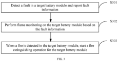
- FIG. 3 is a schematic flowchart of a battery safety monitoring method according to an embodiment of this application.
- the method includes the following steps.
- S301 Detect a fault in a target battery module and report fault information.
- Each battery pack may include one or more battery modules.
- Each battery module may further include one or more batteries.
- space used for concentrating batteries may be an energy storage container or the like.
- the battery in this embodiment may be a sodium-ion battery, a magnesium-ion battery, an aluminum battery, a potassium-ion battery, a lead-acid battery, a nickel cadmium battery, a nickel metal hydride battery, a lithium-ion battery, or the like.
- a battery type is not limited in this embodiment.
- the battery in this embodiment may also be replaced with another energy storage product.
- One or more fault detection sensors may be deployed around each battery module or each battery in the space, and whether the one or more battery modules are faulty may be detected by using the one or more fault detection sensors.
- the position information of the target battery module may be obtained by using the sensor deployed around the target battery module.
- the fault detection sensor configured to detect whether a fault occurs in the battery module and the sensor configured to obtain the position information of the target battery module may be a same sensor.
- the sensor has both a battery fault detection function and a position information obtaining function.
- the sensor configured to detect whether a fault in the battery module and the sensor configured to obtain the position information of the target battery module may be different sensors. That is, the fault detection sensor with a battery fault detection function detects whether a fault occurs in the battery module, and a sensor with a location information obtaining function obtains the location information of the target battery module.
- S302 Perform flame monitoring on the target battery module based on the fault information.
- the central controller may further monitor whether the target battery module may cause a fire. Specifically, the central controller may control, based on the position information of the target battery module, the flame detection apparatus to perform flame monitoring on the target battery module, so as to improve accuracy of flame monitoring.
- the flame detection apparatus When detecting a fire in the target battery module, the flame detection apparatus reports fire information to the central controller, and the central controller controls the fire extinguishing apparatus to start the fire extinguishing operation for the target battery module, which improves accuracy of the fire extinguishing operation.
- the fire extinguishing operation includes one or more of the following: spraying a fire extinguishing agent to extinguish a fire, spraying water to extinguish a fire, spraying water spray to extinguish a fire, spraying fine water mist to extinguish a fire, or the like, used for fire extinguishing and cooling.
- the flame detection apparatus is controlled to perform flame monitoring on the target battery module when a fault is detected in the target battery module, to implement low-cost and accurate battery safety monitoring.
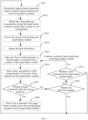
- FIG. 4 is a schematic flowchart of another battery safety monitoring method according to an embodiment of this application.
- the method includes the following steps.
- S401 Periodically adjust a flame monitoring angle to perform flame monitoring on one or more battery modules.
- a central controller may control a flame detection apparatus to periodically adjust the monitoring angle to perform flame monitoring on the one or more battery modules in a space.
- one energy storage module 4 (for example, a battery module) is stored in the space 1 (for example, an energy storage container) used for concentrating battery modules.
- the space 1 may further store more energy storage modules 4.
- the energy storage module 4 includes one or more batteries, and each battery has one cell 5.
- a fault detection sensor 2 is deployed on each energy storage module 4. All energy storage modules 4 may be subject to unified management and maintenance of a BMS 3.
- a central controller 8 is deployed in the space 1, and the central controller 8 may be a CPU, an MCU, or the like.
- the central controller 8 is configured to perform security monitoring on one or more energy storage modules 4 stored in the space 1.
- the central controller 8 is connected to the fault detection sensor 2.
- a flame detection apparatus may be further deployed in the space 1.
- the flame detection apparatus is connected to the central controller 8.
- the flame detection apparatus includes a flame detection sensor 6, a drive motor (not shown in the figure), and a posture adjustment base 7.
- the flame detection sensor 6 is disposed on the posture adjustment base 7.
- the flame detection sensor may be an infrared flame sensor, an ultraviolet flame sensor, a hybrid infrared and ultraviolet flame sensor, or the like.
- the drive motor may drive to adjust a monitoring angle of flame detection sensor 6.
- the monitoring angle of the flame detection sensor 6 may be 30 degrees to 180 degrees, and the flame detection sensor 6 is generally disposed at a middle top position or another open position at the top in the space 1.
- a fire extinguishing apparatus 9 is further deployed in the space 1 and is configured to perform a fire extinguishing operation.
- the fire extinguishing apparatus 9 is connected to the central controller 8 and the flame detection apparatus, and may also be connected to the fault detection sensor 2.
- the monitoring angle of the flame detection sensor 6 may be periodically adjusted by using the drive motor, to perform flame monitoring on the one or more energy storage modules 4 in the space 1.
- the flame detection sensor 6 is disposed to a preventive maintenance inspection state.
- the flame detection sensor 6 performs flame monitoring on the one or more energy storage modules 4 in the space 1 in sequence.
- Each time of monitoring may be performed at fixed time. For example, there are 10 energy storage modules 4 in the space 1.
- the one or more energy storage modules 4 in the space 1 are monitored every 10 minutes. In other words, a monitoring period is 10 minutes. Then, each energy storage module 4 may be monitored for 1 minute.
- the fire extinguishing apparatus 9 When the flame detection sensor 6 is disposed to the preventive maintenance inspection state, the fire extinguishing apparatus 9 performs no operation, so that the normal use of the space 1 is not affected.
- S402 Detect one or more of the following faults occurring in a cell of a battery in the target battery module: a cell temperature higher than a set temperature, a cell temperature rising speed higher than a set speed, a cell voltage lower than a set voltage, or a difference between a voltage of a cell of a first battery in a plurality of batteries included in the target battery module and a voltage of a cell of any one of the batteries, other than the first battery, in the target battery module greater than a set threshold.
- the fault detection sensor detects a fault in the target battery module.
- the fault detection sensor may detect one or more of the following faults occurring in the cell in the target battery module: overtemperature of the cell (for example, a temperature of the cell higher than a set temperature), a rapid temperature rise of the cell (for example, a temperature rising speed of the cell higher than a set speed), a voltage drop (for example, a voltage of the cell is lower than a set voltage), or voltage outlier (for example, a difference between a voltage of a cell of a first battery in a plurality of batteries included in the target battery module and a voltage of a cell of any of the batteries, other than the first battery, in the target battery module is greater than a set threshold). In this case, it may be considered that a fault occurs in the target battery module.
- the fault detection sensor 2 in FIG. 2 may detect one or more of the foregoing faults.
- a temperature sensor may be configured to detect a fault, for example, overtemperature of the cell or a rapid temperature rise of the cell; and/or a voltage sensor may be configured to detect a fault, for example, a voltage drop or voltage outlier.
- the fault detection sensor 2 may report the fault to the BMS 3, and then the BMS 3 reports the fault to the central controller 8.
- S403 Power off a power loop including the target battery module.
- the power loop including the target battery module may be first powered off.
- Powering off the power loop including the target battery module in a timely manner can avoid a fire in the power loop, and prevent the target battery module from damaging a component in the power loop and causing a greater loss.
- the fault information may include detailed information about one or more detected faults, or may be only used to indicate that a fault occurs in the target battery module.
- one or more battery modules are stored in the space.
- position information of the target battery module may be further obtained, so that when there is a fire in the space for storing the battery, quick detection and response can be implemented, and fire information can be reported and a fire extinguishing operation can be performed as early as possible, to control a disaster-affected range as much as possible.
- a position sensor may be further disposed on the energy storage module 4, and may be configured to obtain the position information of a target energy storage module 4.
- the central controller 8 may indicate the position sensor to report the position information of the target energy storage module 4. Therefore, the fault information may further include the position information of the target battery module.
- S405 Adjust the flame monitoring angle, so that the angle is consistent with a position of the target battery module.
- the flame detection sensor 6 After a fault is detected in the target battery module, the flame detection sensor 6 is controlled to exit the preventive maintenance inspection state, and the drive motor is controlled to adjust the flame monitoring angle of the flame detection sensor 6, so that the angle is consistent with the position of the target battery module, that is, the flame detection sensor 6 is specially for monitoring of the target battery module.
- S406 Start a timer, and perform, within timing duration of the timer, flame detection on the target battery module.
- the flame monitoring is continuously performed on the target battery module, to monitor whether the target battery module will be on fire.
- step S407 Determine whether a flame is detected within the timing duration. If yes, step S408 is performed; otherwise, step S409 is performed.
- the flame detection sensor 6 continuously performs flame monitoring on the target battery module, and determines in real time whether a flame is detected.
- the central controller 8 controls the fire extinguishing apparatus 9 to start the fire extinguishing operation for the target battery module, and accuracy of the fire extinguishing operation is improved.
- the fire extinguishing operation includes one or more of the following: spraying a fire extinguishing agent to extinguish a fire, spraying water to extinguish a fire, spraying water spray to extinguish a fire, spraying fine water mist to extinguish a fire, or the like.
- the fire extinguishing apparatus 9 may also be deployed with a sensor, and the fire extinguishing operation is triggered by using the sensor, to control fire in time.
- step S409 When no fire is detected in the target battery module, determine whether the timer has stopped. If yes, step S401 is performed; otherwise, step S410 is performed.
- step S410 Determine whether a fault is detected in the target battery module again. If yes, step S405 is performed to continue to perform flame monitoring on the target battery module; otherwise, step S401 is performed.
- the central controller 8 determines, based on the fault information reported by the fault detection sensor 2 in real time by using the BMS 3, whether a fault warning is cleared, in other words, whether a fault is detected in the target battery module again. If the warning is cleared, the monitoring angle of the flame detection sensor 6 is adjusted, so that the flame detection sensor 6 enters the preventive maintenance inspection state, and continues to periodically perform flame monitoring. If the warning is not cleared, flame monitoring continues to be performed on the target battery module.
- the flame detection apparatus is controlled to perform flame monitoring on the target battery module when detecting the fault information, for example, the overtemperature, the rapid temperature rise, the voltage drop, or the voltage outlier of the cell in a battery in the target battery module, to implement low-cost and accurate battery safety monitoring.
- the fault information for example, the overtemperature, the rapid temperature rise, the voltage drop, or the voltage outlier of the cell in a battery in the target battery module.
- FIG. 5 is a schematic flowchart of still another battery safety monitoring method according to an embodiment of this application.
- the method includes the following steps.
- S501 Periodically adjust a flame monitoring angle to perform flame monitoring on one or more battery modules.
- step S401 for specific implementation of this step, refer to step S401 in the embodiment shown in FIG. 4 . Details are not described herein again.
- S502 Detect that a flammable gas concentration around the target battery module is greater than or equal to a set concentration.
- a valve of a cell of one or more batteries in the target battery module may be opened, and a small amount of flammable gas is generated.
- the flammable gas includes hydrogen, carbon monoxide, volatile organic compound, or the like.
- a fault detection sensor may be a flammable gas sensor.
- the flammable gas concentration around the target battery module may be detected by using one or more flammable gas sensors of hydrogen, carbon monoxide, volatile organic compound, or the like.
- the flammable gas sensor may be deployed on each battery module or each battery in the battery module.
- the central controller 8 in FIG. 2 may communicate with a BMS 5, the flammable gas detection sensor, and the fire extinguishing apparatus 9 by using a CAN, 485, FE, or optical fiber.
- the flammable gas sensor When the flammable gas sensor detects that the flammable gas concentration around the target battery module is greater than or equal to the set concentration, the flammable gas sensor may send fault information to the BMS 5, and the BMS 5 reports the fault information to the central controller 8.
- the set concentration may be set based on an empirical value, or may be obtained in another manner.
- S503 Power off a power loop including the target battery module.
- step S403 For specific implementation of this step, refer to step S403 in the embodiment shown in FIG. 4 . Details are not described herein again.
- step S404 for specific implementation of this step, refer to step S404 in the embodiment shown in FIG. 4 . Details are not described herein again.
- step S405 in the embodiment shown in FIG. 4 . Details are not described herein again.
- S506 Start a timer and perform, within timing duration of the timer, flame detection on the target battery module.
- step S406 for specific implementation of this step, refer to step S406 in the embodiment shown in FIG. 4 . Details are not described herein again.
- step S507 Determine whether a flame is detected within the timing duration. If yes, step S508 is performed; otherwise, step S509 is performed.
- step S407 in the embodiment shown in FIG. 4 . Details are not described herein again.
- step S408 in the embodiment shown in FIG. 4 . Details are not described herein again.
- step S509 When no fire is detected in the target battery module, determine whether the timer has stopped. If yes, step S501 is performed; otherwise, step S510 is performed.
- step S409 in the embodiment shown in FIG. 4 . Details are not described herein again.
- step S510 Determine whether a fault is detected in the target battery module again. If yes, step S505 is performed to continue to perform flame monitoring on the target battery module; otherwise, step S501 is performed.
- step S410 for specific implementation of this step, refer to step S410 in the embodiment shown in FIG. 4 . Details are not described herein again.
- the flame detection apparatus is controlled to perform flame monitoring on the target battery module when detecting that the flammable gas concentration around the target battery module is greater than or equal to the set concentration, to implement low-cost and accurate battery safety monitoring.
- the quick detection and response can be implemented, and the fire information can be reported and the fire extinguishing operation can be performed as early as possible, to control a disaster-affected range as much as possible.
- An embodiment of this application further provides an energy storage system, including one or more power terminals, one or more battery modules, and the foregoing battery safety monitoring system.
- the one or more battery modules and the one or more power terminals form a power loop, and the battery safety monitoring system is configured to perform safety monitoring on the one or more battery modules.
- A/B may indicate A or B.
- a and B may be singular or plural.
- a plurality of means two or more than two unless otherwise specified.
- At least one of the following items (pieces)” or a similar expression thereof means any combination of these items, including any combination of singular items (pieces) or plural items (pieces).
- at least one of a, b, or c may indicate: a, b, c, a and b, a and c, b and c, or a, b, and c, where a, b, and c may be singular or plural.
- inventions may be implemented by software, hardware, firmware, or any combination thereof.
- a software program is used to implement embodiments, embodiments may be implemented completely or partially in a form of a computer program product.
- the computer program product includes one or more computer instructions.
- the computer program instructions When the computer program instructions are loaded and executed on a computer, the procedures or functions according to embodiments of this application are all or partially generated.
- the computer may be a general-purpose computer, a dedicated computer, a computer network, or another programmable apparatus.
- the computer instructions may be stored in a computer-readable storage medium or may be transmitted from a computer-readable storage medium to another computer-readable storage medium.
- the computer instructions may be transmitted from a website, computer, server, or data center to another website, computer, server, or data center in a wired (for example, a coaxial cable, an optical fiber, or a digital subscriber line (DSL)) or wireless (for example, infrared, radio, or microwave) manner.
- the computer-readable storage medium may be any usable medium accessible by the computer, or a data storage device, such as a server or a data center, integrating one or more usable media.
- the usable medium may be a magnetic medium (for example, a floppy disk, a hard disk, or a magnetic tape), an optical medium (for example, a DVD), a semiconductor medium (for example, SSD), or the like.
Landscapes
- Emergency Management (AREA)
- Business, Economics & Management (AREA)
- Chemical & Material Sciences (AREA)
- Engineering & Computer Science (AREA)
- Health & Medical Sciences (AREA)
- Public Health (AREA)
- Electrochemistry (AREA)
- General Chemical & Material Sciences (AREA)
- Chemical Kinetics & Catalysis (AREA)
- Manufacturing & Machinery (AREA)
- Physics & Mathematics (AREA)
- General Physics & Mathematics (AREA)
- Analytical Chemistry (AREA)
- Microelectronics & Electronic Packaging (AREA)
- Fire Alarms (AREA)
- Secondary Cells (AREA)
Abstract
Description
- This application relates to the field of energy storage technologies, and in particular, to a battery safety monitoring system and method, and an energy storage system.
- A lithium-ion battery is a secondary battery with high energy density, and is widely used for energy storage in the energy storage industry. However, due to its high discharge power and flammable electrolyte, there are many safety risks, including battery thermal abuse and thermal runaway. Therefore, open fire detection needs to be performed on an energy storage battery container in real time. Currently, an existing method is to detect open fire by configuring an infrared/ultraviolet flame sensor, or detect open fire with solutions of video surveillance and deep learning. However, both solutions have specific defects. For the former, because the energy storage container has a narrow space and there are many obstacles, a plurality of sensors need to be configured for detection. In addition, electric arcs or the like may cause false alarms. This method is generally applicable to open fire detection in open areas. Because the cost of the energy storage container is high, and sensors are densely deployed in the energy storage container, it is difficult to maintain the container when the sensors are faulty. For the latter, fire in the energy storage container is usually caused by battery thermal runaway. As a result, smoke goes high before there is open fire, and the risk of failing to report is high.
- It can be learned that the existing open fire detection solutions are mainly applicable to fire extinguishing in spacious areas and buildings, but cannot adapt to a special environment of the energy storage container and a specific feature of battery fire, and there are problems such as high costs and high possibility of missed detection. Therefore, a low-cost and accurate solution for battery safety monitoring is urgently needed.
- This application provides a battery safety monitoring system and method, and an energy storage system, to monitor battery safety accurately and at a low cost.
- According to a first aspect, a battery safety monitoring system is provided. The battery safety monitoring system is used for safety monitoring of one or more battery modules. The battery safety monitoring system includes a central controller, a fault detection sensor, a flame detection apparatus, and a fire extinguishing apparatus. The fault detection sensor is configured to detect a fault in a target battery module and send fault information to the central controller. The central controller is configured to control the flame detection apparatus to perform flame detection on the target battery module based on the fault information. The flame detection apparatus is configured to send, when detecting a fire in the target battery module, fire information to the central controller. The central controller is further configured to control the fire extinguishing apparatus to start a fire extinguishing operation for the target battery module.
- In this aspect, there is no need to deploy excessive sensors. Instead, the flame detection apparatus is controlled to perform flame monitoring on the target battery module when a fault is detected in the target battery module, to implement low-cost and accurate battery safety monitoring.
- In a possible implementation, the fault detection sensor is configured to detect one or more of the following faults occurring in a cell of a battery in the target battery module: a cell temperature higher than a set temperature, a cell temperature rising speed higher than a set speed, a cell voltage lower than a set voltage, or a difference between a voltage of a cell of a first battery in a plurality of batteries included in the target battery module and a voltage of a cell of any one of the batteries, other than the first battery, in the target battery module greater than a set threshold.
- In this implementation, whether a fault occurs in the battery module may be detected by detecting fault information such as overtemperature, an excessive temperature rise of the cell, a voltage drop, voltage outlier, or the like. The foregoing fault information may be detected or collected by a battery management system (BMS).
- In another possible implementation, the fault detection sensor is configured to detect that a flammable gas concentration around the target battery module is greater than or equal to a set concentration.
- In this implementation, when one or more batteries in the target battery module are faulty, a valve of a cell of one or more batteries in the target battery module may be opened, and a small amount of flammable gas is generated. When the flammable gas reaches a certain concentration, a fire may occur. Therefore, whether a fault is detected in the target battery module may be determined by detecting whether the flammable gas concentration of the target battery module is greater than or equal to the set concentration.
- In still another possible implementation, the flame detection apparatus includes a flame detection sensor, a drive motor, and a posture adjustment base. The flame detection sensor is located on the posture adjustment base, and the drive motor is connected to the flame detection sensor and the posture adjustment base. The central controller is further configured to send position information of the target battery module to the drive motor. The drive motor is configured to drive to adjust a flame monitoring angle of the posture adjustment base, so that the angle is consistent with a position of the target battery module. The flame detection sensor is configured to continuously perform flame monitoring on the target battery module.
- In this implementation, the flame monitoring angle of the posture adjustment base of the flame detection apparatus is adjusted, so that the angle is consistent with the position of the target battery module, so that flame monitoring can be accurately performed on the target battery module. In addition, there is no need to deploy excessive flame detection sensors to perform flame monitoring, which reduces monitoring costs.
- In still another possible implementation, the drive motor is further configured to periodically drive to adjust the flame monitoring angle of the posture adjustment base; and the flame detection sensor is further configured to perform flame monitoring on the one or more battery modules.
- In this implementation, when no fault is detected in any battery module, fire preventive maintenance inspection may be performed on one or more battery modules in a space, so as to discover a fire in a timely manner.
- In still another possible implementation, the central controller is further configured to start a timer after receiving the fault information of the target battery module. The central controller is further configured to control, within timing duration of the timer, the flame detection apparatus to perform flame detection on the target battery module. The central controller is further configured to: receive, within the timing duration of the timer, the fire information sent by the flame detection apparatus, and control the fire extinguishing apparatus to start the fire extinguishing operation for the target battery module.
- In this implementation, the timer is set to continuously monitor, within specific duration, whether a fire occurs in the faulty target battery module, so that safety of the target battery module can be accurately and reliably monitored.
- In still another possible implementation, the central controller is further configured to: if the fire information sent by the flame detection apparatus is not received within the timing duration of the timer, and the central controller receives the fault information of the target battery module again, control the flame detection apparatus to continue to perform flame monitoring on the target battery module.
- In this implementation, the timer is set to continuously monitor, within specific duration, whether a fire occurs in the faulty target battery module, so that safety of the target battery module can be accurately and reliably monitored.
- In still another possible implementation, the central controller is further configured to power off a power loop including the target battery module.
- In this implementation, after a fault is detected in the target battery module, the power loop including the target battery module is powered off in a timely manner, to avoid a fire in the power loop, and prevent a component from being burned down, which causes a greater loss.
- According to a second aspect, a battery safety monitoring method is provided. The method includes: detecting a fault in a target battery module and reporting fault information; performing flame monitoring on the target battery module based on the fault information; and detecting a fire in the target battery module, starting a fire extinguishing operation for the target battery module.
- In a possible implementation, the detecting a fault in a target battery module includes detecting one or more of the following faults occurring in a cell of a battery in the target battery module: a cell temperature higher than a set temperature, a cell temperature rising speed higher than a set speed, a cell voltage lower than a set voltage, or a difference between a voltage of a cell of a first battery in a plurality of batteries included in the target battery module and a voltage of a cell of any one of the batteries, other than the first battery, in the target battery module greater than a set threshold.
- In another possible implementation, the detecting a fault in a target battery module includes detecting that a flammable gas concentration around the target battery module is greater than or equal to a set concentration.
- In still another possible implementation, the performing flame monitoring on the target battery module includes: adjusting a flame monitoring angle, so that the angle is consistent with a position of the target battery module; and continuously performing flame monitoring on the target battery module.
- In still another possible implementation, before the detecting a fault in a target battery module, the method further includes: periodically adjusting the flame monitoring angle; and performing flame monitoring on the one or more battery modules.
- In still another possible implementation, the continuously performing flame monitoring on the target battery module includes: when a fault is detected in the target battery module, starting a timer; and performing, within timing duration of the timer, flame detection on the target battery module. The starting a fire extinguishing operation for the target battery module includes: when a fire is detected in the target battery module within the timing duration of the timer, starting a fire extinguishing operation for the target battery module.
- In still another possible implementation, the method further includes: continuing to perform flame monitoring on the target battery module if it is not detected, within the timing duration of the timer, that a fire occurs in the target battery module, and it is detected again that a fault occurs in the target battery module.
- In still another possible implementation, after the detecting a fault in a target battery module, the method further includes: powering off a power loop including the target battery module.
- According to a third aspect, an energy storage system is provided, including one or more power terminals, one or more battery modules, and the battery safety monitoring system according to any one of the first aspect or the implementations of the first aspect. The one or more battery modules and the one or more power terminals form a power loop, and the battery safety monitoring system is configured to perform safety monitoring on the one or more battery modules.
-
-
FIG. 1 is a schematic diagram of a structure of a battery safety monitoring system according to an embodiment of this application; -
FIG. 2 is a schematic diagram of a structure of another example battery safety monitoring system according to an embodiment of this application; -
FIG. 3 is a schematic flowchart of a battery safety monitoring method according to an embodiment of this application; -
FIG. 4 is a flowchart of another battery safety monitoring method according to an embodiment of this application; and -
FIG. 5 is a schematic flowchart of still another battery safety monitoring method according to an embodiment of this application. - The following describes embodiments of this application with reference to accompanying drawings in embodiments of this application.
- Existing open fire detection solutions proposed in the background are mainly applicable to fire extinguishing in wide areas and buildings. They cannot adapt to a special environment of the energy storage container and a unique nature of battery fire, and has problems such as high costs and high possibility of missed detection. This application provides a battery safety monitoring solution. There is no need to deploy excessive sensors. Instead, a flame detection apparatus is controlled to perform flame monitoring on a target battery module when a fault is detected in the target battery module, to implement low-cost and accurate battery safety monitoring, and control a disaster-affected range as much as possible.
-
FIG. 1 is a schematic diagram of a structure of a battery safety monitoring system according to an embodiment of this application. A batterysafety monitoring system 1000 is configured to perform safety monitoring on one or more battery modules. The batterysafety monitoring system 1000 includes acentral controller 101, afault detection sensor 102, aflame detection apparatus 103, and afire extinguishing apparatus 104. - The
fault detection sensor 102 is configured to detect a fault in a target battery module, and send fault information to the central controller. - The
central controller 101 is configured to control, based on the fault information, theflame detection apparatus 103 to perform flame detection on the target battery module. - The
flame detection apparatus 103 is configured to send, when detecting a fire in the target battery module, fire information to thecentral controller 101. - The
central controller 101 is further configured to control thefire extinguishing apparatus 104 to start a fire extinguishing operation for the target battery module. - In a possible implementation, the
fault detection sensor 102 is configured to detect one or more of the following faults occurring in a cell of a battery in the target battery module: a cell temperature higher than a set temperature, a cell temperature rising speed higher than a set speed, a cell voltage lower than a set voltage, or a difference between a voltage of a cell of a first battery in a plurality of batteries included in the target battery module and a voltage of a cell of any one of the batteries, other than the first battery, in the target battery module greater than a set threshold. - In another possible implementation, the
fault detection sensor 102 is configured to detect that a flammable gas concentration around the target battery module is greater than or equal to a set concentration. - In still another implementation, the
flame detection apparatus 103 includes a flame detection sensor, a drive motor, and a posture adjustment base (which are not shown in the figure). The flame detection sensor is located on the posture adjustment base, and the drive motor is connected to the flame detection sensor and the posture adjustment base. - The
central controller 101 is further configured to send position information of the target battery module to the drive motor. - The drive motor is configured to drive to adjust a flame monitoring angle of the posture adjustment base, so that the angle is consistent with a position of the target battery module.
- The flame detection sensor is configured to continuously perform flame monitoring on the target battery module.
- In still another implementation, the drive motor is further configured to periodically drive to adjust the flame monitoring angle of the posture adjustment base.
- The flame detection sensor is further configured to perform flame monitoring on the one or more battery modules.
- In still another possible implementation, the
central controller 101 is further configured to start a timer after receiving the fault information of the target battery module. - The
central controller 101 is further configured to control, within timing duration of the timer, theflame detection apparatus 103 to perform flame detection on the target battery module. - The
central controller 101 is further configured to: receive, within the timing duration of the timer, the fire information sent by theflame detection apparatus 103, and control thefire extinguishing apparatus 104 to start the fire extinguishing operation for the target battery module. - In still another possible implementation, the
central controller 101 is further configured to: if the fire information sent by theflame detection apparatus 103 is not received within the timing duration of the timer, and thecentral controller 101 receives the fault information of the target battery module again, control theflame detection apparatus 103 to continue to perform flame monitoring on the target battery module. - In still another possible implementation, the
central controller 101 is further configured to power off a power loop including the target battery module. - For example, the foregoing central controller may be a central processing unit (CPU) or a micro control unit (MCU).
- The central controller may further include a hardware chip. The hardware chip may be an application-specific integrated circuit (ASIC), a programmable logic device (PLD), or a combination thereof. The PLD may be a complex programmable logic device (CPLD), a field programmable logic gate array (FPGA), a generic array logic (GAL), or any combination thereof.
- The battery safety monitoring system may further include a memory, configured to store the foregoing fault information, a program of the central controller, or the like. The memory may include a volatile memory, for example, a random access memory (RAM). The memory may alternatively include a non-volatile memory, for example, a flash memory, a hard disk drive (HDD), or a solid-state drive (SSD). The memory may alternatively include a combination of the foregoing types of memories.
- According to the battery safety monitoring system provided in this embodiment of this application, there is no need to deploy excessive sensors. Instead, the flame detection apparatus is controlled to perform flame monitoring on the target battery module when a fault is detected in the target battery module, to implement low-cost and accurate battery safety monitoring, and control a disaster-affected range as much as possible.
-
FIG. 2 is a schematic diagram a structure of another example battery safety monitoring system according to an embodiment of this application. For example, one energy storage module 4 (for example, a battery module) is stored in a space 1 (for example, an energy storage container) used for concentrating storing battery modules. Certainly, the space 1 may further store moreenergy storage modules 4. Theenergy storage module 4 includes one or more batteries, and each battery has onecell 5. Afault detection sensor 2 is deployed on eachenergy storage module 4. Allenergy storage modules 4 may be subject to unified management and maintenance of aBMS 3. - A
central controller 8 is deployed in the space 1, and thecentral controller 8 may be a CPU, an MCU, or the like. Thecentral controller 8 is configured to perform security monitoring on one or moreenergy storage modules 4 stored in the space 1. - The
central controller 8 is connected to thefault detection sensor 2. - A flame detection apparatus may be further deployed in the space 1. The flame detection apparatus is connected to the
central controller 8. The flame detection apparatus includes aflame detection sensor 6, a drive motor (not shown in the figure), and aposture adjustment base 7. Theflame detection sensor 6 is disposed on theposture adjustment base 7. The flame detection sensor may be an infrared flame sensor, an ultraviolet flame sensor, a hybrid infrared and ultraviolet flame sensor, or the like. The drive motor may drive to adjust a monitoring angle offlame detection sensor 6. For example, a monitoring angle of theflame detection sensor 6 may be 30 degrees to 180 degrees, and theflame detection sensor 6 is generally disposed at a middle top position or another open position at the top in the space 1. - A
fire extinguishing apparatus 9 is further deployed in the space 1 and is configured to perform a fire extinguishing operation. Thefire extinguishing apparatus 9 is connected to thecentral controller 8 and the flame detection apparatus, and may also be connected to thefault detection sensor 2. - For example, the
central controller 8 may communicate with theBMS 3, theflame detection sensor 6, and thefire extinguishing apparatus 9 by using a controller area network (CAN), 485, fast ethernet (FE), or an optical fiber. - Before a fault in a target battery module is detected in the space 1, the monitoring angle of the
flame detection sensor 6 may be periodically adjusted by using the drive motor, to perform flame monitoring on the one or moreenergy storage modules 4 in the space 1. In this case, theflame detection sensor 6 is disposed to a preventive maintenance inspection state. In one period, theflame detection sensor 6 performs flame monitoring on the one or moreenergy storage modules 4 in the space 1 in sequence. Each time of monitoring may be performed at fixed time. For example, there are 10energy storage modules 4 in the space 1. The one or moreenergy storage modules 4 in the space 1 are monitored every 10 minutes. In other words, a monitoring period is 10 minutes. Then, eachenergy storage module 4 may be monitored for 1 minute. - When the
flame detection sensor 6 is disposed to the preventive maintenance inspection state, thefire extinguishing apparatus 9 performs no operation, so that normal use of the space 1 is not affected. - When a fault is detected in the target battery module, the
central controller 8 controls theflame detection sensor 6 to exit the preventive maintenance inspection state, and controls the drive motor to adjust the monitoring angle of theflame detection sensor 6, so that the monitoring angle is consistent with a position of the target battery module, that is, theflame detection sensor 6 is specially for monitoring of the target battery module. - The
flame detection sensor 6 continuously performs flame monitoring on the target battery module, and determines in real time whether a flame is detected. - When a fire is detected in the target battery module, the
central controller 8 controls thefire extinguishing apparatus 9 to start the fire extinguishing operation for the target battery module, which improves accuracy of the fire extinguishing operation. For example, the fire extinguishing operation includes one or more of the following: spraying a fire extinguishing agent to extinguish a fire, spraying water to extinguish a fire, spraying water spray to extinguish a fire, spraying fine water mist to extinguish a fire, or the like. - Further, the
fire extinguishing apparatus 9 may also be deployed with a sensor, and the fire extinguishing operation is triggered by using the sensor, to control fire in time. - With reference to a procedure of a battery safety monitoring method, the following describes in detail how the battery safety monitoring system performs battery safety monitoring.
-
FIG. 3 is a schematic flowchart of a battery safety monitoring method according to an embodiment of this application. For example, the method includes the following steps. - S301: Detect a fault in a target battery module and report fault information.
- To save storage space or facilitate centralized management and maintenance, one or more battery packs may be stored in one space. Each battery pack may include one or more battery modules. Each battery module may further include one or more batteries. For example, space used for concentrating batteries may be an energy storage container or the like.
- The battery in this embodiment may be a sodium-ion battery, a magnesium-ion battery, an aluminum battery, a potassium-ion battery, a lead-acid battery, a nickel cadmium battery, a nickel metal hydride battery, a lithium-ion battery, or the like. A battery type is not limited in this embodiment. The battery in this embodiment may also be replaced with another energy storage product.
- Because of high discharge power and flammable electrolyte of the battery, there are many safety risks, including battery thermal abuse and thermal runaway. Because batteries are stored in a centralized manner, security monitoring of battery modules is very important and difficult.
- One or more fault detection sensors may be deployed around each battery module or each battery in the space, and whether the one or more battery modules are faulty may be detected by using the one or more fault detection sensors.
- Further, because one or more battery modules are stored in the foregoing space, to accurately perform further flame monitoring on the target battery module, when a fault is detected in the target battery module, position information of the target battery module may be further obtained.
- The position information of the target battery module may be obtained by using the sensor deployed around the target battery module.
- For example, the fault detection sensor configured to detect whether a fault occurs in the battery module and the sensor configured to obtain the position information of the target battery module may be a same sensor. In other words, the sensor has both a battery fault detection function and a position information obtaining function. Alternatively, the sensor configured to detect whether a fault in the battery module and the sensor configured to obtain the position information of the target battery module may be different sensors. That is, the fault detection sensor with a battery fault detection function detects whether a fault occurs in the battery module, and a sensor with a location information obtaining function obtains the location information of the target battery module.
- S302: Perform flame monitoring on the target battery module based on the fault information.
- After a fault is detected in the target battery module, the central controller may further monitor whether the target battery module may cause a fire. Specifically, the central controller may control, based on the position information of the target battery module, the flame detection apparatus to perform flame monitoring on the target battery module, so as to improve accuracy of flame monitoring.
- S303: When a fire is detected in the target battery module, start a fire extinguishing operation for the target battery module.
- When detecting a fire in the target battery module, the flame detection apparatus reports fire information to the central controller, and the central controller controls the fire extinguishing apparatus to start the fire extinguishing operation for the target battery module, which improves accuracy of the fire extinguishing operation.
- For example, the fire extinguishing operation includes one or more of the following: spraying a fire extinguishing agent to extinguish a fire, spraying water to extinguish a fire, spraying water spray to extinguish a fire, spraying fine water mist to extinguish a fire, or the like, used for fire extinguishing and cooling.
- According to the battery safety monitoring method provided in this embodiment of this application, there is no need to deploy excessive sensors. Instead, the flame detection apparatus is controlled to perform flame monitoring on the target battery module when a fault is detected in the target battery module, to implement low-cost and accurate battery safety monitoring.
-
FIG. 4 is a schematic flowchart of another battery safety monitoring method according to an embodiment of this application. For example, the method includes the following steps. - S401: Periodically adjust a flame monitoring angle to perform flame monitoring on one or more battery modules.
- When a fault detection sensor detects no fault in a target battery module, a central controller may control a flame detection apparatus to periodically adjust the monitoring angle to perform flame monitoring on the one or more battery modules in a space.
- According to the battery safety monitoring system shown in
FIG. 2 , for example, one energy storage module 4 (for example, a battery module) is stored in the space 1 (for example, an energy storage container) used for concentrating battery modules. Certainly, the space 1 may further store moreenergy storage modules 4. Theenergy storage module 4 includes one or more batteries, and each battery has onecell 5. Afault detection sensor 2 is deployed on eachenergy storage module 4. Allenergy storage modules 4 may be subject to unified management and maintenance of aBMS 3. - A
central controller 8 is deployed in the space 1, and thecentral controller 8 may be a CPU, an MCU, or the like. Thecentral controller 8 is configured to perform security monitoring on one or moreenergy storage modules 4 stored in the space 1. - The
central controller 8 is connected to thefault detection sensor 2. - A flame detection apparatus may be further deployed in the space 1. The flame detection apparatus is connected to the
central controller 8. The flame detection apparatus includes aflame detection sensor 6, a drive motor (not shown in the figure), and aposture adjustment base 7. Theflame detection sensor 6 is disposed on theposture adjustment base 7. The flame detection sensor may be an infrared flame sensor, an ultraviolet flame sensor, a hybrid infrared and ultraviolet flame sensor, or the like. The drive motor may drive to adjust a monitoring angle offlame detection sensor 6. For example, the monitoring angle of theflame detection sensor 6 may be 30 degrees to 180 degrees, and theflame detection sensor 6 is generally disposed at a middle top position or another open position at the top in the space 1. - A
fire extinguishing apparatus 9 is further deployed in the space 1 and is configured to perform a fire extinguishing operation. Thefire extinguishing apparatus 9 is connected to thecentral controller 8 and the flame detection apparatus, and may also be connected to thefault detection sensor 2. - Before a fault is detected in the target battery module in the space 1, the monitoring angle of the
flame detection sensor 6 may be periodically adjusted by using the drive motor, to perform flame monitoring on the one or moreenergy storage modules 4 in the space 1. In this case, theflame detection sensor 6 is disposed to a preventive maintenance inspection state. In one period, theflame detection sensor 6 performs flame monitoring on the one or moreenergy storage modules 4 in the space 1 in sequence. Each time of monitoring may be performed at fixed time. For example, there are 10energy storage modules 4 in the space 1. The one or moreenergy storage modules 4 in the space 1 are monitored every 10 minutes. In other words, a monitoring period is 10 minutes. Then, eachenergy storage module 4 may be monitored for 1 minute. - When the
flame detection sensor 6 is disposed to the preventive maintenance inspection state, thefire extinguishing apparatus 9 performs no operation, so that the normal use of the space 1 is not affected. - S402: Detect one or more of the following faults occurring in a cell of a battery in the target battery module: a cell temperature higher than a set temperature, a cell temperature rising speed higher than a set speed, a cell voltage lower than a set voltage, or a difference between a voltage of a cell of a first battery in a plurality of batteries included in the target battery module and a voltage of a cell of any one of the batteries, other than the first battery, in the target battery module greater than a set threshold.
- The fault detection sensor detects a fault in the target battery module. Specifically, the fault detection sensor may detect one or more of the following faults occurring in the cell in the target battery module: overtemperature of the cell (for example, a temperature of the cell higher than a set temperature), a rapid temperature rise of the cell (for example, a temperature rising speed of the cell higher than a set speed), a voltage drop (for example, a voltage of the cell is lower than a set voltage), or voltage outlier (for example, a difference between a voltage of a cell of a first battery in a plurality of batteries included in the target battery module and a voltage of a cell of any of the batteries, other than the first battery, in the target battery module is greater than a set threshold). In this case, it may be considered that a fault occurs in the target battery module.
- The
fault detection sensor 2 inFIG. 2 may detect one or more of the foregoing faults. Specifically, a temperature sensor may be configured to detect a fault, for example, overtemperature of the cell or a rapid temperature rise of the cell; and/or a voltage sensor may be configured to detect a fault, for example, a voltage drop or voltage outlier. - As shown in
FIG. 2 , after detecting one or more of the foregoing faults, thefault detection sensor 2 may report the fault to theBMS 3, and then theBMS 3 reports the fault to thecentral controller 8. - S403: Power off a power loop including the target battery module.
- After one or more of the foregoing faults occurring in the cell in the target battery module are detected, the power loop including the target battery module may be first powered off.
- Powering off the power loop including the target battery module in a timely manner can avoid a fire in the power loop, and prevent the target battery module from damaging a component in the power loop and causing a greater loss.
- S404: Report fault information.
- The fault information may include detailed information about one or more detected faults, or may be only used to indicate that a fault occurs in the target battery module.
- Generally, one or more battery modules are stored in the space. To further accurately perform flame monitoring on the target battery module, when a fault in the target battery module is detected, position information of the target battery module may be further obtained, so that when there is a fire in the space for storing the battery, quick detection and response can be implemented, and fire information can be reported and a fire extinguishing operation can be performed as early as possible, to control a disaster-affected range as much as possible. As shown in
FIG. 2 , a position sensor may be further disposed on theenergy storage module 4, and may be configured to obtain the position information of a targetenergy storage module 4. After receiving the information that is reported by theBMS 3 and that indicates that a fault occurs in theenergy storage module 4, thecentral controller 8 may indicate the position sensor to report the position information of the targetenergy storage module 4. Therefore, the fault information may further include the position information of the target battery module. - S405: Adjust the flame monitoring angle, so that the angle is consistent with a position of the target battery module.
- After a fault is detected in the target battery module, the
flame detection sensor 6 is controlled to exit the preventive maintenance inspection state, and the drive motor is controlled to adjust the flame monitoring angle of theflame detection sensor 6, so that the angle is consistent with the position of the target battery module, that is, theflame detection sensor 6 is specially for monitoring of the target battery module. - S406: Start a timer, and perform, within timing duration of the timer, flame detection on the target battery module.
- When a fault is detected in the target battery module, the flame monitoring is continuously performed on the target battery module, to monitor whether the target battery module will be on fire.
- S407: Determine whether a flame is detected within the timing duration. If yes, step S408 is performed; otherwise, step S409 is performed.
- The
flame detection sensor 6 continuously performs flame monitoring on the target battery module, and determines in real time whether a flame is detected. - S408: When a fire is detected in the target battery module, start the fire extinguishing operation for the target battery module.
- When a fire in the target battery module is detected, the
central controller 8 controls thefire extinguishing apparatus 9 to start the fire extinguishing operation for the target battery module, and accuracy of the fire extinguishing operation is improved. For example, the fire extinguishing operation includes one or more of the following: spraying a fire extinguishing agent to extinguish a fire, spraying water to extinguish a fire, spraying water spray to extinguish a fire, spraying fine water mist to extinguish a fire, or the like. - Further, the
fire extinguishing apparatus 9 may also be deployed with a sensor, and the fire extinguishing operation is triggered by using the sensor, to control fire in time. - S409: When no fire is detected in the target battery module, determine whether the timer has stopped. If yes, step S401 is performed; otherwise, step S410 is performed.
- If no fire is detected in the target battery module, and the timer is still counting, the monitoring continues.
- S410: Determine whether a fault is detected in the target battery module again. If yes, step S405 is performed to continue to perform flame monitoring on the target battery module; otherwise, step S401 is performed.
- If no fire is detected in the target battery module within the timing duration of the timer, the
central controller 8 determines, based on the fault information reported by thefault detection sensor 2 in real time by using theBMS 3, whether a fault warning is cleared, in other words, whether a fault is detected in the target battery module again. If the warning is cleared, the monitoring angle of theflame detection sensor 6 is adjusted, so that theflame detection sensor 6 enters the preventive maintenance inspection state, and continues to periodically perform flame monitoring. If the warning is not cleared, flame monitoring continues to be performed on the target battery module. - According to the battery safety monitoring method provided in this embodiment of this application, there is no need to deploy excessive sensors. Instead, the flame detection apparatus is controlled to perform flame monitoring on the target battery module when detecting the fault information, for example, the overtemperature, the rapid temperature rise, the voltage drop, or the voltage outlier of the cell in a battery in the target battery module, to implement low-cost and accurate battery safety monitoring. In this way, quick detection and response can be implemented, and the fire information can be reported and the fire extinguishing operation can be performed as early as possible, to control a disaster-affected range as much as possible.
-
FIG. 5 is a schematic flowchart of still another battery safety monitoring method according to an embodiment of this application. For example, the method includes the following steps. - S501: Periodically adjust a flame monitoring angle to perform flame monitoring on one or more battery modules.
- For specific implementation of this step, refer to step S401 in the embodiment shown in
FIG. 4 . Details are not described herein again. - S502: Detect that a flammable gas concentration around the target battery module is greater than or equal to a set concentration.
- When a fault is detected in the target battery module, a valve of a cell of one or more batteries in the target battery module may be opened, and a small amount of flammable gas is generated. The flammable gas includes hydrogen, carbon monoxide, volatile organic compound, or the like.
- When duration in which the valve of the cell of the one or more batteries in the target battery module is open is long, or a quantity of cells in the target battery module whose valves are open is large, the flammable gas concentration may be increasingly large. In this embodiment, a fault detection sensor may be a flammable gas sensor. To be specific, the flammable gas concentration around the target battery module may be detected by using one or more flammable gas sensors of hydrogen, carbon monoxide, volatile organic compound, or the like.
- The flammable gas sensor may be deployed on each battery module or each battery in the battery module. The
central controller 8 inFIG. 2 may communicate with aBMS 5, the flammable gas detection sensor, and thefire extinguishing apparatus 9 by using a CAN, 485, FE, or optical fiber. - When the flammable gas sensor detects that the flammable gas concentration around the target battery module is greater than or equal to the set concentration, the flammable gas sensor may send fault information to the
BMS 5, and theBMS 5 reports the fault information to thecentral controller 8. The set concentration may be set based on an empirical value, or may be obtained in another manner. - S503: Power off a power loop including the target battery module.
- For specific implementation of this step, refer to step S403 in the embodiment shown in
FIG. 4 . Details are not described herein again. - S504: Report the fault information.
- For specific implementation of this step, refer to step S404 in the embodiment shown in
FIG. 4 . Details are not described herein again. - S505: Adjust the flame monitoring angle, so that the angle is consistent with a position of the target battery module.
- For specific implementation of this step, refer to step S405 in the embodiment shown in
FIG. 4 . Details are not described herein again. - S506: Start a timer and perform, within timing duration of the timer, flame detection on the target battery module.
- For specific implementation of this step, refer to step S406 in the embodiment shown in
FIG. 4 . Details are not described herein again. - S507: Determine whether a flame is detected within the timing duration. If yes, step S508 is performed; otherwise, step S509 is performed.
- For specific implementation of this step, refer to step S407 in the embodiment shown in
FIG. 4 . Details are not described herein again. - S508: When a fire is detected in the target battery module, start a fire extinguishing operation for the target battery module.
- For specific implementation of this step, refer to step S408 in the embodiment shown in
FIG. 4 . Details are not described herein again. - S509: When no fire is detected in the target battery module, determine whether the timer has stopped. If yes, step S501 is performed; otherwise, step S510 is performed.
- For specific implementation of this step, refer to step S409 in the embodiment shown in
FIG. 4 . Details are not described herein again. - S510: Determine whether a fault is detected in the target battery module again. If yes, step S505 is performed to continue to perform flame monitoring on the target battery module; otherwise, step S501 is performed.
- For specific implementation of this step, refer to step S410 in the embodiment shown in
FIG. 4 . Details are not described herein again. - According to the battery safety monitoring method provided in this embodiment of this application, there is no need to deploy excessive sensors. Instead, the flame detection apparatus is controlled to perform flame monitoring on the target battery module when detecting that the flammable gas concentration around the target battery module is greater than or equal to the set concentration, to implement low-cost and accurate battery safety monitoring. In this way, the quick detection and response can be implemented, and the fire information can be reported and the fire extinguishing operation can be performed as early as possible, to control a disaster-affected range as much as possible.
- An embodiment of this application further provides an energy storage system, including one or more power terminals, one or more battery modules, and the foregoing battery safety monitoring system. The one or more battery modules and the one or more power terminals form a power loop, and the battery safety monitoring system is configured to perform safety monitoring on the one or more battery modules.
- It should be understood that unless otherwise specified, "/" in descriptions of this application indicates an "or" relationship between associated objects. For example, A/B may indicate A or B. A and B may be singular or plural. In addition, in descriptions of this application, "a plurality of" means two or more than two unless otherwise specified. "At least one of the following items (pieces)" or a similar expression thereof means any combination of these items, including any combination of singular items (pieces) or plural items (pieces). For example, at least one of a, b, or c may indicate: a, b, c, a and b, a and c, b and c, or a, b, and c, where a, b, and c may be singular or plural. In addition, to clearly describe the technical solutions in embodiments of this application, terms such as "first" and "second" are used in embodiments of this application to distinguish between same items or similar items that provide basically same functions or purposes. A person skilled in the art may understand that the terms such as "first" and "second" do not limit a quantity and an execution sequence, and the terms such as "first" and "second" do not indicate a definite difference. In addition, in embodiments of this application, the word such as "example" or "for example" is used to represent giving an example, an illustration, or a description. Any embodiment or design scheme described as an "example" or "for example" in embodiments of this application should not be explained as being more preferred or having more advantages than another embodiment or design scheme. Exactly, use of the word such as "example" or "for example" is intended to present a relative concept in a specific manner for ease of understanding.
- All or some of the foregoing embodiments may be implemented by software, hardware, firmware, or any combination thereof. When a software program is used to implement embodiments, embodiments may be implemented completely or partially in a form of a computer program product. The computer program product includes one or more computer instructions. When the computer program instructions are loaded and executed on a computer, the procedures or functions according to embodiments of this application are all or partially generated. The computer may be a general-purpose computer, a dedicated computer, a computer network, or another programmable apparatus. The computer instructions may be stored in a computer-readable storage medium or may be transmitted from a computer-readable storage medium to another computer-readable storage medium. For example, the computer instructions may be transmitted from a website, computer, server, or data center to another website, computer, server, or data center in a wired (for example, a coaxial cable, an optical fiber, or a digital subscriber line (DSL)) or wireless (for example, infrared, radio, or microwave) manner. The computer-readable storage medium may be any usable medium accessible by the computer, or a data storage device, such as a server or a data center, integrating one or more usable media. The usable medium may be a magnetic medium (for example, a floppy disk, a hard disk, or a magnetic tape), an optical medium (for example, a DVD), a semiconductor medium (for example, SSD), or the like.
- Although this application is described with reference to embodiments, in a process of implementing this application that claims protection, a person skilled in the art may understand and implement another variation of the disclosed embodiments by viewing the accompanying drawings, disclosed content, and appended claims. In the claims, "comprising" (comprising) does not exclude another component or another step, and "a" or "one" does not exclude a case of multiple. A single processor or another unit may implement several functions enumerated in the claims. Some measures are disclosed in dependent claims that are different from each other, but this does not mean that these measures cannot be combined to produce a good effect.
Claims (15)
- A battery safety monitoring system, wherein the battery safety monitoring system is configured to perform safety monitoring on one or more battery modules, and the battery safety monitoring system comprises a central controller, a fault detection sensor, a flame detection apparatus, and a fire extinguishing apparatus, whereinthe fault detection sensor is configured to detect a fault in a target battery module, and send fault information to the central controller;the central controller is configured to control, based on the fault information, the flame detection apparatus to perform flame detection on the target battery module;the flame detection apparatus is configured to send, when detecting a fire in the target battery module, fire information to the central controller; andthe central controller is further configured to control the fire extinguishing apparatus to start a fire extinguishing operation for the target battery module.
- The system according to claim 1, wherein the fault detection sensor is configured to detect one or more of the following faults occurring in a cell of a battery in the target battery module: a cell temperature higher than a set temperature, a cell temperature rising speed higher than a set speed, a cell voltage lower than a set voltage, or a difference between a voltage of a cell of a first battery in a plurality of batteries comprised in the target battery module and a voltage of a cell of any one of the batteries, other than the first battery, in the target battery module greater than a set threshold; or,
wherein the fault detection sensor is configured to detect that a flammable gas concentration around the target battery module is greater than or equal to a set concentration. - The system according to claims 1 or 2, wherein the flame detection apparatus comprises a flame detection sensor, a drive motor, and a posture adjustment base, the flame detection sensor is located on the posture adjustment base, and the drive motor is connected to the flame detection sensor and the posture adjustment base;the central controller is further configured to send position information of the target battery module to the drive motor;the drive motor is configured to drive to adjust a flame monitoring angle of the posture adjustment base, so that the angle is consistent with a position of the target battery module; andthe flame detection sensor is configured to continuously perform flame monitoring on the target battery module.
- The system according to claim 3, wherein the drive motor is further configured to periodically drive to adjust the flame monitoring angle of the posture adjustment base; and
the flame detection sensor is further configured to perform flame monitoring on the one or more battery modules. - The system according to any one of claims 1 to 4, wherein the central controller is further configured to start a timer after receiving the fault information of the target battery module;the central controller is further configured to control, within timing duration of the timer, the flame detection apparatus to perform flame detection on the target battery module; andthe central controller is further configured to: receive, within the timing duration of the timer, the fire information sent by the flame detection apparatus, and control the fire extinguishing apparatus to start the fire extinguishing operation for the target battery module.
- The system according to claim 5, wherein the central controller is further configured to: if the fire information sent by the flame detection apparatus is not received within the timing duration of the timer, and the central controller receives the fault information of the target battery module again, control the flame detection apparatus to continue to perform flame monitoring on the target battery module.
- The system according to any one of claims 1 to 6, wherein the central controller is further configured to power off a power loop comprising the target battery module.
- A battery safety monitoring method, wherein the method comprises:detecting a fault in a target battery module and reporting fault information;performing flame monitoring on the target battery module based on the fault information; andwhen detecting a fire in the target battery module, starting a fire extinguishing operation for the target battery module.
- The method according to claim 8, wherein the detecting a fault in a target battery module comprises:detecting one or more of the following faults occurring in a cell of a battery in the target battery module: a cell temperature higher than a set temperature, a cell temperature rising speed higher than a set speed, a cell voltage lower than a set voltage, or a difference between a voltage of a cell of a first battery in a plurality of batteries comprised in the target battery module and a voltage of a cell of any one of the batteries, other than the first battery, in the target battery module greater than a set threshold; or,wherein the detecting a fault in a target battery module comprises:
detecting that a flammable gas concentration around the target battery module is greater than or equal to a set concentration. - The method according to claim 9, wherein the performing flame monitoring on the target battery module comprises:adjusting a flame monitoring angle, so that the angle is consistent with a position of the target battery module; andcontinuously performing flame monitoring on the target battery module.
- The method according to claim 10, wherein before the detecting a fault in a target battery module, the method further comprises:periodically adjusting the flame monitoring angle; andperforming flame monitoring on the one or more battery modules.
- The method according to any one of claims 8 to 11, wherein the continuously performing flame monitoring on the target battery module comprises:when a fault is detected in the target battery module, starting a timer; andperforming, within timing duration of the timer, flame detection on the target battery module; andthe starting a fire extinguishing operation for the target battery module comprises:
when detecting a fire in the target battery module within the timing duration of the timer, starting a fire extinguishing operation for the target battery module. - The method according to claim 12, wherein the method further comprises:
continuing to perform flame monitoring on the target battery module if it is not detected, within the timing duration of the timer, that a fire occurs in the target battery module, and it is detected again that a fault occurs in the target battery module. - The method according to any one of claims 8 to 13, wherein after the detecting a fault in a target battery module, the method further comprises:
powering off a power loop comprising the target battery module. - An energy storage system, comprising one or more power terminals, one or more battery modules, and the battery safety monitoring system according to any one of claims 1 to 7, wherein the one or more battery modules and the one or more power terminals form a power loop, and the battery safety monitoring system is configured to perform safety monitoring on the one or more battery modules.
Applications Claiming Priority (1)
| Application Number | Priority Date | Filing Date | Title |
|---|---|---|---|
| CN202210867920.8A CN115364404A (en) | 2022-07-22 | 2022-07-22 | Battery safety monitoring system and method and energy storage system |
Publications (2)
| Publication Number | Publication Date |
|---|---|
| EP4310987A2 true EP4310987A2 (en) | 2024-01-24 |
| EP4310987A3 EP4310987A3 (en) | 2024-08-14 |
Family
ID=84061677
Family Applications (1)
| Application Number | Title | Priority Date | Filing Date |
|---|---|---|---|
| EP23186844.9A Pending EP4310987A3 (en) | 2022-07-22 | 2023-07-20 | Battery safety monitoring system and method, and energy storage system |
Country Status (3)
| Country | Link |
|---|---|
| US (1) | US12576294B2 (en) |
| EP (1) | EP4310987A3 (en) |
| CN (1) | CN115364404A (en) |
Families Citing this family (1)
| Publication number | Priority date | Publication date | Assignee | Title |
|---|---|---|---|---|
| CN117410597B (en) * | 2023-12-13 | 2024-02-13 | 深圳和润达科技有限公司 | Intelligent potential safety hazard monitoring and processing method and system applied to energy storage power supply |
Family Cites Families (20)
| Publication number | Priority date | Publication date | Assignee | Title |
|---|---|---|---|---|
| US4785289A (en) * | 1987-04-13 | 1988-11-15 | Chen Jack Y C | Timer controlled fire and burglar alarm system |
| JP3573040B2 (en) * | 1999-05-07 | 2004-10-06 | 三菱電機株式会社 | Infrared camera and infrared camera system |
| KR101029554B1 (en) * | 2009-07-02 | 2011-04-18 | 강윤범 | Multifunctional Portable Fire Extinguisher System |
| CN105469533A (en) * | 2016-01-13 | 2016-04-06 | 上海腾盛智能交通技术有限公司 | Fire communication alarm device |
| US20170291050A1 (en) * | 2016-04-07 | 2017-10-12 | Michael Joseph Boyle | Multi-Functional Fire Attack System |
| CN109331376B (en) * | 2018-10-12 | 2020-06-19 | 中国矿业大学 | Automatic fire extinguishing system of urban main-battle fire truck and implementation method |
| CN109893802A (en) | 2019-03-14 | 2019-06-18 | 南方电网调峰调频发电有限公司 | It is a kind of to be equipped for electrochemical energy storage shelter heat management and the system of fire-fighting |
| CN210521585U (en) * | 2019-05-16 | 2020-05-15 | 上海蔚来汽车有限公司 | Fire-fighting system for charging and replacing power station and charging and replacing power station comprising same |
| CN110265736B (en) * | 2019-06-20 | 2021-06-08 | 国电南瑞科技股份有限公司 | Energy storage power station battery management system with intelligent fire early warning function and early warning method |
| CN111354148A (en) * | 2020-03-11 | 2020-06-30 | 中国石化销售股份有限公司华南分公司 | Automatic positioning detection system of inspection robot and detection object positioning method |
| CN111710120A (en) | 2020-06-24 | 2020-09-25 | 中国电力科学研究院有限公司 | Fire detection method, system, device and storage medium applicable to battery energy storage system |
| CN112156399A (en) * | 2020-07-22 | 2021-01-01 | 浙江蓝盾电工新材料科技有限公司 | Fire-fighting system for echelon early warning and multiple times of accurate discharge of lithium battery energy storage units |
| CN213642915U (en) * | 2020-08-27 | 2021-07-09 | 比亚迪股份有限公司 | A fire protection system for an energy storage container and an energy storage container |
| CN215182335U (en) | 2021-05-11 | 2021-12-14 | 清华珠三角研究院 | Naked light detecting system |
| CN215003949U (en) | 2021-06-21 | 2021-12-03 | 江苏京创电力科技有限公司 | Energy storage prefabricated cabin with open fire detection automatic alarm function |
| CN113920417A (en) | 2021-10-12 | 2022-01-11 | 广东电网有限责任公司广州供电局 | Open fire detection method based on Gauss YOLOv3 |
| CN113947861A (en) | 2021-10-16 | 2022-01-18 | 远景能源有限公司 | A fire detection method, device and fire detector |
| CN114709500A (en) * | 2021-12-28 | 2022-07-05 | 国网浙江省电力有限公司宁波供电公司 | Multi-stage fire early warning system and method for energy storage battery cluster box |
| CN114699676B (en) * | 2022-03-29 | 2023-03-24 | 华为数字能源技术有限公司 | Energy storage and fire detection system and control method thereof |
| CN114949678B (en) * | 2022-05-26 | 2023-06-02 | 烟台创为新能源科技股份有限公司 | Nitrogen protection and multi-region progressive detection prevention and control method and system for energy storage power station |
-
2022
- 2022-07-22 CN CN202210867920.8A patent/CN115364404A/en active Pending
-
2023
- 2023-07-20 EP EP23186844.9A patent/EP4310987A3/en active Pending
- 2023-07-21 US US18/356,412 patent/US12576294B2/en active Active
Also Published As
| Publication number | Publication date |
|---|---|
| CN115364404A (en) | 2022-11-22 |
| US12576294B2 (en) | 2026-03-17 |
| EP4310987A3 (en) | 2024-08-14 |
| US20240024716A1 (en) | 2024-01-25 |
Similar Documents
| Publication | Publication Date | Title |
|---|---|---|
| CN112034359B (en) | Lithium battery early safety warning method and device based on hydrogen detection | |
| US12179052B2 (en) | Fire-protection detecting method and device, electronic device and medium | |
| EP4603927A1 (en) | Self-checking-based fire-fighting air intake and discharge control system, and control method | |
| CN112670604B (en) | Energy storage battery protection method and application device | |
| CN113611946A (en) | Thermal management method and device for energy storage battery cluster | |
| EP4310987A2 (en) | Battery safety monitoring system and method, and energy storage system | |
| CN112104038A (en) | Battery online monitoring method and device, equipment and system thereof | |
| CN114976314B (en) | Control method and system of safe energy storage system | |
| WO2025232091A1 (en) | Battery management system fire monitoring method and apparatus, electronic device, and storage medium | |
| WO2025213599A1 (en) | Protection method and apparatus for energy storage device | |
| CN120439810A (en) | Battery protection method, device, equipment and storage medium | |
| CN117790996A (en) | Methods to suppress thermal runaway of batteries in energy storage systems | |
| CN116013049B (en) | A fire protection method, device and equipment for electrochemical energy storage system | |
| CN118610615B (en) | Energy storage battery safety protection method, device, equipment, storage medium and program product | |
| CN113489077A (en) | Safety control system of power changing station | |
| He et al. | Thermal runaway warning based on safety management system of lithium iron phosphate battery for energy storage | |
| KR102167424B1 (en) | Determining circuit and driving method for dual protection to high temperature | |
| US20250170917A1 (en) | Battery Management Apparatus and Operating Method Thereof | |
| CN117439141A (en) | BMS-based hierarchical fire control implementation method and system | |
| CN116832368A (en) | Fire extinguishing system of energy storage power station | |
| Shi et al. | Understanding Safety Risk Warning Technologies for Lithium-Ion Battery Energy Storage Power Stations from an Engineering Perspective | |
| CN118136995B (en) | A fire control method, device and storage medium for container energy storage system | |
| WO2025236779A1 (en) | Thermal runaway alarm method, system, and apparatus, electronic device, and storage medium | |
| CN220105238U (en) | Battery cell fault diagnosis device based on multidimensional information fusion | |
| CN121642273A (en) | Electrochemical energy storage structure and early warning regulation and control method thereof |
Legal Events
| Date | Code | Title | Description |
|---|---|---|---|
| PUAI | Public reference made under article 153(3) epc to a published international application that has entered the european phase |
Free format text: ORIGINAL CODE: 0009012 |
|
| STAA | Information on the status of an ep patent application or granted ep patent |
Free format text: STATUS: THE APPLICATION HAS BEEN PUBLISHED |
|
| AK | Designated contracting states |
Kind code of ref document: A2 Designated state(s): AL AT BE BG CH CY CZ DE DK EE ES FI FR GB GR HR HU IE IS IT LI LT LU LV MC ME MK MT NL NO PL PT RO RS SE SI SK SM TR |
|
| PUAL | Search report despatched |
Free format text: ORIGINAL CODE: 0009013 |
|
| AK | Designated contracting states |
Kind code of ref document: A3 Designated state(s): AL AT BE BG CH CY CZ DE DK EE ES FI FR GB GR HR HU IE IS IT LI LT LU LV MC ME MK MT NL NO PL PT RO RS SE SI SK SM TR |
|
| RIC1 | Information provided on ipc code assigned before grant |
Ipc: G08B 21/16 20060101ALI20240710BHEP Ipc: G08B 17/12 20060101ALI20240710BHEP Ipc: A62C 3/16 20060101ALI20240710BHEP Ipc: A62C 2/24 20060101ALI20240710BHEP Ipc: H01M 10/48 20060101ALI20240710BHEP Ipc: H01M 10/42 20060101AFI20240710BHEP |
|
| STAA | Information on the status of an ep patent application or granted ep patent |
Free format text: STATUS: REQUEST FOR EXAMINATION WAS MADE |
|
| 17P | Request for examination filed |
Effective date: 20250214 |