EP4310986A1 - Bonding state inspection apparatus and bonding state inspection method using same - Google Patents
Bonding state inspection apparatus and bonding state inspection method using same Download PDFInfo
- Publication number
- EP4310986A1 EP4310986A1 EP22901645.6A EP22901645A EP4310986A1 EP 4310986 A1 EP4310986 A1 EP 4310986A1 EP 22901645 A EP22901645 A EP 22901645A EP 4310986 A1 EP4310986 A1 EP 4310986A1
- Authority
- EP
- European Patent Office
- Prior art keywords
- battery module
- bonding state
- inspection
- bonding
- transfer
- Prior art date
- Legal status (The legal status is an assumption and is not a legal conclusion. Google has not performed a legal analysis and makes no representation as to the accuracy of the status listed.)
- Granted
Links
Images



Classifications
-
- H—ELECTRICITY
- H01—ELECTRIC ELEMENTS
- H01M—PROCESSES OR MEANS, e.g. BATTERIES, FOR THE DIRECT CONVERSION OF CHEMICAL ENERGY INTO ELECTRICAL ENERGY
- H01M10/00—Secondary cells; Manufacture thereof
- H01M10/42—Methods or arrangements for servicing or maintenance of secondary cells or secondary half-cells
- H01M10/4285—Testing apparatus
-
- G—PHYSICS
- G01—MEASURING; TESTING
- G01N—INVESTIGATING OR ANALYSING MATERIALS BY DETERMINING THEIR CHEMICAL OR PHYSICAL PROPERTIES
- G01N3/00—Investigating strength properties of solid materials by application of mechanical stress
- G01N3/24—Investigating strength properties of solid materials by application of mechanical stress by applying steady shearing forces
-
- B—PERFORMING OPERATIONS; TRANSPORTING
- B23—MACHINE TOOLS; METAL-WORKING NOT OTHERWISE PROVIDED FOR
- B23K—SOLDERING OR UNSOLDERING; WELDING; CLADDING OR PLATING BY SOLDERING OR WELDING; CUTTING BY APPLYING HEAT LOCALLY, e.g. FLAME CUTTING; WORKING BY LASER BEAM
- B23K1/00—Soldering, e.g. brazing, or unsoldering
- B23K1/0008—Soldering, e.g. brazing, or unsoldering specially adapted for particular articles or work
- B23K1/0016—Soldering of electronic components
-
- B—PERFORMING OPERATIONS; TRANSPORTING
- B23—MACHINE TOOLS; METAL-WORKING NOT OTHERWISE PROVIDED FOR
- B23K—SOLDERING OR UNSOLDERING; WELDING; CLADDING OR PLATING BY SOLDERING OR WELDING; CUTTING BY APPLYING HEAT LOCALLY, e.g. FLAME CUTTING; WORKING BY LASER BEAM
- B23K3/00—Tools, devices or special appurtenances for soldering, e.g. brazing, or unsoldering, not specially adapted for particular methods
- B23K3/08—Auxiliary devices therefor
-
- B—PERFORMING OPERATIONS; TRANSPORTING
- B23—MACHINE TOOLS; METAL-WORKING NOT OTHERWISE PROVIDED FOR
- B23K—SOLDERING OR UNSOLDERING; WELDING; CLADDING OR PLATING BY SOLDERING OR WELDING; CUTTING BY APPLYING HEAT LOCALLY, e.g. FLAME CUTTING; WORKING BY LASER BEAM
- B23K31/00—Processes relevant to this subclass, specially adapted for particular articles or purposes, but not covered by any single one of main groups B23K1/00 - B23K28/00
- B23K31/12—Processes relevant to this subclass, specially adapted for particular articles or purposes, but not covered by any single one of main groups B23K1/00 - B23K28/00 relating to investigating the properties, e.g. the weldability, of materials
- B23K31/125—Weld quality monitoring
-
- G—PHYSICS
- G01—MEASURING; TESTING
- G01J—MEASUREMENT OF INTENSITY, VELOCITY, SPECTRAL CONTENT, POLARISATION, PHASE OR PULSE CHARACTERISTICS OF INFRARED, VISIBLE OR ULTRAVIOLET LIGHT; COLORIMETRY; RADIATION PYROMETRY
- G01J5/00—Radiation pyrometry, e.g. infrared or optical thermometry
- G01J5/02—Constructional details
- G01J5/08—Optical arrangements
- G01J5/0859—Sighting arrangements, e.g. cameras
-
- G—PHYSICS
- G01—MEASURING; TESTING
- G01N—INVESTIGATING OR ANALYSING MATERIALS BY DETERMINING THEIR CHEMICAL OR PHYSICAL PROPERTIES
- G01N19/00—Investigating materials by mechanical methods
- G01N19/04—Measuring adhesive force between materials, e.g. of sealing tape, of coating
-
- G—PHYSICS
- G01—MEASURING; TESTING
- G01N—INVESTIGATING OR ANALYSING MATERIALS BY DETERMINING THEIR CHEMICAL OR PHYSICAL PROPERTIES
- G01N21/00—Investigating or analysing materials by the use of optical means, i.e. using sub-millimetre waves, infrared, visible or ultraviolet light
- G01N21/84—Systems specially adapted for particular applications
- G01N21/88—Investigating the presence of flaws or contamination
-
- G—PHYSICS
- G01—MEASURING; TESTING
- G01N—INVESTIGATING OR ANALYSING MATERIALS BY DETERMINING THEIR CHEMICAL OR PHYSICAL PROPERTIES
- G01N21/00—Investigating or analysing materials by the use of optical means, i.e. using sub-millimetre waves, infrared, visible or ultraviolet light
- G01N21/84—Systems specially adapted for particular applications
- G01N21/88—Investigating the presence of flaws or contamination
- G01N21/8851—Scan or image signal processing specially adapted therefor, e.g. for scan signal adjustment, for detecting different kinds of defects, for compensating for structures, markings, edges
-
- G—PHYSICS
- G01—MEASURING; TESTING
- G01N—INVESTIGATING OR ANALYSING MATERIALS BY DETERMINING THEIR CHEMICAL OR PHYSICAL PROPERTIES
- G01N21/00—Investigating or analysing materials by the use of optical means, i.e. using sub-millimetre waves, infrared, visible or ultraviolet light
- G01N21/84—Systems specially adapted for particular applications
- G01N21/88—Investigating the presence of flaws or contamination
- G01N21/95—Investigating the presence of flaws or contamination characterised by the material or shape of the object to be examined
-
- G—PHYSICS
- G01—MEASURING; TESTING
- G01N—INVESTIGATING OR ANALYSING MATERIALS BY DETERMINING THEIR CHEMICAL OR PHYSICAL PROPERTIES
- G01N3/00—Investigating strength properties of solid materials by application of mechanical stress
- G01N3/02—Details
- G01N3/06—Special adaptations of indicating or recording means
-
- H—ELECTRICITY
- H01—ELECTRIC ELEMENTS
- H01M—PROCESSES OR MEANS, e.g. BATTERIES, FOR THE DIRECT CONVERSION OF CHEMICAL ENERGY INTO ELECTRICAL ENERGY
- H01M10/00—Secondary cells; Manufacture thereof
- H01M10/42—Methods or arrangements for servicing or maintenance of secondary cells or secondary half-cells
- H01M10/44—Methods for charging or discharging
- H01M10/441—Methods for charging or discharging for several batteries or cells simultaneously or sequentially
-
- H—ELECTRICITY
- H01—ELECTRIC ELEMENTS
- H01M—PROCESSES OR MEANS, e.g. BATTERIES, FOR THE DIRECT CONVERSION OF CHEMICAL ENERGY INTO ELECTRICAL ENERGY
- H01M10/00—Secondary cells; Manufacture thereof
- H01M10/42—Methods or arrangements for servicing or maintenance of secondary cells or secondary half-cells
- H01M10/48—Accumulators combined with arrangements for measuring, testing or indicating the condition of cells, e.g. the level or density of the electrolyte
- H01M10/482—Accumulators combined with arrangements for measuring, testing or indicating the condition of cells, e.g. the level or density of the electrolyte for several batteries or cells simultaneously or sequentially
-
- G—PHYSICS
- G01—MEASURING; TESTING
- G01J—MEASUREMENT OF INTENSITY, VELOCITY, SPECTRAL CONTENT, POLARISATION, PHASE OR PULSE CHARACTERISTICS OF INFRARED, VISIBLE OR ULTRAVIOLET LIGHT; COLORIMETRY; RADIATION PYROMETRY
- G01J5/00—Radiation pyrometry, e.g. infrared or optical thermometry
- G01J2005/0077—Imaging
-
- G—PHYSICS
- G01—MEASURING; TESTING
- G01N—INVESTIGATING OR ANALYSING MATERIALS BY DETERMINING THEIR CHEMICAL OR PHYSICAL PROPERTIES
- G01N2203/00—Investigating strength properties of solid materials by application of mechanical stress
- G01N2203/02—Details not specific for a particular testing method
- G01N2203/026—Specifications of the specimen
- G01N2203/0296—Welds
-
- H—ELECTRICITY
- H01—ELECTRIC ELEMENTS
- H01M—PROCESSES OR MEANS, e.g. BATTERIES, FOR THE DIRECT CONVERSION OF CHEMICAL ENERGY INTO ELECTRICAL ENERGY
- H01M10/00—Secondary cells; Manufacture thereof
- H01M10/04—Construction or manufacture in general
-
- Y—GENERAL TAGGING OF NEW TECHNOLOGICAL DEVELOPMENTS; GENERAL TAGGING OF CROSS-SECTIONAL TECHNOLOGIES SPANNING OVER SEVERAL SECTIONS OF THE IPC; TECHNICAL SUBJECTS COVERED BY FORMER USPC CROSS-REFERENCE ART COLLECTIONS [XRACs] AND DIGESTS
- Y02—TECHNOLOGIES OR APPLICATIONS FOR MITIGATION OR ADAPTATION AGAINST CLIMATE CHANGE
- Y02E—REDUCTION OF GREENHOUSE GAS [GHG] EMISSIONS, RELATED TO ENERGY GENERATION, TRANSMISSION OR DISTRIBUTION
- Y02E60/00—Enabling technologies; Technologies with a potential or indirect contribution to GHG emissions mitigation
- Y02E60/10—Energy storage using batteries
Definitions
- the present invention relates to a bonding state inspection apparatus and a bonding state inspection method using the same, and more particularly to a bonding state inspection apparatus capable of continuously inspecting a bonding state through automation, thereby improving work efficiency, and a bonding state inspection method using the same.
- Secondary batteries which are capable of being charged and discharged, are widely intimately used in daily life.
- the secondary batteries are used in mobile devices, electric vehicles, and hybrid electric vehicles.
- a secondary battery exhibits excellent electrical properties; however, there are problems in that an active material and an electrolyte, which are components of the battery, are decomposed, thus generating heat and gas, in an abnormal operation state, such as overcharging, overdischarging, exposure to a high temperature, and electrical short circuit, whereby a battery cell adjacent thereto is affected, and therefore additional secondary damage occurs.
- a worker directly checks the bonding position in a subsequent process.
- the number of battery cells received in the battery module or the battery pack is increased, however, it is difficult for the worker to directly check the bonding position, whereby worker fatigue is accumulated and reliability and accuracy are deteriorated.
- Patent Document 1 Korean Patent Application Publication No. 2021-0065297
- the present invention has been made in view of the above problems, and it is an object of the present invention to provide a bonding state inspection apparatus capable of improving accuracy and reliability through automation of a bonding state inspection process and a bonding state inspection method using the same.
- a bonding state inspection apparatus to accomplish the above objects includes a transfer unit (100) configured to transfer a battery module (M) having a plurality of battery cells received therein, a thermal image inspection unit (200) configured to scan an upper surface of the battery module (M), and a shear inspection unit (300) configured to apply a shear force to a bonding ball (B) formed at the battery module (M).
- the transfer unit (100) may include a first transfer roller (110) configured to transfer the battery module (M), a second transfer roller (120) configured to change the movement direction of the battery module (M) transferred by the first transfer roller (110), and a transfer cart (130) configured to allow the battery module (M) transferred by the second transfer roller (120) to be seated therein.
- the transfer direction of the first transfer roller (110) and the transfer direction of the second transfer roller (120) may be perpendicular to each other.
- the thermal image inspection unit (200) may include a photographing portion (210) constituted by a thermal imaging camera and an illuminating portion (220) located spaced apart from the photographing portion (210) by a predetermined distance.
- the shear inspection unit (300) may include a moving shaft (310) having a predetermined length, a body portion (320) located under the moving shaft (310), an inspection tip (330) provided at a lower surface of the body portion (320), and a displacement sensor (340) provided at a side surface of the body portion (320).
- the moving shaft (310) may be located so as to have the predetermined length in a direction perpendicular to the transfer direction of the battery module (M).
- the moving shaft (310) may be movable in a direction parallel to the transfer direction of the battery module and in a direction perpendicular to the transfer direction of the battery module (M), and the body portion (320) may be movable in a longitudinal direction of the moving shaft (310).
- the inspection tip (330) may include an insulated metal material.
- an inclined portion (331) inclined at a predetermined angle may be formed at a lower part of the inspection tip (330).
- a bonding state inspection method includes a first step of transferring a battery module (M), a second step of inspecting an upper surface of the battery module (M) through the thermal image inspection unit (200), a third step of locating the inspection tip (330) of the shear inspection unit (300) at a position determined to be defective after inspection through the thermal image inspection unit (200), a fourth step of applying shear force to a bonding ball (B) through the inspection tip (330), and a fifth step of transferring the battery module (M) along the first transfer roller (110) when the bonding ball (B) is normal and removing the battery module (M) through the second transfer roller (120) when the bonding ball is defective.
- the bonding state inspection method according to the present invention may further include a step of charging and discharging the battery module (M) before the second step.
- the inspection tip (330) in the third step, may be located spaced apart from a side of the bonding ball (B) by a predetermined distance.
- the shear force may be applied to a side surface of the bonding ball (B).
- a bonding state inspection apparatus according to the present invention and a bonding state inspection method using the same have an advantage in that primary inspection by a thermal image inspection unit and secondary inspection by a shear inspection unit are successively performed, whereby process efficiency is improved.
- the bonding state inspection apparatus according to the present invention and the bonding state inspection method using the same have an advantage in that bonding state inspection is automated by the apparatus, whereby accuracy is improved and process time is reduced.
- FIG. 1 is a perspective view showing a bonding state inspection apparatus according to a first preferred embodiment of the present invention
- FIG. 2 is a plan view of a shear inspection unit according to a first preferred embodiment of the present invention when viewed from the front
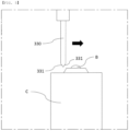
- FIG. 3 is a perspective view showing the state in which an inspection tip according to a first preferred embodiment of the present invention is located at a side of a bonding ball
- FIG. 4 is a plan view showing the state in which the inspection tip according to the first preferred embodiment of the present invention is located at the side of the bonding ball.
- the bonding state inspection apparatus includes a transfer unit 100, a thermal image inspection unit 200, and a shear inspection unit 300.
- the transfer unit 100 includes a first transfer roller 110, a second transfer roller 120, and a transfer cart 130.
- the first transfer roller 110 which is constituted by a plurality of rollers, transfers a battery module M seated on the first transfer roller 110 to a position at which a process and inspection are performed.
- the battery module M may include a plurality of cylindrical battery cells C and a module case configured to receive the plurality of cylindrical battery cells C.
- Each of the cylindrical battery cells C includes a cell case configured to receive an electrode assembly, the cell case being electrically connected to a negative electrode lead of the electrode assembly, and a top cap located at an upper part of the cell case.
- the top cap is not electrically conducted to the cell case due to an insulation member (not shown) and is electrically connected to a positive electrode lead of the electrode assembly, whereby the top cap functions as a positive electrode terminal.
- An upper surface of the cell case is located along an outer circumference of the top cap in the state in which the insulation member is interposed between the cell case and the top cap such that the cell case and the top cap are fixed to each other. It is preferable for the top cap to protrude farther than the upper surface of the cell case, and it is more preferable for a positive electrode terminal protruding upwards to be further provided at the center of the top cap.
- the electrode assembly include a cell assembly and a lead
- the cell assembly may be a jelly-roll type cell assembly, which is configured to have a structure in which a long sheet type positive electrode and a long sheet type negative electrode are wound in the state in which a separator is interposed therebetween, a stacked type cell assembly including unit cells, each of which is configured to have a structure in which a rectangular positive electrode and a rectangular negative electrode are stacked in the state in which a separator is interposed therebetween, a stacked and folded type cell assembly, which is configured to have a structure in which unit cells are wound using a long separation film, or a laminated and stacked type cell assembly, which is configured to have a structure in which unit cells are stacked in the state in which a separator is interposed therebetween and are then attached to each other; however, the present invention is not limited thereto.
- the positive electrode of the cell assembly and the top cap are directly or indirectly connected to each other via the positive electrode lead, and the negative electrode lead is electrically connected to the cell case.
- the electrode assembly constituting the cylindrical battery cell described above is a generally known construction, and therefore a more detailed description thereof will be omitted.
- the second transfer roller 120 is located in a direction perpendicular to the first transfer roller 110 and is located behind the vertical position of the shear inspection unit 300, whereby it is possible to change a movement path for the battery module M determined to be defective as the result of inspection performed by the shear inspection unit 300.
- the second transfer roller 120 may be formed between the plurality of rollers of the first transfer roller 110 and may be moved upwards and downwards by a predetermined distance in a vertical direction. At ordinary times, the second transfer roller may be in a descent state, and when change of the movement path for the battery module M determined to be defective is necessary, the second transfer roller may be moved upwards, may transfer the battery module, and may be moved downwards.
- the transfer cart 130 allows the battery module M deviating from the movement path of the first transfer roller 110 by the second transfer roller 120 to be seated thereon such that the battery module is excluded from a manufacturing process.
- the transfer cart may be a shelf or support with wheels; however, the shape of the transfer cart is not particularly restricted as long as it is possible to exclude the battery module M transferred by the second transfer roller 120 from the manufacturing process.
- the thermal image inspection unit 200 includes a photographing portion 210 and an illuminating portion 220.
- the photographing portion 210 may be a thermal imaging camera, and scans an upper surface of the battery module M transferred along an upper surface of the first transfer roller 110 to measure the temperature of bonding balls B, and transmits the position of any bonding ball B deviating from a normal range to a control device.
- the illuminating portion 220 is provided at a position horizontally parallel to the photographing portion 210 so as to be spaced apart therefrom by a predetermined distance, and illuminates the upper surface of the battery module M such that the photographing portion 210 can more accurately measure the temperature of the bonding balls B.
- the shear inspection unit 300 includes a moving shaft 310, a body portion 320, an inspection tip 330, and a displacement sensor 340.
- the moving shaft 310 has a predetermined length in a direction perpendicular to the battery module M and is located above the first transfer roller 110.
- the moving shaft 310 may be moved in a direction parallel to a transfer direction of the battery module M and in a direction perpendicular to the transfer direction of the battery module M.
- the body portion 320 is attached to a lower surface of the moving shaft 310 so as to be movable in a longitudinal direction of the moving shaft 310.
- the body portion 320 may be moved by the moving shaft 310 in a forward-rearward direction, a leftward-rightward direction, and an upward-downward direction.
- the inspection tip 330 may be a post protruding from a lower surface of the body portion 320 by a predetermined length. It is preferable for an inclined potion 331 inclined at a predetermined angle to be formed at a lower part of the inspection tip 330. The reason for this is that, when the inspection tip is moved downwards in order to apply shear force to the bonding ball B, it is possible to prevent contact between the inspection tip and another component, such as a busbar.
- the inspection tip 330 is preferable for the inspection tip 330 to be made of an insulated metal material. The reason for this is that, when shear force is applied to the bonding ball B, it is possible to prevent the occurrence of short circuit as the result of electrical conduction due to contact.
- the displacement sensor 340 may be located at a side surface of the body portion 320 and may measure the distance from the battery module M to prevent downward movement of the inspection tip 330 more than necessary, thereby preventing pressure from being applied to a battery cell C.
- the displacement sensor 340 may be a laser displacement sensor; however the displacement sensor is not particularly restricted as long as it is possible to recognize the distance between the inspection tip 330 and the battery cell C.
- FIG. 5 is a plan view showing the state in which an inspection tip according to a second preferred embodiment of the present invention is located at the side of the bonding ball.
- the bonding state inspection apparatus according to the second preferred embodiment of the present invention is identical in construction to the bonding state inspection apparatus according to the first embodiment described with reference to FIGS. 1 to 4 except for the shape of a lower part of the inspection tip, and therefore a description of the identical components will be omitted.
- an inclined portion 331 inclined at a predetermined angle is formed at each of opposite sides of a lower part of the inspection tip 330.
- FIG. 6 is a flowchart showing a bonding state inspection method according to a preferred embodiment of the present invention.
- the bonding state inspection method includes a first step of transferring a battery module M, a second step of inspecting an upper surface of the battery module M through the thermal image inspection unit 200, a third step of locating the inspection tip 330 of the shear inspection unit 300 at a position determined to be defective after inspection through the thermal image inspection unit 200, a fourth step of applying shear force to a bonding ball B through the inspection tip 330, and a fifth step of transferring the battery module M along the first transfer roller 110 when the bonding ball B is normal and removing the battery module through the second transfer roller 120 when the bonding ball is defective.
- the first step of transferring the battery module M is a step of transferring the battery module M to an inspection position through the first transfer roller 110 in order to inspect the battery module.
- the second step of inspecting the upper surface of the battery module M through the thermal image inspection unit 200 is a step of scanning the upper surface of the battery module M when the transferred battery module M passes under the photographing portion 210 to measure the temperature of the bonding ball B in order to determine whether the bonding ball is defective.
- the battery module B is charged and discharged before the second step, whereby the temperature of the bonding ball B is increased.
- the temperature of the bonding ball B having the increased temperature is measured by the photographing portion 210, and the measured temperature of the bonding ball is compared with the temperature of the bonding ball B before charging and discharging to calculate the difference between the temperature before charging and discharging and the temperature after charging and discharging.
- Whether the bonding ball B is defective is determined by checking whether the temperature difference of the bonding ball is within a normal range. At this time, when the temperature difference of the bonding ball B in a normal state is 0.66°C to 1.38°C for the positive electrode and 1.59°C to 3.19°C for the negative electrode at the time of charging and 1.12°C to 2.27°C for the positive electrode at the time of discharging, it may be determined that the bonding ball is normal.
- the bonding ball When the bonding ball is defective, e.g. when bonding is not performed, less than the lower limit of the temperature difference may be measured, and when weak bonding is performed, greater than the upper limit of the temperature difference may be measured.
- the temperature difference within the normal range is a value that can be changed depending on the kind of the battery module and electric power at the time of charging and discharging.
- the third step of locating the inspection tip 330 of the shear inspection unit 300 at the position determined to be defective after inspection through the thermal image inspection unit 200 is a step of locating the inspection tip 330 at the side of the bonding ball B determined to be defective in the second step so as to be spaced apart therefrom by a predetermined distance.
- the fourth step of applying shear force to the bonding ball B through the inspection tip 330 is a step of moving the inspection tip 330 located at the side of the bonding ball B in the third step in a direction toward the bonding ball B and applying shear force to a side surface of the bonding ball B to determine whether the bonding ball is defective.
- the fifth step of transferring the battery module M using the first transfer roller 110 when the bonding ball B is normal and removing the battery module using the second transfer roller 120 when the bonding ball is defective is a step of transferring the battery module M using the first transfer roller 110 when the bonding ball is normal after shear inspection in the fourth step and deviating the battery module M from a transfer direction of the first transfer roller 110 using the second transfer roller 120 so as to be seated in the transfer cart 130 and to be removed from the manufacturing process when the bonding ball is defective.
Landscapes
- Chemical & Material Sciences (AREA)
- Engineering & Computer Science (AREA)
- General Physics & Mathematics (AREA)
- Physics & Mathematics (AREA)
- General Health & Medical Sciences (AREA)
- Pathology (AREA)
- Immunology (AREA)
- Health & Medical Sciences (AREA)
- Life Sciences & Earth Sciences (AREA)
- Analytical Chemistry (AREA)
- Biochemistry (AREA)
- General Chemical & Material Sciences (AREA)
- Electrochemistry (AREA)
- Chemical Kinetics & Catalysis (AREA)
- Manufacturing & Machinery (AREA)
- Mechanical Engineering (AREA)
- Quality & Reliability (AREA)
- Spectroscopy & Molecular Physics (AREA)
- Computer Vision & Pattern Recognition (AREA)
- Signal Processing (AREA)
- Battery Mounting, Suspending (AREA)
- Secondary Cells (AREA)
- Connection Of Batteries Or Terminals (AREA)
Abstract
Description
- This application claims the benefit of priority to
Korean Patent Application No. 2021-0169950 filed on December 1, 2021 - The present invention relates to a bonding state inspection apparatus and a bonding state inspection method using the same, and more particularly to a bonding state inspection apparatus capable of continuously inspecting a bonding state through automation, thereby improving work efficiency, and a bonding state inspection method using the same.
- With recent development of alternative energies due to air pollution and energy depletion caused as the result of use of fossil fuels, demand for secondary batteries capable of storing electrical energy that is produced has increased. Secondary batteries, which are capable of being charged and discharged, are widely intimately used in daily life. For example, the secondary batteries are used in mobile devices, electric vehicles, and hybrid electric vehicles.
- Required capacities of secondary batteries used as energy sources of various kinds of electronic devices inevitably used in modern society have been increased due to an increase in usage of mobile devices, increasing complexity of the mobile devices, and development of electric vehicles. In order to satisfy demand of users, a plurality of battery cells is disposed in a small-sized device, whereas a battery module including a plurality of battery cells electrically connected to each other or a battery pack including a plurality of battery modules is used in a vehicle.
- Meanwhile, a secondary battery exhibits excellent electrical properties; however, there are problems in that an active material and an electrolyte, which are components of the battery, are decomposed, thus generating heat and gas, in an abnormal operation state, such as overcharging, overdischarging, exposure to a high temperature, and electrical short circuit, whereby a battery cell adjacent thereto is affected, and therefore additional secondary damage occurs.
- For these reasons, accurate inspection of a bonding state of the secondary battery with improve process efficiency is required in order to improve safety of the secondary battery during a manufacturing process and to reduce defects.
- In conventional bonding state inspection, electrical connection between battery cells in a battery module or a battery pack is performed by wire bonding, and whether a bonding state is defective is determined through thermal image inspection.
- In addition, for the bonding determined to be defective as the result of the thermal image inspection, a worker directly checks the bonding position in a subsequent process. When the number of battery cells received in the battery module or the battery pack is increased, however, it is difficult for the worker to directly check the bonding position, whereby worker fatigue is accumulated and reliability and accuracy are deteriorated.
- (Patent Document 1)
Korean Patent Application Publication No. 2021-0065297 - The present invention has been made in view of the above problems, and it is an object of the present invention to provide a bonding state inspection apparatus capable of improving accuracy and reliability through automation of a bonding state inspection process and a bonding state inspection method using the same.
- It is another object of the present invention to provide a bonding state inspection apparatus capable of applying shear force to a bonding ball after thermal image inspection to continuously perform defect inspection, thereby improving process efficiency, and a bonding state inspection method using the same.
- A bonding state inspection apparatus according to the present invention to accomplish the above objects includes a transfer unit (100) configured to transfer a battery module (M) having a plurality of battery cells received therein, a thermal image inspection unit (200) configured to scan an upper surface of the battery module (M), and a shear inspection unit (300) configured to apply a shear force to a bonding ball (B) formed at the battery module (M).
- Also, in the bonding state inspection apparatus according to the present invention, the transfer unit (100) may include a first transfer roller (110) configured to transfer the battery module (M), a second transfer roller (120) configured to change the movement direction of the battery module (M) transferred by the first transfer roller (110), and a transfer cart (130) configured to allow the battery module (M) transferred by the second transfer roller (120) to be seated therein.
- Also, in the bonding state inspection apparatus according to the present invention, the transfer direction of the first transfer roller (110) and the transfer direction of the second transfer roller (120) may be perpendicular to each other.
- Also, in the bonding state inspection apparatus according to the present invention, the thermal image inspection unit (200) may include a photographing portion (210) constituted by a thermal imaging camera and an illuminating portion (220) located spaced apart from the photographing portion (210) by a predetermined distance.
- Also, in the bonding state inspection apparatus according to the present invention, the shear inspection unit (300) may include a moving shaft (310) having a predetermined length, a body portion (320) located under the moving shaft (310), an inspection tip (330) provided at a lower surface of the body portion (320), and a displacement sensor (340) provided at a side surface of the body portion (320).
- Also, in the bonding state inspection apparatus according to the present invention, the moving shaft (310) may be located so as to have the predetermined length in a direction perpendicular to the transfer direction of the battery module (M).
- Also, in the bonding state inspection apparatus according to the present invention, the moving shaft (310) may be movable in a direction parallel to the transfer direction of the battery module and in a direction perpendicular to the transfer direction of the battery module (M), and the body portion (320) may be movable in a longitudinal direction of the moving shaft (310).
- Also, in the bonding state inspection apparatus according to the present invention, the inspection tip (330) may include an insulated metal material.
- Also, in the bonding state inspection apparatus according to the present invention, an inclined portion (331) inclined at a predetermined angle may be formed at a lower part of the inspection tip (330).
- In addition, a bonding state inspection method according to the present invention includes a first step of transferring a battery module (M), a second step of inspecting an upper surface of the battery module (M) through the thermal image inspection unit (200), a third step of locating the inspection tip (330) of the shear inspection unit (300) at a position determined to be defective after inspection through the thermal image inspection unit (200), a fourth step of applying shear force to a bonding ball (B) through the inspection tip (330), and a fifth step of transferring the battery module (M) along the first transfer roller (110) when the bonding ball (B) is normal and removing the battery module (M) through the second transfer roller (120) when the bonding ball is defective.
- Also, the bonding state inspection method according to the present invention may further include a step of charging and discharging the battery module (M) before the second step.
- Also, in the bonding state inspection method according to the present invention, in the third step, the inspection tip (330) may be located spaced apart from a side of the bonding ball (B) by a predetermined distance.
- Also, in the bonding state inspection method according to the present invention, in the fourth step, the shear force may be applied to a side surface of the bonding ball (B).
- As is apparent from the above description, a bonding state inspection apparatus according to the present invention and a bonding state inspection method using the same have an advantage in that primary inspection by a thermal image inspection unit and secondary inspection by a shear inspection unit are successively performed, whereby process efficiency is improved.
- In addition, the bonding state inspection apparatus according to the present invention and the bonding state inspection method using the same have an advantage in that bonding state inspection is automated by the apparatus, whereby accuracy is improved and process time is reduced.
-
-
FIG. 1 is a perspective view showing a bonding state inspection apparatus according to a first preferred embodiment of the present invention. -
FIG. 2 is a plan view of a shear inspection unit according to a first preferred embodiment of the present invention when viewed from the front. -
FIG. 3 is a perspective view showing the state in which an inspection tip according to a first preferred embodiment of the present invention is located at a side of a bonding ball. -
FIG. 4 is a plan view showing the state in which the inspection tip according to the first preferred embodiment of the present invention is located at the side of the bonding ball. -
FIG. 5 is a plan view showing the state in which an inspection tip according to a second preferred embodiment of the present invention is located at the side of the bonding ball. -
FIG. 6 is a flowchart showing a bonding state inspection method according to a preferred embodiment of the present invention. - Now, preferred embodiments of the present invention will be described in detail with reference to the accompanying drawings such that the preferred embodiments of the present invention can be easily implemented by a person having ordinary skill in the art to which the present invention pertains. In describing the principle of operation of the preferred embodiments of the present invention in detail, however, a detailed description of known functions and configurations incorporated herein will be omitted when the same may obscure the subject matter of the present invention.
- In addition, the same reference numbers will be used throughout the drawings to refer to parts that perform similar functions or operations. In the case in which one part is said to be connected to another part in the entire specification, not only may the one part be directly connected to the other part, but also, the one part may be indirectly connected to the other part via a further part. In addition, that a certain element is included does not mean that other elements are excluded, but means that such elements may be further included unless mentioned otherwise.
- Hereinafter, a bonding state inspection apparatus according to the present invention and a bonding state inspection method using the same will be described with reference to the accompanying drawings.
-
FIG. 1 is a perspective view showing a bonding state inspection apparatus according to a first preferred embodiment of the present invention,FIG. 2 is a plan view of a shear inspection unit according to a first preferred embodiment of the present invention when viewed from the front,FIG. 3 is a perspective view showing the state in which an inspection tip according to a first preferred embodiment of the present invention is located at a side of a bonding ball, andFIG. 4 is a plan view showing the state in which the inspection tip according to the first preferred embodiment of the present invention is located at the side of the bonding ball. - Referring to
FIGS. 1 to 4 , the bonding state inspection apparatus according to the present invention includes atransfer unit 100, a thermalimage inspection unit 200, and ashear inspection unit 300. - First, the
transfer unit 100 includes afirst transfer roller 110, asecond transfer roller 120, and atransfer cart 130. - The
first transfer roller 110, which is constituted by a plurality of rollers, transfers a battery module M seated on thefirst transfer roller 110 to a position at which a process and inspection are performed. - Here, the battery module M may include a plurality of cylindrical battery cells C and a module case configured to receive the plurality of cylindrical battery cells C.
- Each of the cylindrical battery cells C includes a cell case configured to receive an electrode assembly, the cell case being electrically connected to a negative electrode lead of the electrode assembly, and a top cap located at an upper part of the cell case.
- The top cap is not electrically conducted to the cell case due to an insulation member (not shown) and is electrically connected to a positive electrode lead of the electrode assembly, whereby the top cap functions as a positive electrode terminal.
- An upper surface of the cell case is located along an outer circumference of the top cap in the state in which the insulation member is interposed between the cell case and the top cap such that the cell case and the top cap are fixed to each other. It is preferable for the top cap to protrude farther than the upper surface of the cell case, and it is more preferable for a positive electrode terminal protruding upwards to be further provided at the center of the top cap.
- Meanwhile, the electrode assembly include a cell assembly and a lead, and the cell assembly may be a jelly-roll type cell assembly, which is configured to have a structure in which a long sheet type positive electrode and a long sheet type negative electrode are wound in the state in which a separator is interposed therebetween, a stacked type cell assembly including unit cells, each of which is configured to have a structure in which a rectangular positive electrode and a rectangular negative electrode are stacked in the state in which a separator is interposed therebetween, a stacked and folded type cell assembly, which is configured to have a structure in which unit cells are wound using a long separation film, or a laminated and stacked type cell assembly, which is configured to have a structure in which unit cells are stacked in the state in which a separator is interposed therebetween and are then attached to each other; however, the present invention is not limited thereto.
- For a pair of leads constituted by a positive electrode lead and a negative electrode lead, the positive electrode of the cell assembly and the top cap are directly or indirectly connected to each other via the positive electrode lead, and the negative electrode lead is electrically connected to the cell case. The electrode assembly constituting the cylindrical battery cell described above is a generally known construction, and therefore a more detailed description thereof will be omitted.
- Next, the
second transfer roller 120 is located in a direction perpendicular to thefirst transfer roller 110 and is located behind the vertical position of theshear inspection unit 300, whereby it is possible to change a movement path for the battery module M determined to be defective as the result of inspection performed by theshear inspection unit 300. - Here, the
second transfer roller 120 may be formed between the plurality of rollers of thefirst transfer roller 110 and may be moved upwards and downwards by a predetermined distance in a vertical direction. At ordinary times, the second transfer roller may be in a descent state, and when change of the movement path for the battery module M determined to be defective is necessary, the second transfer roller may be moved upwards, may transfer the battery module, and may be moved downwards. - The
transfer cart 130 allows the battery module M deviating from the movement path of thefirst transfer roller 110 by thesecond transfer roller 120 to be seated thereon such that the battery module is excluded from a manufacturing process. The transfer cart may be a shelf or support with wheels; however, the shape of the transfer cart is not particularly restricted as long as it is possible to exclude the battery module M transferred by thesecond transfer roller 120 from the manufacturing process. - Next, the thermal
image inspection unit 200 includes a photographingportion 210 and an illuminatingportion 220. - The photographing
portion 210 may be a thermal imaging camera, and scans an upper surface of the battery module M transferred along an upper surface of thefirst transfer roller 110 to measure the temperature of bonding balls B, and transmits the position of any bonding ball B deviating from a normal range to a control device. - The illuminating
portion 220 is provided at a position horizontally parallel to the photographingportion 210 so as to be spaced apart therefrom by a predetermined distance, and illuminates the upper surface of the battery module M such that the photographingportion 210 can more accurately measure the temperature of the bonding balls B. - The
shear inspection unit 300 includes a movingshaft 310, abody portion 320, aninspection tip 330, and adisplacement sensor 340. - The moving
shaft 310 has a predetermined length in a direction perpendicular to the battery module M and is located above thefirst transfer roller 110. The movingshaft 310 may be moved in a direction parallel to a transfer direction of the battery module M and in a direction perpendicular to the transfer direction of the battery module M. - The
body portion 320 is attached to a lower surface of the movingshaft 310 so as to be movable in a longitudinal direction of the movingshaft 310. Thebody portion 320 may be moved by the movingshaft 310 in a forward-rearward direction, a leftward-rightward direction, and an upward-downward direction. - The
inspection tip 330 may be a post protruding from a lower surface of thebody portion 320 by a predetermined length. It is preferable for aninclined potion 331 inclined at a predetermined angle to be formed at a lower part of theinspection tip 330. The reason for this is that, when the inspection tip is moved downwards in order to apply shear force to the bonding ball B, it is possible to prevent contact between the inspection tip and another component, such as a busbar. - Also, it is preferable for the
inspection tip 330 to be made of an insulated metal material. The reason for this is that, when shear force is applied to the bonding ball B, it is possible to prevent the occurrence of short circuit as the result of electrical conduction due to contact. - The
displacement sensor 340 may be located at a side surface of thebody portion 320 and may measure the distance from the battery module M to prevent downward movement of theinspection tip 330 more than necessary, thereby preventing pressure from being applied to a battery cell C. Thedisplacement sensor 340 may be a laser displacement sensor; however the displacement sensor is not particularly restricted as long as it is possible to recognize the distance between theinspection tip 330 and the battery cell C. -
FIG. 5 is a plan view showing the state in which an inspection tip according to a second preferred embodiment of the present invention is located at the side of the bonding ball. - Referring to
FIG. 5 , the bonding state inspection apparatus according to the second preferred embodiment of the present invention is identical in construction to the bonding state inspection apparatus according to the first embodiment described with reference toFIGS. 1 to 4 except for the shape of a lower part of the inspection tip, and therefore a description of the identical components will be omitted. - In the
inspection tip 330 according to the second preferred embodiment of the present invention, aninclined portion 331 inclined at a predetermined angle is formed at each of opposite sides of a lower part of theinspection tip 330. When theinspection tip 330 is moved downwards and is located at set coordinates, therefore, it is possible to prevent contact between the inspection tip and another component, such as the busbar or the module case, in opposite directions. -
FIG. 6 is a flowchart showing a bonding state inspection method according to a preferred embodiment of the present invention. - Referring to
FIG. 6 , the bonding state inspection method according to the preferred embodiment of the present invention includes a first step of transferring a battery module M, a second step of inspecting an upper surface of the battery module M through the thermalimage inspection unit 200, a third step of locating theinspection tip 330 of theshear inspection unit 300 at a position determined to be defective after inspection through the thermalimage inspection unit 200, a fourth step of applying shear force to a bonding ball B through theinspection tip 330, and a fifth step of transferring the battery module M along thefirst transfer roller 110 when the bonding ball B is normal and removing the battery module through thesecond transfer roller 120 when the bonding ball is defective. - The first step of transferring the battery module M is a step of transferring the battery module M to an inspection position through the
first transfer roller 110 in order to inspect the battery module. - The second step of inspecting the upper surface of the battery module M through the thermal
image inspection unit 200 is a step of scanning the upper surface of the battery module M when the transferred battery module M passes under the photographingportion 210 to measure the temperature of the bonding ball B in order to determine whether the bonding ball is defective. - Here, the battery module B is charged and discharged before the second step, whereby the temperature of the bonding ball B is increased. The temperature of the bonding ball B having the increased temperature is measured by the photographing
portion 210, and the measured temperature of the bonding ball is compared with the temperature of the bonding ball B before charging and discharging to calculate the difference between the temperature before charging and discharging and the temperature after charging and discharging. - Whether the bonding ball B is defective is determined by checking whether the temperature difference of the bonding ball is within a normal range. At this time, when the temperature difference of the bonding ball B in a normal state is 0.66°C to 1.38°C for the positive electrode and 1.59°C to 3.19°C for the negative electrode at the time of charging and 1.12°C to 2.27°C for the positive electrode at the time of discharging, it may be determined that the bonding ball is normal.
- In addition, when the temperature difference is 1.12°C to 2.27°C for the positive electrode and 0.88°C to 2.20°C for the negative electrode at the time of discharging, it may be determined that the bonding ball is normal.
- When the bonding ball is defective, e.g. when bonding is not performed, less than the lower limit of the temperature difference may be measured, and when weak bonding is performed, greater than the upper limit of the temperature difference may be measured.
- Here, the temperature difference within the normal range is a value that can be changed depending on the kind of the battery module and electric power at the time of charging and discharging.
- The third step of locating the
inspection tip 330 of theshear inspection unit 300 at the position determined to be defective after inspection through the thermalimage inspection unit 200 is a step of locating theinspection tip 330 at the side of the bonding ball B determined to be defective in the second step so as to be spaced apart therefrom by a predetermined distance. - The fourth step of applying shear force to the bonding ball B through the
inspection tip 330 is a step of moving theinspection tip 330 located at the side of the bonding ball B in the third step in a direction toward the bonding ball B and applying shear force to a side surface of the bonding ball B to determine whether the bonding ball is defective. - The fifth step of transferring the battery module M using the
first transfer roller 110 when the bonding ball B is normal and removing the battery module using thesecond transfer roller 120 when the bonding ball is defective is a step of transferring the battery module M using thefirst transfer roller 110 when the bonding ball is normal after shear inspection in the fourth step and deviating the battery module M from a transfer direction of thefirst transfer roller 110 using thesecond transfer roller 120 so as to be seated in thetransfer cart 130 and to be removed from the manufacturing process when the bonding ball is defective. - Although the specific details of the present invention have been described in detail, those skilled in the art will appreciate that the detailed description thereof discloses only preferred embodiments of the present invention and thus does not limit the scope of the present invention. Accordingly, those skilled in the art will appreciate that various changes and modifications are possible, without departing from the category and the technical idea of the present invention, and it will be obvious that such changes and modifications fall within the scope of the appended claims.
-
- 100:
- Transfer unit
- 110:
- Transfer roller
- 120:
- Second transfer roller
- 130:
- Transfer cart
- 200:
- Thermal image inspection unit
- 210:
- Photographing portion
- 220:
- Illuminating portion
- 300:
- Shear inspection unit
- 310:
- Moving shaft
- 320:
- Body portion
- 330:
- Inspection tip
- 331:
- Inclined portion
- 340:
- Displacement sensor
- M:
- Battery module
- C:
- Battery cell
- B:
- Bonding ball
Claims (13)
- A bonding state inspection apparatus comprising:a transfer unit configured to transfer a battery module having a plurality of battery cells received therein;a thermal image inspection unit configured to scan an upper surface of the battery module; anda shear inspection unit configured to apply a shear force to a bonding ball formed at the battery module.
- The bonding state inspection apparatus according to claim 1, wherein the transfer unit comprises:a first transfer roller configured to transfer the battery module;a second transfer roller configured to change a movement direction of the battery module transferred by the first transfer roller; anda transfer cart configured to allow the battery module transferred by the second transfer roller to be seated therein.
- The bonding state inspection apparatus according to claim 2, wherein a transfer direction of the first transfer roller and a transfer direction of the second transfer roller are perpendicular to each other.
- The bonding state inspection apparatus according to claim 1, wherein the thermal image inspection unit comprises:a photographing portion constituted by a thermal imaging camera; andan illuminating portion located spaced apart from the photographing portion by a predetermined distance.
- The bonding state inspection apparatus according to claim 1, wherein the shear inspection unit comprises:a moving shaft having a predetermined length;a body portion located under the moving shaft;an inspection tip provided at a lower surface of the body portion; anda displacement sensor provided at a side surface of the body portion.
- The bonding state inspection apparatus according to claim 5, wherein the moving shaft is located so as to have the predetermined length in a direction perpendicular to a transfer direction of the battery module.
- The bonding state inspection apparatus according to claim 6, wherein the moving shaft is movable in a direction parallel to the transfer direction of the battery module and in a direction perpendicular to the transfer direction of the battery module, and
wherein the body portion is movable in a longitudinal direction of the moving shaft. - The bonding state inspection apparatus according to claim 5, wherein the inspection tip includes an insulated metal material.
- The bonding state inspection apparatus according to claim 5, wherein an inclined portion inclined at a predetermined angle is formed at a lower part of the inspection tip.
- A bonding state inspection method using the bonding state inspection apparatus according to any one of claims 1 to 9, the bonding state inspection method comprising:a first step of transferring a battery module;a second step of inspecting an upper surface of the battery module through the thermal image inspection unit;a third step of locating the inspection tip of the shear inspection unit at a position determined to be defective after inspection through the thermal image inspection unit;a fourth step of applying shear force to a bonding ball through the inspection tip; anda fifth step of transferring the battery module along the first transfer roller when the bonding ball is normal and removing the battery module through the second transfer roller when the bonding ball is defective.
- The bonding state inspection method according to claim 10, further comprising a step of charging and discharging the battery module before the second step.
- The bonding state inspection method according to claim 10, wherein, in the third step, the inspection tip is located spaced apart from a side of the bonding ball by a predetermined distance.
- The bonding state inspection method according to claim 12, wherein, in the fourth step, the shear force is applied to a side surface of the bonding ball.
Applications Claiming Priority (2)
| Application Number | Priority Date | Filing Date | Title |
|---|---|---|---|
| KR1020210169950A KR20230082229A (en) | 2021-12-01 | 2021-12-01 | Bonding State Inspection Device And Bonding State Inspection Method Using The Same |
| PCT/KR2022/018389 WO2023101287A1 (en) | 2021-12-01 | 2022-11-21 | Bonding state inspection apparatus and bonding state inspection method using same |
Publications (3)
| Publication Number | Publication Date |
|---|---|
| EP4310986A1 true EP4310986A1 (en) | 2024-01-24 |
| EP4310986A4 EP4310986A4 (en) | 2025-04-09 |
| EP4310986B1 EP4310986B1 (en) | 2026-02-18 |
Family
ID=86612531
Family Applications (1)
| Application Number | Title | Priority Date | Filing Date |
|---|---|---|---|
| EP22901645.6A Active EP4310986B1 (en) | 2021-12-01 | 2022-11-21 | Bonding state inspection apparatus and bonding state inspection method using same |
Country Status (7)
| Country | Link |
|---|---|
| US (1) | US12625045B2 (en) |
| EP (1) | EP4310986B1 (en) |
| JP (1) | JP7680131B2 (en) |
| KR (1) | KR20230082229A (en) |
| CN (1) | CN117099243A (en) |
| ES (1) | ES3065170T3 (en) |
| WO (1) | WO2023101287A1 (en) |
Families Citing this family (1)
| Publication number | Priority date | Publication date | Assignee | Title |
|---|---|---|---|---|
| CN116973246A (en) * | 2022-04-21 | 2023-10-31 | 先进科技新加坡有限公司 | Method and apparatus for shear testing of interconnect bonds |
Family Cites Families (19)
| Publication number | Priority date | Publication date | Assignee | Title |
|---|---|---|---|---|
| KR100745586B1 (en) | 2001-05-07 | 2007-08-02 | 삼성전자주식회사 | Battery Inspection Device |
| JP4242086B2 (en) | 2001-08-09 | 2009-03-18 | 三菱電機株式会社 | Wire bond inspection apparatus and wire bond inspection method |
| JP3855741B2 (en) * | 2001-11-09 | 2006-12-13 | 株式会社日立製作所 | Semiconductor device joint strength evaluation method, evaluation device, and semiconductor device |
| JP2004311623A (en) | 2003-04-04 | 2004-11-04 | Matsushita Electric Ind Co Ltd | Inspection method and inspection device for electronic components |
| GB0411057D0 (en) | 2004-05-18 | 2004-06-23 | Dage Prec Ind Ltd | Test apparatus |
| US7905152B2 (en) | 2006-02-17 | 2011-03-15 | Nordson Corporation | Shear test apparatus and method |
| KR101152645B1 (en) * | 2007-06-14 | 2012-06-04 | 주식회사 엘지화학 | Method of Inspecting Welding State on Welding Portion of Cell |
| JP6415229B2 (en) | 2014-10-06 | 2018-10-31 | 新栄電子計測器株式会社 | Solar cell module inspection device and solar cell module inspection vehicle |
| KR102072481B1 (en) | 2016-03-23 | 2020-02-25 | 주식회사 엘지화학 | Method of Inspecting Welding State Using Pressure Gauge |
| JP2018010770A (en) | 2016-07-13 | 2018-01-18 | 株式会社豊田自動織機 | Inspection method of battery module and inspection apparatus of battery module |
| JP6631482B2 (en) | 2016-11-21 | 2020-01-15 | トヨタ自動車株式会社 | Battery inspection method |
| KR101977305B1 (en) | 2017-06-12 | 2019-05-13 | (주)티에스이 | Themal testing apparatus for flatpanel display |
| CN109540967A (en) * | 2017-11-30 | 2019-03-29 | 蜂巢能源科技有限公司 | Weld quality prediction system and method |
| KR101909861B1 (en) * | 2018-05-31 | 2018-10-18 | 윤남수 | Apparatus for transferring of glass panel |
| KR102386324B1 (en) | 2019-06-11 | 2022-04-14 | 주식회사 엘지에너지솔루션 | Inspection device and method for secondary battery |
| KR102741987B1 (en) | 2019-11-27 | 2024-12-13 | 주식회사 엘지에너지솔루션 | Inspecting Method of Weld Zone Using Themovision |
| KR102889710B1 (en) * | 2020-04-13 | 2025-11-21 | 주식회사 엘지에너지솔루션 | Welding inspection device and inspection method for secondary battery |
| KR102294189B1 (en) | 2021-04-16 | 2021-08-27 | 주식회사 성안테크 | Inspection device to detect welding status of missing or folding tab of battery electrode |
| KR102886268B1 (en) | 2021-07-06 | 2025-11-13 | 주식회사 엘지에너지솔루션 | Smart high temperature aging system |
-
2021
- 2021-12-01 KR KR1020210169950A patent/KR20230082229A/en active Pending
-
2022
- 2022-11-21 JP JP2023555393A patent/JP7680131B2/en active Active
- 2022-11-21 WO PCT/KR2022/018389 patent/WO2023101287A1/en not_active Ceased
- 2022-11-21 CN CN202280022382.0A patent/CN117099243A/en active Pending
- 2022-11-21 US US18/288,145 patent/US12625045B2/en active Active
- 2022-11-21 ES ES22901645T patent/ES3065170T3/en active Active
- 2022-11-21 EP EP22901645.6A patent/EP4310986B1/en active Active
Also Published As
| Publication number | Publication date |
|---|---|
| EP4310986A4 (en) | 2025-04-09 |
| JP7680131B2 (en) | 2025-05-20 |
| US12625045B2 (en) | 2026-05-12 |
| JP2024509463A (en) | 2024-03-01 |
| ES3065170T3 (en) | 2026-05-04 |
| CN117099243A (en) | 2023-11-21 |
| KR20230082229A (en) | 2023-06-08 |
| US20240210293A1 (en) | 2024-06-27 |
| EP4310986B1 (en) | 2026-02-18 |
| WO2023101287A1 (en) | 2023-06-08 |
Similar Documents
| Publication | Publication Date | Title |
|---|---|---|
| EP3565052B1 (en) | Electrode plate aligned state inspection system and method | |
| US12066503B2 (en) | Bus bar for battery cell connection, battery pack, and manufacturing method therefor | |
| EP4006533A1 (en) | Weld zone detection method using thermal image sensing | |
| EP4026651B1 (en) | Welding quality inspection device | |
| JP2023521313A (en) | Electrode lead bending and welding device and electrode lead welding method using the same | |
| CN116867602A (en) | Weld inspection device including thermal imaging camera | |
| KR20200109040A (en) | Short testing apparatus and checking method for deformation of electrode-tab using the short testing apparatus | |
| US20240302425A1 (en) | Secondary Battery Cell Insulation Test Apparatus and Method Using the Same | |
| EP4310986B1 (en) | Bonding state inspection apparatus and bonding state inspection method using same | |
| US12298278B2 (en) | Battery cell weld portion inspection apparatus and battery cell weld portion inspection method using the same | |
| KR20150050116A (en) | Short measuring apparatus of unit cell | |
| KR102772444B1 (en) | A detecting method of welding defect | |
| EP4306942B1 (en) | Nondestructive wire bonding inspection method | |
| EP4287347A1 (en) | Apparatus and method for inspecting electrode cell | |
| KR102625279B1 (en) | Detecting apparatus for electrode of secondary battery | |
| US12422500B2 (en) | Method for inspecting a power storage device, method for manufacturing a power storage device, and method for manufacturing a device stack | |
| US20240302437A1 (en) | Secondary Battery Cell Insulation Test Apparatus and Method Using the Same | |
| KR102952010B1 (en) | Stack cell for being easy to identification of separator, separator inspection apparatus and method thereof | |
| US20260074265A1 (en) | Assembly apparatus and assembly method | |
| KR20260045352A (en) | Secondary battery including cell lead having gap measuring hole and welding method for cell lead | |
| KR20250072831A (en) | Inspection device of electrode assembly and inspection method using the same | |
| KR20260071581A (en) | Apparatus for checking battery and checking method of battery | |
| KR20230115923A (en) | battery module inspection method | |
| EP4671797A1 (en) | METHOD AND DEVICE FOR MONITORING SELF-DISCHARGE PHENOMENA OF ELECTROCHEMICAL CELLS | |
| KR20250149060A (en) | Apparatus and method for inspecting electrode stack |
Legal Events
| Date | Code | Title | Description |
|---|---|---|---|
| STAA | Information on the status of an ep patent application or granted ep patent |
Free format text: STATUS: THE INTERNATIONAL PUBLICATION HAS BEEN MADE |
|
| PUAI | Public reference made under article 153(3) epc to a published international application that has entered the european phase |
Free format text: ORIGINAL CODE: 0009012 |
|
| STAA | Information on the status of an ep patent application or granted ep patent |
Free format text: STATUS: REQUEST FOR EXAMINATION WAS MADE |
|
| 17P | Request for examination filed |
Effective date: 20231019 |
|
| AK | Designated contracting states |
Kind code of ref document: A1 Designated state(s): AL AT BE BG CH CY CZ DE DK EE ES FI FR GB GR HR HU IE IS IT LI LT LU LV MC ME MK MT NL NO PL PT RO RS SE SI SK SM TR |
|
| DAV | Request for validation of the european patent (deleted) | ||
| DAX | Request for extension of the european patent (deleted) | ||
| A4 | Supplementary search report drawn up and despatched |
Effective date: 20250312 |
|
| RIC1 | Information provided on ipc code assigned before grant |
Ipc: B23K 31/12 20060101ALI20250306BHEP Ipc: G01N 21/88 20060101ALI20250306BHEP Ipc: H01M 10/44 20060101ALI20250306BHEP Ipc: H01M 10/42 20060101AFI20250306BHEP |
|
| GRAP | Despatch of communication of intention to grant a patent |
Free format text: ORIGINAL CODE: EPIDOSNIGR1 |
|
| STAA | Information on the status of an ep patent application or granted ep patent |
Free format text: STATUS: GRANT OF PATENT IS INTENDED |
|
| INTG | Intention to grant announced |
Effective date: 20250923 |
|
| P01 | Opt-out of the competence of the unified patent court (upc) registered |
Free format text: CASE NUMBER: UPC_APP_8741_4310986/2025 Effective date: 20251002 |
|
| GRAS | Grant fee paid |
Free format text: ORIGINAL CODE: EPIDOSNIGR3 |
|
| GRAA | (expected) grant |
Free format text: ORIGINAL CODE: 0009210 |
|
| STAA | Information on the status of an ep patent application or granted ep patent |
Free format text: STATUS: THE PATENT HAS BEEN GRANTED |
|
| AK | Designated contracting states |
Kind code of ref document: B1 Designated state(s): AL AT BE BG CH CY CZ DE DK EE ES FI FR GB GR HR HU IE IS IT LI LT LU LV MC ME MK MT NL NO PL PT RO RS SE SI SK SM TR |
|
| REG | Reference to a national code |
Ref country code: CH Ref legal event code: F10 Free format text: ST27 STATUS EVENT CODE: U-0-0-F10-F00 (AS PROVIDED BY THE NATIONAL OFFICE) Effective date: 20260218 Ref country code: GB Ref legal event code: FG4D |
|
| REG | Reference to a national code |
Ref country code: DE Ref legal event code: R096 Ref document number: 602022030873 Country of ref document: DE |
|
| REG | Reference to a national code |
Ref country code: IE Ref legal event code: FG4D |
|
| REG | Reference to a national code |
Ref country code: ES Ref legal event code: FG2A Ref document number: 3065170 Country of ref document: ES Kind code of ref document: T3 Effective date: 20260504 |