EP4310857A1 - Inventory management system, inventory management device, inventory management method, and inventory management program - Google Patents
Inventory management system, inventory management device, inventory management method, and inventory management program Download PDFInfo
- Publication number
- EP4310857A1 EP4310857A1 EP22771329.4A EP22771329A EP4310857A1 EP 4310857 A1 EP4310857 A1 EP 4310857A1 EP 22771329 A EP22771329 A EP 22771329A EP 4310857 A1 EP4310857 A1 EP 4310857A1
- Authority
- EP
- European Patent Office
- Prior art keywords
- inventory
- medical
- inventory management
- medical device
- electrocardiograph
- Prior art date
- Legal status (The legal status is an assumption and is not a legal conclusion. Google has not performed a legal analysis and makes no representation as to the accuracy of the status listed.)
- Pending
Links
Images









Classifications
-
- G—PHYSICS
- G16—INFORMATION AND COMMUNICATION TECHNOLOGY [ICT] SPECIALLY ADAPTED FOR SPECIFIC APPLICATION FIELDS
- G16H—HEALTHCARE INFORMATICS, i.e. INFORMATION AND COMMUNICATION TECHNOLOGY [ICT] SPECIALLY ADAPTED FOR THE HANDLING OR PROCESSING OF MEDICAL OR HEALTHCARE DATA
- G16H40/00—ICT specially adapted for the management or administration of healthcare resources or facilities; ICT specially adapted for the management or operation of medical equipment or devices
- G16H40/20—ICT specially adapted for the management or administration of healthcare resources or facilities; ICT specially adapted for the management or operation of medical equipment or devices for the management or administration of healthcare resources or facilities, e.g. managing hospital staff or surgery rooms
-
- G—PHYSICS
- G06—COMPUTING OR CALCULATING; COUNTING
- G06Q—INFORMATION AND COMMUNICATION TECHNOLOGY [ICT] SPECIALLY ADAPTED FOR ADMINISTRATIVE, COMMERCIAL, FINANCIAL, MANAGERIAL OR SUPERVISORY PURPOSES; SYSTEMS OR METHODS SPECIALLY ADAPTED FOR ADMINISTRATIVE, COMMERCIAL, FINANCIAL, MANAGERIAL OR SUPERVISORY PURPOSES, NOT OTHERWISE PROVIDED FOR
- G06Q10/00—Administration; Management
- G06Q10/08—Logistics, e.g. warehousing, loading or distribution; Inventory or stock management
- G06Q10/087—Inventory or stock management, e.g. order filling, procurement or balancing against orders
-
- G—PHYSICS
- G16—INFORMATION AND COMMUNICATION TECHNOLOGY [ICT] SPECIALLY ADAPTED FOR SPECIFIC APPLICATION FIELDS
- G16H—HEALTHCARE INFORMATICS, i.e. INFORMATION AND COMMUNICATION TECHNOLOGY [ICT] SPECIALLY ADAPTED FOR THE HANDLING OR PROCESSING OF MEDICAL OR HEALTHCARE DATA
- G16H40/00—ICT specially adapted for the management or administration of healthcare resources or facilities; ICT specially adapted for the management or operation of medical equipment or devices
- G16H40/40—ICT specially adapted for the management or administration of healthcare resources or facilities; ICT specially adapted for the management or operation of medical equipment or devices for the management of medical equipment or devices, e.g. scheduling maintenance or upgrades
-
- G—PHYSICS
- G16—INFORMATION AND COMMUNICATION TECHNOLOGY [ICT] SPECIALLY ADAPTED FOR SPECIFIC APPLICATION FIELDS
- G16H—HEALTHCARE INFORMATICS, i.e. INFORMATION AND COMMUNICATION TECHNOLOGY [ICT] SPECIALLY ADAPTED FOR THE HANDLING OR PROCESSING OF MEDICAL OR HEALTHCARE DATA
- G16H40/00—ICT specially adapted for the management or administration of healthcare resources or facilities; ICT specially adapted for the management or operation of medical equipment or devices
- G16H40/60—ICT specially adapted for the management or administration of healthcare resources or facilities; ICT specially adapted for the management or operation of medical equipment or devices for the operation of medical equipment or devices
Definitions
- the present invention relates to inventory management systems, inventory management devices, inventory management methods, and inventory management programs.
- it is an object to reduce a load of inventory management.
- an inventory management system has an inventory management device and a terminal device, and the inventory management device includes an inventory status generation unit configured to generate information indicating an inventory status of a medical device for each of a plurality of medical institutions, by referring to a required inventory storage unit storing information indicating a required inventory quantity of the medical device for each of the plurality of medical institutions, and a state management storage unit storing state management information associating a unique ID of the medical device dispatched to one medical institution with a collection status of the medical device paid out from the one medical institution to a patient for each of the plurality of medical institutions, and an output unit configured to output the information indicating the inventory status to the terminal device.
- the load of inventory management can be reduced.
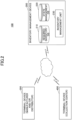
- FIG. 1 is a diagram illustrating an outline of an inventory management system according to a first embodiment.
- an electrocardiograph 10 will be described as an example of a medical device that is a target of inventory management by an inventory management system 100 according to the present embodiment.
- the electrocardiograph 10 is manufactured and/or sold by a manufacturer and/or distributor 1.
- the manufacturer and/or distributor 1 refers to a supplier who distributes to medical institutions, and does not indicate a distinction among a manufacturer, a manufacturer and distributor, and a distributor as defined in the Pharmaceutical and Medical Device Act.
- the electrocardiograph 10 is a single-use medical device that is collected and discarded after being worn on a body of a patient for a certain period of time.
- the electrocardiograph 10 includes a storage device that stores measured electrocardiogram waveform data or the like.
- identification information for identifying the electrocardiograph 10 is stored in the storage device or the like of the electrocardiograph 10.
- the identification information for uniquely identifying the electrocardiograph 10 is stored in the storage device of all of the electrocardiographs 10 manufactured by the manufacturer and/or distributor 1.
- a method of assigning the identification information to the electrocardiograph 10 is not limited to the method described above.
- the method of assigning the identification information to the electrocardiograph 10 may be any method as long as the electrocardiograph 10 can be associated with the identification information for uniquely identifying the electrocardiograph 10.
- the identification information (unique ID) for uniquely identifying the electrocardiograph 10 may also be referred to as a device ID.
- the electrocardiograph 10 having the device ID assigned thereto is dispatched from the manufacturer and/or distributor 1 to a medical institution 2 (procedure S1).
- the inventory management system 100 receives the device ID of the dispatched electrocardiograph 10 and the identification information for uniquely identifying the medical institution that are input from the manufacturer and/or distributor 1, and holds information associating the device ID and the identification information of the medical institution (procedure S2).
- the identification information for uniquely identifying the medical institution may also be referred to as a medical institution ID.
- the electrocardiograph 10 is used on a patient P (procedure S3), and the patient P wears the electrocardiograph 10 to collect the electrocardiogram waveform data from the electrocardiograph 10.
- the patient P returns the electrocardiograph 10 to a collection center 3 by post or the like (procedure S4).
- the patient P provides the collection center 3 with activity record information 11 indicating the patient's own activity contents during the period of time in which the electrocardiograph 10 is worn by the patient P.
- the activity record information 11 is a document or the like, for example, and may be forwarded by post from the patient P to the collection center 3, together with the electrocardiograph 10.
- the electrocardiograph 10 may be returned from the patient P who used the electrocardiograph 10 to the medical institution 2, and may be forwarded by post from the medical institution 2 to the collection center 3.
- the collection center 3 reads the electrocardiogram waveform and the device ID stored in the storage device of the used electrocardiograph 10, and thereafter notifies the device ID of the electrocardiograph 10 to the inventory management system 100 (procedure S5).
- the inventory management system 100 detects that an inventory of the electrocardiograph 10 in the medical institution 2 decreased by one when notified of the device ID.
- the inventory management system 100 instructs the manufacturer and/or distributor 1 to replenish the inventory of the electrocardiograph 10 in the medical institution 2 (procedure S6).
- a timing at which the inventory management system 100 instructs the manufacturer and/or distributor 1 to replenish the inventory may be arbitrarily determined between the manufacturer and/or distributor 1 and the medical institution 2. More particularly, a replenish instruction to replenish the inventory may be issued in units of a certain period of time, for example.
- the device ID for identifying the electrocardiograph 10 is assigned to the single-use electrocardiograph 10, and the device ID and the medical institution ID for identifying the medical institution to which the electrocardiograph 10 is dispatched are managed in association with each other.
- a user of the inventory management system 100 can grasp a dispatch destination of the electrocardiograph 10.
- the inventory management system 100 when the electrocardiograph 10 is collected and discarded, receives a notification indicating that the electrocardiograph 10 has been collected together with the device ID of the electrocardiograph 10, and identifies the medical institution from which the electrocardiograph 10 was collected. Accordingly, in the inventory management system 100 according to the present embodiment, the user of the inventory management system 100 can grasp usage demands of the electrocardiograph 10 in the medical institution.
- the inventory management system 100 can notify a quantity of the electrocardiograph 10 to be replenished in the medical institution, with respect to the manufacturer and/or distributor 1, based on the inventory and the usage demands of the electrocardiograph 10 required in the medical institution.
- neither the manufacturer and/or distributor 1 nor the medical institution 2 needs to count the inventory and the usage demands of the electrocardiograph 10, and it is possible to easily manage the inventory and reduce a load of the inventory management.
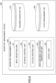
- FIG. 2 is a diagram illustrating an example of the system configuration of the inventory management system according to the first embodiment.
- the inventory management system 100 includes an inventory management device 200, a terminal device 300, and a terminal device 400.
- the inventory management device 200 is connected to the terminal device 300 and the terminal device 400 via a network, such as the Internet or the like.
- the terminal device 300 is a terminal device mainly used in the manufacturer and/or distributor 1
- the terminal device 400 is a terminal device mainly used in the collection center 3.
- the manufacturer of the electrocardiograph 10 is also the distributor thereof, but the manufacturer and the distributor may exist independently.
- the inventory management device 200 includes a required inventory database 210, a state management database 220, and an inventory management unit 230.
- the required inventory database 210 stores required inventory information indicating a required inventory quantity for each medical institution.
- the required inventory database 210 according to the present embodiment may be stored in advance in the inventory management device 200.
- the state management database 220 is provided for each medical institution, and stores state management information including a collection status of the electrocardiograph 10, dispatched from the manufacturer and/or distributor 1 to the medical institution 2, and collected from the patient.
- the state management database 220 according to the present embodiment may be generated by inputting the state management information of the electrocardiograph 10 from the terminal device 300.
- the inventory management unit 230 receives, from the terminal device 300, a notification of dispatch of the electrocardiograph 10 from the manufacturer and/or distributor 1 to the medical institution 2, and updates the state management database 220. In addition, the inventory management unit 230 receives, from the terminal device 400, a notification of collection of the electrocardiograph 10, and updates the state management database 220.
- the inventory management unit 230 computes a used quantity of the electrocardiograph 10, based on the required inventory quantity stored in the required inventory database 210 and the notification from the terminal device 400, generates information indicating an inventory status of the medical institution 2, and transmits the information to the terminal device 300.
- the information indicating the inventory status includes a current inventory quantity (inventory amount) of the electrocardiograph 10 in the medical institution 2, and a replenishment instruction of the electrocardiograph 10 for setting the current inventory quantity to the required inventory quantity.
- the manufacturer and/or distributor 1, who is a user of the terminal device 300 does not need to confirm the used quantity of the electrocardiograph 10 with respect to the medical institution 2, and the load of the inventory management can be reduced.
- the quantity of the electrocardiograph 10 in the present embodiment indicates the number of the electrocardiographs 10.
- one terminal device 300 and one terminal device 400 are included in the inventory management system 100, but the numbers thereof are not limited to one.
- An arbitrary number of terminal devices 300 and an arbitrary number of terminal devices 400 may be included in the inventory management system 100.
- the inventory management device 200 includes the required inventory database 210 and the state management database 220, but the configuration is not limited thereto. A part or all of the required inventory database 210 and the state management database 220 may be provided in an external device other than the inventory management device 200. In this case, the inventory management device 200 and the external device communicate with each other via a network or the like.
- the inventory management device 200 may be configured using a plurality of information processing apparatuses.
- the functions of the inventory management device 200 may be implemented by the plurality of information processing apparatuses.
- FIG. 3 is a diagram illustrating an example of the hardware configuration of the inventory management device according to the first embodiment.
- the inventory management device 200 includes a processor 21, a memory 22, an auxiliary storage device 23, an interface (I/F) device 24, a communication device 25, and a drive device 26. These hardware components of the inventory management device 200 are connected to one another via a bus 27.
- the processor 21 includes various computing devices, such as a central processing unit (CPU), a graphics processing unit (GPU), or the like.
- the processor 21 reads various programs (for example, a learning program or the like) into the memory 22, and executes the programs.
- programs for example, a learning program or the like
- the memory 22 includes a main storage device, such as a read only memory (ROM), a random access memory (RAM), or the like.
- the processor 21 and the memory 22 form a so-called computer, and the inventory management unit 230 is implemented by the computer when the processor 21 executes the various programs read into the memory 22.
- the auxiliary storage device 23 stores various programs, and various types of data used when the various programs are executed by the processor 21.
- the required inventory database 210 and the state management database 220 are implemented in the auxiliary storage device 23.
- the I/F device 24 is a coupling device that connects an operation device 28 and a display device 29, which are examples of external devices, to the inventory management device 200.
- the I/F device 24 receives an operation on the inventory management device 200, via the operation device 28.
- the I/F device 24 may output a result of processing performed by the inventory management device 200, and display the result to a manager of the inventory management device 200, via the display device 29.
- the communication device 25 is a communication device for communicating with other devices (the terminal devices 300 and 400 in the present embodiment).
- the drive device 26 is a device on which a recording medium 30 is set.
- the recording medium 30 includes a medium for optically, electrically, or magnetically recording information, such as a CD-ROM, a flexible disk, a magneto-optical disk, or the like.
- the recording medium 30 may include a semiconductor memory or the like that electrically records information, such as a ROM, a flash memory, or the like.
- the various programs are installed in the auxiliary storage device 23, when a distributed recording medium 30 is set in the drive device 26, and the various programs recorded in the recording medium 30 are read by the drive device 26, for example.
- the various programs are installed in the auxiliary storage device 23 when downloaded from a network via the communication device 25.
- each database of the inventory management device 200 according to the present embodiment will be described with reference to FIG. 4 and FIG. 5 .
- FIG. 4 is a diagram illustrating an example of the required inventory database according to the first embodiment.
- the required inventory database 210 includes a medical institution ID, a medical institution name, a required inventory quantity, or the like, as information items, and the item "medical institution ID" and each of the other items are associated with each another.
- information including a value of the item "medical institution ID" and values of the other items, is the required inventory information.
- the value of the item "medical institution ID” is identification information for identifying the medical institution.
- the value of the item “medical institution name” indicates a name of the medical institution identified by the medical institution ID.
- the value of the item “required inventory quantity” indicates an inventory quantity of the electrocardiograph 10 required in the medical institution identified by the medical institution ID.
- the inventory quantity of the electrocardiograph 10 is set in advance according to a scale of the medical institution, medical departments, or the like, for example. Further, the inventory quantity of the electrocardiograph 10 may be a value that is updated at regular intervals, for example.
- the inventory quantity according to the present embodiment may be stored as a deposit inventory of the medical institution 2, for example.
- the deposit inventory indicates the electrocardiographs 10 owned by the manufacturer and/or distributor 1 but stocked in the medical institution 2.
- the medical institution identified by a medical institution ID "A01" is "hospital A”, and the required inventory quantity is 30.
- FIG. 5 is a diagram illustrating an example of the state management database according to the first embodiment.
- the state management database 220 according to the present embodiment is provided for each medical institution, and FIG. 5 illustrates the state management database 220 of the medical institution identified by the medical institution ID "A01".
- the state management database 220 includes a medical institution ID, a device ID, a status, and an expiration date, as the information items.
- the item “medical institution ID” is associated with the item “device ID”
- the item “device ID” is associated with the item “status”.
- information including a value of the item “medical institution ID”, a value of the item “device ID”, a value of the item “status”, and a value of the item "expiration date” is the state management information.
- the value of the item “device ID” is the identification information for identifying the electrocardiograph 10 dispatched to the medical institution identified by the medical institution ID.
- the value of the item “status” indicates the state of the dispatched electrocardiograph 10. More particularly, the value of the item “status” indicates whether or not the electrocardiograph 10 has been collected at the collection center 3. That is, in the state management database 220, the unique ID of the electrocardiograph 10 is associated with the collection status of the electrocardiograph 10 from the patient.
- the value of the item “expiration date” indicates the expiration date of the electrocardiograph 10 identified by the device ID.
- the electrocardiographs 10 respectively identified by the device ID "101" through the device ID "105” are dispatched to the medical institution identified by the medical institution ID "A01", and none of the electrocardiographs 10 has been collected at the collection center 3.
- the electrocardiographs 10 respectively identified by the device ID "101” through the device ID "105” any one of a state in which the electrocardiographs 10 are either stored in the medical institution at the dispatch destination, or in use by the patients who visited the medical institution at the dispatch destination.
- the expiration dates of the electrocardiographs 10 identified by the device IDs "101" and "102", among the electrocardiographs 10 identified by the device ID "101" through the device ID "105", are March 10, 2021.
- the inventory management device 200 can send a warning notification to the medical institution to prohibit the use of the electrocardiographs 10 having expiration dates that have expired.
- the medical institution at the dispatch destination of the electrocardiograph 10, the device ID of the electrocardiograph 10, and the status indicating the collection status of the electrocardiograph 10, are associated with each other in the state management database 220, but the association is not limited thereto.
- the association may be achieved using a plurality of types of databases.
- the state management database 220 may be implemented by a plurality of databases.
- the state management database 220 may be implemented by a dispatch destination database that stores the medical institution at the dispatch destination of the electrocardiograph 10 and the device ID of the electrocardiograph 10 in association with each other, and a collection status database that stores the device ID of the electrocardiograph 10 and the collection status of the electrocardiograph 10 in association with each other, for example.
- state management information stored in the state management database 220 may include a value indicating the current inventory quantity of the medical institution.
- FIG. 6 is a diagram for explaining the functions of the inventory management device according to the first embodiment.
- the inventory management device 200 includes an inventory management unit 230.
- the inventory management unit 230 includes an input reception unit 231, a storage control unit 232, a status updating unit 233, a replenishment instruction generation unit 234, and an output unit 235.
- the input reception unit 231 receives an input with respect to the inventory management device 200. More particularly, the input reception unit 231 receives an input of the state information from the terminal device 300, and an input of the status of the electrocardiograph 10 or the like from the terminal device 400.
- the storage control unit 232 stores the input received by the input reception unit 231 in the state management database 220.
- the status updating unit 233 updates the value of the item "status" in the state management database 220 according to the input from the terminal device 400.
- the replenishment instruction generation unit 234 refers to the required inventory database 210 and the state management database 220, and generates a replenishment instruction to replenish the inventory for each medical institution. More particularly, the replenishment instruction generation unit 234 refers to the required inventory database 210 and the state management database 220, and computes a replenishment quantity for setting the current inventory quantity of the medical institution to the required inventory quantity.
- the inventory management unit 230 may generate commercial transaction information for issuing a statement of delivery with respect to the medical institution, based on the replenishment instruction to replenish the inventory.
- the replenishment instruction generation unit 234 may function as an inventory status generation unit. More particularly, the replenishment instruction generation unit 234 may generate information indicating the inventory status including both or one of the current inventory quantity of the electrocardiograph 10 and the inventory replenishment instruction based on the required inventory quantity included in the state management information stored in the state management database 220.
- the output unit 235 outputs information to be displayed, with respect to the terminal device 300 and the terminal device 400. More particularly, the output unit 235 outputs the replenishment quantity computed by the replenishment instruction generation unit 234 to the terminal device 300 of the manufacturer and/or distributor 1. In addition, the output unit 235 may issue a statement of delivery based on the commercial transaction information generated according to the inventory replenishment instruction, an invoice in the case of the deposit inventory, or the like, with respect to the medical institution at the inventory replenishment destination, at a timing when the replenishment quantity is output to the terminal device 400.
- the output unit 235 outputs the information indicating the inventory status to the terminal device 300.
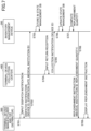
- FIG. 7 is a sequence diagram for explaining the operation of the inventory management system according to the first embodiment.
- the terminal device 300 of the manufacturer and/or distributor 1 displays an input screen for transmitting a dispatch notification of the electrocardiograph 10 to the inventory management device 200 (step S701), and transmits the dispatch notification including the input information to the inventory management device 200 (step S702).
- the dispatch notification includes the device ID and the expiration date of the electrocardiograph 10 to be dispatched, and the medical institution ID of the medical institution at the dispatch destination of the electrocardiograph 10.
- the storage control unit 232 stores the device ID, the expiration date associated with the device ID, and the status in the state management database 220 corresponding to the medical institution ID included in the dispatch notification (step S703). In this state, the status corresponding to the device ID is "uncollected”.
- an input screen for transmitting a collection notification indicating the receipt of the returned electrocardiograph 10 to the inventory management device 200 is displayed on the terminal device 400 (step S704).
- the terminal device 400 transmits the collection notification, including the information input on the input screen, to the inventory management device 200 (step S705). More particularly, the collection notification includes the device ID read from the returned electrocardiograph 10.
- the status updating unit 233 updates the value of the status in the state management database 220 (step S706).
- the status updating unit 233 identifies the state management database 220 of the medical institution including the device ID included in the collection notification, from among the state management databases 220 of the respective medical institutions. Then, the status updating unit 233 updates the status corresponding to the device ID included in the collection notification to "collected" in the identified state management database 220.
- the inventory management device 200 causes the replenishment instruction generation unit 234 to refer to the required inventory database 210, to compute the replenishment quantity of the electrocardiograph 10 with respect to the medical institution, from the required inventory quantity of the medical institution corresponding to the device ID included in the collection notification, and the quantity of collected electrocardiographs 10 (step S707).
- the inventory management device 200 causes the output unit 235 to output the replenishment instruction including the medical institution requiring replenishment of the electrocardiograph 10 and the replenishment quantity of the electrocardiograph 10, with respect to the terminal device 300 of the manufacturer and/or distributor 1 (step S708). More particularly, the replenishment instruction includes the medical institution ID of the medical institution at the replenishment destination of the electrocardiograph 10, and the replenishment quantity of the electrocardiograph 10.
- the terminal device 300 of the manufacturer and/or distributor 1 When the terminal device 300 of the manufacturer and/or distributor 1 receives the replenishment instruction from the inventory management device 200, the terminal device 300 displays the replenishment instruction (step S709).
- the input of the dispatch notification and the display of the replenishment instruction are performed at the terminal device 300, but the input of the dispatch notification and the display of the replenishment instruction are not limited thereto.
- the input of the dispatch notification may be performed by the operation device 28 of the inventory management device 200 and input to the inventory management device 200.
- the replenishment instruction may be displayed on the display device 29 of the inventory management device 200.
- the terminal device 300 according to the present embodiment may display a screen which will be described later, by a web browser or the like, for example. Further, an application distributed for using a service provided by the inventory management system 100 may be installed in the terminal device 300, and the screen which will be described later may be displayed by the application.
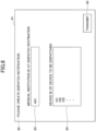
- FIG. 8 is a diagram illustrating an example of an input screen for transmitting the dispatch notification according to the first embodiment.
- a screen 81 illustrated in FIG. 8 is an example of the input screen displayed on the terminal device 300 in step S701 of FIG. 7 , for example.
- the screen 81 includes a display field 82, input fields 83 and 84, and an operation button 85.
- a message prompting creation of a dispatch notification is displayed.
- the medical institution ID of the medical institution at the dispatch destination of the electrocardiograph 10 is input to the input field 83.
- the device ID and the expiration date of each electrocardiograph 10 dispatched to the medical institution identified by the medical institution ID input to the input field 83, are input to the input field 83.
- a dispatch notification including the medical institution ID "A01” and the device IDs "101” through “105", is created and transmitted to the inventory management device 200.
- the device ID is input to the screen 81, but a method of obtaining the device ID is not limited thereto.
- the device ID may be acquired by reading a bar code attached to the electrocardiograph 10 or a packing sheet packing each electrocardiograph 10, for example.
- FIG. 9 is a diagram illustrating a display example of the replenishment instruction according to the first embodiment.
- a screen 91 illustrated in FIG. 9 is an example of the screen displayed on the terminal device 300 in step S709 of FIG. 7 , for example.
- the screen 91 includes display fields 92, 93, and 94.
- the display field 92 displays the name of a medical institution at the replenishment destination (dispatch destination) of the electrocardiograph 10.
- the display field 93 displays the replenishment quantity of the electrocardiograph 10.
- the display field 94 displays the device ID of the electrocardiograph 10 collected from the medical institution displayed in the display field 92.
- the device ID or the like of the electrocardiograph 10 scheduled to be dispatched to the medical institution may be displayed on the screen 91, for example.
- the medical institution uses the electrocardiograph 10 on the patient, and the patient returns the used electrocardiograph 10 to the collection center 3, so that the quantity of the electrocardiographs 10 lacking with respect to the required inventory quantity is automatically replenished from the manufacturer and/or distributor 1.
- the present embodiment there is no need to perform the inventory management of the electrocardiograph 10 in the medical institution, and the load of the inventory management can be reduced.
- the medical institution that used the electrocardiograph 10 and the used quantity of the electrocardiograph 10 can be notified to the manufacturer and/or distributor 1 when the electrocardiograph 10 is collected at the collection center 3.
- the manufacturer and/or distributor 1 does not need to check a use status, the collection status, or the like of the electrocardiograph 10 with respect to the medical institution 2 and the collection center 3, thereby reducing the load of the inventory management.
- the second embodiment differs from the first embodiment in that the device ID, and an analysis result of analysis target data acquired from the electrocardiograph 10 identified by the device ID, are provided to the medical institution 2.
- differences from the first embodiment will be described, and constituent elements having the same functional configurations as those of the first embodiment will be designated by the same reference numerals as the first embodiment, and a description thereof will be omitted.
- the analysis target data according to the present embodiment includes the electrocardiogram waveform data read from the electrocardiograph 10, data obtained by processing the electrocardiogram waveform data to suit input to analysis software, or the like.
- analysis result data that is an analysis result of the analysis target data by the analysis software, includes an analysis result, presence or absence of an error, error information, or the like.
- error information in the present embodiment may include both information on the error of the electrocardiograph 10 itself and an abnormality generated at the time of measurement, for example, and may further include an abnormal value of the electrocardiogram waveform data related to a diagnosis.
- FIG. 10 is a diagram illustrating an example of a system configuration of the inventory management system according to the second embodiment.
- An inventory management system 100A according to the present embodiment includes an inventory management device 200A, and terminal devices 300 and 400. Moreover, in the inventory management system 100A according to the present embodiment, the inventory management device 200A communicates with a terminal device 500.
- the terminal device 500 is mainly used by the medical institution that employs the inventory management system 100A.
- the inventory management device 200A includes a required inventory database 210, a state management database 220A, an analysis result database 240, an inventory management unit 230A, and an analysis result acquisition unit 250.
- the state management database 220A stores state management information indicating the state of the electrocardiograph 10, including the use status of the electrocardiograph 10 by the patient.
- the analysis result database 240 stores analysis result data, that is an analysis result of the analysis target data acquired from the storage device of the electrocardiograph 10 collected at the collection center 3, and activity record information 11 indicating an activity record during measurement of the electrocardiogram waveform data provided from the patient, in association with each other.
- the analysis of the analysis target data may be performed by an analyzer or the like provided externally with respect to the inventory management system 100.
- the analysis result acquisition unit 250 acquires the analysis result data from the external analyzer or the like, and stores the acquired data in the analysis result database 240.
- the analysis result data may include the device ID of the electrocardiograph 10 from which the analysis target data is read.
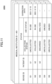
- FIG. 11 is a diagram illustrating an example of the state management database according to the second embodiment.
- the state management database 220A according to the present embodiment includes, as information items, a medical institution ID, a device ID, a status, a patient ID, and a status, and the item “status” includes the items “collection status", "use status", and "expiration date”.
- the value of the item "patient ID” is identification information for identifying the patient, and in the example illustrated in FIG. 11 , indicates the identification information of the patient who uses the electrocardiograph 10 identified by the device ID.
- the value of the item “collection status” included in the item “status” indicates the collection status of the electrocardiograph 10 at the collection center 3.
- the value of the item “use status” indicates the use status of the electrocardiograph 10 by the patient.
- the electrocardiograph 10 identified by the device ID "101” is in a state used by the patient identified by the patient ID "U1", and is not collected at the collection center 3.
- the electrocardiograph 10 identified by the device ID "102" is collected at the collection center 3 after being used by the patient identified by the patient ID "U2", and the electrocardiogram waveform data or the like read from the electrocardiograph 10 is being analyzed.
- the electrocardiograph 10 identified by the device ID "103" is collected at the collection center 3 after being used by the patient identified by the patient ID "U3", and is discarded after the analysis of the electrocardiogram waveform data or the like read from the electrocardiograph 10 is completed.
- the electrocardiographs 10 identified by the device IDs "104" and “105” are unused, and are stored in the medical institution identified by the medical institution ID "A01".
- FIG. 12 is a diagram illustrating an example of the analysis result database according to the second embodiment.
- the analysis result database 240 according to the present embodiment may be provided for each medical institution.
- the analysis result database 240 includes, as information items, a medical institution ID, a device ID, a patient ID, analysis result data, and activity record information, and the item "device ID" and each of the other items are associated with each other.
- analysis result data is analysis result data indicating the analysis result of the analysis target data read from the storage device of the electrocardiograph 10 identified by the device ID.
- the value of the item "behavior record information" is information indicating an activity record of the patient identified by the patient ID during measurement of the electrocardiogram waveform data.
- FIG. 13 is a diagram for explaining the functions of the inventory management device according to the second embodiment.
- the inventory management device 200A includes an inventory management unit 230A, and an analysis result acquisition unit 250.
- the inventory management unit 230A includes an input reception unit 231, a storage control unit 232A, a status updating unit 233A, a replenishment instruction generation unit 234, and an output unit 235.
- the storage control unit 232A stores information input from the terminal device 500 in the state management database 220. In addition, the storage control unit 232A stores the analysis result data acquired from the external analyzer in the analysis result database 240.
- the status updating unit 233A updates the state management database 220A according to information input from the terminal device 500 and the processing performed by the analysis result acquisition unit 250.
- the analysis result acquisition unit 250 acquires the analysis result data of the analysis target data analyzed by the external analyzer.
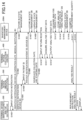
- FIG. 14 is a sequence diagram illustrating the operation of the inventory management system according to the second embodiment.
- step S1401 through step S1403 in FIG. 14 are the same as the processes from step S701 through step S703 in FIG. 7 , a description thereof will be omitted.
- the terminal device 300 transmits a notice of delivery of the electrocardiograph 10 to the terminal device 500 of the medical institution at the dispatch destination of the electrocardiograph 10 (step S1404).
- the delivery notification includes the device ID.
- the delivery notification may include the medical institution ID together with the device ID.
- a person in charge at the medical institution inputs, from the terminal device 500, the patient ID on the input screen for associating the patient ID with the device ID (step S1405) .
- the terminal device 500 transmits a payout notification in which the patient ID and the device ID are associated with each other, to the inventory management device 200A (step S1406).
- the storage control unit 232A identifies the state management database 220A including the device ID included in the payout notification, and stores the patient ID in association with the device ID in the identified state management database 220A (step S1407).
- the inventory management device 200A causes the status updating unit 233A to update the value of the item "collection status" to "uncollected” (refer to FIG. 11 ), and to update the value of the item “use status” to "in use", among the items "status” in the state management database 220A (step S1408).
- the inventory management device 200A notifies a scheduled return date (scheduled collection date) of the electrocardiograph 10 used by the patient, and a date on which the payout notification is received, to the terminal device 500 (step S1409).
- the date on which the payout notification is received is the date (use start date) on which the patient starts to use the delivered electrocardiograph 10.
- both the scheduled collection date and the use start date may be notified to the medical institution, or one of these dates may be notified to the medical institution.
- the use start date may be notified to the medical institution only when the scheduled collection date is not set.
- the scheduled return date may be determined in advance when the patient is to use the electrocardiograph 10. Moreover, when the return notification is not received from the terminal device 400 of the collection center 3 even after the scheduled return date, for example, the inventory management device 200A may output an alarm indicating that the electrocardiograph 10 has not been returned, with respect to the medical institution that paid out the electrocardiograph 10 to the patient. Further, in a case where the scheduled collection date is not set, the inventory management device 200A may output an alarm with respect to the medical institution, using the use start date as a reference.
- the terminal device 400 of the collection center 3 displays an input screen for transmitting the collection notification to the inventory management device 200, and the device ID of the collected electrocardiograph 10 and the patient ID are input to the terminal device 400 (step S1410).
- the electrocardiogram waveform data is read from the storage device of the returned electrocardiograph 10, and the activity record information 11 is provided from the patient.
- the terminal device 400 acquires the analysis target data including such information (step S1411), and outputs the analysis target data to the external analyzer (step S1412).
- the device ID of the electrocardiograph 10 from which the electrocardiogram waveform data is read, and the patient ID of the patient who used the electrocardiograph 10, are included in the analysis target data acquired in step S1410.
- the inventory management device 200A When the inventory management device 200A acquires (receives) the analysis result data from the analyzer to which the terminal device 400 transmitted the analysis target data (step S1413), the inventory management device 200A causes the storage control unit 232A to store the analysis result data in the analysis result database 240 (step S1414). More particularly, the storage control unit 232A stores the device ID included in the analysis result data and the patient ID, the medical institution ID corresponding to the device ID and the patient ID, and the activity record information corresponding to the patient ID, in the analysis result database 240 in association with one another.
- the inventory management device 200A causes the status updating unit 233A to update the state management database 220A (step S1415) .
- the status updating unit 233A updates the value of the item “collection status” to "collected”, and the value of the item “use status” to "analyzed”, among the items "status” in the state management database 220A (refer to FIG. 11 ).
- the inventory management device 200A may receive a discard notification from the terminal device 400, and set the value of the item "collection status" to "discarded".
- the inventory management device 200A causes the replenishment instruction generation unit 234 to refer to the required inventory database 210, and to compute the replenishment quantity of the electrocardiograph 10 with respect to the medical institution, from the required inventory quantity of the medical institution corresponding to the device ID included in the collection notification, and the quantity of the collected electrocardiographs 10 (step S1416) .
- the inventory management device 200A causes the output unit 235 to transmit the analysis result acquired by the analysis result acquisition unit 250 to the terminal device 500 of the medical institution (step S1417).
- the inventory management device 200A causes the output unit 235 to transmit the replenishment instruction and the analysis result to the terminal device 300 (step S1418).
- the terminal device 300 displays the replenishment instruction together with the analysis result (step S1419) .
- the analysis target data is analyzed by the external analyzer, but the analysis is not limited thereto.
- the analyzer may be included in the inventory management system 100A.
- the analyzer that analyzes the analysis target data may be provided in the inventory management device 200A.
- FIG. 15 is a diagram illustrating an example of the input screen for transmitting the payout notification according to the second embodiment.
- a screen 151 illustrated in FIG. 15 is displayed on the terminal device 500 in step S1405 of FIG. 14 , for example.
- the screen 151 includes input fields 152 and 153, and an operation button 154.
- the patient ID of the patient who uses the electrocardiograph 10 is input to the input field 152.
- the device ID of the electrocardiograph 10 to be used is input to the input field 153.
- the terminal device 500 transmits the payout notification to the inventory management device 200A.
- the input information is not limited thereto.
- Information such as gender, age, past medical history, or the like of the patient, may be input on the screen 151, and included in the analysis target information.
- FIG. 16 is a diagram illustrating a display example of the replenishment instruction according to the second embodiment.
- a screen 91A illustrated in FIG. 16 is an example of the screen displayed on the terminal device 300 in step S1417 of FIG. 14 .
- the screen 91A includes display fields 92, 93, 94, and 95.
- the analysis result acquired by the analysis result acquisition unit 250 is displayed in the display field 95.
- the device ID of the electrocardiograph 10 determined to include an error as a result of the analysis is displayed.
- the electrocardiograph 10 is described as an example of the medical device that is a target of inventory management by the inventory management system, however, medical device that is the target of the inventory management by the inventory management system according to the present embodiment is not limited to the electrocardiograph 10.
- the inventory management system described above can be applied to any medical device, as long as the medical device is a single-use medical device that is collected and discarded after being used by the patient.
- Other examples of the single-use medical device that is collected and discarded after being used by the patient include a blood glucose sensor chip for blood glucose monitoring having a measurement result notification function, an electrode material, or the like, for example.
- the present invention is not limited to the configurations of the embodiments described above, and combinations with other elements or the like may be made.
- the present invention may be modified without departing from the scope of the present invention, and can be suitably determined to suit the form of the application.
Landscapes
- Business, Economics & Management (AREA)
- Engineering & Computer Science (AREA)
- Health & Medical Sciences (AREA)
- General Business, Economics & Management (AREA)
- Biomedical Technology (AREA)
- Epidemiology (AREA)
- General Health & Medical Sciences (AREA)
- Medical Informatics (AREA)
- Primary Health Care (AREA)
- Public Health (AREA)
- Economics (AREA)
- Development Economics (AREA)
- Quality & Reliability (AREA)
- Accounting & Taxation (AREA)
- Entrepreneurship & Innovation (AREA)
- Human Resources & Organizations (AREA)
- Marketing (AREA)
- Operations Research (AREA)
- Finance (AREA)
- Strategic Management (AREA)
- Tourism & Hospitality (AREA)
- Physics & Mathematics (AREA)
- General Physics & Mathematics (AREA)
- Theoretical Computer Science (AREA)
- Medical Treatment And Welfare Office Work (AREA)
Abstract
Description
- The present invention relates to inventory management systems, inventory management devices, inventory management methods, and inventory management programs.
- Conventionally, in medical devices, there are demands to individually identify the devices, to clearly record a process from manufacture until disposal through distribution and sale, and to enable checking of history information by following-back from the device.
-
- Patent Document 1:
Japanese Patent No. 6095900 - Patent Document 2:
Japanese Patent No. 6490639 - Patent Document 3:
Japanese Patent No. 678034 - In the manufacture, sales, or the like of the medical devices, it is necessary to hold a distributor's inventory according to each business condition. However, because it is difficult to predict the number, timing, or the like of patients who will visit a medical institution, it is impossible to grasp usage demands of the medical devices, delivery timings of the medical devices, or the like. For this reason, considerable cost and labor are conventionally spent on inventory management.
- According to one aspect, it is an object to reduce a load of inventory management.
- According to one aspect of the present invention, an inventory management system has an inventory management device and a terminal device, and the inventory management device includes an inventory status generation unit configured to generate information indicating an inventory status of a medical device for each of a plurality of medical institutions, by referring to a required inventory storage unit storing information indicating a required inventory quantity of the medical device for each of the plurality of medical institutions, and a state management storage unit storing state management information associating a unique ID of the medical device dispatched to one medical institution with a collection status of the medical device paid out from the one medical institution to a patient for each of the plurality of medical institutions, and an output unit configured to output the information indicating the inventory status to the terminal device.
- The load of inventory management can be reduced.
-
- [
FIG. 1] FIG. 1 is a diagram for explaining an outline of an inventory management system according to a first embodiment. - [
FIG. 2] FIG. 2 is a diagram illustrating an example of a system configuration of the inventory management system according to the first embodiment. - [
FIG. 3] FIG. 3 is a diagram illustrating an example of a hardware configuration of the inventory management device according to the first embodiment. - [
FIG. 4] FIG. 4 is a diagram illustrating an example of a required inventory database according to the first embodiment. - [
FIG. 5] FIG. 5 is a diagram illustrating an example of a state management database according to the first embodiment. - [
FIG. 6] FIG. 6 is a diagram for explaining functions of an inventory management device according to the first embodiment. - [
FIG. 7] FIG. 7 is a sequence diagram for explaining an operation of the inventory management system according to the first embodiment. - [
FIG. 8] FIG. 8 is a diagram illustrating an example of an input screen for transmitting a dispatch notification according to the first embodiment. - [
FIG. 9] FIG. 9 is a diagram illustrating a display example of a replenishment instruction according to the first embodiment. - [
FIG. 10] FIG. 10 is a diagram illustrating an example of a system configuration of the inventory management system according to a second embodiment. - [
FIG. 11] FIG. 11 is a diagram illustrating an example of the state management database according to the second embodiment. - [
FIG. 12] FIG. 12 is a diagram illustrating an example of an analysis result database according to the second embodiment. - [
FIG. 13] FIG. 13 is a diagram for explaining functions of the inventory management device according to the second embodiment. - [
FIG. 14] FIG. 14 is a sequence diagram for explaining the operation of the inventory management system according to the second embodiment. - [
FIG. 15] FIG. 15 is a diagram illustrating an example of the input screen for transmitting a payout notification according to the second embodiment. - [
FIG. 16] FIG. 16 is a diagram illustrating a display example of the replenishment instruction according to the second embodiment. - Hereinafter, a first embodiment will be described with reference to the drawings.
FIG. 1 is a diagram illustrating an outline of an inventory management system according to a first embodiment. - In the following embodiment, an
electrocardiograph 10 will be described as an example of a medical device that is a target of inventory management by aninventory management system 100 according to the present embodiment. - In
FIG. 1 , theelectrocardiograph 10 is manufactured and/or sold by a manufacturer and/ordistributor 1. The manufacturer and/ordistributor 1 refers to a supplier who distributes to medical institutions, and does not indicate a distinction among a manufacturer, a manufacturer and distributor, and a distributor as defined in the Pharmaceutical and Medical Device Act. - The
electrocardiograph 10 according to the present embodiment is a single-use medical device that is collected and discarded after being worn on a body of a patient for a certain period of time. - The
electrocardiograph 10 according to the present embodiment includes a storage device that stores measured electrocardiogram waveform data or the like. In addition, identification information for identifying theelectrocardiograph 10 is stored in the storage device or the like of theelectrocardiograph 10. In the present embodiment, the identification information for uniquely identifying theelectrocardiograph 10 is stored in the storage device of all of theelectrocardiographs 10 manufactured by the manufacturer and/ordistributor 1. - A method of assigning the identification information to the
electrocardiograph 10 is not limited to the method described above. The method of assigning the identification information to theelectrocardiograph 10 may be any method as long as theelectrocardiograph 10 can be associated with the identification information for uniquely identifying theelectrocardiograph 10. In the following description, the identification information (unique ID) for uniquely identifying theelectrocardiograph 10 may also be referred to as a device ID. - In the present embodiment, the
electrocardiograph 10 having the device ID assigned thereto is dispatched from the manufacturer and/ordistributor 1 to a medical institution 2 (procedure S1). - In this state, the
inventory management system 100 according to the present embodiment receives the device ID of thedispatched electrocardiograph 10 and the identification information for uniquely identifying the medical institution that are input from the manufacturer and/ordistributor 1, and holds information associating the device ID and the identification information of the medical institution (procedure S2). In the following description, the identification information for uniquely identifying the medical institution may also be referred to as a medical institution ID. - In the
medical institution 2, theelectrocardiograph 10 is used on a patient P (procedure S3), and the patient P wears theelectrocardiograph 10 to collect the electrocardiogram waveform data from theelectrocardiograph 10. - Then, when the measurement of the electrocardiogram waveform for a certain period of time ends, the patient P returns the
electrocardiograph 10 to acollection center 3 by post or the like (procedure S4). In this state, the patient P provides thecollection center 3 withactivity record information 11 indicating the patient's own activity contents during the period of time in which theelectrocardiograph 10 is worn by the patient P. - The
activity record information 11 is a document or the like, for example, and may be forwarded by post from the patient P to thecollection center 3, together with theelectrocardiograph 10. In addition, theelectrocardiograph 10 may be returned from the patient P who used theelectrocardiograph 10 to themedical institution 2, and may be forwarded by post from themedical institution 2 to thecollection center 3. - The
collection center 3 according to the present embodiment reads the electrocardiogram waveform and the device ID stored in the storage device of the usedelectrocardiograph 10, and thereafter notifies the device ID of theelectrocardiograph 10 to the inventory management system 100 (procedure S5). - Because the device ID of the
electrocardiograph 10 and a medical institution ID of themedical institution 2 are associated with each other and held in theinventory management system 100, theinventory management system 100 detects that an inventory of theelectrocardiograph 10 in themedical institution 2 decreased by one when notified of the device ID. - Then, the
inventory management system 100 instructs the manufacturer and/ordistributor 1 to replenish the inventory of theelectrocardiograph 10 in the medical institution 2 (procedure S6). - A timing at which the
inventory management system 100 instructs the manufacturer and/ordistributor 1 to replenish the inventory may be arbitrarily determined between the manufacturer and/ordistributor 1 and themedical institution 2. More particularly, a replenish instruction to replenish the inventory may be issued in units of a certain period of time, for example. - As described above, in the
inventory management system 100 according to the present embodiment, the device ID for identifying theelectrocardiograph 10 is assigned to the single-use electrocardiograph 10, and the device ID and the medical institution ID for identifying the medical institution to which theelectrocardiograph 10 is dispatched are managed in association with each other. Hence, according to the present embodiment, a user of theinventory management system 100 can grasp a dispatch destination of theelectrocardiograph 10. - Further, when the
electrocardiograph 10 is collected and discarded, theinventory management system 100 according to the present embodiment receives a notification indicating that theelectrocardiograph 10 has been collected together with the device ID of theelectrocardiograph 10, and identifies the medical institution from which theelectrocardiograph 10 was collected. Accordingly, in theinventory management system 100 according to the present embodiment, the user of theinventory management system 100 can grasp usage demands of theelectrocardiograph 10 in the medical institution. - Moreover, the
inventory management system 100 according to the present embodiment can notify a quantity of theelectrocardiograph 10 to be replenished in the medical institution, with respect to the manufacturer and/ordistributor 1, based on the inventory and the usage demands of theelectrocardiograph 10 required in the medical institution. - As described above, according to the present embodiment, neither the manufacturer and/or
distributor 1 nor themedical institution 2 needs to count the inventory and the usage demands of theelectrocardiograph 10, and it is possible to easily manage the inventory and reduce a load of the inventory management. - Hereinafter, a system configuration of the
inventory management system 100 according to the present embodiment will be described with reference toFIG. 2. FIG. 2 is a diagram illustrating an example of the system configuration of the inventory management system according to the first embodiment. - The
inventory management system 100 according to the present embodiment includes aninventory management device 200, aterminal device 300, and aterminal device 400. In theinventory management system 100, theinventory management device 200 is connected to theterminal device 300 and theterminal device 400 via a network, such as the Internet or the like. - In the following description, it is assumed that the
terminal device 300 is a terminal device mainly used in the manufacturer and/ordistributor 1, and that theterminal device 400 is a terminal device mainly used in thecollection center 3. Further, in the following description, it is assumed that the manufacturer of theelectrocardiograph 10 is also the distributor thereof, but the manufacturer and the distributor may exist independently. - The
inventory management device 200 according to the present embodiment includes a requiredinventory database 210, astate management database 220, and aninventory management unit 230. - The required
inventory database 210 stores required inventory information indicating a required inventory quantity for each medical institution. The requiredinventory database 210 according to the present embodiment may be stored in advance in theinventory management device 200. - The
state management database 220 is provided for each medical institution, and stores state management information including a collection status of theelectrocardiograph 10, dispatched from the manufacturer and/ordistributor 1 to themedical institution 2, and collected from the patient. In addition, thestate management database 220 according to the present embodiment may be generated by inputting the state management information of theelectrocardiograph 10 from theterminal device 300. - The
inventory management unit 230 receives, from theterminal device 300, a notification of dispatch of theelectrocardiograph 10 from the manufacturer and/ordistributor 1 to themedical institution 2, and updates thestate management database 220. In addition, theinventory management unit 230 receives, from theterminal device 400, a notification of collection of theelectrocardiograph 10, and updates thestate management database 220. - Further, the
inventory management unit 230 computes a used quantity of theelectrocardiograph 10, based on the required inventory quantity stored in the requiredinventory database 210 and the notification from theterminal device 400, generates information indicating an inventory status of themedical institution 2, and transmits the information to theterminal device 300. The information indicating the inventory status includes a current inventory quantity (inventory amount) of theelectrocardiograph 10 in themedical institution 2, and a replenishment instruction of theelectrocardiograph 10 for setting the current inventory quantity to the required inventory quantity. - Accordingly, the manufacturer and/or
distributor 1, who is a user of theterminal device 300, does not need to confirm the used quantity of theelectrocardiograph 10 with respect to themedical institution 2, and the load of the inventory management can be reduced. The quantity of theelectrocardiograph 10 in the present embodiment indicates the number of theelectrocardiographs 10. - In addition, in the example illustrated in
FIG. 2 , oneterminal device 300 and oneterminal device 400 are included in theinventory management system 100, but the numbers thereof are not limited to one. An arbitrary number ofterminal devices 300 and an arbitrary number ofterminal devices 400 may be included in theinventory management system 100. - Moreover, in the example illustrated in
FIG. 2 , theinventory management device 200 includes the requiredinventory database 210 and thestate management database 220, but the configuration is not limited thereto. A part or all of the requiredinventory database 210 and thestate management database 220 may be provided in an external device other than theinventory management device 200. In this case, theinventory management device 200 and the external device communicate with each other via a network or the like. - Further, the
inventory management device 200 according to the present embodiment may be configured using a plurality of information processing apparatuses. In other words, the functions of theinventory management device 200 may be implemented by the plurality of information processing apparatuses. - Next, a hardware configuration of the
inventory management device 200 according to the present embodiment will be described with reference toFIG. 3. FIG. 3 is a diagram illustrating an example of the hardware configuration of the inventory management device according to the first embodiment. - The
inventory management device 200 according to the present embodiment includes aprocessor 21, amemory 22, anauxiliary storage device 23, an interface (I/F)device 24, acommunication device 25, and adrive device 26. These hardware components of theinventory management device 200 are connected to one another via abus 27. - The
processor 21 includes various computing devices, such as a central processing unit (CPU), a graphics processing unit (GPU), or the like. Theprocessor 21 reads various programs (for example, a learning program or the like) into thememory 22, and executes the programs. - The
memory 22 includes a main storage device, such as a read only memory (ROM), a random access memory (RAM), or the like. Theprocessor 21 and thememory 22 form a so-called computer, and theinventory management unit 230 is implemented by the computer when theprocessor 21 executes the various programs read into thememory 22. - The
auxiliary storage device 23 stores various programs, and various types of data used when the various programs are executed by theprocessor 21. For example, the requiredinventory database 210 and thestate management database 220 are implemented in theauxiliary storage device 23. - The I/
F device 24 is a coupling device that connects anoperation device 28 and adisplay device 29, which are examples of external devices, to theinventory management device 200. The I/F device 24 receives an operation on theinventory management device 200, via theoperation device 28. In addition, the I/F device 24 may output a result of processing performed by theinventory management device 200, and display the result to a manager of theinventory management device 200, via thedisplay device 29. - The
communication device 25 is a communication device for communicating with other devices (theterminal devices - The
drive device 26 is a device on which arecording medium 30 is set. Therecording medium 30 includes a medium for optically, electrically, or magnetically recording information, such as a CD-ROM, a flexible disk, a magneto-optical disk, or the like. Moreover, therecording medium 30 may include a semiconductor memory or the like that electrically records information, such as a ROM, a flash memory, or the like. - The various programs are installed in the
auxiliary storage device 23, when a distributedrecording medium 30 is set in thedrive device 26, and the various programs recorded in therecording medium 30 are read by thedrive device 26, for example. Alternatively, the various programs are installed in theauxiliary storage device 23 when downloaded from a network via thecommunication device 25. - Next, each database of the
inventory management device 200 according to the present embodiment will be described with reference toFIG. 4 and FIG. 5 . -
FIG. 4 is a diagram illustrating an example of the required inventory database according to the first embodiment. The requiredinventory database 210 according to the present embodiment includes a medical institution ID, a medical institution name, a required inventory quantity, or the like, as information items, and the item "medical institution ID" and each of the other items are associated with each another. In the present embodiment, information including a value of the item "medical institution ID" and values of the other items, is the required inventory information. - The value of the item "medical institution ID" is identification information for identifying the medical institution. The value of the item "medical institution name" indicates a name of the medical institution identified by the medical institution ID. The value of the item "required inventory quantity" indicates an inventory quantity of the
electrocardiograph 10 required in the medical institution identified by the medical institution ID. The inventory quantity of theelectrocardiograph 10 is set in advance according to a scale of the medical institution, medical departments, or the like, for example. Further, the inventory quantity of theelectrocardiograph 10 may be a value that is updated at regular intervals, for example. - In addition, the inventory quantity according to the present embodiment may be stored as a deposit inventory of the
medical institution 2, for example. The deposit inventory indicates theelectrocardiographs 10 owned by the manufacturer and/ordistributor 1 but stocked in themedical institution 2. - In the example illustrated in
FIG. 4 , the medical institution identified by a medical institution ID "A01" is "hospital A", and the required inventory quantity is 30. -
FIG. 5 is a diagram illustrating an example of the state management database according to the first embodiment. Thestate management database 220 according to the present embodiment is provided for each medical institution, andFIG. 5 illustrates thestate management database 220 of the medical institution identified by the medical institution ID "A01". - The
state management database 220 according to the present embodiment includes a medical institution ID, a device ID, a status, and an expiration date, as the information items. The item "medical institution ID" is associated with the item "device ID", and the item "device ID" is associated with the item "status". In the present embodiment, information including a value of the item "medical institution ID", a value of the item "device ID", a value of the item "status", and a value of the item "expiration date", is the state management information. - The value of the item "device ID" is the identification information for identifying the
electrocardiograph 10 dispatched to the medical institution identified by the medical institution ID. The value of the item "status" indicates the state of the dispatchedelectrocardiograph 10. More particularly, the value of the item "status" indicates whether or not theelectrocardiograph 10 has been collected at thecollection center 3. That is, in thestate management database 220, the unique ID of theelectrocardiograph 10 is associated with the collection status of theelectrocardiograph 10 from the patient. The value of the item "expiration date" indicates the expiration date of theelectrocardiograph 10 identified by the device ID. - In the example illustrated in
FIG. 5 , it may be seen that theelectrocardiographs 10 respectively identified by the device ID "101" through the device ID "105" are dispatched to the medical institution identified by the medical institution ID "A01", and none of theelectrocardiographs 10 has been collected at thecollection center 3. In other words, theelectrocardiographs 10 respectively identified by the device ID "101" through the device ID "105" any one of a state in which theelectrocardiographs 10 are either stored in the medical institution at the dispatch destination, or in use by the patients who visited the medical institution at the dispatch destination. - In addition, it may be seen that the expiration dates of the
electrocardiographs 10 identified by the device IDs "101" and "102", among theelectrocardiographs 10 identified by the device ID "101" through the device ID "105", are March 10, 2021. - In the present embodiment, because the device ID and the expiration date are associated with each other as described above, the
inventory management device 200 can send a warning notification to the medical institution to prohibit the use of theelectrocardiographs 10 having expiration dates that have expired. - In the present embodiment, the medical institution at the dispatch destination of the
electrocardiograph 10, the device ID of theelectrocardiograph 10, and the status indicating the collection status of theelectrocardiograph 10, are associated with each other in thestate management database 220, but the association is not limited thereto. The association may be achieved using a plurality of types of databases. In other words, thestate management database 220 may be implemented by a plurality of databases. - More particularly, the
state management database 220 may be implemented by a dispatch destination database that stores the medical institution at the dispatch destination of theelectrocardiograph 10 and the device ID of theelectrocardiograph 10 in association with each other, and a collection status database that stores the device ID of theelectrocardiograph 10 and the collection status of theelectrocardiograph 10 in association with each other, for example. - In addition, the state management information stored in the
state management database 220 may include a value indicating the current inventory quantity of the medical institution. - Next, the functions of the
inventory management device 200 according to the present embodiment will be described.FIG. 6 is a diagram for explaining the functions of the inventory management device according to the first embodiment. - The
inventory management device 200 according to the present embodiment includes aninventory management unit 230. Theinventory management unit 230 includes aninput reception unit 231, astorage control unit 232, astatus updating unit 233, a replenishmentinstruction generation unit 234, and anoutput unit 235. - The
input reception unit 231 receives an input with respect to theinventory management device 200. More particularly, theinput reception unit 231 receives an input of the state information from theterminal device 300, and an input of the status of theelectrocardiograph 10 or the like from theterminal device 400. - The
storage control unit 232 stores the input received by theinput reception unit 231 in thestate management database 220. - The
status updating unit 233 updates the value of the item "status" in thestate management database 220 according to the input from theterminal device 400. - The replenishment
instruction generation unit 234 refers to the requiredinventory database 210 and thestate management database 220, and generates a replenishment instruction to replenish the inventory for each medical institution. More particularly, the replenishmentinstruction generation unit 234 refers to the requiredinventory database 210 and thestate management database 220, and computes a replenishment quantity for setting the current inventory quantity of the medical institution to the required inventory quantity. - When the replenishment
instruction generation unit 234 generates the replenishment instruction to replenish the inventory, theinventory management unit 230 may generate commercial transaction information for issuing a statement of delivery with respect to the medical institution, based on the replenishment instruction to replenish the inventory. - In addition, the replenishment
instruction generation unit 234 according to the present embodiment may function as an inventory status generation unit. More particularly, the replenishmentinstruction generation unit 234 may generate information indicating the inventory status including both or one of the current inventory quantity of theelectrocardiograph 10 and the inventory replenishment instruction based on the required inventory quantity included in the state management information stored in thestate management database 220. - The
output unit 235 outputs information to be displayed, with respect to theterminal device 300 and theterminal device 400. More particularly, theoutput unit 235 outputs the replenishment quantity computed by the replenishmentinstruction generation unit 234 to theterminal device 300 of the manufacturer and/ordistributor 1. In addition, theoutput unit 235 may issue a statement of delivery based on the commercial transaction information generated according to the inventory replenishment instruction, an invoice in the case of the deposit inventory, or the like, with respect to the medical institution at the inventory replenishment destination, at a timing when the replenishment quantity is output to theterminal device 400. - Moreover, in the case where the replenishment
instruction generation unit 234 generates the information indicating the inventory status including the replenishment instruction, theoutput unit 235 outputs the information indicating the inventory status to theterminal device 300. - Next, an operation of the
inventory management system 100 according to the present embodiment will be described with reference toFIG. 7. FIG. 7 is a sequence diagram for explaining the operation of the inventory management system according to the first embodiment. - In the
inventory management system 100 according to the present embodiment, theterminal device 300 of the manufacturer and/ordistributor 1 displays an input screen for transmitting a dispatch notification of theelectrocardiograph 10 to the inventory management device 200 (step S701), and transmits the dispatch notification including the input information to the inventory management device 200 (step S702). - More particularly, the dispatch notification includes the device ID and the expiration date of the
electrocardiograph 10 to be dispatched, and the medical institution ID of the medical institution at the dispatch destination of theelectrocardiograph 10. - When the
input reception unit 231 of theinventory management device 200 receives the dispatch notification, thestorage control unit 232 stores the device ID, the expiration date associated with the device ID, and the status in thestate management database 220 corresponding to the medical institution ID included in the dispatch notification (step S703). In this state, the status corresponding to the device ID is "uncollected". - Next, in the
inventory management system 100, when thecollection center 3 receives the return of theelectrocardiograph 10 from a patient P, an input screen for transmitting a collection notification indicating the receipt of the returnedelectrocardiograph 10 to theinventory management device 200 is displayed on the terminal device 400 (step S704). - Then, the
terminal device 400 transmits the collection notification, including the information input on the input screen, to the inventory management device 200 (step S705). More particularly, the collection notification includes the device ID read from the returnedelectrocardiograph 10. - When the
inventory management device 200 receives the collection notification from theterminal device 400, thestatus updating unit 233 updates the value of the status in the state management database 220 (step S706). - More particularly, the
status updating unit 233 identifies thestate management database 220 of the medical institution including the device ID included in the collection notification, from among thestate management databases 220 of the respective medical institutions. Then, thestatus updating unit 233 updates the status corresponding to the device ID included in the collection notification to "collected" in the identifiedstate management database 220. - Next, the
inventory management device 200 causes the replenishmentinstruction generation unit 234 to refer to the requiredinventory database 210, to compute the replenishment quantity of theelectrocardiograph 10 with respect to the medical institution, from the required inventory quantity of the medical institution corresponding to the device ID included in the collection notification, and the quantity of collected electrocardiographs 10 (step S707). - Next, the
inventory management device 200 causes theoutput unit 235 to output the replenishment instruction including the medical institution requiring replenishment of theelectrocardiograph 10 and the replenishment quantity of theelectrocardiograph 10, with respect to theterminal device 300 of the manufacturer and/or distributor 1 (step S708). More particularly, the replenishment instruction includes the medical institution ID of the medical institution at the replenishment destination of theelectrocardiograph 10, and the replenishment quantity of theelectrocardiograph 10. - When the
terminal device 300 of the manufacturer and/ordistributor 1 receives the replenishment instruction from theinventory management device 200, theterminal device 300 displays the replenishment instruction (step S709). - In the example illustrated in
FIG. 7 , the input of the dispatch notification and the display of the replenishment instruction are performed at theterminal device 300, but the input of the dispatch notification and the display of the replenishment instruction are not limited thereto. The input of the dispatch notification may be performed by theoperation device 28 of theinventory management device 200 and input to theinventory management device 200. In addition, the replenishment instruction may be displayed on thedisplay device 29 of theinventory management device 200. - Hereinafter, display examples of the
terminal device 300 according to the present embodiment will be described with reference toFIG. 8 andFIG. 9 . Theterminal device 300 according to the present embodiment may display a screen which will be described later, by a web browser or the like, for example. Further, an application distributed for using a service provided by theinventory management system 100 may be installed in theterminal device 300, and the screen which will be described later may be displayed by the application. -
FIG. 8 is a diagram illustrating an example of an input screen for transmitting the dispatch notification according to the first embodiment. Ascreen 81 illustrated inFIG. 8 is an example of the input screen displayed on theterminal device 300 in step S701 ofFIG. 7 , for example. - The
screen 81 includes adisplay field 82, input fields 83 and 84, and anoperation button 85. In thedisplay field 82, a message prompting creation of a dispatch notification is displayed. - The medical institution ID of the medical institution at the dispatch destination of the
electrocardiograph 10 is input to theinput field 83. The device ID and the expiration date of eachelectrocardiograph 10 dispatched to the medical institution identified by the medical institution ID input to theinput field 83, are input to theinput field 83. - In the example illustrated in
FIG. 8 , it may be seen that theelectrocardiographs 10 identified by the device IDs "101" through "105" are dispatched to the medical institution identified by the medical institution ID "A01". - When the
operation button 85 is manipulated after the medical institution ID and the device ID are input to the input fields 83 and 84 on thescreen 81, a dispatch notification, including the medical institution ID "A01" and the device IDs "101" through "105", is created and transmitted to theinventory management device 200. - In the present embodiment, the device ID is input to the
screen 81, but a method of obtaining the device ID is not limited thereto. The device ID may be acquired by reading a bar code attached to theelectrocardiograph 10 or a packing sheet packing eachelectrocardiograph 10, for example. -
FIG. 9 is a diagram illustrating a display example of the replenishment instruction according to the first embodiment. Ascreen 91 illustrated inFIG. 9 is an example of the screen displayed on theterminal device 300 in step S709 ofFIG. 7 , for example. - The
screen 91 includes display fields 92, 93, and 94. Thedisplay field 92 displays the name of a medical institution at the replenishment destination (dispatch destination) of theelectrocardiograph 10. Thedisplay field 93 displays the replenishment quantity of theelectrocardiograph 10. Thedisplay field 94 displays the device ID of theelectrocardiograph 10 collected from the medical institution displayed in thedisplay field 92. - In the present embodiment, the device ID or the like of the
electrocardiograph 10 scheduled to be dispatched to the medical institution may be displayed on thescreen 91, for example. - As described above, according to the present embodiment, the medical institution uses the
electrocardiograph 10 on the patient, and the patient returns the usedelectrocardiograph 10 to thecollection center 3, so that the quantity of theelectrocardiographs 10 lacking with respect to the required inventory quantity is automatically replenished from the manufacturer and/ordistributor 1. Hence, according to the present embodiment, there is no need to perform the inventory management of theelectrocardiograph 10 in the medical institution, and the load of the inventory management can be reduced. - Further, in the present embodiment, by associating the device ID of the
electrocardiograph 10 with the medical institution ID at the dispatch destination when dispatching theelectrocardiograph 10, the medical institution that used theelectrocardiograph 10 and the used quantity of theelectrocardiograph 10 can be notified to the manufacturer and/ordistributor 1 when theelectrocardiograph 10 is collected at thecollection center 3. Thus, the manufacturer and/ordistributor 1 does not need to check a use status, the collection status, or the like of theelectrocardiograph 10 with respect to themedical institution 2 and thecollection center 3, thereby reducing the load of the inventory management. - Hereinafter, a second embodiment will be described with reference to the drawings. The second embodiment differs from the first embodiment in that the device ID, and an analysis result of analysis target data acquired from the
electrocardiograph 10 identified by the device ID, are provided to themedical institution 2. In the following description of the second embodiment, differences from the first embodiment will be described, and constituent elements having the same functional configurations as those of the first embodiment will be designated by the same reference numerals as the first embodiment, and a description thereof will be omitted. - The analysis target data according to the present embodiment includes the electrocardiogram waveform data read from the
electrocardiograph 10, data obtained by processing the electrocardiogram waveform data to suit input to analysis software, or the like. - In addition, analysis result data, that is an analysis result of the analysis target data by the analysis software, includes an analysis result, presence or absence of an error, error information, or the like. The error information in the present embodiment may include both information on the error of the
electrocardiograph 10 itself and an abnormality generated at the time of measurement, for example, and may further include an abnormal value of the electrocardiogram waveform data related to a diagnosis. -
FIG. 10 is a diagram illustrating an example of a system configuration of the inventory management system according to the second embodiment. Aninventory management system 100A according to the present embodiment includes aninventory management device 200A, andterminal devices inventory management system 100A according to the present embodiment, theinventory management device 200A communicates with aterminal device 500. Theterminal device 500 is mainly used by the medical institution that employs theinventory management system 100A. - The
inventory management device 200A according to the present embodiment includes a requiredinventory database 210, astate management database 220A, ananalysis result database 240, aninventory management unit 230A, and an analysisresult acquisition unit 250. - The
state management database 220A stores state management information indicating the state of theelectrocardiograph 10, including the use status of theelectrocardiograph 10 by the patient. - The
analysis result database 240 stores analysis result data, that is an analysis result of the analysis target data acquired from the storage device of theelectrocardiograph 10 collected at thecollection center 3, andactivity record information 11 indicating an activity record during measurement of the electrocardiogram waveform data provided from the patient, in association with each other. - In the present embodiment, the analysis of the analysis target data may be performed by an analyzer or the like provided externally with respect to the
inventory management system 100. - The analysis result
acquisition unit 250 acquires the analysis result data from the external analyzer or the like, and stores the acquired data in theanalysis result database 240. In this state, the analysis result data may include the device ID of theelectrocardiograph 10 from which the analysis target data is read. - Hereinafter, the
state management database 220A and theanalysis result database 240 according to the present embodiment will be described with reference toFIG. 11 andFIG. 12 . -
FIG. 11 is a diagram illustrating an example of the state management database according to the second embodiment. Thestate management database 220A according to the present embodiment includes, as information items, a medical institution ID, a device ID, a status, a patient ID, and a status, and the item "status" includes the items "collection status", "use status", and "expiration date". - The value of the item "patient ID" is identification information for identifying the patient, and in the example illustrated in
FIG. 11 , indicates the identification information of the patient who uses theelectrocardiograph 10 identified by the device ID. - The value of the item "collection status" included in the item "status" indicates the collection status of the
electrocardiograph 10 at thecollection center 3. The value of the item "use status" indicates the use status of theelectrocardiograph 10 by the patient. - In the example illustrated in
FIG. 11 , theelectrocardiograph 10 identified by the device ID "101" is in a state used by the patient identified by the patient ID "U1", and is not collected at thecollection center 3. - In addition, the
electrocardiograph 10 identified by the device ID "102" is collected at thecollection center 3 after being used by the patient identified by the patient ID "U2", and the electrocardiogram waveform data or the like read from theelectrocardiograph 10 is being analyzed. - Moreover, the
electrocardiograph 10 identified by the device ID "103" is collected at thecollection center 3 after being used by the patient identified by the patient ID "U3", and is discarded after the analysis of the electrocardiogram waveform data or the like read from theelectrocardiograph 10 is completed. - Further, it may be seen that the
electrocardiographs 10 identified by the device IDs "104" and "105" are unused, and are stored in the medical institution identified by the medical institution ID "A01". -
FIG. 12 is a diagram illustrating an example of the analysis result database according to the second embodiment. Theanalysis result database 240 according to the present embodiment may be provided for each medical institution. Theanalysis result database 240 includes, as information items, a medical institution ID, a device ID, a patient ID, analysis result data, and activity record information, and the item "device ID" and each of the other items are associated with each other. - The value of the item "analysis result data" is analysis result data indicating the analysis result of the analysis target data read from the storage device of the
electrocardiograph 10 identified by the device ID. - The value of the item "behavior record information" is information indicating an activity record of the patient identified by the patient ID during measurement of the electrocardiogram waveform data.
- Next, functions of the
inventory management device 200A according to the present embodiment will be described with reference toFIG. 13. FIG. 13 is a diagram for explaining the functions of the inventory management device according to the second embodiment. - The
inventory management device 200A according to the present embodiment includes aninventory management unit 230A, and an analysisresult acquisition unit 250. Theinventory management unit 230A includes aninput reception unit 231, astorage control unit 232A, astatus updating unit 233A, a replenishmentinstruction generation unit 234, and anoutput unit 235. - The
storage control unit 232A stores information input from theterminal device 500 in thestate management database 220. In addition, thestorage control unit 232A stores the analysis result data acquired from the external analyzer in theanalysis result database 240. - The
status updating unit 233A updates thestate management database 220A according to information input from theterminal device 500 and the processing performed by the analysisresult acquisition unit 250. - The analysis result
acquisition unit 250 acquires the analysis result data of the analysis target data analyzed by the external analyzer. - Next, ab operation of the
inventory management system 100A according to the present embodiment will be described with reference toFIG. 14. FIG. 14 is a sequence diagram illustrating the operation of the inventory management system according to the second embodiment. - Because processes of step S1401 through step S1403 in
FIG. 14 are the same as the processes from step S701 through step S703 inFIG. 7 , a description thereof will be omitted. - Next, the
terminal device 300 transmits a notice of delivery of theelectrocardiograph 10 to theterminal device 500 of the medical institution at the dispatch destination of the electrocardiograph 10 (step S1404). The delivery notification includes the device ID. The delivery notification may include the medical institution ID together with the device ID. - When the patient uses the
electrocardiograph 10 delivered to the medical institution, a person in charge at the medical institution inputs, from theterminal device 500, the patient ID on the input screen for associating the patient ID with the device ID (step S1405) . - Next, the
terminal device 500 transmits a payout notification in which the patient ID and the device ID are associated with each other, to theinventory management device 200A (step S1406). - When the
inventory management device 200A receives the payout notification, thestorage control unit 232A identifies thestate management database 220A including the device ID included in the payout notification, and stores the patient ID in association with the device ID in the identifiedstate management database 220A (step S1407). - Next, the
inventory management device 200A causes thestatus updating unit 233A to update the value of the item "collection status" to "uncollected" (refer toFIG. 11 ), and to update the value of the item "use status" to "in use", among the items "status" in thestate management database 220A (step S1408). - Next, the
inventory management device 200A notifies a scheduled return date (scheduled collection date) of theelectrocardiograph 10 used by the patient, and a date on which the payout notification is received, to the terminal device 500 (step S1409). In other words, the date on which the payout notification is received is the date (use start date) on which the patient starts to use the deliveredelectrocardiograph 10. In the present embodiment, both the scheduled collection date and the use start date may be notified to the medical institution, or one of these dates may be notified to the medical institution. In addition, in the present embodiment, the use start date may be notified to the medical institution only when the scheduled collection date is not set. - The scheduled return date may be determined in advance when the patient is to use the
electrocardiograph 10. Moreover, when the return notification is not received from theterminal device 400 of thecollection center 3 even after the scheduled return date, for example, theinventory management device 200A may output an alarm indicating that theelectrocardiograph 10 has not been returned, with respect to the medical institution that paid out theelectrocardiograph 10 to the patient. Further, in a case where the scheduled collection date is not set, theinventory management device 200A may output an alarm with respect to the medical institution, using the use start date as a reference. - Next, when the
electrocardiograph 10 returned from the patient identified by the patient ID is received, theterminal device 400 of thecollection center 3 displays an input screen for transmitting the collection notification to theinventory management device 200, and the device ID of the collectedelectrocardiograph 10 and the patient ID are input to the terminal device 400 (step S1410). - Next, in the
collection center 3, the electrocardiogram waveform data is read from the storage device of the returnedelectrocardiograph 10, and theactivity record information 11 is provided from the patient. Theterminal device 400 acquires the analysis target data including such information (step S1411), and outputs the analysis target data to the external analyzer (step S1412). The device ID of theelectrocardiograph 10 from which the electrocardiogram waveform data is read, and the patient ID of the patient who used theelectrocardiograph 10, are included in the analysis target data acquired in step S1410. - When the
inventory management device 200A acquires (receives) the analysis result data from the analyzer to which theterminal device 400 transmitted the analysis target data (step S1413), theinventory management device 200A causes thestorage control unit 232A to store the analysis result data in the analysis result database 240 (step S1414). More particularly, thestorage control unit 232A stores the device ID included in the analysis result data and the patient ID, the medical institution ID corresponding to the device ID and the patient ID, and the activity record information corresponding to the patient ID, in theanalysis result database 240 in association with one another. - Next, the
inventory management device 200A causes thestatus updating unit 233A to update thestate management database 220A (step S1415) . - More particularly, the
status updating unit 233A updates the value of the item "collection status" to "collected", and the value of the item "use status" to "analyzed", among the items "status" in thestate management database 220A (refer toFIG. 11 ). - In a case where the
electrocardiograph 10 is discarded after the analysis of the analysis target data, theinventory management device 200A may receive a discard notification from theterminal device 400, and set the value of the item "collection status" to "discarded". - Next, the
inventory management device 200A causes the replenishmentinstruction generation unit 234 to refer to the requiredinventory database 210, and to compute the replenishment quantity of theelectrocardiograph 10 with respect to the medical institution, from the required inventory quantity of the medical institution corresponding to the device ID included in the collection notification, and the quantity of the collected electrocardiographs 10 (step S1416) . - Next, the
inventory management device 200A causes theoutput unit 235 to transmit the analysis result acquired by the analysisresult acquisition unit 250 to theterminal device 500 of the medical institution (step S1417). - In addition, the
inventory management device 200A causes theoutput unit 235 to transmit the replenishment instruction and the analysis result to the terminal device 300 (step S1418). - When the replenishment instruction is received, the
terminal device 300 displays the replenishment instruction together with the analysis result (step S1419) . - In the present embodiment, the analysis target data is analyzed by the external analyzer, but the analysis is not limited thereto. The analyzer may be included in the
inventory management system 100A. Moreover, the analyzer that analyzes the analysis target data may be provided in theinventory management device 200A. - Hereinafter, a display example according to the present embodiment will be described with reference to
FIG. 15 andFIG. 16 .FIG. 15 is a diagram illustrating an example of the input screen for transmitting the payout notification according to the second embodiment. - A
screen 151 illustrated inFIG. 15 is displayed on theterminal device 500 in step S1405 ofFIG. 14 , for example. - The
screen 151 includes input fields 152 and 153, and anoperation button 154. The patient ID of the patient who uses theelectrocardiograph 10 is input to theinput field 152. The device ID of theelectrocardiograph 10 to be used is input to theinput field 153. - When the
operation button 154 is manipulated after the inputs with respect to the input fields 152 and 153 are made, theterminal device 500 transmits the payout notification to theinventory management device 200A. - In the
screen 151, only the patient ID is input as the information for identifying the patient, but the input information is not limited thereto. Information, such as gender, age, past medical history, or the like of the patient, may be input on thescreen 151, and included in the analysis target information. -
FIG. 16 is a diagram illustrating a display example of the replenishment instruction according to the second embodiment. Ascreen 91A illustrated inFIG. 16 is an example of the screen displayed on theterminal device 300 in step S1417 ofFIG. 14 . - The
screen 91A includes display fields 92, 93, 94, and 95. The analysis result acquired by the analysisresult acquisition unit 250 is displayed in thedisplay field 95. In the example illustrated inFIG. 16 , the device ID of theelectrocardiograph 10 determined to include an error as a result of the analysis, is displayed. - In the present embodiment, by notifying the analysis result of the electrocardiogram waveform data acquired from the
electrocardiograph 10 to a person in charge at the manufacturer and/ordistributor 1 as described above, it is possible to prompt the medical institution to replenish the patient who uses theelectrocardiograph 10 in which the error occurred, with anew electrocardiograph 10, for example. - Further, in the present embodiment, it is possible to track a distribution path from the dispatch to the return of the
electrocardiograph 10 in which the error occurred. - In the embodiment described above, the
electrocardiograph 10 is described as an example of the medical device that is a target of inventory management by the inventory management system, however, medical device that is the target of the inventory management by the inventory management system according to the present embodiment is not limited to theelectrocardiograph 10. - The inventory management system described above can be applied to any medical device, as long as the medical device is a single-use medical device that is collected and discarded after being used by the patient. Other examples of the single-use medical device that is collected and discarded after being used by the patient include a blood glucose sensor chip for blood glucose monitoring having a measurement result notification function, an electrode material, or the like, for example.
- The present invention is not limited to the configurations of the embodiments described above, and combinations with other elements or the like may be made. The present invention may be modified without departing from the scope of the present invention, and can be suitably determined to suit the form of the application.
- Further, the present international application is based on and claims priority to
Japanese Patent Application No. 2021-043822, filed on March 17, 2021 -
- 100, 100A
- inventory management system
- 200, 200A
- inventory management device
- 210
- required inventory database
- 220, 220A
- state management database
- 230
- inventory management unit
- 231
- input reception unit
- 232
- storage control unit
- 233
- status updating unit
- 234
- replenishment instruction generation unit
- 235
- output unit
- 240
- analysis result database
- 250
- analysis result acquisition unit
- 300, 400, 500
- terminal device
Claims (11)
- An inventory management system comprising an inventory management device and a terminal device, wherein the inventory management device includes:an inventory status generation unit configured to generate information indicating an inventory status of a medical device for each of a plurality of medical institutions, by referring to a required inventory storage unit storing information indicating a required inventory quantity of the medical device for each of the plurality of medical institutions, and a state management storage unit storing state management information associating a unique ID of the medical device dispatched to one medical institution with a collection status of the medical device paid out from the one medical institution to a patient for each of the plurality of medical institutions; andan output unit configured to output the information indicating the inventory status to the terminal device.
- The inventory management system as claimed in claim 1, wherein the information indicating the inventory status includes a current inventory quantity of the medical device and/or a replenishment instruction to replenish the inventory of the medical device.
- The inventory management system as claimed in claim 2, comprising:a storage control unit configured to receive an input of a patient ID for identifying the patient wearing the medical device and store the patient ID in the state management storage unit in association with the unique ID of the medical device,wherein the output unit outputs a scheduled collection date of the medical device from the patient wearing the medical device and/or a use starting date of the medical device by the patient, to the terminal device.
- The inventory management system as claimed in claim 2 or 3, comprising:an analysis result acquisition unit configured to acquire analysis result data indicating an analysis result of analysis target data measured by the medical device dispatched to the one medical institution for each of the plurality of medical institutions,wherein the output unit outputs the analysis result data acquired by the analysis result acquisition unit to the terminal device together with the replenishment instruction.
- The inventory management system as claimed in claim 4, wherein the analysis result data includes information related to an error of the medical device.
- The inventory management system as claimed in any one of claims 1 to 5, wherein the medical device is a single-use medical device.
- The inventory management system as claimed in any one of claims 1 to 6, wherein the medical device is an electrocardiograph.
- The inventory management system as claimed in claim 7, wherein the analysis target data measured by the medical device includes electrocardiogram waveform data measured by the electrocardiograph.
- An inventory management device comprising:an inventory status generation unit configured to generate information indicating an inventory status of a medical device for each of a plurality of medical institutions, by referring to a required inventory storage unit storing information indicating a required inventory quantity of the medical device for each of the plurality of medical institutions, and a state management storage unit storing state management information associating a unique ID of the medical device dispatched to one medical institution with a collection status of the medical device paid out from the one medical institution to a patient for each of the plurality of medical institutions; andan output unit configured to output the information indicating the inventory status.
- An inventory management method implemented by an inventory management system including an inventory management device and a terminal device, the inventory management method comprising:generating, by the inventory management device, information indicating an inventory status of a medical device for each of a plurality of medical institutions, by referring to a required inventory storage unit storing information indicating a required inventory quantity of the medical device for each of the plurality of medical institutions, and a state management storage unit storing state management information associating a unique ID of the medical device dispatched to one medical institution with a collection status of the medical device paid out from the one medical institution to a patient for each of the plurality of medical institutions; andoutputting, by the inventory management device, the information indicating the inventory status to the terminal device.
- An inventory management program for causing a computer to perform a process comprising:generating information indicating an inventory status of a medical device for each of a plurality of medical institutions, by referring to a required inventory storage unit storing information indicating a required inventory quantity of the medical device for each of the plurality of medical institutions, and a state management storage unit storing state management information associating a unique ID of the medical device dispatched to one medical institution with a collection status of the medical device paid out from the one medical institution to a patient for each of the plurality of medical institutions; andoutputting the information indicating the inventory status.
Applications Claiming Priority (2)
| Application Number | Priority Date | Filing Date | Title |
|---|---|---|---|
| JP2021043822 | 2021-03-17 | ||
| PCT/JP2022/011066 WO2022196581A1 (en) | 2021-03-17 | 2022-03-11 | Inventory management system, inventory management device, inventory management method, and inventory management program |
Publications (2)
| Publication Number | Publication Date |
|---|---|
| EP4310857A1 true EP4310857A1 (en) | 2024-01-24 |
| EP4310857A4 EP4310857A4 (en) | 2025-02-26 |
Family
ID=83320676
Family Applications (1)
| Application Number | Title | Priority Date | Filing Date |
|---|---|---|---|
| EP22771329.4A Pending EP4310857A4 (en) | 2021-03-17 | 2022-03-11 | INVENTORY MANAGEMENT SYSTEM, INVENTORY MANAGEMENT DEVICE, INVENTORY MANAGEMENT METHOD, AND INVENTORY MANAGEMENT PROGRAM |
Country Status (5)
| Country | Link |
|---|---|
| US (1) | US20240144176A1 (en) |
| EP (1) | EP4310857A4 (en) |
| JP (1) | JPWO2022196581A1 (en) |
| CN (1) | CN116982116A (en) |
| WO (1) | WO2022196581A1 (en) |
Families Citing this family (1)
| Publication number | Priority date | Publication date | Assignee | Title |
|---|---|---|---|---|
| WO2024166795A1 (en) * | 2023-02-09 | 2024-08-15 | 日東電工株式会社 | Management system and management method |
Family Cites Families (19)
| Publication number | Priority date | Publication date | Assignee | Title |
|---|---|---|---|---|
| JP2946469B2 (en) | 1990-04-26 | 1999-09-06 | キヤノン株式会社 | Decryption device |
| WO2005054992A2 (en) * | 2003-11-25 | 2005-06-16 | Cordis Corporation | Medical device radiofrequency identification system and method |
| US20110307274A1 (en) * | 2010-06-09 | 2011-12-15 | Medtronic, Inc. | Integrated health care system for managing medical device information |
| US9818079B2 (en) | 2011-05-21 | 2017-11-14 | Ortho-Clinical Diagnostics, Inc. | System and method of inventory management |
| US8917173B2 (en) * | 2011-10-19 | 2014-12-23 | Carefusion 303, Inc. | Method and system for detecting location of fixed wireless asset in a hospital environment |
| US10152688B2 (en) * | 2014-05-15 | 2018-12-11 | Deroyal Industries, Inc. | System for sensing and recording information regarding medical items in a medical facility |
| AU2015296014A1 (en) * | 2014-08-01 | 2017-02-23 | Smith & Nephew, Inc. | Providing implants for surgical procedures |
| AU2015318798A1 (en) * | 2014-09-15 | 2017-04-27 | Leica Biosystems Melbourne Pty Ltd | Instrument management system |
| JP6490639B2 (en) | 2016-09-07 | 2019-03-27 | シーオス株式会社 | Medical material management system, method and program |
| US12121682B2 (en) * | 2018-03-29 | 2024-10-22 | Kaneka Corporation | Method for recycling used balloon catheter, balloon catheter, and information processing system |
| CN113164125B (en) * | 2018-11-30 | 2024-10-15 | 东丽株式会社 | Inspection support method and inspection support system |
| US12283369B2 (en) * | 2019-02-13 | 2025-04-22 | Sxanpro | System and method for managing medical device inventory |
| WO2020232476A1 (en) * | 2019-05-15 | 2020-11-19 | Hme360 Bi, Llc | System for inventory management |
| US11495348B2 (en) * | 2019-05-28 | 2022-11-08 | Candice E. Lowry | Artificial intelligence storage and tracking system for emergency departments and trauma centers |
| JP2021043822A (en) | 2019-09-13 | 2021-03-18 | キヤノン株式会社 | Content provision system, server, and program |
| US20220068447A1 (en) * | 2020-08-31 | 2022-03-03 | Boyd Soussana | Personal care management system and method |
| WO2024006567A1 (en) * | 2022-07-01 | 2024-01-04 | Orthofundamentals, Llc | Process for distribution, inventorying, invoicing, and use of medical devices |
| US12611280B2 (en) * | 2023-01-09 | 2026-04-28 | Becton, Dickinson And Company | System, method, and computer program product for customized medical kit assembly and inventory management |
| US20250054617A1 (en) * | 2023-08-08 | 2025-02-13 | CalmWave, Inc. | Information Management System and Method |
-
2022
- 2022-03-11 EP EP22771329.4A patent/EP4310857A4/en active Pending
- 2022-03-11 CN CN202280019644.8A patent/CN116982116A/en active Pending
- 2022-03-11 US US18/280,665 patent/US20240144176A1/en not_active Abandoned
- 2022-03-11 WO PCT/JP2022/011066 patent/WO2022196581A1/en not_active Ceased
- 2022-03-11 JP JP2023507070A patent/JPWO2022196581A1/ja active Pending
Also Published As
| Publication number | Publication date |
|---|---|
| JPWO2022196581A1 (en) | 2022-09-22 |
| CN116982116A (en) | 2023-10-31 |
| US20240144176A1 (en) | 2024-05-02 |
| WO2022196581A1 (en) | 2022-09-22 |
| EP4310857A4 (en) | 2025-02-26 |
Similar Documents
| Publication | Publication Date | Title |
|---|---|---|
| US11393580B2 (en) | Systems and methods for determining and communicating a prescription benefit coverage denial to a prescriber | |
| US6671563B1 (en) | System and method for collecting data and managing patient care | |
| US8554480B2 (en) | Treatment data processing and planning system | |
| US8113424B2 (en) | System and method for tracking medical products in a two bin per medical product replenishment system | |
| US11037673B2 (en) | Systems and methods for tracking surgical inventory and sterilization | |
| US20130060577A1 (en) | Automated system for medical item dispensing, billing, and inventory management | |
| US20070290030A1 (en) | Updating supply inventory data to reflect the use of a medical supply item for a patient | |
| EP2751751A1 (en) | Automated system for medical item dispensing, billing, and inventory management | |
| US20090306482A1 (en) | Patient monitoring system and method | |
| US8645155B2 (en) | Automatic loading of medical data in integrated information system | |
| CN112312819A (en) | Information processing method, information processing apparatus, and information processing system | |
| JP2020201900A (en) | Medical material set management system, and medical material set management method | |
| EP4310857A1 (en) | Inventory management system, inventory management device, inventory management method, and inventory management program | |
| CN116612869A (en) | Medical material management method, system, computer equipment and storage medium | |
| JP2019091499A (en) | Medical material management system, method and program | |
| JP2005284855A (en) | Medicine administration routing apparatus, control method for the same, use history management system, use history management method, and computer program | |
| JP6995325B2 (en) | Medical facility balance calculation support system | |
| US7690558B2 (en) | Utilizing scanned supply information and a patient task list to document care | |
| JPS61292776A (en) | Rationalizing device for hospital business | |
| US8155980B2 (en) | Systems and methods for managing medical data | |
| CN111243750B (en) | Method and device for identifying pregnancy status of patient in multiple modes | |
| JP7722758B1 (en) | Information processing device, information processing method, program, and information processing system | |
| US20070021978A1 (en) | System and method for clinical cost capture on a job cost basis | |
| US20070290029A1 (en) | Updating financial records to reflect the use of supply items for a patient | |
| JP2004287587A (en) | Commodity circulation system, server thereof, and medical bill calculation program |
Legal Events
| Date | Code | Title | Description |
|---|---|---|---|
| STAA | Information on the status of an ep patent application or granted ep patent |
Free format text: STATUS: THE INTERNATIONAL PUBLICATION HAS BEEN MADE |
|
| PUAI | Public reference made under article 153(3) epc to a published international application that has entered the european phase |
Free format text: ORIGINAL CODE: 0009012 |
|
| STAA | Information on the status of an ep patent application or granted ep patent |
Free format text: STATUS: REQUEST FOR EXAMINATION WAS MADE |
|
| 17P | Request for examination filed |
Effective date: 20230907 |
|
| AK | Designated contracting states |
Kind code of ref document: A1 Designated state(s): AL AT BE BG CH CY CZ DE DK EE ES FI FR GB GR HR HU IE IS IT LI LT LU LV MC MK MT NL NO PL PT RO RS SE SI SK SM TR |
|
| DAV | Request for validation of the european patent (deleted) | ||
| DAX | Request for extension of the european patent (deleted) | ||
| A4 | Supplementary search report drawn up and despatched |
Effective date: 20250129 |
|
| RIC1 | Information provided on ipc code assigned before grant |
Ipc: G16H 40/60 20180101ALI20250123BHEP Ipc: G06Q 10/08 20240101ALI20250123BHEP Ipc: G16H 40/00 20180101AFI20250123BHEP |
|
| STAA | Information on the status of an ep patent application or granted ep patent |
Free format text: STATUS: EXAMINATION IS IN PROGRESS |
|
| 17Q | First examination report despatched |
Effective date: 20250924 |