EP4310366A1 - Power transmission device - Google Patents
Power transmission device Download PDFInfo
- Publication number
- EP4310366A1 EP4310366A1 EP22769556.6A EP22769556A EP4310366A1 EP 4310366 A1 EP4310366 A1 EP 4310366A1 EP 22769556 A EP22769556 A EP 22769556A EP 4310366 A1 EP4310366 A1 EP 4310366A1
- Authority
- EP
- European Patent Office
- Prior art keywords
- oil
- rotation axis
- shaft
- case member
- gear
- Prior art date
- Legal status (The legal status is an assumption and is not a legal conclusion. Google has not performed a legal analysis and makes no representation as to the accuracy of the status listed.)
- Granted
Links
Images







Classifications
-
- F—MECHANICAL ENGINEERING; LIGHTING; HEATING; WEAPONS; BLASTING
- F16—ENGINEERING ELEMENTS AND UNITS; GENERAL MEASURES FOR PRODUCING AND MAINTAINING EFFECTIVE FUNCTIONING OF MACHINES OR INSTALLATIONS; THERMAL INSULATION IN GENERAL
- F16H—GEARING
- F16H57/00—General details of gearing
- F16H57/02—Gearboxes; Mounting gearing therein
- F16H57/021—Shaft support structures, e.g. partition walls, bearing eyes, casing walls or covers with bearings
-
- B—PERFORMING OPERATIONS; TRANSPORTING
- B60—VEHICLES IN GENERAL
- B60K—ARRANGEMENT OR MOUNTING OF PROPULSION UNITS OR OF TRANSMISSIONS IN VEHICLES; ARRANGEMENT OR MOUNTING OF PLURAL DIVERSE PRIME-MOVERS IN VEHICLES; AUXILIARY DRIVES FOR VEHICLES; INSTRUMENTATION OR DASHBOARDS FOR VEHICLES; ARRANGEMENTS IN CONNECTION WITH COOLING, AIR INTAKE, GAS EXHAUST OR FUEL SUPPLY OF PROPULSION UNITS IN VEHICLES
- B60K1/00—Arrangement or mounting of electrical propulsion units
-
- F—MECHANICAL ENGINEERING; LIGHTING; HEATING; WEAPONS; BLASTING
- F16—ENGINEERING ELEMENTS AND UNITS; GENERAL MEASURES FOR PRODUCING AND MAINTAINING EFFECTIVE FUNCTIONING OF MACHINES OR INSTALLATIONS; THERMAL INSULATION IN GENERAL
- F16H—GEARING
- F16H48/00—Differential gearings
- F16H48/06—Differential gearings with gears having orbital motion
- F16H48/08—Differential gearings with gears having orbital motion comprising bevel gears
-
- F—MECHANICAL ENGINEERING; LIGHTING; HEATING; WEAPONS; BLASTING
- F16—ENGINEERING ELEMENTS AND UNITS; GENERAL MEASURES FOR PRODUCING AND MAINTAINING EFFECTIVE FUNCTIONING OF MACHINES OR INSTALLATIONS; THERMAL INSULATION IN GENERAL
- F16H—GEARING
- F16H48/00—Differential gearings
- F16H48/38—Constructional details
- F16H48/40—Constructional details characterised by features of the rotating cases
-
- B—PERFORMING OPERATIONS; TRANSPORTING
- B60—VEHICLES IN GENERAL
- B60K—ARRANGEMENT OR MOUNTING OF PROPULSION UNITS OR OF TRANSMISSIONS IN VEHICLES; ARRANGEMENT OR MOUNTING OF PLURAL DIVERSE PRIME-MOVERS IN VEHICLES; AUXILIARY DRIVES FOR VEHICLES; INSTRUMENTATION OR DASHBOARDS FOR VEHICLES; ARRANGEMENTS IN CONNECTION WITH COOLING, AIR INTAKE, GAS EXHAUST OR FUEL SUPPLY OF PROPULSION UNITS IN VEHICLES
- B60K1/00—Arrangement or mounting of electrical propulsion units
- B60K2001/001—Arrangement or mounting of electrical propulsion units one motor mounted on a propulsion axle for rotating right and left wheels of this axle
-
- B—PERFORMING OPERATIONS; TRANSPORTING
- B60—VEHICLES IN GENERAL
- B60Y—INDEXING SCHEME RELATING TO ASPECTS CROSS-CUTTING VEHICLE TECHNOLOGY
- B60Y2306/00—Other features of vehicle sub-units
- B60Y2306/03—Lubrication
-
- B—PERFORMING OPERATIONS; TRANSPORTING
- B60—VEHICLES IN GENERAL
- B60Y—INDEXING SCHEME RELATING TO ASPECTS CROSS-CUTTING VEHICLE TECHNOLOGY
- B60Y2400/00—Special features of vehicle units
- B60Y2400/70—Gearings
- B60Y2400/73—Planetary gearings
-
- B—PERFORMING OPERATIONS; TRANSPORTING
- B60—VEHICLES IN GENERAL
- B60Y—INDEXING SCHEME RELATING TO ASPECTS CROSS-CUTTING VEHICLE TECHNOLOGY
- B60Y2410/00—Constructional features of vehicle sub-units
- B60Y2410/10—Housings
-
- B—PERFORMING OPERATIONS; TRANSPORTING
- B60—VEHICLES IN GENERAL
- B60Y—INDEXING SCHEME RELATING TO ASPECTS CROSS-CUTTING VEHICLE TECHNOLOGY
- B60Y2410/00—Constructional features of vehicle sub-units
- B60Y2410/102—Shaft arrangements; Shaft supports, e.g. bearings
-
- F—MECHANICAL ENGINEERING; LIGHTING; HEATING; WEAPONS; BLASTING
- F16—ENGINEERING ELEMENTS AND UNITS; GENERAL MEASURES FOR PRODUCING AND MAINTAINING EFFECTIVE FUNCTIONING OF MACHINES OR INSTALLATIONS; THERMAL INSULATION IN GENERAL
- F16H—GEARING
- F16H48/00—Differential gearings
- F16H48/38—Constructional details
- F16H2048/382—Methods for manufacturing differential gearings
-
- F—MECHANICAL ENGINEERING; LIGHTING; HEATING; WEAPONS; BLASTING
- F16—ENGINEERING ELEMENTS AND UNITS; GENERAL MEASURES FOR PRODUCING AND MAINTAINING EFFECTIVE FUNCTIONING OF MACHINES OR INSTALLATIONS; THERMAL INSULATION IN GENERAL
- F16H—GEARING
- F16H57/00—General details of gearing
- F16H57/02—Gearboxes; Mounting gearing therein
- F16H2057/02008—Gearboxes; Mounting gearing therein characterised by specific dividing lines or planes of the gear case
-
- F—MECHANICAL ENGINEERING; LIGHTING; HEATING; WEAPONS; BLASTING
- F16—ENGINEERING ELEMENTS AND UNITS; GENERAL MEASURES FOR PRODUCING AND MAINTAINING EFFECTIVE FUNCTIONING OF MACHINES OR INSTALLATIONS; THERMAL INSULATION IN GENERAL
- F16H—GEARING
- F16H57/00—General details of gearing
- F16H57/0018—Shaft assemblies for gearings
- F16H57/0025—Shaft assemblies for gearings with gearing elements rigidly connected to a shaft, e.g. securing gears or pulleys by specially adapted splines, keys or methods
-
- F—MECHANICAL ENGINEERING; LIGHTING; HEATING; WEAPONS; BLASTING
- F16—ENGINEERING ELEMENTS AND UNITS; GENERAL MEASURES FOR PRODUCING AND MAINTAINING EFFECTIVE FUNCTIONING OF MACHINES OR INSTALLATIONS; THERMAL INSULATION IN GENERAL
- F16H—GEARING
- F16H57/00—General details of gearing
- F16H57/02—Gearboxes; Mounting gearing therein
- F16H57/037—Gearboxes for accommodating differential gearings
-
- F—MECHANICAL ENGINEERING; LIGHTING; HEATING; WEAPONS; BLASTING
- F16—ENGINEERING ELEMENTS AND UNITS; GENERAL MEASURES FOR PRODUCING AND MAINTAINING EFFECTIVE FUNCTIONING OF MACHINES OR INSTALLATIONS; THERMAL INSULATION IN GENERAL
- F16H—GEARING
- F16H57/00—General details of gearing
- F16H57/04—Features relating to lubrication or cooling or heating
- F16H57/042—Guidance of lubricant
- F16H57/0421—Guidance of lubricant on or within the casing, e.g. shields or baffles for collecting lubricant, tubes, pipes, grooves, channels or the like
- F16H57/0424—Lubricant guiding means in the wall of or integrated with the casing, e.g. grooves, channels, holes
-
- F—MECHANICAL ENGINEERING; LIGHTING; HEATING; WEAPONS; BLASTING
- F16—ENGINEERING ELEMENTS AND UNITS; GENERAL MEASURES FOR PRODUCING AND MAINTAINING EFFECTIVE FUNCTIONING OF MACHINES OR INSTALLATIONS; THERMAL INSULATION IN GENERAL
- F16H—GEARING
- F16H57/00—General details of gearing
- F16H57/04—Features relating to lubrication or cooling or heating
- F16H57/042—Guidance of lubricant
- F16H57/043—Guidance of lubricant within rotary parts, e.g. axial channels or radial openings in shafts
-
- F—MECHANICAL ENGINEERING; LIGHTING; HEATING; WEAPONS; BLASTING
- F16—ENGINEERING ELEMENTS AND UNITS; GENERAL MEASURES FOR PRODUCING AND MAINTAINING EFFECTIVE FUNCTIONING OF MACHINES OR INSTALLATIONS; THERMAL INSULATION IN GENERAL
- F16H—GEARING
- F16H57/00—General details of gearing
- F16H57/04—Features relating to lubrication or cooling or heating
- F16H57/045—Lubricant storage reservoirs, e.g. reservoirs in addition to a gear sump for collecting lubricant in the upper part of a gear case
-
- F—MECHANICAL ENGINEERING; LIGHTING; HEATING; WEAPONS; BLASTING
- F16—ENGINEERING ELEMENTS AND UNITS; GENERAL MEASURES FOR PRODUCING AND MAINTAINING EFFECTIVE FUNCTIONING OF MACHINES OR INSTALLATIONS; THERMAL INSULATION IN GENERAL
- F16H—GEARING
- F16H57/00—General details of gearing
- F16H57/04—Features relating to lubrication or cooling or heating
- F16H57/0457—Splash lubrication
-
- F—MECHANICAL ENGINEERING; LIGHTING; HEATING; WEAPONS; BLASTING
- F16—ENGINEERING ELEMENTS AND UNITS; GENERAL MEASURES FOR PRODUCING AND MAINTAINING EFFECTIVE FUNCTIONING OF MACHINES OR INSTALLATIONS; THERMAL INSULATION IN GENERAL
- F16H—GEARING
- F16H57/00—General details of gearing
- F16H57/04—Features relating to lubrication or cooling or heating
- F16H57/0467—Elements of gearings to be lubricated, cooled or heated
- F16H57/0469—Bearings or seals
- F16H57/0471—Bearing
-
- F—MECHANICAL ENGINEERING; LIGHTING; HEATING; WEAPONS; BLASTING
- F16—ENGINEERING ELEMENTS AND UNITS; GENERAL MEASURES FOR PRODUCING AND MAINTAINING EFFECTIVE FUNCTIONING OF MACHINES OR INSTALLATIONS; THERMAL INSULATION IN GENERAL
- F16H—GEARING
- F16H57/00—General details of gearing
- F16H57/04—Features relating to lubrication or cooling or heating
- F16H57/0467—Elements of gearings to be lubricated, cooled or heated
- F16H57/0479—Gears or bearings on planet carriers
-
- F—MECHANICAL ENGINEERING; LIGHTING; HEATING; WEAPONS; BLASTING
- F16—ENGINEERING ELEMENTS AND UNITS; GENERAL MEASURES FOR PRODUCING AND MAINTAINING EFFECTIVE FUNCTIONING OF MACHINES OR INSTALLATIONS; THERMAL INSULATION IN GENERAL
- F16H—GEARING
- F16H57/00—General details of gearing
- F16H57/04—Features relating to lubrication or cooling or heating
- F16H57/048—Type of gearings to be lubricated, cooled or heated
- F16H57/0482—Gearings with gears having orbital motion
- F16H57/0483—Axle or inter-axle differentials
-
- F—MECHANICAL ENGINEERING; LIGHTING; HEATING; WEAPONS; BLASTING
- F16—ENGINEERING ELEMENTS AND UNITS; GENERAL MEASURES FOR PRODUCING AND MAINTAINING EFFECTIVE FUNCTIONING OF MACHINES OR INSTALLATIONS; THERMAL INSULATION IN GENERAL
- F16H—GEARING
- F16H57/00—General details of gearing
- F16H57/04—Features relating to lubrication or cooling or heating
- F16H57/048—Type of gearings to be lubricated, cooled or heated
- F16H57/0482—Gearings with gears having orbital motion
- F16H57/0486—Gearings with gears having orbital motion with fixed gear ratio
-
- F—MECHANICAL ENGINEERING; LIGHTING; HEATING; WEAPONS; BLASTING
- F16—ENGINEERING ELEMENTS AND UNITS; GENERAL MEASURES FOR PRODUCING AND MAINTAINING EFFECTIVE FUNCTIONING OF MACHINES OR INSTALLATIONS; THERMAL INSULATION IN GENERAL
- F16H—GEARING
- F16H57/00—General details of gearing
- F16H57/08—General details of gearing of gearings with members having orbital motion
- F16H57/082—Planet carriers
-
- F—MECHANICAL ENGINEERING; LIGHTING; HEATING; WEAPONS; BLASTING
- F16—ENGINEERING ELEMENTS AND UNITS; GENERAL MEASURES FOR PRODUCING AND MAINTAINING EFFECTIVE FUNCTIONING OF MACHINES OR INSTALLATIONS; THERMAL INSULATION IN GENERAL
- F16H—GEARING
- F16H63/00—Control outputs from the control unit to change-speed- or reversing-gearings for conveying rotary motion or to other devices than the final output mechanism
- F16H63/02—Final output mechanisms therefor; Actuating means for the final output mechanisms
- F16H63/30—Constructional features of the final output mechanisms
- F16H63/34—Locking or disabling mechanisms
- F16H63/3416—Parking lock mechanisms or brakes in the transmission
- F16H63/3425—Parking lock mechanisms or brakes in the transmission characterised by pawls or wheels
Definitions
- the present invention relates to a power transmission device.
- Patent Documents 1 discloses a power transmission device with a bevel gear differential mechanism.
- the differential mechanism includes a pinion mate gear and a pinion mate shaft housed in a differential case.
- Patent Document 1 WO 2004/076891 A1
- a power transmission device includes;
- the freedom of assembly can be improved.
- a power transmission device is a device that has at least a power transmission mechanism.
- the power transmission device can be, for example, a gear mechanism and/or a differential gear mechanism.
- first and second elements are connected for power transmission.
- the input side of power is upstream, and the output side of power is downstream.
- the first and second elements may be connected via other elements (clutch, other gear mechanism, etc.).
- Predetermined direction can be, for example, axial direction, radial direction, gravity direction, vehicle travel direction (forward direction or backward direction of the vehicle), and the like.
- Predetermined direction can be, for example, axial direction, radial direction, gravity direction, vehicle travel direction (forward direction or backward direction of the vehicle), and the like.
- the phrase "in a predetermined direction of view, the first element (component, part, etc.) is positioned between the second element (component, part, etc.) and the third element (component, part, etc.)” means that when observed from the predetermined direction, the first element can be observed to be located between the second and third elements.
- the "predetermined direction” refers to the axial direction, radial direction, gravity direction, vehicle travel direction (forward or backward), etc.
- the first element can be said to be positioned between the second and third elements when viewed radially. If it is shown in the drawings that the first element is located between the second and third elements in a predetermined direction of view, it can be assumed that the description in the specification explains that the first element is positioned between the second and third elements in the predetermined direction of view.
- Axial direction refers to the axial direction of the rotating axis of the components that make up the power transmission device.
- Ring direction refers to the direction perpendicular to the rotating axis of the components that make up the power transmission device. Examples of components include motors, gear mechanisms, differential gear mechanisms, etc.
- the rotation elements (such as sun gear, carrier, ring gear) of the planetary gear mechanism are "fixed" to other elements, which means that they can be directly fixed or fixed via another member.
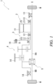
- FIG. 1 is a skeleton parts diagram illustrating a power transmission device 1.
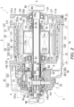
- FIG. 2 is a schematic sectional view illustrating the power transmission device 1.
- FIG. 3 is an enlarged view around the planetary reduction gear 4 of the power transmission device 1.
- FIG. 4 is an enlarged view around the differential mechanism 5 of the power transmission device 1.
- the power transmission device 1 has a motor 2, a planetary reduction gear 4 (reduction mechanism), and a differential mechanism 5.
- the power transmission device 1 also has drive shafts 9A and 9B and a park lock mechanism 3.
- the park lock mechanism 3, the planetary reduction gear 4, the differential mechanism 5, and the drive shafts 9A and 9B are provided.
- the planetary reduction gear 4 is connected downstream of the motor 2.
- the differential mechanism 5 is connected downstream of the planetary reduction gear 4.
- the drive shafts 9A and 9B are connected downstream of the differential mechanism 5.
- the drive shafts 9A and 9B are respectively connected to one side and the other side of the rotation axis X of the differential mechanism 5.
- the axis lines of the drive shafts 9A and 9B are coaxial with the rotation axis X of the motor 2.
- Each of the drive shafts 9A and 9B are connected to left and right drive wheels W of the vehicle.
- Motor 2 is a rotary electric machine having at least one of an electric motor function and a power generation function.
- the output rotation of the motor 2 is reduced by the planetary reduction gear 4 and input to the differential mechanism 5.
- the differential mechanism 5 transmits rotation to the drive wheels W through the drive shafts 9A and 9B.
- the main box 10 of the power transmission device 1 has a first box 11 that houses the motor 2 and a second box 12 that is extrapolated from the first box 11.
- the main box 10 also has a third box 13 that is assembled to the first box 11 and a fourth box 14 that is assembled to the second box 12.
- the first box 11 has a cylindrical support wall portion 111 and a flange-like joint portion 112 provided at one end 111a of the support wall portion 111.
- the first box 11 is provided in a direction in which the support wall portion 111 is aligned with the rotation axis X of the motor 2.
- the motor 2 is accommodated inside the support wall portion 111.
- the joint portion 112 is provided in a direction perpendicular to the rotation axis X.
- the joint portion 112 is formed with a larger outer diameter than the support wall portion 111.
- the second box 12 has a cylindrical circumferential wall portion 121, a flange-like joint portion 122 provided at one end 121a of the circumferential wall portion 121, and a flange-like joint portion 123 provided at the other end 121b of the circumferential wall portion 121.
- the circumferential wall portion 121 is formed with an inner diameter that can be fitted over the support wall portion 111 of the first box 11.
- the first box 11 and the second box 12 are assembled by fitting the circumferential wall portion 121 of the second box 12 over the support wall portion 111 of the first box 11.
- the joint portion 122 on the end 121a side of the circumferential wall portion 121 is in contact with the joint portion 112 of the first box 11 in the direction of the rotation axis X.
- These joint portions 122 and 112 are connected to each other by bolts (not shown).
- a plurality of grooves 111b are provided on the outer periphery of the support wall portion 111.
- the plurality of grooves 111b are provided at intervals in the direction of the rotation axis X.
- Each of the grooves 111b is provided over the entire circumference in the circumferential direction around the rotation axis X.
- the circumferential wall portion 121 of the second box 12 is inserted into the support wall portion 111 of the first box 11.
- the openings of the grooves 111b are closed by the circumferential wall portion 121.
- a plurality of cooling passages CP through which cooling water flows are formed between the support wall portion 111 and the circumferential wall portion 121.
- ring grooves 111c and 111c are formed on both sides of the area where the grooves 111b are provided.
- the seal rings 113 and 113 are fitted and attached to the ring grooves 111c and 111c, respectively.
- seal rings 113 press-fit into the inner circumference of the circumferential wall portion 121 extrapolated to the support wall portion 111, and seal the gap between the outer circumference of the support wall portion 111 and the inner circumference of the circumferential wall portion 121.
- the other end 121b of the second box 12 has a wall portion 120 extending on the inner diameter side.
- the wall portion 120 is provided in a direction perpendicular to the rotation axis X.
- An opening 120a through which the drive shaft 9A is inserted is provided in an area where the wall portion 120 intersects the rotation axis X.
- a cylindrical motor supporting portion 125 surrounding the opening 120a is provided.
- the motor supporting portion 125 is inserted inside the coil end 253b to be described later.
- the motor supporting portion 125 faces the end portion 21b of the rotor core 21 with a gap in the X-axis direction.
- the circumferential wall portion 121 of the second box 12 has a thicker radial thickness in a lower region in the vertical direction based on the mounting state of the power transmission device 1 on a vehicle than in an upper region.
- an oil pooling portion 128 penetrating in the axial direction of the rotation axis X is provided.
- the oil pooling portion 128 communicates with an axial oil passage 138 provided in the joint portion 132 of the third box 13 through a communication hole 112a.
- the communication hole 112a is provided in the joint portion 112 of the first box 11.
- the third box 13 has a wall portion 130 orthogonal to the rotation axis X.
- a joint portion 132 forming a ring shape when viewed from the direction of the rotation axis X is provided on the outer peripheral portion of the wall portion 130.
- the third box 13 is located on the opposite side (right side in the figure) from the differential mechanism 5 when viewed from the first box 11.
- the joint portion 132 of the third box 13 is joined to the joint portion 112 of the first box 11 from the direction of the rotation axis X.
- the third box 13 and the first box 11 are connected to each other by bolts (not shown). In this state, the opening of the first box 11 on the joint portion 122 side (right side in the figure) of the support wall portion 111 is blocked by the third box 13.
- a through-hole 130a of the drive shaft 9A is provided at the center of the wall portion 130.
- a lip seal RS is provided on the inner circumference of the through-hole 130a.
- the lip seal RS elastically contacts an unillustrated lip portion with the outer circumference of the drive shaft 9A.
- the gap between the inner circumference of the through-hole 130a and the outer circumference of the drive shaft 9A is sealed by the lip seal RS.
- a circumferential wall portion 131 surrounding the through-hole 130a is provided on the side of the first box 11 (left side in the figure) of the wall portion 130.
- the drive shaft 9A is supported by bearing B4 through the inner circumference of the circumferential wall portion 131.
- a motor supporting portion 135 is provided on the motor 2 side (left side in the figure) from the circumferential wall portion 131.
- the motor supporting portion 135 forms a cylindrical shape surrounding the rotation axis X at a distance.
- the connecting wall 136 is formed with a larger outer diameter than the circumferential wall portion 131 on the wall portion 130 side (right side in the figure).
- the connecting wall 136 is provided in the direction along the rotation axis X and extends away from the motor 2.
- the connecting wall 136 connects the motor supporting portion 135 and the wall portion 130 of the third box 13.
- the motor supporting portion 135 is supported by the third box 13 via a connecting wall 136.
- the inside of the motor supporting portion 135 is penetrated by one end 20a of the motor shaft 20 from the motor 2 side to the circumferential wall portion 131 side.
- a bearing B1 is supported on the inner circumference of the motor supporting portion 135.
- the outer circumference of the motor shaft 20 is supported by the motor supporting portion 135 via the bearing B1.
- a lip seal RS is provided in a position adjacent to the bearing B1.
- Oil holes 136a to be described later are opened on the inner circumference of the connecting wall 136 in the third box 13.
- the oil OL flows into the internal space Sc surrounded by the connecting wall 136 through the oil hole 136a.
- the lip seal RS is provided to prevent the oil OL inside the connecting wall 136 from flowing into the motor 2 side.
- the fourth box 14 has a circumferential wall portion 141 that surrounds the outer periphery of the planetary reduction gear 4 and the differential mechanism 5, and a flange-like joint portion 142 provided at the end on the side of the second box 12 in the circumferential wall portion 141.
- the fourth box 14 functions as a box that accommodates the planetary reduction gear 4 and the differential mechanism 5.
- the fourth box 14 is located on the differential mechanism 5 side (left side in the drawing) when viewed from the second box 12.
- the joint portion 142 of the fourth box 14 is joined to the joint portion 123 of the second box 12 from the direction of the rotation axis X.
- the fourth box 14 and the second box 12 are connected to each other by bolts (not shown).
- the inside of the main box 10 of the power transmission device 1 has a motor chamber Sa for accommodating the motor 2, and a gear compartment Sb for accommodating the planetary reduction gear 4 and the differential mechanism 5.
- the motor chamber Sa is formed inside the first box 11, between the wall portion 120 of the second box 12 and the wall portion 130 of the third box 13.
- the gear chamber Sb is formed on the inner diameter side of the fourth box 14, between the wall portion 120 of the second box 12 and the circumferential wall portion 141 of the fourth box 14.
- a plate member 8 is provided inside the gear compartment Sb.
- the plate member 8 is fixed to the fourth box 14.
- the plate member 8 divides the gear compartment Sb into a first gear compartment Sb1 for accommodating the planetary reduction gear 4 and the differential mechanism 5, and a second gear chamber Sb2 for accommodating the park lock mechanism 3.
- the second gear compartment Sb2 is located between the first gear compartment Sb1 and the motor compartment Sa.
- the motor 2 has a motor shaft 20, a rotor core 21, and a stator core 25.
- the motor shaft 20 and rotor core 21 are cylindrical.
- the rotor core 21 is extrapolated onto the motor shaft 20.
- the stator core 25 surrounds the outer circumference of the rotor core 21 at a distance.
- bearings B1 and B1 are extrapolated and fixed on both sides of the rotor core 21.
- the bearing B1 located on one end 20a side of the motor shaft 20 from the rotor core 21 (right side in the figure) is supported by the inner circumference of the motor supporting portion 135 of the third box 13.
- the other bearing B1 located on the other end 20b side is supported by the inner circumference of the cylindrical motor supporting portion 125 of the second box 12.
- the motor supporting portions 135 and 125 are arranged along the inner diameter of the coil ends 253a and 253b described later.
- the motor supporting portions 135 and 125 are arranged facing each other with a gap in the X-axis direction of the rotation shaft between one end portion 21a and the other end portion 21b of the rotor core 21.
- the rotor core 21 is formed by stacking multiple silicon steel plates. Each silicon steel plate is extrapolated onto the motor shaft 20 in a state where relative rotation with the motor shaft 20 is regulated.
- the silicon steel plates From the X-axis direction of rotation of the motor shaft 20, the silicon steel plates form a ring shape. North and south pole magnets (not shown) are alternately provided in the circumferential direction around the rotation axis X on the outer circumference side of the silicon steel plates.
- the stator core 25 surrounding the outer circumference of the rotor core 21 is formed by laminating multiple electromagnetic steel plates.
- the stator core 25 is fixed to the inner circumference of the cylindrical support wall portion 111 of the first box 11.
- Each of the electromagnetic steel plates has a yoke portion 251, a teeth portion 252, and a coil 253.
- the yoke portion 251 is ring-shaped and is fixed to the inner circumference of the support wall portion 111.
- the teeth portion 252 protrudes from the inner circumference of the yoke portion 251 towards the rotor core 21.
- coil 253 is formed by winding a winding (not shown) across multiple teeth portions 252.
- Known copper wire or the like can be used for the winding that forms the coil 253.
- the coil 253 may be configured as a distributed winding wound around each of the multiple teeth portions 252 protruding towards the rotor core 21, or as a concentrated winding.
- the length of the coil 253 in the direction of the rotation axis X is set to be longer than that of the rotor core 21.
- the stator core 25 has coil ends 253a and 253b located at both ends of the coil 253 in the direction of the rotation axis X, which protrude further in the direction of the rotation axis X than the rotor core 21.
- the coil ends 253a and 253b have a symmetrical shape across the teeth portion 252.
- An opening 120a is provided in the wall portion 120 (motor supporting portion 125) of the second box 12.
- the other end 20b of the motor shaft 20 penetrates the opening 120a towards the differential mechanism 5 side (left side in the figure) and is located inside the fourth box 14.
- the other end 20b of the motor shaft 20 faces the side gear 54A with a gap in the direction of the rotation axis X inside the fourth box 14, as will be described later.
- the motor shaft 20 has a step portion 201 in the region located inside the fourth box 14.
- the step portion 201 is located near the motor supporting portion 125.
- the lip seal RS divides the motor chamber Sa that accommodates the motor 2 and the gear chamber Sb inside the fourth box 14.
- Oil OL for lubricating the planetary reduction gear 4 and the differential mechanism 5 is sealed inside the fourth box 14 on the inner diameter side (see Figure 2 ).
- the lip seal RS is provided to prevent the flow of oil OL into the motor chamber Sa.
- the region of the motor shaft 20 from the step portion 201 to the vicinity of the other end 20b is a fitting portion 202 with splines provided on the outer circumference.
- the park gear 30 and the sun gear 41 are spline-fitted on the outer circumference of the fitting portion 202.
- One side surface of the park gear 30 is in contact with the step portion 201 in the direction of the rotation axis X (on the right side in the figure).
- One end 410a of the cylindrical base 410 of the sun gear 41 contacts the other side surface of the park gear 30 in the direction of the rotation axis X (on the left side in the figure).
- a nut N is press-fitted from the direction of the rotation axis X on the other end 410b of the base 410.
- the nut N is screwed onto the other end 20b of the motor shaft 20.
- the sun gear 41 and the park gear 30 are provided to be unable to rotate relative to the motor shaft 20, being sandwiched between the nut N and the step portion 201.
- the sun gear 41 has teeth portion 411 on the outer circumference of the other end 20b side of motor shaft 20.
- a stepped pinion gear 43 with a large diameter gear portion 431 as a pinion gear is engaged with the teeth portion 411 on the outer circumference.
- Stepped pinion gear 43 has a large diameter gear portion 431 that engages with the sun gear 41, and a small diameter gear portion 432 that is smaller than the large diameter gear portion 431.
- the stepped pinion gear 43 is a gear component in which the large diameter gear portion 431 and the small diameter gear portion 432 are provided integrally and arranged parallel to the rotation axis X1 direction.
- the large diameter gear portion 431 is formed with a larger outer diameter R1 than the outer diameter R2 of the small diameter gear portion 432.
- the stepped pinion gear 43 is provided in the direction along the axis X1, and the large diameter gear portion 431 is located on the motor 2 side (right side in the figure) of the small diameter gear portion 432.
- the outer circumference of the small diameter gear portion 432 is engaged with the inner circumference of the ring gear 42.
- the ring gear 42 forms a ring shape that surrounds the rotation axis X at a distance.
- a plurality of engaging teeth 421 protruding radially outward are provided on the outer circumference of the ring gear 42.
- the plurality of engaging teeth 421 are provided at intervals in the circumferential direction around the rotation axis X.
- the engaging teeth 421 are provided on the outer circumference of the ring gear 42. Teeth portion 146a is provided on the support wall portion 146 of the fourth box 14. The engaging teeth 421 are spline-fitted to the teeth portion 146a. The rotation of the ring gear 42 around the rotation axis X is restricted.
- the stepped pinion gear 43 has a through hole 430.
- the through hole 430 penetrates the inner diameter side of the large diameter gear portion 431 and the small diameter gear portion 432 in the axial direction X1.
- the pinion shaft 44 is inserted into the through hole 430.
- Needle bearings NB and NB are provided on the outer circumference of the pinion shaft 44.
- the stepped pinion gear 43 is rotatably supported via the needle bearings NB and NB.
- One needle bearing NB on one side (right side in the figure) in the direction of the rotation axis X supports the inner circumference of the large diameter gear portion 431.
- the other needle bearing NB on the other side (left side in the figure) in the direction of the rotation axis X supports the inner circumference of the small diameter gear portion 432.
- An intermediate spacer MS is interposed between the needle bearings NB and NB.
- the inside of the pinion shaft 44 has internal oil passages 440A and 440B.
- the axial internal oil passage 440A extends from one end 44a (right side in the figure) of the pinion shaft 44 to the inner diameter side of the large diameter gear portion 431 along the axis X1.
- the axial internal oil passage 440B extends from the other end 44b (left side in the figure) of the pinion shaft 44 to the inner diameter side of the small diameter gear portion 432 along the axis X1.
- the pinion shaft 44 has oil holes 441, 442, 443, and 444.
- the oil holes 441 and 442 communicate the axial internal oil passage 440A with the outer circumference of the pinion shaft 44.
- the oil holes 443 and 444 communicate the axial internal oil passage 440B with the outer circumference of the pinion shaft 44.
- Oil hole 441 opens in the region where the needle bearing NB is provided, and the needle bearing NB supports the inner circumference of the large diameter gear portion 431. In the pinion shaft 44, the oil hole 441 opens in the region where the stepped pinion gear 43 is extrapolated. Oil hole 442 opens in the gap CL1 in the axial direction of the large diameter gear portion 431 and the opposing surface 61b of the case member 6 of the differential case 50.
- the oil OL that flows into the axial internal oil passage 440A is discharged radially outward from the oil hole 441.
- the oil OL discharged from the oil hole 441 lubricates the needle bearing NB extrapolated on the pinion shaft 44.
- the oil hole 443 opens into the region where the needle bearing NB supporting the inner circumference of the small diameter gear portion 432 is provided.
- the oil hole 443 opens into the region where the stepped pinion gear 43 is extrapolated.
- the oil hole 444 communicates the axial internal oil passage 440B with the outer circumference of the pinion shaft 44.
- the oil hole 444 opens into the gap CL2 between the side wall 432a of the small diameter gear portion 432 in the X1 axis direction and the plate portion 68 of the case member 6 described later.
- the oil OL that flows into the axial internal oil passage 440B is discharged radially outward from the oil hole 443.
- the oil OL discharged from the oil hole 443 lubricates the needle bearing NB extrapolated on the pinion shaft 44.
- the gap CL2 functions as an oil path that leads the oil OL scraped up by the differential case 50 to the pinion shaft 44.
- the pinion shaft 44 has a first shaft portion 445 on one end 44a side (right side in FIG. 4 ) in the longitudinal direction.
- the first shaft portion 445 is a region that protrudes from the stepped pinion gear 43.
- the first shaft portion 445 is supported by a support hole 61a provided in the case member 6 of the differential case 50.
- the pinion shaft 44 has a second shaft portion 446 on the other end 44b side (left side in FIG. 4 ) in the longitudinal direction.
- the second shaft portion 446 is also a region that protrudes from the stepped pinion gear 43.
- the second shaft portion 446 is supported by a support hole 68a provided in the case member 6 of the differential case 50. As will be described in detail later, the second shaft portion 446 is press-fitted into the support hole 68a.
- the second shaft portion 446 is supported so as to be unable to rotate relative to the case member 6.
- first shaft portion 445 is a region on the end 44a side of the pinion shaft 44 where the stepped pinion gear 43 is not extrapolated.
- the second shaft portion 446 is a region on the other end 44b side of the pinion shaft 44 where the stepped pinion gear 43 is not extrapolated.
- the length in the axial direction X1 of the second shaft portion 446 is longer than that of the first shaft portion 445.
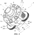
- Figure 5 is a perspective view around the differential case 50 of the differential mechanism 5.
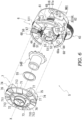
- Figure 6 is an exploded perspective view around the differential case 50 of the differential mechanism 5, exposing the inside of the differential mechanism 5 by omitting one stepped pinion gear 43.
- the differential case 50 as a case accommodates the differential mechanism 5.
- the differential case 50 is formed by assembling the case member 6 (second case member) and the case member 7 (first case member) in the direction of the rotation axis X.
- the case member 6 of the differential case 50 functions as a carrier supporting the pinion shaft 44 of the planetary reduction gear 4.
- three pinion mate gears 52 and pinion mate shaft 51 are provided between the case members 6 and 7 of the differential case 50.
- the pinion mate shaft 51 functions as a support shaft for supporting the pinion mate gears 52.
- the pinion mate shaft 51 has three shaft members 511 provided at equal intervals in the circumferential direction around the rotation axis X (see Figure 6 ).
- each shaft member 511 is connected to a central member 510 arranged on the rotation axis X. That is, the shaft members 511 are arranged radially with respect to the central member 510.
- the pinion mate shaft 51 may be formed integrally with the central member 510 and the shaft members 511.
- Each of the pinion mate gears 52 is extrapolated on each shaft member 511.
- Each of the pinion mate gears 52 is in contact with the central member 510 from the radially outer side of the rotation axis X. In this state, each of the pinion mate gears 52 is rotatably supported by the shaft members 511.
- spherical washers 53 are extrapolated on the shaft members 511.
- the spherical washers 53 are in contact with the spherical outer periphery of the pinion mate gears 52.
- the side gear 54A is located on one side of the central member 510 in the direction of the rotation axis X, and the side gear 54B is located on the other side.
- the side gear 54A is rotatably supported by the case member 6, and the side gear 54B is rotatably supported by the case member 7.
- the side gear 54A engages with three pinion mate gears 52 from one side in the direction of the rotation axis X.
- the side gear 54B engages with three pinion mate gears 52 from the other side in the direction of the rotation axis X.
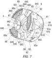
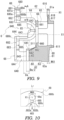
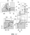
- Figures 7 to 12 are diagrams explaining the case member 6.
- Figure 7 is a perspective view of the case member 6 of the differential mechanism 5 as viewed from the side of the case member 7.
- Figure 8 is a plan view of the case member 6 of the differential mechanism 5 as viewed from the side of the case member 7.
- Figure 9 is a schematic view of the A-A cross-section in Figure 8 , showing the arrangement of the shaft member 511 of the pinion mate shaft 51 in dotted lines.
- Figure 10 is an arrow diagram of the A-A direction in Figure 9 .
- Figure 11 is a schematic view of the A-A cross-section in Figure 8 , omitting the plate member 68 and the connecting beam 62 on the back side of the paper.
- Figure 11 shows the side gear 54A, stepped pinion gear 43, and drive shaft 9A in dotted lines.
- Figure 12 shows the upper region of the rotation axis X in Figure 9 .
- the stepped pinion gear 43 is shown in solid lines.
- the case member 6 has a ring-shaped base 61.
- the base 61 is a plate member having a thickness W61 in the direction of the rotation axis X.
- an opening 60 is provided in the center of the base 61.
- a cylindrical tubular wall portion 611 surrounding the opening 60 is provided on the base 61.
- the cylindrical tubular wall portion 611 is provided on the side opposite (right side in Figure 9 ) to the case member 7 of the base 61.
- the outer circumference of the cylindrical tubular wall portion 611 is supported by a plate member 8 via a bearing B3 (see Figure 2 ).
- the base 61 is provided with three connecting beams 62 that extend toward the case member 7 side.
- the connecting beams 62 are provided on the surface of the base 61 on the case member 7 side (the left side in FIG. 9 ).
- the three connecting beams 62 are provided at equal intervals in the circumferential direction around the rotation axis X (see FIGS. 7 and 8 ).
- the connecting beams 62 have a base 63 that is connected to the base 61.
- the base 63 extends in a direction orthogonal to the base 61.
- the connecting beams 62 have a connecting portion 64 that is connected to the case member 7 side of the base 63 (the left side in the figure).
- the connecting portion 64 is wider than the base 63.
- the connecting portion 64 has a greater width in the circumferential direction around the rotation axis X than the base 63.
- a circular space is formed when viewed from the direction of the rotation axis X.
- the central member 510 of the pinion mate shaft 51, the pinion mate gear 52, and the spherical washer 53 are accommodated in this space.
- the spherical washer 53 is positioned on the outer circumference of the pinion mate gear 52, and the central member 510 is positioned on the inner circumference of the pinion mate gear 52.
- Connecting member 64 is provided at equal intervals in the circumferential direction around the rotation axis X, as shown in Figure 8 .
- Three plate portions 68 are arranged between the connecting portions 64.
- the plate portions 68 extend along the circumferential direction around the rotation axis X and connect the adjacent connecting portions 64.
- the plate portions 68 have an arc shape as viewed from the direction of the rotation axis X.
- the plate portions 68 protrude toward the case member 7 side (left side in the figure) more than the connecting portions 64.
- the plate portions 68 face the base 61 with a gap.
- the stepped pinion gear 43 and pinion shaft 44 are accommodated in this gap (see Figure 5 ).
- a step portion 63a is formed along the circumferential direction around the rotation axis X on the outer peripheral surface of the base 63.
- the case member 6 is divided into a first portion 6A on the case member 7 side (left side in the figure) and a second portion 6B on the base 61 side (right side in the figure) separated by the step portion 63a.
- the diameter of the outer peripheral surface of the second portion 6B is larger than that of the outer peripheral surface of the first portion 6A.
- the weight of the case member 6 is reduced by making the thickness of the first portion 6A in the radial direction of the rotation axis X smaller than the thickness of the second portion 6B.
- the step portion 63a shown in FIG. 7 is formed near the center of the rotation axis X of the base 63 in the X direction. The position where the step portion 63a is formed can be changed appropriately.
- a recess 640 is provided at the center of the direction of the rotation axis X in the circumferential direction of the connecting portion 64. As shown in FIG. 7 , the recess 640 is concave toward the base 61 side with respect to the plate portion 68.
- the recess 640 has a bottom surface portion 643 and a side wall portion 644.
- the arc-shaped bottom surface portion 643 extends along the circumferential direction of the rotation axis X of the recess 640.
- the side wall portion 644 extends in the X direction toward the plate portion 68 from the bottom surface portion 643.
- a groove portion 645 extending in the radial direction of the rotation axis X is formed at the boundary between the bottom surface portion 643 and the side wall portion 644.
- the bottom surface portion 643 of the recess 640 is a surface extending in a direction perpendicular to the rotation axis X.
- a support groove 65 (second cutout portion) for supporting the shaft member 511 of the pinion mate shaft 51 is provided on the bottom surface portion 643.
- the support groove 65 when viewed from the direction of the rotation axis X, is formed linearly along the radius line L of the ring-shaped base 61.
- the support groove 65 transverses the central portion of the recess 640 in the circumferential direction of the rotation axis X from the inner diameter side to the outer diameter side.
- the support groove 65 has a semi-circular shape.
- the support groove 65 is formed by cutting out the bottom surface portion 643 along the outer diameter of the shaft member 511 of the pinion mate shaft 51.
- An arc portion 641 is formed on the inner diameter side (rotation axis X side) of the connecting portion 64, along the outer circumference of the pinion mate gear 52.
- the outer circumference of the pinion mate gear 52 is supported by a spherical washer 53.
- an oil groove 642 is provided in the direction along the above-mentioned radius line L.
- the oil groove 642 is provided in the range from the support groove 65 that supports the shaft member 511 to the gear support portion 66 fixed to the inner circumference of the connecting portion 64.
- the gear support portion 66 is connected to the boundary between the base 63 and the connecting portion 64.
- the gear support portion 66 is provided in a direction perpendicular to the rotation axis X and has a through hole 660 in the central portion.
- the outer circumference of the gear support portion 66 is connected to the inner circumference of three connecting portions 64.
- the center of the through hole 660 is located on the rotation axis X.
- a recess 661 is provided on the side opposite to the base 61 (left side in the figure).
- the recess 661 surrounds the through hole 660.
- a ring-shaped washer 55 is accommodated in the recess 661.
- the washer 55 supports the back surface of the side gear 54A.
- the back surface of the side gear 54A has a cylindrical tubular wall portion 541, and the washer 55 is extrapolated on the tubular wall portion 541.
- three oil grooves 662 are provided on the side of the recess 661 in the gear support portion 66.
- the oil grooves 662 are provided at predetermined intervals in the circumferential direction around the X-axis.
- the oil grooves 662 extend from the inner circumference to the outer circumference of the gear support portion 66 along the radius line L mentioned above.
- the oil grooves 662 are in communication with the oil groove 642 on the arc portion 641 side mentioned above.
- the support hole 61a for the pinion shaft 44 is opened in the base 61.
- the support hole 61a opens into the region between the connecting beams 62, 62 arranged at intervals in the circumferential direction around the X-axis.
- the boss portion 616 surrounding the support hole 61a is provided in the base 61.
- the washer Wc (see Figure 11 ) extrapolated from the pinion shaft 44 is in contact with the boss portion 616 from the X-axis direction of rotation.
- an oil groove 617 is provided in the range from the central opening 60 to the boss portion 616.
- the oil groove 617 is formed in a tapered shape with a gradually narrowing width in the circumferential direction around the X-axis as it approaches the boss portion 616.
- the oil groove 617 is in communication with the oil groove 618 provided in the boss portion 616.
- bolt holes 67, 67 are provided on both sides of the support groove 65.
- the connecting portion 74 on the case member 7 side is joined to the connecting portion 64 on the case member 6 from the X-axis direction of rotation.
- the case members 6 and 7 are joined to each other by bolts B (see Figure 5 ).
- the bolt B penetrates through the connecting portion 74 on the case member 7 side and is screwed into the bolt hole 67.
- the plate portion 68 is composed of an arc-shaped base 680 and an outer circumferential wall portion 681 provided on the outer peripheral edge of the base 680 when viewed from the X-axis direction of rotation.
- the base 680 is a plate member arranged along the thickness direction in the X-axis direction of rotation.
- One end surface 680a and the other end surface 680b of the base 680 in the X-axis direction of rotation are flat surfaces perpendicular to the X-axis of rotation.
- the outer circumferential wall portion 681 protrudes from one end surface 680a of the base 680 in the X-axis direction of rotation.
- the outer circumferential wall portion 681 is formed over the entire length of the base 680 in the circumferential direction around the rotation axis X when viewed from the X-axis direction.
- the inner circumferential surface 681a of the outer circumferential wall portion 681 is formed to overlap with a virtual circle Im1 having a diameter D1.
- the inner circumferential surface 680c of the base 680 is formed to overlap with a virtual circle Im2 having a diameter D2.
- a support hole 68a penetrating the base 680 in the X-axis direction of rotation is formed in the plate portion 68.
- the support hole 68a and the support hole 61a are concentrically arranged along the axis X1 parallel to the rotation axis X.
- the support hole 68a is formed in the central portion of the base 680 in the circumferential direction around the rotation axis X.
- the region on the inner diameter side of the support hole 68a in the base 680 of the plate portion 68 forms an oil receiving portion 682 (see Figure 9 ).
- the oil receiving portion 682 receives oil OL scraped up by the rotation of differential case 50.
- end face 680a, the other end face 680b, and the inner circumferential surface 680c of the base 680 on the inner diameter side of the support hole 68a are also referred to as the end face 680a, the other end face 680b, and the inner circumferential surface 680c of the oil receiving portion 682.
- a recess 683 is provided on the inner circumferential surface 680c of the oil receiving portion 682.
- the recess 683 is formed by cutting out the central portion of the circumferential direction around the rotation axis X of the inner circumferential surface 680c.
- the recess 683 When viewed from the direction of the rotation axis X, the recess 683 is open towards the radial inner diameter side.
- the recess 683 has inclined surfaces 683a and 683b.
- the inclined surfaces 683a and 683b have a decreasing circumferential opening width W68 towards the outer diameter side from the inner circumferential surface 680c.
- the inclined surface 683a and the inclined surface 683b of the recess 683 intersect at vertex P.
- the vertex P is located on a diameter line Lr passing through the rotation axis X and the axis line X1.
- the inner circumferential surface 680c and the recess 683 of the oil receiving portion 682 are inclined to be located on the radial outer side as they go from one end surface 680a to the other end surface 680b in the direction of the rotation axis X.
- the inclined surfaces 683a and 683b of the recess 683 are also inclined to be located on the radial outer side as they go from one end surface 680a to the other end surface 680b in the direction of the rotation axis X.
- an oil groove 685 is formed on the other end face 680b of the oil receiving portion 682 in the direction of the rotation axis X.
- the oil groove 685 connects the recess 683 and the support hole 68a.
- the oil groove 685 extends linearly along the diameter line Lr from the vertex P of the recess 683 (see FIG. 10 ).
- the assembly of the stepped pinion gear 43 to the case member 6 is carried out by placing the stepped pinion gear 43 in the space between the base 61 and the plate portion 68 in the direction of the rotation axis X.
- the pinion shaft 44 is inserted from the support hole 61a side (arrow direction in the figure).
- a washer Wc is interposed between the large diameter gear portion 431 and the base 61 in the direction of the rotation axis X.
- a washer Wc is also interposed between the small diameter gear portion 432 and the base 680.
- One end 44a and the other end 44b of the pinion shaft 44 are supported by support holes 61a and 68a, respectively.
- the diameter of the support hole 61a is set slightly larger than the outer diameter of the pinion shaft 44.
- the diameter of the support hole 68a is set to approximately match the outer diameter of the pinion shaft 44.
- At the other end 44b of the pinion shaft 44 it is press-fitted into the support hole 68a.
- the stepped pinion gear 43 is extrapolated onto the pinion shaft 44 and is supported so as to be rotatable around the axis X1 by the pinion shaft 44.
- a gap CL2 is formed in the area of the base 680 where the oil groove 685 of the oil receiving portion 682 is formed.
- the gap CL2 is formed between the oil groove 685 in the direction of the rotation axis X and the side wall 432a of the small diameter gear portion 432, with the washer Wc sandwiched in between.
- the oil hole 444 of the pinion shaft 44 opens into the gap CL2.
- the case member 7 (shown in a virtual line) is attached to the case member 6 from the plate portion 68 side in the direction of the rotation axis X.
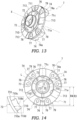
- Figures 13 to 20 are parts diagrams illustrating the case member 7.
- Figure 13 is a perspective view of the case member 7 viewed from the opposite side of the case member 6.
- Figure 14 is a plan view of the case member 7 viewed from the opposite side of the case member 6.
- Figure 15 is a perspective view of the case member 7 viewed from the side of the case member 6.
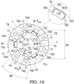
- Figure 16 is a plan view of the case member 7 viewed from the side of the case member 6.
- the guide portion 78 is hatched to make its position easier to understand.
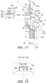
- Figure 17 is a schematic diagram of the A-A cross-section in Figure 16 .
- the arrangement of the pinion mate gear 52 is shown in dashed lines in Figure 17 .
- the boundary between the oil hole 710 and the guide portion 78 is shown in broken lines to make it easier to understand.
- Figure 18 is an A-A arrow view of Figure 17 .
- Cross-hatching is used in Figure 18 to make the position of the guide portion 78 easier to understand.
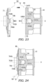
- Figure 19 is a schematic diagram of the A-A cross-section in Figure 16 .
- the illustration of the connecting portion 74 on the far side of the page is omitted in Figure 19 .
- the stepped pinion gear 43, plate portion 68, side gear 54B, and drive shaft 9B are shown in dashed lines.
- Figure 20 is a schematic diagram of the A-A cross-section in Figure 19 .
- the case member 7 has a ring-shaped base 71 (plate) when viewed from the direction of the rotation axis X.
- the base 71 is a plate member having a thickness W71 (see Figure 19 ) in the direction of the rotation axis X.
- a through-hole 70 is provided in the central portion of the base 71.
- the through-hole 70 passes through the base 71 in the thickness direction.
- the diameter (2R4, see Figure 14 ) of the outer circumferential surface 71c of the base 71 is slightly smaller than the diameter D1 of a virtual circle Im1 (see Figure 8 ) (2R4 ⁇ D1).
- the virtual circle Im1 is formed along the inner circumferential surface 681a of the outer circumferential wall portion 681 of the plate portion 68 as described above.
- one end surface 71a and the other end surface 71b of the base 71 in the direction of the rotation axis X are flat surfaces perpendicular to the rotation axis X.
- a tubular wall portion 72 and a guide portion 73 are provided on one end face 71a of the base 71.
- the tubular wall portion 72 surrounds a through-hole 70
- the guide portion 73 surrounds the tubular wall portion 72.
- the guide portion 73 is annular when viewed from the direction of the rotation axis X.
- three ribs 711 are provided on the inner diameter side of the guide portion 73 of the base 71.
- the three ribs 711 are provided at intervals in the circumferential direction around the rotation axis X.
- These ribs 711 are formed on one end face 71a of the base 71, and extend linearly in the radial direction of the rotation axis X.
- the ribs 711 are provided so as to span across the outer diameter side guide portion 73 and the inner diameter side tubular wall portion 72.
- oil holes 710 (openings) penetrating through the base 71 in the thickness direction are provided between the three ribs 711 arranged in the circumferential direction around the rotation axis X.
- the oil holes 710 are opened on the outer and inner sides of the differential case 50 in the direction of the rotation axis X.
- three ribs 713 are provided on the outer diameter side of the guide portion 73 at the base 71.
- the three ribs 713 are provided with intervals in the circumferential direction around the rotation axis X.
- These ribs 713 are formed on one end surface 71a of the base 71.
- the ribs 713 extend linearly in the radial direction of the rotation axis X from the guide portion 73 toward the outer circumferential surface 71c of the base 71.
- Bolt accommodating portions 76, 76 which are recessed toward the back of the paper, are provided on the base 71 between adjacent ribs 713. These bolt accommodating portions 76, 76 are provided in positions that are symmetric with respect to a radius line L. The bolt accommodating portion 76 is opened on the outer circumferential surface 71c of the base 71.
- a bolt insertion hole 77 is opened inside the bolt accommodating portion 76.
- the insertion hole 77 penetrates through the base 71 in the thickness direction (direction of rotation axis X).
- the three ribs 713 are formed on the outer diameter side of the oil holes 710 in the radial direction of the rotation axis X.
- oil holes 710 in the case member 7 are provided at intervals in the circumferential direction around the rotation axis X.
- the oil holes 710 have a substantially rectangular shape when viewed from the direction of the rotation axis X.
- the oil holes 710 are composed of long sides 710a and 710b that extend along the circumferential direction around the rotation axis X, and short sides 710c and 710d that connect the end portions of these long-side portions 710a and 710b.
- the long-side portion 710a is positioned on the outer diameter side relative to the long-side portion 710b.
- three guide portions 78 are provided on the other end surface 71b on the case member 6 side at the base 71.
- the three guide portions 78 surround oil holes 710, and are arranged at intervals in the circumferential direction around the rotation axis X.
- each guide portion 78 is continuous walls that surround the oil holes 710 and open toward the inner diameter side. Specifically, as shown in the enlarged area of Figure 15 , each guide portion 78 includes a long wall portion 781 that extends along the long side portion 710a of the oil hole 710, and short wall portions 783 and 784 that extend along the short side portions 710c and 710d of the oil hole 710.
- the long wall portion 781 and the short wall portions 783 and 784 are formed integrally.
- the outer circumferential surface 781b of the long wall portion 781 overlaps with a virtual circle Im3 having a diameter D4.
- the diameter D4 of the virtual circle Im3 is smaller than the diameter D2 of a virtual circle Im2 (see Figure 8 ).
- the virtual circle Im2 extends along the inner circumferential surface 680c of the base 680 in the plate portion 68 of the case member 6, as mentioned above.
- the long wall portion 781 of the guide portions 78 is a curved wall extending in the circumferential direction around the rotation axis X.
- the short wall portions 783 and 784 extend radially inward from both ends of the long wall portion 781 in the circumferential direction around the rotation axis X.
- the short wall portions 783 and 784 extend linearly along lines Lm2 and Lm3, respectively.
- the lines Lm2 and Lm3 are parallel to a line Lm1.
- the line Lm1 is a straight line passing through the rotation axis X and the midpoint C of the inner circumferential surface 781a of the long wall portion 781 in the circumferential direction around the rotation axis X.
- the inner circumferential surface 781a of the long wall portion 781 and the inner circumferential surfaces 783a and 784a of the short wall portions 783 and 784 are located in front of the broken line relative to the paper surface.
- the long side portion 710a of the oil hole 710 and the short wall portions 783 and 784 are located behind the broken line relative to the paper surface.
- the inner circumferential surface 781a is connected to the long side portion 710a without any step.
- the inner circumferential surfaces 783a and 784a are connected to the short side portions 710d and 710c, respectively, without any step.
- the guide portions 73 and 78 extend in a direction away from the base 71 in the direction of the rotation axis X.
- the inner circumferential surface 731 of the guide portion 73 is a flat surface parallel to the rotation axis X.
- the long-side portion 710a of the oil hole 710 is connected to the inner circumferential surface 731 of the guide portion 73 on the end surface 71a side of the base 71 in the direction of the rotation axis X.
- the long-side portion 710a of the oil hole 710 is an inclined surface.
- the long-side portion 710a is inclined so as to be positioned on the outer diameter side as it moves away from the inner circumferential surface 731 of the guide portion 73 in the direction of the rotation axis X.
- the long-side portion 710a of the oil hole 710 is connected to the inner circumferential surface 781a of the long wall portion 781 of the guide portion 78 on the other end surface 71b side of the base 71 in the direction of the rotation axis X.
- the inner circumferential surface 781a of the long wall portion 781 of the guide portion 78 is an inclined surface.
- the inner circumferential surface 781a is inclined so as to be positioned on the outer diameter side as it moves away from the inner circumferential surface 731 of the guide portion 73 in the direction of the rotation axis X.
- the inclination angle of the inner circumferential surface 781a of the long wall portion 781 is the same as the inclination angle of the long-side portion 710a of the oil hole 710.
- the connecting portions 74 are provided at equal intervals in the circumferential direction around the rotation axis X. As shown in Figure 15 , the connecting portions 74 have a leading end surface 743 protruding toward the case member 6 side. The connecting portions 74 also have side wall portions 744 connecting both end portions in the circumferential direction around the rotation axis X of the leading end surface 743 and the base 71.
- the connecting portions 74 have a circumferential width W2.
- the recess 640 of the connecting portion 64 on the case member 6 side has a circumferential width W1 (see Figure 5 ).
- the width W2 is smaller than the width W1.
- the width W1 refers to the length from the side wall portion 644 connected to one end in the circumferential direction around the rotation axis X of the bottom surface portion 643 to the side wall portion 644 connected to the other end.
- the width W2 refers to the length from the side wall portion 744 connected to one end in the circumferential direction around the rotation axis X of the leading end surface 743 to the side wall portion 744 connected to the other end.
- the leading end surface 743 of the connecting portions 74 is a curved surface extending along the circumferential direction of the rotation axis X when viewed from the direction of the rotation axis X.
- the side wall portion 744 extends from the leading end surface 743 toward the base 71 in the direction of the rotation axis X.
- the bolt insertion hole 77 opens in the leading end surface 743, and one end of the bolt insertion hole 77 opens to the bolt accommodating portion 76 (see Figure 13 ), penetrating through the base 71 in the thickness direction (the direction of the rotation axis X). The other end of the penetration hole 77 opens in the leading end surface 743.
- a support groove 75 (first cutout portion) is provided in the leading end surface 743.
- the support groove 75 supports the pinion mate shaft 51.
- the support groove 75 is formed between the bolt insertion holes 77 in the circumferential direction of the rotation axis X.
- the support groove 75 when viewed from the direction of the rotation axis X, is formed linearly along the radius line L of the base 71.
- the support groove 75 is formed by crossing the connecting portion 74 from the inner diameter side to the outer diameter side.
- the support groove 75 is semi-circular.
- the support groove 75 is formed by cutting out the leading end surface 743 along the outer diameter of the shaft member 511.
- the outer circumferential surface 74a of the connecting portion 74 protrudes radially outward from the outer circumferential surface 71c of the base 71 in the direction of the rotation axis X.
- the outer circumferential surface 74a of the connecting portion 74 and the outer circumferential surface 71c of the base 71 are connected by a step portion 79. That is, the step portion 79 is provided on the outer circumferential surface of the boundary between the connecting portion 74 and the base 71.
- the outer circumferential surface 74a is located on the connecting portion 74 side of the step portion 79, and the outer circumferential surface 71c is located on the base 71 side.
- the radius R3 of the outer circumferential surface 74a is longer than the radius R4 of the outer circumferential surface 71c.
- R3 and R4 respectively denote the radius from the rotation axis X.
- an arc portion 741 is provided on the inner diameter side (rotation axis X side) of the connecting portion 74.
- the arc portion 741 follows the outer circumference of the pinion mate gear 52.
- an oil groove 742 is provided along the above-mentioned radius line L.
- the oil groove 742 is provided in the range from the support groove 75 of the shaft member 511 to the base 71 located on the inner circumference of the connecting portion 74.
- the oil groove 742 communicates with an oil groove 712 provided in the other end surface 71b of the base 71. As shown in Figure 16 , the oil groove 712 is provided along the radius line L when viewed from the direction of the rotation axis X. The oil groove 712 is formed up to the through-hole 70 provided in the base 71.
- a ring-shaped washer 55 is placed on the other end surface 71b of the base 71.
- the washer 55 supports the back surface of the side gear 54B.
- a cylindrical tubular wall portion 540 is provided on the back surface of the side gear 54B. The washer 55 is extrapolated to the tubular wall portion 540.
- an oil groove 721 is formed on the inner circumference of a tubular wall portion 72 surrounding the through-hole 70.
- the oil groove 721 is formed at a position where it intersects with the oil groove 712.
- the oil groove 721 is provided along the direction of the rotation axis X, over the entire length of the tubular wall portion 72 in the direction of the rotation axis X.
- Figure 21 is a parts diagram illustrating the assembly of the case members 6 and 7.
- Figure 22 is a parts diagram illustrating the assembly of the case members 6 and 7.
- Figure 21 shows the state before the assembly of the case members 6 and 7, while Figure 22 shows the state after the assembly of the case members 6 and 7.
- Figures 21 and 22 show the differential case 50 viewed from the A-A direction in Figure 4 . Hatching is applied to the connecting portions 64 and 74 for ease of viewing.
- the shaft member 511 of the pinion mate shaft 51 is shown in dashed lines in Figures 21 and 22 .
- the differential case 50 is constructed by assembling the case members 6 and 7 in the direction of the rotation axis X. That is, the direction of the rotation axis X follows the assembly direction of the differential case 50.
- the connecting portion 74 (convex portion) of the case member 7 is inserted into the recess 640 of the connecting portion 64 of the case member 6.
- the length L2 of the side wall portion 744 of the case member 7 in the direction of the rotation axis X matches the length L1 of the side wall portion 644 of the case member 6 in the direction of the rotation axis X. Therefore, as shown in Figure 22 , the leading end surface 743 of the connecting portion 74 inserted into the recess 640 contacts the bottom surface portion 643. This determines the position of the case members 7 and 6 in the direction of the rotation axis X.
- the outer circumferential surface 71c of the base 71 of the case member 7 is fitted into the inner circumferential surface 681a of the outer circumferential wall portion 681 on the plate portion 68 of the case member 6.
- the case members 7 and 6 are concentrically arranged on the rotation axis X.
- case members 6 and 7 are joined to each other by bolts B (see Figure 5 ) that penetrate through the connecting portion 74 on the side of the case member 7 and are screwed into bolt holes 67 and 67 on the side of the case member 6.
- the support grooves 65 of the bottom surface portion 643 and 75 of the leading end surface 743 are formed at positions that overlap when viewed from the direction of the rotation axis X.
- the semi-circular support grooves 65 and 75 face each other.
- the support grooves 65 and 75 are symmetrical with respect to a line that passes through the bottom surface portion 643 and the leading end surface 743.
- the opening of the support grooves 65 and 75 communicate with each other, forming a circular hole along the outer diameter of the shaft member 511 as a whole. The shaft member 511 is inserted and held in this circular hole.
- the width W1 in the circumferential direction around the rotation axis X of the recess 640 is greater than the width W2 in the circumferential direction around the connecting portion 74 (W1>W2). Therefore, as shown in Figure 22 , the side wall portion 644 of the recess 640 faces the side wall portion 744 of the connecting portion 74 with a gap therebetween. This gap forms an oil passage 56 that communicates with the inside and outside of the differential case 50.
- the oil passage 56 is formed on both end sides of the connecting portion 74 in the circumferential direction around the rotation axis X.
- the circumferential width of each oil passage 56 around the rotation axis X is (W1 - W2)/2.
- the oil passage 56 is located between the recess 640 and the connecting portion 74 in the circumferential direction around the rotation axis X of the differential case 50.
- the position of the oil passage 56 is indicated by hatching on the case member 6.
- the oil passage 56 extends from the inner diameter side end of the connecting portion 64 to the outside in the radial direction of the rotation axis X and opens to the outer circumferential surface of the differential case 50.
- the pinion mate gear 52 and the side gear 54B are accommodated on the inner diameter side of the connecting portion 64.
- the oil OL that the pinion mate gear 52 and the side gear 54B have stirred flows into the inner diameter side end of the oil passage 56.
- the oil passage 56 discharges the oil OL to the outside of the differential case 50 by centrifugal force.
- the oil passage 56 has a longitudinal shape extending in the direction of the rotation axis X.
- a groove portion 645 is located at one end of the oil passage 56 in the direction of the rotation axis X.
- the groove portion 645 is formed at the boundary between the bottom surface portion 643 and the side wall portion 644.
- the groove portion 645 extends in the radial direction of the rotation axis X.
- the base 71 of the case member 7 is located at the other end of the oil passage 56 in the direction of the rotation axis X.
- the outer circumferential surface 71c of the base 71 of the case member 7 is fitted into the inner circumferential surface 681a of the outer circumferential wall portion 681 of the plate portion 68 of the case member 6.
- the guide portion 78 of the case member 7 is disposed on the inner diameter side of the oil receiving portion 682 of the case member 6. In this state, the leading end surface 78a of the guide portion 78 is located between one end surface 680a and the other end surface 680b of the oil receiving portion 682 in the direction of the rotation axis X.
- the guide portion 78 of the case member 7, the oil receiving portion 682 of the case member 6, and the pinion shaft 44 overlap in the radial direction of the rotation axis X.
- Figure 20 shows a diameter line Lr passing through the rotation axis X and the axis line X1.
- the oil hole 710 of the case member 7, the guide portion 78, the recess 683 of the case member 6, the oil groove 685, the oil hole 444 of the pinion shaft 44, and the axial internal oil passage 440B are arranged in order along the diameter line Lr.
- the oil hole 710, the guide portion 78, the recess 683, the oil groove 685, the oil hole 444, and the axial internal oil passage 440B overlap with each other.
- the vertex P of the recess 683 is located on the diameter line Lr.
- the differential case 50 has the bearing B2 extrapolated to the tubular wall portion 72 of the case member 7.
- the bearing B2 is in contact with the inner race on the step portion 722 provided on the outer circumference of the tubular wall portion 72 from the direction of the rotation axis X.
- the bearing B2 extrapolated to the tubular wall portion 72 is held by the support portion 145 of the fourth box 14.
- the tubular wall portion 72 of the differential case 50 is rotatably supported by the fourth box 14 (see Figure 4 ) through the bearing B2.
- the drive shaft 9B penetrating the opening 145a of the support portion 145 of the fourth box 14 is inserted from the direction of the rotation axis X and is rotatably supported by the support portion 145.
- the tubular wall portion 72 functions as a shaft support portion that supports the outer circumference of the drive shaft 9B.
- a lip seal RS is fixed to the inner circumference of the opening 145a.
- the unillustrated lip portion of the lip seal RS elastically contacts the outer circumference of the tubular wall portion 540 of the side gear 54B extrapolated to the drive shaft 9B.
- the case member 6 of the differential case 50 is supported by the plate member 8 via a bearing B3 extrapolated to the tubular wall portion 611 (see Figure 2 ).
- a drive shaft 9A that penetrates through the through-hole 130a of the third box 13 is inserted from the direction of the rotation axis X.
- the drive shaft 9A is provided to cross the motor shaft 20 of the motor 2 and the inner diameter side of the sun gear 41 of the planetary reduction gear 4 in the direction of the rotation axis X.
- the side gears 54A and 54B are splined to the outer circumference of the leading end portions of the drive shafts 9A and 9B.
- the side gears 54A and 54B are integrally rotatably connected to the drive shafts 9A and 9B around the rotation axis X.
- the side gears 54A and 54B are arranged opposite to each other with a gap in the direction of the rotation axis X.
- the central member 510 of the pinion mate shaft 51 is positioned between the side gears 54A and 54B.
- three shaft members 511 of the pinion mate shaft 51 extend radially outward from the central member 510.
- a pinion mate gear 52 is supported on each of the shaft members 511 of the pinion mate shaft 51.
- the side gear 54A is positioned on one side of the rotation axis X of the pinion mate gear 52, and the side gear 54B is positioned on the other side.
- the pinion mate gears 52 are assembled in a state where their teeth portions are engaged with each other on the side gears 54A and 54B.
- the inside of the fourth box 14 stores lubricating oil OL.
- the lower side of the differential case 50 is located within the stored oil OL.
- the stored oil OL is stored up to the height at which, for example, the connecting beam 62 is located within the oil OL when the connecting beam 62 is located at the lowest position.
- the stored oil OL is scraped up by the differential case 50 rotating around the rotation axis X during the transmission of the output rotation of the motor 2.
- an oil catch portion 15 is provided above the fourth box 14. Part of the oil OL scraped up by the differential case 50 rotating around the rotation axis X flows into the oil catch portion 15.
- the oil catch portion 15 is connected to an oil passage 151a that extends on the inner diameter side of the fourth box 14. As shown in Figure 2 , the inner diameter end of the oil passage 151a is opened between the lip seal RS and the bearing B2.
- the oil catch portion 15 is also connected to an oil hole 136a (see Figure 2 ) provided in the cylindrical connecting wall 136 of the third box 13 via an unillustrated piping.
- the third box 13 has a radial oil passage 137 that communicates with the internal space Sc.
- the radial oil passage 137 extends radially downward from the internal space Sc.
- the radial oil passage 137 communicates with a axial oil passage 138 provided in the joint portion 132.
- a communication hole 112a is provided in the joint portion 112 of the first box 11.
- the axial oil passage 138 communicates with an oil pooling portion 128 provided in the lower part of the second box 12 via the communication hole 112a.
- the oil pooling portion 128 passes through the circumferential wall portion 121 in the direction of the rotation axis X.
- the oil pooling portion 128 communicates with the second gear chamber Sb2 provided in the fourth box 14.
- the power transmission device 1 includes a planetary reduction gear 4, a differential mechanism 5, and drive shafts 9A and 9B provided along the transmission path of the output rotation of the motor 2.
- the sun gear 41 serves as the input part of the output rotation of the motor 2 in the planetary reduction gear 4.
- the differential case 50 supporting the stepped pinion gear 43 serves as the output part of the input rotation.
- the stepped pinion gear 43 (large diameter gear portion 431, small diameter gear portion 432) rotates about the axis line X1 with the input rotation from the sun gear 41 side.
- the small diameter gear portion 432 of the stepped pinion gear 43 is engaged with the ring gear 42 fixed to the inner circumference of the fourth box 14. Therefore, while the stepped pinion gear 43 rotates about the axis line X1, it revolves around the rotation axis X.
- the drive shaft 9B is located on the inner circumference of the revolving orbit of the stepped pinion gear 43.
- the outer diameter R2 of the small diameter gear portion 432 of the stepped pinion gear 43 is smaller than the outer diameter R1 of the large diameter gear portion 431 (see Figure 3 ).
- the differential case 50 (case members 6 and 7) supporting the stepped pinion gear 43 rotates about the rotation axis X at a lower rotational speed than the input rotation from the motor 2.
- lubricating oil OL is stored inside the fourth box 14 for lubrication purposes. Therefore, the stored oil OL is scraped up by the differential case 50 rotating around the rotation axis X when transmitting the output rotation of the motor 2.
- the scraped-up oil OL lubricates the engagement portions between the sun gear 41 and the large diameter gear portion 431, between the small diameter gear portion 432 and the ring gear 42, and between the pinion mate gear 52 and the side gears 54A and 54B. Much of the oil OL scraped up by the differential case 50 flows into the oil catch portion 15.
- the inner diameter side end portion of the oil passage 151a is opened to the inner circumference of the support portion 145 (refer to FIG. 2 ). Therefore, the oil OL flowing into the oil passage 151a is discharged into a clearance Rx between the inner circumference of the support portion 145 of the fourth box 14 and the tubular wall portion 540 of the side gear 54B.
- Oil OL discharged into the clearance Rx lubricates the bearing B2 supported by the support portion 145.
- the oil OL that lubricates the bearing B2 moves to the outer side (bearing B2 side) of the differential case 50 by the centrifugal force of the rotation of the differential case 50.
- a guide portion 73 that forms a ring shape when viewed from the direction of the rotation axis X is provided. Therefore, the oil OL that has moved to the outer diameter side is captured by a portion of the guide portion 73.
- ribs 711 are provided on the inner circumferential side of the guide portion 73.
- a recess is formed between the guide portion 73, the ribs 711, and the tubular wall portion 72. This recess makes it easier for the oil OL to accumulate on the inner circumferential side of the guide portion 73.
- oil holes 710 are provided along the inner circumferential surface 731 of the guide portion 73 at the base 71 of the case member 7.
- the oil OL is prevented from further moving to the outer diameter side by the guide portion 73.
- the oil OL whose movement is obstructed passes through the oil hole 710 that opens to the inner circumference of the guide portion 73 to the case member 6 side.
- the oil OL reaches the inner circumferential surface 731 of the guide portion 73 by the centrifugal force generated by the rotation of the differential case 50. Many of the oil OL that have reached the inner circumferential surface 731 of the guide portion 73 flow into the oil hole 710 that opens in the direction of the rotation axis X without passing over the guide portion 73.
- the oil OL supplied to the oil hole 710 moves to the guide portion 78.
- the long side portion 710a of the oil hole 710 and the inner circumferential surface 781a of the long wall portion 781 of the guide portion 78 are inclined to the radial outer side as they move away from the inner circumferential surface 731 of the guide portion 73 in the direction of the rotation axis X.
- the oil OL passing through the oil hole 710 and the guide portion 78 moves along the inclination while being subjected to centrifugal force. This promotes the movement of the oil OL towards the case member 6 side.
- this inclination it is possible to reduce the re-entry of the oil OL that has moved from the guide portion 73 to the case member 6 side back to the guide portion 73, and discharge it to the outside of the differential case 50.
- the guide portion 78 is a continuous wall composed of a long wall portion 781, short wall portions 783 and 784 (see Figure 18 ).
- the guide portion 78 opens toward the inner diameter side. This allows the guide portion 78 to catch not only the oil OL flowing from the oil hole 710 but also the oil OL that scatters inside the differential case 50 (white arrow in Figure 19 ).
- the oil OL that has moved from the oil hole 710 to the case member 6 side through the guide portion 78 is discharged from the leading end surface 78a.
- the inner circumferential surface 680c of the oil receiving portion 682 and the recess 683 are transversely arranged from the base 71 side of the case member 7 to the pinion gear 43 side along the direction of the rotation axis X at the leading end surface 78a of the guide portion 78.
- the inner circumferential surface 680c and the recess 683 are inclined in the radial direction outward as they move away from the guide portion 78 along the direction of the rotation axis X.
- the oil OL caught in the recess 683 moves along the inclination from one end surface 680a side to the other end surface 680b side of the oil receiving portion 682.
- many of the oil OL caught on the inner circumferential surface 680c gather in the recess 683 during the movement along the inclination.
- the recess 683 communicates with the oil groove 685 (clearance CL2) at the vertex P.
- the oil OL in the recess 683 is gathered at the vertex P by centrifugal force and then discharged into the oil groove 685.
- the oil OL in the oil groove 685 moves radially outward by centrifugal force and flows into the oil hole 444 of the pinion shaft 44.
- the washer Wc is also lubricated by the oil OL.
- the oil OL flowing into the oil hole 444 of the pinion shaft 44 moves to the axial internal oil passage 440B and is finally discharged from the oil hole 443 (see Figure 4 ). At this time, the oil OL lubricates the needle bearing NB.
- the oil OL passes through the oil groove 712 provided at the base 71 of the case member 7 and the oil groove 742 provided on the arc portion 741.
- the oil OL that has passed through the oil groove 742 is supplied to the spherical washer 53 that supports the back surface of the pinion mate gear 52 to lubricate the spherical washer 53.
- the oil OL discharged into the internal space Sc from the oil hole 136a is stored in the internal space Sc.
- the oil OL also lubricates the bearing B4 supported by the circumferential wall portion 131 of the third box 13.
- a portion of the oil OL discharged into the internal space Sc moves to the other end 20b side of the motor shaft 20 through the gap between the outer circumference of the drive shaft 9A and the inner circumference of the motor shaft 20.
- the other end 20b of the motor shaft 20 is inserted inside the tubular wall portion 541 of the side gear 54A.
- a communication passage 542 communicating with the back surface of the side gear 54A is provided on the inner circumference of the tubular wall portion 541.
- the oil OL that lubricates the washer 55 on the back surface of the side gear 54A moves through the oil groove 662 provided on the gear support portion 66 of the case member 6 and the oil groove 642 provided on the arc portion 641.
- the oil OL that has passed through the oil groove 642 is supplied to the spherical washer 53 that supports the back surface of the pinion mate gear 52 to lubricate the spherical washer 53.
- the internal space Sc of the third box 13 communicates with the second gear chamber Sb2 provided in the fourth box 14 through the radial oil passage 137, the axial oil passage 138, the communication hole 112a, and the oil pooling portion 128 provided in the lower part of the second box 12.
- the oil OL in the internal space Sc is held at the same height position as the stored oil OL in the fourth box 14.
- the oil OL is supplied from the oil catch portion 15 to the support portion 145 of the fourth box 14 to lubricate the bearing B2.
- the oil OL is also supplied to the internal space Sc of the third box 13 to lubricate the bearing B4.
- the oil OL in the fourth box 14 is swept up when the drive wheels W rotate and used for lubricating bearings and gear engagement parts.
- the oil OL used for lubrication is returned to the fourth box 14 and becomes available for sweeping up again.
- the support groove 65 and the support groove 75 face each other to form a circular hole that supports the shaft member 511.
- the shaft member 511 can be assembled with the case members 6 and 7 while being pre-arranged in the support groove 65 of the recess 640.
- three shaft members 511 can be pre-connected to the central member 510 and arranged in the case member 6.
- a pinion mate shaft 51 which is integrally molded with the shaft member 511 and the central member 510, can also be used.
- the circumferential width W2 of the connecting portion 74 around the rotation axis X is set smaller than the circumferential width W1 of the recess 640. Therefore, the connecting portion 74 is easier to insert into the recess 640.
- a groove portion 645 is formed at the boundary between the bottom surface portion 643 and the side wall portion 644 of the case member 6.
- This groove portion 645 extends along the oil passage 56 from the inner diameter side to the outer diameter side of the rotation axis X.
- the oil OL stirred by the pinion mate gear 52 and the side gears 54A and 54B enters the groove portion 645 and flows along the outer diameter side of the groove portion 645. This improves the discharge performance of the oil OL from the inside to the outside of the differential case 50.
- One example of the power transmission device 1 in one aspect of the present invention is listed below:
- the shaft member 511 is supported by the connecting portion 74 in the recess 640.
- the shaft member 511 is pre-arranged in the recess 640 of the case member 6.
- the connecting portion 74 of the case member 7 is inserted into the recess 640 and brought into contact with the shaft member 511, and the case member 6 and the case member 7 are assembled. This improves the freedom of assembly compared to simply inserting the shaft member 511 into the hole of the differential case 50.
- the assembly may be performed by inserting the shaft member 511 into the circular hole formed by the support grooves 65 and 75.
- the shaft member 511 and the central member 510 of the pinion mate shaft 51 are molded separately.
- the central member 510 is pre-arranged in the case member 6 together with the pinion mate gear 52 and the spherical washer 53, and the case member 7 is then assembled. Thereafter, the shaft member 511 is inserted into the circular hole and connected to the central member 510.
- the case member 7 preferably has a support groove 75 (first cutout portion) on the leading end surface 743 (leading end) of the connecting portion 74.
- the shaft member 511 is accommodated in the support groove 75.
- the shaft member 511 is supported in the recess 640 while being accommodated in the support groove 75 of the connecting portion 74. This makes it possible to stably support the shaft member 511.
- the case member 6 preferably has a support groove 65 (second cutout portion) for accommodating the shaft member 511 in the recess 640.
- the shaft member 511 is supported in the recess 640 while being accommodated in the support groove 65 of the recess 640. This makes it possible to stably support the shaft member 511. Furthermore, when the support groove 65 is provided in addition to the support groove 75, the shaft member 511 is accommodated in the support grooves 75 and 65 from both sides in the direction of the rotation axis X, and the shaft member 511 can be stably supported.
- the support grooves 65 and 75 can be formed as semi-circular cutouts that are symmetrical with respect to the contact surfaces (leading end surface 743 and bottom surface portion 643).
- the power transmission device 1 preferably has an oil passage 56 between the recess 640 and the connecting portion 74 in the circumferential direction (circumferential direction) around the rotation axis X of the differential case 50.
- the oil passage 56 opens on the outer circumferential surface of the differential case 50.
- the power transmission device By configuring the power transmission device in this way, it becomes easier to discharge oil OL from the inside to the outside of the differential case 50 via the oil passage 56, thereby reducing the agitation resistance of the oil OL of the pinion mate gear 52 arranged inside the differential case 50.
- the width W1 in the circumferential direction around the rotation axis X of the recess 640 is set larger than the width W2 in the circumferential direction around the connecting portion 74.
- this gap is used as the oil passage 56. This eliminates the need to separately form the oil passage 56, thereby reducing manufacturing costs.
- oil passage 56 is not limited to the gap between the side wall portion 644 and the side wall portion 744, and may be separately formed.
- the oil passage 56 preferably has an elongated shape extending in the longitudinal direction of the rotation axis X.
- the oil passage 56 located between the recess 640 and the connecting portion 74 has a longitudinal shape that extends in the direction of the rotation axis X, which allows for clearance between the recess 640 and the connecting portion 74. This makes it easier to insert the connecting portion 74 into the recess 640 and to assemble the case members 6 and 7.
- the power transmission device 1 preferably has multiple shaft members 511.
- the power transmission device 1 preferably has three or more shaft members 511.
- the power transmission device 1 preferably has a pinion mate shaft 51 comprising multiple shaft members 511 and a central member 510 that supports the multiple shafts.
- the shaft members 511 and the central member 510 in the case member 6 in advance by connecting them, and perform the assembly. This improves the freedom of assembly.
- the state of pre-connecting the shaft members 511 and the central member 510 includes a case where the shaft members 511 and the central member 510 are integrally molded.
- the assembly efficiency can be improved.
- the case member 7 preferably has a base 71 (plate).
- the base 71 is connected to the connecting portion 74 and fitted to the case member 6.
- the case member 6 has a plate portion 68 that connects to the recess 640 of the connecting portion 64.
- the base 71 is provided on the side away from the case member 6 of the connecting portion 74.
- the plate portion 68 is provided on the side of the case member 7 of the recess 640.
- the case member 7 preferably has a step portion 79 provided on the outer circumferential surface at the boundary between the base 71 and the connecting portion 74.
- the radius R4 of the outer circumferential surface 71c on the base 71 side at the step portion 79 is smaller than the radius R3 of the outer circumferential surface 74a on the connecting portion 74 side.
- the connecting portion 74 side of the case member 7 that supports the shaft member 511 is made thick to increase its rigidity, while the base 71 side, where rigidity is not required, is made thin, enabling the differential case 50 to be lightweight.
- the case member 6 preferably has
- the case member 6 has a step portion 63a on the outer circumferential surface at the boundary between the first portion 6A and the second portion 6B.
- Figure 23 is a parts diagram illustrating the assembly of case members 6 and 7 in deformation example 1.
- Figure 24 is a parts diagram illustrating the assembly of case members 6 and 7 in deformation example 1.
- Figure 23 shows the state before assembly
- Figure 24 shows the state after assembly
- the case member 6 has a recess 640A that recesses in the direction of the rotation axis X.
- the case member 7 has a connecting portion 74A which is a protrusion in the direction of the rotation axis X.
- a support groove for supporting the shaft member 511 is not formed in the recess 640A and the connecting portion 74A.
- the recess 640A of the case member 6 has a bottom surface portion 643A and side wall portions 644A which connect to both ends in the circumferential direction around the rotation axis X of the bottom surface portion 643A.
- the bottom surface portion 643A is formed in a cross-sectional arc shape along the outer diameter of the shaft member 511.
- the connecting portion 74A of the case member 7 has a leading end surface 743A and side wall portions 744A.
- the side wall portions 744A are connected to both ends in the circumferential direction around the rotation axis X of the leading end surface 743A.
- the width W10 of the circumferential direction of the recess 640A is set larger than the width W20 of the circumferential direction of the connecting portion 74A. That is, the connecting portion 74A can be inserted into the recess 640A.
- the width W10 means the length from one side wall portion 644A connected to the bottom surface portion 643A to the other side wall portion 644A.
- the width W20 means the length from one side wall portion 744A connected to the leading end surface 743A to the other side wall portion 744A.
- the length L20 of the connecting portion 74A in the direction of the rotation axis X matches the length L10 shown in the case member 6.
- the length L10 means the length from the tangent line Im10 passing through the outer peripheral edge closest to the case member 7 of the shaft member 511 to the end on the case member 7 side of the side wall portion 644A.
- the assembly of the case members 6 and 7 can be performed by placing the shaft member 511 in advance in the recess 640A of the case member 6.
- the shaft member 511 is placed in contact with the bottom surface portion 643A.
- the connecting portion 74A is inserted into the recess 640A, the leading end surface 743A of the connecting portion 74A comes into contact with the outer peripheral edge of the shaft member 511.
- the shaft member 511 is supported in the recess 640A in a state of being sandwiched between the bottom surface portion 643A and the leading end surface 743A (refer to Figure 24 ).
- the power transmission device 1 has a connecting portion 74A (protrusion) that protrudes in the direction of the rotation axis X and is provided in the case member 7, and a recess 640A that is provided in the case member 6 and sinks in the direction of the rotation axis X.
- the shaft member 511 is supported by the connecting portion 74A in the recess 640A.
- This configuration improves the degree of freedom in assembly, as in the embodiment.
- the present invention is not limited to this embodiment.
- the power transmission device can also be applied to something other than a vehicle.
Landscapes
- Engineering & Computer Science (AREA)
- General Engineering & Computer Science (AREA)
- Mechanical Engineering (AREA)
- Chemical & Material Sciences (AREA)
- Combustion & Propulsion (AREA)
- Transportation (AREA)
- Retarders (AREA)
- General Details Of Gearings (AREA)
Abstract
Description
- The present invention relates to a power transmission device.
-
Patent Documents 1 discloses a power transmission device with a bevel gear differential mechanism. The differential mechanism includes a pinion mate gear and a pinion mate shaft housed in a differential case. - Patent Document 1 :
WO 2004/076891 A1 - It is desirable to improve the freedom of assembly for the power transmission device.
- A power transmission device according to one aspect of the present invention includes;
- a case formed by assembling a first case member and a second case member, and
- a shaft member supported in the case; wherein
- the first case member has a protrusion protruding in the axial direction along the assembly direction of the case,
- the second case member has a recess being recessed in the axial direction, and
- the shaft member is supported by the protrusion in the recess.
- According to one aspect of the present invention, the freedom of assembly can be improved.
-
- [
FIG. 1] FIG. 1 is a skeleton parts diagram illustrating a power transmission device. - [
FIG. 2] FIG. 2 is a schematic cross-sectional view illustrating the power transmission device. - [
FIG. 3] FIG. 3 is an enlarged view around the planetary reduction gear of the power transmission device. - [
FIG. 4] FIG. 4 is an enlarged view around the differential mechanism of the power transmission device. - [
FIG. 5] FIG. 5 is a perspective view of the differential case of the differential mechanism. - [
FIG. 6] FIG. 6 is an exploded perspective view of the differential case of the differential mechanism. - [
FIG. 7] FIG. 7 is a perspective view of thecase member 6 of the differential mechanism viewed from thecase member 7 side. - [
FIG. 8] FIG. 8 is a plan view of thecase member 6 of the differential mechanism viewed from thecase member 7 side. - [
FIG. 9] FIG. 9 is a schematic view of the A-A section inFIG. 8 . - [
FIG. 10] FIG. 10 is an arrow view of the A-A section inFIG. 9 . - [
FIG. 11] FIG. 11 is a schematic view of the A-A section inFIG. 8 . - [
FIG. 12] FIG. 12 shows the upper region of the rotation axis X inFIG. 9 and the stepped pinion gear in solid lines. - [
FIG. 13] FIG. 13 is a perspective view of thecase member 7 viewed from the opposite side of thecase member 6. - [
FIG. 14] FIG. 14 is a plan view of thecase member 7 viewed from the opposite side of thecase member 6. - [
FIG. 15] FIG. 15 is a perspective view of thecase member 7 viewed from thecase member 6 side. - [
FIG. 16] FIG. 16 is a plan view of thecase member 7 viewed from thecase member 6 side. - [
FIG. 17] FIG. 17 is a schematic view of the A-A section inFIG. 16 . - [
FIG. 18] FIG. 18 is an arrow view of the A-A section inFIG. 17 . - [
FIG. 19] FIG. 19 is a schematic view of the A-A section inFIG. 16 . - [
FIG. 20] FIG. 20 is a schematic view of the A-A section inFIG. 19 . - [
FIG. 21] FIG. 21 is a parts diagram illustrating the assembly of thecase member 6 and thecase member 7. - [
FIG. 22] FIG. 22 is a parts diagram illustrating the assembly of thecase member 6 and thecase member 7. - [
FIG. 23] FIG. 23 is a parts diagram illustrating the assembly of thecase member 6 and thecase member 7 according to the first modification. - [
FIG. 24] FIG. 24 is a parts diagram illustrating the assembly of thecase member 6 and thecase member 7 according to the first modification. - First, definitions of terms used in this specification will be described. A power transmission device is a device that has at least a power transmission mechanism. The power transmission device can be, for example, a gear mechanism and/or a differential gear mechanism.
- When a second element (component, part, etc.) connected to a first element (component, part, etc.), a second element (component, part, etc.) connected downstream of the first element (component, part, etc.), or a second element (component, part, etc.) connected upstream of the first element (component, part, etc.) is mentioned, it means that the first and second elements are connected for power transmission. The input side of power is upstream, and the output side of power is downstream. The first and second elements may be connected via other elements (clutch, other gear mechanism, etc.).
- "Overlap in a predetermined direction of view" means that multiple elements are arranged in a predetermined direction, and "overlap in a predetermined direction" is equivalent to this description. "Predetermined direction" can be, for example, axial direction, radial direction, gravity direction, vehicle travel direction (forward direction or backward direction of the vehicle), and the like.
- If multiple elements (components, parts, etc.) are shown arranged in a predetermined direction on the drawings, it may be assumed that there is a description in the specification explaining that they overlap in a predetermined direction of view.
- "Not overlapping in a predetermined direction of view" or "offset in a predetermined direction of view" means that multiple elements are not arranged in a predetermined direction, and "not overlapping in a predetermined direction" or "offset in a predetermined direction" is equivalent to this description. "Predetermined direction" can be, for example, axial direction, radial direction, gravity direction, vehicle travel direction (forward direction or backward direction of the vehicle), and the like.
- If multiple elements (components, parts, etc.) are shown not arranged in a predetermined direction on the drawings, it may be assumed that there is a description in the specification explaining that they do not overlap in a predetermined direction of view.
- The phrase "in a predetermined direction of view, the first element (component, part, etc.) is positioned between the second element (component, part, etc.) and the third element (component, part, etc.)" means that when observed from the predetermined direction, the first element can be observed to be located between the second and third elements. The "predetermined direction" refers to the axial direction, radial direction, gravity direction, vehicle travel direction (forward or backward), etc.
- For example, if the second element, first element, and third element are arranged in that order along the axial direction, the first element can be said to be positioned between the second and third elements when viewed radially. If it is shown in the drawings that the first element is located between the second and third elements in a predetermined direction of view, it can be assumed that the description in the specification explains that the first element is positioned between the second and third elements in the predetermined direction of view.
- When two elements (parts, components, etc.) overlap in the axial direction, the two elements are coaxial.
- "Axial direction" refers to the axial direction of the rotating axis of the components that make up the power transmission device. "Radial direction" refers to the direction perpendicular to the rotating axis of the components that make up the power transmission device. Examples of components include motors, gear mechanisms, differential gear mechanisms, etc.
- The rotation elements (such as sun gear, carrier, ring gear) of the planetary gear mechanism are "fixed" to other elements, which means that they can be directly fixed or fixed via another member.
- The following describes embodiments of the present invention.
-
FIG. 1 is a skeleton parts diagram illustrating apower transmission device 1. -
FIG. 2 is a schematic sectional view illustrating thepower transmission device 1. -
FIG. 3 is an enlarged view around theplanetary reduction gear 4 of thepower transmission device 1. -
FIG. 4 is an enlarged view around thedifferential mechanism 5 of thepower transmission device 1. - As shown in
Figure 1 , thepower transmission device 1 has amotor 2, a planetary reduction gear 4 (reduction mechanism), and adifferential mechanism 5. Thepower transmission device 1 also hasdrive shafts park lock mechanism 3. - Along the transmission path of the output rotation of the
motor 2 around its rotation axis X, thepark lock mechanism 3, theplanetary reduction gear 4, thedifferential mechanism 5, and thedrive shafts planetary reduction gear 4 is connected downstream of themotor 2. Thedifferential mechanism 5 is connected downstream of theplanetary reduction gear 4. Thedrive shafts differential mechanism 5. Thedrive shafts differential mechanism 5. The axis lines of thedrive shafts motor 2. Each of thedrive shafts -
Motor 2 is a rotary electric machine having at least one of an electric motor function and a power generation function. In thepower transmission device 1, the output rotation of themotor 2 is reduced by theplanetary reduction gear 4 and input to thedifferential mechanism 5. Thedifferential mechanism 5 transmits rotation to the drive wheels W through thedrive shafts - As shown in
Figure 2 , themain box 10 of thepower transmission device 1 has afirst box 11 that houses themotor 2 and asecond box 12 that is extrapolated from thefirst box 11. Themain box 10 also has athird box 13 that is assembled to thefirst box 11 and afourth box 14 that is assembled to thesecond box 12. - The
first box 11 has a cylindricalsupport wall portion 111 and a flange-like joint portion 112 provided at oneend 111a of thesupport wall portion 111. - The
first box 11 is provided in a direction in which thesupport wall portion 111 is aligned with the rotation axis X of themotor 2. Themotor 2 is accommodated inside thesupport wall portion 111. - The joint portion 112 is provided in a direction perpendicular to the rotation axis X. The joint portion 112 is formed with a larger outer diameter than the
support wall portion 111. - The
second box 12 has a cylindricalcircumferential wall portion 121, a flange-likejoint portion 122 provided at oneend 121a of thecircumferential wall portion 121, and a flange-likejoint portion 123 provided at theother end 121b of thecircumferential wall portion 121. - The
circumferential wall portion 121 is formed with an inner diameter that can be fitted over thesupport wall portion 111 of thefirst box 11. - The
first box 11 and thesecond box 12 are assembled by fitting thecircumferential wall portion 121 of thesecond box 12 over thesupport wall portion 111 of thefirst box 11. - The
joint portion 122 on theend 121a side of thecircumferential wall portion 121 is in contact with the joint portion 112 of thefirst box 11 in the direction of the rotation axis X. Thesejoint portions 122 and 112 are connected to each other by bolts (not shown). - In the
first box 11, a plurality ofgrooves 111b are provided on the outer periphery of thesupport wall portion 111. The plurality ofgrooves 111b are provided at intervals in the direction of the rotation axis X. Each of thegrooves 111b is provided over the entire circumference in the circumferential direction around the rotation axis X. - The
circumferential wall portion 121 of thesecond box 12 is inserted into thesupport wall portion 111 of thefirst box 11. The openings of thegrooves 111b are closed by thecircumferential wall portion 121. A plurality of cooling passages CP through which cooling water flows are formed between thesupport wall portion 111 and thecircumferential wall portion 121. - On the outer circumference of the
support wall portion 111 of thefirst box 11,ring grooves grooves 111b are provided. The seal rings 113 and 113 are fitted and attached to thering grooves - These seal rings 113 press-fit into the inner circumference of the
circumferential wall portion 121 extrapolated to thesupport wall portion 111, and seal the gap between the outer circumference of thesupport wall portion 111 and the inner circumference of thecircumferential wall portion 121. - The
other end 121b of thesecond box 12 has awall portion 120 extending on the inner diameter side. Thewall portion 120 is provided in a direction perpendicular to the rotation axis X. Anopening 120a through which thedrive shaft 9A is inserted is provided in an area where thewall portion 120 intersects the rotation axis X. - On the side (right side in the figure) of the
motor 2 in thewall portion 120, a cylindricalmotor supporting portion 125 surrounding theopening 120a is provided. - The
motor supporting portion 125 is inserted inside thecoil end 253b to be described later. Themotor supporting portion 125 faces theend portion 21b of therotor core 21 with a gap in the X-axis direction. - The
circumferential wall portion 121 of thesecond box 12 has a thicker radial thickness in a lower region in the vertical direction based on the mounting state of thepower transmission device 1 on a vehicle than in an upper region. - In this region with a thicker radial thickness, an
oil pooling portion 128 penetrating in the axial direction of the rotation axis X is provided. - The
oil pooling portion 128 communicates with anaxial oil passage 138 provided in thejoint portion 132 of thethird box 13 through acommunication hole 112a. Thecommunication hole 112a is provided in the joint portion 112 of thefirst box 11. - The
third box 13 has awall portion 130 orthogonal to the rotation axis X. Ajoint portion 132 forming a ring shape when viewed from the direction of the rotation axis X is provided on the outer peripheral portion of thewall portion 130. - The
third box 13 is located on the opposite side (right side in the figure) from thedifferential mechanism 5 when viewed from thefirst box 11. Thejoint portion 132 of thethird box 13 is joined to the joint portion 112 of thefirst box 11 from the direction of the rotation axis X. Thethird box 13 and thefirst box 11 are connected to each other by bolts (not shown). In this state, the opening of thefirst box 11 on thejoint portion 122 side (right side in the figure) of thesupport wall portion 111 is blocked by thethird box 13. - In the
third box 13, a through-hole 130a of thedrive shaft 9A is provided at the center of thewall portion 130. - A lip seal RS is provided on the inner circumference of the through-
hole 130a. The lip seal RS elastically contacts an unillustrated lip portion with the outer circumference of thedrive shaft 9A. The gap between the inner circumference of the through-hole 130a and the outer circumference of thedrive shaft 9A is sealed by the lip seal RS. - On the side of the first box 11 (left side in the figure) of the
wall portion 130, acircumferential wall portion 131 surrounding the through-hole 130a is provided. Thedrive shaft 9A is supported by bearing B4 through the inner circumference of thecircumferential wall portion 131. - A
motor supporting portion 135 is provided on themotor 2 side (left side in the figure) from thecircumferential wall portion 131. Themotor supporting portion 135 forms a cylindrical shape surrounding the rotation axis X at a distance. - On the outer periphery of the
motor supporting portion 135, acylindrical connecting wall 136 is connected. The connectingwall 136 is formed with a larger outer diameter than thecircumferential wall portion 131 on thewall portion 130 side (right side in the figure). The connectingwall 136 is provided in the direction along the rotation axis X and extends away from themotor 2. The connectingwall 136 connects themotor supporting portion 135 and thewall portion 130 of thethird box 13. - The
motor supporting portion 135 is supported by thethird box 13 via a connectingwall 136. The inside of themotor supporting portion 135 is penetrated by oneend 20a of themotor shaft 20 from themotor 2 side to thecircumferential wall portion 131 side. - A bearing B1 is supported on the inner circumference of the
motor supporting portion 135. The outer circumference of themotor shaft 20 is supported by themotor supporting portion 135 via the bearing B1. - A lip seal RS is provided in a position adjacent to the bearing B1.
-
Oil holes 136a to be described later are opened on the inner circumference of the connectingwall 136 in thethird box 13. The oil OL flows into the internal space Sc surrounded by the connectingwall 136 through theoil hole 136a. The lip seal RS is provided to prevent the oil OL inside the connectingwall 136 from flowing into themotor 2 side. - The
fourth box 14 has acircumferential wall portion 141 that surrounds the outer periphery of theplanetary reduction gear 4 and thedifferential mechanism 5, and a flange-likejoint portion 142 provided at the end on the side of thesecond box 12 in thecircumferential wall portion 141. Thefourth box 14 functions as a box that accommodates theplanetary reduction gear 4 and thedifferential mechanism 5. - The
fourth box 14 is located on thedifferential mechanism 5 side (left side in the drawing) when viewed from thesecond box 12. Thejoint portion 142 of thefourth box 14 is joined to thejoint portion 123 of thesecond box 12 from the direction of the rotation axis X. Thefourth box 14 and thesecond box 12 are connected to each other by bolts (not shown). - The inside of the
main box 10 of thepower transmission device 1 has a motor chamber Sa for accommodating themotor 2, and a gear compartment Sb for accommodating theplanetary reduction gear 4 and thedifferential mechanism 5. - The motor chamber Sa is formed inside the
first box 11, between thewall portion 120 of thesecond box 12 and thewall portion 130 of thethird box 13. - The gear chamber Sb is formed on the inner diameter side of the
fourth box 14, between thewall portion 120 of thesecond box 12 and thecircumferential wall portion 141 of thefourth box 14. - A
plate member 8 is provided inside the gear compartment Sb. Theplate member 8 is fixed to thefourth box 14. - The
plate member 8 divides the gear compartment Sb into a first gear compartment Sb1 for accommodating theplanetary reduction gear 4 and thedifferential mechanism 5, and a second gear chamber Sb2 for accommodating thepark lock mechanism 3. - In the direction of the rotation axis X, the second gear compartment Sb2 is located between the first gear compartment Sb1 and the motor compartment Sa.
- The
motor 2 has amotor shaft 20, arotor core 21, and astator core 25. Themotor shaft 20 androtor core 21 are cylindrical. Therotor core 21 is extrapolated onto themotor shaft 20. Thestator core 25 surrounds the outer circumference of therotor core 21 at a distance. - On the
motor shaft 20, bearings B1 and B1 are extrapolated and fixed on both sides of therotor core 21. - The bearing B1 located on one
end 20a side of themotor shaft 20 from the rotor core 21 (right side in the figure) is supported by the inner circumference of themotor supporting portion 135 of thethird box 13. The other bearing B1 located on theother end 20b side is supported by the inner circumference of the cylindricalmotor supporting portion 125 of thesecond box 12. - The
motor supporting portions motor supporting portions end portion 21a and theother end portion 21b of therotor core 21. - The
rotor core 21 is formed by stacking multiple silicon steel plates. Each silicon steel plate is extrapolated onto themotor shaft 20 in a state where relative rotation with themotor shaft 20 is regulated. - From the X-axis direction of rotation of the
motor shaft 20, the silicon steel plates form a ring shape. North and south pole magnets (not shown) are alternately provided in the circumferential direction around the rotation axis X on the outer circumference side of the silicon steel plates. - The
stator core 25 surrounding the outer circumference of therotor core 21 is formed by laminating multiple electromagnetic steel plates. Thestator core 25 is fixed to the inner circumference of the cylindricalsupport wall portion 111 of thefirst box 11. - Each of the electromagnetic steel plates has a
yoke portion 251, ateeth portion 252, and acoil 253. Theyoke portion 251 is ring-shaped and is fixed to the inner circumference of thesupport wall portion 111. Theteeth portion 252 protrudes from the inner circumference of theyoke portion 251 towards therotor core 21. - For example,
coil 253 is formed by winding a winding (not shown) acrossmultiple teeth portions 252. Known copper wire or the like can be used for the winding that forms thecoil 253. Thecoil 253 may be configured as a distributed winding wound around each of themultiple teeth portions 252 protruding towards therotor core 21, or as a concentrated winding. - In the
stator core 25, the length of thecoil 253 in the direction of the rotation axis X is set to be longer than that of therotor core 21. Thestator core 25 has coil ends 253a and 253b located at both ends of thecoil 253 in the direction of the rotation axis X, which protrude further in the direction of the rotation axis X than therotor core 21. The coil ends 253a and 253b have a symmetrical shape across theteeth portion 252. - An
opening 120a is provided in the wall portion 120 (motor supporting portion 125) of thesecond box 12. Theother end 20b of themotor shaft 20 penetrates theopening 120a towards thedifferential mechanism 5 side (left side in the figure) and is located inside thefourth box 14. - The
other end 20b of themotor shaft 20 faces theside gear 54A with a gap in the direction of the rotation axis X inside thefourth box 14, as will be described later. - As shown in
Figure 3 , themotor shaft 20 has astep portion 201 in the region located inside thefourth box 14. Thestep portion 201 is located near themotor supporting portion 125. A lip seal RS supported by the inner circumference of themotor supporting portion 125 contacts the outer circumference of the area between thestep portion 201 and the bearing B1. - The lip seal RS divides the motor chamber Sa that accommodates the
motor 2 and the gear chamber Sb inside thefourth box 14. - Oil OL for lubricating the
planetary reduction gear 4 and thedifferential mechanism 5 is sealed inside thefourth box 14 on the inner diameter side (seeFigure 2 ). - The lip seal RS is provided to prevent the flow of oil OL into the motor chamber Sa.
- As shown in
Figure 3 , the region of themotor shaft 20 from thestep portion 201 to the vicinity of theother end 20b is afitting portion 202 with splines provided on the outer circumference. - The
park gear 30 and thesun gear 41 are spline-fitted on the outer circumference of thefitting portion 202. - One side surface of the
park gear 30 is in contact with thestep portion 201 in the direction of the rotation axis X (on the right side in the figure). Oneend 410a of the cylindrical base 410 of thesun gear 41 contacts the other side surface of thepark gear 30 in the direction of the rotation axis X (on the left side in the figure). - A nut N is press-fitted from the direction of the rotation axis X on the other end 410b of the base 410. The nut N is screwed onto the
other end 20b of themotor shaft 20. - The
sun gear 41 and thepark gear 30 are provided to be unable to rotate relative to themotor shaft 20, being sandwiched between the nut N and thestep portion 201. - The
sun gear 41 hasteeth portion 411 on the outer circumference of theother end 20b side ofmotor shaft 20. A steppedpinion gear 43 with a largediameter gear portion 431 as a pinion gear is engaged with theteeth portion 411 on the outer circumference. - Stepped
pinion gear 43 has a largediameter gear portion 431 that engages with thesun gear 41, and a smalldiameter gear portion 432 that is smaller than the largediameter gear portion 431. - The stepped
pinion gear 43 is a gear component in which the largediameter gear portion 431 and the smalldiameter gear portion 432 are provided integrally and arranged parallel to the rotation axis X1 direction. - The large
diameter gear portion 431 is formed with a larger outer diameter R1 than the outer diameter R2 of the smalldiameter gear portion 432. - The stepped
pinion gear 43 is provided in the direction along the axis X1, and the largediameter gear portion 431 is located on themotor 2 side (right side in the figure) of the smalldiameter gear portion 432. - The outer circumference of the small
diameter gear portion 432 is engaged with the inner circumference of thering gear 42. Thering gear 42 forms a ring shape that surrounds the rotation axis X at a distance. A plurality of engagingteeth 421 protruding radially outward are provided on the outer circumference of thering gear 42. The plurality of engagingteeth 421 are provided at intervals in the circumferential direction around the rotation axis X. - The engaging
teeth 421 are provided on the outer circumference of thering gear 42.Teeth portion 146a is provided on thesupport wall portion 146 of thefourth box 14. The engagingteeth 421 are spline-fitted to theteeth portion 146a. The rotation of thering gear 42 around the rotation axis X is restricted. - The stepped
pinion gear 43 has a through hole 430. The through hole 430 penetrates the inner diameter side of the largediameter gear portion 431 and the smalldiameter gear portion 432 in the axial direction X1. Thepinion shaft 44 is inserted into the through hole 430. Needle bearings NB and NB are provided on the outer circumference of thepinion shaft 44. The steppedpinion gear 43 is rotatably supported via the needle bearings NB and NB. - One needle bearing NB on one side (right side in the figure) in the direction of the rotation axis X supports the inner circumference of the large
diameter gear portion 431. The other needle bearing NB on the other side (left side in the figure) in the direction of the rotation axis X supports the inner circumference of the smalldiameter gear portion 432. An intermediate spacer MS is interposed between the needle bearings NB and NB. - As shown in
Fig. 4 , the inside of thepinion shaft 44 hasinternal oil passages internal oil passage 440A extends from oneend 44a (right side in the figure) of thepinion shaft 44 to the inner diameter side of the largediameter gear portion 431 along the axis X1. The axialinternal oil passage 440B extends from theother end 44b (left side in the figure) of thepinion shaft 44 to the inner diameter side of the smalldiameter gear portion 432 along the axis X1. - The
pinion shaft 44 hasoil holes internal oil passage 440A with the outer circumference of thepinion shaft 44. The oil holes 443 and 444 communicate the axialinternal oil passage 440B with the outer circumference of thepinion shaft 44. -
Oil hole 441 opens in the region where the needle bearing NB is provided, and the needle bearing NB supports the inner circumference of the largediameter gear portion 431. In thepinion shaft 44, theoil hole 441 opens in the region where the steppedpinion gear 43 is extrapolated.Oil hole 442 opens in the gap CL1 in the axial direction of the largediameter gear portion 431 and the opposingsurface 61b of thecase member 6 of thedifferential case 50. - Oil OL scraped up by the
differential case 50 described later flows into theoil hole 442. The oil OL that flows into theoil hole 442 flows into the axialinternal oil passage 440A of thepinion shaft 44. The oil OL that flows into the axialinternal oil passage 440A is discharged radially outward from theoil hole 441. The oil OL discharged from theoil hole 441 lubricates the needle bearing NB extrapolated on thepinion shaft 44. - Furthermore, the
oil hole 443 opens into the region where the needle bearing NB supporting the inner circumference of the smalldiameter gear portion 432 is provided. In thepinion shaft 44, theoil hole 443 opens into the region where the steppedpinion gear 43 is extrapolated. - The
oil hole 444 communicates the axialinternal oil passage 440B with the outer circumference of thepinion shaft 44. Theoil hole 444 opens into the gap CL2 between theside wall 432a of the smalldiameter gear portion 432 in the X1 axis direction and theplate portion 68 of thecase member 6 described later. - Oil OL scraped up by the
differential case 50 described later flows into the gap CL2 and flows toward the outer diameter side. The oil OL that flows from the gap CL2 into theoil hole 444 flows into the axialinternal oil passage 440B of thepinion shaft 44. The oil OL that flows into the axialinternal oil passage 440B is discharged radially outward from theoil hole 443. The oil OL discharged from theoil hole 443 lubricates the needle bearing NB extrapolated on thepinion shaft 44. In other words, the gap CL2 functions as an oil path that leads the oil OL scraped up by thedifferential case 50 to thepinion shaft 44. - As shown in
FIG. 4 , thepinion shaft 44 has afirst shaft portion 445 on oneend 44a side (right side inFIG. 4 ) in the longitudinal direction. Thefirst shaft portion 445 is a region that protrudes from the steppedpinion gear 43. Thefirst shaft portion 445 is supported by asupport hole 61a provided in thecase member 6 of thedifferential case 50. - The
pinion shaft 44 has asecond shaft portion 446 on theother end 44b side (left side inFIG. 4 ) in the longitudinal direction. Thesecond shaft portion 446 is also a region that protrudes from the steppedpinion gear 43. Thesecond shaft portion 446 is supported by asupport hole 68a provided in thecase member 6 of thedifferential case 50. As will be described in detail later, thesecond shaft portion 446 is press-fitted into thesupport hole 68a. Thesecond shaft portion 446 is supported so as to be unable to rotate relative to thecase member 6. - Here, the
first shaft portion 445 is a region on theend 44a side of thepinion shaft 44 where the steppedpinion gear 43 is not extrapolated. Thesecond shaft portion 446 is a region on theother end 44b side of thepinion shaft 44 where the steppedpinion gear 43 is not extrapolated. - In the
pinion shaft 44, the length in the axial direction X1 of thesecond shaft portion 446 is longer than that of thefirst shaft portion 445. - The main structure of the
differential mechanism 5 will be described below. -
Figure 5 is a perspective view around thedifferential case 50 of thedifferential mechanism 5. -
Figure 6 is an exploded perspective view around thedifferential case 50 of thedifferential mechanism 5, exposing the inside of thedifferential mechanism 5 by omitting one steppedpinion gear 43. - As shown in
Figures 4 to 6 , thedifferential case 50 as a case accommodates thedifferential mechanism 5. Thedifferential case 50 is formed by assembling the case member 6 (second case member) and the case member 7 (first case member) in the direction of the rotation axis X. Thecase member 6 of thedifferential case 50 functions as a carrier supporting thepinion shaft 44 of theplanetary reduction gear 4. - As shown in
Figure 6 , three pinion mate gears 52 andpinion mate shaft 51 are provided between thecase members differential case 50. Thepinion mate shaft 51 functions as a support shaft for supporting the pinion mate gears 52. - The
pinion mate shaft 51 has threeshaft members 511 provided at equal intervals in the circumferential direction around the rotation axis X (seeFigure 6 ). - The inner end of each
shaft member 511 is connected to acentral member 510 arranged on the rotation axis X. That is, theshaft members 511 are arranged radially with respect to thecentral member 510. Thepinion mate shaft 51 may be formed integrally with thecentral member 510 and theshaft members 511. - Each of the pinion mate gears 52 is extrapolated on each
shaft member 511. Each of the pinion mate gears 52 is in contact with thecentral member 510 from the radially outer side of the rotation axis X. In this state, each of the pinion mate gears 52 is rotatably supported by theshaft members 511. - As shown in
Figure 4 ,spherical washers 53 are extrapolated on theshaft members 511. Thespherical washers 53 are in contact with the spherical outer periphery of the pinion mate gears 52. - In the
differential case 50, theside gear 54A is located on one side of thecentral member 510 in the direction of the rotation axis X, and theside gear 54B is located on the other side. Theside gear 54A is rotatably supported by thecase member 6, and theside gear 54B is rotatably supported by thecase member 7. - The
side gear 54A engages with three pinion mate gears 52 from one side in the direction of the rotation axis X. Theside gear 54B engages with three pinion mate gears 52 from the other side in the direction of the rotation axis X. -
Figures 7 to 12 are diagrams explaining thecase member 6. -
Figure 7 is a perspective view of thecase member 6 of thedifferential mechanism 5 as viewed from the side of thecase member 7. -
Figure 8 is a plan view of thecase member 6 of thedifferential mechanism 5 as viewed from the side of thecase member 7. - In
Figures 7 and8 , cross-hatching is added to theplate portion 68 for easier viewing. -
Figure 9 is a schematic view of the A-A cross-section inFigure 8 , showing the arrangement of theshaft member 511 of thepinion mate shaft 51 in dotted lines. -
Figure 10 is an arrow diagram of the A-A direction inFigure 9 . -
Figure 11 is a schematic view of the A-A cross-section inFigure 8 , omitting theplate member 68 and the connectingbeam 62 on the back side of the paper.Figure 11 shows theside gear 54A, steppedpinion gear 43, and driveshaft 9A in dotted lines. -
Figure 12 shows the upper region of the rotation axis X inFigure 9 . The steppedpinion gear 43 is shown in solid lines. - As shown in
Figures 7 and9 , thecase member 6 has a ring-shapedbase 61. Thebase 61 is a plate member having a thickness W61 in the direction of the rotation axis X. - As shown in
Figure 9 , anopening 60 is provided in the center of thebase 61. A cylindricaltubular wall portion 611 surrounding theopening 60 is provided on thebase 61. The cylindricaltubular wall portion 611 is provided on the side opposite (right side inFigure 9 ) to thecase member 7 of thebase 61. The outer circumference of the cylindricaltubular wall portion 611 is supported by aplate member 8 via a bearing B3 (seeFigure 2 ). - The
base 61 is provided with three connectingbeams 62 that extend toward thecase member 7 side. The connecting beams 62 are provided on the surface of the base 61 on thecase member 7 side (the left side inFIG. 9 ). - The three connecting
beams 62 are provided at equal intervals in the circumferential direction around the rotation axis X (seeFIGS. 7 and8 ). - As shown in
FIG. 7 , the connectingbeams 62 have a base 63 that is connected to thebase 61. Thebase 63 extends in a direction orthogonal to thebase 61. The connecting beams 62 have a connectingportion 64 that is connected to thecase member 7 side of the base 63 (the left side in the figure). The connectingportion 64 is wider than thebase 63. The connectingportion 64 has a greater width in the circumferential direction around the rotation axis X than thebase 63. - On the inner diameter side of the connecting
portion 64, a circular space is formed when viewed from the direction of the rotation axis X. As shown inFIG. 6 , thecentral member 510 of thepinion mate shaft 51, thepinion mate gear 52, and thespherical washer 53 are accommodated in this space. Thespherical washer 53 is positioned on the outer circumference of thepinion mate gear 52, and thecentral member 510 is positioned on the inner circumference of thepinion mate gear 52. - Connecting
member 64 is provided at equal intervals in the circumferential direction around the rotation axis X, as shown inFigure 8 . Threeplate portions 68 are arranged between the connectingportions 64. Theplate portions 68 extend along the circumferential direction around the rotation axis X and connect the adjacent connectingportions 64. Theplate portions 68 have an arc shape as viewed from the direction of the rotation axis X. As shown inFigure 9 , theplate portions 68 protrude toward thecase member 7 side (left side in the figure) more than the connectingportions 64. Theplate portions 68 face the base 61 with a gap. The steppedpinion gear 43 andpinion shaft 44 are accommodated in this gap (seeFigure 5 ). - As shown in
Figure 7 , astep portion 63a is formed along the circumferential direction around the rotation axis X on the outer peripheral surface of thebase 63. As shown inFigure 4 , thecase member 6 is divided into a first portion 6A on thecase member 7 side (left side in the figure) and asecond portion 6B on the base 61 side (right side in the figure) separated by thestep portion 63a. - The diameter of the outer peripheral surface of the
second portion 6B is larger than that of the outer peripheral surface of the first portion 6A. The weight of thecase member 6 is reduced by making the thickness of the first portion 6A in the radial direction of the rotation axis X smaller than the thickness of thesecond portion 6B. Thestep portion 63a shown inFIG. 7 is formed near the center of the rotation axis X of the base 63 in the X direction. The position where thestep portion 63a is formed can be changed appropriately. - As shown in
FIG. 8 , arecess 640 is provided at the center of the direction of the rotation axis X in the circumferential direction of the connectingportion 64. As shown inFIG. 7 , therecess 640 is concave toward the base 61 side with respect to theplate portion 68. Therecess 640 has abottom surface portion 643 and aside wall portion 644. The arc-shapedbottom surface portion 643 extends along the circumferential direction of the rotation axis X of therecess 640. Theside wall portion 644 extends in the X direction toward theplate portion 68 from thebottom surface portion 643. - A
groove portion 645 extending in the radial direction of the rotation axis X is formed at the boundary between thebottom surface portion 643 and theside wall portion 644. Thebottom surface portion 643 of therecess 640 is a surface extending in a direction perpendicular to the rotation axis X. A support groove 65 (second cutout portion) for supporting theshaft member 511 of thepinion mate shaft 51 is provided on thebottom surface portion 643. - As shown in
FIG. 8 , thesupport groove 65, when viewed from the direction of the rotation axis X, is formed linearly along the radius line L of the ring-shapedbase 61. Thesupport groove 65 transverses the central portion of therecess 640 in the circumferential direction of the rotation axis X from the inner diameter side to the outer diameter side. - As shown in
FIG. 9 , thesupport groove 65 has a semi-circular shape. Thesupport groove 65 is formed by cutting out thebottom surface portion 643 along the outer diameter of theshaft member 511 of thepinion mate shaft 51. Thesupport groove 65 is formed to a depth capable of accommodating half of thecylindrical shaft member 511. That is, thesupport groove 65 is formed to a depth corresponding to half the diameter Da (=Da/2) of theshaft member 511. - An
arc portion 641 is formed on the inner diameter side (rotation axis X side) of the connectingportion 64, along the outer circumference of thepinion mate gear 52. - In the
arc portion 641, the outer circumference of thepinion mate gear 52 is supported by aspherical washer 53. - In the
arc portion 641, anoil groove 642 is provided in the direction along the above-mentioned radius line L. Theoil groove 642 is provided in the range from thesupport groove 65 that supports theshaft member 511 to thegear support portion 66 fixed to the inner circumference of the connectingportion 64. - The
gear support portion 66 is connected to the boundary between the base 63 and the connectingportion 64. Thegear support portion 66 is provided in a direction perpendicular to the rotation axis X and has a throughhole 660 in the central portion. - As shown in
FIG. 8 , the outer circumference of thegear support portion 66 is connected to the inner circumference of three connectingportions 64. In this state, the center of the throughhole 660 is located on the rotation axis X. - As shown in
Figures 9 and11 , in thegear support portion 66, arecess 661 is provided on the side opposite to the base 61 (left side in the figure). Therecess 661 surrounds the throughhole 660. A ring-shapedwasher 55 is accommodated in therecess 661. Thewasher 55 supports the back surface of theside gear 54A. - The back surface of the
side gear 54A has a cylindricaltubular wall portion 541, and thewasher 55 is extrapolated on thetubular wall portion 541. - From the X-axis direction of the rotation axis, three
oil grooves 662 are provided on the side of therecess 661 in thegear support portion 66. Theoil grooves 662 are provided at predetermined intervals in the circumferential direction around the X-axis. - The
oil grooves 662 extend from the inner circumference to the outer circumference of thegear support portion 66 along the radius line L mentioned above. Theoil grooves 662 are in communication with theoil groove 642 on thearc portion 641 side mentioned above. - As shown in
Figures 7 and9 , thesupport hole 61a for thepinion shaft 44 is opened in thebase 61. Thesupport hole 61a opens into the region between the connectingbeams - The
boss portion 616 surrounding thesupport hole 61a is provided in thebase 61. The washer Wc (seeFigure 11 ) extrapolated from thepinion shaft 44 is in contact with theboss portion 616 from the X-axis direction of rotation. - In the
base 61, anoil groove 617 is provided in the range from thecentral opening 60 to theboss portion 616. - As shown in
Figure 7 , theoil groove 617 is formed in a tapered shape with a gradually narrowing width in the circumferential direction around the X-axis as it approaches theboss portion 616. Theoil groove 617 is in communication with theoil groove 618 provided in theboss portion 616. - In the connecting
portion 64, bolt holes 67, 67 are provided on both sides of thesupport groove 65. - As shown in
Figure 6 , the connectingportion 74 on thecase member 7 side is joined to the connectingportion 64 on thecase member 6 from the X-axis direction of rotation. Thecase members Figure 5 ). The bolt B penetrates through the connectingportion 74 on thecase member 7 side and is screwed into thebolt hole 67. - As shown in
Figure 8 , theplate portion 68 is composed of an arc-shapedbase 680 and an outercircumferential wall portion 681 provided on the outer peripheral edge of the base 680 when viewed from the X-axis direction of rotation. - As shown in
Figure 9 , thebase 680 is a plate member arranged along the thickness direction in the X-axis direction of rotation. Oneend surface 680a and theother end surface 680b of the base 680 in the X-axis direction of rotation are flat surfaces perpendicular to the X-axis of rotation. The outercircumferential wall portion 681 protrudes from oneend surface 680a of the base 680 in the X-axis direction of rotation. - As shown in
FIG. 8 , the outercircumferential wall portion 681 is formed over the entire length of the base 680 in the circumferential direction around the rotation axis X when viewed from the X-axis direction. The innercircumferential surface 681a of the outercircumferential wall portion 681 is formed to overlap with a virtual circle Im1 having a diameter D1. The innercircumferential surface 680c of thebase 680 is formed to overlap with a virtual circle Im2 having a diameter D2. - As shown in
FIG. 9 , asupport hole 68a penetrating the base 680 in the X-axis direction of rotation is formed in theplate portion 68. Thesupport hole 68a and thesupport hole 61a are concentrically arranged along the axis X1 parallel to the rotation axis X. - As shown in
FIG. 8 , thesupport hole 68a is formed in the central portion of the base 680 in the circumferential direction around the rotation axis X. - Note that, as will be described later in detail, the region on the inner diameter side of the
support hole 68a in thebase 680 of theplate portion 68 forms an oil receiving portion 682 (seeFigure 9 ). Theoil receiving portion 682 receives oil OL scraped up by the rotation ofdifferential case 50. - In the following description, the
end face 680a, theother end face 680b, and the innercircumferential surface 680c of the base 680 on the inner diameter side of thesupport hole 68a are also referred to as theend face 680a, theother end face 680b, and the innercircumferential surface 680c of theoil receiving portion 682. - As shown in
Figure 10 , arecess 683 is provided on the innercircumferential surface 680c of theoil receiving portion 682. Therecess 683 is formed by cutting out the central portion of the circumferential direction around the rotation axis X of the innercircumferential surface 680c. - When viewed from the direction of the rotation axis X, the
recess 683 is open towards the radial inner diameter side. Therecess 683 has inclinedsurfaces inclined surfaces circumferential surface 680c. Theinclined surface 683a and theinclined surface 683b of therecess 683 intersect at vertex P. The vertex P is located on a diameter line Lr passing through the rotation axis X and the axis line X1. - As shown in
FIG. 9 , the innercircumferential surface 680c and therecess 683 of theoil receiving portion 682 are inclined to be located on the radial outer side as they go from oneend surface 680a to theother end surface 680b in the direction of the rotation axis X. - The
inclined surfaces recess 683 are also inclined to be located on the radial outer side as they go from oneend surface 680a to theother end surface 680b in the direction of the rotation axis X. - As shown in
FIG. 9 , anoil groove 685 is formed on theother end face 680b of theoil receiving portion 682 in the direction of the rotation axis X. Theoil groove 685 connects therecess 683 and thesupport hole 68a. Theoil groove 685 extends linearly along the diameter line Lr from the vertex P of the recess 683 (seeFIG. 10 ). - As shown in
FIG. 12 , the assembly of the steppedpinion gear 43 to thecase member 6 is carried out by placing the steppedpinion gear 43 in the space between the base 61 and theplate portion 68 in the direction of the rotation axis X. Thepinion shaft 44 is inserted from thesupport hole 61a side (arrow direction in the figure). A washer Wc is interposed between the largediameter gear portion 431 and the base 61 in the direction of the rotation axis X. A washer Wc is also interposed between the smalldiameter gear portion 432 and thebase 680. - One
end 44a and theother end 44b of thepinion shaft 44 are supported bysupport holes support hole 61a is set slightly larger than the outer diameter of thepinion shaft 44. The diameter of thesupport hole 68a is set to approximately match the outer diameter of thepinion shaft 44. At theother end 44b of thepinion shaft 44, it is press-fitted into thesupport hole 68a. As a result, thepinion shaft 44 is fixed to thecase member 6 so as to be unable to rotate relative to it. The steppedpinion gear 43 is extrapolated onto thepinion shaft 44 and is supported so as to be rotatable around the axis X1 by thepinion shaft 44. - As shown in the enlarged area of
Figure 12 , assemble the steppedpinion gear 43 to thecase member 6. Theother end face 680b of the base 680 faces theside wall 432a of the smalldiameter gear portion 432 via the washer Wc in the direction of the rotation axis X. - In the area of the base 680 where the
oil groove 685 of theoil receiving portion 682 is formed, a gap CL2 is formed. The gap CL2 is formed between theoil groove 685 in the direction of the rotation axis X and theside wall 432a of the smalldiameter gear portion 432, with the washer Wc sandwiched in between. Theoil hole 444 of thepinion shaft 44 opens into the gap CL2. - As shown in the enlarged area of
Figure 12 , the case member 7 (shown in a virtual line) is attached to thecase member 6 from theplate portion 68 side in the direction of the rotation axis X. -
Figures 13 to 20 are parts diagrams illustrating thecase member 7. -
Figure 13 is a perspective view of thecase member 7 viewed from the opposite side of thecase member 6. -
Figure 14 is a plan view of thecase member 7 viewed from the opposite side of thecase member 6. -
Figure 15 is a perspective view of thecase member 7 viewed from the side of thecase member 6. -
Figure 16 is a plan view of thecase member 7 viewed from the side of thecase member 6. InFigure 16 , theguide portion 78 is hatched to make its position easier to understand. -
Figure 17 is a schematic diagram of the A-A cross-section inFigure 16 . The arrangement of thepinion mate gear 52 is shown in dashed lines inFigure 17 . InFigure 17 , the boundary between theoil hole 710 and theguide portion 78 is shown in broken lines to make it easier to understand. -
Figure 18 is an A-A arrow view ofFigure 17 . Cross-hatching is used inFigure 18 to make the position of theguide portion 78 easier to understand. -
Figure 19 is a schematic diagram of the A-A cross-section inFigure 16 . The illustration of the connectingportion 74 on the far side of the page is omitted inFigure 19 . InFigure 19 , the steppedpinion gear 43,plate portion 68,side gear 54B, and driveshaft 9B are shown in dashed lines. -
Figure 20 is a schematic diagram of the A-A cross-section inFigure 19 . - As shown in
Figures 13 and 14 , thecase member 7 has a ring-shaped base 71 (plate) when viewed from the direction of the rotation axis X. - The
base 71 is a plate member having a thickness W71 (seeFigure 19 ) in the direction of the rotation axis X. A through-hole 70 is provided in the central portion of thebase 71. The through-hole 70 passes through the base 71 in the thickness direction. The diameter (2R4, seeFigure 14 ) of the outercircumferential surface 71c of thebase 71 is slightly smaller than the diameter D1 of a virtual circle Im1 (seeFigure 8 ) (2R4 < D1). The virtual circle Im1 is formed along the innercircumferential surface 681a of the outercircumferential wall portion 681 of theplate portion 68 as described above. - As shown in
Figure 17 , oneend surface 71a and theother end surface 71b of the base 71 in the direction of the rotation axis X are flat surfaces perpendicular to the rotation axis X. On oneend face 71a of thebase 71, atubular wall portion 72 and a guide portion 73 (the second guide portion) are provided. Thetubular wall portion 72 surrounds a through-hole 70, and theguide portion 73 surrounds thetubular wall portion 72. As shown inFigure 14 , theguide portion 73 is annular when viewed from the direction of the rotation axis X. - As shown in
Figures 13 and 14 , threeribs 711 are provided on the inner diameter side of theguide portion 73 of thebase 71. The threeribs 711 are provided at intervals in the circumferential direction around the rotation axis X. Theseribs 711 are formed on oneend face 71a of thebase 71, and extend linearly in the radial direction of the rotation axis X. Theribs 711 are provided so as to span across the outer diameterside guide portion 73 and the inner diameter sidetubular wall portion 72. - As shown in
FIG. 14 , oil holes 710 (openings) penetrating through the base 71 in the thickness direction are provided between the threeribs 711 arranged in the circumferential direction around the rotation axis X. The oil holes 710 are opened on the outer and inner sides of thedifferential case 50 in the direction of the rotation axis X. - In addition, three
ribs 713 are provided on the outer diameter side of theguide portion 73 at thebase 71. The threeribs 713 are provided with intervals in the circumferential direction around the rotation axis X. Theseribs 713 are formed on oneend surface 71a of thebase 71. Theribs 713 extend linearly in the radial direction of the rotation axis X from theguide portion 73 toward the outercircumferential surface 71c of thebase 71. - Bolt
accommodating portions adjacent ribs 713. Thesebolt accommodating portions bolt accommodating portion 76 is opened on the outercircumferential surface 71c of thebase 71. - A
bolt insertion hole 77 is opened inside thebolt accommodating portion 76. Theinsertion hole 77 penetrates through the base 71 in the thickness direction (direction of rotation axis X). - In the
base 71, the threeribs 713 are formed on the outer diameter side of the oil holes 710 in the radial direction of the rotation axis X. - As shown in
FIG. 14 , oil holes 710 in thecase member 7 are provided at intervals in the circumferential direction around the rotation axis X. - As shown in the enlarged region of
FIG. 14 , the oil holes 710 have a substantially rectangular shape when viewed from the direction of the rotation axis X. The oil holes 710 are composed oflong sides short sides side portions side portion 710a is positioned on the outer diameter side relative to the long-side portion 710b. - As shown in
Figures 15 and16 , three guide portions 78 (first guide portions) are provided on theother end surface 71b on thecase member 6 side at thebase 71. The threeguide portions 78 surround oil holes 710, and are arranged at intervals in the circumferential direction around the rotation axis X. - The
guide portions 78 are continuous walls that surround the oil holes 710 and open toward the inner diameter side. Specifically, as shown in the enlarged area ofFigure 15 , eachguide portion 78 includes along wall portion 781 that extends along thelong side portion 710a of theoil hole 710, andshort wall portions short side portions oil hole 710. Thelong wall portion 781 and theshort wall portions - As shown in
Figure 16 , the outercircumferential surface 781b of thelong wall portion 781 overlaps with a virtual circle Im3 having a diameter D4. The diameter D4 of the virtual circle Im3 is smaller than the diameter D2 of a virtual circle Im2 (seeFigure 8 ). The virtual circle Im2 extends along the innercircumferential surface 680c of the base 680 in theplate portion 68 of thecase member 6, as mentioned above. - As shown in
Figure 18 , when viewed from the direction of the rotation axis X, thelong wall portion 781 of theguide portions 78 is a curved wall extending in the circumferential direction around the rotation axis X. Theshort wall portions long wall portion 781 in the circumferential direction around the rotation axis X. Theshort wall portions circumferential surface 781a of thelong wall portion 781 in the circumferential direction around the rotation axis X. - In the enlarged area of
Figure 15 , the boundary between theoil hole 710 and theguide portions 78 is shown with a broken line. - As shown in the enlarged area of
Figure 15 , the innercircumferential surface 781a of thelong wall portion 781 and the innercircumferential surfaces short wall portions long side portion 710a of theoil hole 710 and theshort wall portions circumferential surface 781a is connected to thelong side portion 710a without any step. The innercircumferential surfaces short side portions - As shown in
Figure 17 , theguide portions circumferential surface 731 of theguide portion 73 is a flat surface parallel to the rotation axis X. The long-side portion 710a of theoil hole 710 is connected to the innercircumferential surface 731 of theguide portion 73 on theend surface 71a side of the base 71 in the direction of the rotation axis X. The long-side portion 710a of theoil hole 710 is an inclined surface. The long-side portion 710a is inclined so as to be positioned on the outer diameter side as it moves away from the innercircumferential surface 731 of theguide portion 73 in the direction of the rotation axis X. The long-side portion 710a of theoil hole 710 is connected to the innercircumferential surface 781a of thelong wall portion 781 of theguide portion 78 on theother end surface 71b side of the base 71 in the direction of the rotation axis X. - The inner
circumferential surface 781a of thelong wall portion 781 of theguide portion 78 is an inclined surface. The innercircumferential surface 781a is inclined so as to be positioned on the outer diameter side as it moves away from the innercircumferential surface 731 of theguide portion 73 in the direction of the rotation axis X. The inclination angle of the innercircumferential surface 781a of thelong wall portion 781 is the same as the inclination angle of the long-side portion 710a of theoil hole 710. - As shown in
Figures 15 and16 , three connecting portions 74 (protrusions) are provided on theother end surface 71b of the base 71 on thecase member 6 side. - The connecting
portions 74 are provided at equal intervals in the circumferential direction around the rotation axis X. As shown inFigure 15 , the connectingportions 74 have aleading end surface 743 protruding toward thecase member 6 side. The connectingportions 74 also haveside wall portions 744 connecting both end portions in the circumferential direction around the rotation axis X of theleading end surface 743 and thebase 71. - As shown in
Figure 5 andFigure 21 to be described later, the connectingportions 74 have a circumferential width W2. Therecess 640 of the connectingportion 64 on thecase member 6 side has a circumferential width W1 (seeFigure 5 ). The width W2 is smaller than the width W1. The width W1 refers to the length from theside wall portion 644 connected to one end in the circumferential direction around the rotation axis X of thebottom surface portion 643 to theside wall portion 644 connected to the other end. The width W2 refers to the length from theside wall portion 744 connected to one end in the circumferential direction around the rotation axis X of theleading end surface 743 to theside wall portion 744 connected to the other end. - As shown in
Figure 16 , the leadingend surface 743 of the connectingportions 74 is a curved surface extending along the circumferential direction of the rotation axis X when viewed from the direction of the rotation axis X. As shown inFigure 15 , theside wall portion 744 extends from theleading end surface 743 toward the base 71 in the direction of the rotation axis X. Thebolt insertion hole 77 opens in theleading end surface 743, and one end of thebolt insertion hole 77 opens to the bolt accommodating portion 76 (seeFigure 13 ), penetrating through the base 71 in the thickness direction (the direction of the rotation axis X). The other end of thepenetration hole 77 opens in theleading end surface 743. As shown inFigure 16 , a support groove 75 (first cutout portion) is provided in theleading end surface 743. Thesupport groove 75 supports thepinion mate shaft 51. Thesupport groove 75 is formed between the bolt insertion holes 77 in the circumferential direction of the rotation axis X. - As shown in
Figure 17 , thesupport groove 75, when viewed from the direction of the rotation axis X, is formed linearly along the radius line L of thebase 71. Thesupport groove 75 is formed by crossing the connectingportion 74 from the inner diameter side to the outer diameter side. - The
support groove 75 is semi-circular. Thesupport groove 75 is formed by cutting out theleading end surface 743 along the outer diameter of theshaft member 511. - As shown in
Figure 17 , thesupport groove 75 is formed at a depth that can accommodate half of thecylindrical shaft member 511. That is, thesupport groove 75 is formed at a depth equivalent to half the diameter Da (=Da/2) of theshaft member 511. - As shown in
Figure 13 , the outercircumferential surface 74a of the connectingportion 74 protrudes radially outward from the outercircumferential surface 71c of the base 71 in the direction of the rotation axis X. The outercircumferential surface 74a of the connectingportion 74 and the outercircumferential surface 71c of the base 71 are connected by astep portion 79. That is, thestep portion 79 is provided on the outer circumferential surface of the boundary between the connectingportion 74 and thebase 71. As shown inFigure 14 , the outercircumferential surface 74a is located on the connectingportion 74 side of thestep portion 79, and the outercircumferential surface 71c is located on the base 71 side. The radius R3 of the outercircumferential surface 74a is longer than the radius R4 of the outercircumferential surface 71c. Here, R3 and R4 respectively denote the radius from the rotation axis X. - As shown in
Figures 15 and16 , anarc portion 741 is provided on the inner diameter side (rotation axis X side) of the connectingportion 74. Thearc portion 741 follows the outer circumference of thepinion mate gear 52. - In the
arc portion 741, the outer circumference of thepinion mate gear 52 is supported via a spherical washer 53 (seeFigure 17 ). - In the
arc portion 741, anoil groove 742 is provided along the above-mentioned radius line L. Theoil groove 742 is provided in the range from thesupport groove 75 of theshaft member 511 to the base 71 located on the inner circumference of the connectingportion 74. - The
oil groove 742 communicates with anoil groove 712 provided in theother end surface 71b of thebase 71. As shown inFigure 16 , theoil groove 712 is provided along the radius line L when viewed from the direction of the rotation axis X. Theoil groove 712 is formed up to the through-hole 70 provided in thebase 71. - As shown in the magnified area below
Figure 19 , a ring-shapedwasher 55 is placed on theother end surface 71b of thebase 71. Thewasher 55 supports the back surface of theside gear 54B. A cylindricaltubular wall portion 540 is provided on the back surface of theside gear 54B. Thewasher 55 is extrapolated to thetubular wall portion 540. - As shown in
Figure 19 , anoil groove 721 is formed on the inner circumference of atubular wall portion 72 surrounding the through-hole 70. Theoil groove 721 is formed at a position where it intersects with theoil groove 712. On the inner circumference of thetubular wall portion 72, theoil groove 721 is provided along the direction of the rotation axis X, over the entire length of thetubular wall portion 72 in the direction of the rotation axis X. -
Figure 21 is a parts diagram illustrating the assembly of thecase members -
Figure 22 is a parts diagram illustrating the assembly of thecase members -
Figure 21 shows the state before the assembly of thecase members Figure 22 shows the state after the assembly of thecase members Figures 21 and 22 show thedifferential case 50 viewed from the A-A direction inFigure 4 . Hatching is applied to the connectingportions shaft member 511 of thepinion mate shaft 51 is shown in dashed lines inFigures 21 and 22 . - As shown in
Figure 21 , thedifferential case 50 is constructed by assembling thecase members differential case 50. As shown inFigure 22 , the connecting portion 74 (convex portion) of thecase member 7 is inserted into therecess 640 of the connectingportion 64 of thecase member 6. - As shown in
Figure 21 , the length L2 of theside wall portion 744 of thecase member 7 in the direction of the rotation axis X matches the length L1 of theside wall portion 644 of thecase member 6 in the direction of the rotation axis X. Therefore, as shown inFigure 22 , the leadingend surface 743 of the connectingportion 74 inserted into therecess 640 contacts thebottom surface portion 643. This determines the position of thecase members - As shown in
Figure 21 , the outercircumferential surface 71c of thebase 71 of thecase member 7 is fitted into the innercircumferential surface 681a of the outercircumferential wall portion 681 on theplate portion 68 of thecase member 6. As shown inFigure 22 , thecase members - As mentioned above, the
case members Figure 5 ) that penetrate through the connectingportion 74 on the side of thecase member 7 and are screwed into bolt holes 67 and 67 on the side of thecase member 6. - As shown in
Figure 22 , thesupport grooves 65 of thebottom surface portion leading end surface 743 are formed at positions that overlap when viewed from the direction of the rotation axis X. When thebottom surface portion 643 and theleading end surface 743 are in contact with each other, thesemi-circular support grooves support grooves bottom surface portion 643 and theleading end surface 743. The opening of thesupport grooves shaft member 511 as a whole. Theshaft member 511 is inserted and held in this circular hole. - As shown in
Figure 21 , the width W1 in the circumferential direction around the rotation axis X of therecess 640 is greater than the width W2 in the circumferential direction around the connecting portion 74 (W1>W2). Therefore, as shown inFigure 22 , theside wall portion 644 of therecess 640 faces theside wall portion 744 of the connectingportion 74 with a gap therebetween. This gap forms anoil passage 56 that communicates with the inside and outside of thedifferential case 50. Theoil passage 56 is formed on both end sides of the connectingportion 74 in the circumferential direction around the rotation axis X. The circumferential width of eachoil passage 56 around the rotation axis X is (W1 - W2)/2. - The
oil passage 56 is located between therecess 640 and the connectingportion 74 in the circumferential direction around the rotation axis X of thedifferential case 50. InFigure 6 , the position of theoil passage 56 is indicated by hatching on thecase member 6. Theoil passage 56 extends from the inner diameter side end of the connectingportion 64 to the outside in the radial direction of the rotation axis X and opens to the outer circumferential surface of thedifferential case 50. Thepinion mate gear 52 and theside gear 54B are accommodated on the inner diameter side of the connectingportion 64. The oil OL that thepinion mate gear 52 and theside gear 54B have stirred flows into the inner diameter side end of theoil passage 56. Theoil passage 56 discharges the oil OL to the outside of thedifferential case 50 by centrifugal force. - As shown in
Figure 22 , theoil passage 56 has a longitudinal shape extending in the direction of the rotation axis X. At one end of theoil passage 56 in the direction of the rotation axis X, agroove portion 645 is located. As shown inFigure 7 , thegroove portion 645 is formed at the boundary between thebottom surface portion 643 and theside wall portion 644. Thegroove portion 645 extends in the radial direction of the rotation axis X. At the other end of theoil passage 56 in the direction of the rotation axis X, thebase 71 of thecase member 7 is located. - As shown in the enlarged area of
Figure 19 , the outercircumferential surface 71c of thebase 71 of thecase member 7 is fitted into the innercircumferential surface 681a of the outercircumferential wall portion 681 of theplate portion 68 of thecase member 6. - The
guide portion 78 of thecase member 7 is disposed on the inner diameter side of theoil receiving portion 682 of thecase member 6. In this state, the leadingend surface 78a of theguide portion 78 is located between oneend surface 680a and theother end surface 680b of theoil receiving portion 682 in the direction of the rotation axis X. Theguide portion 78 of thecase member 7, theoil receiving portion 682 of thecase member 6, and thepinion shaft 44 overlap in the radial direction of the rotation axis X. -
Figure 20 shows a diameter line Lr passing through the rotation axis X and the axis line X1. When viewed from the radial direction of the rotation axis X, theoil hole 710 of thecase member 7, theguide portion 78, therecess 683 of thecase member 6, theoil groove 685, theoil hole 444 of thepinion shaft 44, and the axialinternal oil passage 440B are arranged in order along the diameter line Lr. When viewed from the radial direction of the rotation axis X, theoil hole 710, theguide portion 78, therecess 683, theoil groove 685, theoil hole 444, and the axialinternal oil passage 440B overlap with each other. The vertex P of therecess 683 is located on the diameter line Lr. - As shown in
Figure 19 , thedifferential case 50 has the bearing B2 extrapolated to thetubular wall portion 72 of thecase member 7. The bearing B2 is in contact with the inner race on thestep portion 722 provided on the outer circumference of thetubular wall portion 72 from the direction of the rotation axis X. The bearing B2 extrapolated to thetubular wall portion 72 is held by thesupport portion 145 of thefourth box 14. Thetubular wall portion 72 of thedifferential case 50 is rotatably supported by the fourth box 14 (seeFigure 4 ) through the bearing B2. - As shown in
Figure 4 , thedrive shaft 9B penetrating theopening 145a of thesupport portion 145 of thefourth box 14 is inserted from the direction of the rotation axis X and is rotatably supported by thesupport portion 145. Thetubular wall portion 72 functions as a shaft support portion that supports the outer circumference of thedrive shaft 9B. - A lip seal RS is fixed to the inner circumference of the
opening 145a. The unillustrated lip portion of the lip seal RS elastically contacts the outer circumference of thetubular wall portion 540 of theside gear 54B extrapolated to thedrive shaft 9B. - Thereby sealing the gap between the outer circumference of the
tubular wall portion 540 of theside gear 54B and the inner circumference of theopening 145a. - The
case member 6 of thedifferential case 50 is supported by theplate member 8 via a bearing B3 extrapolated to the tubular wall portion 611 (seeFigure 2 ). - Inside the
case member 6, adrive shaft 9A that penetrates through the through-hole 130a of thethird box 13 is inserted from the direction of the rotation axis X. - The
drive shaft 9A is provided to cross themotor shaft 20 of themotor 2 and the inner diameter side of thesun gear 41 of theplanetary reduction gear 4 in the direction of the rotation axis X. - As shown in
Figure 4 , inside thedifferential case 50, the side gears 54A and 54B are splined to the outer circumference of the leading end portions of thedrive shafts drive shafts - In this state, the side gears 54A and 54B are arranged opposite to each other with a gap in the direction of the rotation axis X. The
central member 510 of thepinion mate shaft 51 is positioned between the side gears 54A and 54B. - In this embodiment, three
shaft members 511 of thepinion mate shaft 51 extend radially outward from thecentral member 510. Apinion mate gear 52 is supported on each of theshaft members 511 of thepinion mate shaft 51. Theside gear 54A is positioned on one side of the rotation axis X of thepinion mate gear 52, and theside gear 54B is positioned on the other side. The pinion mate gears 52 are assembled in a state where their teeth portions are engaged with each other on the side gears 54A and 54B. - As shown in
Figure 2 , the inside of thefourth box 14 stores lubricating oil OL. The lower side of thedifferential case 50 is located within the stored oil OL. - The stored oil OL is stored up to the height at which, for example, the connecting
beam 62 is located within the oil OL when the connectingbeam 62 is located at the lowest position. - The stored oil OL is scraped up by the
differential case 50 rotating around the rotation axis X during the transmission of the output rotation of themotor 2. - As shown in
Figure 2 , anoil catch portion 15 is provided above thefourth box 14. Part of the oil OL scraped up by thedifferential case 50 rotating around the rotation axis X flows into theoil catch portion 15. - The
oil catch portion 15 is connected to anoil passage 151a that extends on the inner diameter side of thefourth box 14. As shown inFigure 2 , the inner diameter end of theoil passage 151a is opened between the lip seal RS and the bearing B2. - The
oil catch portion 15 is also connected to anoil hole 136a (seeFigure 2 ) provided in thecylindrical connecting wall 136 of thethird box 13 via an unillustrated piping. - Part of the oil OL scraped up by the
differential case 50 rotating around the rotation axis X reaches theoil catch portion 15. The oil OL is supplied to the internal space Sc of the connectingwall 136 through the guide portion 154 of theoil catch portion 15 and the piping 127. - The
third box 13 has aradial oil passage 137 that communicates with the internal space Sc. - The
radial oil passage 137 extends radially downward from the internal space Sc. Theradial oil passage 137 communicates with aaxial oil passage 138 provided in thejoint portion 132. - A
communication hole 112a is provided in the joint portion 112 of thefirst box 11. Theaxial oil passage 138 communicates with anoil pooling portion 128 provided in the lower part of thesecond box 12 via thecommunication hole 112a. - The
oil pooling portion 128 passes through thecircumferential wall portion 121 in the direction of the rotation axis X. Theoil pooling portion 128 communicates with the second gear chamber Sb2 provided in thefourth box 14. - The operation of the
power transmission device 1 with such a configuration will be described. - As shown in
Figure 1 , thepower transmission device 1 includes aplanetary reduction gear 4, adifferential mechanism 5, and driveshafts motor 2. - As shown in
Figure 2 , when themotor 2 is driven, therotor core 21 rotates about the rotation axis X, and themotor shaft 20 rotates integrally with therotor core 21. The output rotation of themotor 2 is input to thesun gear 41 of theplanetary reduction gear 4 via themotor shaft 20. - As shown in
Figure 3 , thesun gear 41 serves as the input part of the output rotation of themotor 2 in theplanetary reduction gear 4. Thedifferential case 50 supporting the steppedpinion gear 43 serves as the output part of the input rotation. - When the
sun gear 41 rotates about the rotation axis X with the input rotation, the stepped pinion gear 43 (largediameter gear portion 431, small diameter gear portion 432) rotates about the axis line X1 with the input rotation from thesun gear 41 side. - Here, the small
diameter gear portion 432 of the steppedpinion gear 43 is engaged with thering gear 42 fixed to the inner circumference of thefourth box 14. Therefore, while the steppedpinion gear 43 rotates about the axis line X1, it revolves around the rotation axis X. Thedrive shaft 9B is located on the inner circumference of the revolving orbit of the steppedpinion gear 43. - The outer diameter R2 of the small
diameter gear portion 432 of the steppedpinion gear 43 is smaller than the outer diameter R1 of the large diameter gear portion 431 (seeFigure 3 ). - As a result, the differential case 50 (
case members 6 and 7) supporting the steppedpinion gear 43 rotates about the rotation axis X at a lower rotational speed than the input rotation from themotor 2. - Therefore, the rotation input to the
sun gear 41 of theplanetary reduction gear 4 is greatly reduced by the steppedpinion gear 43. The reduced rotation is output to the differential case 50 (differential mechanism 5). - Then, by rotating the
differential case 50 with the inputted rotation about the rotation axis X, thedrive shafts pinion mate gear 52 within thedifferential case 50 rotate around the rotation axis X. As a result, the left and right drive wheels W, W of the vehicle equipped with the power transmission device 1 (refer toFIG. 1 ) rotate with the transmitted rotational driving force. - As shown in
Figure 2 , lubricating oil OL is stored inside thefourth box 14 for lubrication purposes. Therefore, the stored oil OL is scraped up by thedifferential case 50 rotating around the rotation axis X when transmitting the output rotation of themotor 2. - The scraped-up oil OL lubricates the engagement portions between the
sun gear 41 and the largediameter gear portion 431, between the smalldiameter gear portion 432 and thering gear 42, and between thepinion mate gear 52 and the side gears 54A and 54B. Much of the oil OL scraped up by thedifferential case 50 flows into theoil catch portion 15. - Some of the oil OL that flowed into the
oil catch portion 15 flows into anoil passage 151a, one end of which is open on the upper surface of the support base 151. - The inner diameter side end portion of the
oil passage 151a is opened to the inner circumference of the support portion 145 (refer toFIG. 2 ). Therefore, the oil OL flowing into theoil passage 151a is discharged into a clearance Rx between the inner circumference of thesupport portion 145 of thefourth box 14 and thetubular wall portion 540 of theside gear 54B. - Oil OL discharged into the clearance Rx lubricates the bearing B2 supported by the
support portion 145. The oil OL that lubricates the bearing B2 moves to the outer side (bearing B2 side) of thedifferential case 50 by the centrifugal force of the rotation of thedifferential case 50. - On the outer circumference of the
differential case 50, aguide portion 73 that forms a ring shape when viewed from the direction of the rotation axis X is provided. Therefore, the oil OL that has moved to the outer diameter side is captured by a portion of theguide portion 73. As shown inFigure 14 ,ribs 711 are provided on the inner circumferential side of theguide portion 73. A recess is formed between theguide portion 73, theribs 711, and thetubular wall portion 72. This recess makes it easier for the oil OL to accumulate on the inner circumferential side of theguide portion 73. - As shown in
Figure 19 , oil holes 710 are provided along the innercircumferential surface 731 of theguide portion 73 at thebase 71 of thecase member 7. The oil OL is prevented from further moving to the outer diameter side by theguide portion 73. The oil OL whose movement is obstructed passes through theoil hole 710 that opens to the inner circumference of theguide portion 73 to thecase member 6 side. - The oil OL reaches the inner
circumferential surface 731 of theguide portion 73 by the centrifugal force generated by the rotation of thedifferential case 50. Many of the oil OL that have reached the innercircumferential surface 731 of theguide portion 73 flow into theoil hole 710 that opens in the direction of the rotation axis X without passing over theguide portion 73. - As shown in
Figure 19 , the oil OL supplied to theoil hole 710 moves to theguide portion 78. Thelong side portion 710a of theoil hole 710 and the innercircumferential surface 781a of thelong wall portion 781 of theguide portion 78 are inclined to the radial outer side as they move away from the innercircumferential surface 731 of theguide portion 73 in the direction of the rotation axis X. - Therefore, the oil OL passing through the
oil hole 710 and theguide portion 78 moves along the inclination while being subjected to centrifugal force. This promotes the movement of the oil OL towards thecase member 6 side. In addition, due to this inclination, it is possible to reduce the re-entry of the oil OL that has moved from theguide portion 73 to thecase member 6 side back to theguide portion 73, and discharge it to the outside of thedifferential case 50. - As mentioned earlier, the
guide portion 78 is a continuous wall composed of along wall portion 781,short wall portions 783 and 784 (seeFigure 18 ). When viewed from the direction of the rotation axis X, theguide portion 78 opens toward the inner diameter side. This allows theguide portion 78 to catch not only the oil OL flowing from theoil hole 710 but also the oil OL that scatters inside the differential case 50 (white arrow inFigure 19 ). - As shown in
Figures 19 and 20 , the oil OL that has moved from theoil hole 710 to thecase member 6 side through theguide portion 78 is discharged from theleading end surface 78a. The innercircumferential surface 680c of theoil receiving portion 682 and therecess 683 are transversely arranged from the base 71 side of thecase member 7 to thepinion gear 43 side along the direction of the rotation axis X at theleading end surface 78a of theguide portion 78. - Therefore, the oil OL discharged from the
leading end surface 78a of theguide portion 78 is caught by the innercircumferential surface 680c and the recess 683 (seeFigure 20 ) after moving outward in the radial direction due to centrifugal force. - The inner
circumferential surface 680c and therecess 683 are inclined in the radial direction outward as they move away from theguide portion 78 along the direction of the rotation axis X. The oil OL caught in therecess 683 moves along the inclination from oneend surface 680a side to theother end surface 680b side of theoil receiving portion 682. Moreover, many of the oil OL caught on the innercircumferential surface 680c gather in therecess 683 during the movement along the inclination. - As shown in
Figure 20 , when viewed from the direction of the rotation axis X, the oil OL in therecess 683 moves on theinclined surfaces - The
recess 683 communicates with the oil groove 685 (clearance CL2) at the vertex P. The oil OL in therecess 683 is gathered at the vertex P by centrifugal force and then discharged into theoil groove 685. The oil OL in theoil groove 685 moves radially outward by centrifugal force and flows into theoil hole 444 of thepinion shaft 44. At this time, the washer Wc is also lubricated by the oil OL. - The oil OL flowing into the
oil hole 444 of thepinion shaft 44 moves to the axialinternal oil passage 440B and is finally discharged from the oil hole 443 (seeFigure 4 ). At this time, the oil OL lubricates the needle bearing NB. - Furthermore, a part of the oil OL discharged into the clearance Rx passes through the
oil groove 721 provided on the inner circumference of thetubular wall portion 72 of thecase member 7, as shown inFigure 19 . The oil OL that has passed through theoil groove 721 is supplied to thewasher 55 that supports the back surface of theside gear 54B to lubricate thewasher 55. - Furthermore, the oil OL passes through the
oil groove 712 provided at thebase 71 of thecase member 7 and theoil groove 742 provided on thearc portion 741. The oil OL that has passed through theoil groove 742 is supplied to thespherical washer 53 that supports the back surface of thepinion mate gear 52 to lubricate thespherical washer 53. - In addition, a part of the oil OL caught by the
oil catch portion 15 is supplied through a not-shown piping to theoil hole 136a (seeFigure 2 ) provided on thecylindrical connecting wall 136 of thethird box 13. - The oil OL discharged into the internal space Sc from the
oil hole 136a is stored in the internal space Sc. The oil OL also lubricates the bearing B4 supported by thecircumferential wall portion 131 of thethird box 13. - A portion of the oil OL discharged into the internal space Sc moves to the
other end 20b side of themotor shaft 20 through the gap between the outer circumference of thedrive shaft 9A and the inner circumference of themotor shaft 20. - As shown in
Figure 11 , theother end 20b of themotor shaft 20 is inserted inside thetubular wall portion 541 of theside gear 54A. Acommunication passage 542 communicating with the back surface of theside gear 54A is provided on the inner circumference of thetubular wall portion 541. - Therefore, a portion of the oil OL discharged inside the
tubular wall portion 541 flows through thecommunication passage 542 when it moves to theother end 20b side of themotor shaft 20. The oil OL that has passed through thecommunication passage 542 is supplied to thewasher 55 on the back surface of theside gear 54A to lubricate thewasher 55. - Furthermore, as shown in
Figure 11 , the oil OL that lubricates thewasher 55 on the back surface of theside gear 54A moves through theoil groove 662 provided on thegear support portion 66 of thecase member 6 and theoil groove 642 provided on thearc portion 641. The oil OL that has passed through theoil groove 642 is supplied to thespherical washer 53 that supports the back surface of thepinion mate gear 52 to lubricate thespherical washer 53. - As shown in
Figure 2 , the internal space Sc of thethird box 13 communicates with the second gear chamber Sb2 provided in thefourth box 14 through theradial oil passage 137, theaxial oil passage 138, thecommunication hole 112a, and theoil pooling portion 128 provided in the lower part of thesecond box 12. - Therefore, the oil OL in the internal space Sc is held at the same height position as the stored oil OL in the
fourth box 14. - In this way, much of the oil OL swept up by the
differential case 50 rotating around the X-axis flows into theoil catch portion 15. The oil OL is supplied from theoil catch portion 15 to thesupport portion 145 of thefourth box 14 to lubricate the bearing B2. The oil OL is also supplied to the internal space Sc of thethird box 13 to lubricate the bearing B4. - Then, the oil OL that has lubricated these bearings B2 and B4 is finally returned to the
fourth box 14 and swept up by the rotatingdifferential case 50. - Thus, in the
power transmission device 1, the oil OL in thefourth box 14 is swept up when the drive wheels W rotate and used for lubricating bearings and gear engagement parts. The oil OL used for lubrication is returned to thefourth box 14 and becomes available for sweeping up again. - Furthermore, in the
power transmission device 1, by inserting and contacting the connectingportion 74 of thecase member 7 into therecess 640 of thecase member 6, thesupport groove 65 and thesupport groove 75 face each other to form a circular hole that supports theshaft member 511. - Therefore, in the embodiment, as shown in
Figure 21 , theshaft member 511 can be assembled with thecase members support groove 65 of therecess 640. - In addition, three
shaft members 511 can be pre-connected to thecentral member 510 and arranged in thecase member 6. In this case, apinion mate shaft 51, which is integrally molded with theshaft member 511 and thecentral member 510, can also be used. - In addition, the circumferential width W2 of the connecting
portion 74 around the rotation axis X is set smaller than the circumferential width W1 of therecess 640. Therefore, the connectingportion 74 is easier to insert into therecess 640. - As shown in
Figure 22 , when thecase members oil passage 56 is formed between therecess 640 and the connectingportion 74. Thisoil passage 56 improves the discharge performance of the oil OL from the inside to the outside of thedifferential case 50. This can reduce the stirring resistance of the oil OL caused by thepinion mate gear 52 and the side gears 54A and 54B (seeFigure 5 ) located on the inner diameter side of the connectingportions - In addition, as shown in
Figure 8 , agroove portion 645 is formed at the boundary between thebottom surface portion 643 and theside wall portion 644 of thecase member 6. Thisgroove portion 645 extends along theoil passage 56 from the inner diameter side to the outer diameter side of the rotation axis X. The oil OL stirred by thepinion mate gear 52 and the side gears 54A and 54B enters thegroove portion 645 and flows along the outer diameter side of thegroove portion 645. This improves the discharge performance of the oil OL from the inside to the outside of thedifferential case 50. - One example of the
power transmission device 1 in one aspect of the present invention is listed below: - (1) The
power transmission device 1 includes- a differential case 50 (case) composed of a case member 7 (first case member) and a case member 6 (second case member) assembled together, and
- a
shaft member 511 supported by thedifferential case 50; - the
power transmission device 1 has a connecting portion 74 (protrusion) protruding in the axial direction along the assembly direction of thedifferential case 50, provided on thecase member 7, and - a
recess 640 depressed in the axial direction along the rotation axis X provided on thecase member 6.
- The
shaft member 511 is supported by the connectingportion 74 in therecess 640. - By configuring the power transmission device in this way, the freedom of assembly is improved.
- Specifically, the
shaft member 511 is pre-arranged in therecess 640 of thecase member 6. The connectingportion 74 of thecase member 7 is inserted into therecess 640 and brought into contact with theshaft member 511, and thecase member 6 and thecase member 7 are assembled. This improves the freedom of assembly compared to simply inserting theshaft member 511 into the hole of thedifferential case 50. - After assembling the
case members shaft member 511 into the circular hole formed by thesupport grooves shaft member 511 and thecentral member 510 of thepinion mate shaft 51 are molded separately. Thecentral member 510 is pre-arranged in thecase member 6 together with thepinion mate gear 52 and thespherical washer 53, and thecase member 7 is then assembled. Thereafter, theshaft member 511 is inserted into the circular hole and connected to thecentral member 510. - (2) In the
power transmission device 1, thecase member 7 preferably has a support groove 75 (first cutout portion) on the leading end surface 743 (leading end) of the connectingportion 74. Theshaft member 511 is accommodated in thesupport groove 75. - By constructing in this way, the
shaft member 511 is supported in therecess 640 while being accommodated in thesupport groove 75 of the connectingportion 74. This makes it possible to stably support theshaft member 511. - (3) In the
power transmission device 1, thecase member 6 preferably has a support groove 65 (second cutout portion) for accommodating theshaft member 511 in therecess 640. - By constructing in this way, the
shaft member 511 is supported in therecess 640 while being accommodated in thesupport groove 65 of therecess 640. This makes it possible to stably support theshaft member 511. Furthermore, when thesupport groove 65 is provided in addition to thesupport groove 75, theshaft member 511 is accommodated in thesupport grooves shaft member 511 can be stably supported. - Furthermore, when the connecting
portion 74 is accommodated in therecess 640, thesupport grooves end surface 743 and bottom surface portion 643). - This allows the
support grooves shaft member 511. By accommodating theshaft member 511 in these circular holes, theshaft member 511 can be stably supported. - (4) The
power transmission device 1 preferably has anoil passage 56 between therecess 640 and the connectingportion 74 in the circumferential direction (circumferential direction) around the rotation axis X of thedifferential case 50. - The
oil passage 56 opens on the outer circumferential surface of thedifferential case 50. - By configuring the power transmission device in this way, it becomes easier to discharge oil OL from the inside to the outside of the
differential case 50 via theoil passage 56, thereby reducing the agitation resistance of the oil OL of thepinion mate gear 52 arranged inside thedifferential case 50. - In addition, in the embodiment, the width W1 in the circumferential direction around the rotation axis X of the
recess 640 is set larger than the width W2 in the circumferential direction around the connectingportion 74. As a result, when the connectingportion 74 is inserted into therecess 640, theside wall portion 644 of therecess 640 faces theside wall portion 744 of the connectingportion 74 with a gap in between. In the embodiment, this gap is used as theoil passage 56. This eliminates the need to separately form theoil passage 56, thereby reducing manufacturing costs. - Note that the
oil passage 56 is not limited to the gap between theside wall portion 644 and theside wall portion 744, and may be separately formed. - (5) The
oil passage 56 preferably has an elongated shape extending in the longitudinal direction of the rotation axis X. - The
oil passage 56 located between therecess 640 and the connectingportion 74 has a longitudinal shape that extends in the direction of the rotation axis X, which allows for clearance between therecess 640 and the connectingportion 74. This makes it easier to insert the connectingportion 74 into therecess 640 and to assemble thecase members - (6) The
power transmission device 1 preferably hasmultiple shaft members 511. - Depending on the configuration of the embodiment, even when assembling
multiple shaft members 511, it is possible to assemble thecase members shaft members 511 already arranged in thecase member 6. This improves the freedom of assembly. Note that in the embodiment, an example was described in which thepinion mate shaft 51 has threeshaft members 511, but theshaft members 511 may be two or four or more. - (7) The
power transmission device 1 preferably has three ormore shaft members 511. - Depending on the configuration of the embodiment, even when having three or
more shaft members 511, it is possible to arrange theshaft members 511 in thecase member 6 in advance and perform the assembly. This improves the freedom of assembly. - (8) The
power transmission device 1 preferably has apinion mate shaft 51 comprisingmultiple shaft members 511 and acentral member 510 that supports the multiple shafts. - Depending on the configuration of the embodiment, it is possible to arrange the
shaft members 511 and thecentral member 510 in thecase member 6 in advance by connecting them, and perform the assembly. This improves the freedom of assembly. Note that the state of pre-connecting theshaft members 511 and thecentral member 510 includes a case where theshaft members 511 and thecentral member 510 are integrally molded. - (9) In the
power transmission device 1, it is preferable that thecentral member 510 and the plurality ofshaft members 511 are integrally molded. - By using the
pinion mate shaft 51 in which theshaft member 511 and thecentral member 510 are integrally molded, the assembly efficiency can be improved. - (10) In the
power transmission device 1, thecase member 7 preferably has a base 71 (plate). Thebase 71 is connected to the connectingportion 74 and fitted to thecase member 6. - Specifically, the
case member 6 has aplate portion 68 that connects to therecess 640 of the connectingportion 64. Thebase 71 is provided on the side away from thecase member 6 of the connectingportion 74. Theplate portion 68 is provided on the side of thecase member 7 of therecess 640. When assembling thecase members portion 74 is inserted into therecess 640 and thebase 71 is fitted to theplate portion 68. This makes it possible to assemble with clearance without the need to fit the connectingportion 74 into therecess 640, improving the assembly performance. - (11) In the
power transmission device 1, thecase member 7 preferably has astep portion 79 provided on the outer circumferential surface at the boundary between the base 71 and the connectingportion 74. The radius R4 of the outercircumferential surface 71c on the base 71 side at thestep portion 79 is smaller than the radius R3 of the outercircumferential surface 74a on the connectingportion 74 side. - By configuring in this way, the connecting
portion 74 side of thecase member 7 that supports theshaft member 511 is made thick to increase its rigidity, while the base 71 side, where rigidity is not required, is made thin, enabling thedifferential case 50 to be lightweight. - (12) In the
power transmission device 1, thecase member 6 preferably has - a first portion 6A on the side of the
case member 7 and - a
second portion 6B on the side away from thecase member 7. - The
case member 6 has astep portion 63a on the outer circumferential surface at the boundary between the first portion 6A and thesecond portion 6B. - By configuring in this way, it is possible to change the thickness of the first portion 6A and the
second portion 6B of thecase member 6 in the radial direction of the rotation axis X, enabling lightweighting of thedifferential case 50. -
Figure 23 is a parts diagram illustrating the assembly ofcase members -
Figure 24 is a parts diagram illustrating the assembly ofcase members -
Figure 23 shows the state before assembly, andFigure 24 shows the state after assembly. - As shown in
Figure 23 , in deformation example 1, thecase member 6 has arecess 640A that recesses in the direction of the rotation axis X. Thecase member 7 has a connectingportion 74A which is a protrusion in the direction of the rotation axis X. However, in deformation example 1, a support groove for supporting theshaft member 511 is not formed in therecess 640A and the connectingportion 74A. - The
recess 640A of thecase member 6 has abottom surface portion 643A andside wall portions 644A which connect to both ends in the circumferential direction around the rotation axis X of thebottom surface portion 643A. - In deformation example 1, the
bottom surface portion 643A is formed in a cross-sectional arc shape along the outer diameter of theshaft member 511. - The connecting
portion 74A of thecase member 7 has aleading end surface 743A andside wall portions 744A. Theside wall portions 744A are connected to both ends in the circumferential direction around the rotation axis X of theleading end surface 743A. - The width W10 of the circumferential direction of the
recess 640A is set larger than the width W20 of the circumferential direction of the connectingportion 74A. That is, the connectingportion 74A can be inserted into therecess 640A. Here, the width W10 means the length from oneside wall portion 644A connected to thebottom surface portion 643A to the otherside wall portion 644A. The width W20 means the length from oneside wall portion 744A connected to theleading end surface 743A to the otherside wall portion 744A. - The length L20 of the connecting
portion 74A in the direction of the rotation axis X matches the length L10 shown in thecase member 6. The length L10 means the length from the tangent line Im10 passing through the outer peripheral edge closest to thecase member 7 of theshaft member 511 to the end on thecase member 7 side of theside wall portion 644A. - As shown in
Figure 23 , the assembly of thecase members shaft member 511 in advance in therecess 640A of thecase member 6. - The
shaft member 511 is placed in contact with thebottom surface portion 643A. When the connectingportion 74A is inserted into therecess 640A, the leadingend surface 743A of the connectingportion 74A comes into contact with the outer peripheral edge of theshaft member 511. Theshaft member 511 is supported in therecess 640A in a state of being sandwiched between thebottom surface portion 643A and theleading end surface 743A (refer toFigure 24 ). - In this way, in the deformation example 1, the
power transmission device 1 has a connectingportion 74A (protrusion) that protrudes in the direction of the rotation axis X and is provided in thecase member 7, and arecess 640A that is provided in thecase member 6 and sinks in the direction of the rotation axis X. Theshaft member 511 is supported by the connectingportion 74A in therecess 640A. - This configuration improves the degree of freedom in assembly, as in the embodiment.
- In the embodiments of the present invention, an example of applying the power transmission device to a vehicle is illustrated. However, the present invention is not limited to this embodiment. The power transmission device can also be applied to something other than a vehicle.
- The embodiments of the present invention have been described above, but the above embodiments merely illustrate one application example of the present invention, and are not intended to limit the technical scope of the present invention to the specific configuration of the above embodiments. Within the scope of the technical idea of the invention, modifications can be made as appropriate.
-
- 1
- power transmission device
- 6
- case member (second case member)
- 6A
- first portion
- 6B
- second portion
- 7
- case member (first case member)
- 50
- differential case (case)
- 51
- pinion mate shaft
- 511
- shaft member
- 510
- central member
- 56
- oil passage
- 63a
- step portion
- 65
- support groove (second cutout portion)
- 640
- recess
- 71
- base (plate)
- 74
- connecting portion (protrusion)
- 743
- leading end surface (leading end)
- 75
- support groove (first cutout portion)
- 79
- step portion
- X
- rotation axis (axis)
Claims (12)
- A power transmission device comprisinga case assembled by assembling a first case member and a second case member, anda shaft member supported by the case, whereinthe first case member has a protrusion protruding in the axial direction along the assembly direction of the case,the second case member has a recess recessed in the axial direction, andthe shaft member is supported by the protrusion in the recess.
- The power transmission device according to claim 1, whereinthe first case member has a first cutout portion at the leading end of the protrusion, andthe shaft member is accommodated in the first cutout portion.
- The power transmission device according to claim 1 or 2, wherein
the second case member has a second cutout portion for accommodating the shaft member in the recess. - The power transmission device according to any one of claims 1 to 3, comprising
an oil passage between the recess and the protrusion in the circumferential direction of the case. - The power transmission device according to claim 4, wherein
the oil passage has an elongated shape extending in the axial direction. - The power transmission device according to any one of claims 1 to 5, comprising
a plurality of shaft members. - The power transmission device according to claim 6, comprising
three or more of the shaft members. - The power transmission device according to any one of claims 1 to 7, comprising
a pinion mate shaft composed of a plurality of shaft members and a central member supporting the plurality of shaft members. - The power transmission device according to claim 8, wherein
the central member and the plurality of shaft members are integrally molded. - The power transmission device according to any one of claims 1 to 9, wherein
the first case member has a plate that is connected to the protrusion and fits into the second case member. - The power transmission device according to claim 10, whereinthe first case member has a step portion provided on the outer circumferential surface at the boundary between the plate and the protrusion, andthe diameter of the outer circumferential surface on the plate side in the step portion is smaller than the diameter of the outer circumferential surface on the protrusion side.
- The power transmission device according to claim 11, whereinthe second case member has a first portion on the side of the first case member and a second portion on the side away from the first case member, anda step portion is provided on the outer peripheral surface at the boundary between the first portion and the second portion.
Priority Applications (1)
| Application Number | Priority Date | Filing Date | Title |
|---|---|---|---|
| EP25155188.3A EP4524431A3 (en) | 2021-03-19 | 2022-02-25 | Transmission device |
Applications Claiming Priority (2)
| Application Number | Priority Date | Filing Date | Title |
|---|---|---|---|
| JP2021046564 | 2021-03-19 | ||
| PCT/JP2022/008044 WO2022196305A1 (en) | 2021-03-19 | 2022-02-25 | Power transmission device |
Related Child Applications (2)
| Application Number | Title | Priority Date | Filing Date |
|---|---|---|---|
| EP25155188.3A Division-Into EP4524431A3 (en) | 2021-03-19 | 2022-02-25 | Transmission device |
| EP25155188.3A Division EP4524431A3 (en) | 2021-03-19 | 2022-02-25 | Transmission device |
Publications (3)
| Publication Number | Publication Date |
|---|---|
| EP4310366A1 true EP4310366A1 (en) | 2024-01-24 |
| EP4310366A4 EP4310366A4 (en) | 2024-08-14 |
| EP4310366B1 EP4310366B1 (en) | 2025-05-21 |
Family
ID=83321241
Family Applications (2)
| Application Number | Title | Priority Date | Filing Date |
|---|---|---|---|
| EP22769556.6A Active EP4310366B1 (en) | 2021-03-19 | 2022-02-25 | Power transmission device |
| EP25155188.3A Pending EP4524431A3 (en) | 2021-03-19 | 2022-02-25 | Transmission device |
Family Applications After (1)
| Application Number | Title | Priority Date | Filing Date |
|---|---|---|---|
| EP25155188.3A Pending EP4524431A3 (en) | 2021-03-19 | 2022-02-25 | Transmission device |
Country Status (5)
| Country | Link |
|---|---|
| US (1) | US11994197B2 (en) |
| EP (2) | EP4310366B1 (en) |
| JP (1) | JP7337474B2 (en) |
| CN (1) | CN116981866A (en) |
| WO (1) | WO2022196305A1 (en) |
Families Citing this family (2)
| Publication number | Priority date | Publication date | Assignee | Title |
|---|---|---|---|---|
| JP7616137B2 (en) * | 2022-03-31 | 2025-01-17 | 株式会社アイシン | Vehicle drive device |
| EP4538559A4 (en) * | 2022-06-13 | 2025-09-24 | Jatco Ltd | UNIT |
Family Cites Families (11)
| Publication number | Priority date | Publication date | Assignee | Title |
|---|---|---|---|---|
| US6061907A (en) * | 1998-08-10 | 2000-05-16 | Ford Global Technologies, Inc. | Method for making a differential mechanism for an automotive vehicle |
| JPWO2004076891A1 (en) | 2003-02-27 | 2006-06-08 | 株式会社音戸工作所 | Vehicle differential |
| US7695392B2 (en) * | 2007-07-10 | 2010-04-13 | Ford Global Technologies, Llc | Differential mechanism assembly |
| WO2009134667A1 (en) * | 2008-04-29 | 2009-11-05 | Transform Automotive Llc | Laser welded differential casings for vehicle axles |
| DE102012014950A1 (en) * | 2011-07-30 | 2013-01-31 | Daimler Ag | Housing for differential gear of motor vehicle e.g. passenger car, has division planes that are arranged in housing portions in which openings are formed for receiving portions of bearing pins, and are welded at housing portions |
| DE102014000430B4 (en) * | 2014-01-16 | 2017-07-13 | Audi Ag | differential gear |
| JP6587975B2 (en) * | 2016-05-16 | 2019-10-09 | 武蔵精密工業株式会社 | Support structure for rotating member |
| JP6863115B2 (en) * | 2017-06-19 | 2021-04-21 | 株式会社ジェイテクト | Differential device |
| JP2019157973A (en) * | 2018-03-12 | 2019-09-19 | 武蔵精密工業株式会社 | Differential device |
| JP7122913B2 (en) * | 2018-09-10 | 2022-08-22 | 株式会社ミツバ | Reduction mechanism and motor with reduction gear |
| JP2020118203A (en) * | 2019-01-22 | 2020-08-06 | 武蔵精密工業株式会社 | Differential gear |
-
2022
- 2022-02-25 EP EP22769556.6A patent/EP4310366B1/en active Active
- 2022-02-25 EP EP25155188.3A patent/EP4524431A3/en active Pending
- 2022-02-25 WO PCT/JP2022/008044 patent/WO2022196305A1/en not_active Ceased
- 2022-02-25 US US18/264,817 patent/US11994197B2/en active Active
- 2022-02-25 CN CN202280021467.7A patent/CN116981866A/en active Pending
- 2022-02-25 JP JP2023506921A patent/JP7337474B2/en active Active
Also Published As
| Publication number | Publication date |
|---|---|
| JP7337474B2 (en) | 2023-09-04 |
| EP4310366B1 (en) | 2025-05-21 |
| EP4310366A4 (en) | 2024-08-14 |
| EP4524431A2 (en) | 2025-03-19 |
| JPWO2022196305A1 (en) | 2022-09-22 |
| US20240102544A1 (en) | 2024-03-28 |
| EP4524431A3 (en) | 2025-06-11 |
| CN116981866A (en) | 2023-10-31 |
| WO2022196305A1 (en) | 2022-09-22 |
| US11994197B2 (en) | 2024-05-28 |
Similar Documents
| Publication | Publication Date | Title |
|---|---|---|
| EP4086482B1 (en) | Power transmission device | |
| JP7596050B2 (en) | Power transmission | |
| EP4310366B1 (en) | Power transmission device | |
| EP4086479B1 (en) | Power transmission device | |
| EP4086481B1 (en) | Power transmission device | |
| EP4086480B1 (en) | Power transmission device | |
| JP7573932B2 (en) | Power transmission | |
| EP4086475B1 (en) | Power transmission device | |
| JP7536403B2 (en) | Power transmission | |
| EP4228127A1 (en) | Power transmission device | |
| EP4228129A1 (en) | Power transmission device | |
| JP7118578B2 (en) | power transmission device | |
| JP7350450B2 (en) | power transmission device | |
| WO2021137280A1 (en) | Power transmission device | |
| JP7392220B2 (en) | power transmission device | |
| JP7350451B2 (en) | power transmission device | |
| JP7371310B2 (en) | power transmission device |
Legal Events
| Date | Code | Title | Description |
|---|---|---|---|
| STAA | Information on the status of an ep patent application or granted ep patent |
Free format text: STATUS: THE INTERNATIONAL PUBLICATION HAS BEEN MADE |
|
| PUAI | Public reference made under article 153(3) epc to a published international application that has entered the european phase |
Free format text: ORIGINAL CODE: 0009012 |
|
| STAA | Information on the status of an ep patent application or granted ep patent |
Free format text: STATUS: REQUEST FOR EXAMINATION WAS MADE |
|
| 17P | Request for examination filed |
Effective date: 20230731 |
|
| AK | Designated contracting states |
Kind code of ref document: A1 Designated state(s): AL AT BE BG CH CY CZ DE DK EE ES FI FR GB GR HR HU IE IS IT LI LT LU LV MC MK MT NL NO PL PT RO RS SE SI SK SM TR |
|
| DAV | Request for validation of the european patent (deleted) | ||
| DAX | Request for extension of the european patent (deleted) | ||
| A4 | Supplementary search report drawn up and despatched |
Effective date: 20240715 |
|
| RIC1 | Information provided on ipc code assigned before grant |
Ipc: F16H 48/38 20120101ALN20240709BHEP Ipc: F16H 57/02 20120101ALN20240709BHEP Ipc: F16H 63/34 20060101ALN20240709BHEP Ipc: F16H 57/00 20120101ALN20240709BHEP Ipc: F16H 57/021 20120101ALI20240709BHEP Ipc: B60K 1/00 20060101ALI20240709BHEP Ipc: F16H 57/08 20060101ALI20240709BHEP Ipc: F16H 57/04 20100101ALI20240709BHEP Ipc: F16H 57/037 20120101ALI20240709BHEP Ipc: F16H 48/40 20120101ALI20240709BHEP Ipc: F16H 48/08 20060101AFI20240709BHEP |
|
| GRAP | Despatch of communication of intention to grant a patent |
Free format text: ORIGINAL CODE: EPIDOSNIGR1 |
|
| STAA | Information on the status of an ep patent application or granted ep patent |
Free format text: STATUS: GRANT OF PATENT IS INTENDED |
|
| GRAS | Grant fee paid |
Free format text: ORIGINAL CODE: EPIDOSNIGR3 |
|
| RIC1 | Information provided on ipc code assigned before grant |
Ipc: F16H 48/38 20120101ALN20250312BHEP Ipc: F16H 57/02 20120101ALN20250312BHEP Ipc: F16H 63/34 20060101ALN20250312BHEP Ipc: F16H 57/00 20120101ALN20250312BHEP Ipc: F16H 57/021 20120101ALI20250312BHEP Ipc: B60K 1/00 20060101ALI20250312BHEP Ipc: F16H 57/08 20060101ALI20250312BHEP Ipc: F16H 57/04 20100101ALI20250312BHEP Ipc: F16H 57/037 20120101ALI20250312BHEP Ipc: F16H 48/40 20120101ALI20250312BHEP Ipc: F16H 48/08 20060101AFI20250312BHEP |
|
| GRAA | (expected) grant |
Free format text: ORIGINAL CODE: 0009210 |
|
| STAA | Information on the status of an ep patent application or granted ep patent |
Free format text: STATUS: THE PATENT HAS BEEN GRANTED |
|
| INTG | Intention to grant announced |
Effective date: 20250325 |
|
| RIC1 | Information provided on ipc code assigned before grant |
Ipc: F16H 48/38 20120101ALN20250318BHEP Ipc: F16H 57/02 20120101ALN20250318BHEP Ipc: F16H 63/34 20060101ALN20250318BHEP Ipc: F16H 57/00 20120101ALN20250318BHEP Ipc: F16H 57/021 20120101ALI20250318BHEP Ipc: B60K 1/00 20060101ALI20250318BHEP Ipc: F16H 57/08 20060101ALI20250318BHEP Ipc: F16H 57/04 20100101ALI20250318BHEP Ipc: F16H 57/037 20120101ALI20250318BHEP Ipc: F16H 48/40 20120101ALI20250318BHEP Ipc: F16H 48/08 20060101AFI20250318BHEP |
|
| AK | Designated contracting states |
Kind code of ref document: B1 Designated state(s): AL AT BE BG CH CY CZ DE DK EE ES FI FR GB GR HR HU IE IS IT LI LT LU LV MC MK MT NL NO PL PT RO RS SE SI SK SM TR |
|
| REG | Reference to a national code |
Ref country code: GB Ref legal event code: FG4D |
|
| REG | Reference to a national code |
Ref country code: CH Ref legal event code: EP |
|
| REG | Reference to a national code |
Ref country code: DE Ref legal event code: R096 Ref document number: 602022015021 Country of ref document: DE |
|
| REG | Reference to a national code |
Ref country code: IE Ref legal event code: FG4D |
|
| REG | Reference to a national code |
Ref country code: NL Ref legal event code: MP Effective date: 20250521 |
|
| PG25 | Lapsed in a contracting state [announced via postgrant information from national office to epo] |
Ref country code: FI Free format text: LAPSE BECAUSE OF FAILURE TO SUBMIT A TRANSLATION OF THE DESCRIPTION OR TO PAY THE FEE WITHIN THE PRESCRIBED TIME-LIMIT Effective date: 20250521 Ref country code: PT Free format text: LAPSE BECAUSE OF FAILURE TO SUBMIT A TRANSLATION OF THE DESCRIPTION OR TO PAY THE FEE WITHIN THE PRESCRIBED TIME-LIMIT Effective date: 20250922 Ref country code: ES Free format text: LAPSE BECAUSE OF FAILURE TO SUBMIT A TRANSLATION OF THE DESCRIPTION OR TO PAY THE FEE WITHIN THE PRESCRIBED TIME-LIMIT Effective date: 20250521 |
|
| REG | Reference to a national code |
Ref country code: LT Ref legal event code: MG9D |
|
| PG25 | Lapsed in a contracting state [announced via postgrant information from national office to epo] |
Ref country code: NO Free format text: LAPSE BECAUSE OF FAILURE TO SUBMIT A TRANSLATION OF THE DESCRIPTION OR TO PAY THE FEE WITHIN THE PRESCRIBED TIME-LIMIT Effective date: 20250821 Ref country code: GR Free format text: LAPSE BECAUSE OF FAILURE TO SUBMIT A TRANSLATION OF THE DESCRIPTION OR TO PAY THE FEE WITHIN THE PRESCRIBED TIME-LIMIT Effective date: 20250822 |
|
| PG25 | Lapsed in a contracting state [announced via postgrant information from national office to epo] |
Ref country code: NL Free format text: LAPSE BECAUSE OF FAILURE TO SUBMIT A TRANSLATION OF THE DESCRIPTION OR TO PAY THE FEE WITHIN THE PRESCRIBED TIME-LIMIT Effective date: 20250521 Ref country code: PL Free format text: LAPSE BECAUSE OF FAILURE TO SUBMIT A TRANSLATION OF THE DESCRIPTION OR TO PAY THE FEE WITHIN THE PRESCRIBED TIME-LIMIT Effective date: 20250521 |
|
| PG25 | Lapsed in a contracting state [announced via postgrant information from national office to epo] |
Ref country code: BG Free format text: LAPSE BECAUSE OF FAILURE TO SUBMIT A TRANSLATION OF THE DESCRIPTION OR TO PAY THE FEE WITHIN THE PRESCRIBED TIME-LIMIT Effective date: 20250521 |
|
| PG25 | Lapsed in a contracting state [announced via postgrant information from national office to epo] |
Ref country code: HR Free format text: LAPSE BECAUSE OF FAILURE TO SUBMIT A TRANSLATION OF THE DESCRIPTION OR TO PAY THE FEE WITHIN THE PRESCRIBED TIME-LIMIT Effective date: 20250521 |
|
| PG25 | Lapsed in a contracting state [announced via postgrant information from national office to epo] |
Ref country code: RS Free format text: LAPSE BECAUSE OF FAILURE TO SUBMIT A TRANSLATION OF THE DESCRIPTION OR TO PAY THE FEE WITHIN THE PRESCRIBED TIME-LIMIT Effective date: 20250821 |
|
| PG25 | Lapsed in a contracting state [announced via postgrant information from national office to epo] |
Ref country code: IS Free format text: LAPSE BECAUSE OF FAILURE TO SUBMIT A TRANSLATION OF THE DESCRIPTION OR TO PAY THE FEE WITHIN THE PRESCRIBED TIME-LIMIT Effective date: 20250921 |
|
| PG25 | Lapsed in a contracting state [announced via postgrant information from national office to epo] |
Ref country code: LV Free format text: LAPSE BECAUSE OF FAILURE TO SUBMIT A TRANSLATION OF THE DESCRIPTION OR TO PAY THE FEE WITHIN THE PRESCRIBED TIME-LIMIT Effective date: 20250521 |
|
| REG | Reference to a national code |
Ref country code: AT Ref legal event code: MK05 Ref document number: 1796979 Country of ref document: AT Kind code of ref document: T Effective date: 20250521 |
|
| PG25 | Lapsed in a contracting state [announced via postgrant information from national office to epo] |
Ref country code: DK Free format text: LAPSE BECAUSE OF FAILURE TO SUBMIT A TRANSLATION OF THE DESCRIPTION OR TO PAY THE FEE WITHIN THE PRESCRIBED TIME-LIMIT Effective date: 20250521 Ref country code: SM Free format text: LAPSE BECAUSE OF FAILURE TO SUBMIT A TRANSLATION OF THE DESCRIPTION OR TO PAY THE FEE WITHIN THE PRESCRIBED TIME-LIMIT Effective date: 20250521 Ref country code: AT Free format text: LAPSE BECAUSE OF FAILURE TO SUBMIT A TRANSLATION OF THE DESCRIPTION OR TO PAY THE FEE WITHIN THE PRESCRIBED TIME-LIMIT Effective date: 20250521 |
|
| PG25 | Lapsed in a contracting state [announced via postgrant information from national office to epo] |
Ref country code: CZ Free format text: LAPSE BECAUSE OF FAILURE TO SUBMIT A TRANSLATION OF THE DESCRIPTION OR TO PAY THE FEE WITHIN THE PRESCRIBED TIME-LIMIT Effective date: 20250521 |
|
| PG25 | Lapsed in a contracting state [announced via postgrant information from national office to epo] |
Ref country code: EE Free format text: LAPSE BECAUSE OF FAILURE TO SUBMIT A TRANSLATION OF THE DESCRIPTION OR TO PAY THE FEE WITHIN THE PRESCRIBED TIME-LIMIT Effective date: 20250521 |
|
| PG25 | Lapsed in a contracting state [announced via postgrant information from national office to epo] |
Ref country code: SK Free format text: LAPSE BECAUSE OF FAILURE TO SUBMIT A TRANSLATION OF THE DESCRIPTION OR TO PAY THE FEE WITHIN THE PRESCRIBED TIME-LIMIT Effective date: 20250521 |
|
| PG25 | Lapsed in a contracting state [announced via postgrant information from national office to epo] |
Ref country code: IT Free format text: LAPSE BECAUSE OF FAILURE TO SUBMIT A TRANSLATION OF THE DESCRIPTION OR TO PAY THE FEE WITHIN THE PRESCRIBED TIME-LIMIT Effective date: 20250521 |
|
| REG | Reference to a national code |
Ref country code: DE Ref legal event code: R097 Ref document number: 602022015021 Country of ref document: DE |
|
| PLBE | No opposition filed within time limit |
Free format text: ORIGINAL CODE: 0009261 |
|
| STAA | Information on the status of an ep patent application or granted ep patent |
Free format text: STATUS: NO OPPOSITION FILED WITHIN TIME LIMIT |
|
| REG | Reference to a national code |
Ref country code: CH Ref legal event code: L10 Free format text: ST27 STATUS EVENT CODE: U-0-0-L10-L00 (AS PROVIDED BY THE NATIONAL OFFICE) Effective date: 20260402 |
|
| PGFP | Annual fee paid to national office [announced via postgrant information from national office to epo] |
Ref country code: GB Payment date: 20260219 Year of fee payment: 5 |
|
| PGFP | Annual fee paid to national office [announced via postgrant information from national office to epo] |
Ref country code: DE Payment date: 20260226 Year of fee payment: 5 |
|
| PGFP | Annual fee paid to national office [announced via postgrant information from national office to epo] |
Ref country code: FR Payment date: 20260223 Year of fee payment: 5 |
|
| 26N | No opposition filed |
Effective date: 20260224 |