EP4310251B1 - Railway frog adapted to several wheel profiles - Google Patents
Railway frog adapted to several wheel profiles Download PDFInfo
- Publication number
- EP4310251B1 EP4310251B1 EP22315158.0A EP22315158A EP4310251B1 EP 4310251 B1 EP4310251 B1 EP 4310251B1 EP 22315158 A EP22315158 A EP 22315158A EP 4310251 B1 EP4310251 B1 EP 4310251B1
- Authority
- EP
- European Patent Office
- Prior art keywords
- wing rail
- frog
- nose
- wing
- wheel
- Prior art date
- Legal status (The legal status is an assumption and is not a legal conclusion. Google has not performed a legal analysis and makes no representation as to the accuracy of the status listed.)
- Active
Links
Images

Classifications
-
- E—FIXED CONSTRUCTIONS
- E01—CONSTRUCTION OF ROADS, RAILWAYS, OR BRIDGES
- E01B—PERMANENT WAY; PERMANENT-WAY TOOLS; MACHINES FOR MAKING RAILWAYS OF ALL KINDS
- E01B7/00—Switches; Crossings
- E01B7/10—Frogs
Definitions
- the invention relates to the field of the railway frogs and more particularly to the field of the railway frogs adapted to the rolling of wheels having different profiles.
- the geometry of the frog and more particularly the geometry of the upper surfaces of the frog is arranged so that upper surface of the wing rail is higher than the upper surface of the nose before descending to the level of the surface of the nose in the area of the open throat.
- the rolling wheel is lifted by the upper surface of the wing rail in contact with the portion of the wheel tread the furthest of the flange of the wheel in order to place the portion of the wheel tread the closest to the flange of the wheel on the upper surface of the nose.
- a railway frog according to the preamble of independent claim 1 is known from CN 104 975 542 A .
- the profile geometry of these wheels may be modified in a plan in section passing by the rotating axis of the wheel, so that a concave curvature may progressively appear in the area bearing against the upper surface of the rail, what means mainly in the area of the wheel the closest to its flange.
- the transfer of the wheel is operated while the travel of the wheel is at the end of the upper surface of the wing rail by a fall of the wheel against the upper surface of the nose.
- the transfer of the wheel between the two parts of the railway frog is operated by an impact obtained by the fall of the wheel rolling against the upper surface of the tip of the nose.
- the most concave is the wheel tread profile, the most important is the impact due to the fall of the worn wheel on the upper surface of the nose.
- the present invention has as its object to remedy to these drawbacks by proposing a railway frog having a geometry adapted to several profiles of rolling wheels and more particularly adapted to wheel whose wheel tread profiles are different or modified by the wear of the wheels.
- the present invention has as its object a railway frog having two wing rails positioned on both sides of a nose, the wing rails being separated with respect to the nose by respective crossing flangeways, characterized in that, according to a plane in section essentially perpendicular to the axis of flangeways, the plane in section being positioned in the area of the nose, the upper rolling surface of at least one of the wing rails is higher than the upper surface of the tip of the nose and lower than the upper surface of the end of the nose topping, this upper rolling surface of the wing rail corresponding to an area wherein the rolling wheel is transferred from the wing rail to the nose of the frog.
- the flangeways 4 crossing inside the railway frog 1 are mainly linear in a horizontal plan in section.
- alternative usual arrangements exist wherein at least one of the flangeways 4 is curved.
- the flangeways 4 define the main axis of the railway frog 1. According to a particular interpretation of the arrangement of the railway frog 1, such main axis might be considered as a symmetrical axis of the railway frog 1 as further detailed.
- the present invention concerns a railway frog 1 having two wing rails 2 positioned on both sides of a nose 3, the wing rails 2 being separated with respect to the nose 3 by respective crossing flangeways 4, characterized in that, according to a plane in section essentially perpendicular to the axis of flangeways 4, the plane in section being positioned in the area of the nose 3, the upper rolling surface of at least one of the wing rails 2 is higher than the upper surface of the tip 31 of the nose 3 and lower than the upper surface of the end 32 of the nose 3 topping, this upper rolling surface of the wing rail 2 corresponding to an area wherein the rolling wheel is transferred from the wing rail 2 to the nose 3 of the frog 1.
- Such construction of the upper surfaces of the different parts of the railway frog 1 of the invention is arranged in order to operate a transfer of the wheel from the wing rail 2 to the nose 3 by minimizing the abrupt change of the position of the wheel in height by the upper surface of the wing rail 3 and therefore minimize the force induced on the nose 3.
- the transfer of the wheel is operated while the wheel is rolling at constant height along a portion of the upper surface of the wing rail 2.
- the ramp 23 formed by the progressive increase in height of the front surface of the nose 3 between the tip 31 of the nose 3 and the end 32 of the nose 3 topping is arranged to progressively come in contact against the wheel tread portion the closest to the flange of the wheel in order to bear the wheel.
- the nose 3 is progressively positioned against the wheel tread portion wherein, depending on the wheel profile, a concave curvature might be present, no matter if a concavity exists or how wide is the concavity.
- the railway frog 1 is characterized in that the upper rolling surface of at least one of the wing rails 2 comprises at least two surface portions 21, 22 having different respective heights with respect to the bottom surface of the railway frog 1.
- the rolling surface of the wing rail 2 is arranged to match with the rolling surface of an upstream connected rail. For example, according to a plane in section essentially perpendicular to the axis of flangeways 4 of the railway frog 1, such match is reached when the respective upper rolling surfaces of the wing rails 2 and the connected rail have identical shapes.
- the at least two surface portions 21, 22 of the wing rail 2 having different respective heights are arranged to realize, on its upstream side, an optimized connection with upstream rails and, on its downstream side, a rolling surface to bear and position the wheel in order to realize a smooth transfer of this wheel on the nose 3.
- the respective height of each surface portion 21, 22 of the wing rail 2 is adapted to its respective purpose on each end of the railway frog 1.
- the wing rail 2 comprises an intermediate arrangement between these two portions 21, 22 in order to modify the position of the contact of the wing rail 2 against the wheel tread.
- the first surface portion 21 of the rolling surface of the wing rail 2 is similar to the rolling surface of a rail profile so that this first surface portion 21 of the wing rail 2 is in contact with the wheel tread portion the closest to its flange to bear the rolling wheel.
- the second surface portion 22 of the rolling surface of the wing rail 2 bears the rolling wheel by being in contact with the wheel tread portion the furthest of the flange of the wheel in order to avoid the interference by the eventual concavity of the wheel profile, so that the position of the wheel in height is independent of the profile of the wheel.
- the railway frog 1 is characterized in that the maximum height difference between the upper rolling surface of the wing rail 2 and the upper surface of the nose 3 is in a range of 0 and 10 millimeters. According to a prefer arrangement of the height difference is in a range of 0 and 8 millimeters, ideally in a range of 1 and 6 millimeters.
- the railway frog 1 is characterized in that the two surface portions 21, 22 of the upper rolling surface of the wing rail 2 are arranged along the edge 5 of the wing rail 2 with the flangeways 4 so that the first surface portion 21 positioned upstream is higher and the second surface portion 22 positioned downstream is lower, at least the positioned downstream surface portion 22 corresponding to an area of the wing rail 2 wherein the rolling wheel is transferred from the wing rail 2 to the nose 3 of the frog 1.
- the wing rail 2 comprises portions 21, 22 of its upper surface adapted to particular interactions with the respective wheel tread portions in travel along the wing rail 2.
- the upper surface of the upstream portion 21 of the wing rail 2 is positioned at the same level as the upper surface of the end 32 of the nose 3 topping. Additionally, the upper surface of the downstream portion 22 of the wing rail 2 is positioned at a lower level than the upper surface of the end 32 of the nose 3 topping.
- the edge 5 of the wing rail 2 with the flangeways 4 shows an angle 51 in a horizontal plan in section due to the two flangeways 4 crossing inside the frog 1, so that the upstream portion of the edge 5 with respect to the angle 51 is positioned along the first flangeway 4 defining the main traveling direction of the wheel rolling on the wing rail 2 of the frog 1 while the portion of the edge 5 downstream with respect to the angle 51 is positioned along the second flangeway 4 over which the rolling wheel is intended to pass thanks to the frog 1, this second flangeway 4 being positioned between the wing rail 2 and the nose 3.
- Each of the two surface portions 21, 22 are arranged along respective portions of the edge 5 of the wing rail 2 positioned on different sides of the angle 51, so that the upstream portion 21 of the wing rail 2 is mainly positioned upstream with respect to the angle 51 of the edge 5, while the downstream portion 22 of the wing rail 2 is mainly positioned downstream with respect to the angle 51 of the edge 5. Further, because of this angle 51 of the edge 5 of the wing rail 2 with respect to the first flangeway 4 defining the main traveling direction of the wheel rolling on the wing rail 2 of the frog 1, the downstream portion 22 of the wing rail 2 is laterally offset from this first flangeway 4.
- the upper surface of the wing rail 2 bearing the wheel by contact with the wheel tread is moved laterally from the wheel tread portion the closest to its flange to the wheel tread portion the furthest of its flange. Consequently, because of this angle 51 of the edge 5 of the wing rail 2, the upper surface of the wing rail 2 becomes in contact with the wheel tread portion which might be concerned by the wear of the wheel.
- these portions 21, 22 have respective constant height with respect to the bottom surface of the railway frog 1.
- downstream portion 22 of the wing rail 2 may have a concave or convex curved surface.
- the railway frog 1 is characterized in that the upper rolling surface comprises a ramp 23 to achieve a continuity of the rolling surface of the wing rail 2 between the different respective heights of the two surface portions 21, 22 having different heights.
- this ramp 23 is positioned along the edge 5 of the wing rail 2 with the flangeways 4 between the higher upstream portion 21 and the lower downstream portion 22.
- this ramp 23 is positioned downstream with respect to the angle 51 of the edge 5 of the wing rail 2.
- this ramp 23 may be realized according to different arrangement in a vertical plan in section comprising the main axis of the rolling surface of the upstream portion 21 of the wing rail 2, this main axis being essentially parallel to the edge 5 of the wing rail 2 with flangeways and more particularly with the first flangeway 4.
- the ramp 23 according to a preferred arrangement, according to a plane in section essentially parallel to the edge 5 of the wing rail 2 with the first flangeway 4, the ramp 23 has a linear arrangement and shows an angle with respect to a horizontal plan.
- the ramp 23 may have a curvature showing a convexity or a concavity. Additionally, this curvature may be realized by a broken arch formed by a succession of linear portions. Further, the ramp 23 between the upstream and the downstream surface portions of the wing rail 2 might be formed by successive horizontal steps.
- the railway frog 1 is characterized in that the most downstream point of the ramp 23 is positioned upstream from the area of the wing rail 2 wherein the rolling wheel is transferred from the wing rail 2 to the nose 3 of the frog 1.
- the upstream end of the lower surface portion 22 along the edge 5 of the wing rail 2 is positioned upstream to the nose 3 of the frog 1 and more particularly upstream to the tip 31 of the nose 3.
- the wheel traveling on the upper surface of the wing rail 2 leaves the ramp 23 and reaches the lower surface portions 22 of the wing rail 2 previously its transfer from the wing rail 2 to the nose 3 above the flangeway positioned between the wing rail 2 and the nose 3. Consequently, the lowering of the wheel along the ramp 23 is finished when the wheel travels on the lower surface portions 22 of the wing rail 2, so that the wheel travels at the adapted height on the wing rail 2 to be transferred to the upper surface of the nose 3.
- the railway frog 1 is characterized in that the ramp 23 being positioned in the extension of the surface portion 21 of the wing rail 2 having the highest height, has a larger width positioned upstream and a narrower width positioned downstream.
- the ramp 23 positioned downstream with respect to the angle 51 of the edge 5, is arranged according to an extension of the higher surface portion 21 of the wing rail 2 positioned upstream with respect to the angle 51.
- the ramp 23 is arranged to bear the rolling wheel according to a contact against the wheel tread similarly to the contact of the higher surface portion 21 against the wheel.
- the ramp 23 and the higher surface portion 21 of the wing rail 2 are both arranged to interact with the wheel tread portion the closest to the flange of the wheel.
- the edge 5 of the wing rail 2 downstream this angle 51 shows the edge 5 inclined with respect to the main traveling direction of the rolling wheel. Consequently, as the ramp 23 is in the extension of the higher surface portion 21, the inclined edge 5 provides a reduction in the width of the ramp 23.
- Such reduction in the width of the ramp 23 participates to the disappearance of the ramp 23 upstream from the area of the wing rail 2 wherein the rolling wheel is transferred from the wing rail 2 to the nose 3 of the frog 1.
- the railway frog 1 is characterized in that, according to a plane in section essentially perpendicular to the axis of flangeways 4, the ramp 23 is positioned between the edge 5 of the wing rail 2 with the flangeway 4 and at least a part of the surface portion 22 of the wing rail 2 having the lowest height. More particularly, the ramp 23 is positioned between the edge 5 of the wing rail 2 with the second flangeway 4 over which the rolling wheel is intended to pass and a part of the surface portion 22 of the wing rail 2 having the lowest height.
- the lower surface portion 22 of the upper surface of the wing rail 2 is arranged along the lateral edge of the ramp 23 on the opposite side the flangeways 4.
- Such construction of this variant of the invention provides an arrangement wherein, while the wheel travels on the ramp 23 by its wheel tread portion the closest to its flange, the wheel tread portion the furthest of its flange is able to interact with the lower surface portion 22 of the wing rail 2 upstream to the most downstream point of the ramp 23, so that the wheel becomes bear by this lower surface portion 22 of the wing rail 2.
- the concavity of the curvature may be more or less deep, so that the rotating axis of the wheel rolling on the ramp 23 is more or less high with respect to bottom surface of the frog 1 or with respect to the lower surface portion 22 of the wing rail 2. Consequently, because of the lower surface portion 22 of the upper surface of the wing rail 2 is arranged along the lateral edge of the ramp 23, the wheel tread portion the furthest of its flange interacts with the lower surface portion 22 of the wing rail 2 around a point positioned upstream with respect to the most downstream point of the ramp 23.
- the transfer of the wheel from the ramp 23 to the lower surface portion 22 of the wing rail 2 may be operated at different positions along the ramp 23, so that the bearing contact of the upper surface of the wing rail 2 with the wheel tread is moved laterally from the wheel tread portion the closest to its flange borne by the ramp 23 to the wheel tread portion the furthest of its flange borne by the lower surface portion 22 of the wing rail 2.
- the railway frog 1 is characterized in that the wing rail 2 comprises an additional ramp 24 arranged upstream and in the extension of the surface portion 22 of the wing rail 2 having the lowest height and positioned along the lateral edge of the ramp 23 and/or along the highest surface portion 21 of the wing rail 2 on the opposite side the flangeways 4.
- This additional ramp 24 is arranged so that its highest end correspond to its downstream end in the extension of the lowest surface portion 22 of the wing rail 2.
- the height of the additional ramp 24 increases from its upstream end to its downstream end.
- the wheel tread portion the furthest of its flange might be able to interact with the additional ramp 24 in the extension and upstream the lower surface portion 22 of the wing rail 2, so that the wheel might become bear by the upper surface of this additional ramp 24.
- the concavity of the curvature may be more or less deep, so that the rotating axis of the wheel rolling on the upper surface 21 or on the ramp 23 is more or less high with respect to bottom surface of the frog.
- the wheel tread portion the furthest of its flange might interact with the upper surface of the additional ramp 24 around a point positioned upstream with respect to the most upstream point of the lower surface portion 22 of the wing rail 2 and even around a point positioned upstream with respect to the most upstream point of the ramp 23.
- the transfer of the wheel from the upper surface portion 21 to the lower surface portion 22 of the wing rail 2 might be operated at different positions along the upper surface portion 21 or along the ramp 23, so that the bearing contact of the upper surface of the wing rail 2 with the wheel tread is moved laterally from the wheel tread portion the closest to its flange borne by the upper surface portion 21 of the wing rail 2 or by the ramp 23 to the wheel tread portion the furthest of its flange borne by the upper surface of this additional ramp 24.
- this ramp 24 has a linear arrangement and shows an angle with respect to a horizontal plan.
- the ramp 24 may have a curvature showing a convexity or a concavity. Additionally, this curvature may be realized by a broken arch formed by a succession of linear portions. Further, the ramp 24 between the upstream and the downstream surface portions of the wing rail 2 might be formed by successive horizontal steps.
- the railway frog 1 is characterized in that the railway frog 1 has a symmetrical arrangement according to an axis passing by the intersection of the crossing flangeways 4 in the frog 1.
- the railway frog 1 has a symmetrical arrangement according to an axis passing by the intersection of the crossing flangeways 4 in the frog 1.
- the "symmetrical arrangement" feature must be understood according to a large interpretation wherein the symmetry of the frog mainly or only concerns the distribution of the different functional parts of the frog 1 of the invention on both side of the main axis passing by the intersection of the crossing flangeways 4 in the frog 1.
- the railway frog 1 is characterized in that the upper rolling surface portions 21, 22, eventually including a ramp 23, of at least one wing rail 2 of the frog 1 are made by respective different materials and/or supported by respective different blocks assembled to make at least a part of the wing rail 2.
- the railway frog 1 of the invention may be realized by the connection of several structural elements, eventually made by respective materials with different hardness, and assembled and maintained together in order to form one or several parts of the railway frog 1 such as its nose 3 or its wing rails 2.
Landscapes
- Engineering & Computer Science (AREA)
- Mechanical Engineering (AREA)
- Architecture (AREA)
- Civil Engineering (AREA)
- Structural Engineering (AREA)
- Bearings For Parts Moving Linearly (AREA)
- Tires In General (AREA)
Description
- The invention relates to the field of the railway frogs and more particularly to the field of the railway frogs adapted to the rolling of wheels having different profiles.
- It is known that, while passing through a railway frog, a wheel successively rolls on two different parts of the frogs separated by an open throat, these two parts corresponding to a portion of the upper surface of the wing rail and the upper surface of the nose. Thus, in an area of the frog, the weight of the wheel is simultaneously borne by the respective surfaces of the wing rail and the nose of the frog. Due to the loads carried by the wheels, the transfer of a rolling wheel from the wing rail to the nose must be arranged to be operated smoothly by avoiding, or eventually limiting, any abutment of the wheel against the nose of the frog. Consequently, the geometry of the frog and more particularly the geometry of the upper surfaces of the frog is arranged so that upper surface of the wing rail is higher than the upper surface of the nose before descending to the level of the surface of the nose in the area of the open throat. Thus, in such frog, the rolling wheel is lifted by the upper surface of the wing rail in contact with the portion of the wheel tread the furthest of the flange of the wheel in order to place the portion of the wheel tread the closest to the flange of the wheel on the upper surface of the nose. A railway frog according to the preamble of independent claim 1 is known from
CN 104 975 542 A . - However, due to the variety of types of wheel profiles and more particularly the variety of shapes of wheel treads in a plan in section passing by the rotating axis of the wheel, which may travel through a railway frog, the contact points of the wheels against the rolling surfaces are different depending on the respective shapes of the wheel treads, so that the transfer of some wheels with particular profiles may be realized at the end of the upper surface of the wing rail by a fall of the wheel against the upper surface of the nose. Even if a unique type of wheels travels through the railway frog, the profile geometry of these wheels may be modified in a plan in section passing by the rotating axis of the wheel, so that a concave curvature may progressively appear in the area bearing against the upper surface of the rail, what means mainly in the area of the wheel the closest to its flange.
- Due to a concave curvature in the wheel tread profile, the transfer of the wheel is operated while the travel of the wheel is at the end of the upper surface of the wing rail by a fall of the wheel against the upper surface of the nose. Thus, the transfer of the wheel between the two parts of the railway frog is operated by an impact obtained by the fall of the wheel rolling against the upper surface of the tip of the nose. The most concave is the wheel tread profile, the most important is the impact due to the fall of the worn wheel on the upper surface of the nose.
- The present invention has as its object to remedy to these drawbacks by proposing a railway frog having a geometry adapted to several profiles of rolling wheels and more particularly adapted to wheel whose wheel tread profiles are different or modified by the wear of the wheels.
- For this purpose, the present invention, has as its object a railway frog having two wing rails positioned on both sides of a nose, the wing rails being separated with respect to the nose by respective crossing flangeways, characterized in that, according to a plane in section essentially perpendicular to the axis of flangeways, the plane in section being positioned in the area of the nose, the upper rolling surface of at least one of the wing rails is higher than the upper surface of the tip of the nose and lower than the upper surface of the end of the nose topping, this upper rolling surface of the wing rail corresponding to an area wherein the rolling wheel is transferred from the wing rail to the nose of the frog.
- The invention will be better understood using the description below, which relates to at least one preferred embodiment, given by way of nonlimiting example and explained with reference to the accompanying drawings, in which:
- [
Fig. 1 ] shows a schematic illustration of an example of the railway frog of the invention according to a top view, - [
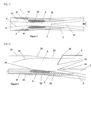
Fig. 2 ] shows schematic illustrations of the respective levels of the different surfaces of the nose and one of the wing rails in an example of the railway frog of the invention according to a side way of the frog with respect to a top view, - [
Fig. 3 ] shows a schematic illustration of the respective position of two different wheel profiles with respect to the different upper surface portions of an example of the railway frog of the invention at different steps of the traveling of the wheels in the railway frog and according to a plane in section essentially perpendicular to the main traveling axis of the wheels. - It is reminded that the wheel only impacts the
nose 3 of the railway frog 1 when the wheels passing through the railway frogs 1 arrive at one of the upstream ends of thewing rails 2, roll from this end to thenose 3 side of the frog 1 to reach one of the downstream ends of thenose 3 and leave the frog 1. - According to a classical arrangement, the flangeways 4 crossing inside the railway frog 1 are mainly linear in a horizontal plan in section. However, alternative usual arrangements exist wherein at least one of the flangeways 4 is curved. Despite crossed together, the flangeways 4 define the main axis of the railway frog 1. According to a particular interpretation of the arrangement of the railway frog 1, such main axis might be considered as a symmetrical axis of the railway frog 1 as further detailed.
- The present invention concerns a railway frog 1 having two
wing rails 2 positioned on both sides of anose 3, thewing rails 2 being separated with respect to thenose 3 by respective crossing flangeways 4, characterized in that, according to a plane in section essentially perpendicular to the axis of flangeways 4, the plane in section being positioned in the area of thenose 3, the upper rolling surface of at least one of thewing rails 2 is higher than the upper surface of thetip 31 of thenose 3 and lower than the upper surface of theend 32 of thenose 3 topping, this upper rolling surface of thewing rail 2 corresponding to an area wherein the rolling wheel is transferred from thewing rail 2 to thenose 3 of the frog 1. - Such construction of the upper surfaces of the different parts of the railway frog 1 of the invention is arranged in order to operate a transfer of the wheel from the
wing rail 2 to thenose 3 by minimizing the abrupt change of the position of the wheel in height by the upper surface of thewing rail 3 and therefore minimize the force induced on thenose 3. Thus, the transfer of the wheel is operated while the wheel is rolling at constant height along a portion of the upper surface of thewing rail 2. While the wheel tread portion the furthest of the flange of the wheel is traveling on thewing rail 2, theramp 23 formed by the progressive increase in height of the front surface of thenose 3 between thetip 31 of thenose 3 and theend 32 of thenose 3 topping is arranged to progressively come in contact against the wheel tread portion the closest to the flange of the wheel in order to bear the wheel. As the upper rolling surface of thewing rails 2 is higher than the upper surface of thetip 31 of thenose 3 and lower than the upper surface of theend 32 of thenose 3 topping, thenose 3 is progressively positioned against the wheel tread portion wherein, depending on the wheel profile, a concave curvature might be present, no matter if a concavity exists or how wide is the concavity. The increase of the height of thenose 3 between itstip 31 and theend 32 of thenose 3 topping to position the upper surface of thenose 3 higher than the upper surface of thewing rail 2 bearing the wheel by the wheel tread portion the furthest of its flange, progressively provides a support to bear the wheel travelling through the railway frog 1. - According to an example relating to a variant of the invention, the railway frog 1 is characterized in that the upper rolling surface of at least one of the
wing rails 2 comprises at least twosurface portions upstream edge 6 of the railway frog 1, the rolling surface of thewing rail 2 is arranged to match with the rolling surface of an upstream connected rail. For example, according to a plane in section essentially perpendicular to the axis of flangeways 4 of the railway frog 1, such match is reached when the respective upper rolling surfaces of thewing rails 2 and the connected rail have identical shapes. The at least twosurface portions wing rail 2 having different respective heights are arranged to realize, on its upstream side, an optimized connection with upstream rails and, on its downstream side, a rolling surface to bear and position the wheel in order to realize a smooth transfer of this wheel on thenose 3. The respective height of eachsurface portion wing rail 2 is adapted to its respective purpose on each end of the railway frog 1. According to a preferred arrangement, thewing rail 2 comprises an intermediate arrangement between these twoportions wing rail 2 against the wheel tread. Indeed, on its upstream end on theupstream edge 6 of the railway frog 1, thefirst surface portion 21 of the rolling surface of thewing rail 2 is similar to the rolling surface of a rail profile so that thisfirst surface portion 21 of thewing rail 2 is in contact with the wheel tread portion the closest to its flange to bear the rolling wheel. On the contrary, on the downstream end of thesecond surface portion 22 of thewing rail 2, thesecond surface portion 22 of the rolling surface of thewing rail 2 bears the rolling wheel by being in contact with the wheel tread portion the furthest of the flange of the wheel in order to avoid the interference by the eventual concavity of the wheel profile, so that the position of the wheel in height is independent of the profile of the wheel. - According to an example relating to a particular variant of the invention, the railway frog 1 is characterized in that the maximum height difference between the upper rolling surface of the
wing rail 2 and the upper surface of thenose 3 is in a range of 0 and 10 millimeters. According to a prefer arrangement of the height difference is in a range of 0 and 8 millimeters, ideally in a range of 1 and 6 millimeters. - According to an example relating to another variant of the invention, the railway frog 1 is characterized in that the two
surface portions wing rail 2 are arranged along theedge 5 of thewing rail 2 with the flangeways 4 so that thefirst surface portion 21 positioned upstream is higher and thesecond surface portion 22 positioned downstream is lower, at least the positioneddownstream surface portion 22 corresponding to an area of thewing rail 2 wherein the rolling wheel is transferred from thewing rail 2 to thenose 3 of the frog 1. Thus, thewing rail 2 comprisesportions wing rail 2. According to an example corresponding to a preferred arrangement, the upper surface of theupstream portion 21 of thewing rail 2 is positioned at the same level as the upper surface of theend 32 of thenose 3 topping. Additionally, the upper surface of thedownstream portion 22 of thewing rail 2 is positioned at a lower level than the upper surface of theend 32 of thenose 3 topping. According to an example corresponding to another preferred arrangement, theedge 5 of thewing rail 2 with the flangeways 4 shows anangle 51 in a horizontal plan in section due to the two flangeways 4 crossing inside the frog 1, so that the upstream portion of theedge 5 with respect to theangle 51 is positioned along the first flangeway 4 defining the main traveling direction of the wheel rolling on thewing rail 2 of the frog 1 while the portion of theedge 5 downstream with respect to theangle 51 is positioned along the second flangeway 4 over which the rolling wheel is intended to pass thanks to the frog 1, this second flangeway 4 being positioned between thewing rail 2 and thenose 3. Each of the twosurface portions edge 5 of thewing rail 2 positioned on different sides of theangle 51, so that theupstream portion 21 of thewing rail 2 is mainly positioned upstream with respect to theangle 51 of theedge 5, while thedownstream portion 22 of thewing rail 2 is mainly positioned downstream with respect to theangle 51 of theedge 5. Further, because of thisangle 51 of theedge 5 of thewing rail 2 with respect to the first flangeway 4 defining the main traveling direction of the wheel rolling on thewing rail 2 of the frog 1, thedownstream portion 22 of thewing rail 2 is laterally offset from this first flangeway 4. However, as the rolling wheel keeps its main traveling direction considered without swaying, the upper surface of thewing rail 2 bearing the wheel by contact with the wheel tread, is moved laterally from the wheel tread portion the closest to its flange to the wheel tread portion the furthest of its flange. Consequently, because of thisangle 51 of theedge 5 of thewing rail 2, the upper surface of thewing rail 2 becomes in contact with the wheel tread portion which might be concerned by the wear of the wheel. - According to an additional example corresponding to a particular arrangement of these two
portions wing rail 2, theseportions - According to an additional example corresponding to a an alternative to the previous particular arrangement,
downstream portion 22 of thewing rail 2 may have a concave or convex curved surface. - According to an example relating to another variant of the invention, the railway frog 1 is characterized in that the upper rolling surface comprises a
ramp 23 to achieve a continuity of the rolling surface of thewing rail 2 between the different respective heights of the twosurface portions ramp 23, thisramp 23 is positioned along theedge 5 of thewing rail 2 with the flangeways 4 between the higherupstream portion 21 and the lowerdownstream portion 22. According to an example corresponding to a particular arrangement of theramp 23, thisramp 23 is positioned downstream with respect to theangle 51 of theedge 5 of thewing rail 2. Depending on the profile requested, thisramp 23 may be realized according to different arrangement in a vertical plan in section comprising the main axis of the rolling surface of theupstream portion 21 of thewing rail 2, this main axis being essentially parallel to theedge 5 of thewing rail 2 with flangeways and more particularly with the first flangeway 4. According to a preferred arrangement, according to a plane in section essentially parallel to theedge 5 of thewing rail 2 with the first flangeway 4, theramp 23 has a linear arrangement and shows an angle with respect to a horizontal plan. However, alternative arrangements may be considered. For example, theramp 23 may have a curvature showing a convexity or a concavity. Additionally, this curvature may be realized by a broken arch formed by a succession of linear portions. Further, theramp 23 between the upstream and the downstream surface portions of thewing rail 2 might be formed by successive horizontal steps. - According to an example relating to another variant of the invention, the railway frog 1 is characterized in that the most downstream point of the
ramp 23 is positioned upstream from the area of thewing rail 2 wherein the rolling wheel is transferred from thewing rail 2 to thenose 3 of the frog 1. According to such example of construction, the upstream end of thelower surface portion 22 along theedge 5 of thewing rail 2 is positioned upstream to thenose 3 of the frog 1 and more particularly upstream to thetip 31 of thenose 3. Thus, according to such construction, the wheel traveling on the upper surface of thewing rail 2 leaves theramp 23 and reaches thelower surface portions 22 of thewing rail 2 previously its transfer from thewing rail 2 to thenose 3 above the flangeway positioned between thewing rail 2 and thenose 3. Consequently, the lowering of the wheel along theramp 23 is finished when the wheel travels on thelower surface portions 22 of thewing rail 2, so that the wheel travels at the adapted height on thewing rail 2 to be transferred to the upper surface of thenose 3. - According to an example relating to another variant of the invention, the railway frog 1 is characterized in that the
ramp 23 being positioned in the extension of thesurface portion 21 of thewing rail 2 having the highest height, has a larger width positioned upstream and a narrower width positioned downstream. According to a top view of the construction of thewing rail 2, by being positioned in the extension of thehigher surface portion 21 of thewing rail 2 what means in the extension of the main traveling direction of the wheel rolling on thewing rail 2 of the frog 1, theramp 23 positioned downstream with respect to theangle 51 of theedge 5, is arranged according to an extension of thehigher surface portion 21 of thewing rail 2 positioned upstream with respect to theangle 51. Consequently, theramp 23 is arranged to bear the rolling wheel according to a contact against the wheel tread similarly to the contact of thehigher surface portion 21 against the wheel. Theramp 23 and thehigher surface portion 21 of thewing rail 2 are both arranged to interact with the wheel tread portion the closest to the flange of the wheel. According to a top view of the construction of thewing rail 2, because of theangle 51 of theedge 5 of thewing rail 2, theedge 5 of thewing rail 2 downstream thisangle 51 shows theedge 5 inclined with respect to the main traveling direction of the rolling wheel. Consequently, as theramp 23 is in the extension of thehigher surface portion 21, theinclined edge 5 provides a reduction in the width of theramp 23. Such reduction in the width of theramp 23 participates to the disappearance of theramp 23 upstream from the area of thewing rail 2 wherein the rolling wheel is transferred from thewing rail 2 to thenose 3 of the frog 1. - According to an example relating to another variant of the invention, the railway frog 1 is characterized in that, according to a plane in section essentially perpendicular to the axis of flangeways 4, the
ramp 23 is positioned between theedge 5 of thewing rail 2 with the flangeway 4 and at least a part of thesurface portion 22 of thewing rail 2 having the lowest height. More particularly, theramp 23 is positioned between theedge 5 of thewing rail 2 with the second flangeway 4 over which the rolling wheel is intended to pass and a part of thesurface portion 22 of thewing rail 2 having the lowest height. Thus, upstream to the most downstream point of theramp 23, thelower surface portion 22 of the upper surface of thewing rail 2 is arranged along the lateral edge of theramp 23 on the opposite side the flangeways 4. Such construction of this variant of the invention provides an arrangement wherein, while the wheel travels on theramp 23 by its wheel tread portion the closest to its flange, the wheel tread portion the furthest of its flange is able to interact with thelower surface portion 22 of thewing rail 2 upstream to the most downstream point of theramp 23, so that the wheel becomes bear by thislower surface portion 22 of thewing rail 2. Depending on the wear of the profile or the type of the wheel, the concavity of the curvature may be more or less deep, so that the rotating axis of the wheel rolling on theramp 23 is more or less high with respect to bottom surface of the frog 1 or with respect to thelower surface portion 22 of thewing rail 2. Consequently, because of thelower surface portion 22 of the upper surface of thewing rail 2 is arranged along the lateral edge of theramp 23, the wheel tread portion the furthest of its flange interacts with thelower surface portion 22 of thewing rail 2 around a point positioned upstream with respect to the most downstream point of theramp 23. Thus, depending on the type of the profile of the wheel due to its eventual wear, the transfer of the wheel from theramp 23 to thelower surface portion 22 of thewing rail 2 may be operated at different positions along theramp 23, so that the bearing contact of the upper surface of thewing rail 2 with the wheel tread is moved laterally from the wheel tread portion the closest to its flange borne by theramp 23 to the wheel tread portion the furthest of its flange borne by thelower surface portion 22 of thewing rail 2. - According to an example relating to another variant of the invention, the railway frog 1 is characterized in that the
wing rail 2 comprises anadditional ramp 24 arranged upstream and in the extension of thesurface portion 22 of thewing rail 2 having the lowest height and positioned along the lateral edge of theramp 23 and/or along thehighest surface portion 21 of thewing rail 2 on the opposite side the flangeways 4. Thisadditional ramp 24 is arranged so that its highest end correspond to its downstream end in the extension of thelowest surface portion 22 of thewing rail 2. The height of theadditional ramp 24 increases from its upstream end to its downstream end. - Thus, according to such construction, while the wheel travels on the
upper surface 21 or on theramp 23 of thewing rail 2 by its wheel tread portion the closest to its flange, the wheel tread portion the furthest of its flange might be able to interact with theadditional ramp 24 in the extension and upstream thelower surface portion 22 of thewing rail 2, so that the wheel might become bear by the upper surface of thisadditional ramp 24. Depending on the wear of the profile or the type of the wheel, the concavity of the curvature may be more or less deep, so that the rotating axis of the wheel rolling on theupper surface 21 or on theramp 23 is more or less high with respect to bottom surface of the frog. Consequently, because of theadditional ramp 24 increasing in the extension and upstream thelower surface portion 22 of the upper surface of thewing rail 2 is arranged along the lateral edge of theupper surface 21 or of theramp 23, the wheel tread portion the furthest of its flange might interact with the upper surface of theadditional ramp 24 around a point positioned upstream with respect to the most upstream point of thelower surface portion 22 of thewing rail 2 and even around a point positioned upstream with respect to the most upstream point of theramp 23. Thus, depending on the type of the profile of the wheel due to its eventual wear, the transfer of the wheel from theupper surface portion 21 to thelower surface portion 22 of thewing rail 2 might be operated at different positions along theupper surface portion 21 or along theramp 23, so that the bearing contact of the upper surface of thewing rail 2 with the wheel tread is moved laterally from the wheel tread portion the closest to its flange borne by theupper surface portion 21 of thewing rail 2 or by theramp 23 to the wheel tread portion the furthest of its flange borne by the upper surface of thisadditional ramp 24. - According to a preferred arrangement, according to a plane in section essentially parallel to the
edge 5 of thewing rail 2 with the first flangeway 4, thisramp 24 has a linear arrangement and shows an angle with respect to a horizontal plan. However, alternative arrangements may be considered. For example, theramp 24 may have a curvature showing a convexity or a concavity. Additionally, this curvature may be realized by a broken arch formed by a succession of linear portions. Further, theramp 24 between the upstream and the downstream surface portions of thewing rail 2 might be formed by successive horizontal steps. - According to an example relating to another variant of the invention, the railway frog 1 is characterized in that the railway frog 1 has a symmetrical arrangement according to an axis passing by the intersection of the crossing flangeways 4 in the frog 1. However, since the two traveling directions of the wheels in the frog 1 are mainly defined by the crossing flangeways 4 and the edges of the wing rails 2 and since these crossing flangeways 4 and edges of the wing rails 2 may be linear or curved or a combination thereof, the "symmetrical arrangement" feature must be understood according to a large interpretation wherein the symmetry of the frog mainly or only concerns the distribution of the different functional parts of the frog 1 of the invention on both side of the main axis passing by the intersection of the crossing flangeways 4 in the frog 1.
- According to an example relating to another variant of the invention, the railway frog 1 is characterized in that the upper rolling
surface portions ramp 23, of at least onewing rail 2 of the frog 1 are made by respective different materials and/or supported by respective different blocks assembled to make at least a part of thewing rail 2. According to such example, the railway frog 1 of the invention may be realized by the connection of several structural elements, eventually made by respective materials with different hardness, and assembled and maintained together in order to form one or several parts of the railway frog 1 such as itsnose 3 or its wing rails 2. - Of course, the invention is not limited to the at least one embodiment described and represented in the accompanying drawings. Modifications remain possible, particularly from the viewpoint of the composition of the various elements or by substitution of technical equivalents without thereby exceeding the field of protection of the invention.
Claims (12)
- A railway frog (1) having two wing rails (2) positioned on both sides of a nose (3), the wing rails (2) being separated with respect to the nose (3) by respective crossing flangeways (4), characterized in that, according to a plane in section essentially perpendicular to the axis of flangeways (4), the plane in section being positioned in the area of the nose (3), the upper rolling surface of at least one of the wing rails (2) is higher than the upper surface of the tip (31) of the nose (3) and lower than the upper surface of the end (32) of the nose (3) topping, this upper rolling surface of the wing rail (2) corresponding to an area wherein the rolling wheel is transferred from the wing rail (2) to the nose (3) of the frog (1).
- A railway frog (1) according to claim 1, characterized in that the upper rolling surface of at least one of the wing rails (2) comprises at least two surface portions (21, 22) having different respective heights with respect to the bottom surface of the railway frog (1).
- A railway frog (1) according to claim 2, characterized in that the two surface portions (21, 22) of the upper rolling surface of the wing rail (2) are arranged along the edge (5) of the wing rail (2) with the flangeways (4) so that the first surface portion (21) positioned upstream is higher and the second surface portion (22) positioned downstream is lower, at least the positioned downstream surface portion (22) corresponding to an area of the wing rail (2) wherein the rolling wheel is transferred from the wing rail (2) to the nose (3) of the frog (1).
- A railway frog (1) according to claims 2 or 3, characterized in that the upper rolling surface comprises a ramp (23) to achieve a continuity of the rolling surface of the wing rail (2) between the different respective heights of the two surface portions (21, 22) having different heights.
- A railway frog (1) according to at least claim 4, characterized in that the most downstream point of the ramp (23) is positioned upstream from the area of the wing rail (2) wherein the rolling wheel is transferred from the wing rail (2) to the nose (3) of the frog (1).
- A railway frog (1) according to claims 4 or 5, characterized in that, according to a plane in section essentially parallel to the edge (5) of the wing rail (2) with the flangeway (4), the ramp (23) has a linear arrangement.
- A railway frog (1) according to claims 4 to 6, characterized in that the ramp (23) being positioned in the extension of the surface portion (21) of the wing rail (2) having the highest height, has a larger width positioned upstream and a narrower width positioned downstream.
- A railway frog (1) according to claims 4 to 7, characterized in that, according to a plane in section essentially perpendicular to the axis of flangeways (4), the ramp (23) is positioned between the edge (5) of the wing rail (2) with the flangeway (4) and at least a part of the surface portion (22) of the wing rail (2) having the lowest height.
- A railway frog (1) according to any previous claims, characterized in that the height difference between the upper rolling surface of the wing rail (2) and the upper surface of the nose (3) is in a range between 0 and 10 millimeters.
- A railway frog (1) according to any previous claims, characterized in that, according to a plane in section essentially perpendicular to the axis of flangeways (4), the upstream edge (6) formed by the rolling surface of the wing rails (2) is shaped to match with the rolling surface of an upstream connected rail.
- A railway frog (1) according to any previous claims, characterized in that the railway frog (1) has a symmetrical arrangement according to an axis passing by the intersection of the crossing flangeways (4) in the frog (1).
- A railway frog (1) according to any previous claims, characterized in that the upper rolling surface portions (21, 22), eventually including a ramp (23), of at least one wing rail (2) of the frog (1) are made by respective different materials and/or supported by respective different blocks assembled to make at least a part of the wing rail (2).
Priority Applications (4)
| Application Number | Priority Date | Filing Date | Title |
|---|---|---|---|
| PL22315158.0T PL4310251T3 (en) | 2022-07-19 | 2022-07-19 | Railway frog adapted to several wheel profiles |
| EP22315158.0A EP4310251B1 (en) | 2022-07-19 | 2022-07-19 | Railway frog adapted to several wheel profiles |
| ES22315158T ES3029683T3 (en) | 2022-07-19 | 2022-07-19 | Railway frog adapted to several wheel profiles |
| IL304297A IL304297A (en) | 2022-07-19 | 2023-07-06 | Railway frog adapted to several wheel profiles |
Applications Claiming Priority (1)
| Application Number | Priority Date | Filing Date | Title |
|---|---|---|---|
| EP22315158.0A EP4310251B1 (en) | 2022-07-19 | 2022-07-19 | Railway frog adapted to several wheel profiles |
Publications (3)
| Publication Number | Publication Date |
|---|---|
| EP4310251A1 EP4310251A1 (en) | 2024-01-24 |
| EP4310251B1 true EP4310251B1 (en) | 2025-02-12 |
| EP4310251C0 EP4310251C0 (en) | 2025-02-12 |
Family
ID=82850793
Family Applications (1)
| Application Number | Title | Priority Date | Filing Date |
|---|---|---|---|
| EP22315158.0A Active EP4310251B1 (en) | 2022-07-19 | 2022-07-19 | Railway frog adapted to several wheel profiles |
Country Status (4)
| Country | Link |
|---|---|
| EP (1) | EP4310251B1 (en) |
| ES (1) | ES3029683T3 (en) |
| IL (1) | IL304297A (en) |
| PL (1) | PL4310251T3 (en) |
Citations (8)
| Publication number | Priority date | Publication date | Assignee | Title |
|---|---|---|---|---|
| DE1271739B (en) | 1966-03-12 | 1968-07-04 | Kloeckner Werke Ag | Heart |
| CA2085285C (en) | 1991-12-13 | 2003-06-24 | Stephen R. Kuhn | Railroad frog |
| US6732980B2 (en) | 2002-10-08 | 2004-05-11 | Progress Rail Services Corp. | Railway frog wear component |
| DE102004017746A1 (en) | 2004-04-06 | 2005-11-03 | Witt Industrie Elektronik Gmbh | Method and device for detecting the condition and for processing turnouts in track systems |
| EP1873309B1 (en) | 2006-06-30 | 2010-08-18 | DB Netz AG | Protective ramp of a wing rail in points |
| EP1873310B1 (en) | 2006-06-30 | 2011-05-04 | DB Netz AG | Cross frog |
| CN103696329B (en) | 2013-12-31 | 2015-08-19 | 中铁山桥集团有限公司 | A kind of fixed end frog wing rail |
| US20170233954A1 (en) | 2016-02-12 | 2017-08-17 | Holland, L.P. | Robotically-Controlled Laser Cladding Process for Repair of Worn and/or Damaged Railway Structures |
Family Cites Families (2)
| Publication number | Priority date | Publication date | Assignee | Title |
|---|---|---|---|---|
| US5531409A (en) * | 1995-02-21 | 1996-07-02 | Willow; Robert E. | Flange bearing bolted rail frog for railroad turnouts and crossings |
| CN104975542A (en) * | 2015-01-13 | 2015-10-14 | 中铁宝桥集团有限公司 | Fixed frog wheel transmission area wing rail buffering structure |
-
2022
- 2022-07-19 PL PL22315158.0T patent/PL4310251T3/en unknown
- 2022-07-19 EP EP22315158.0A patent/EP4310251B1/en active Active
- 2022-07-19 ES ES22315158T patent/ES3029683T3/en active Active
-
2023
- 2023-07-06 IL IL304297A patent/IL304297A/en unknown
Patent Citations (8)
| Publication number | Priority date | Publication date | Assignee | Title |
|---|---|---|---|---|
| DE1271739B (en) | 1966-03-12 | 1968-07-04 | Kloeckner Werke Ag | Heart |
| CA2085285C (en) | 1991-12-13 | 2003-06-24 | Stephen R. Kuhn | Railroad frog |
| US6732980B2 (en) | 2002-10-08 | 2004-05-11 | Progress Rail Services Corp. | Railway frog wear component |
| DE102004017746A1 (en) | 2004-04-06 | 2005-11-03 | Witt Industrie Elektronik Gmbh | Method and device for detecting the condition and for processing turnouts in track systems |
| EP1873309B1 (en) | 2006-06-30 | 2010-08-18 | DB Netz AG | Protective ramp of a wing rail in points |
| EP1873310B1 (en) | 2006-06-30 | 2011-05-04 | DB Netz AG | Cross frog |
| CN103696329B (en) | 2013-12-31 | 2015-08-19 | 中铁山桥集团有限公司 | A kind of fixed end frog wing rail |
| US20170233954A1 (en) | 2016-02-12 | 2017-08-17 | Holland, L.P. | Robotically-Controlled Laser Cladding Process for Repair of Worn and/or Damaged Railway Structures |
Non-Patent Citations (8)
| Title |
|---|
| ANONYMOUS: "Why are S&C layouts failing?", RTM, 17 May 2017 (2017-05-17), XP093338060, Retrieved from the Internet <URL:https://www.railtechnologymagazine.com/Comment/why-are-sc-layouts-failing> |
| BEZIN YANN, PåLSSON BJöRN A.: "Multibody simulation benchmark for dynamic vehicle-track interaction in switches and crossings: modelling description and simulation tasks", VEHICLE SYSTEM DYNAMICS: INTERNATIONAL JOURNAL OF VEHICLE MECHANICS AND MOBILITY, TAYLOR & FRANCIS, GB, vol. 61, no. 3, 4 March 2023 (2023-03-04), GB , pages 644 - 659, XP093338062, ISSN: 0042-3114, DOI: 10.1080/00423114.2021.1942079 |
| D11 - Affidavit Dr Andreas Zoll |
| D1A - EISENBAHNWESEN-SEMINAR (ANNOUNCEMENT) 04.04.2022 |
| D1b - Eisenbahnwesen-Seminar (announcement) Sommersemester 2022 |
| OÃBERGER UWE, KOLLMENT WERNER, ECK SVEN: "Insights towards Condition Monitoring of Fixed Railway Crossings", PROCEDIA STRUCTURAL INTEGRITY, vol. 4, 1 January 2017 (2017-01-01), pages 106 - 114, XP093338058, ISSN: 2452-3216, DOI: 10.1016/j.prostr.2017.07.007 |
| WAN C., MARKINE V. L.: "Parametric study of wheel transitions at railway crossings", VEHICLE SYSTEM DYNAMICS: INTERNATIONAL JOURNAL OF VEHICLE MECHANICS AND MOBILITY, TAYLOR & FRANCIS, GB, vol. 53, no. 12, 2 December 2015 (2015-12-02), GB , pages 1876 - 1901, XP093338055, ISSN: 0042-3114, DOI: 10.1080/00423114.2015.1089358 |
| ZOLL. A.: "Belastung und Belastbarkeit von Weichenherzstücken - Zusammenhänge und Problemlösungen", EISENBAHNWESEN-SEMINAR; 04. JULI 2022, DB SYSTEMTECHNIK, DE, 7 April 2022 (2022-04-07) - 2022-04-07, DE, pages 1 - 25, XP009556158 |
Also Published As
| Publication number | Publication date |
|---|---|
| IL304297A (en) | 2024-02-01 |
| ES3029683T3 (en) | 2025-06-25 |
| EP4310251C0 (en) | 2025-02-12 |
| PL4310251T3 (en) | 2025-07-14 |
| EP4310251A1 (en) | 2024-01-24 |
Similar Documents
| Publication | Publication Date | Title |
|---|---|---|
| US8424812B1 (en) | Elevated frog and rail track assembly | |
| US5527127A (en) | Traffic barrier for guidance installations | |
| CN101428727A (en) | Moving walkway | |
| EP4310251B1 (en) | Railway frog adapted to several wheel profiles | |
| EP0040533B1 (en) | Railway turnouts | |
| US5531409A (en) | Flange bearing bolted rail frog for railroad turnouts and crossings | |
| US4015805A (en) | Railway switch or railway crossing | |
| US4469299A (en) | Railway turnouts | |
| US9453307B2 (en) | Rail switch having a main track and a branch track | |
| CN216739067U (en) | Cross crossover turnout for tramcar and light rail line | |
| JP3838913B2 (en) | Crossing frog | |
| EP1873309B1 (en) | Protective ramp of a wing rail in points | |
| CN116279671A (en) | A method for reducing the risk of vehicle derailment at the turnout guard rail position | |
| EP1183424B1 (en) | Forked railway track system | |
| JP2017529469A (en) | Overhead guided transport track span and viaduct formed by such span | |
| RU2342479C1 (en) | Groove rail | |
| JP3153583U (en) | Nose movable crossing structure | |
| RU223655U1 (en) | Turnout cross with continuous rolling surface | |
| RU2668146C1 (en) | Cross-tie for the curved part of the track | |
| CA3104039C (en) | Stock rail | |
| KR20100098149A (en) | Arrangement for controlled-guiding a wheel set | |
| JP4099613B2 (en) | Rail wear measuring ruler and method of construction of rail joint structure using the same | |
| US896985A (en) | Railway-rail. | |
| KR102038753B1 (en) | Y-type driving track of monorail | |
| RU61295U1 (en) | DEVICE FOR MAKING SAFETY OF MOTION AND REDUCING THE LATERAL WEAR OF RAILS IN CURVES |
Legal Events
| Date | Code | Title | Description |
|---|---|---|---|
| PUAI | Public reference made under article 153(3) epc to a published international application that has entered the european phase |
Free format text: ORIGINAL CODE: 0009012 |
|
| STAA | Information on the status of an ep patent application or granted ep patent |
Free format text: STATUS: THE APPLICATION HAS BEEN PUBLISHED |
|
| AK | Designated contracting states |
Kind code of ref document: A1 Designated state(s): AL AT BE BG CH CY CZ DE DK EE ES FI FR GB GR HR HU IE IS IT LI LT LU LV MC MK MT NL NO PL PT RO RS SE SI SK SM TR |
|
| STAA | Information on the status of an ep patent application or granted ep patent |
Free format text: STATUS: REQUEST FOR EXAMINATION WAS MADE |
|
| 17P | Request for examination filed |
Effective date: 20240529 |
|
| RAV | Requested validation state of the european patent: fee paid |
Extension state: MA Effective date: 20240529 |
|
| RBV | Designated contracting states (corrected) |
Designated state(s): AL AT BE BG CH CY CZ DE DK EE ES FI FR GB GR HR HU IE IS IT LI LT LU LV MC MK MT NL NO PL PT RO RS SE SI SK SM TR |
|
| RIC1 | Information provided on ipc code assigned before grant |
Ipc: E01B 7/10 20060101AFI20240722BHEP |
|
| GRAP | Despatch of communication of intention to grant a patent |
Free format text: ORIGINAL CODE: EPIDOSNIGR1 |
|
| STAA | Information on the status of an ep patent application or granted ep patent |
Free format text: STATUS: GRANT OF PATENT IS INTENDED |
|
| INTG | Intention to grant announced |
Effective date: 20240906 |
|
| GRAS | Grant fee paid |
Free format text: ORIGINAL CODE: EPIDOSNIGR3 |
|
| GRAA | (expected) grant |
Free format text: ORIGINAL CODE: 0009210 |
|
| STAA | Information on the status of an ep patent application or granted ep patent |
Free format text: STATUS: THE PATENT HAS BEEN GRANTED |
|
| AK | Designated contracting states |
Kind code of ref document: B1 Designated state(s): AL AT BE BG CH CY CZ DE DK EE ES FI FR GB GR HR HU IE IS IT LI LT LU LV MC MK MT NL NO PL PT RO RS SE SI SK SM TR |
|
| REG | Reference to a national code |
Ref country code: GB Ref legal event code: FG4D |
|
| REG | Reference to a national code |
Ref country code: CH Ref legal event code: EP |
|
| REG | Reference to a national code |
Ref country code: DE Ref legal event code: R096 Ref document number: 602022010489 Country of ref document: DE |
|
| REG | Reference to a national code |
Ref country code: IE Ref legal event code: FG4D |
|
| U01 | Request for unitary effect filed |
Effective date: 20250307 |
|
| U07 | Unitary effect registered |
Designated state(s): AT BE BG DE DK EE FI FR IT LT LU LV MT NL PT RO SE SI Effective date: 20250314 |
|
| REG | Reference to a national code |
Ref country code: ES Ref legal event code: FG2A Ref document number: 3029683 Country of ref document: ES Kind code of ref document: T3 Effective date: 20250625 |
|
| PG25 | Lapsed in a contracting state [announced via postgrant information from national office to epo] |
Ref country code: RS Free format text: LAPSE BECAUSE OF FAILURE TO SUBMIT A TRANSLATION OF THE DESCRIPTION OR TO PAY THE FEE WITHIN THE PRESCRIBED TIME-LIMIT Effective date: 20250512 |
|
| PG25 | Lapsed in a contracting state [announced via postgrant information from national office to epo] |
Ref country code: IS Free format text: LAPSE BECAUSE OF FAILURE TO SUBMIT A TRANSLATION OF THE DESCRIPTION OR TO PAY THE FEE WITHIN THE PRESCRIBED TIME-LIMIT Effective date: 20250612 |
|
| PG25 | Lapsed in a contracting state [announced via postgrant information from national office to epo] |
Ref country code: HR Free format text: LAPSE BECAUSE OF FAILURE TO SUBMIT A TRANSLATION OF THE DESCRIPTION OR TO PAY THE FEE WITHIN THE PRESCRIBED TIME-LIMIT Effective date: 20250212 |
|
| PG25 | Lapsed in a contracting state [announced via postgrant information from national office to epo] |
Ref country code: GR Free format text: LAPSE BECAUSE OF FAILURE TO SUBMIT A TRANSLATION OF THE DESCRIPTION OR TO PAY THE FEE WITHIN THE PRESCRIBED TIME-LIMIT Effective date: 20250513 |
|
| U20 | Renewal fee for the european patent with unitary effect paid |
Year of fee payment: 4 Effective date: 20250728 |
|
| PG25 | Lapsed in a contracting state [announced via postgrant information from national office to epo] |
Ref country code: SM Free format text: LAPSE BECAUSE OF FAILURE TO SUBMIT A TRANSLATION OF THE DESCRIPTION OR TO PAY THE FEE WITHIN THE PRESCRIBED TIME-LIMIT Effective date: 20250212 |
|
| PGFP | Annual fee paid to national office [announced via postgrant information from national office to epo] |
Ref country code: ES Payment date: 20250828 Year of fee payment: 4 |
|
| PGFP | Annual fee paid to national office [announced via postgrant information from national office to epo] |
Ref country code: NO Payment date: 20250801 Year of fee payment: 4 |
|
| PGFP | Annual fee paid to national office [announced via postgrant information from national office to epo] |
Ref country code: PL Payment date: 20250725 Year of fee payment: 4 |
|
| PGFP | Annual fee paid to national office [announced via postgrant information from national office to epo] |
Ref country code: CH Payment date: 20250813 Year of fee payment: 4 |
|
| PG25 | Lapsed in a contracting state [announced via postgrant information from national office to epo] |
Ref country code: CZ Free format text: LAPSE BECAUSE OF FAILURE TO SUBMIT A TRANSLATION OF THE DESCRIPTION OR TO PAY THE FEE WITHIN THE PRESCRIBED TIME-LIMIT Effective date: 20250212 |
|
| PG25 | Lapsed in a contracting state [announced via postgrant information from national office to epo] |
Ref country code: SK Free format text: LAPSE BECAUSE OF FAILURE TO SUBMIT A TRANSLATION OF THE DESCRIPTION OR TO PAY THE FEE WITHIN THE PRESCRIBED TIME-LIMIT Effective date: 20250212 |
|
| RAP4 | Party data changed (patent owner data changed or rights of a patent transferred) |
Owner name: VOSSLOH SWITCH SYSTEMS FRANCE |
|
| U1H | Name or address of the proprietor changed after the registration of the unitary effect |
Owner name: VOSSLOH SWITCH SYSTEMS FRANCE; FR |
|
| PLBI | Opposition filed |
Free format text: ORIGINAL CODE: 0009260 |
|
| PLAX | Notice of opposition and request to file observation + time limit sent |
Free format text: ORIGINAL CODE: EPIDOSNOBS2 |