EP4310238A1 - Clothes treatment device - Google Patents
Clothes treatment device Download PDFInfo
- Publication number
- EP4310238A1 EP4310238A1 EP21936530.1A EP21936530A EP4310238A1 EP 4310238 A1 EP4310238 A1 EP 4310238A1 EP 21936530 A EP21936530 A EP 21936530A EP 4310238 A1 EP4310238 A1 EP 4310238A1
- Authority
- EP
- European Patent Office
- Prior art keywords
- water
- water supply
- outer tub
- treatment device
- clothes treatment
- Prior art date
- Legal status (The legal status is an assumption and is not a legal conclusion. Google has not performed a legal analysis and makes no representation as to the accuracy of the status listed.)
- Pending
Links
Images




Classifications
-
- D—TEXTILES; PAPER
- D06—TREATMENT OF TEXTILES OR THE LIKE; LAUNDERING; FLEXIBLE MATERIALS NOT OTHERWISE PROVIDED FOR
- D06F—LAUNDERING, DRYING, IRONING, PRESSING OR FOLDING TEXTILE ARTICLES
- D06F25/00—Washing machines with receptacles, e.g. perforated, having a rotary movement, e.g. oscillatory movement, the receptacle serving both for washing and for centrifugally separating water from the laundry and having further drying means, e.g. using hot air
-
- D—TEXTILES; PAPER
- D06—TREATMENT OF TEXTILES OR THE LIKE; LAUNDERING; FLEXIBLE MATERIALS NOT OTHERWISE PROVIDED FOR
- D06F—LAUNDERING, DRYING, IRONING, PRESSING OR FOLDING TEXTILE ARTICLES
- D06F33/00—Control of operations performed in washing machines or washer-dryers
- D06F33/50—Control of washer-dryers characterised by the purpose or target of the control
- D06F33/69—Control of cleaning or disinfection of washer-dryer parts, e.g. of tubs
-
- D—TEXTILES; PAPER
- D06—TREATMENT OF TEXTILES OR THE LIKE; LAUNDERING; FLEXIBLE MATERIALS NOT OTHERWISE PROVIDED FOR
- D06F—LAUNDERING, DRYING, IRONING, PRESSING OR FOLDING TEXTILE ARTICLES
- D06F34/00—Details of control systems for washing machines, washer-dryers or laundry dryers
- D06F34/04—Signal transfer or data transmission arrangements
-
- D—TEXTILES; PAPER
- D06—TREATMENT OF TEXTILES OR THE LIKE; LAUNDERING; FLEXIBLE MATERIALS NOT OTHERWISE PROVIDED FOR
- D06F—LAUNDERING, DRYING, IRONING, PRESSING OR FOLDING TEXTILE ARTICLES
- D06F34/00—Details of control systems for washing machines, washer-dryers or laundry dryers
- D06F34/14—Arrangements for detecting or measuring specific parameters
- D06F34/22—Condition of the washing liquid, e.g. turbidity
-
- D—TEXTILES; PAPER
- D06—TREATMENT OF TEXTILES OR THE LIKE; LAUNDERING; FLEXIBLE MATERIALS NOT OTHERWISE PROVIDED FOR
- D06F—LAUNDERING, DRYING, IRONING, PRESSING OR FOLDING TEXTILE ARTICLES
- D06F39/00—Details of washing machines not specific to a single type of machines covered by groups D06F9/00 - D06F27/00
- D06F39/08—Liquid supply or discharge arrangements
- D06F39/088—Liquid supply arrangements
-
- D—TEXTILES; PAPER
- D06—TREATMENT OF TEXTILES OR THE LIKE; LAUNDERING; FLEXIBLE MATERIALS NOT OTHERWISE PROVIDED FOR
- D06F—LAUNDERING, DRYING, IRONING, PRESSING OR FOLDING TEXTILE ARTICLES
- D06F39/00—Details of washing machines not specific to a single type of machines covered by groups D06F9/00 - D06F27/00
- D06F39/10—Filtering arrangements
-
- D—TEXTILES; PAPER
- D06—TREATMENT OF TEXTILES OR THE LIKE; LAUNDERING; FLEXIBLE MATERIALS NOT OTHERWISE PROVIDED FOR
- D06F—LAUNDERING, DRYING, IRONING, PRESSING OR FOLDING TEXTILE ARTICLES
- D06F2103/00—Parameters monitored or detected for the control of domestic laundry washing machines, washer-dryers or laundry dryers
- D06F2103/18—Washing liquid level
-
- D—TEXTILES; PAPER
- D06—TREATMENT OF TEXTILES OR THE LIKE; LAUNDERING; FLEXIBLE MATERIALS NOT OTHERWISE PROVIDED FOR
- D06F—LAUNDERING, DRYING, IRONING, PRESSING OR FOLDING TEXTILE ARTICLES
- D06F2105/00—Systems or parameters controlled or affected by the control systems of washing machines, washer-dryers or laundry dryers
- D06F2105/28—Electric heating
-
- D—TEXTILES; PAPER
- D06—TREATMENT OF TEXTILES OR THE LIKE; LAUNDERING; FLEXIBLE MATERIALS NOT OTHERWISE PROVIDED FOR
- D06F—LAUNDERING, DRYING, IRONING, PRESSING OR FOLDING TEXTILE ARTICLES
- D06F2105/00—Systems or parameters controlled or affected by the control systems of washing machines, washer-dryers or laundry dryers
- D06F2105/30—Blowers
-
- D—TEXTILES; PAPER
- D06—TREATMENT OF TEXTILES OR THE LIKE; LAUNDERING; FLEXIBLE MATERIALS NOT OTHERWISE PROVIDED FOR
- D06F—LAUNDERING, DRYING, IRONING, PRESSING OR FOLDING TEXTILE ARTICLES
- D06F2105/00—Systems or parameters controlled or affected by the control systems of washing machines, washer-dryers or laundry dryers
- D06F2105/46—Drum speed; Actuation of motors, e.g. starting or interrupting
-
- D—TEXTILES; PAPER
- D06—TREATMENT OF TEXTILES OR THE LIKE; LAUNDERING; FLEXIBLE MATERIALS NOT OTHERWISE PROVIDED FOR
- D06F—LAUNDERING, DRYING, IRONING, PRESSING OR FOLDING TEXTILE ARTICLES
- D06F39/00—Details of washing machines not specific to a single type of machines covered by groups D06F9/00 - D06F27/00
- D06F39/40—Steam generating arrangements
-
- D—TEXTILES; PAPER
- D06—TREATMENT OF TEXTILES OR THE LIKE; LAUNDERING; FLEXIBLE MATERIALS NOT OTHERWISE PROVIDED FOR
- D06F—LAUNDERING, DRYING, IRONING, PRESSING OR FOLDING TEXTILE ARTICLES
- D06F58/00—Domestic laundry dryers
- D06F58/20—General details of domestic laundry dryers
- D06F58/22—Lint collecting arrangements
-
- Y—GENERAL TAGGING OF NEW TECHNOLOGICAL DEVELOPMENTS; GENERAL TAGGING OF CROSS-SECTIONAL TECHNOLOGIES SPANNING OVER SEVERAL SECTIONS OF THE IPC; TECHNICAL SUBJECTS COVERED BY FORMER USPC CROSS-REFERENCE ART COLLECTIONS [XRACs] AND DIGESTS
- Y02—TECHNOLOGIES OR APPLICATIONS FOR MITIGATION OR ADAPTATION AGAINST CLIMATE CHANGE
- Y02B—CLIMATE CHANGE MITIGATION TECHNOLOGIES RELATED TO BUILDINGS, e.g. HOUSING, HOUSE APPLIANCES OR RELATED END-USER APPLICATIONS
- Y02B40/00—Technologies aiming at improving the efficiency of home appliances, e.g. induction cooking or efficient technologies for refrigerators, freezers or dish washers
Definitions
- the application relates to the technical field of clothes washing and care, and in particular to a clothes treatment device.
- a clothes treatment device equipped with a steam washing function adds an additional steam generator based on an ordinary clothes treatment device.
- High-temperature steam generated by the steam generator is introduced into a drum through pipes, and then sterilizes clothes inside an inner tub at high temperature.
- an additional steam generator needs to be added, which takes up space and increases cost.
- a separate first water supply pipeline and a water supply valve need to be provided, which further increases the cost of the device.
- embodiments of the application provide a clothes treatment device, which is intended to effectively reduce the cost of the device based on providing a steam washing function.
- An embodiment of the application provides a clothes treatment device, wherein the clothes treatment device includes a drum assembly, a first heating member, a first water supply pipeline, a connector, and a controller.
- the drum assembly includes an outer tub and an inner tub rotatably arranged in the outer tub, and a water storage area is provided in interior of the outer tub.
- the first heating member is arranged in the water storage area.
- a water supply valve is arranged on the first water supply pipeline.
- the connector is arranged on the outer tub, and is provided with a water supply structure configured to guide water in the first water supply pipeline to the interior of the outer tub.
- the controller is configured to control an operation state of the water supply valve based on a water level of the water storage area in a steam washing mode, so that the water storage area is within a set water level range, and control the first heating member to heat water in the water storage area within the set water level range, to generate steam.
- the clothes treatment device may further include a drying channel assembly.
- the connector further communicates the interior of the outer tub to an inlet of the drying channel assembly.
- At least a part of the steam enters the inner tub after sequentially passing through the connector and the drying channel assembly.
- the connector may be provided with a lint blocking structure configured to filter lint in the air, and water in the first water supply pipeline is also used to clean the lint blocking structure.
- the lint blocking structure may include a filter screen and/or ribs.
- the filter screen is arranged at a water outlet of the water supply structure, to prevent the lint from entering an inner cavity of the connector.
- the ribs are arranged in at least a part of area of the inner cavity of the connector, to adsorb the lint.
- the water supply structure may further include a spray structure.
- the spray structure is communicated with a water inlet of the water supply structure, is configured to form spray water in an inner cavity of the connector, and is provided with an outlet facing toward the lint blocking structure.
- the drying channel assembly may include a second heating member and a fan.
- the controller further controls operation of the fan and operation of the second heating member in the steam washing mode.
- the water supply structure may include a water inlet and a water outlet.
- the water inlet is opened on the connector, is located at an outer side of the outer tub, and is connected to the first water supply pipeline.
- the water outlet is opened on the connector, is located at an inner side of the outer tub, and is communicated with the inlet of the drying channel assembly.
- the outer tub is provided, at a position where the connector is mounted, with a penetration opening into which the water outlet extends.
- the penetration opening may be arranged on a rear side wall of the outer tub along an axial direction, and the connector is arranged behind the rear side wall.
- a rear wall of the inner tub along an axial direction may be provided with multiple through holes, and a distance between each of the through holes and a rotation axis of the inner tub is less than or greater than a distance between the penetration opening and the rotation axis of the inner tub.
- the controller may control the inner tub to rotate at a set rotation speed in the steam washing mode.
- a part of the area at bottom of the outer tub may be protruded downward to form the water storage area recessed at an inner side of the outer tub.
- the clothes treatment device may further include a low level sensor and a high level sensor. Both the low level sensor and the high level sensor are arranged on a rear side wall of the outer tub along an axial direction.
- a detected water level of the high level sensor is higher than a detected water level of the low level sensor and is lower than a lowest point of a rotation trajectory of the inner tub, and the detected water level of the low level sensor is higher than a highest position of the first heating member.
- the controller configured to control the operation state of the water supply valve based on the water level of the water storage area may include:
- the clothes treatment device may further include a second water supply pipeline configured to supply washing water to the outer tub.
- the controller is further configured to control the first heating member to heat the washing water in a washing mode.
- water in the first water supply pipeline is guided to the interior of the outer tub by the water supply structure on the connector in the steam washing mode, which may prevent water entering through a traditional water supply pipeline from wetting clothes; furthermore, the water supply valve on the first water supply pipeline is controlled based on the water level of the water storage area, so that the water storage area is within the set water level range; the heating member heats water in the water storage area and generates steam, and sterilization, deodorization, ironing and other types of care are performed by the steam to clothes in a clothes treatment chamber; arrangement of additional steam generators are not required, and space in the outer tub is used to mount the heating member, such structure is simple, so that structure of the clothes treatment device is compact; furthermore, the water supply structure arranged on the connector may prevent wetting clothes in a process of supplying water to the water storage area, which is beneficial to meet requirements of steam washing and improve the user's experience.
- orientation or positional relationships indicated by terms “upper”, “lower”, “front”, “rear”, “left”, “right”, “vertical”, “horizontal”, “top”, “bottom”, “inner”, “outer”, or the like are based on orientation or positional relationships shown in the drawings, and are only intended to facilitate describing the application and simplifying the descriptions, rather than indicating or implying that the referred device or element must have a particular orientation, configure and operate in a particular orientation, and thus should not be understood as limitation of the application.
- mount should be understood in a broad sense, for example, it may be a fixed connection, or a detachable connection, or an integral connection; may be a mechanical connection, or an electrical connection; may be a direct connection, or an indirect connection through an intermediate medium; may be internal communication between two elements.
- mount may be a fixed connection, or a detachable connection, or an integral connection; may be a mechanical connection, or an electrical connection; may be a direct connection, or an indirect connection through an intermediate medium; may be internal communication between two elements.
- a first feature being “above” or “below” a second feature may include that the first feature is in direct contact with the second feature, or may include that the first feature is not in direct contact with the second feature, instead, in contact with the second feature through additional features there-between.
- a first feature being “above”, “over” and “on top of” a second feature includes that the first feature is directly above and obliquely above the second feature, or simply means that a horizontal height of the first feature is higher than that of the second feature.
- a first feature being “below”, “under” and “underneath” a second feature includes that the first feature is directly below and obliquely below the second feature, or simply means that a horizontal height of the first feature is lower than that of the second feature.
- the clothes treatment device includes a drum assembly 10, a first heating member 40, a first water supply pipeline 50, a connector 20, and a controller (not shown in the figures).
- the drum assembly 10 includes an outer tub 11 and an inner tub 12 rotatably arranged in the outer tub 11. Space in the inner tub 12 is a clothes treatment chamber 12a. A front end of the drum assembly 10 in an axial direction is opened to form a clothes access opening, through which a user may take clothes out and put clothes in.
- the first water supply pipeline 50 is communicated with an external water source (such as tap-water), and a water supply valve 80 is arranged on the first water supply pipeline 50.
- An on/off state of the water supply valve 80 controls whether the first water supply pipeline 50 is communicated with the external water source.
- a water storage area 11a is provided in interior of the outer tub 11.
- the first heating member 40 is arranged in the water storage area 11a, and may heat water in the water storage area 11a.
- the clothes treatment device includes a box body 60, and the drum assembly 10 is arranged in the box body 60.
- the inner tub 12 is provided with multiple through holes 12b, and airflow and/or water flow may be exchanged with the clothes treatment chamber 12a between the inner tub 12 and the outer tub 11 through multiple through holes 12b.
- a number of the through holes 12b may not be limited, as long as exchange of airflow and/or water flow between the inner tub 12 and the outer tub 11 may be met.
- the shape of the through hole 12b may be a circle, an ellipse, a polygon, or the like, which is not specifically limited here.
- Specific positions of the through hole 12b on the inner tub 12 are not limited. Exemplarily, in some embodiments, all the through holes 12b are arranged on a circumferential tub wall 121 of the inner tub 12; in some other embodiments, all the through holes 12b are arranged on a rear wall 122 at one end of the inner tub 12 away from the clothes access opening; in some other embodiments, part of the through holes 12b are arranged on the circumferential tub wall 121 of the inner tub 12, and another part of the through holes 12b are arranged on a rear wall 122 of the inner tub 12 in the axial direction. No specific limitation is made thereto.
- the connector 20 is arranged on the outer tub 11, and is provided with a water supply structure configured to guide water in the first water supply pipeline 50 to the interior of the outer tub 11. That is, water on the first water supply pipeline 50 may be guided to the interior of the outer tub 11 by the water supply structure, and converged to the water storage area 11a in the outer tub 11 under an action of gravity.
- the controller is configured to control an operation state of the water supply valve 80 based on a water level of the water storage area 11a in a steam washing mode (the steam washing mode referred in the embodiment includes steam utilization in a washing process, and also includes steam utilization in a drying process), so that the water storage area 11a is within a set water level range, and control the first heating member 40 to heat water in the water storage area 11a within the set water level range, to generate steam.
- the generated steam may enter the clothes treatment chamber 12a through the above through holes 12b, to care clothes in the clothes treatment chamber 12a.
- the steam washing mode is mainly based on the steam generated by heating, to perform sterilization, deodorization, ironing and other types of care to clothes in the clothes treatment chamber 12a. Therefore, in the steam washing mode, water should be prevented from entering to wet clothes as much as possible.
- the set water level range may meet a safe water level required for heating by the first heating member 40, to prevent the first heating member 40 from dry-burning and damaging itself and surrounding devices, and the set water level range may prevent water in the water storage area 11a from entering the inner tub 12 to wet clothes.
- the set water level range is higher than a highest position of the first heating member 40 and is lower than a lowest point of a rotation trajectory of the inner tub 12, so that, the water level of the water storage area 11a is at the safe water level in a heating process of the first heating member 40.
- the clothes treatment device of the embodiment of the application when a steam mode needs to be turned on, water in the first water supply pipeline 50 is guided to the interior of the outer tub 11 by the water supply structure on the connector 20, which may prevent water from entering to wet clothes as a traditional method; furthermore, the water supply valve 80 on the first water supply pipeline 50 is controlled based on the water level of the water storage area 11a, so that the water storage area 1 1a is within the set water level range; the heating member heats water in the water storage area 11a and generates steam, and sterilization, deodorization, ironing and other types of care are performed by the steam to clothes in the clothes treatment chamber 12a; arrangement of additional steam generators are not required, and space in the outer tub 11 is used to mount the heating member, such structure is simple, so that structure of the clothes treatment device is compact; furthermore, the water supply structure arranged on the connector 20 may prevent wetting clothes in a process of supplying water to the water storage area 11a, which is beneficial to meet requirements of steam washing and improve the user's experience.
- the water supply structure on the connector 20 includes a water inlet 21 and a water outlet 22.
- the water inlet 21 is opened on the connector 20, is located at an outer side of the outer tub 11, and is connected to the first water supply pipeline 50.
- the water outlet 22 is opened on the connector 20 and is located at an inner side of the outer tub 11.
- the outer tub 11 is provided, at a position where the connector 20 is mounted, with a penetration opening 1 1b into which the water outlet 22 extends.
- a side wall of the outer tub 11 includes a circumferential side wall 112 and a rear side wall 111, and the penetration opening 11b may be arranged on the circumferential side wall 112 or on the rear side wall 111, which is not limited here.
- the penetration opening 11b is arranged on a rear side wall 111 of the outer tub 11 along an axial direction, and the connector 20 is arranged behind the rear side wall 111.
- the water outlet 22 may be positioned behind the rear side wall 111 of the inner tub 12 after extending into the outer tub 11, thereby preventing water flowing out of the water outlet 22 from directly entering the inner tub 12 to wet clothes.
- the connector 20 is provided with a mounting hole 24, the rear side wall 111 of the outer tub 11 may be provided with a mounting position cooperated with the mounting hole, and the connector 20 may be locked tightly by screws to be fixed on the outer tub 11.
- the connector 20 is locked tightly by four screws to be fixed on the rear side wall 111 of the outer tub 11.
- the clothes treatment device further includes a drying channel assembly 30.
- the connector 20 further communicates the interior of the outer tub 11 to an inlet of the drying channel assembly 30.
- at least a part of the steam enters the inner tub 12 after sequentially passing through the connector 20 and the drying channel assembly 30.
- the clothes treatment device includes a drying channel assembly 30 arranged at a top side of the outer tub 11 and a front door seal arranged at a front side of the drum assembly 10, a hollow structure is present in interior of the connector 20, and a communication opening 23 connected to an inlet of the drying channel assembly 30 is arranged at top of the connector 20, so that the water outlet 22 of the connector 20 may be used as an air inlet of the drying channel assembly 30.
- An air inlet of the inner tub 12 may be arranged at top of the front door seal, and an air outlet of the drying channel assembly 30 is communicated with the air inlet of the inner tub 12.
- a second heating member and a fan may be arranged in the drying channel assembly 30; and the controller further controls operation of the fan and operation of the second heating member in the steam washing mode.
- the fan may provide a blowing force for airflow in the outer tub 11 to flow into the drying channel assembly 30, and the second heating member may reheat the airflow in the drying channel assembly 30, thereby generating steam and/or superheated steam.
- part of the steam generated by heating of the first heating member may be mixed with clothes in the clothes treatment chamber 12a by passing through the through holes 12b of the inner tub 12 to perform sterilization, deodorization, ironing and other types of care to the clothes, and part of the steam may also flow from bottom to top, enter the drying channel assembly 30 after sequentially passing through the water outlet 22 and the communication opening 23, and is reheated by the second heating member to form superheated steam, and then the superheated steam passes through the air inlet of the inner tub 12 to perform care to the clothes in the clothes treatment chamber 12a.
- care of the clothes in the clothes treatment chamber 12a by dual steam steam generated by heating of the first heating member 40 and superheated steam generated by heating of the second heating member
- the steam may be converted into gaseous superheated steam after reheating by the second heating member, that is, water vapor with temperature ⁇ 100°C; the superheated steam is introduced into the inner tub 12 under an action of the fan to perform sterilization, deodorization, ironing and other types of care to the clothes in the clothes treatment chamber 12a, the superheated steam may achieve effects of sterilization, deodorization and ironing better, which is beneficial to improve the user's experience.
- first heating member 40 and the second heating member are not limited here, as long as the first heating member and the second heating member may play a heating role.
- each of the first heating member 40 and the second heating member may be an electric heating tube.
- the steam washing mode may be an independent treatment program, or may be a treatment process in a certain treatment program.
- the steam washing mode may also be a treatment process in a drying mode, to eliminate creases of the clothes after drying.
- the drying mode may be an independent treatment program, or may be a treatment process in a certain treatment program. In some specific treatment programs, the steam washing mode and the drying mode may coexist.
- the penetration opening 11b on the outer tub 11 is opened at a position close to a top end of the rear side wall 111, that is, the penetration opening 1 1b is arranged at an upper part of the rear side wall 111, that is, position of the penetration opening 1 1b is higher than a height where a rotation center line of the inner tub 12 is located.
- the connector 20 is mounted at an upper part of the rear side wall 111 (as shown in FIG. 6 ). Based on such structure, a water outlet position of the water outlet 22 may be made higher.
- water flowing out of the water outlet 22 may exchange heat with steam in the outer tub 11 entering the drying channel assembly 30 from bottom to top along the water outlet 22, so that water entering the water storage area 11a may be preheated, and the first heating member 40 may reduce time-consuming and energy consumption required by heating to generate steam, which is beneficial to timely generate steam required by steam washing in the outer tub 11 and accelerate steam generation efficiency in the outer tub 11.
- the water outlet 22 on the connector 20 is not only used as an outlet of water in the first water supply pipeline 50, but also used as an inlet for airflow in the outer tub 11 to enter the drying channel assembly 30.
- Water in the first water supply pipeline 50 may be fully mixed with airflow which will enter the drying channel assembly 30, to perform heat exchange there-between, and water exported from the water outlet 22 may also be mixed with airflow (i.e., steam) flowing from bottom to top under an action of gravity, to perform heat exchange there-between, so that temperature of water converged to a water storage opening may reach a set temperature, which may shorten time of heating by the first heating member 40 to generate steam and accelerate steam generation efficiency in the outer tub 11.
- the connector 20 is provided with a lint blocking structure configured to filter lint in the air, and water in the first water supply pipeline 50 is also used to clean the lint blocking structure.
- Water in the first water supply pipeline 50 is also used to clean the lint blocking structure, that is, water flow for removing lint may be used to achieve steam for inflow of water, which may not only simplify structural setting of the water supply pipeline and but also prevent a traditional inflow way of water from wetting clothes, thereby achieving unified control of removing lint automatically and replenishing water by steam in the steam washing mode.
- the lint blocking structure includes a filter screen and/or ribs 25.
- the filter screen is arranged at a water outlet 22 of the water supply structure, to prevent the lint from entering an inner cavity of the connector 20.
- the ribs 25 are arranged in at least a part of area of the inner cavity of the connector 20, to adsorb the lint.
- the filter screen is arranged at the water outlet 22, so that lint and other impurities may be effectively prevented from entering the drying channel assembly 30 along with the airflow.
- the filter screen may be omitted, multiple ribs 25 are arranged in the inner cavity of the connector 20, a groove between adjacent ribs 25 may effectively absorb lint and other impurities carried in airflow passing through it, and such impurities may be automatically cleaned by water flow of the first water supply pipeline 50, which may also achieve an effect of effectively prevent lint and other impurities from entering the drying channel assembly 30 along with the airflow.
- the ribs 25 in the inner cavity of the connector 20 may be integrally formed on an inner wall of the connector 20.
- the water supply structure further includes a spray structure (not shown in the figures).
- the spray structure is communicated with the water inlet 21, is configured to form spray water in an inner cavity of the connector 20, and is provided with an outlet facing toward the lint blocking structure, to clean lint attached to the inner wall of the connector 20 or lint on the filter screen.
- the spray structure may be a venturi-shaped nozzle opened on the inner wall of the connector 20, so that spray water is formed in the inner cavity of the connector 20, and the spray water may enhance an effect of cleaning lint attached to the inner wall of the connector 20, and may prevent lint and other impurities on clothes from being brought into the drying channel assembly 30 in the steam washing process to result in potential safety hazards.
- the water supply structure has dual functions of providing a water source to the first heating member 40 and cleaning lint, which may reduce arrangement of pipelines on the clothes treatment device and further reduce cost of the device.
- a rear wall 122 of the inner tub 12 along an axial direction is provided with multiple through holes 12b, and a distance between each of the through holes 12b and a rotation axis of the inner tub 12 is less than or greater than a distance between the penetration opening 11b and the rotation axis of the inner tub 12. That is, in a plane projection perpendicular to the rotation axis of the inner tub 12, the distance between the penetration opening 11b and the rotation axis of the inner tub 12 is greater than or less than a rotation radius corresponding to each of the through holes 12b, that is, a projection of the through hole 11b on the rear wall 122 of the inner tub 12 along the axial direction does not coincide with an area where each of the through holes 12b is located. In this way, water exported from the water outlet 22 may be effectively prevented from directly entering the inner tub 12 through the through holes 12b on the inner tub 12 to wet clothes.
- the controller controls the inner tub 12 to rotate at a set rotation speed in the steam washing mode.
- a trajectory swept by the water outlet 22 on the axial rear wall 122 of the inner tub 12 is substantially a circular area, and the inner tub 12 is not provided with through holes 12b corresponding to the circular area.
- the connector 20 may be a structure fitted with an upper side of the rear side wall 111 of the outer tub 11, the water outlet 22 extends into the interior of the outer tub 11 from the penetration opening 11b of the outer tub 11, and the whole connector 20 is arranged to cover at the penetration opening 11b and is connected to the penetration opening 11b in a sealed manner.
- the penetration opening 23 of the connector 20 is connected to the inlet of the drying channel assembly 30.
- the connector 20 has a small volume, and a mounting space required by the connector 20 is small too. In case that size of the drum assembly 10 of the clothes treatment device is the same, the clothes treatment device of the embodiment has a smaller appearance size in axial and height directions.
- a part of area at bottom of the outer tub 11 is protruded downward to form the water storage area 11a recessed at an inner side of the outer tub 11.
- position of the water storage area 11a is lower than the lowest point of the rotation trajectory of the inner tub 12, and water entering the outer tub 11 from the water outlet 22 may be converged to the water storage area 11a under an action of gravity, and water may be converged to the water storage area 11a without providing a special flow guiding structure.
- the clothes treatment device further includes a low level sensor 71 and a high level sensor 72, both the low level sensor 71 and the high level sensor 72 are configured to detect a water level of the water storage area 11a.
- Both the low level sensor 71 and the high level sensor 72 are arranged on a rear side wall 111 of the outer tub 11 along an axial direction.
- a detected water level of the high level sensor 72 is higher than a detected water level of the low level sensor 71 and is lower than a lowest point of a rotation trajectory of the inner tub 12, and the detected water level of the low level sensor 71 is higher than a highest position of the first heating member 40.
- Both the low level sensor 71 and the high level sensor 72 are communicatively connected to the controller, the low level sensor 71 and the high level sensor 72 send detection signals respectively, and the controller identifies whether the water level of the water storage area 11a is appropriate according to the detection signals.
- both the low level sensor 71 and the high level sensor 72 are arranged on the rear side wall 111 of the outer tub 11. On one hand, it facilitates mounting from the rear of the rear side wall 111, and on the other hand, it also facilitates arranging wires of the low level sensor 71, the high level sensor 72 and the heating member at a rear side of the rear side wall 111 centrally.
- Specific types of the low level sensor 71 are not limited, as long as the low level sensor 71 may detect the water level.
- Specific types of the high level sensor 72 are not limited, as long as the high level sensor 72 may detect the water level.
- the controller configured to control the operation state of the water supply valve 80 based on the water level of the water storage area 11a includes:
- the controller determines that the water level of the water storage area 11a is higher than the detected water level of the high level sensor 72 based on the detection signal of the high level sensor 72, then the controller determines a risk of water in the water storage area 11a overflowing into the inner tub 12, and controls the water supply valve 80 to be closed, thereby stopping water supplying from the water outlet 22 to the outer tub 11; when the controller determines that the water level of the water storage area 11a is lower than the detected water level of the low level sensor 71 based on the detection signal of the low level sensor 71, then the controller determines that amount of water in the water storage area 11a is relatively low, and controls the water supply valve 80 to be opened, to supply water from the water outlet 22 to the outer tub 11 so as to replenish water for the water storage area 11a. In this way, in the steam washing mode, the water level of the water storage area 11a may always be kept at a set safe water level, which may meet requirements of the first heating member 40 generating steam by heating.
- the clothes treatment device further includes a second water supply pipeline 90 (as shown in FIG. 6 ) configured to supply washing water to the outer tub 11.
- the second water supply pipeline 90 may be an inlet corrugated pipe, and a water outlet 22 of the inlet corrugated pipe may directly inject water into the outer tub 11, and during injection of water, water flow may enter the clothes treatment chamber 12a through the through holes 12b on the inner tub 12, and water in the outer tub 11 may also enter the clothes treatment chamber 12a through the through holes 12b on the inner tub 12, thereby wetting clothes sufficiently.
- the controller is further configured to control the first heating member 40 to heat the washing water in a washing mode.
- the controller determines that a water level of the outer tub 11 reaches the set water level, and controls the first heating member 40 to heat the washing water, thereby achieving an effect of heating and washing.
- the first heating member 40 in the embodiment of the application may achieve sharing of heating during heating and washing with heating during steam washing. Therefore, cost of the device may be saved.
- the second water supply pipeline 90 and the first water supply pipeline 50 may share the water supply valve 80.
- the water supply valve 80 may be a three-way valve provided with an inlet, a first outlet and a second outlet, the inlet is communicated with an external water source, the first outlet is communicated with the first water supply pipeline 50, and the second outlet is communicated with the second water supply pipeline 90.
- the first outlet of the water supply valve 80 is controlled to open, so that the first water supply pipeline 50 supplies water to the outer tub 11, to prevent water from entering to wet clothes in the steam washing mode.
- the second outlet of the water supply valve 80 is controlled to open, so that the second water supply pipeline 90 supplies water to the outer tub 11.
- the clothes treatment device of the embodiment of the application may share the first heating member 40 heating the washing water, to heat water in the water storage area within the outer tub 11 to generate steam, and the second heating member in the drying channel may reheat steam to form superheated steam, thereby improving operation efficiency of steam washing; furthermore, in the steam washing mode, the water supply structure arranged on the connector 20 supplies water to the outer tub 11, which may prevent clothes in the inner tub 12 from getting wet in the water supply process, and may remove lint and other impurities carried in the airflow, to avoid potential safety hazards caused by impurities entering the drying channel assembly 30.
Landscapes
- Engineering & Computer Science (AREA)
- Textile Engineering (AREA)
- Computer Networks & Wireless Communication (AREA)
- Detail Structures Of Washing Machines And Dryers (AREA)
Abstract
Description
- This application is filed based on and claims priority to
Chinese Patent application No. 202110395057.6 filed on April 13, 2021 - The application relates to the technical field of clothes washing and care, and in particular to a clothes treatment device.
- In the related art, a clothes treatment device equipped with a steam washing function adds an additional steam generator based on an ordinary clothes treatment device. High-temperature steam generated by the steam generator is introduced into a drum through pipes, and then sterilizes clothes inside an inner tub at high temperature. However, an additional steam generator needs to be added, which takes up space and increases cost. Furthermore, in order to supply water to the steam generator, a separate first water supply pipeline and a water supply valve need to be provided, which further increases the cost of the device.
- In view of this, embodiments of the application provide a clothes treatment device, which is intended to effectively reduce the cost of the device based on providing a steam washing function.
- Technical solutions of the embodiments of the application are implemented as follows.
- An embodiment of the application provides a clothes treatment device, wherein the clothes treatment device includes a drum assembly, a first heating member, a first water supply pipeline, a connector, and a controller.
- The drum assembly includes an outer tub and an inner tub rotatably arranged in the outer tub, and a water storage area is provided in interior of the outer tub.
- The first heating member is arranged in the water storage area.
- A water supply valve is arranged on the first water supply pipeline.
- The connector is arranged on the outer tub, and is provided with a water supply structure configured to guide water in the first water supply pipeline to the interior of the outer tub.
- The controller is configured to control an operation state of the water supply valve based on a water level of the water storage area in a steam washing mode, so that the water storage area is within a set water level range, and control the first heating member to heat water in the water storage area within the set water level range, to generate steam.
- In some implementations, the clothes treatment device may further include a drying channel assembly.
- The connector further communicates the interior of the outer tub to an inlet of the drying channel assembly.
- Correspondingly, at least a part of the steam enters the inner tub after sequentially passing through the connector and the drying channel assembly.
- In some implementations, the connector may be provided with a lint blocking structure configured to filter lint in the air, and water in the first water supply pipeline is also used to clean the lint blocking structure.
- In some implementations, the lint blocking structure may include a filter screen and/or ribs.
- The filter screen is arranged at a water outlet of the water supply structure, to prevent the lint from entering an inner cavity of the connector.
- The ribs are arranged in at least a part of area of the inner cavity of the connector, to adsorb the lint.
- In some implementations, the water supply structure may further include a spray structure.
- The spray structure is communicated with a water inlet of the water supply structure, is configured to form spray water in an inner cavity of the connector, and is provided with an outlet facing toward the lint blocking structure.
- In some implementations, the drying channel assembly may include a second heating member and a fan.
- The controller further controls operation of the fan and operation of the second heating member in the steam washing mode.
- In some implementations, the water supply structure may include a water inlet and a water outlet.
- The water inlet is opened on the connector, is located at an outer side of the outer tub, and is connected to the first water supply pipeline.
- The water outlet is opened on the connector, is located at an inner side of the outer tub, and is communicated with the inlet of the drying channel assembly.
- The outer tub is provided, at a position where the connector is mounted, with a penetration opening into which the water outlet extends.
- In some implementations, the penetration opening may be arranged on a rear side wall of the outer tub along an axial direction, and the connector is arranged behind the rear side wall.
- In some implementations, a rear wall of the inner tub along an axial direction may be provided with multiple through holes, and a distance between each of the through holes and a rotation axis of the inner tub is less than or greater than a distance between the penetration opening and the rotation axis of the inner tub.
- In some implementations, the controller may control the inner tub to rotate at a set rotation speed in the steam washing mode.
- In some implementations, a part of the area at bottom of the outer tub may be protruded downward to form the water storage area recessed at an inner side of the outer tub.
- In some implementations, the clothes treatment device may further include a low level sensor and a high level sensor. Both the low level sensor and the high level sensor are arranged on a rear side wall of the outer tub along an axial direction. A detected water level of the high level sensor is higher than a detected water level of the low level sensor and is lower than a lowest point of a rotation trajectory of the inner tub, and the detected water level of the low level sensor is higher than a highest position of the first heating member.
- In some implementations, the controller configured to control the operation state of the water supply valve based on the water level of the water storage area may include:
- the controller controls the water supply valve to be closed, in response to determining that the water level of the water storage area is higher than the detected water level of the high level sensor based on a detection signal of the high level sensor; and
- the controller controls the water supply valve to be opened, in response to determining that the water level of the water storage area is lower than the detected water level of the low level sensor based on a detection signal of the low level sensor.
- In some implementations, the clothes treatment device may further include a second water supply pipeline configured to supply washing water to the outer tub.
- The controller is further configured to control the first heating member to heat the washing water in a washing mode.
- According to the technical solutions provided by the embodiments of the application, water in the first water supply pipeline is guided to the interior of the outer tub by the water supply structure on the connector in the steam washing mode, which may prevent water entering through a traditional water supply pipeline from wetting clothes; furthermore, the water supply valve on the first water supply pipeline is controlled based on the water level of the water storage area, so that the water storage area is within the set water level range; the heating member heats water in the water storage area and generates steam, and sterilization, deodorization, ironing and other types of care are performed by the steam to clothes in a clothes treatment chamber; arrangement of additional steam generators are not required, and space in the outer tub is used to mount the heating member, such structure is simple, so that structure of the clothes treatment device is compact; furthermore, the water supply structure arranged on the connector may prevent wetting clothes in a process of supplying water to the water storage area, which is beneficial to meet requirements of steam washing and improve the user's experience.
-
-
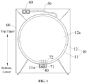
FIG. 1 is a simplified schematic diagram of a clothes treatment device according to an embodiment of the application. -
FIG. 2 is a schematic structural diagram of part of a clothes treatment device according to an embodiment of the application. -
FIG. 3 is a partially enlarged schematic diagram of A inFIG. 2 . -
FIG. 4 is a schematic exploded view of a drum assembly according to an embodiment of the application. -
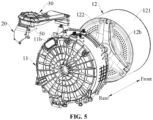
FIG. 5 is a schematic exploded view of a clothes treatment device according to an embodiment of the application. -
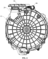
FIG. 6 is a schematic rear view of a clothes treatment device according to an embodiment of the application. -
FIG. 7 is a schematic structural diagram of a connector according to an embodiment of the application. -
FIG. 8 is another schematic structural diagram of a connector according to an embodiment of the application. -
-
drum assembly 10;outer tub 11;water storage area 11a; penetration opening 11b;rear side wall 111; -
circumferential side wall 112;inner tub 12;clothes treatment chamber 12a; throughhole 12b;circumferential tub wall 121; -
rear wall 122;connector 20;water inlet 21;water outlet 22; communication opening 23;mounting hole 24; -
rib 25;drying channel assembly 30;first heating member 40; firstwater supply pipeline 50;box body 60; -
low level sensor 71;high level sensor 72;water supply valve 80; secondwater supply pipeline 90. - In order to make the purpose, technical solutions and advantages of the application clearer, the application will be described in further detail below with reference to the drawings. The described embodiments should not be considered as limitations on the application. All other embodiments obtained by those of ordinary skill in the art without paying any creative work fall within the scope of protection of the application.
- In descriptions of the application, reference is made to "some embodiments", which describe a subset of all possible embodiments; however, it may be understood that "some embodiments" may be the same subset or different subsets of all possible embodiments, and may be combined with each other without conflict.
- In the descriptions of the application, reference is made to terms "first", "second" or the like, which are only intended to distinguish similar objects, and do not represent a specific order for the objects. It may understood that specific orders or sequences of "first", "second" or the like may be interchanged if allowable, to enable the embodiments of the application described here to be implemented in orders other than those illustrated or described here. Unless stated otherwise, "multiple" means at least two.
- In the descriptions of the application, it should be understood that orientation or positional relationships indicated by terms "upper", "lower", "front", "rear", "left", "right", "vertical", "horizontal", "top", "bottom", "inner", "outer", or the like are based on orientation or positional relationships shown in the drawings, and are only intended to facilitate describing the application and simplifying the descriptions, rather than indicating or implying that the referred device or element must have a particular orientation, configure and operate in a particular orientation, and thus should not be understood as limitation of the application.
- In the descriptions of the application, it should be noted that unless otherwise specified and defined clearly, terms "mount", "connect" and "connecting" should be understood in a broad sense, for example, it may be a fixed connection, or a detachable connection, or an integral connection; may be a mechanical connection, or an electrical connection; may be a direct connection, or an indirect connection through an intermediate medium; may be internal communication between two elements. Specific meanings of the above terms in the application may be understood by those of ordinary skill in the art according to specific cases.
- In the application, unless otherwise specified and defined clearly, a first feature being "above" or "below" a second feature may include that the first feature is in direct contact with the second feature, or may include that the first feature is not in direct contact with the second feature, instead, in contact with the second feature through additional features there-between. Furthermore, a first feature being "above", "over" and "on top of" a second feature includes that the first feature is directly above and obliquely above the second feature, or simply means that a horizontal height of the first feature is higher than that of the second feature. A first feature being "below", "under" and "underneath" a second feature includes that the first feature is directly below and obliquely below the second feature, or simply means that a horizontal height of the first feature is lower than that of the second feature.
- An embodiment of the application provides a clothes treatment device, with reference to
FIG. 1 to FIG. 6 , the clothes treatment device includes adrum assembly 10, afirst heating member 40, a firstwater supply pipeline 50, aconnector 20, and a controller (not shown in the figures). Thedrum assembly 10 includes anouter tub 11 and aninner tub 12 rotatably arranged in theouter tub 11. Space in theinner tub 12 is aclothes treatment chamber 12a. A front end of thedrum assembly 10 in an axial direction is opened to form a clothes access opening, through which a user may take clothes out and put clothes in. - The first
water supply pipeline 50 is communicated with an external water source (such as tap-water), and awater supply valve 80 is arranged on the firstwater supply pipeline 50. An on/off state of thewater supply valve 80 controls whether the firstwater supply pipeline 50 is communicated with the external water source. - With reference to
FIG. 1 to FIG. 4 , awater storage area 11a is provided in interior of theouter tub 11. Thefirst heating member 40 is arranged in thewater storage area 11a, and may heat water in thewater storage area 11a. - Exemplarily, as shown in
FIG. 1 , the clothes treatment device includes abox body 60, and thedrum assembly 10 is arranged in thebox body 60. - It may be understood that the
inner tub 12 is provided with multiple throughholes 12b, and airflow and/or water flow may be exchanged with theclothes treatment chamber 12a between theinner tub 12 and theouter tub 11 through multiple throughholes 12b. A number of the throughholes 12b may not be limited, as long as exchange of airflow and/or water flow between theinner tub 12 and theouter tub 11 may be met. - Specific shapes of the through
hole 12b are not limited, for example, the shape of the throughhole 12b may be a circle, an ellipse, a polygon, or the like, which is not specifically limited here. - Specific positions of the through
hole 12b on theinner tub 12 are not limited. Exemplarily, in some embodiments, all the throughholes 12b are arranged on acircumferential tub wall 121 of theinner tub 12; in some other embodiments, all the throughholes 12b are arranged on arear wall 122 at one end of theinner tub 12 away from the clothes access opening; in some other embodiments, part of the throughholes 12b are arranged on thecircumferential tub wall 121 of theinner tub 12, and another part of the throughholes 12b are arranged on arear wall 122 of theinner tub 12 in the axial direction. No specific limitation is made thereto. - Exemplarily, the
connector 20 is arranged on theouter tub 11, and is provided with a water supply structure configured to guide water in the firstwater supply pipeline 50 to the interior of theouter tub 11. That is, water on the firstwater supply pipeline 50 may be guided to the interior of theouter tub 11 by the water supply structure, and converged to thewater storage area 11a in theouter tub 11 under an action of gravity. - Exemplarily, the controller is configured to control an operation state of the
water supply valve 80 based on a water level of thewater storage area 11a in a steam washing mode (the steam washing mode referred in the embodiment includes steam utilization in a washing process, and also includes steam utilization in a drying process), so that thewater storage area 11a is within a set water level range, and control thefirst heating member 40 to heat water in thewater storage area 11a within the set water level range, to generate steam. The generated steam may enter theclothes treatment chamber 12a through the above throughholes 12b, to care clothes in theclothes treatment chamber 12a. - It should be noted that the steam washing mode is mainly based on the steam generated by heating, to perform sterilization, deodorization, ironing and other types of care to clothes in the
clothes treatment chamber 12a. Therefore, in the steam washing mode, water should be prevented from entering to wet clothes as much as possible. - The set water level range may meet a safe water level required for heating by the
first heating member 40, to prevent thefirst heating member 40 from dry-burning and damaging itself and surrounding devices, and the set water level range may prevent water in thewater storage area 11a from entering theinner tub 12 to wet clothes. Exemplarily, the set water level range is higher than a highest position of thefirst heating member 40 and is lower than a lowest point of a rotation trajectory of theinner tub 12, so that, the water level of thewater storage area 11a is at the safe water level in a heating process of thefirst heating member 40. - According to the clothes treatment device of the embodiment of the application, when a steam mode needs to be turned on, water in the first
water supply pipeline 50 is guided to the interior of theouter tub 11 by the water supply structure on theconnector 20, which may prevent water from entering to wet clothes as a traditional method; furthermore, thewater supply valve 80 on the firstwater supply pipeline 50 is controlled based on the water level of thewater storage area 11a, so that thewater storage area 1 1a is within the set water level range; the heating member heats water in thewater storage area 11a and generates steam, and sterilization, deodorization, ironing and other types of care are performed by the steam to clothes in theclothes treatment chamber 12a; arrangement of additional steam generators are not required, and space in theouter tub 11 is used to mount the heating member, such structure is simple, so that structure of the clothes treatment device is compact; furthermore, the water supply structure arranged on theconnector 20 may prevent wetting clothes in a process of supplying water to thewater storage area 11a, which is beneficial to meet requirements of steam washing and improve the user's experience. - Exemplarily, as shown in
FIG. 7 andFIG. 8 , the water supply structure on theconnector 20 includes awater inlet 21 and awater outlet 22. Thewater inlet 21 is opened on theconnector 20, is located at an outer side of theouter tub 11, and is connected to the firstwater supply pipeline 50. Thewater outlet 22 is opened on theconnector 20 and is located at an inner side of theouter tub 11. Correspondingly, theouter tub 11 is provided, at a position where theconnector 20 is mounted, with apenetration opening 1 1b into which thewater outlet 22 extends. - It should be noted that a side wall of the
outer tub 11 includes acircumferential side wall 112 and arear side wall 111, and thepenetration opening 11b may be arranged on thecircumferential side wall 112 or on therear side wall 111, which is not limited here. - Exemplarily, as shown in
FIG. 5 , thepenetration opening 11b is arranged on arear side wall 111 of theouter tub 11 along an axial direction, and theconnector 20 is arranged behind therear side wall 111. In this way, not only mounting space of theconnector 20 is saved, but also thewater outlet 22 may be positioned behind therear side wall 111 of theinner tub 12 after extending into theouter tub 11, thereby preventing water flowing out of thewater outlet 22 from directly entering theinner tub 12 to wet clothes. - Exemplarily, the
connector 20 is provided with a mountinghole 24, therear side wall 111 of theouter tub 11 may be provided with a mounting position cooperated with the mounting hole, and theconnector 20 may be locked tightly by screws to be fixed on theouter tub 11. For example, as shown inFIG. 6 , theconnector 20 is locked tightly by four screws to be fixed on therear side wall 111 of theouter tub 11. - In some embodiments, the clothes treatment device further includes a drying
channel assembly 30. Theconnector 20 further communicates the interior of theouter tub 11 to an inlet of the dryingchannel assembly 30. Correspondingly, at least a part of the steam enters theinner tub 12 after sequentially passing through theconnector 20 and the dryingchannel assembly 30. - Exemplarily, the clothes treatment device includes a drying
channel assembly 30 arranged at a top side of theouter tub 11 and a front door seal arranged at a front side of thedrum assembly 10, a hollow structure is present in interior of theconnector 20, and acommunication opening 23 connected to an inlet of the dryingchannel assembly 30 is arranged at top of theconnector 20, so that thewater outlet 22 of theconnector 20 may be used as an air inlet of the dryingchannel assembly 30. An air inlet of theinner tub 12 may be arranged at top of the front door seal, and an air outlet of the dryingchannel assembly 30 is communicated with the air inlet of theinner tub 12. - It may be understood that a second heating member and a fan may be arranged in the drying
channel assembly 30; and the controller further controls operation of the fan and operation of the second heating member in the steam washing mode. The fan may provide a blowing force for airflow in theouter tub 11 to flow into the dryingchannel assembly 30, and the second heating member may reheat the airflow in the dryingchannel assembly 30, thereby generating steam and/or superheated steam. For example, part of the steam generated by heating of the first heating member may be mixed with clothes in theclothes treatment chamber 12a by passing through the throughholes 12b of theinner tub 12 to perform sterilization, deodorization, ironing and other types of care to the clothes, and part of the steam may also flow from bottom to top, enter the dryingchannel assembly 30 after sequentially passing through thewater outlet 22 and thecommunication opening 23, and is reheated by the second heating member to form superheated steam, and then the superheated steam passes through the air inlet of theinner tub 12 to perform care to the clothes in theclothes treatment chamber 12a. In this way, care of the clothes in theclothes treatment chamber 12a by dual steam (steam generated by heating of thefirst heating member 40 and superheated steam generated by heating of the second heating member) may be achieved, which may effectively improve operation efficiency in the steam washing mode. - It should be noted that after the steam heated by the
first heating member 40 is introduced into the dryingchannel assembly 30, the steam may be converted into gaseous superheated steam after reheating by the second heating member, that is, water vapor with temperature ≥ 100°C; the superheated steam is introduced into theinner tub 12 under an action of the fan to perform sterilization, deodorization, ironing and other types of care to the clothes in theclothes treatment chamber 12a, the superheated steam may achieve effects of sterilization, deodorization and ironing better, which is beneficial to improve the user's experience. - Specific types of the
first heating member 40 and the second heating member are not limited here, as long as the first heating member and the second heating member may play a heating role. Exemplarily, each of thefirst heating member 40 and the second heating member may be an electric heating tube. - It should be noted that the steam washing mode may be an independent treatment program, or may be a treatment process in a certain treatment program. For example, the steam washing mode may also be a treatment process in a drying mode, to eliminate creases of the clothes after drying. Similarly, the drying mode may be an independent treatment program, or may be a treatment process in a certain treatment program. In some specific treatment programs, the steam washing mode and the drying mode may coexist.
- Exemplarily, the
penetration opening 11b on theouter tub 11 is opened at a position close to a top end of therear side wall 111, that is, thepenetration opening 1 1b is arranged at an upper part of therear side wall 111, that is, position of thepenetration opening 1 1b is higher than a height where a rotation center line of theinner tub 12 is located. Correspondingly, theconnector 20 is mounted at an upper part of the rear side wall 111 (as shown inFIG. 6 ). Based on such structure, a water outlet position of thewater outlet 22 may be made higher. In this way, water flowing out of thewater outlet 22 may exchange heat with steam in theouter tub 11 entering the dryingchannel assembly 30 from bottom to top along thewater outlet 22, so that water entering thewater storage area 11a may be preheated, and thefirst heating member 40 may reduce time-consuming and energy consumption required by heating to generate steam, which is beneficial to timely generate steam required by steam washing in theouter tub 11 and accelerate steam generation efficiency in theouter tub 11. - It may be understood that the
water outlet 22 on theconnector 20 is not only used as an outlet of water in the firstwater supply pipeline 50, but also used as an inlet for airflow in theouter tub 11 to enter the dryingchannel assembly 30. Water in the firstwater supply pipeline 50 may be fully mixed with airflow which will enter the dryingchannel assembly 30, to perform heat exchange there-between, and water exported from thewater outlet 22 may also be mixed with airflow (i.e., steam) flowing from bottom to top under an action of gravity, to perform heat exchange there-between, so that temperature of water converged to a water storage opening may reach a set temperature, which may shorten time of heating by thefirst heating member 40 to generate steam and accelerate steam generation efficiency in theouter tub 11. - In some embodiments, the
connector 20 is provided with a lint blocking structure configured to filter lint in the air, and water in the firstwater supply pipeline 50 is also used to clean the lint blocking structure. - It may be understood that in the steam washing mode, lint and other impurities are easily carried in the steam after mixing with clothes, and the lint blocking structure may filter lint and other impurities in the airflow. Water in the first
water supply pipeline 50 is also used to clean the lint blocking structure, that is, water flow for removing lint may be used to achieve steam for inflow of water, which may not only simplify structural setting of the water supply pipeline and but also prevent a traditional inflow way of water from wetting clothes, thereby achieving unified control of removing lint automatically and replenishing water by steam in the steam washing mode. - In some embodiments, the lint blocking structure includes a filter screen and/or
ribs 25. The filter screen is arranged at awater outlet 22 of the water supply structure, to prevent the lint from entering an inner cavity of theconnector 20. Theribs 25 are arranged in at least a part of area of the inner cavity of theconnector 20, to adsorb the lint. - In an example, the filter screen is arranged at the
water outlet 22, so that lint and other impurities may be effectively prevented from entering the dryingchannel assembly 30 along with the airflow. - In another example, the filter screen may be omitted,
multiple ribs 25 are arranged in the inner cavity of theconnector 20, a groove betweenadjacent ribs 25 may effectively absorb lint and other impurities carried in airflow passing through it, and such impurities may be automatically cleaned by water flow of the firstwater supply pipeline 50, which may also achieve an effect of effectively prevent lint and other impurities from entering the dryingchannel assembly 30 along with the airflow. Theribs 25 in the inner cavity of theconnector 20 may be integrally formed on an inner wall of theconnector 20. - In some embodiments, the water supply structure further includes a spray structure (not shown in the figures). The spray structure is communicated with the
water inlet 21, is configured to form spray water in an inner cavity of theconnector 20, and is provided with an outlet facing toward the lint blocking structure, to clean lint attached to the inner wall of theconnector 20 or lint on the filter screen. Exemplarily, the spray structure may be a venturi-shaped nozzle opened on the inner wall of theconnector 20, so that spray water is formed in the inner cavity of theconnector 20, and the spray water may enhance an effect of cleaning lint attached to the inner wall of theconnector 20, and may prevent lint and other impurities on clothes from being brought into the dryingchannel assembly 30 in the steam washing process to result in potential safety hazards. It may be understood that the water supply structure has dual functions of providing a water source to thefirst heating member 40 and cleaning lint, which may reduce arrangement of pipelines on the clothes treatment device and further reduce cost of the device. - Exemplarily, in some embodiments, a
rear wall 122 of theinner tub 12 along an axial direction is provided with multiple throughholes 12b, and a distance between each of the throughholes 12b and a rotation axis of theinner tub 12 is less than or greater than a distance between thepenetration opening 11b and the rotation axis of theinner tub 12. That is, in a plane projection perpendicular to the rotation axis of theinner tub 12, the distance between thepenetration opening 11b and the rotation axis of theinner tub 12 is greater than or less than a rotation radius corresponding to each of the throughholes 12b, that is, a projection of the throughhole 11b on therear wall 122 of theinner tub 12 along the axial direction does not coincide with an area where each of the throughholes 12b is located. In this way, water exported from thewater outlet 22 may be effectively prevented from directly entering theinner tub 12 through the throughholes 12b on theinner tub 12 to wet clothes. - In some embodiments, the controller controls the
inner tub 12 to rotate at a set rotation speed in the steam washing mode. - It may be understood that during rotation of the
inner tub 12, at least a part of water flowing from thewater outlet 22 into theouter tub 11 will be ejected out by the axialrear wall 122 in a rotation state, reducing a possibility of water flow entering theclothes treatment chamber 12a from the throughholes 12b, thereby reducing a possibility of the water flow wetting the clothes in theclothes treatment chamber 12a. Furthermore, during rotation of theinner tub 12, a trajectory swept by thewater outlet 22 on the axialrear wall 122 of theinner tub 12 is substantially a circular area, and theinner tub 12 is not provided with throughholes 12b corresponding to the circular area. In this way, even though water flow flowing from thewater outlet 22 into theouter tub 11 rushes towards the axialrear wall 122 of theinner tub 12 at a high speed, the water flow will be blocked by the axialrear wall 122 and will not pass through the throughholes 12b directly. In this way, it may reduce a possibility of water flow from thewater outlet 22 entering theclothes treatment chamber 12a, thereby reducing a possibility of water wetting the clothes in theclothes treatment chamber 12a in the steam washing mode. - In the embodiment of the application, specific structures of the
connector 20 are not limited. Exemplarily, theconnector 20 may be a structure fitted with an upper side of therear side wall 111 of theouter tub 11, thewater outlet 22 extends into the interior of theouter tub 11 from thepenetration opening 11b of theouter tub 11, and thewhole connector 20 is arranged to cover at thepenetration opening 11b and is connected to thepenetration opening 11b in a sealed manner. Thepenetration opening 23 of theconnector 20 is connected to the inlet of the dryingchannel assembly 30. Theconnector 20 has a small volume, and a mounting space required by theconnector 20 is small too. In case that size of thedrum assembly 10 of the clothes treatment device is the same, the clothes treatment device of the embodiment has a smaller appearance size in axial and height directions. - In some embodiments, a part of area at bottom of the
outer tub 11 is protruded downward to form thewater storage area 11a recessed at an inner side of theouter tub 11. With reference toFIG. 1 , position of thewater storage area 11a is lower than the lowest point of the rotation trajectory of theinner tub 12, and water entering theouter tub 11 from thewater outlet 22 may be converged to thewater storage area 11a under an action of gravity, and water may be converged to thewater storage area 11a without providing a special flow guiding structure. - In some embodiments, the clothes treatment device further includes a
low level sensor 71 and ahigh level sensor 72, both thelow level sensor 71 and thehigh level sensor 72 are configured to detect a water level of thewater storage area 11a. Both thelow level sensor 71 and thehigh level sensor 72 are arranged on arear side wall 111 of theouter tub 11 along an axial direction. A detected water level of thehigh level sensor 72 is higher than a detected water level of thelow level sensor 71 and is lower than a lowest point of a rotation trajectory of theinner tub 12, and the detected water level of thelow level sensor 71 is higher than a highest position of thefirst heating member 40. Both thelow level sensor 71 and thehigh level sensor 72 are communicatively connected to the controller, thelow level sensor 71 and thehigh level sensor 72 send detection signals respectively, and the controller identifies whether the water level of thewater storage area 11a is appropriate according to the detection signals. - Mounting positions of the
low level sensor 71 and thehigh level sensor 72 are not limited. Exemplarily, with reference toFIG. 2 , both thelow level sensor 71 and thehigh level sensor 72 are arranged on therear side wall 111 of theouter tub 11. On one hand, it facilitates mounting from the rear of therear side wall 111, and on the other hand, it also facilitates arranging wires of thelow level sensor 71, thehigh level sensor 72 and the heating member at a rear side of therear side wall 111 centrally. - Specific types of the
low level sensor 71 are not limited, as long as thelow level sensor 71 may detect the water level. Specific types of thehigh level sensor 72 are not limited, as long as thehigh level sensor 72 may detect the water level. - In some embodiments, the controller configured to control the operation state of the
water supply valve 80 based on the water level of thewater storage area 11a includes: - the controller controls the
water supply valve 80 to be closed, in response to determining that the water level of thewater storage area 11a is higher than the detected water level of thehigh level sensor 72 based on a detection signal of thehigh level sensor 72; and - the controller controls the
water supply valve 80 to be opened, in response to determining that the water level of thewater storage area 11a is lower than the detected water level of thelow level sensor 71 based on a detection signal of thelow level sensor 71. - It may be understood that when the controller determines that the water level of the
water storage area 11a is higher than the detected water level of thehigh level sensor 72 based on the detection signal of thehigh level sensor 72, then the controller determines a risk of water in thewater storage area 11a overflowing into theinner tub 12, and controls thewater supply valve 80 to be closed, thereby stopping water supplying from thewater outlet 22 to theouter tub 11; when the controller determines that the water level of thewater storage area 11a is lower than the detected water level of thelow level sensor 71 based on the detection signal of thelow level sensor 71, then the controller determines that amount of water in thewater storage area 11a is relatively low, and controls thewater supply valve 80 to be opened, to supply water from thewater outlet 22 to theouter tub 11 so as to replenish water for thewater storage area 11a. In this way, in the steam washing mode, the water level of thewater storage area 11a may always be kept at a set safe water level, which may meet requirements of thefirst heating member 40 generating steam by heating. - In some embodiments, the clothes treatment device further includes a second water supply pipeline 90 (as shown in
FIG. 6 ) configured to supply washing water to theouter tub 11. The secondwater supply pipeline 90 may be an inlet corrugated pipe, and awater outlet 22 of the inlet corrugated pipe may directly inject water into theouter tub 11, and during injection of water, water flow may enter theclothes treatment chamber 12a through the throughholes 12b on theinner tub 12, and water in theouter tub 11 may also enter theclothes treatment chamber 12a through the throughholes 12b on theinner tub 12, thereby wetting clothes sufficiently. The controller is further configured to control thefirst heating member 40 to heat the washing water in a washing mode. - It may be understood that there is a set water level for heating and washing in the washing mode, and the controller determines that a water level of the
outer tub 11 reaches the set water level, and controls thefirst heating member 40 to heat the washing water, thereby achieving an effect of heating and washing. In this way, thefirst heating member 40 in the embodiment of the application may achieve sharing of heating during heating and washing with heating during steam washing. Therefore, cost of the device may be saved. - Exemplarily, the second
water supply pipeline 90 and the firstwater supply pipeline 50 may share thewater supply valve 80. For example, thewater supply valve 80 may be a three-way valve provided with an inlet, a first outlet and a second outlet, the inlet is communicated with an external water source, the first outlet is communicated with the firstwater supply pipeline 50, and the second outlet is communicated with the secondwater supply pipeline 90. In the steam washing mode, the first outlet of thewater supply valve 80 is controlled to open, so that the firstwater supply pipeline 50 supplies water to theouter tub 11, to prevent water from entering to wet clothes in the steam washing mode. In the washing mode, the second outlet of thewater supply valve 80 is controlled to open, so that the secondwater supply pipeline 90 supplies water to theouter tub 11. - It may be known from the above descriptions that the clothes treatment device of the embodiment of the application may share the
first heating member 40 heating the washing water, to heat water in the water storage area within theouter tub 11 to generate steam, and the second heating member in the drying channel may reheat steam to form superheated steam, thereby improving operation efficiency of steam washing; furthermore, in the steam washing mode, the water supply structure arranged on theconnector 20 supplies water to theouter tub 11, which may prevent clothes in theinner tub 12 from getting wet in the water supply process, and may remove lint and other impurities carried in the airflow, to avoid potential safety hazards caused by impurities entering the dryingchannel assembly 30. - It should be noted that the technical solutions described in the embodiments of the application may be combined arbitrarily without conflict.
- The above descriptions are only specific implementations of the application, however, the scope of protection of the application is not limited thereto. Any variation or replacement easily conceived by those skilled in the art within the technical scope disclosed by the application should be included in the scope of protection of the application. Therefore, the scope of protection of the application should be subjected to the scope of protection of claims.
Claims (14)
- A clothes treatment device, comprising:a drum assembly, comprising an outer tub and an inner tub rotatably arranged in the outer tub, a water storage area being provided in the interior of the outer tub;a first heating member, arranged in the water storage area;a first water supply pipeline, on which a water supply valve is arranged;a connector, arranged on the outer tub, and provided with a water supply structure configured to guide water in the first water supply pipeline to the interior of the outer tub;a controller, configured to control an operation state of the water supply valve based on a water level of the water storage area in a steam washing mode, and control the first heating member to heat water in the water storage area to generate steam.
- The clothes treatment device of claim 1, further comprising a drying channel assembly,the connector further communicating the interior of the outer tub to an inlet of the drying channel assembly,correspondingly, at least a part of the steam entering the inner tub after sequentially passing through the connector and the drying channel assembly.
- The clothes treatment device of claim 1, wherein the connector is provided with a lint blocking structure configured to filter lint in the air, and water in the first water supply pipeline is also used to clean the lint blocking structure.
- The clothes treatment device of claim 3, wherein the lint blocking structure comprises:a filter screen, arranged at a water outlet of the water supply structure, to prevent the lint from entering an inner cavity of the connector; and/orribs, arranged in at least a part of area of the inner cavity of the connector, to adsorb the lint.
- The clothes treatment device of claim 3, wherein the water supply structure further comprises:
a spray structure, communicated with a water inlet of the water supply structure, configured to form spray water in an inner cavity of the connector, and provided with an outlet facing toward the lint blocking structure. - The clothes treatment device of claim 2, wherein the drying channel assembly comprises a second heating member and a fan, and
the controller further controls operation of the fan and operation of the second heating member in the steam washing mode. - The clothes treatment device of claim 2, wherein the water supply structure comprises:a water inlet, opened on the connector, located at an outer side of the outer tub, and connected to the first water supply pipeline; anda water outlet, opened on the connector and located at an inner side of the outer tub,the outer tub being provided, at a position where the connector is mounted, with a penetration opening into which the water outlet extends.
- The clothes treatment device of claim 7, wherein the penetration opening is arranged on a rear side wall of the outer tub along an axial direction, and the connector is arranged behind the rear side wall.
- The clothes treatment device of claim 7, wherein a rear wall of the inner tub along an axial direction is provided with a plurality of through holes, and a distance between each of the through holes and a rotation axis of the inner tub is less than or greater than a distance between the penetration opening and the rotation axis of the inner tub.
- The clothes treatment device of claim 1, wherein the controller controls the inner tub to rotate at a set rotation speed in the steam washing mode.
- The clothes treatment device of claim 1, wherein a part of the area at the bottom of the outer tub is protruded downward to form the water storage area recessed at an inner side of the outer tub.
- The clothes treatment device of claim 1, further comprising a low level sensor and a high level sensor,both the low level sensor and the high level sensor being arranged on a rear side wall of the outer tub along an axial direction,a detected water level of the high level sensor being higher than a detected water level of the low level sensor and lower than a lowest point of a rotation trajectory of the inner tub, and the detected water level of the low level sensor being higher than a highest position of the first heating member.
- The clothes treatment device of claim 12, wherein the controller configured to control the operation state of the water supply valve based on the water level of the water storage area comprises:the controller controls the water supply valve to be closed, in response to determining that the water level of the water storage area is higher than the detected water level of the high level sensor based on a detection signal of the high level sensor; andthe controller controls the water supply valve to be opened, in response to determining that the water level of the water storage area is lower than the detected water level of the low level sensor based on a detection signal of the low level sensor.
- The clothes treatment device of claim 1, further comprising a second water supply pipeline configured to supply washing water to the outer tub,
the controller further configured to control the first heating member to heat the washing water in a washing mode.
Applications Claiming Priority (2)
| Application Number | Priority Date | Filing Date | Title |
|---|---|---|---|
| CN202110395057.6A CN113201899B (en) | 2021-04-13 | 2021-04-13 | Clothes treating apparatus |
| PCT/CN2021/090780 WO2022217657A1 (en) | 2021-04-13 | 2021-04-28 | Clothes treatment device |
Publications (2)
| Publication Number | Publication Date |
|---|---|
| EP4310238A1 true EP4310238A1 (en) | 2024-01-24 |
| EP4310238A4 EP4310238A4 (en) | 2024-09-04 |
Family
ID=77026723
Family Applications (1)
| Application Number | Title | Priority Date | Filing Date |
|---|---|---|---|
| EP21936530.1A Pending EP4310238A4 (en) | 2021-04-13 | 2021-04-28 | DEVICE FOR TREATING GARMENTS |
Country Status (4)
| Country | Link |
|---|---|
| EP (1) | EP4310238A4 (en) |
| CN (1) | CN113201899B (en) |
| BR (1) | BR112023021027A2 (en) |
| WO (1) | WO2022217657A1 (en) |
Families Citing this family (5)
| Publication number | Priority date | Publication date | Assignee | Title |
|---|---|---|---|---|
| CN113152025B (en) * | 2021-04-13 | 2022-03-22 | 无锡小天鹅电器有限公司 | Drum assembly and clothes treatment equipment |
| CN113981647A (en) * | 2021-09-01 | 2022-01-28 | 北京石头世纪科技股份有限公司 | Washing and drying integrated machine |
| CN218508087U (en) * | 2022-08-31 | 2023-02-21 | 深圳洛克创新科技有限公司 | Washing and drying integrated machine |
| EP4361336B1 (en) * | 2022-10-24 | 2025-06-04 | Arçelik Anonim Sirketi | A laundry washer/dryer control method with hygiene program |
| CN119571573A (en) * | 2023-08-31 | 2025-03-07 | 南京石头创新科技有限公司 | Water supply control method and device, clothes treatment equipment and storage medium |
Family Cites Families (21)
| Publication number | Priority date | Publication date | Assignee | Title |
|---|---|---|---|---|
| JP3773932B2 (en) * | 2003-09-29 | 2006-05-10 | 三洋電機株式会社 | Drum washing machine |
| US7600402B2 (en) * | 2003-11-04 | 2009-10-13 | Lg Electronics Inc. | Washing apparatus and control method thereof |
| KR100587330B1 (en) * | 2003-11-04 | 2006-06-08 | 엘지전자 주식회사 | Driving method for laundry dryer and its dry cleaning mode |
| US8291731B2 (en) * | 2005-05-31 | 2012-10-23 | Lg Electronics Inc. | Washing machine generating and using the steam |
| KR100789824B1 (en) * | 2005-05-31 | 2008-01-02 | 엘지전자 주식회사 | Laundry device |
| KR100833857B1 (en) * | 2005-05-31 | 2008-06-02 | 엘지전자 주식회사 | Laundry device |
| KR100867122B1 (en) * | 2007-04-17 | 2008-11-06 | 삼성전자주식회사 | Washing machine and control method |
| US20110197638A1 (en) * | 2010-02-17 | 2011-08-18 | Bsh Home Appliances Corporation | Steam generator for domestic household appliance |
| CN202401276U (en) * | 2011-11-29 | 2012-08-29 | 南京乐金熊猫电器有限公司 | Outer drum of washing machine |
| PL2604738T3 (en) * | 2011-12-12 | 2017-08-31 | Electrolux Home Products Corporation N.V. | Washing machine with integrated steam generator |
| EP2623662B1 (en) * | 2012-02-06 | 2018-04-04 | LG Electronics Inc. | Laundry machine and control method thereof |
| DE102013100872B3 (en) * | 2013-01-29 | 2014-02-27 | Miele & Cie. Kg | Front loading type washing machine has vapor collection chamber that is connected with steam line such that vapor from vapor collection chamber is passed into laundry drum, and collecting device which is arranged above heating element |
| CN105506920B (en) * | 2014-09-23 | 2018-01-16 | 无锡小天鹅股份有限公司 | Roller washing machine and its Ironing method |
| CN106319826B (en) * | 2015-06-29 | 2021-04-27 | 青岛海尔滚筒洗衣机有限公司 | A washing machine with steam washing function and control method |
| KR102350480B1 (en) * | 2017-03-10 | 2022-01-17 | 삼성전자주식회사 | Washing machine and control method thereof |
| CN109023831B (en) * | 2017-06-08 | 2021-02-26 | 无锡小天鹅电器有限公司 | Washing and drying integrated machine |
| CN208250704U (en) * | 2018-01-03 | 2018-12-18 | 浙江韦氏电器有限公司 | A kind of outer cylinder water inlet pipe |
| CN108823909A (en) * | 2018-07-10 | 2018-11-16 | 海信(山东)冰箱有限公司 | A kind of roller washing machine and its control method |
| CN110857513A (en) * | 2018-08-24 | 2020-03-03 | 无锡小天鹅电器有限公司 | Laundry treatment apparatus and base assembly thereof |
| CN109267286B (en) * | 2018-11-02 | 2020-10-27 | 海信(山东)冰箱有限公司 | Drying washing machine |
| CN113152025B (en) * | 2021-04-13 | 2022-03-22 | 无锡小天鹅电器有限公司 | Drum assembly and clothes treatment equipment |
-
2021
- 2021-04-13 CN CN202110395057.6A patent/CN113201899B/en active Active
- 2021-04-28 BR BR112023021027A patent/BR112023021027A2/en active Search and Examination
- 2021-04-28 EP EP21936530.1A patent/EP4310238A4/en active Pending
- 2021-04-28 WO PCT/CN2021/090780 patent/WO2022217657A1/en not_active Ceased
Also Published As
| Publication number | Publication date |
|---|---|
| EP4310238A4 (en) | 2024-09-04 |
| CN113201899B (en) | 2022-08-26 |
| BR112023021027A2 (en) | 2023-12-12 |
| WO2022217657A1 (en) | 2022-10-20 |
| CN113201899A (en) | 2021-08-03 |
Similar Documents
| Publication | Publication Date | Title |
|---|---|---|
| CN113201899B (en) | Clothes treating apparatus | |
| US8438755B2 (en) | Laundry machine | |
| US8769997B2 (en) | Laundry machine | |
| EP1507030B1 (en) | Washing machine with vapour generator and water circulation | |
| US20090133281A1 (en) | Steam laundry dryer | |
| US20090293557A1 (en) | Steam Generator and Washing Machine Having the Same | |
| EP4061990B1 (en) | A laundry treating appliance having a vapor and/or mist and/or aerosol generator | |
| KR20080021938A (en) | Compound laundry machine | |
| KR100662473B1 (en) | Dryer using steam generator | |
| CN113502637A (en) | Washing machine | |
| EP1873298B1 (en) | Steam generating device and washing machine having the same | |
| CN113152025B (en) | Drum assembly and clothes treatment equipment | |
| JP2018524026A (en) | Clothing processing equipment | |
| KR20080012006A (en) | dryer | |
| CN213925504U (en) | Washing machine | |
| KR102153899B1 (en) | Laundry Treating Machine | |
| KR101387544B1 (en) | Cloth treating apparatus | |
| CN213804458U (en) | a washing machine | |
| KR100762337B1 (en) | Steam device of washing machine and control method | |
| CN113389030B (en) | Garment steamer | |
| CN220202240U (en) | Pulsator washing machine | |
| KR100833868B1 (en) | Steam dryer | |
| CN205152673U (en) | High -temperature steam's garment steamer fast spouts | |
| CN213804459U (en) | a washing machine | |
| CN213804462U (en) | a washing machine |
Legal Events
| Date | Code | Title | Description |
|---|---|---|---|
| STAA | Information on the status of an ep patent application or granted ep patent |
Free format text: STATUS: THE INTERNATIONAL PUBLICATION HAS BEEN MADE |
|
| PUAI | Public reference made under article 153(3) epc to a published international application that has entered the european phase |
Free format text: ORIGINAL CODE: 0009012 |
|
| STAA | Information on the status of an ep patent application or granted ep patent |
Free format text: STATUS: REQUEST FOR EXAMINATION WAS MADE |
|
| 17P | Request for examination filed |
Effective date: 20231017 |
|
| AK | Designated contracting states |
Kind code of ref document: A1 Designated state(s): AL AT BE BG CH CY CZ DE DK EE ES FI FR GB GR HR HU IE IS IT LI LT LU LV MC MK MT NL NO PL PT RO RS SE SI SK SM TR |
|
| DAV | Request for validation of the european patent (deleted) | ||
| DAX | Request for extension of the european patent (deleted) | ||
| A4 | Supplementary search report drawn up and despatched |
Effective date: 20240801 |
|
| RIC1 | Information provided on ipc code assigned before grant |
Ipc: D06F 105/46 20200101ALN20240726BHEP Ipc: D06F 105/30 20200101ALN20240726BHEP Ipc: D06F 105/28 20200101ALN20240726BHEP Ipc: D06F 103/18 20200101ALN20240726BHEP Ipc: D06F 58/22 20060101ALN20240726BHEP Ipc: D06F 39/40 20240101ALN20240726BHEP Ipc: D06F 33/69 20200101ALI20240726BHEP Ipc: D06F 25/00 20060101ALI20240726BHEP Ipc: D06F 33/00 20200101ALI20240726BHEP Ipc: D06F 39/04 20060101ALI20240726BHEP Ipc: D06F 39/00 20240101AFI20240726BHEP |
|
| STAA | Information on the status of an ep patent application or granted ep patent |
Free format text: STATUS: EXAMINATION IS IN PROGRESS |