EP4309934A1 - Vehicle window assembly and vehicle - Google Patents
Vehicle window assembly and vehicle Download PDFInfo
- Publication number
- EP4309934A1 EP4309934A1 EP22810135.8A EP22810135A EP4309934A1 EP 4309934 A1 EP4309934 A1 EP 4309934A1 EP 22810135 A EP22810135 A EP 22810135A EP 4309934 A1 EP4309934 A1 EP 4309934A1
- Authority
- EP
- European Patent Office
- Prior art keywords
- vehicle window
- light
- glass sheet
- light guide
- strip
- Prior art date
- Legal status (The legal status is an assumption and is not a legal conclusion. Google has not performed a legal analysis and makes no representation as to the accuracy of the status listed.)
- Granted
Links
Images



Classifications
-
- B—PERFORMING OPERATIONS; TRANSPORTING
- B60—VEHICLES IN GENERAL
- B60J—WINDOWS, WINDSCREENS, NON-FIXED ROOFS, DOORS, OR SIMILAR DEVICES FOR VEHICLES; REMOVABLE EXTERNAL PROTECTIVE COVERINGS SPECIALLY ADAPTED FOR VEHICLES
- B60J1/00—Windows; Windscreens; Accessories therefor
- B60J1/20—Accessories, e.g. wind deflectors, blinds
-
- B—PERFORMING OPERATIONS; TRANSPORTING
- B60—VEHICLES IN GENERAL
- B60J—WINDOWS, WINDSCREENS, NON-FIXED ROOFS, DOORS, OR SIMILAR DEVICES FOR VEHICLES; REMOVABLE EXTERNAL PROTECTIVE COVERINGS SPECIALLY ADAPTED FOR VEHICLES
- B60J10/00—Sealing arrangements
- B60J10/70—Sealing arrangements specially adapted for windows or windscreens
-
- B—PERFORMING OPERATIONS; TRANSPORTING
- B60—VEHICLES IN GENERAL
- B60J—WINDOWS, WINDSCREENS, NON-FIXED ROOFS, DOORS, OR SIMILAR DEVICES FOR VEHICLES; REMOVABLE EXTERNAL PROTECTIVE COVERINGS SPECIALLY ADAPTED FOR VEHICLES
- B60J10/00—Sealing arrangements
- B60J10/20—Sealing arrangements characterised by the shape
- B60J10/26—Sealing arrangements characterised by the shape characterised by the surface shape
-
- B—PERFORMING OPERATIONS; TRANSPORTING
- B60—VEHICLES IN GENERAL
- B60J—WINDOWS, WINDSCREENS, NON-FIXED ROOFS, DOORS, OR SIMILAR DEVICES FOR VEHICLES; REMOVABLE EXTERNAL PROTECTIVE COVERINGS SPECIALLY ADAPTED FOR VEHICLES
- B60J10/00—Sealing arrangements
- B60J10/20—Sealing arrangements characterised by the shape
- B60J10/26—Sealing arrangements characterised by the shape characterised by the surface shape
- B60J10/265—Sealing arrangements characterised by the shape characterised by the surface shape the surface being primarily decorative
-
- B—PERFORMING OPERATIONS; TRANSPORTING
- B60—VEHICLES IN GENERAL
- B60J—WINDOWS, WINDSCREENS, NON-FIXED ROOFS, DOORS, OR SIMILAR DEVICES FOR VEHICLES; REMOVABLE EXTERNAL PROTECTIVE COVERINGS SPECIALLY ADAPTED FOR VEHICLES
- B60J10/00—Sealing arrangements
- B60J10/30—Sealing arrangements characterised by the fastening means
- B60J10/34—Sealing arrangements characterised by the fastening means using adhesives
- B60J10/35—Sealing arrangements characterised by the fastening means using adhesives using adhesive tapes, e.g. double-sided tapes
-
- B—PERFORMING OPERATIONS; TRANSPORTING
- B60—VEHICLES IN GENERAL
- B60Q—ARRANGEMENT OF SIGNALLING OR LIGHTING DEVICES, THE MOUNTING OR SUPPORTING THEREOF OR CIRCUITS THEREFOR, FOR VEHICLES IN GENERAL
- B60Q1/00—Arrangement of optical signalling or lighting devices, the mounting or supporting thereof or circuits therefor
- B60Q1/26—Arrangement of optical signalling or lighting devices, the mounting or supporting thereof or circuits therefor the devices being primarily intended to indicate the vehicle, or parts thereof, or to give signals, to other traffic
- B60Q1/2661—Arrangement of optical signalling or lighting devices, the mounting or supporting thereof or circuits therefor the devices being primarily intended to indicate the vehicle, or parts thereof, or to give signals, to other traffic mounted on parts having other functions
- B60Q1/268—Arrangement of optical signalling or lighting devices, the mounting or supporting thereof or circuits therefor the devices being primarily intended to indicate the vehicle, or parts thereof, or to give signals, to other traffic mounted on parts having other functions on windscreens or windows
-
- B—PERFORMING OPERATIONS; TRANSPORTING
- B60—VEHICLES IN GENERAL
- B60Q—ARRANGEMENT OF SIGNALLING OR LIGHTING DEVICES, THE MOUNTING OR SUPPORTING THEREOF OR CIRCUITS THEREFOR, FOR VEHICLES IN GENERAL
- B60Q3/00—Arrangement of lighting devices for vehicle interiors; Lighting devices specially adapted for vehicle interiors
- B60Q3/20—Arrangement of lighting devices for vehicle interiors; Lighting devices specially adapted for vehicle interiors for lighting specific fittings of passenger or driving compartments; mounted on specific fittings of passenger or driving compartments
- B60Q3/208—Sun roofs; Windows
-
- B—PERFORMING OPERATIONS; TRANSPORTING
- B60—VEHICLES IN GENERAL
- B60Q—ARRANGEMENT OF SIGNALLING OR LIGHTING DEVICES, THE MOUNTING OR SUPPORTING THEREOF OR CIRCUITS THEREFOR, FOR VEHICLES IN GENERAL
- B60Q3/00—Arrangement of lighting devices for vehicle interiors; Lighting devices specially adapted for vehicle interiors
- B60Q3/50—Mounting arrangements
-
- B—PERFORMING OPERATIONS; TRANSPORTING
- B60—VEHICLES IN GENERAL
- B60Q—ARRANGEMENT OF SIGNALLING OR LIGHTING DEVICES, THE MOUNTING OR SUPPORTING THEREOF OR CIRCUITS THEREFOR, FOR VEHICLES IN GENERAL
- B60Q3/00—Arrangement of lighting devices for vehicle interiors; Lighting devices specially adapted for vehicle interiors
- B60Q3/60—Arrangement of lighting devices for vehicle interiors; Lighting devices specially adapted for vehicle interiors characterised by optical aspects
- B60Q3/62—Arrangement of lighting devices for vehicle interiors; Lighting devices specially adapted for vehicle interiors characterised by optical aspects using light guides
-
- B—PERFORMING OPERATIONS; TRANSPORTING
- B60—VEHICLES IN GENERAL
- B60Q—ARRANGEMENT OF SIGNALLING OR LIGHTING DEVICES, THE MOUNTING OR SUPPORTING THEREOF OR CIRCUITS THEREFOR, FOR VEHICLES IN GENERAL
- B60Q3/00—Arrangement of lighting devices for vehicle interiors; Lighting devices specially adapted for vehicle interiors
- B60Q3/70—Arrangement of lighting devices for vehicle interiors; Lighting devices specially adapted for vehicle interiors characterised by the purpose
- B60Q3/78—Arrangement of lighting devices for vehicle interiors; Lighting devices specially adapted for vehicle interiors characterised by the purpose for generating luminous strips, e.g. for marking trim component edges
-
- F—MECHANICAL ENGINEERING; LIGHTING; HEATING; WEAPONS; BLASTING
- F21—LIGHTING
- F21S—NON-PORTABLE LIGHTING DEVICES; SYSTEMS THEREOF; VEHICLE LIGHTING DEVICES SPECIALLY ADAPTED FOR VEHICLE EXTERIORS
- F21S43/00—Signalling devices specially adapted for vehicle exteriors, e.g. brake lamps, direction indicator lights or reversing lights
- F21S43/20—Signalling devices specially adapted for vehicle exteriors, e.g. brake lamps, direction indicator lights or reversing lights characterised by refractors, transparent cover plates, light guides or filters
- F21S43/235—Light guides
- F21S43/236—Light guides characterised by the shape of the light guide
- F21S43/237—Light guides characterised by the shape of the light guide rod-shaped
-
- F—MECHANICAL ENGINEERING; LIGHTING; HEATING; WEAPONS; BLASTING
- F21—LIGHTING
- F21S—NON-PORTABLE LIGHTING DEVICES; SYSTEMS THEREOF; VEHICLE LIGHTING DEVICES SPECIALLY ADAPTED FOR VEHICLE EXTERIORS
- F21S43/00—Signalling devices specially adapted for vehicle exteriors, e.g. brake lamps, direction indicator lights or reversing lights
- F21S43/20—Signalling devices specially adapted for vehicle exteriors, e.g. brake lamps, direction indicator lights or reversing lights characterised by refractors, transparent cover plates, light guides or filters
- F21S43/235—Light guides
- F21S43/253—Two or more juxtaposed light guides
-
- G—PHYSICS
- G02—OPTICS
- G02B—OPTICAL ELEMENTS, SYSTEMS OR APPARATUS
- G02B6/00—Light guides; Structural details of arrangements comprising light guides and other optical elements, e.g. couplings
- G02B6/0001—Light guides; Structural details of arrangements comprising light guides and other optical elements, e.g. couplings specially adapted for lighting devices or systems
- G02B6/0011—Light guides; Structural details of arrangements comprising light guides and other optical elements, e.g. couplings specially adapted for lighting devices or systems the light guides being planar or of plate-like form
- G02B6/0066—Light guides; Structural details of arrangements comprising light guides and other optical elements, e.g. couplings specially adapted for lighting devices or systems the light guides being planar or of plate-like form characterised by the light source being coupled to the light guide
- G02B6/0068—Arrangements of plural sources, e.g. multi-colour light sources
Definitions
- the disclosure relates to the field of vehicle moulding, and in particular, to a vehicle window assembly and a vehicle.
- Vehicles have always been one of important means of transportation for civilization. As people have higher and higher requirements on the aesthetic design of the vehicle, the use of a vehicle window assembly capable of emitting light on vehicle exteriors has gradually become popular, especially in well-known domestic or international mainstream automotive manufacturers, and the utilization of the vehicle window assembly capable of emitting light has become more prevalent.
- light emission of the vehicle window assembly mainly depends on defining a hole in a bright strip, and then arranging a light source or a light guide behind the hole to achieve a light emission effect.
- the hole in the bright strip destroys the sealing performance, optical performance, etc. of the bright strip, and additional cooperation between the hole and the light source is required, which increases the technical costs.
- a vehicle window assembly is provided in the disclosure to eliminate the need for defining a hole in a bright strip, thereby reducing the technical costs.
- a vehicle window assembly in a first aspect, includes multiple light guide strips spaced apart from each other, a vehicle window glass sheet, and a sealing box.
- the multiple light guide strips are arranged on one side surface of the vehicle window glass sheet, the sealing box is disposed at one side of each of the multiple light guide strips away from the vehicle window glass sheet, the sealing box defines grooves at positions respectively corresponding to the multiple light guide strips, and each of the multiple light guide strips is received in one of the grooves.
- the multiple light guide strips are received in the sealing box, the sealing box is directly fixed to the vehicle window glass sheet by the fixing member, thus there is no need to define a hole in the vehicle window glass sheet, thereby ensuring the sealing performance, optical performance, etc. of the vehicle window assembly and decreasing the technical costs.
- the vehicle window assembly further includes a bright strip and multiple light-emitting modules.
- the bright strip and the sealing box are opposite to each other to define a gap for accommodating the vehicle window glass sheet.
- Each of the multiple light-emitting modules is arranged within an orthographic projection of the bright strip on the vehicle window glass sheet, each of the multiple light-emitting modules defines a light-exiting opening, and a light ray exiting from the light-exiting opening corresponds to at least one of the multiple light guide strips.
- the bright strip includes a first bright portion and a second bright portion.
- the multiple light-emitting modules are arranged on the first bright portion, the second bright portion is connected to the first bright portion, the first bright portion and the second bright portion surround a space to define an accommodating region, and the multiple light guide strips are arranged within the accommodating region.
- each of the multiple light-emitting modules is configured to emit a light ray having a light intensity and color different from a light intensity and color of a light ray emitted by each of the other of the multiple light-emitting modules.
- the vehicle window assembly further includes multiple shielding members spaced apart from each other and multiple light-transmitting films spaced apart from each other, each of the multiple shielding members is adjacent to one of the multiple light-transmitting films, and an orthographic projection of each of the multiple light-transmitting films on the vehicle window glass sheet covers an orthographic projection of a corresponding light guide strip on the vehicle window glass sheet.
- a combination of an orthographic projection of each of the multiple shielding members on the vehicle window glass sheet and an orthographic projection of each of the multiple light-transmitting films on the vehicle window glass sheet covers an orthographic projection of the sealing box on the vehicle window glass sheet.
- each of the multiple light-transmitting films is configured to allow a light ray to pass through unidirectionally.
- the sealing box is integrally formed by injection molding.
- Each of the grooves has a semicircular shape, a rectangular shape, or a trapezoidal shape, or the grooves comprise various types of grooves among a semicircular groove, a rectangular groove, and a trapezoidal groove.
- the vehicle window assembly further includes fixing members.
- Each of the fixing members is configured to fix the sealing box to the vehicle window glass sheet.
- Each of the fixing members is an optical adhesive, a 3M TM adhesive, or a polyurethane adhesive, or the fixing members include various types of fixing members among the optical adhesive, the 3M TM adhesive, and the polyurethane adhesive.
- the vehicle window assembly further includes a hemming strip.
- the hemming strip is separated from the light guide strip and is configured to fix the vehicle window glass sheet.
- the vehicle window assembly further includes a bright strip, and the hemming strip and the bright strip cooperate to fix the vehicle window assembly to the hemming strip.
- a vehicle in a second aspect, is further provided.
- the vehicle includes a frame and the vehicle window assembly provided in the first aspect, and the vehicle window assembly is mounted to the frame.
- vehicle window assembly-1 light guide strip-11, vehicle window glass sheet-12, sealing box-13, groove-131, fixing member-14, bright strip-15, first bright portion-151, second bright portion-152, accommodating region-153, light-emitting module-16, shielding member-17, light-transmitting film-18, hemming strip-19, vehicle-2, frame-21.
- FIG. 1 is a schematic diagram of the vehicle window assembly according to an embodiment of the disclosure
- FIG. 2 is a schematic cross-sectional view taken along line I-I in FIG. 1
- the vehicle window assembly 1 includes multiple light guide strips 11 spaced apart from each other, the vehicle window glass sheet 12, and a sealing box 13.
- the multiple light guide strips 11 are arranged on one side surface of the vehicle window glass sheet 12.
- the sealing box 13 is disposed at one side of each of the multiple light guide strips 11 away from the vehicle window glass sheet 12.
- the sealing box 13 defines grooves 131 at positions respectively corresponding to the multiple light guide strips 11, and each of the multiple light guide strips 11 is received in one of the grooves 131.
- the light guide strip 11 can guide light incident on an interface of the light guide strip 11 to the entire light guide strip 11, thereby achieving illumination of the light guide strip 11 when exposed to light.
- the material of an inner side wall of the light guide strip 11 has high light reflectivity, so that the light is not subject to excessive lost during transmission in the light guide strip 11, thereby allowing the light to be transmitted in the entire light guide strip 11.
- the vehicle window assembly 1 further includes fixing members 14.
- Each of the fixing members 14 is configured to fix the sealing box 13 to the vehicle window glass sheet 12.
- the multiple light guide strips 11 are arranged in parallel, and at the same time, in order to avoid affecting a visible range of the vehicle window glass sheet 12, the multiple light guide strips 11 are arranged adjacent to a periphery of the vehicle window glass sheet 12 (for example, an upper edge, a lower edge, a left edge, or a right edge of the vehicle window glass sheet 12).
- the multiple light guide strips 11 may also be arranged to overlap or arranged at a certain angle to one another, which is not limited in the disclosure.
- the grooves 131 defined in the sealing box 13 form a certain accommodation space for accommodating the light guide strips 11.
- a shape of the groove 131 matches a shape of the light guide strip 11.
- the light guide strip 11 abuts against the groove 131, thereby preventing the light guide strip 11 from deviating in the groove 131.
- the sealing box 13 and the light guide strips 11 are fixed to the vehicle window glass sheet 12 by the fixing members 14.
- the light guide strips 11 are accommodated in the sealing box 13, and the sealing box 13 is directly fixed to the vehicle window glass sheet 12 by the fixing members 14, thereby eliminating the need for defining a hole in the vehicle window assembly 1, thereby ensuring sealing performance, optical performance, and the like of the vehicle window assembly 1, and reducing technical costs.
- FIG. 3 is a schematic diagram of a vehicle window assembly according to another embodiment of the disclosure.
- the vehicle window assembly 1 further includes a bright strip 15 and multiple light-emitting modules 16.
- the bright strip 15 and the sealing box 13 are opposite to each other to form a gap for accommodating the vehicle window glass sheet 12.
- Each of the multiple light-emitting modules 16 is arranged within an orthographic projection of the bright strip 15 on the vehicle window glass sheet 12, and each of the multiple light-emitting modules 16 defines a light-exiting opening, and a light ray exiting from the light-exiting opening corresponds to one the multiple light guide strips 11.
- the bright strip 15 and the sealing box 13 are disposed on two opposite sides of the vehicle window glass sheet 12.
- the bright strip 15 is made of opaque stainless steel and formed through stamping, and the light-emitting modules 16 are arranged within an orthographic projection of the bright strip 15 on the vehicle window glass sheet 12.
- the light-emitting module 16 is disposed under the bright strip 15, so that during operation of the light-emitting module 16, light emitted from the light-emitting module 16 is unlikely to leak from under the bright strip 15.
- the light-emitting module 16 may be fixed to the bright strip 15 through the fixing member 14 or may be integrally formed with the bright strip 15, as long as it does not affect that the light ray exiting from the light-exiting opening corresponds to at least one of the light guide strips 11, which is not limited in the disclosure.
- the light ray that is emitted by each light-emitting module 16 and exits from the light-exiting opening corresponds to one light guide strip 11.
- the light ray that is emitted from a single light-emitting module 16 and exits from the light-exiting opening may correspond to two light guide strips 11, three light guide strips 11, four light guide strips 11, or the like, which is not limited in the disclosure.
- the light incident into the light guide strips 11 is reflected by an inner side wall of the light guide strip 11 to the entire light guide strips 11, thereby achieving the illumination of the entire light guide strip 11.
- the bright strip 15 includes a first bright portion 151 and a second bright portion 152.
- the multiple light-emitting modules 16 are arranged on the first bright portion 151.
- the first bright portion 151 is connected to the second bright portion 152.
- the first bright portion 151 and the second bright portion 152 surround a space to define an accommodating region 153, and the multiple light guide strips 11 are arranged within the accommodating region 153.
- an orthographic projection of the light guide strip 11 on the vehicle window glass sheet 12 extends from an orthographic projection of the first bright portion 151 on the vehicle window glass sheet 12.
- light transmitted from the light guide strip 11 will not be blocked by the bright strip 15.
- the light guide strip 11 is parallel to an extending direction of the second bright portion 152.
- each of the multiple light guide strips 11 has the same length as each of the other of the multiple light guide strips 11, and a position of the first bright portion 151 through which each of the multiple light guide strips 11 extends is different from a position of the first bright portion 151 through which each of the other of the multiple light guide strips 11 extends, thus a certain sense of layering is achieved, thereby improving the aesthetic level of the vehicle window assembly 1, and avoiding affecting the visual range of the vehicle window glass sheet 12.
- the light guide strip 11 may also be disposed at an angle to the second bright portion 152.
- an included angle between the light guide strip 11 and the second bright portion 152 is within a range of ⁇ 10 degrees, which is not limited in the disclosure.
- each of the multiple light-emitting modules 16 is configured to emit a light ray having a light intensity and color different from a light intensity and color of a light ray emitted by each of the other of the multiple light-emitting modules.
- each of the multiple light-emitting modules 16 may emit a light ray different from a color of a light ray emitted by each of the other of the multiple light-emitting modules 16 under the control of an on-board processor, or alternatively, under the control of an electrical signal received from an electronic device, which is not limited in the disclosure.
- a light rat generally has multiple different parameters, which may be light intensity, color, and the like in visual experience. By providing different numbers of the light-emitting modules 16 and the light guide strips 11, various combinations of different light intensities and colors can be achieved.
- four light-emitting modules 16 and four light guide strips 11 are provided, so that a red light ray, a green light ray, a blue light ray, and a yellow light ray can be respectively emitted by the four light-emitting modules 16 in the order in which the four light guide strips 11 are arranged, or a red light ray, a green light ray, a red light ray, and a green light ray can be respectively emitted by the four light-emitting modules 16 in the order in which the four light guide strips 11 are arranged, which is not limited in the disclosure.
- a vehicle headlight and a vehicle taillight in a driving direction of a vehicle are typically configured to emit red light to show front and rear contours of the vehicle.
- a side contour of the vehicle cannot be shown, and there is a certain driving risk.
- the light guide strips 11 are arranged in the vehicle window assembly 1 of the vehicle window glass sheet 12 that is disposed on a side of the vehicle in the driving direction of the vehicle, thus red light can be transmitted through the light guide strips 11 to show a side contour of the vehicle in the driving direction of the vehicle, thereby further reducing a driving risk.
- FIG. 4 is a schematic cross-sectional view of a vehicle window assembly according to an embodiment of the disclosure.
- the vehicle window assembly 1 further includes multiple shielding members 17 spaced apart from each other and multiple light-transmitting films 18 spaced apart from each other. Each of the multiple shielding members 17 is adjacent to and connected to one of the multiple light-transmitting films 18.
- An orthographic projection of each of the multiple light-transmitting film 18 on the vehicle window glass sheet 12 covers an orthographic projection of a corresponding light guide strip 11 on the vehicle window glass sheet 12, and a combination of an orthographic projection of each of the multiple shielding members 17 on the vehicle window glass sheet 12 and an orthographic projection of each of the multiple light-transmitting films 18 on the vehicle window glass sheet 12 covers an orthographic projection of the sealing box 13 on the vehicle window glass sheet 12.
- the vehicle window glass sheet 12 is of a sandwich design, and in order to shield part of components from being visible, the vehicle window glass sheet 12 is further provided with the shielding member 17 for shielding.
- the shielding member 17 for shielding.
- a hollow design is defined in part of the shielding member 17 corresponding to the light guide strips 11.
- the light-transmitting films 18 are provided on portions corresponding to the light guide strips 11, so that the light ray from the light guide strips 11 can be irradiated out through the light-transmitting film 18.
- the shielding member 17 and the light-transmitting film 18 are disposed on a side surface of the vehicle window glass sheet 12 close to the light guide strip 11. In other possible embodiments, the shielding member 17 and the light-transmitting film 18 may also be disposed at other positions of the vehicle window glass sheet 12, which is not limited in the disclosure.
- the light-transmitting film 18 is configured to allow a light ray to pass through unidirectionally.
- the light-transmitting film 18 is configured to allow a light ray to pass through unidirectionally.
- the light-transmitting film 18 is configured to allow a light ray to pass through only in the same as a direction of the light ray from the light guide strip, as indicated by the arrow in FIG. 4 .
- the light guide strips 11 transmit light
- light transmitted by the light guide strips 11 is visible viewed from a side of the vehicle window glass sheet 12 away from the light guide strips 11.
- the light guide strip 11 does not transmit light
- the light guide strips 11 is invisible viewed from the side of the vehicle window glass sheet 12 away from the light guide strip 11.
- this arrangement enhances the aesthetic design of the vehicle window assembly 1.
- the light-transmitting film 18 covers the orthographic projection of the light guide strip 11 on the vehicle window glass sheet 12, so that the light guide strip 11 is invisible when the light guide strip 11 does not transmit light.
- the light guide strips 11 may also be made invisible in other manners, for example, the light guide strip 11 is made from a material approximate to glass in appearance, which is not limited in the disclosure.
- FIG. 5 is a schematic cross-sectional view of a vehicle window assembly according to another embodiment of the disclosure
- FIG. 6 is a schematic cross-sectional view of a vehicle window assembly according to another embodiment of the disclosure.
- the sealing box 13 is integrally formed by injection molding.
- Each of the grooves 131 has a semicircular shape, a rectangular shape, or a trapezoidal shape, or the grooves 131 include various types of grooves among a semicircular groove, a rectangular groove, and a trapezoidal groove.
- the sealing box 13 is integrally formed by injection molding, so that the sealing box 13 has good sealing performance and optical performance.
- the light guide strip 11 accommodated in the groove 131 transmits light, the light is unlikely to leak from the sealing box 13.
- the shape of the groove 131 refers to a shape of a cross-section of the groove 131 in a cross-sectional view. As shown in FIG. 2 , the shape of the groove 131 is a semicircle. As shown in FIG. 5 , the shape of the groove 131 is a rectangle. As shown in FIG. 6 , the shape of the groove 131 is a trapezoid. It can be understood that, the shape of the groove 131 is not limited in the disclosure as long as the deviation does not occur to the light guide strips 11 accommodated in the groove 131.
- each of the fixing members 14 is an optical adhesive, a 3M TM adhesive, or a polyurethane adhesive, or the fixing members 14 include various types of fixing members among the optical adhesive, the 3M TM adhesive, and the polyurethane adhesive.
- the fixing member 14 is generally an adhesive, such as optical adhesive, a 3M TM adhesive, a polyurethane adhesive, or the like.
- the fixing member 14 may also be an adhesive tape or a snap-fitting structure, which is not limited in the disclosure as long as the fixing member 14 does not bring damage to the vehicle window glass sheet 12.
- FIG. 7 is a schematic diagram of a vehicle window assembly according to another embodiment of the disclosure.
- the vehicle window assembly 1 includes a hemming strip 19.
- the hemming strip 19 is separated from the light guide strip 11 and is configured to fix the vehicle window glass sheet 12.
- the hemming strip 19 is generally made of a rubber, thus when the vehicle window glass sheet 12 is fixed, it is not easy to damage the vehicle window glass sheet 12, and at the same time, good sealing performance is achieved. When the vehicle window glass sheet 12 is fixed on a frame through the hemming strip 19, it is not easy to break the sealing performance of the vehicle.
- the hemming strip 19 is separated from the light guide strip 11.
- the hemming strip 19 is not integrally formed with the light guide strip 11, and a mold of the hemming strip 19 can be designed separately from a mold of the light guide strip 11.
- the vehicle window assembly 1 further includes a bright strip 15.
- the hemming strip 19 and the bright strip 15 cooperate to fix the vehicle window assembly 1 to the hemming strip 19.
- the bright strip 15 is made of stainless steel and is formed through stamping, a snap-fitting part is arranged at a part of the bright strip 15 corresponding to the hemming strip 19, and the bright strip 15 is snap-fitted with the hemming strip 19 through the snap-fitting part, so that the vehicle window assembly 1 is fixed to the hemming strip 19.
- the manner in which the vehicle window assembly 1 is fixed to the hemming strip 19 is not limited in the disclosure.
- the vehicle window assembly 1 is independent from the hemming strip 19, and when a mold of the vehicle window assembly 1 or a mold of the hemming strip 19 may be changed subsequently, a mold of one of the vehicle window assembly 1 and the hemming strip 19 can be changed without affecting the other, thereby reducing the technical costs.
- FIG. 8 is a schematic top view of a vehicle according to an embodiment of the disclosure.
- the vehicle 2 includes a frame 21 and the vehicle window assembly 1 as described above, and the vehicle window glass sheet 12 is fixed to the frame 21 through the hemming strip 19.
- the vehicle window assembly 1 reference may be made to the foregoing illustration, and details are not repeatedly described herein.
Landscapes
- Engineering & Computer Science (AREA)
- Mechanical Engineering (AREA)
- Physics & Mathematics (AREA)
- General Engineering & Computer Science (AREA)
- General Physics & Mathematics (AREA)
- Optics & Photonics (AREA)
- Window Of Vehicle (AREA)
- Lighting Device Outwards From Vehicle And Optical Signal (AREA)
- Non-Portable Lighting Devices Or Systems Thereof (AREA)
Abstract
Description
- This application claims priority to and the benefit of Patent Application Serial No.
201210570803.0, filed May 25, 2021 to China - The disclosure relates to the field of vehicle moulding, and in particular, to a vehicle window assembly and a vehicle.
- Vehicles have always been one of important means of transportation for humanity. As people have higher and higher requirements on the aesthetic design of the vehicle, the use of a vehicle window assembly capable of emitting light on vehicle exteriors has gradually become popular, especially in well-known domestic or international mainstream automotive manufacturers, and the utilization of the vehicle window assembly capable of emitting light has become more prevalent.
- Currently, light emission of the vehicle window assembly mainly depends on defining a hole in a bright strip, and then arranging a light source or a light guide behind the hole to achieve a light emission effect. However, the hole in the bright strip destroys the sealing performance, optical performance, etc. of the bright strip, and additional cooperation between the hole and the light source is required, which increases the technical costs.
- A vehicle window assembly is provided in the disclosure to eliminate the need for defining a hole in a bright strip, thereby reducing the technical costs.
- In a first aspect, a vehicle window assembly is provided. The vehicle window assembly includes multiple light guide strips spaced apart from each other, a vehicle window glass sheet, and a sealing box. The multiple light guide strips are arranged on one side surface of the vehicle window glass sheet, the sealing box is disposed at one side of each of the multiple light guide strips away from the vehicle window glass sheet, the sealing box defines grooves at positions respectively corresponding to the multiple light guide strips, and each of the multiple light guide strips is received in one of the grooves.
- The multiple light guide strips are received in the sealing box, the sealing box is directly fixed to the vehicle window glass sheet by the fixing member, thus there is no need to define a hole in the vehicle window glass sheet, thereby ensuring the sealing performance, optical performance, etc. of the vehicle window assembly and decreasing the technical costs.
- In an embodiment, the vehicle window assembly further includes a bright strip and multiple light-emitting modules. The bright strip and the sealing box are opposite to each other to define a gap for accommodating the vehicle window glass sheet. Each of the multiple light-emitting modules is arranged within an orthographic projection of the bright strip on the vehicle window glass sheet, each of the multiple light-emitting modules defines a light-exiting opening, and a light ray exiting from the light-exiting opening corresponds to at least one of the multiple light guide strips.
- In an embodiment, the bright strip includes a first bright portion and a second bright portion. The multiple light-emitting modules are arranged on the first bright portion, the second bright portion is connected to the first bright portion, the first bright portion and the second bright portion surround a space to define an accommodating region, and the multiple light guide strips are arranged within the accommodating region.
- In an embodiment, each of the multiple light-emitting modules is configured to emit a light ray having a light intensity and color different from a light intensity and color of a light ray emitted by each of the other of the multiple light-emitting modules.
- In an embodiment, the vehicle window assembly further includes multiple shielding members spaced apart from each other and multiple light-transmitting films spaced apart from each other, each of the multiple shielding members is adjacent to one of the multiple light-transmitting films, and an orthographic projection of each of the multiple light-transmitting films on the vehicle window glass sheet covers an orthographic projection of a corresponding light guide strip on the vehicle window glass sheet. A combination of an orthographic projection of each of the multiple shielding members on the vehicle window glass sheet and an orthographic projection of each of the multiple light-transmitting films on the vehicle window glass sheet covers an orthographic projection of the sealing box on the vehicle window glass sheet.
- In an embodiment, each of the multiple light-transmitting films is configured to allow a light ray to pass through unidirectionally.
- In an embodiment, the sealing box is integrally formed by injection molding. Each of the grooves has a semicircular shape, a rectangular shape, or a trapezoidal shape, or the grooves comprise various types of grooves among a semicircular groove, a rectangular groove, and a trapezoidal groove.
- In an embodiment, the vehicle window assembly further includes fixing members. Each of the fixing members is configured to fix the sealing box to the vehicle window glass sheet. Each of the fixing members is an optical adhesive, a 3M™ adhesive, or a polyurethane adhesive, or the fixing members include various types of fixing members among the optical adhesive, the 3M™ adhesive, and the polyurethane adhesive.
- In an embodiment, the vehicle window assembly further includes a hemming strip. The hemming strip is separated from the light guide strip and is configured to fix the vehicle window glass sheet.
- In an embodiment, the vehicle window assembly further includes a bright strip, and the hemming strip and the bright strip cooperate to fix the vehicle window assembly to the hemming strip.
- In a second aspect, a vehicle is further provided. The vehicle includes a frame and the vehicle window assembly provided in the first aspect, and the vehicle window assembly is mounted to the frame.
- In order to describe technical solutions in embodiments of the disclosure more clearly, the following will give a brief introduction to accompanying drawings required for describing the embodiments. Apparently, the accompanying drawings hereinafter described merely illustrate some embodiments of the disclosure. Based on the accompanying drawings, those of ordinary skills in the art can also obtain other drawings without creative effort.
-
FIG. 1 is a schematic diagram of a vehicle window assembly according to an embodiment of the disclosure. -
FIG. 2 is a schematic cross-sectional view taken along line I-I inFIG. 1 . -
FIG. 3 is a schematic diagram of a vehicle window assembly according to another embodiment of the disclosure. -
FIG. 4 is a schematic cross-sectional view of a vehicle window assembly according to another embodiment of the disclosure. -
FIG. 5 is a schematic cross-sectional view of a vehicle window assembly according to another embodiment of the disclosure. -
FIG. 6 is a schematic cross-sectional view of a vehicle window assembly according to another embodiment of the disclosure. -
FIG. 7 is a schematic diagram of a vehicle window assembly according to another embodiment of the disclosure. -
FIG. 8 is a schematic top view of a vehicle according to an embodiment of the present disclosure. - Reference numerals: vehicle window assembly-1, light guide strip-11, vehicle window glass sheet-12, sealing box-13, groove-131, fixing member-14, bright strip-15, first bright portion-151, second bright portion-152, accommodating region-153, light-emitting module-16, shielding member-17, light-transmitting film-18, hemming strip-19, vehicle-2, frame-21.
- The technical solutions in embodiments of the disclosure are clearly and completely described hereinafter with reference to accompanying drawings in the embodiments of the disclosure. Apparently, the described embodiments are merely part of rather than all of the embodiments of the disclosure. All other embodiments obtained by those of ordinary skill in the art based on the embodiments provided herein without creative efforts shall fall within the scope of the disclosure.
- The disclosure provides a
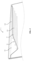
vehicle window assembly 1 applicable to a vehiclewindow glass sheet 12. Referring toFIGs. 1 and2 together,FIG. 1 is a schematic diagram of the vehicle window assembly according to an embodiment of the disclosure, andFIG. 2 is a schematic cross-sectional view taken along line I-I inFIG. 1 . Thevehicle window assembly 1 includes multiplelight guide strips 11 spaced apart from each other, the vehiclewindow glass sheet 12, and asealing box 13. The multiplelight guide strips 11 are arranged on one side surface of the vehiclewindow glass sheet 12. Thesealing box 13 is disposed at one side of each of the multiplelight guide strips 11 away from the vehiclewindow glass sheet 12. Thesealing box 13 definesgrooves 131 at positions respectively corresponding to the multiplelight guide strips 11, and each of the multiplelight guide strips 11 is received in one of thegrooves 131. - It should be noted that the
light guide strip 11 can guide light incident on an interface of thelight guide strip 11 to the entirelight guide strip 11, thereby achieving illumination of thelight guide strip 11 when exposed to light. Generally, the material of an inner side wall of thelight guide strip 11 has high light reflectivity, so that the light is not subject to excessive lost during transmission in thelight guide strip 11, thereby allowing the light to be transmitted in the entirelight guide strip 11. - In the embodiments, as shown in
FIG. 2 , thevehicle window assembly 1 further includesfixing members 14. Each of thefixing members 14 is configured to fix thesealing box 13 to the vehiclewindow glass sheet 12. For a better visual effect, the multiplelight guide strips 11 are arranged in parallel, and at the same time, in order to avoid affecting a visible range of the vehiclewindow glass sheet 12, the multiplelight guide strips 11 are arranged adjacent to a periphery of the vehicle window glass sheet 12 (for example, an upper edge, a lower edge, a left edge, or a right edge of the vehicle window glass sheet 12). In other possible embodiments, the multiplelight guide strips 11 may also be arranged to overlap or arranged at a certain angle to one another, which is not limited in the disclosure. - The
grooves 131 defined in thesealing box 13 form a certain accommodation space for accommodating thelight guide strips 11. Generally, a shape of thegroove 131 matches a shape of thelight guide strip 11. In other words, thelight guide strip 11 abuts against thegroove 131, thereby preventing thelight guide strip 11 from deviating in thegroove 131. Then, thesealing box 13 and the light guide strips 11 are fixed to the vehiclewindow glass sheet 12 by the fixingmembers 14. - It can be understood that, in the embodiments, the light guide strips 11 are accommodated in the
sealing box 13, and thesealing box 13 is directly fixed to the vehiclewindow glass sheet 12 by the fixingmembers 14, thereby eliminating the need for defining a hole in thevehicle window assembly 1, thereby ensuring sealing performance, optical performance, and the like of thevehicle window assembly 1, and reducing technical costs. - In a possible embodiment, referring to
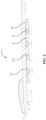
FIG. 3, FIG. 3 is a schematic diagram of a vehicle window assembly according to another embodiment of the disclosure. Thevehicle window assembly 1 further includes abright strip 15 and multiple light-emittingmodules 16. Thebright strip 15 and thesealing box 13 are opposite to each other to form a gap for accommodating the vehiclewindow glass sheet 12. Each of the multiple light-emittingmodules 16 is arranged within an orthographic projection of thebright strip 15 on the vehiclewindow glass sheet 12, and each of the multiple light-emittingmodules 16 defines a light-exiting opening, and a light ray exiting from the light-exiting opening corresponds to one the multiple light guide strips 11. - It should be noted that, in order to more clearly illustrate an arrangement relationship of various components of the
vehicle window assembly 1 under thebright strip 15 and the vehiclewindow glass sheet 12, various components of thevehicle window assembly 1 are illustrated in the figures in a perspective manner, which does not mean that the various components of thevehicle window assembly 1 can be directly observed from a schematic diagram of the vehiclewindow glass sheet 12. - When the gap between the
bright strip 15 and thesealing box 13 is configured to receive the vehiclewindow glass sheet 12, thebright strip 15 and thesealing box 13 are disposed on two opposite sides of the vehiclewindow glass sheet 12. - In the embodiments, the
bright strip 15 is made of opaque stainless steel and formed through stamping, and the light-emittingmodules 16 are arranged within an orthographic projection of thebright strip 15 on the vehiclewindow glass sheet 12. In other words, the light-emittingmodule 16 is disposed under thebright strip 15, so that during operation of the light-emittingmodule 16, light emitted from the light-emittingmodule 16 is unlikely to leak from under thebright strip 15. The light-emittingmodule 16 may be fixed to thebright strip 15 through the fixingmember 14 or may be integrally formed with thebright strip 15, as long as it does not affect that the light ray exiting from the light-exiting opening corresponds to at least one of the light guide strips 11, which is not limited in the disclosure. - Specifically, in the embodiments, the light ray that is emitted by each light-emitting
module 16 and exits from the light-exiting opening corresponds to onelight guide strip 11. In other possible embodiments, the light ray that is emitted from a single light-emittingmodule 16 and exits from the light-exiting opening may correspond to two light guide strips 11, three light guide strips 11, four light guide strips 11, or the like, which is not limited in the disclosure. The light incident into the light guide strips 11 is reflected by an inner side wall of thelight guide strip 11 to the entire light guide strips 11, thereby achieving the illumination of the entirelight guide strip 11. - In a possible embodiment, referring to
FIG. 3 , thebright strip 15 includes a firstbright portion 151 and a secondbright portion 152. The multiple light-emittingmodules 16 are arranged on the firstbright portion 151. The firstbright portion 151 is connected to the secondbright portion 152. The firstbright portion 151 and the secondbright portion 152 surround a space to define anaccommodating region 153, and the multiple light guide strips 11 are arranged within theaccommodating region 153. - Specifically, in the embodiments, an orthographic projection of the
light guide strip 11 on the vehiclewindow glass sheet 12 extends from an orthographic projection of the firstbright portion 151 on the vehiclewindow glass sheet 12. In other words, light transmitted from thelight guide strip 11 will not be blocked by thebright strip 15. As shown inFIG. 3 , thelight guide strip 11 is parallel to an extending direction of the secondbright portion 152. Moreover, in the embodiments, each of the multiple light guide strips 11 has the same length as each of the other of the multiple light guide strips 11, and a position of the firstbright portion 151 through which each of the multiple light guide strips 11 extends is different from a position of the firstbright portion 151 through which each of the other of the multiple light guide strips 11 extends, thus a certain sense of layering is achieved, thereby improving the aesthetic level of thevehicle window assembly 1, and avoiding affecting the visual range of the vehiclewindow glass sheet 12. - In other possible embodiments, the
light guide strip 11 may also be disposed at an angle to the secondbright portion 152. For example, an included angle between thelight guide strip 11 and the secondbright portion 152 is within a range of ±10 degrees, which is not limited in the disclosure. - In a possible embodiment, each of the multiple light-emitting
modules 16 is configured to emit a light ray having a light intensity and color different from a light intensity and color of a light ray emitted by each of the other of the multiple light-emitting modules. - Specifically, each of the multiple light-emitting
modules 16 may emit a light ray different from a color of a light ray emitted by each of the other of the multiple light-emittingmodules 16 under the control of an on-board processor, or alternatively, under the control of an electrical signal received from an electronic device, which is not limited in the disclosure. It can be understood that a light rat generally has multiple different parameters, which may be light intensity, color, and the like in visual experience. By providing different numbers of the light-emittingmodules 16 and the light guide strips 11, various combinations of different light intensities and colors can be achieved. For example, in the embodiments, four light-emittingmodules 16 and four light guide strips 11 are provided, so that a red light ray, a green light ray, a blue light ray, and a yellow light ray can be respectively emitted by the four light-emittingmodules 16 in the order in which the four light guide strips 11 are arranged, or a red light ray, a green light ray, a red light ray, and a green light ray can be respectively emitted by the four light-emittingmodules 16 in the order in which the four light guide strips 11 are arranged, which is not limited in the disclosure. - It should be noted that, due to the extended transmission capability of red light within the visible spectrum, in the related art, a vehicle headlight and a vehicle taillight in a driving direction of a vehicle are typically configured to emit red light to show front and rear contours of the vehicle. However, a side contour of the vehicle cannot be shown, and there is a certain driving risk. It can be understood that, in the embodiments, the light guide strips 11 are arranged in the
vehicle window assembly 1 of the vehiclewindow glass sheet 12 that is disposed on a side of the vehicle in the driving direction of the vehicle, thus red light can be transmitted through the light guide strips 11 to show a side contour of the vehicle in the driving direction of the vehicle, thereby further reducing a driving risk. - In a possible embodiment, referring to
FIG. 4, FIG. 4 is a schematic cross-sectional view of a vehicle window assembly according to an embodiment of the disclosure. Thevehicle window assembly 1 further includes multiple shielding members 17 spaced apart from each other and multiple light-transmitting films 18 spaced apart from each other. Each of the multiple shielding members 17 is adjacent to and connected to one of the multiple light-transmitting films 18. An orthographic projection of each of the multiple light-transmitting film 18 on the vehiclewindow glass sheet 12 covers an orthographic projection of a correspondinglight guide strip 11 on the vehiclewindow glass sheet 12, and a combination of an orthographic projection of each of the multiple shielding members 17 on the vehiclewindow glass sheet 12 and an orthographic projection of each of the multiple light-transmitting films 18 on the vehiclewindow glass sheet 12 covers an orthographic projection of thesealing box 13 on the vehiclewindow glass sheet 12. - It should be noted that, generally, the vehicle
window glass sheet 12 is of a sandwich design, and in order to shield part of components from being visible, the vehiclewindow glass sheet 12 is further provided with the shielding member 17 for shielding. In the embodiments, in order to allow a light ray from the light guide strips 11 to be normally irradiated out through the vehiclewindow glass sheet 12, a hollow design is defined in part of the shielding member 17 corresponding to the light guide strips 11. At the same time, the light-transmitting films 18 are provided on portions corresponding to the light guide strips 11, so that the light ray from the light guide strips 11 can be irradiated out through the light-transmitting film 18. - In the embodiments, the shielding member 17 and the light-transmitting film 18 are disposed on a side surface of the vehicle
window glass sheet 12 close to thelight guide strip 11. In other possible embodiments, the shielding member 17 and the light-transmitting film 18 may also be disposed at other positions of the vehiclewindow glass sheet 12, which is not limited in the disclosure. - In a possible embodiment, the light-transmitting film 18 is configured to allow a light ray to pass through unidirectionally.
- Specifically, in order to prevent the light guide strips 11 from being visible through the vehicle
window glass sheet 12, the light-transmitting film 18 is configured to allow a light ray to pass through unidirectionally. In other words, in the embodiments, the light-transmitting film 18 is configured to allow a light ray to pass through only in the same as a direction of the light ray from the light guide strip, as indicated by the arrow inFIG. 4 . When the light guide strips 11 transmit light, light transmitted by the light guide strips 11 is visible viewed from a side of the vehiclewindow glass sheet 12 away from the light guide strips 11. When thelight guide strip 11 does not transmit light, the light guide strips 11 is invisible viewed from the side of the vehiclewindow glass sheet 12 away from thelight guide strip 11. As can be appreciated, this arrangement enhances the aesthetic design of thevehicle window assembly 1. - Specifically, as shown in
FIG. 4 , the light-transmitting film 18 covers the orthographic projection of thelight guide strip 11 on the vehiclewindow glass sheet 12, so that thelight guide strip 11 is invisible when thelight guide strip 11 does not transmit light. In other possible embodiments, the light guide strips 11 may also be made invisible in other manners, for example, thelight guide strip 11 is made from a material approximate to glass in appearance, which is not limited in the disclosure. In a possible embodiment, referring toFIGs. 5 and6 together,FIG. 5 is a schematic cross-sectional view of a vehicle window assembly according to another embodiment of the disclosure, andFIG. 6 is a schematic cross-sectional view of a vehicle window assembly according to another embodiment of the disclosure. Thesealing box 13 is integrally formed by injection molding. Each of thegrooves 131 has a semicircular shape, a rectangular shape, or a trapezoidal shape, or thegrooves 131 include various types of grooves among a semicircular groove, a rectangular groove, and a trapezoidal groove. - Specifically, the
sealing box 13 is integrally formed by injection molding, so that thesealing box 13 has good sealing performance and optical performance. When thelight guide strip 11 accommodated in thegroove 131 transmits light, the light is unlikely to leak from thesealing box 13. - It should be noted that, the shape of the
groove 131 refers to a shape of a cross-section of thegroove 131 in a cross-sectional view. As shown inFIG. 2 , the shape of thegroove 131 is a semicircle. As shown inFIG. 5 , the shape of thegroove 131 is a rectangle. As shown inFIG. 6 , the shape of thegroove 131 is a trapezoid. It can be understood that, the shape of thegroove 131 is not limited in the disclosure as long as the deviation does not occur to the light guide strips 11 accommodated in thegroove 131. - In a possible embodiment, each of the fixing
members 14 is an optical adhesive, a 3M™ adhesive, or a polyurethane adhesive, or the fixingmembers 14 include various types of fixing members among the optical adhesive, the 3M™ adhesive, and the polyurethane adhesive. - Specifically, because the vehicle
window glass sheet 12 is easy to fracture, the fixingmember 14 is generally an adhesive, such as optical adhesive, a 3M™ adhesive, a polyurethane adhesive, or the like. In other possible embodiments, the fixingmember 14 may also be an adhesive tape or a snap-fitting structure, which is not limited in the disclosure as long as the fixingmember 14 does not bring damage to the vehiclewindow glass sheet 12. - In a possible embodiment, referring to
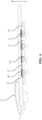
FIG. 7, FIG. 7 is a schematic diagram of a vehicle window assembly according to another embodiment of the disclosure. Thevehicle window assembly 1 includes a hemmingstrip 19. The hemmingstrip 19 is separated from thelight guide strip 11 and is configured to fix the vehiclewindow glass sheet 12. - Specifically, for the
vehicle window assembly 1, reference may be made to the foregoing description, and details are not described herein again. The hemmingstrip 19 is generally made of a rubber, thus when the vehiclewindow glass sheet 12 is fixed, it is not easy to damage the vehiclewindow glass sheet 12, and at the same time, good sealing performance is achieved. When the vehiclewindow glass sheet 12 is fixed on a frame through the hemmingstrip 19, it is not easy to break the sealing performance of the vehicle. - It should be noted that the hemming
strip 19 is separated from thelight guide strip 11. In other words, the hemmingstrip 19 is not integrally formed with thelight guide strip 11, and a mold of the hemmingstrip 19 can be designed separately from a mold of thelight guide strip 11. - In a possible embodiment, the
vehicle window assembly 1 further includes abright strip 15. The hemmingstrip 19 and thebright strip 15 cooperate to fix thevehicle window assembly 1 to the hemmingstrip 19. - Specifically, in the embodiments, the
bright strip 15 is made of stainless steel and is formed through stamping, a snap-fitting part is arranged at a part of thebright strip 15 corresponding to the hemmingstrip 19, and thebright strip 15 is snap-fitted with the hemmingstrip 19 through the snap-fitting part, so that thevehicle window assembly 1 is fixed to the hemmingstrip 19. In other possible embodiments, the manner in which thevehicle window assembly 1 is fixed to the hemmingstrip 19 is not limited in the disclosure. - It can be understood that, in the embodiments, the
vehicle window assembly 1 is independent from the hemmingstrip 19, and when a mold of thevehicle window assembly 1 or a mold of the hemmingstrip 19 may be changed subsequently, a mold of one of thevehicle window assembly 1 and the hemmingstrip 19 can be changed without affecting the other, thereby reducing the technical costs. - The disclosure also provides a
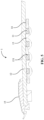
vehicle 2. Referring toFIG. 8, FIG. 8 is a schematic top view of a vehicle according to an embodiment of the disclosure. Thevehicle 2 includes aframe 21 and thevehicle window assembly 1 as described above, and the vehiclewindow glass sheet 12 is fixed to theframe 21 through the hemmingstrip 19. Specifically, for thevehicle window assembly 1, reference may be made to the foregoing illustration, and details are not repeatedly described herein. - Specific examples are applied here to set forth the principle and the embodiments of the disclosure, and the foregoing illustration of the embodiments is only to help in understanding the core idea of the disclosure. Meanwhile, those of ordinarily skill in the art may make variations and modifications to the disclosure in terms of the specific embodiments and application scopes according to the ideas of the disclosure. Therefore, the specification shall not be construed as limitations to the disclosure.
Claims (11)
- A vehicle window assembly, comprising a plurality of light guide strips spaced apart from each other, a vehicle window glass sheet, and a sealing box, wherein the plurality of light guide strips are arranged on one side surface of the vehicle window glass sheet, the sealing box is disposed at one side of each of the plurality of light guide strips away from the vehicle window glass sheet, the sealing box defines grooves at positions respectively corresponding to the plurality of light guide strips, and each of the plurality of light guide strips is received in one of the grooves.
- The vehicle window assembly of claim 1, further comprising a bright strip and a plurality of light-emitting modules, wherein the bright strip and the sealing box are opposite to each other to define a gap for accommodating the vehicle window glass sheet, wherein each of the plurality of light-emitting modules is arranged within an orthographic projection of the bright strip on the vehicle window glass sheet, each of the plurality of light-emitting modules defines a light-exiting opening, and a light ray exiting from the light-exiting opening corresponds to at least one of the plurality of light guide strips.
- The vehicle window assembly of claim 2, wherein the bright strip comprises a first bright portion and a second bright portion, wherein the plurality of light-emitting modules are arranged on the first bright portion, the second bright portion is connected to the first bright portion, the first bright portion and the second bright portion surround a space to define an accommodating region, and the plurality of light guide strips are arranged within the accommodating region.
- The vehicle window assembly of claim 2, wherein each of the plurality of light-emitting modules is configured to emit a light ray having a light intensity and color different from a light intensity and color of a light ray emitted by each of the other of the plurality of light-emitting modules.
- The vehicle window assembly of claim 1, further comprising a plurality of shielding members spaced apart from each other and a plurality of light-transmitting films spaced apart from each other, each of the plurality of shielding members is adjacent to and connected to one of the plurality of light-transmitting films, an orthographic projection of each of the plurality of light-transmitting films on the vehicle window glass sheet covers an orthographic projection of a corresponding light guide strip on the vehicle window glass sheet, and a combination of an orthographic projection of each of the plurality of shielding members on the vehicle window glass sheet and an orthographic projection of each of the plurality of light-transmitting films on the vehicle window glass sheet covers an orthographic projection of the sealing box on the vehicle window glass sheet.
- The vehicle window assembly of claim 5, wherein each of the plurality of light-transmitting films is configured to allow a light ray to pass through unidirectionally.
- The vehicle window assembly of claim 1, wherein the sealing box is integrally formed by injection molding; and each of the grooves has a semicircular shape, a rectangular shape, or a trapezoidal shape, or the grooves comprise various types of grooves among a semicircular groove, a rectangular groove, and a trapezoidal groove.
- The vehicle window assembly of claim 1, further comprising fixing members, wherein each of the fixing members is configured to fix the sealing box to the vehicle window glass sheet; and each of the fixing members is an optical adhesive, a 3M™ adhesive, or a polyurethane adhesive, or the fixing members comprise various types of fixing members among the optical adhesive, the 3M™ adhesive, and the polyurethane adhesive.
- The vehicle window assembly of claim 1, further comprising a hemming strip, wherein the hemming strip is separated from the light guide strip and is configured to fix the vehicle window glass sheet.
- The vehicle window assembly of claim 9, wherein the vehicle window assembly further comprises a bright strip, and the hemming strip and the bright strip cooperate to fix the vehicle window assembly to the hemming strip.
- A vehicle, comprising a frame and the vehicle window assembly of any one of claims 1 to 10, the vehicle window assembly being mounted to the frame.
Applications Claiming Priority (2)
| Application Number | Priority Date | Filing Date | Title |
|---|---|---|---|
| CN202110570803.0A CN113232496B (en) | 2021-05-25 | 2021-05-25 | Vehicle window assembly and vehicle |
| PCT/CN2022/080954 WO2022247401A1 (en) | 2021-05-25 | 2022-03-15 | Vehicle window assembly and vehicle |
Publications (3)
| Publication Number | Publication Date |
|---|---|
| EP4309934A1 true EP4309934A1 (en) | 2024-01-24 |
| EP4309934A4 EP4309934A4 (en) | 2024-08-28 |
| EP4309934B1 EP4309934B1 (en) | 2026-01-14 |
Family
ID=77138717
Family Applications (1)
| Application Number | Title | Priority Date | Filing Date |
|---|---|---|---|
| EP22810135.8A Active EP4309934B1 (en) | 2021-05-25 | 2022-03-15 | Vehicle window assembly and vehicle |
Country Status (6)
| Country | Link |
|---|---|
| US (1) | US12351106B2 (en) |
| EP (1) | EP4309934B1 (en) |
| JP (1) | JP7639175B2 (en) |
| KR (1) | KR102885524B1 (en) |
| CN (1) | CN113232496B (en) |
| WO (1) | WO2022247401A1 (en) |
Families Citing this family (2)
| Publication number | Priority date | Publication date | Assignee | Title |
|---|---|---|---|---|
| CN113232496B (en) * | 2021-05-25 | 2022-07-19 | 福耀玻璃工业集团股份有限公司 | Vehicle window assembly and vehicle |
| CN118182314B (en) * | 2024-03-08 | 2025-11-11 | 福耀玻璃工业集团股份有限公司 | Vehicle window glass assembly with luminous component, manufacturing method thereof and vehicle |
Family Cites Families (31)
| Publication number | Priority date | Publication date | Assignee | Title |
|---|---|---|---|---|
| US6327954B1 (en) * | 1993-06-03 | 2001-12-11 | Richard C. Medlin | Lightweight armored vehicle and method of making same |
| JPH10147177A (en) * | 1996-11-15 | 1998-06-02 | Toyota Autom Loom Works Ltd | Mounting structure of high mount stop lamp and back window glass |
| DE19818153B4 (en) * | 1998-04-23 | 2006-08-10 | Richard Fritz Gmbh + Co. Kg | Disk unit for installation in a predetermined opening of motor vehicles and the like |
| DE10320614B4 (en) * | 2003-05-08 | 2006-01-12 | Webasto Ag | Cover for an opening in a vehicle roof and manufacturing method therefor |
| DE102007013627A1 (en) * | 2007-03-19 | 2008-09-25 | Hella Kgaa Hueck & Co. | Interior light for vehicle, has illuminant which is connected with power supply connection by control unit and laminar light conductor is arranged in light path of optical radiation |
| FR2955530B1 (en) * | 2010-01-26 | 2015-11-20 | Saint Gobain | LUMINOUS VEHICLE GLAZING, MANUFACTURING |
| JP2012077604A (en) | 2010-09-09 | 2012-04-19 | Yukio Nishimura | Planar body including light guide light emitting element |
| DE102011106595B4 (en) * | 2011-06-16 | 2026-01-15 | Volkswagen Aktiengesellschaft | Arrangement of a lighting device in a vehicle and method for manufacturing an external surface element of a vehicle |
| JP5774942B2 (en) * | 2011-08-26 | 2015-09-09 | 日立マクセル株式会社 | Illumination unit and display device using the same |
| JP6134484B2 (en) * | 2012-06-29 | 2017-05-24 | 株式会社小糸製作所 | Vehicle rear panel |
| CN102785555B (en) * | 2012-07-11 | 2015-08-05 | 法国圣戈班玻璃公司 | Skylight glass, lighting apparatus for vehicle and room light method |
| FR3001674B1 (en) * | 2013-02-01 | 2016-01-01 | Peugeot Citroen Automobiles Sa | VEHICLE EQUIPPED WITH A LIGHTING DEVICE REPORTED UNDER THE INTERNAL PART OF THE ROOF OF THE VEHICLE |
| CN103754170B (en) * | 2014-01-07 | 2016-05-18 | 福耀玻璃工业集团股份有限公司 | Inserts and windowpane in the middle of a kind of |
| JP6194513B2 (en) | 2014-06-19 | 2017-09-13 | 豊田合成株式会社 | Waterproof structure for vehicular lamp |
| US20180052272A1 (en) * | 2015-03-17 | 2018-02-22 | Philips Lighting Holding B.V. | Light spreading in textiles |
| FR3040992B1 (en) * | 2015-09-11 | 2017-10-06 | Saint Gobain | LUMINOUS GLAZING OF VEHICLE AND ITS MANUFACTURE. |
| WO2017120283A1 (en) * | 2016-01-05 | 2017-07-13 | Corning Incorporated | Laminated light diffusing optical fiber |
| DE102016218755B3 (en) * | 2016-09-28 | 2017-11-23 | Süddeutsche Aluminium Manufaktur GmbH | Window channel strip arrangement |
| SI25295A (en) | 2016-10-14 | 2018-04-30 | Hella Saturnus Slovenija d.o.o. | Additional motor vehicle brake light |
| JP6900772B2 (en) * | 2017-05-10 | 2021-07-07 | 大日本印刷株式会社 | Lighting equipment and vehicles |
| DE202017106805U1 (en) * | 2017-11-09 | 2019-02-12 | lnalfa Roof Systems Group B.V. | Open roof construction for a vehicle |
| CN207825900U (en) * | 2017-11-27 | 2018-09-07 | 长城汽车股份有限公司 | Sealing strip and automobile |
| FR3084296B1 (en) * | 2018-07-25 | 2020-07-03 | Renault S.A.S. | MOTOR VEHICLE DOOR COMPRISING A LIGHT SOURCE CARRIED BY AN INNER SEAL |
| CN208730861U (en) * | 2018-08-02 | 2019-04-12 | 爱信(南通)汽车技术中心有限公司 | Skylight device with ornament lamp |
| KR20200021567A (en) * | 2018-08-20 | 2020-03-02 | 희성전자 주식회사 | Sunroof window for vehicle |
| FR3087726B1 (en) | 2018-10-31 | 2022-09-09 | Saint Gobain | LUMINOUS GLAZING FOR MOTOR VEHICLES |
| DE202020005400U1 (en) * | 2019-01-29 | 2021-01-29 | Schott Ag | Line light |
| CN211574858U (en) * | 2019-12-30 | 2020-09-25 | 麦格纳(太仓)汽车科技有限公司 | Installation structure of light guide LED ambient light for automobile sunroof |
| DE102020109338B3 (en) * | 2020-04-03 | 2021-05-27 | Webasto SE | Vehicle window with light source and light guide layer |
| CN111559310B (en) * | 2020-05-12 | 2021-08-10 | 福耀玻璃工业集团股份有限公司 | Light source module for skylight atmosphere lamp |
| CN113232496B (en) * | 2021-05-25 | 2022-07-19 | 福耀玻璃工业集团股份有限公司 | Vehicle window assembly and vehicle |
-
2021
- 2021-05-25 CN CN202110570803.0A patent/CN113232496B/en active Active
-
2022
- 2022-03-15 KR KR1020237036977A patent/KR102885524B1/en active Active
- 2022-03-15 EP EP22810135.8A patent/EP4309934B1/en active Active
- 2022-03-15 WO PCT/CN2022/080954 patent/WO2022247401A1/en not_active Ceased
- 2022-03-15 JP JP2023565323A patent/JP7639175B2/en active Active
-
2023
- 2023-11-14 US US18/508,457 patent/US12351106B2/en active Active
Also Published As
| Publication number | Publication date |
|---|---|
| JP2024514965A (en) | 2024-04-03 |
| US20240083352A1 (en) | 2024-03-14 |
| CN113232496A (en) | 2021-08-10 |
| EP4309934A4 (en) | 2024-08-28 |
| KR20230162675A (en) | 2023-11-28 |
| CN113232496B (en) | 2022-07-19 |
| WO2022247401A1 (en) | 2022-12-01 |
| US12351106B2 (en) | 2025-07-08 |
| EP4309934B1 (en) | 2026-01-14 |
| JP7639175B2 (en) | 2025-03-04 |
| KR102885524B1 (en) | 2025-11-12 |
Similar Documents
| Publication | Publication Date | Title |
|---|---|---|
| US12351106B2 (en) | Vehicle window assembly with plurality of light guide strips and vehicle having the same | |
| US20140003076A1 (en) | Vehicular lamp and window unit | |
| US20120051077A1 (en) | Vehicular lamp | |
| EP2353937A1 (en) | Vehicle lamp | |
| US11453341B2 (en) | Vehicle mirror device and illuminatable mirror display device | |
| US11293621B2 (en) | Light guide for lamps and related lamp for motor vehicles | |
| US7213956B2 (en) | Light correction member, light diffusion member, display member, and display using the same | |
| CN114034020B (en) | Light assembly and display device | |
| GB2585688A (en) | Vehicle lamps | |
| US20150175066A1 (en) | Lighting apparatus of clock for vehicle | |
| JP4733064B2 (en) | Vehicle lamp | |
| CN110715258B (en) | Light guide | |
| EP4434782A1 (en) | Automobile window and automobile | |
| CN221402824U (en) | Optical system for end light-entering type ultra-thin stereoscopic effect atmosphere lamp | |
| JP2014142603A (en) | Display device | |
| KR101915137B1 (en) | Light guide and dimming display | |
| US11377035B2 (en) | BSM unit | |
| CN219756115U (en) | Shan Ceru light elongate light-guiding atmosphere lamp | |
| CN114604187A (en) | Automobile trim board assembly and automobile | |
| JPS581816Y2 (en) | multiple display device | |
| EP4667286A1 (en) | Side turn signal lamp mounting assembly, door body of vehicle, and vehicle | |
| CN216897028U (en) | Side direction luminous ceiling lamp | |
| WO2025157658A1 (en) | Lighting assembly and motor vehicle | |
| CN224075503U (en) | Car logo structure and vehicle | |
| CN223377572U (en) | Display device and HUD device having the same |
Legal Events
| Date | Code | Title | Description |
|---|---|---|---|
| STAA | Information on the status of an ep patent application or granted ep patent |
Free format text: STATUS: THE INTERNATIONAL PUBLICATION HAS BEEN MADE |
|
| PUAI | Public reference made under article 153(3) epc to a published international application that has entered the european phase |
Free format text: ORIGINAL CODE: 0009012 |
|
| STAA | Information on the status of an ep patent application or granted ep patent |
Free format text: STATUS: REQUEST FOR EXAMINATION WAS MADE |
|
| 17P | Request for examination filed |
Effective date: 20231020 |
|
| AK | Designated contracting states |
Kind code of ref document: A1 Designated state(s): AL AT BE BG CH CY CZ DE DK EE ES FI FR GB GR HR HU IE IS IT LI LT LU LV MC MK MT NL NO PL PT RO RS SE SI SK SM TR |
|
| A4 | Supplementary search report drawn up and despatched |
Effective date: 20240725 |
|
| DAV | Request for validation of the european patent (deleted) | ||
| DAX | Request for extension of the european patent (deleted) | ||
| RIC1 | Information provided on ipc code assigned before grant |
Ipc: B60Q 3/62 20170101ALI20240719BHEP Ipc: B60J 10/265 20160101ALI20240719BHEP Ipc: B60Q 3/208 20170101ALI20240719BHEP Ipc: B60J 10/70 20160101AFI20240719BHEP |
|
| STAA | Information on the status of an ep patent application or granted ep patent |
Free format text: STATUS: EXAMINATION IS IN PROGRESS |
|
| 17Q | First examination report despatched |
Effective date: 20250417 |
|
| GRAP | Despatch of communication of intention to grant a patent |
Free format text: ORIGINAL CODE: EPIDOSNIGR1 |
|
| STAA | Information on the status of an ep patent application or granted ep patent |
Free format text: STATUS: GRANT OF PATENT IS INTENDED |
|
| INTG | Intention to grant announced |
Effective date: 20250925 |
|
| GRAS | Grant fee paid |
Free format text: ORIGINAL CODE: EPIDOSNIGR3 |
|
| GRAA | (expected) grant |
Free format text: ORIGINAL CODE: 0009210 |
|
| STAA | Information on the status of an ep patent application or granted ep patent |
Free format text: STATUS: THE PATENT HAS BEEN GRANTED |
|
| AK | Designated contracting states |
Kind code of ref document: B1 Designated state(s): AL AT BE BG CH CY CZ DE DK EE ES FI FR GB GR HR HU IE IS IT LI LT LU LV MC MK MT NL NO PL PT RO RS SE SI SK SM TR |
|
| REG | Reference to a national code |
Ref country code: CH Ref legal event code: F10 Free format text: ST27 STATUS EVENT CODE: U-0-0-F10-F00 (AS PROVIDED BY THE NATIONAL OFFICE) Effective date: 20260114 Ref country code: GB Ref legal event code: FG4D |
|
| REG | Reference to a national code |
Ref country code: DE Ref legal event code: R096 Ref document number: 602022028537 Country of ref document: DE |
|
| REG | Reference to a national code |
Ref country code: IE Ref legal event code: FG4D |
|
| P01 | Opt-out of the competence of the unified patent court (upc) registered |
Free format text: CASE NUMBER: UPC_APP_0000978_4309934/2026 Effective date: 20260112 |
|
| PGFP | Annual fee paid to national office [announced via postgrant information from national office to epo] |
Ref country code: GB Payment date: 20260325 Year of fee payment: 5 |
|
| PGFP | Annual fee paid to national office [announced via postgrant information from national office to epo] |
Ref country code: DE Payment date: 20260324 Year of fee payment: 5 |
|
| PGFP | Annual fee paid to national office [announced via postgrant information from national office to epo] |
Ref country code: AT Payment date: 20260301 Year of fee payment: 5 |
|
| PGFP | Annual fee paid to national office [announced via postgrant information from national office to epo] |
Ref country code: FR Payment date: 20260330 Year of fee payment: 5 |