EP4309810A1 - Foreign matter removal device - Google Patents
Foreign matter removal device Download PDFInfo
- Publication number
- EP4309810A1 EP4309810A1 EP22865114.7A EP22865114A EP4309810A1 EP 4309810 A1 EP4309810 A1 EP 4309810A1 EP 22865114 A EP22865114 A EP 22865114A EP 4309810 A1 EP4309810 A1 EP 4309810A1
- Authority
- EP
- European Patent Office
- Prior art keywords
- electrode
- unit
- foreign matter
- removal device
- matter removal
- Prior art date
- Legal status (The legal status is an assumption and is not a legal conclusion. Google has not performed a legal analysis and makes no representation as to the accuracy of the status listed.)
- Granted
Links
Images



Classifications
-
- B—PERFORMING OPERATIONS; TRANSPORTING
- B08—CLEANING
- B08B—CLEANING IN GENERAL; PREVENTION OF FOULING IN GENERAL
- B08B5/00—Cleaning by methods involving the use of air flow or gas flow
- B08B5/02—Cleaning by the force of jets, e.g. blowing-out cavities
- B08B5/023—Cleaning travelling work
-
- B—PERFORMING OPERATIONS; TRANSPORTING
- B08—CLEANING
- B08B—CLEANING IN GENERAL; PREVENTION OF FOULING IN GENERAL
- B08B5/00—Cleaning by methods involving the use of air flow or gas flow
- B08B5/04—Cleaning by suction, with or without auxiliary action
- B08B5/043—Cleaning travelling work
-
- H—ELECTRICITY
- H01—ELECTRIC ELEMENTS
- H01M—PROCESSES OR MEANS, e.g. BATTERIES, FOR THE DIRECT CONVERSION OF CHEMICAL ENERGY INTO ELECTRICAL ENERGY
- H01M10/00—Secondary cells; Manufacture thereof
- H01M10/04—Construction or manufacture in general
-
- Y—GENERAL TAGGING OF NEW TECHNOLOGICAL DEVELOPMENTS; GENERAL TAGGING OF CROSS-SECTIONAL TECHNOLOGIES SPANNING OVER SEVERAL SECTIONS OF THE IPC; TECHNICAL SUBJECTS COVERED BY FORMER USPC CROSS-REFERENCE ART COLLECTIONS [XRACs] AND DIGESTS
- Y02—TECHNOLOGIES OR APPLICATIONS FOR MITIGATION OR ADAPTATION AGAINST CLIMATE CHANGE
- Y02E—REDUCTION OF GREENHOUSE GAS [GHG] EMISSIONS, RELATED TO ENERGY GENERATION, TRANSMISSION OR DISTRIBUTION
- Y02E60/00—Enabling technologies; Technologies with a potential or indirect contribution to GHG emissions mitigation
- Y02E60/10—Energy storage using batteries
-
- Y—GENERAL TAGGING OF NEW TECHNOLOGICAL DEVELOPMENTS; GENERAL TAGGING OF CROSS-SECTIONAL TECHNOLOGIES SPANNING OVER SEVERAL SECTIONS OF THE IPC; TECHNICAL SUBJECTS COVERED BY FORMER USPC CROSS-REFERENCE ART COLLECTIONS [XRACs] AND DIGESTS
- Y02—TECHNOLOGIES OR APPLICATIONS FOR MITIGATION OR ADAPTATION AGAINST CLIMATE CHANGE
- Y02P—CLIMATE CHANGE MITIGATION TECHNOLOGIES IN THE PRODUCTION OR PROCESSING OF GOODS
- Y02P70/00—Climate change mitigation technologies in the production process for final industrial or consumer products
- Y02P70/50—Manufacturing or production processes characterised by the final manufactured product
Definitions
- the present disclosure relates to a foreign matter removal device, and more particularly to a foreign matter removal device that removes foreign matters on the electrode surface in the production process of a battery.
- a secondary battery has attracted considerable attention as an energy source for power-driven devices, such as an electric bicycle, an electric vehicle, and a hybrid electric vehicle, as well as an energy source for mobile devices, such as a mobile phone, a digital camera, a laptop computer and a wearable device.
- the secondary battery may be classified based on the shape of a battery case into a cylindrical or prismatic battery wherein an electrode assembly having a structure in which a cathode, an anode, and a separator interposed between the cathode and the anode are stacked, is built in a cylindrical or prismatic metal can, and a pouch-type battery in which the electrode assembly is built in a pouch-shaped case made of a laminated aluminum sheet.
- the secondary battery may be classified based on the structure of an electrode assembly having a structure in which a cathode and an anode are stacked with a separator being interposed between the cathode and the anode.
- a jelly-roll (wound) type structure in which long sheet type cathodes and long sheet type anodes are rolled with a separator being interposed between the cathode and the anode
- a stacked (laminated) type structure in which pluralities of cathodes and anodes, cut into predetermined unit sizes, are sequentially stacked with separators being interposed between the cathodes and the anodes, or the like.
- a stacked/folded type electrode assembly which is a combination of the jelly-roll type electrode assembly and the stacked type electrode assembly.
- Such electrode assemblies may generally be combined or produced via semi-automated or automated production lines.
- the electrode, separator or the like constituting the electrode assembly is transferred along a guide member such as a rail or a rotating roll to a device that performs processing such as cuttings, adhesion, lamination and rolling, and can be combined or produced in the form of an electrode assembly through the operation of the above devices.
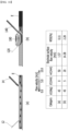
- Fig. 1 is a cross-sectional view showing a conventional foreign matter removal device.
- the foreign matter removal device 10 includes a blowing unit 12 that blows air toward the surface of the electrode E moving along the transport direction p1, and a suction unit 14 that sucks foreign matters separated from the electrode surface, through which foreign matters on the surface of the electrode E are removed.
- the air blown from the blowing unit 12 tends to be concentrated on the lower surface of the extension unit 16 between the blowing unit 12 and the suction unit 14 rather than the electrode E, due to the Coanda effect, which causes a problem that the foreign matter removal efficiency is lowered. Furthermore, if the flow rate/flow velocity is increased to solve these problems, the air consumption increased and the noise was generated.
- the present disclosure has been designed to solve the above-mentioned problems, and an object of the present disclosure is to provide a foreign matter removal device that can improve the foreign matter removal efficiency and minimize the product defect rate by concentrating the blown air on the surface of an electrode.
- a foreign matter removal device for removing foreign matters on the surface of an electrode that is continuously transferred along one direction, the device comprising: a blowing unit that blows air toward the electrode surface, a suction unit that sucks foreign matters separated from the electrode surface, and an extension unit extending between the blowing unit and the suction unit, wherein the extension unit is formed with an adjustment unit recessed in a direction away from the electrode surface.
- the blowing unit and the suction unit are formed of a slit forming an angle with the transfer direction of the electrode, the air blown from the blowing unit moves toward a direction opposite to the transfer direction of the electrode, and the air sucked by the suction unit may move in the same direction as the moving direction of the blown air.
- the angle that the blowing unit makes with the transport direction of the electrode may have a value of acute angle substantially equal to the angle that the suction unit makes with the transport direction of the electrode.
- the angle at which the air may be blown to the blowing unit forms 35 degrees to 55 degrees with the transfer direction of the electrode.
- the blowing unit is formed of a slit forming an angle with the transfer direction of the electrode, and a width of the slit may be 0.03 mm to 0.07 mm.
- the blowing unit is formed of a slit forming an angle with the transfer direction of the electrode, a protrusion protruding toward the flow space of the air is located at the end of the blowing unit, and the flow space may refer to a space formed above the electrode surface.
- the protrusion forms an angle with the transport direction of the electrode, and an angle at which the protrusion makes with the transfer direction of the electrode may correspond to an angle at which the blowing unit makes with the transfer direction of the electrode.
- a protrusion length of the protrusion may be 2 mm to 3 mm.
- An angle at which the suction unit sucks foreign matters may be 35 degrees to 55 degrees.
- the suction unit is formed of a slit forming an angle with the transfer direction of the electrode, and the width of the slit may be 1.0 mm to 3.0 mm.
- the length of the extension unit may be 20 mm to 35 mm.
- a depth of the adjustment unit is 3mm to 5mm, and the depth of the adjustment unit may be calculated based on one surface of the extension unit on which the adjustment unit is not formed.
- planar when referred to as “planar”, it means when a target portion is viewed from the upper side, and when referred to as “cross-sectional”, it means when a target portion is viewed from the side of a cross section cut vertically.
- the foreign matter removal device 100 described below is described focusing on that it is used to remove foreign matters on the surface of the electrode E in the production process of the secondary battery. However, this is not necessarily the case, and it is obvious that the device can be used in various processes that require removal of foreign matters on the surface in addition to the production process of the secondary battery.
- Fig. 2 is a cross-sectional view of a foreign matter removal device according to an embodiment of the present disclosure.
- the foreign matter removal device 100 has two body parts 110 symmetrical about the electrode E that crosses the center of the foreign matter removal device 100.
- the main body part 110 located on the upper part of the electrode E will be mainly described below, but it will be clarified in advance that these descriptions can also be applied to the main body part 110 located on the lower part of the electrode E.
- the foreign matter removal device 100 includes a blowing unit 120 that blows air toward the surface of the electrode E moving along the transport direction p1 between the two main body parts 110, a suction unit 140 that sucks foreign matters separated from the electrode surface, and an extension unit 160 extending between the blowing unit 120 and the suction unit 140, wherein the extension portion 160 is formed with an adjustment unit 180 having a recessed shape.
- the electrode E may be an object of the foreign material removal device 100.
- the electrode E may be provided in the form of a rectangular sheet in which the electrode slurry is applied to the current collector.
- the current collector that can be used here includes stainless steel, aluminum, copper, nickel, titanium, calcined carbon, or the like, and may be provided in various forms, such as a film, a sheet, a foil, a net, a porous body, a foam, and a nonwoven fabric.
- the electrode slurry may usually include an electrode active material, a conductive material, a binder, and a solvent, but is not limited thereto.
- the electrode E may be moved in one direction by the rotational force of a roller that winds or unwinds the electrode.
- the electrode E may be continuously moved by the rotational force of a roller that winds or unwinds the electrode.
- the roller allows the electrode E to move between the two main body parts 110 inside the foreign matter removal device 100.
- the blowing unit 120 can be configured to blow air to remove foreign matters attached to the surface of the electrode E.
- the blowing unit 120 may be located farther from the place where the electrode E inflows to pass through the foreign matter removal device 100 so that it faces the electrode E later than the suction unit 140 on the basis of the transport direction p1 of the electrode E in the foreign matter removal device 100.
- the blowing unit 120 may be formed in a slit shape in the main body part 110.
- the flow rate and flow velocity of the air injected from the blowing unit 120 may be determined according to the width of the slit of the blowing unit 120.
- the width of the slit of the blowing unit 120 according to the present embodiment may be smaller than the width of the slit of a normal blowing unit 120.
- the width of the slit of the blowing unit 120 may be less than 0.5 mm.
- the width of the slit of the blowing unit 120 may be 0.1mm or less, 0.07mm or less, and 0.01mm or more, 0.03mm or more.
- the error range may be 0.05 mm or less of 0.005 mm. This is to maximize the flow velocity at the same flow rate by making the width of the slit smaller than in the prior art.
- the blow angle a1 of the air discharged by the blowing unit 120 may form an angle with the transfer direction p1 of the electrode E.
- the blow angle a1 may be determined according to the shape of the slit of the blowing unit 120.
- the blow angle a1 may refer to an acute angle among the angles formed by the transport direction p1 of the electrode E and the air jetting path.
- the blowing unit 120 may be formed into an oblique line toward the surface of the electrode E inside the main body part 110.
- the blowing unit 120 may be formed in an oblique line so that the air outflowing from the blowing unit 120 moves in a direction opposite to the transfer direction p1 of the electrode. Since the pressure applied to the surface of the electrode E by the air ejected from the blowing unit 120 may be different depending on the blow angle a1 of the blowing unit 120, the blow angle a1 of the blowing unit 120 may have to be appropriately designed. A detailed description of the blow angle a1 will be described later through experimental data.
- a protrusion 122 may be formed at the end of the blowing unit 120.
- the protrusion 122 may refer to a portion that extends from the blowing unit 120 and protrudes into the air flow space.
- the 'flow space' means a space formed on the upper part of the surface of the electrode E, and may mean a space formed between the present foreign matter removal device 100 and the surface of the electrode E.
- the 'flow space' may be formed larger by the adjustment unit 180, wherein the 'flow space' may refer to a space between the surface of the recessed adjustment unit 180 and the surface of the electrode E.
- the protrusion 122 may be located at the end in the travelling direction of the air discharged from the blowing unit 120, thereby adjusting the flow direction of the blown air.
- the flow direction of the air may vary depending on the angle of the protrusion 122.
- the angle of the protrusion 122 may correspond to the blow angle a1 of the blowing unit 120.
- the blow angle a1 it would also be possible to design the blow angle a1 to be smaller or larger, depending on the intentions of the designer.
- the flow direction of the air may vary depending on the size of the protrusion 122. Depending on the degree to which the protrusion 122 protrudes into the air flow space, the effect of the protrusion 122 on the air may vary.
- the suction unit 140 may be configured to suck foreign matters separated from the surface of the electrode E by the blowing unit 120 and remove them.
- the suction unit 140 may be located close to a place where the electrode E inflows to pass through a portion of the foreign matter removal device 100 so as to meet the electrode E before the blowing unit 120 based on the transport direction p1 in the foreign matter removal device 100.
- the suction unit 140 may be formed in a slit shape in the main body part 110.
- the flow rate and flow velocity of the air sucked in by the suction unit 140 may be determined according to the width of the slit of the suction unit 140. It may be preferable that the suction unit 140 has a larger slit width than that of the blowing unit 120 in terms of its function.
- the width of the slit of the suction unit 140 may be 1.0 to 3.0 mm, and specifically, it may be 2.0 mm within an error range of 0.2 mm or less.
- An angle at which the suction unit 140 sucks air may form an angle with the transport direction p1 of the electrode E.
- the suction unit 140 may be formed into an oblique line from the surface of the electrode E toward the inside of the main body part 110.
- the suction unit 140 may be formed into an oblique line so that the sucked air is directed from the front to the rear with respect to the transport direction p1 of the electrode.
- the blow angle of the suction unit 140 may have to be appropriately designed.
- the jetting angle of the suction unit 140 may be 35 to 55 degrees, which may mean an acute angle formed with the transport direction p1 of the electrode E.
- the end of the blowing unit 120 and the end of the suction unit 140 may be located toward each other. This may be for the suction unit 140 to effectively collect the air ejected from the blowing unit 120.
- the end may refer to a portion located closest to the electrode E in the blowing unit 120 and the suction unit 140.
- the extension unit 160 may refer to a portion extending from the blowing unit 120 to the suction unit 140.
- the air blown from the blowing unit 120 may flow in the space between the extension unit 160 and the electrode E, and then may be sucked by the suction unit 140.
- the length w1 of the extension unit 160 may affect the foreign matter removal efficiency.
- the length w1 of the extension unit 160 may be set differently depending on the flow rate and flow velocity of the air discharged from the blowing unit 120, the suction power of the suction unit 140, and the like.
- the length w1 of the extension unit 160 means the length between the end of the blowing unit 120 and the suction unit 140, and when the protrusion 122 is formed at the end of the blowing unit 120, the length w1 of the extension unit 160 may mean a length from the end of the protrusion 122 to the suction unit 140.
- the length w1 of the extension unit 160 may be calculated based on a straight line parallel to the transport direction p1. A detailed description of the length w1 of the extension unit 160 for improving the effect of removing foreign matters will be given later through experimental data.
- the adjustment unit 180 may be a portion that adjusts the airflow of the air injected from the blowing unit 120.
- the adjustment unit 180 may be formed in the extension unit 160.
- the adjustment unit 180 may also be referred to as an "airflow adjustment unit" or the like.
- the adjustment unit 180 may be for concentrating the air blown from the blowing unit 120 on the surface of the electrode E.
- the adjustment unit 180 may be for minimizing the Coanda effect.
- the adjustment unit 180 may have a shape that is recessed in a direction away from the surface of the electrode E.
- the adjustment unit 180 may have a shape that is recessed in a direction away from the surface of the electrode E.
- the adjustment unit 180 may be a portion that have been removed from the extension unit 160 to expand the air flow space.
- a space in which the air blown on the surface of the electrode E flows may be formed widely between the blowing unit 120 and the suction unit 140 through the adjustment unit 180.
- the adjustment unit 180 can be formed, thereby expanding the air flow space.
- the degree to which the adjustment unit 180 is recessed may be represented by the maximum value of the depth or height of the adjustment unit 180 calculated based on one surface of the extension unit 160 before the adjustment unit 180 is formed.
- the depth d1 of the adjustment unit 180 may be set differently depending on the length w1 of the extension unit 160, the flow rate and flow velocity of air discharged from the blowing unit 120, the suction power of the suction unit 140 , and the like. A detailed description of the depth d1 of the adjustment unit 180 for improving the effect of removing foreign matters will be given later through experimental data.
- Fig. 3 is an experimental result for optimizing the protrusion of the foreign matter removal device according to Fig. 2 .
- the blowing unit 120 is provided in the form of a slit formed in the main body part 110, wherein the effect of the protrusion 122 of the blowing unit 120 may vary depending on the shape of the corner 162 of the extension unit 160.
- Case 1 may be a case in which the adjustment unit 180 is not formed in the foreign matter removal device 100.
- the air discharged from the blowing unit 120 exhibits the fastest flow velocity around the extension unit 160, and exhibits a low flow velocity around the electrode E.
- the adjustment unit 180 is not formed in the foreign matter removal device 100 in this way, it may be difficult to form a large flow rate/flow velocity of the gas passing around the electrode E, which may reduce the foreign matter removal efficiency.
- Case 2 may be a case in which the adjustment unit 180 is formed in the foreign matter removal device 100, and the corner 162 has a symmetrical shape with the protrusion 122. That is, this may be in a state in which the protrusion 122 does not protrude into the air flow space. This may be referred to as a case in which the protrusion 122 is not formed. Referring to Fig. 3(b) , it was confirmed that the flow velocity of the air discharged from the blowing unit 120 in the vicinity of the extension unit 160 is slightly lower than in the case of Fig. 3(a) , but the flow velocity around the electrode E cannot be improved.
- Case 3 may be a case where the adjustment unit 180 is formed in the foreign matter removal device 100, and a part of the end of the corner 162 is removed so that a part of the protrusion 122 protrudes into the air flow space.
- a phenomenon in which the air discharged from the blowing unit 120 rather outflows to the left is shown, so that the effect of improving the flow velocity around the electrode (E) did not appear.
- Fig. 3(d) Case 4 may be a case where the adjustment unit 180 is formed in the foreign matter removal device 100, and the end of the corner 162 is removed according to the recessed shape of the adjustment unit 180, so that the protrusion 122 protrudes into the air flow space.
- the air discharged from the blowing unit 120 is concentrated in the lower direction, so that the flow velocity around the electrode (E) is improved than the flow velocity around the extension unit 160 or the adjustment unit 180. That is, since the size of the protrusion 122 is sufficiently large, it appears that the air emitted from the blowing unit 120 concentrates around the electrode E.
- the corner 162 on the outermost side of the extension unit 160 may be preferably removed according to the shape of the adjustment unit 180.
- the protrusion 122 may be located in a state protruding toward the flow space, whereby the protrusion 122 may participate in the flow direction of the air. Further, it may be preferable that the size of the protrusion 122 is sufficiently large.
- Figs. 4 and 5 are an optimization experiment design and results of the foreign matter removal device according to Fig. 2 .
- WSS is an abbreviation for wall shear stress, which means the stress generated on the corresponding surface
- left outflow refers to a phenomenon in which air outflows in the opposite direction rather than in the designed direction.
- a DOE experiment design of a three-factor three level was performed to derive the optimal condition of the foreign matter removal device 100, and the result of performing an experiment for nine conditions by CFD can be confirmed.
- Table below for the basic conditions and experimental factors and levels of the experiment.
- the moving speed of the electrode was 110 m/min, and the protrusion 122 was formed in the form of Fig. 3(d) .
- blowing blow is related to the blowing unit 120 and suction is related to the suction unit 140.
- Figs. 6 to 9 are graphs analyzing the experimental results of Figs. 4 and 5 .
- the DOE analysis result obtained by analyzing the experimental result can be confirmed.
- Tables 3 to 6 are tables obtained by performing Taguchi analysis on four variables: electrode surface flow velocity, WSS, left outflow, and suction flow velocity.
- Table 7 is a table in which the main factors are selected mainly based on the occupation rate values shown in Tables 3 to 6 as a result of the analysis through the above-mentioned Tables and Figures.
- Figs. 6 to 9 show main effect diagrams for each variable.
- Characteristic Level a1(deg) d1(mm) w1(mm) Electrode surface flow velocity 1 12.24 13.29 14.01 2 15.31 14.66 13.40 3 14.73 14.32 14.86 Delta 3.07 1.37 1.46 Occupation rate 52% 23% 25%
- Characteristic level a1(deg) d 1 (mm) w 1 (mm) Left outflow 1 1.35 1.04 2.94 2 0.98 0.89 -0.14 3 -0.34 0.06 -0.80 Delta 1.69 0.97 3.74 Occupation rate 26% 15% 58%
- Characteristic level a1(deg) d1(mm) w1(mm) Suction
- Table 8 which will be described below, is an optimal condition derived by synthesizing the above-described results. Specifically, the blow angle a1 of the blowing unit 120, the length w1 of the extension unit 160, and the depth d1 of the adjustment unit 180 according to each characteristic were based on the values shown in Figs. 6 to 9 . Further, the optimal condition value was selected based on the main factor results in each Table 7. [Table 8] No. Characteristic a1(deg) d 1 (mm) w1(mm) 1 Electrode surface flow velocity 45/55 5/10 50 2 WSS 55/45 10/5 50 3 Left outflow 35/45 3/5 20 4 Suction flow velocity 45 5/3 35/20 Optimum condition 45 5 20
- Fig. 10 shows a comparison of experimental results of the conventional foreign matter removal device and the foreign matter removal device according to an embodiment of the present disclosure.
- Fig. 10 compares the CFD simulation results of the foreign matter removal device 100 of the present embodiment and the results of the conventional foreign material removal device 10 in which the control part 180 is not formed.
- the foreign matter removal device 100 of the present embodiment reflects the optimum conditions of Table 8 derived through the above-mentioned experiment.
- Fig. 11 shows a comparison of the foreign matter removal rate of the conventional foreign matter removal device and the foreign matter removal device according to an embodiment of the present disclosure.
- FIG. 11 shows the results of the foreign matter removal device 100 of the present embodiment and the conventional foreign matter removal device 10 together.
- the optimal conditions of Table 8 derived through the above-mentioned experiment were reflected in the foreign matter removal device 100 of the present embodiment.
- the suction flow velocity was the minimum flow velocity value at which no outflow of air generated, and the flow rate of the blowing unit 120 was 77LPM.
- the separation distance h1 between the main body part 110 and the electrode E was 5 mm.
- the foreign matter removal rate is improved by about 5000%, as compared with the conventional foreign matter removal device 100.
- this may be because the adjustment unit 180 is formed in the foreign matter removal device 100 and the numerical values of each component are appropriately adjusted, so that the air blowing from the blowing unit 120 sufficiently collides with the surface of the electrode E to separate foreign matters.
- the foreign matter removal device of the present disclosure allows the blown air to be concentrated on the surface of an electrode, thereby improving the foreign material removal rate, reducing the product defect rate due to foreign matters on the electrode surface, and enhancing the product uniformity or reliability.
Landscapes
- Cleaning In General (AREA)
- Engineering & Computer Science (AREA)
- Manufacturing & Machinery (AREA)
- Chemical & Material Sciences (AREA)
- Chemical Kinetics & Catalysis (AREA)
- Electrochemistry (AREA)
- General Chemical & Material Sciences (AREA)
- Electrostatic Separation (AREA)
Abstract
Description
- This application claims the benefit of
Korean Patent Application No. 10-2021-0117897 filed on September 3, 2021 Korean Patent Application No. 10-2022-0111454 filed on September 2, 2022 - The present disclosure relates to a foreign matter removal device, and more particularly to a foreign matter removal device that removes foreign matters on the electrode surface in the production process of a battery.
- Along with the technology development and increased demand for mobile devices, the demand for batteries as energy sources is increasing rapidly. In particular, a secondary battery has attracted considerable attention as an energy source for power-driven devices, such as an electric bicycle, an electric vehicle, and a hybrid electric vehicle, as well as an energy source for mobile devices, such as a mobile phone, a digital camera, a laptop computer and a wearable device.
- The secondary battery may be classified based on the shape of a battery case into a cylindrical or prismatic battery wherein an electrode assembly having a structure in which a cathode, an anode, and a separator interposed between the cathode and the anode are stacked, is built in a cylindrical or prismatic metal can, and a pouch-type battery in which the electrode assembly is built in a pouch-shaped case made of a laminated aluminum sheet.
- Further, the secondary battery may be classified based on the structure of an electrode assembly having a structure in which a cathode and an anode are stacked with a separator being interposed between the cathode and the anode. Typically, there may be mentioned a jelly-roll (wound) type structure in which long sheet type cathodes and long sheet type anodes are rolled with a separator being interposed between the cathode and the anode, a stacked (laminated) type structure in which pluralities of cathodes and anodes, cut into predetermined unit sizes, are sequentially stacked with separators being interposed between the cathodes and the anodes, or the like. In recent years, in order to solve problems caused by the jelly-roll type electrode assembly and the stacked type electrode assembly, there has been developed a stacked/folded type electrode assembly, which is a combination of the jelly-roll type electrode assembly and the stacked type electrode assembly.
- Such electrode assemblies may generally be combined or produced via semi-automated or automated production lines. For example, the electrode, separator or the like constituting the electrode assembly is transferred along a guide member such as a rail or a rotating roll to a device that performs processing such as cuttings, adhesion, lamination and rolling, and can be combined or produced in the form of an electrode assembly through the operation of the above devices.
- However, throughout the above-mentioned production process, foreign matters such as electrode powder or metal powder derived from the current collector are generated. These foreign matters fall on the surface of the electrode, in the process of transferring via rails, rotating rolls or the like between operations, or in the process of processing such as cutting, adhesion, lamination and rolling, which causes a problem that the voltage characteristics of the finished battery are deteriorated.
-
Fig. 1 is a cross-sectional view showing a conventional foreign matter removal device. - Referring to
Fig. 1 , the foreignmatter removal device 10 includes a blowingunit 12 that blows air toward the surface of the electrode E moving along the transport direction p1, and asuction unit 14 that sucks foreign matters separated from the electrode surface, through which foreign matters on the surface of the electrode E are removed. - However, in the conventional foreign
matter removal device 10, the air blown from the blowingunit 12 tends to be concentrated on the lower surface of theextension unit 16 between the blowingunit 12 and thesuction unit 14 rather than the electrode E, due to the Coanda effect, which causes a problem that the foreign matter removal efficiency is lowered. Furthermore, if the flow rate/flow velocity is increased to solve these problems, the air consumption increased and the noise was generated. - The present disclosure has been designed to solve the above-mentioned problems, and an object of the present disclosure is to provide a foreign matter removal device that can improve the foreign matter removal efficiency and minimize the product defect rate by concentrating the blown air on the surface of an electrode.
- The objects of the present disclosure are not limited to the aforementioned objects, and other objects which are not described herein should be clearly understood by those skilled in the art from the following detailed description and the accompanying drawings.
- According to an embodiment of the present disclosure, there is provided a foreign matter removal device for removing foreign matters on the surface of an electrode that is continuously transferred along one direction, the device comprising: a blowing unit that blows air toward the electrode surface, a suction unit that sucks foreign matters separated from the electrode surface, and an extension unit extending between the blowing unit and the suction unit, wherein the extension unit is formed with an adjustment unit recessed in a direction away from the electrode surface.
- The blowing unit and the suction unit are formed of a slit forming an angle with the transfer direction of the electrode, the air blown from the blowing unit moves toward a direction opposite to the transfer direction of the electrode, and the air sucked by the suction unit may move in the same direction as the moving direction of the blown air.
- The angle that the blowing unit makes with the transport direction of the electrode may have a value of acute angle substantially equal to the angle that the suction unit makes with the transport direction of the electrode. The angle at which the air may be blown to the blowing unit forms 35 degrees to 55 degrees with the transfer direction of the electrode.
- The blowing unit is formed of a slit forming an angle with the transfer direction of the electrode, and a width of the slit may be 0.03 mm to 0.07 mm.
- The blowing unit is formed of a slit forming an angle with the transfer direction of the electrode, a protrusion protruding toward the flow space of the air is located at the end of the blowing unit, and the flow space may refer to a space formed above the electrode surface.
- The protrusion forms an angle with the transport direction of the electrode, and an angle at which the protrusion makes with the transfer direction of the electrode may correspond to an angle at which the blowing unit makes with the transfer direction of the electrode.
- A protrusion length of the protrusion may be 2 mm to 3 mm.
- An angle at which the suction unit sucks foreign matters may be 35 degrees to 55 degrees.
- The suction unit is formed of a slit forming an angle with the transfer direction of the electrode, and the width of the slit may be 1.0 mm to 3.0 mm.
- The length of the extension unit may be 20 mm to 35 mm.
- A depth of the adjustment unit is 3mm to 5mm, and the depth of the adjustment unit may be calculated based on one surface of the extension unit on which the adjustment unit is not formed.
-
-
Fig. 1 is a cross-sectional view showing a conventional foreign matter removal device; -
Fig. 2 is a cross-sectional view of a foreign matter removal device according to an embodiment of the present disclosure; -
Fig. 3 is an experimental result for optimizing the protrusion of the foreign matter removal device according toFig. 2 ; -
Figs. 4 and5 are an optimization experiment design and results of the foreign matter removal device according toFig. 2 ; -
Figs. 6 to 9 are graphs analyzing the experimental results ofFigs. 4 and5 ; -
Fig. 10 shows a comparison of experimental results of the conventional foreign matter removal device and the foreign matter removal device according to an embodiment of the present disclosure; and -
Fig. 11 shows a comparison of the foreign matter removal rate of the conventional foreign matter removal device and the foreign matter removal device according to an embodiment of the present disclosure. - Hereinafter, various embodiments of the present disclosure will be described in detail with reference to the accompanying drawings so that those skilled in the art can easily carry out them. The present disclosure may be modified in various different ways, and is not limited to the embodiments set forth herein.
- Portions that are irrelevant to the description will be omitted to clearly describe the present disclosure, and like reference numerals designate like elements throughout the description.
- Further, in the drawings, the size and thickness of each element are arbitrarily illustrated for convenience of description, and the present disclosure is not necessarily limited to those illustrated in the drawings. In the drawings, the thickness of layers, regions, etc. are exaggerated for clarity. In the drawings, for convenience of description, the thicknesses of some layers and regions are exaggeratedly shown.
- In addition, it will be understood that when an element such as a layer, film, region, or plate is referred to as being "on" or "above" another element, it can be directly on the other element or intervening elements may also be present. In contrast, when an element is referred to as being "directly on" another element, it means that other intervening elements are not present. Further, the word "on" or "above" means arranged on or below a reference portion, and does not necessarily mean being arranged on the upper end of the reference portion toward the opposite direction of gravity. Meanwhile, similar to the case where it is described as being located "on" or "above" another part, the case where it is described as being located "below" or "under" another part will also be understood with reference to the above-mentioned contents.
- Further, throughout the description, when a part is referred to as "including" or "comprising" a certain component, it means that the part can further include other components, without excluding the other components, unless otherwise stated.
- Further, throughout the description, when referred to as "planar", it means when a target portion is viewed from the upper side, and when referred to as "cross-sectional", it means when a target portion is viewed from the side of a cross section cut vertically.
- Now, a foreign matter removal device according to an embodiment of the present disclosure will be described.
- The foreign
matter removal device 100 described below is described focusing on that it is used to remove foreign matters on the surface of the electrode E in the production process of the secondary battery. However, this is not necessarily the case, and it is obvious that the device can be used in various processes that require removal of foreign matters on the surface in addition to the production process of the secondary battery. -
Fig. 2 is a cross-sectional view of a foreign matter removal device according to an embodiment of the present disclosure. - Referring to
Fig. 2 , the foreignmatter removal device 100 according to an embodiment of the present disclosure has twobody parts 110 symmetrical about the electrode E that crosses the center of the foreignmatter removal device 100. - Meanwhile, in describing the present embodiment, the
main body part 110 located on the upper part of the electrode E will be mainly described below, but it will be clarified in advance that these descriptions can also be applied to themain body part 110 located on the lower part of the electrode E. - The foreign
matter removal device 100 includes a blowingunit 120 that blows air toward the surface of the electrode E moving along the transport direction p1 between the twomain body parts 110, asuction unit 140 that sucks foreign matters separated from the electrode surface, and anextension unit 160 extending between the blowingunit 120 and thesuction unit 140, wherein theextension portion 160 is formed with anadjustment unit 180 having a recessed shape. - The electrode E may be an object of the foreign
material removal device 100. The electrode E may be provided in the form of a rectangular sheet in which the electrode slurry is applied to the current collector. The current collector that can be used here includes stainless steel, aluminum, copper, nickel, titanium, calcined carbon, or the like, and may be provided in various forms, such as a film, a sheet, a foil, a net, a porous body, a foam, and a nonwoven fabric. In addition, the electrode slurry may usually include an electrode active material, a conductive material, a binder, and a solvent, but is not limited thereto. - The electrode E may be moved in one direction by the rotational force of a roller that winds or unwinds the electrode. The electrode E may be continuously moved by the rotational force of a roller that winds or unwinds the electrode. The roller allows the electrode E to move between the two
main body parts 110 inside the foreignmatter removal device 100. - The
blowing unit 120 can be configured to blow air to remove foreign matters attached to the surface of the electrode E. The blowingunit 120 may be located farther from the place where the electrode E inflows to pass through the foreignmatter removal device 100 so that it faces the electrode E later than thesuction unit 140 on the basis of the transport direction p1 of the electrode E in the foreignmatter removal device 100. - The
blowing unit 120 may be formed in a slit shape in themain body part 110. The flow rate and flow velocity of the air injected from theblowing unit 120 may be determined according to the width of the slit of theblowing unit 120. The width of the slit of theblowing unit 120 according to the present embodiment may be smaller than the width of the slit of anormal blowing unit 120. The width of the slit of theblowing unit 120 may be less than 0.5 mm. In addition, the width of the slit of theblowing unit 120 may be 0.1mm or less, 0.07mm or less, and 0.01mm or more, 0.03mm or more. In detail, the error range may be 0.05 mm or less of 0.005 mm. This is to maximize the flow velocity at the same flow rate by making the width of the slit smaller than in the prior art. - The blow angle a1 of the air discharged by the
blowing unit 120 may form an angle with the transfer direction p1 of the electrode E. The blow angle a1 may be determined according to the shape of the slit of theblowing unit 120. Here, the blow angle a1 may refer to an acute angle among the angles formed by the transport direction p1 of the electrode E and the air jetting path. - Specifically, the
blowing unit 120 may be formed into an oblique line toward the surface of the electrode E inside themain body part 110. Theblowing unit 120 may be formed in an oblique line so that the air outflowing from theblowing unit 120 moves in a direction opposite to the transfer direction p1 of the electrode. Since the pressure applied to the surface of the electrode E by the air ejected from theblowing unit 120 may be different depending on the blow angle a1 of theblowing unit 120, the blow angle a1 of theblowing unit 120 may have to be appropriately designed. A detailed description of the blow angle a1 will be described later through experimental data. - A
protrusion 122 may be formed at the end of theblowing unit 120. Theprotrusion 122 may refer to a portion that extends from theblowing unit 120 and protrudes into the air flow space. Here, the 'flow space' means a space formed on the upper part of the surface of the electrode E, and may mean a space formed between the present foreignmatter removal device 100 and the surface of the electrode E. Here, the 'flow space' may be formed larger by theadjustment unit 180, wherein the 'flow space' may refer to a space between the surface of the recessedadjustment unit 180 and the surface of the electrode E. - The
protrusion 122 may be located at the end in the travelling direction of the air discharged from theblowing unit 120, thereby adjusting the flow direction of the blown air. The flow direction of the air may vary depending on the angle of theprotrusion 122. Here, the angle of theprotrusion 122 may correspond to the blow angle a1 of theblowing unit 120. However, it would also be possible to design the blow angle a1 to be smaller or larger, depending on the intentions of the designer. Further, the flow direction of the air may vary depending on the size of theprotrusion 122. Depending on the degree to which theprotrusion 122 protrudes into the air flow space, the effect of theprotrusion 122 on the air may vary. - The
suction unit 140 may be configured to suck foreign matters separated from the surface of the electrode E by theblowing unit 120 and remove them. Thesuction unit 140 may be located close to a place where the electrode E inflows to pass through a portion of the foreignmatter removal device 100 so as to meet the electrode E before theblowing unit 120 based on the transport direction p1 in the foreignmatter removal device 100. - The
suction unit 140 may be formed in a slit shape in themain body part 110. The flow rate and flow velocity of the air sucked in by thesuction unit 140 may be determined according to the width of the slit of thesuction unit 140. It may be preferable that thesuction unit 140 has a larger slit width than that of theblowing unit 120 in terms of its function. The width of the slit of thesuction unit 140 may be 1.0 to 3.0 mm, and specifically, it may be 2.0 mm within an error range of 0.2 mm or less. - An angle at which the
suction unit 140 sucks air may form an angle with the transport direction p1 of the electrode E. Specifically, thesuction unit 140 may be formed into an oblique line from the surface of the electrode E toward the inside of themain body part 110. Thesuction unit 140 may be formed into an oblique line so that the sucked air is directed from the front to the rear with respect to the transport direction p1 of the electrode. The blow angle of thesuction unit 140 may have to be appropriately designed. For example, the jetting angle of thesuction unit 140 may be 35 to 55 degrees, which may mean an acute angle formed with the transport direction p1 of the electrode E. - Meanwhile, in the
blowing unit 120 and thesuction unit 140, the end of theblowing unit 120 and the end of thesuction unit 140 may be located toward each other. This may be for thesuction unit 140 to effectively collect the air ejected from theblowing unit 120. Here, the end may refer to a portion located closest to the electrode E in theblowing unit 120 and thesuction unit 140. - The
extension unit 160 may refer to a portion extending from theblowing unit 120 to thesuction unit 140. The air blown from theblowing unit 120 may flow in the space between theextension unit 160 and the electrode E, and then may be sucked by thesuction unit 140. - Since the length w1 of the
extension unit 160 determines the air flow space, it may affect the foreign matter removal efficiency. The length w1 of theextension unit 160 may be set differently depending on the flow rate and flow velocity of the air discharged from theblowing unit 120, the suction power of thesuction unit 140, and the like. Here, the length w1 of theextension unit 160 means the length between the end of theblowing unit 120 and thesuction unit 140, and when theprotrusion 122 is formed at the end of theblowing unit 120, the length w1 of theextension unit 160 may mean a length from the end of theprotrusion 122 to thesuction unit 140. Further, the length w1 of theextension unit 160 may be calculated based on a straight line parallel to the transport direction p1. A detailed description of the length w1 of theextension unit 160 for improving the effect of removing foreign matters will be given later through experimental data. - The
adjustment unit 180 may be a portion that adjusts the airflow of the air injected from theblowing unit 120. Theadjustment unit 180 may be formed in theextension unit 160. Theadjustment unit 180 may also be referred to as an "airflow adjustment unit" or the like. Theadjustment unit 180 may be for concentrating the air blown from theblowing unit 120 on the surface of the electrode E. Theadjustment unit 180 may be for minimizing the Coanda effect. - The
adjustment unit 180 may have a shape that is recessed in a direction away from the surface of the electrode E. Theadjustment unit 180 may have a shape that is recessed in a direction away from the surface of the electrode E. Theadjustment unit 180 may be a portion that have been removed from theextension unit 160 to expand the air flow space. A space in which the air blown on the surface of the electrode E flows may be formed widely between the blowingunit 120 and thesuction unit 140 through theadjustment unit 180. Theadjustment unit 180 can be formed, thereby expanding the air flow space. - The degree to which the
adjustment unit 180 is recessed may be represented by the maximum value of the depth or height of theadjustment unit 180 calculated based on one surface of theextension unit 160 before theadjustment unit 180 is formed. The depth d1 of theadjustment unit 180 may be set differently depending on the length w1 of theextension unit 160, the flow rate and flow velocity of air discharged from theblowing unit 120, the suction power of thesuction unit 140 , and the like. A detailed description of the depth d1 of theadjustment unit 180 for improving the effect of removing foreign matters will be given later through experimental data. - An experimental design and its results for optimizing the foreign
matter removal device 100 according to an embodiment of the present disclosure will be described below. -
Fig. 3 is an experimental result for optimizing the protrusion of the foreign matter removal device according toFig. 2 . - Referring to
Fig. 3 , theblowing unit 120 is provided in the form of a slit formed in themain body part 110, wherein the effect of theprotrusion 122 of theblowing unit 120 may vary depending on the shape of thecorner 162 of theextension unit 160. -
Fig. 3(a) Case 1 may be a case in which theadjustment unit 180 is not formed in the foreignmatter removal device 100. Referring toFig. 3(a) , the air discharged from theblowing unit 120 exhibits the fastest flow velocity around theextension unit 160, and exhibits a low flow velocity around the electrode E. When theadjustment unit 180 is not formed in the foreignmatter removal device 100 in this way, it may be difficult to form a large flow rate/flow velocity of the gas passing around the electrode E, which may reduce the foreign matter removal efficiency. -
Fig. 3(b) Case 2 may be a case in which theadjustment unit 180 is formed in the foreignmatter removal device 100, and thecorner 162 has a symmetrical shape with theprotrusion 122. That is, this may be in a state in which theprotrusion 122 does not protrude into the air flow space. This may be referred to as a case in which theprotrusion 122 is not formed. Referring toFig. 3(b) , it was confirmed that the flow velocity of the air discharged from theblowing unit 120 in the vicinity of theextension unit 160 is slightly lower than in the case ofFig. 3(a) , but the flow velocity around the electrode E cannot be improved. -
Fig. 3(c) Case 3 may be a case where theadjustment unit 180 is formed in the foreignmatter removal device 100, and a part of the end of thecorner 162 is removed so that a part of theprotrusion 122 protrudes into the air flow space. Referring toFig. 3(c) , a phenomenon in which the air discharged from theblowing unit 120 rather outflows to the left is shown, so that the effect of improving the flow velocity around the electrode (E) did not appear. -
Fig. 3(d) Case 4 may be a case where theadjustment unit 180 is formed in the foreignmatter removal device 100, and the end of thecorner 162 is removed according to the recessed shape of theadjustment unit 180, so that theprotrusion 122 protrudes into the air flow space. Referring toFig. 3(d) , it can be confirmed that the air discharged from theblowing unit 120 is concentrated in the lower direction, so that the flow velocity around the electrode (E) is improved than the flow velocity around theextension unit 160 or theadjustment unit 180. That is, since the size of theprotrusion 122 is sufficiently large, it appears that the air emitted from theblowing unit 120 concentrates around the electrode E. - Referring to the results in
Fig. 3 in this way, thecorner 162 on the outermost side of theextension unit 160 may be preferably removed according to the shape of theadjustment unit 180. By removing thecorner 162 of theextension unit 160, theprotrusion 122 may be located in a state protruding toward the flow space, whereby theprotrusion 122 may participate in the flow direction of the air. Further, it may be preferable that the size of theprotrusion 122 is sufficiently large. -
Figs. 4 and5 are an optimization experiment design and results of the foreign matter removal device according toFig. 2 . InFigs. 4 and5 , WSS is an abbreviation for wall shear stress, which means the stress generated on the corresponding surface, and left outflow refers to a phenomenon in which air outflows in the opposite direction rather than in the designed direction. - Referring to
Figs. 4 and5 , a DOE experiment design of a three-factor three level was performed to derive the optimal condition of the foreignmatter removal device 100, and the result of performing an experiment for nine conditions by CFD can be confirmed. Refer to Table below for the basic conditions and experimental factors and levels of the experiment. When the above experiment is conducted, the moving speed of the electrode was 110 m/min, and theprotrusion 122 was formed in the form ofFig. 3(d) . Meanwhile, in the following tables and descriptions, it should be clarified in advance that blowing (blow) is related to theblowing unit 120 and suction is related to thesuction unit 140.[Table 1] Slit size(mm) slit flow velocity (m/s) Suction angle (deg) h1(mm) Blow slit(mm) Blowing suction blowing suction Protrusion length R value 0.05 2.0 100 15 or less 45 5 3.0 0.2 [Table 2] Experiment factor/level a1(deg) d1(mm) w1(mm) 1 45 3 50 2 35 5 35 3 55 10 20 -
Figs. 6 to 9 are graphs analyzing the experimental results ofFigs. 4 and5 . - Referring to
Figs. 6 to 9 and Table below, to derive the optimal conditions for the foreignmatter removal device 100, the DOE analysis result obtained by analyzing the experimental result can be confirmed. - Tables 3 to 6 are tables obtained by performing Taguchi analysis on four variables: electrode surface flow velocity, WSS, left outflow, and suction flow velocity. Table 7 is a table in which the main factors are selected mainly based on the occupation rate values shown in Tables 3 to 6 as a result of the analysis through the above-mentioned Tables and Figures.
- Further,
Figs. 6 to 9 show main effect diagrams for each variable.[Table 3] Characteristic Level a1(deg) d1(mm) w1(mm) Electrode surface flow velocity 1 12.24 13.29 14.01 2 15.31 14.66 13.40 3 14.73 14.32 14.86 Delta 3.07 1.37 1.46 Occupation rate 52% 23% 25% [Table 4] Characteristic level a1(deg) d 1 (mm) w 1 (mm) WSS 1 2.23 2.65 2.23 2 3.17 3.03 3.01 3 3.40 3.11 3.55 Delta 1.17 0.47 1.32 Occupation rate 39% 16% 45% [Table 5] Characteristic level a1(deg) d 1 (mm) w 1 (mm) Left outflow 1 1.35 1.04 2.94 2 0.98 0.89 -0.14 3 -0.34 0.06 -0.80 Delta 1.69 0.97 3.74 Occupation rate 26% 15% 58% [Table 6] Characteristic level a1(deg) d1(mm) w1(mm) Suction flow velocity 1 -11.00 -10.33 -10.33 2 -10.00 -9.67 -8.33 3 -12.67 -13.67 -15.00 Delta 2.67 4.00 6.67 Occupation rate 20% 30% 50% [Table 7] ⊚Upper ○Middle △Lower Characteristic a1(deg) d1(mm) w 1 (mm) Electrode surface flow velocity ⊚ ○ ○ WSS ⊚ ○ ⊚ Left outflow ○ Δ ⊚ Suction flow velocity ○ ○ ⊚ - When referring to Tables 3 to 7, it was shown that the blow angle a1 of the
blowing unit 120 has a large effect on the electrode surface flow velocity and WSS, and the length w1 of theextension unit 160 has a great influence on all of the WSS, the left outflow, and the suction flow velocity. In addition, it was found that the depth d1 of theadjustment unit 180 is not significantly involved in the left air outflow. - Referring to
Figs. 6 and8 , when the blow angle (a1) of theblowing unit 120 and the depth (d1) of theadjustment unit 180 deviates from a certain level, the outflow generated, the electrode surface flow velocity value showed a tendency to decrease. When referring toFig. 8 , which can confirm the presence or absence of left outflow, it may be desirable to preferentially exclude the outflow data values from the optimal condition. Further, referring toFig. 7 , when the depth d1 value of theadjustment unit 180 is around 5 mm, it appears that the WSS value fluctuates greatly, which is presumed to be because the separation distance h1 between themain body part 110 and the electrode E is designed to be 5 mm. Further, as shown inFig. 9 , when the blow angle (a1) of theblowing unit 120 is 45 degrees within the error range of 0.5 degrees, the depth (d1) value of theadjustment unit 180 is 3 to 5 mm, more specifically, 5 mm within an error range of 0.2 mm, and the length (w1) value of theextension unit 160 is 20 to 35mm, more specifically 20 mm within the error range of within 0.2 mm, it was found to be advantageous in terms of suction consumption. - Table 8, which will be described below, is an optimal condition derived by synthesizing the above-described results. Specifically, the blow angle a1 of the
blowing unit 120, the length w1 of theextension unit 160, and the depth d1 of theadjustment unit 180 according to each characteristic were based on the values shown inFigs. 6 to 9 . Further, the optimal condition value was selected based on the main factor results in each Table 7.[Table 8] No. Characteristic a1(deg) d 1 (mm) w1(mm) 1 Electrode surface flow velocity 45/55 5/10 50 2 WSS 55/45 10/5 50 3 Left outflow 35/45 3/5 20 4 Suction flow velocity 45 5/3 35/20 Optimum condition 45 5 20 -
Fig. 10 shows a comparison of experimental results of the conventional foreign matter removal device and the foreign matter removal device according to an embodiment of the present disclosure. - For clearer comparison,
Fig. 10 compares the CFD simulation results of the foreignmatter removal device 100 of the present embodiment and the results of the conventional foreignmaterial removal device 10 in which thecontrol part 180 is not formed. Here, the foreignmatter removal device 100 of the present embodiment reflects the optimum conditions of Table 8 derived through the above-mentioned experiment. - In the present experiment of
Fig. 10(a) and Fig. 10(b) , the slit width of the blowingunit 12 and theblowing unit 120 was different, but the flow velocity of the air blown therefrom was the same (change the flow velocity of the blown air), the slit angle of thesuction unit 140 was 45 degrees, and the flow velocity of suction was the minimum flow rate at which no air outflow generated. In addition, when the experiment was performed, the moving speed of the electrode was 110 m/min, and the separation distance h1 between themain body part 110 and the electrode E was 5 mm. Refers to Table 9 below for other conditions of this experiment.[Table 9] Case Slit size(mm) Slit flow velocity (m/s) a1 (deg) d1 (mm) w1 (mm) Blow slit(mm) blowing suction blowing blowing Protrusion length R value Fig. 10 (a) 0.5 2.0 10 45 50 Fig. 10 (b) 0.05 2.0 100 45 5 20 3.0 0.2 - Referring to
Fig. 10 , it can be confirmed that in the foreignmatter removal device 100 of the present embodiment to which the optimum condition ofFig. 10(b) is applied, the flow velocity around the surface of the electrode E is improved by 800%, as compared with the conventional foreignmaterial removal device 100 ofFig. 10 (a) . From these results, it can be confirmed that the foreignmatter removal device 100 of the present embodiment can remove the foreign matters attached to the surface of the electrode E more efficiently than the conventional device. -
Fig. 11 shows a comparison of the foreign matter removal rate of the conventional foreign matter removal device and the foreign matter removal device according to an embodiment of the present disclosure. - For clearer comparison,
Fig. 11 shows the results of the foreignmatter removal device 100 of the present embodiment and the conventional foreignmatter removal device 10 together. Here, the optimal conditions of Table 8 derived through the above-mentioned experiment were reflected in the foreignmatter removal device 100 of the present embodiment. - In the present experiment, the suction flow velocity was the minimum flow velocity value at which no outflow of air generated, and the flow rate of the
blowing unit 120 was 77LPM. In addition, the separation distance h1 between themain body part 110 and the electrode E was 5 mm. For evaluation conditions and procedures of this experiment, refer to Table 10 below.[Table 10] No. Evaluation procedure Tool Details 1 Select foreign matter - Type SUS304L, size 50µm 2 Input foreign matter Particle Trap, Tweezer Foreign matter about 10,000~17,000ea/Trap, 5 times each 3 Set foreign matter removal condition Flow meter Select the same flow rate (77LPM) 4 Inspect before removal JOMESA microscope Auto measurement 5 Remove foreign matter foreign matter removal device Use devices that reflect conventional and optimal conditions 6 Inspect after removal JOMESA microscope Auto measurement - Referring to
Fig. 11 , it can be confirmed that in the foreignmatter removal device 100 of the present embodiment to which the optimum condition is applied, the foreign matter removal rate is improved by about 5000%, as compared with the conventional foreignmatter removal device 100. As shown in the results ofFig. 10 , this may be because theadjustment unit 180 is formed in the foreignmatter removal device 100 and the numerical values of each component are appropriately adjusted, so that the air blowing from theblowing unit 120 sufficiently collides with the surface of the electrode E to separate foreign matters. - The above description is merely illustrative of the technical idea of the present disclosure, and those skilled in the art will appreciate that various modifications and variations can be made without departing from the essential characteristics of the present disclosure. Accordingly, the embodiments of the present disclosure described above can be carried out separately or in combination with each other.
- The embodiments disclosed herein are provided for explaining rather than limiting the technical idea of the present disclosure, and the scope of the technical idea of the present disclosure is not limited by these embodiments. Therefore, the protection scope of the present disclosure should be construed by the following claims, and all technical ideas within the equivalent scope thereof should be construed as being included in the scope of the present disclosure.
-
- 100:
- foreign matter removal device
- 110:
- main body part
- 120:
- blowing unit
- 122:
- protrusion
- 140:
- suction unit
- 160:
- extension unit
- 180:
- adjustment unit
- According to embodiments, the foreign matter removal device of the present disclosure allows the blown air to be concentrated on the surface of an electrode, thereby improving the foreign material removal rate, reducing the product defect rate due to foreign matters on the electrode surface, and enhancing the product uniformity or reliability.
- The effects of the present disclosure are not limited to the effects mentioned above and additional other effects not described above will be clearly understood from the detailed description and the appended drawings by those skilled in the art.
Claims (12)
- A foreign matter removal device for removing foreign matters on a surface of an electrode that is continuously transferred along one direction, the device comprising:a blowing unit that blows air toward the electrode surface,a suction unit that sucks foreign matters separated from the electrode surface, andan extension unit extending between the blowing unit and the suction unit,wherein the extension unit is formed with an adjustment unit recessed in a direction away from the electrode surface.
- The foreign matter removal device according to claim 1 wherein:the blowing unit and the suction unit are formed of a slit forming an angle with the transfer direction of the electrode,the air blown from the blowing unit moves toward a direction opposite to the transfer direction of the electrode, andthe air sucked by the suction unit moves in the same direction as the moving direction of the blown air.
- The foreign matter removal device according to claim 2 wherein:
the angle that the blowing unit makes with the transport direction of the electrode has a value of acute angle substantially equal to the angle that the suction unit makes with the transport direction of the electrode. - The foreign matter removal device according to claim 1 wherein:
the angle at which the air is blown to the blowing unit forms 35 degrees to 55 degrees with the transfer direction of the electrode. - The foreign matter removal device according to claim 1 wherein:the blowing unit is formed of a slit forming an angle with the transfer direction of the electrode, anda width of the slit is 0.03 mm to 0.07 mm.
- The foreign matter removal device according to claim 1 wherein:the blowing unit is formed of a slit forming an angle with the transfer direction of the electrode,a protrusion protruding toward a flow space of the air is located at the end of the blowing unit, andthe flow space refers to a space formed above the electrode surface.
- The foreign matter removal device according to claim 6 wherein:the protrusion forms an angle with the transport direction of the electrode, andan angle at which the protrusion makes with the transfer direction of the electrode corresponds to an angle at which the blowing unit makes with the transfer direction of the electrode.
- The foreign matter removal device according to claim 6 wherein:
a protrusion length of the protrusion is 2 mm to 3 mm. - The foreign matter removal device according to claim 1 wherein:
an angle at which the suction unit sucks foreign matters is 35 degrees to 55 degrees. - The foreign matter removal device according to claim 1 wherein:the suction unit is formed of a slit forming an angle with the transfer direction of the electrode, andthe width of the slit is 1.0 mm to 3.0 mm.
- The foreign matter removal device according to claim 1 wherein:
a length of the extension unit is 20 mm to 35 mm. - The foreign matter removal device according to claim 1 wherein:
a depth of the adjustment unit is 3mm to 5mm, and the depth of the adjustment unit is calculated based on one surface of the extension unit on which the adjustment unit is not formed.
Applications Claiming Priority (2)
| Application Number | Priority Date | Filing Date | Title |
|---|---|---|---|
| KR20210117897 | 2021-09-03 | ||
| PCT/KR2022/013234 WO2023033612A1 (en) | 2021-09-03 | 2022-09-02 | Foreign matter removal device |
Publications (3)
| Publication Number | Publication Date |
|---|---|
| EP4309810A1 true EP4309810A1 (en) | 2024-01-24 |
| EP4309810A4 EP4309810A4 (en) | 2024-10-09 |
| EP4309810B1 EP4309810B1 (en) | 2025-12-24 |
Family
ID=85570356
Family Applications (1)
| Application Number | Title | Priority Date | Filing Date |
|---|---|---|---|
| EP22865114.7A Active EP4309810B1 (en) | 2021-09-03 | 2022-09-02 | Foreign matter removal device |
Country Status (4)
| Country | Link |
|---|---|
| EP (1) | EP4309810B1 (en) |
| KR (1) | KR20230034919A (en) |
| CN (1) | CN117177822A (en) |
| ES (1) | ES3059658T3 (en) |
Families Citing this family (1)
| Publication number | Priority date | Publication date | Assignee | Title |
|---|---|---|---|---|
| KR102744876B1 (en) * | 2023-12-08 | 2024-12-20 | 주식회사 정도기술 | Secondary battery reverse beading processing device |
Family Cites Families (7)
| Publication number | Priority date | Publication date | Assignee | Title |
|---|---|---|---|---|
| CN1082849C (en) * | 1994-09-06 | 2002-04-17 | 专利咨询及发展公司 | Removing dust particles from a relatively moving material web |
| FI104099B (en) * | 1996-10-25 | 1999-11-15 | Valmet Corp | Method and apparatus for depositing dust from the web in a paper machine or equivalent or a finishing device thereof |
| JP2004195399A (en) * | 2002-12-19 | 2004-07-15 | Sony Corp | Cleaning apparatus and cleaning method for band-shaped body |
| JP4653169B2 (en) * | 2005-07-07 | 2011-03-16 | ヒューグルエレクトロニクス株式会社 | Spot cleaner |
| JP2009072651A (en) * | 2007-09-19 | 2009-04-09 | Kaneka Corp | Stuck foreign matter removing apparatus and stuck foreign matter removing method |
| KR101875715B1 (en) * | 2017-06-27 | 2018-07-06 | 윤중식 | Washing type's film cleaning equipment |
| KR102300633B1 (en) * | 2019-11-25 | 2021-09-09 | 세메스 주식회사 | Rail cleaner |
-
2022
- 2022-09-02 KR KR1020220111454A patent/KR20230034919A/en active Pending
- 2022-09-02 CN CN202280029130.0A patent/CN117177822A/en active Pending
- 2022-09-02 ES ES22865114T patent/ES3059658T3/en active Active
- 2022-09-02 EP EP22865114.7A patent/EP4309810B1/en active Active
Also Published As
| Publication number | Publication date |
|---|---|
| CN117177822A (en) | 2023-12-05 |
| KR20230034919A (en) | 2023-03-10 |
| EP4309810A4 (en) | 2024-10-09 |
| EP4309810B1 (en) | 2025-12-24 |
| ES3059658T3 (en) | 2026-03-23 |
Similar Documents
| Publication | Publication Date | Title |
|---|---|---|
| EP4342623A1 (en) | Electrode manufacturing device used for laser notching of electrode | |
| CN113632277B (en) | Device and method for manufacturing laminated electrode body | |
| JPWO2017014233A1 (en) | Lithium ion secondary battery electrode assembly and manufacturing method thereof | |
| EP4106035B1 (en) | Electrode assembly comprising anode and anode sheet having improved electrode stacking properties and manufacturing method therefor | |
| JP6844543B2 (en) | Laminating device and electrode laminating method | |
| EP4309810A1 (en) | Foreign matter removal device | |
| CN109689365B (en) | Leveling apparatus for preventing pouch type secondary battery from curling | |
| KR20250108579A (en) | Anode for secondary battery and method for manufacturing the same | |
| KR102653991B1 (en) | Device of manufacturing a secondary battery | |
| EP4033561A1 (en) | Electrode production method using laser etching, and electrode production equipment therefor | |
| US20240181502A1 (en) | Foreign Matter Removal Device | |
| US11916182B2 (en) | Winding device for manufacturing electrode assembly | |
| KR20140119499A (en) | Electrode, rechargeable battery and fablicating method of electrode | |
| US12463233B2 (en) | Cutting device, and lamination apparatus and lamination method for secondary battery comprising the same | |
| KR102175967B1 (en) | Dust Collector Having Vacuum Ejector | |
| US20230216018A1 (en) | Method and system for manufacturing electrode | |
| KR20250066285A (en) | Electrode nothing device and electrode nothing method using the same | |
| US20140072867A1 (en) | Method for manufacturing an electrode | |
| KR100760541B1 (en) | Punching device for improved electrode manufacturing | |
| EP4570416A1 (en) | Laser notching system | |
| CN104766941A (en) | Electrode for battery cell | |
| EP4614580A1 (en) | Electrode manufacturing device and electrode manufacturing method | |
| KR102752498B1 (en) | Unit cell | |
| EP4625512A1 (en) | Electrode for secondary battery and manufacturing method thereof | |
| KR20250098739A (en) | Bending cutter for core part of jelly-roll electrode assembly |
Legal Events
| Date | Code | Title | Description |
|---|---|---|---|
| STAA | Information on the status of an ep patent application or granted ep patent |
Free format text: STATUS: THE INTERNATIONAL PUBLICATION HAS BEEN MADE |
|
| PUAI | Public reference made under article 153(3) epc to a published international application that has entered the european phase |
Free format text: ORIGINAL CODE: 0009012 |
|
| STAA | Information on the status of an ep patent application or granted ep patent |
Free format text: STATUS: REQUEST FOR EXAMINATION WAS MADE |
|
| 17P | Request for examination filed |
Effective date: 20231016 |
|
| AK | Designated contracting states |
Kind code of ref document: A1 Designated state(s): AL AT BE BG CH CY CZ DE DK EE ES FI FR GB GR HR HU IE IS IT LI LT LU LV MC MK MT NL NO PL PT RO RS SE SI SK SM TR |
|
| A4 | Supplementary search report drawn up and despatched |
Effective date: 20240905 |
|
| RIC1 | Information provided on ipc code assigned before grant |
Ipc: H01M 10/04 20060101ALI20240830BHEP Ipc: B08B 5/04 20060101ALI20240830BHEP Ipc: B08B 5/02 20060101AFI20240830BHEP |
|
| DAV | Request for validation of the european patent (deleted) | ||
| DAX | Request for extension of the european patent (deleted) | ||
| GRAP | Despatch of communication of intention to grant a patent |
Free format text: ORIGINAL CODE: EPIDOSNIGR1 |
|
| STAA | Information on the status of an ep patent application or granted ep patent |
Free format text: STATUS: GRANT OF PATENT IS INTENDED |
|
| INTG | Intention to grant announced |
Effective date: 20251006 |
|
| GRAS | Grant fee paid |
Free format text: ORIGINAL CODE: EPIDOSNIGR3 |
|
| GRAA | (expected) grant |
Free format text: ORIGINAL CODE: 0009210 |
|
| STAA | Information on the status of an ep patent application or granted ep patent |
Free format text: STATUS: THE PATENT HAS BEEN GRANTED |
|
| P01 | Opt-out of the competence of the unified patent court (upc) registered |
Free format text: CASE NUMBER: UPC_APP_0012180_4309810/2025 Effective date: 20251105 |
|
| AK | Designated contracting states |
Kind code of ref document: B1 Designated state(s): AL AT BE BG CH CY CZ DE DK EE ES FI FR GB GR HR HU IE IS IT LI LT LU LV MC MK MT NL NO PL PT RO RS SE SI SK SM TR |
|
| REG | Reference to a national code |
Ref country code: CH Ref legal event code: F10 Free format text: ST27 STATUS EVENT CODE: U-0-0-F10-F00 (AS PROVIDED BY THE NATIONAL OFFICE) Effective date: 20251224 Ref country code: GB Ref legal event code: FG4D |
|
| REG | Reference to a national code |
Ref country code: DE Ref legal event code: R096 Ref document number: 602022027613 Country of ref document: DE |
|
| REG | Reference to a national code |
Ref country code: ES Ref legal event code: FG2A Ref document number: 3059658 Country of ref document: ES Kind code of ref document: T3 Effective date: 20260323 |
|
| REG | Reference to a national code |
Ref country code: LT Ref legal event code: MG9D |
|
| PG25 | Lapsed in a contracting state [announced via postgrant information from national office to epo] |
Ref country code: NO Free format text: LAPSE BECAUSE OF FAILURE TO SUBMIT A TRANSLATION OF THE DESCRIPTION OR TO PAY THE FEE WITHIN THE PRESCRIBED TIME-LIMIT Effective date: 20260324 |
|
| PG25 | Lapsed in a contracting state [announced via postgrant information from national office to epo] |
Ref country code: HR Free format text: LAPSE BECAUSE OF FAILURE TO SUBMIT A TRANSLATION OF THE DESCRIPTION OR TO PAY THE FEE WITHIN THE PRESCRIBED TIME-LIMIT Effective date: 20251224 Ref country code: FI Free format text: LAPSE BECAUSE OF FAILURE TO SUBMIT A TRANSLATION OF THE DESCRIPTION OR TO PAY THE FEE WITHIN THE PRESCRIBED TIME-LIMIT Effective date: 20251224 |
|
| PG25 | Lapsed in a contracting state [announced via postgrant information from national office to epo] |
Ref country code: RS Free format text: LAPSE BECAUSE OF FAILURE TO SUBMIT A TRANSLATION OF THE DESCRIPTION OR TO PAY THE FEE WITHIN THE PRESCRIBED TIME-LIMIT Effective date: 20260324 |
|
| PG25 | Lapsed in a contracting state [announced via postgrant information from national office to epo] |
Ref country code: LV Free format text: LAPSE BECAUSE OF FAILURE TO SUBMIT A TRANSLATION OF THE DESCRIPTION OR TO PAY THE FEE WITHIN THE PRESCRIBED TIME-LIMIT Effective date: 20251224 |