EP4309799A1 - Device for stirring up a liquid - Google Patents
Device for stirring up a liquid Download PDFInfo
- Publication number
- EP4309799A1 EP4309799A1 EP22186438.2A EP22186438A EP4309799A1 EP 4309799 A1 EP4309799 A1 EP 4309799A1 EP 22186438 A EP22186438 A EP 22186438A EP 4309799 A1 EP4309799 A1 EP 4309799A1
- Authority
- EP
- European Patent Office
- Prior art keywords
- fluid
- swirling device
- chamber
- gas
- swirling
- Prior art date
- Legal status (The legal status is an assumption and is not a legal conclusion. Google has not performed a legal analysis and makes no representation as to the accuracy of the status listed.)
- Pending
Links
- 239000007788 liquid Substances 0.000 title claims abstract description 41
- 238000003756 stirring Methods 0.000 title 1
- 239000012530 fluid Substances 0.000 claims abstract description 98
- 239000000203 mixture Substances 0.000 claims description 30
- 229920005610 lignin Polymers 0.000 claims description 5
- 239000011176 biofiber Substances 0.000 claims description 4
- 239000012620 biological material Substances 0.000 claims description 4
- 239000002184 metal Substances 0.000 claims description 4
- 229910001220 stainless steel Inorganic materials 0.000 claims description 4
- 239000010935 stainless steel Substances 0.000 claims description 4
- 230000000087 stabilizing effect Effects 0.000 claims description 2
- XLYOFNOQVPJJNP-UHFFFAOYSA-N water Substances O XLYOFNOQVPJJNP-UHFFFAOYSA-N 0.000 description 14
- 230000001914 calming effect Effects 0.000 description 6
- 239000003570 air Substances 0.000 description 3
- 239000012080 ambient air Substances 0.000 description 3
- 238000007789 sealing Methods 0.000 description 3
- 230000007423 decrease Effects 0.000 description 1
- 230000001419 dependent effect Effects 0.000 description 1
- 239000011521 glass Substances 0.000 description 1
- 239000000463 material Substances 0.000 description 1
- 239000003921 oil Substances 0.000 description 1
- 229920000642 polymer Polymers 0.000 description 1
- 229920006395 saturated elastomer Polymers 0.000 description 1
Images


Classifications
-
- B—PERFORMING OPERATIONS; TRANSPORTING
- B05—SPRAYING OR ATOMISING IN GENERAL; APPLYING FLUENT MATERIALS TO SURFACES, IN GENERAL
- B05B—SPRAYING APPARATUS; ATOMISING APPARATUS; NOZZLES
- B05B7/00—Spraying apparatus for discharge of liquids or other fluent materials from two or more sources, e.g. of liquid and air, of powder and gas
- B05B7/02—Spray pistols; Apparatus for discharge
- B05B7/04—Spray pistols; Apparatus for discharge with arrangements for mixing liquids or other fluent materials before discharge
- B05B7/0416—Spray pistols; Apparatus for discharge with arrangements for mixing liquids or other fluent materials before discharge with arrangements for mixing one gas and one liquid
- B05B7/0425—Spray pistols; Apparatus for discharge with arrangements for mixing liquids or other fluent materials before discharge with arrangements for mixing one gas and one liquid without any source of compressed gas, e.g. the air being sucked by the pressurised liquid
-
- B—PERFORMING OPERATIONS; TRANSPORTING
- B05—SPRAYING OR ATOMISING IN GENERAL; APPLYING FLUENT MATERIALS TO SURFACES, IN GENERAL
- B05B—SPRAYING APPARATUS; ATOMISING APPARATUS; NOZZLES
- B05B7/00—Spraying apparatus for discharge of liquids or other fluent materials from two or more sources, e.g. of liquid and air, of powder and gas
- B05B7/02—Spray pistols; Apparatus for discharge
- B05B7/10—Spray pistols; Apparatus for discharge producing a swirling discharge
Definitions
- the invention relates to a device for swirling a liquid, wherein the device can be used, for example, as a jet regulator for water fittings, such as a tap.
- a device for enriching gas or gas mixtures in drinkable water is known.
- the water supplied from above to a nozzle chamber is distributed in a ring and then exits downwards through an annular nozzle gap into a nozzle outlet chamber.
- the water entering the nozzle outlet chamber collides at a center point, with a gas supplied into the nozzle outlet chamber being intended to be bound into the water structure.
- the disadvantage here is that the water entering the nozzle outlet chamber is swirled in a completely uncontrolled manner.
- the object of the present invention is therefore to provide an improved device for swirling a liquid.
- the fluid is supplied to the antechamber.
- the swirling device can comprise at least one suction opening which is in fluid communication with the environment and which is in fluid communication with the swirl chamber in such a way that, when there is a negative pressure in the swirl chamber, an ambient gas can be introduced into the swirl chamber through the at least one suction opening and with the Fluid can be mixed to form the swirled gas-fluid mixture, the negative pressure being generated by the circular flow of the fluid in the swirl chamber
- the fluid here is a liquid, in particular water, although the invention is not limited to water. Any liquid capable of being swirled with a gas to provide a gas-fluid mixture can be used, for example oils or biological liquids.
- the fluid can also be a fluid mixture.
- the gas used can be any gas that is suitable for being swirled with the fluid to provide a gas-fluid mixture.
- air can be used as a gas, especially if water is used as the fluid.
- the gas can also be a plasma.
- the gas can also include a gas mixture.
- “Can be accelerated tangentially to the vortex chamber into a circular flow” means that the fluid supplied via the swirl channel of the vortex chamber rotates in the vortex chamber about the axis of the vortex chamber and thus creates a vortex or vortex.
- the vortex or vortex creates a negative pressure in the vortex chamber, which leads to a gas being sucked into the vortex chamber via the suction opening and the fluid being mixed with the sucked-in gas.
- the plurality of guide vanes can each have a curved guide surface, wherein the guide surfaces can influence the flow direction of the fluid or gas-fluid mixture provided downstream.
- the vanes receive the gas-fluid mixture from the swirl chamber to provide it downstream.
- the guide vanes are arranged in an expansion chamber, the expansion chamber having a conical shape and being connected to the vortex chamber via an open constriction. This means that the expansion chamber has the smallest diameter on the swirl chamber side. As the diameter of the expansion chamber increases downstream, the angular momentum of the gas-fluid mixture absorbed from the vortex chamber by the guide vanes is reduced.
- the expansion chamber and the vortex chamber together form a substantially hourglass-shaped internal volume.
- the at least one suction opening is connected to the vortex chamber through a central, axial first through hole of the vortex chamber. It can be advantageous here if the axial first through hole of the vortex chamber is designed as a coaxial first through hole (relative to the axis of the vortex chamber). This ensures that the gas sucked in via the suction opening or suction openings is centrally bundled and introduced as a gas jet at high speed centrally into the swirl chamber and into the expansion chamber.
- the first through hole can have a substantially circular support structure on its edge on the swirl chamber side for stabilizing the circular flow, i.e. the vortex.
- the support structure can protrude into the vortex chamber. This means that the support structure is designed as a structure that runs radially around the first through hole on the swirl chamber side. This prevents the vortex or vortex from collapsing in an uncontrolled manner and thereby impairing or even preventing the gas supply via the first through hole.
- a second through hole can be arranged in the area of the guide vanes, ie in the expansion chamber.
- the gas sucked in via the first through hole can be fed to a settling chamber downstream of the expansion chamber via the second through hole.
- the swirling device can be designed in one piece. “In one piece” here means that the swirling device is formed by an integral part. In the context of the present invention, “one-piece” also means that the swirling device consists of several parts that cannot be taken apart without being destroyed.
- a settling chamber is formed in the housing downstream of the expansion chamber to accommodate the swirled fluid or gas-fluid mixture provided by the swirling device.
- the swirling device and the housing are designed in such a way that when the swirling device is completely accommodated in the housing, a settling chamber is formed downstream.
- Excess gas is separated from the fluid or gas-fluid mixture from the fluid or gas-fluid mixture supplied to the settling chamber by the swirling device.
- the liquid jet device can have at least one, preferably several, flow straighteners, by means of which the swirled gas-fluid mixture can be provided as a liquid jet, preferably as several liquid jets.
- the flow straighteners can each be designed as an axial borehole.
- the liquid jet device further comprises at least one suction opening which corresponds to the at least one suction opening of the swirling device.
- the at least one suction opening of the liquid jet device is a radial suction opening, which is preferably formed in a side wall of the liquid jet device.
- the liquid jet device can have a threaded interface which is coupled to the swirling device at the current input by means of a seal.
- the seal can include a sieve.
- the swirling device has at least one suction opening through which a gas can be introduced into the swirl chamber in order to be mixed with the fluid.
- suction openings can also be dispensed with, so that the swirling device is essentially designed to swirl a fluid introduced into the swirl chamber.
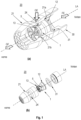
- Fig. 1 shows in Figure (a) a liquid jet device 20 according to the invention in a perspective view with a rectangular breakout of the housing 21 and in Figure (b) a liquid jet device 20 according to the invention in an exploded view.
- the housing 21 of the liquid jet device 20 is designed here to be essentially rotationally symmetrical. But it cannot be rotationally symmetrical either.
- the housing 21 has a recess on the inside, which is adapted to accommodate a swirling device 1 according to the invention by inserting the swirling device 1 into the recess of the housing 21 in the axial direction (along the longitudinal axis LA).
- the housing 21 On the open side (side on which the swirling device 1 is inserted into the housing 21), the housing 21 has an at least partially circumferential radial projection 21a, which serves as a stop for the swirling device 1.
- the swirling device 1 itself also has an at least partially circumferential radial projection 12 at its rear end, which corresponds to the radial projection 21a of the housing 21.
- the swirling device 1 is or can be pushed into the housing 21 until the radial projection 12 of the swirling device 1 rests on the radial projection 21a of the housing 21.
- the length of the swirling device 1 and the depth of the recess in the housing 21 are dimensioned such that when the swirling device 1 is completely accommodated in the housing 21 (when the radial projection 12 of the swirling device 1 rests on the radial projection 21a of the housing 21) between a cavity is formed at the front end of the swirling device 1 and the housing wall of the housing 21 opposite the front end of the swirling device 1.
- This cavity is referred to below as a calming chamber 22, the purpose of which is described in more detail below.
- the outer contour 13 of the swirling device 1 corresponds to the inner contour 21b of the housing 21.
- the calming chamber 22 is preferably separated from the rear part of the housing recess in a fluid and gas-tight manner.
- a circumferential sealing ring can be arranged at the front end of the swirling device 1.
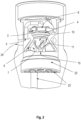
- the housing 21 At the front end of the housing 21 it has a number of flow straighteners 23. As shown in figure (a), these can be provided in the front housing wall of the housing 21 as axially extending boreholes which open into the calming chamber 22.
- the number of flow straighteners 23 depends on the specific area of application of the liquid jet device 20 according to the invention. In one embodiment, only a single flow straightener 23 can be provided. If there are several flow straighteners 23, these can each have the same diameter - alternatively, it can also be provided that the flow straighteners 23 have different diameters. In figure (a), the flow straighteners 23 have a circular cross section. However, other cross-sections are possible.
- an internal thread can be provided in the housing 21 in order to equip the liquid jet device 20 according to the invention with an extension piece 30 if necessary.
- a circumferential sealing ring 31 can be arranged between the extension piece 30 and the swirling device 1, which can preferably comprise a sieve.
- the swirling device 1 can be made of a metal, in particular stainless steel, a plastic, or a biological material, in particular biofibers and/or lignin.
- the housing 21 can be made of a metal, in particular stainless steel, a plastic, or a biological material, in particular biofibers and/or lignin.
- the housing 21 and the swirling device 1 can be provided or manufactured as two separate parts, wherein the swirling device 1 can be inserted into the housing 21, as described above.
- the housing 21 and the swirling device 1 can also be provided or manufactured as an integral part.
- Steps b) and c) mentioned above are optional.
- step c) is carried out in a modified form.
- the fluid supplied to the swirl chamber is swirled.
- the swirled fluid then passes from the vortex chamber via an expansion chamber 10, in which a number of guide vanes 6 are arranged, into the settling chamber 22.
- excess gas can separate from the fluid.
- a fluid On the fluid inlet side, a fluid is first supplied to an antechamber 2, the fluid preferably being pressurized.
- the fluid then passes from the antechamber 2 into a swirl chamber 4 via a number of swirl channels 3.
- the swirl channels 3 are designed to run largely tangentially to the swirl chamber. This ensures that pressurized fluid exits almost tangentially to the vortex chamber 4 when it flows into the vortex chamber 4 and thus creates a fast vortex or vortex. Due to the largely tangential course of the swirl channels 3, a sufficiently strong vortex can be generated in the swirl chamber 4 even at a very low pressure with which the fluid is supplied to the swirl chamber 4.
- the orientation of the swirl channels can be selected so that a clockwise vortex is generated in the vortex chamber 4.
- the speed of the vortex in the vortex chamber 4 can be influenced by the pressure with which the fluid is supplied to the vortex chamber 4. The higher the The pressure is chosen, the greater the speed of the vortex. As the speed of the vortex increases, the centrifugal force acting on the vortex also increases, which creates a counterpressure, which in turn limits the mass of fluid supplied as the pressure increases. This ensures optimal function of the swirl chamber 4 over a very wide pressure range, namely the generation of a swirled gas-fluid mixture.
- the rapidly rotating vortex in the vortex chamber 4 creates a negative pressure area in the vortex chamber 4, namely inside the vortex.
- This negative pressure causes a gas (for example ambient air) to be sucked into the swirl chamber via a number of suction openings 5, which are formed in the wall of the swirling device 1.
- the suction openings 5 or the suction channels can open into a fluid inlet-side through hole 8 of the swirl chamber 4. It is advantageous if the through hole 8 runs coaxially to the longitudinal axis LA of the swirling device 1. This creates a centrally focused gas jet (e.g. an air jet) which shoots at high speed centrally into the swirl chamber 4 and into the expansion chamber 10 downstream of the swirl chamber. This ensures uniform mixing of the supplied fluid with the sucked gas. Since as the pressure with which the fluid is supplied to the liquid jet device 20 increases, the flow rate also increases and at the same time the pressure in the swirl chamber also decreases, more gas is sucked in and is mixed with the fluid. This also ensures that as the flow rate increases, the proportion of gas in the gas-fluid mixture generated remains largely constant.
- a centrally focused gas jet e.g. an air jet
- the suction openings 5 correspond to radial suction openings 24 in the housing 21.
- the ambient air therefore reaches the suction openings 5 of the swirling device 1 via the radial suction openings 24 and from there via suction channels to the through hole 8 of the swirl chamber 4.
- a radially circumferential support structure 9 can be provided at the through hole 8, which here is essentially annular and projects into the vortex chamber 4 in the axial direction.
- the support structure 9 ensures that the vortex generated does not collapse, which could impair or even prevent mixing of the gas with the fluid.
- An expansion chamber 10 is provided downstream of the vortex chamber 4, which essentially has a conical shape, in particular a frustoconical shape (internal volume), with the region 11 of the expansion chamber 10 with the smallest diameter facing the vortex chamber 4. This means that the diameter of the expansion chamber 10 increases downstream, which ensures that the gas-fluid mixture that passes from the swirl chamber 4 into the expansion chamber 10 expands.
- a plurality of guide vanes 6 are arranged in the expansion chamber 10, each of which can have a curved guide surface 7.
- the guide vanes 6 are arranged in the expansion chamber 10 in such a way that they receive the gas-fluid mixture from the vortex chamber 4 and lead it via the respective guide surfaces 7 into the settling chamber 22 downstream of the expansion chamber 10, whereby the flow direction and the angular momentum of the gas-fluid -Mixture can be influenced.
- the gas-fluid mixture supplied to the settling chamber 22 now has a significantly reduced vortex speed, which allows the fluid saturated with the gas to be separated from excess gas.
- a number of flow straighteners 23 are connected downstream of the calming chamber 22, through which the gas-fluid mixture is led out of the liquid jet device 20.
- the flow straighteners 23 can be designed as axially extending boreholes. From the liquid jet device 20 then rectified gas-fluid jets (e.g. water enriched with air) emerge.
- the emerging jet is compactly shaped and is suitable, for example, for filling glasses or bottles.
- the liquid jet device 20 can be used, for example, as a jet regulator for household water fittings.
Abstract
Bereitgestellt wird eine Verwirbelungsvorrichtung zum Bereitstellen eines verwirbelten Fluids, wobei die Verwirbelungsvorrichtung zumindest eine Vorkammer, die mittels zumindest eines Drallkanals in Fluidkommunikation mit einer Wirbelkammer steht, sodass ein Fluid beim Einströmen von der Vorkammer in die Wirbelkammer tangential zur Wirbelkammer in eine Kreisströmung beschleunigbar ist, und mehrere Leitschaufeln, mittels der das verwirbelte Fluid stromabwärts bereitstellbar ist, umfasst. Bereitgestellt wird ferner eine Flüssigkeitsstrahlvorrichtung mit einer erfindungsgemäßen Verwirbelungsvorrichtung.A swirling device is provided for providing a swirled fluid, wherein the swirling device has at least one prechamber, which is in fluid communication with a swirl chamber by means of at least one swirl channel, so that a fluid can be accelerated into a circular flow when flowing from the prechamber into the swirl chamber tangentially to the swirl chamber, and comprises a plurality of guide vanes, by means of which the swirled fluid can be provided downstream. A liquid jet device with a swirling device according to the invention is also provided.
Description
Die Erfindung betrifft eine Vorrichtung zur Verwirbelung einer Flüssigkeit, wobei die Vorrichtung beispielsweise als Strahlregler für Wasserarmaturen, etwa ein Wasserhahn, verwendet werden kann.The invention relates to a device for swirling a liquid, wherein the device can be used, for example, as a jet regulator for water fittings, such as a tap.
Vorrichtungen zur Verwirbelung einer Flüssigkeit, etwa Wasser, sind aus dem Stand der Technik bekannt.Devices for swirling a liquid, such as water, are known from the prior art.
So ist etwa aus der
Aufgabe der vorliegenden Erfindung ist es daher, eine verbesserte Vorrichtung zur Verwirbelung einer Flüssigkeit bereitzustellen.The object of the present invention is therefore to provide an improved device for swirling a liquid.
Gelöst wird diese Aufgabe mit einer Verwirbelungsvorrichtung und einer Flüssigkeitsstrahlvorrichtung mit einer erfindungsgemäßen Verwirbelungsvorrichtung gemäß den unabhängigen Ansprüchen. Vorteilhafte Ausgestaltungen der Erfindung sind in den jeweiligen abhängigen Ansprüchen angegeben.This problem is solved with a swirling device and a liquid jet device with a swirling device according to the invention according to the independent claims. Advantageous embodiments of the invention are specified in the respective dependent claims.
Bereit gestellt wird demnach eine Verwirbelungsvorrichtung zum Bereitstellen eines verwirbelten Fluids, wobei die Verwirbelungsvorrichtung umfasst:
- zumindest eine Vorkammer, die mittels zumindest eines Drallkanals in Fluidkommunikation mit einer Wirbelkammer steht, sodass ein Fluid beim Einströmen von der Vorkammer in die Wirbelkammer tangential zur Wirbelkammer in eine Kreisströmung beschleunigbar ist, und
- mehrere Leitschaufeln, mittels der das verwirbelte Gas-Fluid-Gemisch stromabwärts bereitstellbar ist.
- at least one antechamber, which is in fluid communication with a vortex chamber by means of at least one swirl channel, so that a fluid can be accelerated into a circular flow tangentially to the vortex chamber when flowing from the antechamber into the vortex chamber, and
- several guide vanes, by means of which the swirled gas-fluid mixture can be made available downstream.
Hierbei wird der Vorkammer das Fluid zugeführt.The fluid is supplied to the antechamber.
In einer Ausgestaltung der Erfindung kann die Verwirbelungsvorrichtung zumindest eine mit der Umgebung in Fluidkommunikation stehenden Ansaugöffnung umfassen, die derart in Fluidkommunikation mit der Wirbelkammer steht, dass bei einem Unterdruck in der Wirbelkammer ein Umgebungsgas durch die zumindest eine Ansaugöffnung in die Wirbelkammer einbringbar ist und mit dem Fluid zu dem verwirbelten Gas-Fluid-Gemisch vermischbar ist, wobei der Unterdruck durch die Kreisströmung des Fluids in der Wirbelkammer erzeugt wirdIn one embodiment of the invention, the swirling device can comprise at least one suction opening which is in fluid communication with the environment and which is in fluid communication with the swirl chamber in such a way that, when there is a negative pressure in the swirl chamber, an ambient gas can be introduced into the swirl chamber through the at least one suction opening and with the Fluid can be mixed to form the swirled gas-fluid mixture, the negative pressure being generated by the circular flow of the fluid in the swirl chamber
Das Fluid ist hierbei eine Flüssigkeit, insbesondere Wasser, wobei die Erfindung nicht auf Wasser beschränkt ist. Es kann jede Flüssigkeit verwendet werden, die geeignet ist, mit einem Gas verwirbelt zu werden, um ein Gas-Fluid-Gemisch bereitzustellen, beispielsweise Öle oder biologische Flüssigkeiten. Das Fluid kann hierbei auch ein Fluidgemisch sein.The fluid here is a liquid, in particular water, although the invention is not limited to water. Any liquid capable of being swirled with a gas to provide a gas-fluid mixture can be used, for example oils or biological liquids. The fluid can also be a fluid mixture.
Als Gas kann jedes beliebige Gas verwendet werden, das geeignet ist, mit dem Fluid verwirbelt zu werden, um ein Gas-Fluid-Gemisch bereitzustellen. In einer Ausgestaltung der Erfindung kann Luft als Gas verwendet, insbesondere dann, wenn als Fluid Wasser verwendet wird. In einer weiteren Ausgestaltung kann das Gas auch ein Plasma sein. Das Gas kann auch ein Gasgemisch umfassen.The gas used can be any gas that is suitable for being swirled with the fluid to provide a gas-fluid mixture. In one embodiment of the invention, air can be used as a gas, especially if water is used as the fluid. In a further embodiment, the gas can also be a plasma. The gas can also include a gas mixture.
"Tangential zur Wirbelkammer in eine Kreisströmung beschleunigbar" bedeutet hierbei, dass das über den Drallkanal der Wirbelkammer zugeführte Fluid in der Wirbelkammer um die Achse der Wirbelkammer rotiert und so einen Vortex bzw. Wirbel erzeugt.“Can be accelerated tangentially to the vortex chamber into a circular flow” means that the fluid supplied via the swirl channel of the vortex chamber rotates in the vortex chamber about the axis of the vortex chamber and thus creates a vortex or vortex.
Durch den Vortex bzw. Wirbel entsteht in der Wirbelkammer ein Unterdruck, der dazu führt, dass über die Ansaugöffnung ein Gas in die Wirbelkammer eingesaugt wird und das Fluid mit dem eingesaugten Gas gemischt wird.The vortex or vortex creates a negative pressure in the vortex chamber, which leads to a gas being sucked into the vortex chamber via the suction opening and the fluid being mixed with the sucked-in gas.
Bei einer Druckerhöhung des der Vorkammer zugeführten Fluids erhöht sich auch die Geschwindigkeit des in der Wirbelkammer erzeugten Wirbels, wodurch wiederum der Druck im Inneren des Wirbels abnimmt. Bei einer Druckerhöhung des der Vorkammer zugeführten Fluids wird damit auch mehr Gas über die Ansaugöffnung angesaugt und mit dem Fluid gemischt, sodass eine gleichmäßige Durchmischung des Fluids mit dem Gas gewährleistet ist.When the pressure of the fluid supplied to the antechamber increases, the speed of the vortex generated in the vortex chamber also increases, which in turn reduces the pressure inside the vortex. When the pressure of the fluid supplied to the antechamber increases, more gas is sucked in via the suction opening and mixed with the fluid, so that uniform mixing of the fluid with the gas is ensured.
In einer Ausgestaltung der Erfindung können die mehreren Leitschaufeln jeweils eine gekrümmte Leitfläche aufweisen, wobei die Leitflächen die Strömungsrichtung des stromabwärts bereitgestellten Fluids bzw. Gas-Fluid-Gemisches beeinflussen können.In one embodiment of the invention, the plurality of guide vanes can each have a curved guide surface, wherein the guide surfaces can influence the flow direction of the fluid or gas-fluid mixture provided downstream.
Die Leitschaufeln nehmen das Gas-Fluid-Gemisch aus der Wirbelkammer auf, um es stromabwärts bereitzustellen.The vanes receive the gas-fluid mixture from the swirl chamber to provide it downstream.
Vorteilhaft kann es ein, wenn die Leitschaufeln in einer Expansionskammer angeordnet sind, wobei die Expansionskammer eine konische Form aufweist und über eine offene Engstelle mit der Wirbelkammer verbunden ist. Das bedeutet, dass die Expansionskammer wirbelkammerseitig den kleinsten Durchmesser aufweist. Durch den sich stromabwärts vergrößernden Durchmesser der Expansionskammer wird der Drehimpuls des von den Leitschaufeln aus der Wirbelkammer aufgenommene Gas-Fluid-Gemisch reduziert.It can be advantageous if the guide vanes are arranged in an expansion chamber, the expansion chamber having a conical shape and being connected to the vortex chamber via an open constriction. This means that the expansion chamber has the smallest diameter on the swirl chamber side. As the diameter of the expansion chamber increases downstream, the angular momentum of the gas-fluid mixture absorbed from the vortex chamber by the guide vanes is reduced.
Die Expansionskammer und die Wirbelkammer bilden zusammen ein im Wesentlichen sanduhrförmiges Innenvolumen.The expansion chamber and the vortex chamber together form a substantially hourglass-shaped internal volume.
Vorteilhaft kann es sein, wenn die zumindest eine Ansaugöffnung durch ein zentrales, axiales erstes Durchgangsloch der Wirbelkammer mit der Wirbelkammer verbunden ist. Vorteilhaft kann es hierbei sein, wenn das axiale erste Durchgangsloch der Wirbelkammer als koaxiales erstes Durchgangsloch (bezogen auf die Achse der Wirbelkammer) ausgebildet ist. Dadurch wird gewährleistet, dass das über die Ansaugöffnung bzw. Ansaugöffnungen angesaugte Gas zentral gebündelt wird und als Gasstrahl mit hoher Geschwindigkeit zentral in die Wirbelkammer und in die Expansionskammer eingebracht wird.It can be advantageous if the at least one suction opening is connected to the vortex chamber through a central, axial first through hole of the vortex chamber. It can be advantageous here if the axial first through hole of the vortex chamber is designed as a coaxial first through hole (relative to the axis of the vortex chamber). This ensures that the gas sucked in via the suction opening or suction openings is centrally bundled and introduced as a gas jet at high speed centrally into the swirl chamber and into the expansion chamber.
In einer Ausgestaltung der Erfindung kann das erste Durchgangsloch an seiner Umrandung wirbelkammerseitig eine im Wesentlichen kreisförmige Stützstruktur zur Stabilisierung der Kreisströmung, d.h. des Wirbels, aufweisen. Die Stützstruktur kann hierbei in die Wirbelkammer hineinragen. Das bedeutet, dass die Stützstruktur als wirbelkammerseitig um das erste Durchgangsloch radial herumlaufende Struktur ausgebildet ist. Dadurch wird verhindert, dass der Wirbel bzw. Vortex unkontrolliert zusammenbricht und dadurch die Gaszufuhr über das erste Durchgangsloch beeinträchtigt oder gar verhindert.In one embodiment of the invention, the first through hole can have a substantially circular support structure on its edge on the swirl chamber side for stabilizing the circular flow, i.e. the vortex. The support structure can protrude into the vortex chamber. This means that the support structure is designed as a structure that runs radially around the first through hole on the swirl chamber side. This prevents the vortex or vortex from collapsing in an uncontrolled manner and thereby impairing or even preventing the gas supply via the first through hole.
In einer Ausgestaltung der Erfindung kann im Bereich der Leitschaufeln, d.h. in der Expansionskammer, ein zweites Durchgangsloch angeordnet sein.In one embodiment of the invention, a second through hole can be arranged in the area of the guide vanes, ie in the expansion chamber.
Vorteilhaft ist es hierbei, wenn das zweite Durchgangsloch koaxial zum ersten Durchgangsloch verläuft.It is advantageous here if the second through hole runs coaxially to the first through hole.
Über das zweite Durchgangsloch kann das über das erste Durchgangsloch angesaugte Gas einer der Expansionskammer nachgeschalteten Beruhigungskammer zugeführt werden.The gas sucked in via the first through hole can be fed to a settling chamber downstream of the expansion chamber via the second through hole.
In einer vorteilhaften Ausgestaltung der Erfindung kann die Verwirbelungsvorrichtung einstückig ausgebildet sein. "Einstückig" bedeutet hierbei, dass die Verwirbelungsvorrichtung von einem integralen Teil gebildet wird. Im Sinne der vorliegenden Erfindung bedeutet "einstückig" auch, dass die Verwirbelungsvorrichtung aus mehreren Teilen besteht, die nicht zerstörungsfrei auseinandernehmbar sind.In an advantageous embodiment of the invention, the swirling device can be designed in one piece. “In one piece” here means that the swirling device is formed by an integral part. In the context of the present invention, “one-piece” also means that the swirling device consists of several parts that cannot be taken apart without being destroyed.
Die Verwirbelungsvorrichtung kann zumindest teilweise aus
- einem Metall, insbesondere Edelstahl,
- einem Kunststoff, oder
- einem biologischen Material, insbesondere Biofasern und/oder Lignin gefertigt sein.
- a metal, especially stainless steel,
- a plastic, or
- a biological material, in particular biofibers and/or lignin.
Bereit gestellt wird durch die Erfindung ferner eine Flüssigkeitsstrahlvorrichtung, umfassend
- eine erfindungsgemäße Verwirbelungsvorrichtung, und
- ein Gehäuse zur Aufnahme der Verwirbelungsvorrichtung.
- a swirling device according to the invention, and
- a housing to accommodate the swirling device.
In dem Gehäuse ist stromabwärts anschließend an die Expansionskammer eine Beruhigungskammer ausgebildet zur Aufnahme des von der Verwirbelungsvorrichtung bereitgestellten verwirbelten Fluids bzw. Gas-Fluid-Gemisches. Die Verwirbelungsvorrichtung und das Gehäuse sind so ausgestaltet, dass bei einer vollständigen Aufnahme der Verwirbelungsvorrichtung in dem Gehäuse stromabwärts eine Beruhigungskammer ausgebildet ist.A settling chamber is formed in the housing downstream of the expansion chamber to accommodate the swirled fluid or gas-fluid mixture provided by the swirling device. The swirling device and the housing are designed in such a way that when the swirling device is completely accommodated in the housing, a settling chamber is formed downstream.
Aus dem von der Verwirbelungsvorrichtung der Beruhigungskammer zugeführten Fluid bzw. Gas-Fluid-Gemisch wird überschüssiges Gas von dem Fluid bzw. Gas-Fluid-Gemisch getrennt.Excess gas is separated from the fluid or gas-fluid mixture from the fluid or gas-fluid mixture supplied to the settling chamber by the swirling device.
In einer Ausgestaltung der Erfindung kann die Flüssigkeitsstrahlvorrichtung zumindest einen, vorzugsweise mehrere Strömungsgleichrichter aufweisen, mittels denen das verwirbelte Gas-Fluid-Gemisch als ein Flüssigkeitsstrahl, vorzugsweise als mehrere Flüssigkeitsstrahlen bereitstellbar ist.In one embodiment of the invention, the liquid jet device can have at least one, preferably several, flow straighteners, by means of which the swirled gas-fluid mixture can be provided as a liquid jet, preferably as several liquid jets.
In einer Ausgestaltung der Flüssigkeitsstrahlvorrichtung können die Strömungsgleichrichter jeweils als axiales Bohrloch ausgebildet sein.In one embodiment of the liquid jet device, the flow straighteners can each be designed as an axial borehole.
Vorteilhaft kann es ein, wenn die Flüssigkeitsstrahlvorrichtung ferner zumindest eine Ansaugöffnung umfasst, die zu der zumindest einen Ansaugöffnung der Verwirbelungsvorrichtung korrespondiert. Vorzugsweise handelt es sich bei der zumindest einen Ansaugöffnung der Flüssigkeitsstrahlvorrichtung um eine radiale Ansaugöffnung, die vorzugsweise in einer Seitenwandung der Flüssigkeitsstrahlvorrichtung ausgebildet ist.It can be advantageous if the liquid jet device further comprises at least one suction opening which corresponds to the at least one suction opening of the swirling device. Preferably, the at least one suction opening of the liquid jet device is a radial suction opening, which is preferably formed in a side wall of the liquid jet device.
In einer Ausgestaltung der Erfindung kann die Flüssigkeitsstrahlvorrichtung eine Gewindeschnittstelle aufweisen, die mittels einer Dichtung mit der Verwirbelungsvorrichtung stromeingangs gekoppelt ist.In one embodiment of the invention, the liquid jet device can have a threaded interface which is coupled to the swirling device at the current input by means of a seal.
Die Dichtung kann hierbei ein Sieb umfassen.The seal can include a sieve.
Weitere Einzelheiten und Merkmale der Erfindung ergeben sich aus der nachfolgenden Beschreibung in Verbindung mit der Zeichnung. Es zeigt:
- Fig. 1
- eine erfindungsgemäße Flüssigkeitsstrahlvorrichtung in einer perspektivischen Ansicht mit einem rechtwinkeligen Ausbruch des Gehäuses (Abbildung a) und in einer Explosionsdarstellung (Abbildung b);
- Fig. 2
- eine erfindungsgemäße Flüssigkeitsstrahlvorrichtung mit einer darin angeordneten Verwirbelungsvorrichtung in einem Teilschnitt;
- Fig. 3
- einer erfindungsgemäße Verwirbelungsvorrichtung in einer Seitenansicht (Abbildung a) und in einer Schnittansicht entlang der Schnittachse A-A (Abbildung b);
- Fig. 4
- eine erfindungsgemäße Verwirbelungsvorrichtung in einer perspektivischen Darstellung; und
- Fig. 5
- eine erfindungsgemäße Verwirbelungsvorrichtung in einer perspektivischen Darstellung mit einem rechtwinkeligen Ausbruch.
- Fig. 1
- a liquid jet device according to the invention in a perspective view with a rectangular breakout of the housing (figure a) and in an exploded view (figure b);
- Fig. 2
- a partial section of a liquid jet device according to the invention with a swirling device arranged therein;
- Fig. 3
- a swirling device according to the invention in a side view (Figure a) and in a sectional view along the section axis AA (Figure b);
- Fig. 4
- a swirling device according to the invention in a perspective view; and
- Fig. 5
- a swirling device according to the invention in a perspective view with a rectangular breakout.
In den nachfolgend beschriebenen Figuren sind jeweils Ausführungsformen der Erfindung beschrieben, bei denen die Verwirbelungsvorrichtung zumindest eine Ansaugöffnung aufweist, durch die ein Gas in die Wirbelkammer einbringbar ist, um mit dem Fluid vermischt zu werden.The figures described below each describe embodiments of the invention in which the swirling device has at least one suction opening through which a gas can be introduced into the swirl chamber in order to be mixed with the fluid.
Erfindungsgemäß kann auf solche Ansaugöffnungen auch verzichtet werden, sodass die Verwirbelungsvorrichtung im Wesentlichen ausgestaltet ist, ein in die Wirbelkammer eingebrachtes Fluid zu verwirbeln.According to the invention, such suction openings can also be dispensed with, so that the swirling device is essentially designed to swirl a fluid introduced into the swirl chamber.
Das Gehäuse 21 der Flüssigkeitsstrahlvorrichtung 20 ist hier im Wesentlichen rotationssymmetrisch ausgestaltet. Es kann aber auch nicht rotationssymmetrisch sein. Das Gehäuses 21 weist im Inneren eine Aussparung auf, die angepasst ist, eine erfindungsgemäße Verwirbelungsvorrichtung 1 aufzunehmen, indem die Verwirbelungsvorrichtung 1 in axialer Richtung (entlang der Längsachse LA) in die Aussparung des Gehäuses 21 eingeschoben wird. Das Gehäuse 21 weist an der offenen Seite (Seite, an der die Verwirbelungsvorrichtung 1 in das Gehäuse 21 eingeschoben wird) einen zumindest teilweise umlaufenden radialen Vorsprung 21a auf, der als Anschlag für die Verwirbelungsvorrichtung 1 dient. Die Verwirbelungsvorrichtung 1 selbst weist an ihrem hinteren Ende ebenfalls einen zumindest teilweise umlaufenden radialen Vorsprung 12 auf, der mit dem radialen Vorsprung 21a des Gehäuses 21 korrespondiert. Die Verwirbelungsvorrichtung 1 wird bzw. kann so weit in das Gehäuse 21 eingeschoben werden, bis der radiale Vorsprung 12 der Verwirbelungsvorrichtung 1 an dem radialen Vorsprung 21a des Gehäuses 21 aufliegt.The
Die Länge der Verwirbelungsvorrichtung 1 und die Tiefe der Aussparung in dem Gehäuse 21 sind so dimensioniert, dass bei einer vollständigen Aufnahme der Verwirbelungsvorrichtung 1 in das Gehäuse 21 (wenn der radiale Vorsprung 12 der Verwirbelungsvorrichtung 1 an dem radialen Vorsprung 21a des Gehäuses 21 aufliegt) zwischen dem vorderen Ende der Verwirbelungsvorrichtung 1 und der dem vorderen Ende der Verwirbelungsvorrichtung 1 gegenüberliegenden Gehäusewandung des Gehäuses 21 ein Hohlraum ausgebildet wird. Dieser Hohlraum wird nachfolgend als Beruhigungskammer 22 bezeichnet, deren Zweck nachfolgend näher beschrieben wird.The length of the swirling
Im Bereich des vorderen Endes der Verwirbelungsvorrichtung 1 korrespondiert die Außenkontur 13 der Verwirbelungsvorrichtung 1 mit der Innenkontur 21b des Gehäuses 21. Vorzugsweise wird in diesem Bereich die Beruhigungskammer 22 fluid-und gasdicht von dem hinteren Teil der Gehäuseaussparung getrennt. In einer Ausgestaltung der Erfindung kann am vorderen Ende der Verwirbelungsvorrichtung 1 ein umlaufender Dichtungsring angeordnet werden.In the area of the front end of the swirling
Am vorderen Ende des Gehäuses 21 weist diese eine Anzahl von Strömungsgleichrichter 23 auf. Diese können, wie in Abbildung (a) gezeigt, in der vorderen Gehäusewandung des Gehäuses 21 als axial verlaufende Bohrlöcher vorgesehen sein, die in die Beruhigungskammer 22 münden. Die Anzahl der Strömungsgleichrichter 23 hängt vom konkreten Einsatzgebiet der erfindungsgemäßen Flüssigkeitsstrahlvorrichtung 20 ab. So kann in einer Ausgestaltung auch nur ein einziger Strömungsgleichrichter 23 vorgesehen werden. Bei mehreren Strömungsgleichrichtern 23 können diese den jeweils gleichen Durchmesser aufweisen - alternativ kann es auch vorsehen sein, dass die Strömungsgleichrichter 23 unterschiedliche Durchmesser aufweisen. In Abbildung (a) weisen die Strömungsgleichrichter 23 einen kreisrunden Querschnitt auf. Andere Querschnitte sind aber möglich.At the front end of the
Am hinteren Ende der erfindungsgemäßen Flüssigkeitsstrahlvorrichtung 20 kann in dem Gehäuse 21 ein Innengewinde vorgesehen sein, um bei Bedarf die erfindungsgemäß Flüssigkeitsstrahlvorrichtung 20 mit einem Verlängerungsstück 30 zu bestücken. Zwischen dem Verlängerungsstück 30 und der Verwirbelungsvorrichtung 1 kann ein umlaufender Dichtungsring 31 angeordnet werden, der vorzugsweise ein Sieb umfassen kann. Mittels des Verlängerungsstückes 30 kann die erfindungsgemäße Flüssigkeitsstrahlvorrichtung 20 beispielsweise an einen Haushaltswasserhahn angeschlossen werden.At the rear end of the
Die Verwirbelungsvorrichtung 1 kann aus einem Metall, insbesondere Edelstahl, einem Kunststoff, oder einem biologischen Material, insbesondere Biofasern und/oder Lignin gefertigt sein.The swirling
Das Gehäuse 21 kann aus einem Metall, insbesondere Edelstahl, einem Kunststoff, oder einem biologischen Material, insbesondere Biofasern und/oder Lignin gefertigt sein.The
Das Gehäuse 21 und die Verwirbelungsvorrichtung 1 können als zwei separate Teile bereitgestellt bzw. hergestellt werden, wobei die Verwirbelungsvorrichtung 1 in das Gehäuse 21 eingeschoben werden kann, wie vorstehend beschrieben. Alternativ hierzu können das Gehäuse 21 und die Verwirbelungsvorrichtung 1 auch als integrales Teil bereitgestellt bzw. hergestellt werden.The
In Abbildung (a) der
- a) Ein Fluid, beispielsweise Wasser, wird von hinten der Verwirbelungsvorrichtung 1 mit Druck zugeführt. Das Fluid gelangt dann in eine Wirbelkammer und bildet dort einen Wirbel bzw. Vortex.
- b) Gleichzeitig wird über eine radiale Ansaugöffnung 24
im Gehäuse 21 und über eine Ansaugöffnung 5der Verwirbelungsvorrichtung 1 ein Gas (z.B. Umgebungsluft) der in eine Wirbelkammer zugeführt. In einer Ausgestaltung der Erfindung wird das Gas aufgrund eines Unterdruckes in der Wirbelkammer angesaugt. - c) In der Wirbelkammer vermischen sich das zugeführte Fluid und das zugeführte bzw. angesaugte Gas und bilden so ein Gas-Fluid-Gemisch. Das Gas-Fluid-Gemisch gelangt dann von der Wirbelkammer über eine Expansionskammer 10, in der eine
Anzahl von Leitschaufeln 6 angeordnet sind, indie Beruhigungskammer 22. Inder Beruhigungskammer 22 kann sich überschüssiges Gas von dem Fluid trennen. - d) Aus der Beruhigungskammer 22 tritt das Gas-Fluid-Gemisch über eine
Anzahl von Strömungsgleichrichtern 23 aus der Flüssigkeitsstrahlvorrichtung 20 aus.
- a) A fluid, for example water, is supplied under pressure to the swirling
device 1 from behind. The fluid then enters a vortex chamber and forms a vortex or vortex. - b) At the same time, a gas (eg ambient air) is fed into a swirl chamber via a radial suction opening 24 in the
housing 21 and via asuction opening 5 of the swirlingdevice 1. In one embodiment of the invention, the gas is sucked in due to a negative pressure in the swirl chamber. - c) In the swirl chamber, the supplied fluid and the supplied or sucked gas mix and thus form a gas-fluid mixture. The gas-fluid mixture then passes from the vortex chamber via an
expansion chamber 10, in which a number ofguide vanes 6 are arranged, into the settlingchamber 22. In the settlingchamber 22, excess gas can separate from the fluid. - d) The gas-fluid mixture emerges from the calming
chamber 22 from theliquid jet device 20 via a number offlow straighteners 23.
Die vorstehend genannten Schritte b) und c) sind optional. Für dne Fall, dass der Schritt b) nicht ausgeführt wird, wird der Schritt c) in abgewandelter Form durchgeführt. Gemäß des abgewandelten Schrittes c) wird das der Wirbelkammer zugeführte Fluid verwirbelt. Das verwirbelte Fluid gelangt dann von der Wirbelkammer über eine Expansionskammer 10, in der eine Anzahl von Leitschaufeln 6 angeordnet sind, in die Beruhigungskammer 22. In der Beruhigungskammer 22 kann sich überschüssiges Gas von dem Fluid trennen.Steps b) and c) mentioned above are optional. In the event that step b) is not carried out, step c) is carried out in a modified form. According to the modified step c), the fluid supplied to the swirl chamber is swirled. The swirled fluid then passes from the vortex chamber via an
Nachfolgend werden
Fluideingangsseitig wird ein Fluid zunächst einer Vorkammer 2 zugeführt, wobei das Fluid vorzugsweise mit einem Druck beaufschlagt ist.On the fluid inlet side, a fluid is first supplied to an
Über eine Anzahl von Drallkanälen 3 gelangt das Fluid dann von der Vorkammer 2 in eine Wirbelkammer 4. Die Drallkanäle 3 sind weitgehend tangential zur Wirbelkammer verlaufend ausgebildet. Dadurch wird erreicht, dass mit einem Druck beaufschlagtes Fluid beim Einströmen in die Wirbelkammer 4 nahezu tangential zur Wirbelkammer 4 austritt und so einen schnellen Wirbel bzw. Vortex erzeugt. Durch den weitgehend tangentialen Verlauf der Drallkanäle 3 kann selbst bei einem sehr geringen Druck, mit dem das Fluid der Wirbelkammer 4 zugeführt wird, en ausreichend starker Wirbel in der Wirbelkammer 4 erzeugt werden. Die Ausrichtung der Drallkanäle kann so gewählt werden, dass in der Wirbelkammer 4 ein rechtsdrehender Wirbel erzeugt wird. Beim Einströmen des Fluid von der Vorkammer in die Wirbelkammer tangential zur Wirbelkammer ist das Fluid also in eine Kreisströmung beschleunigbar.The fluid then passes from the
Die Geschwindigkeit des Wirbels in der Wirbelkammer 4 lässt sich mittels des Druckes, mit der das Fluid der Wirbelkammer 4 zugeführt beeinflussen. Je höher der Druck gewählt wird, umso größer ist die Geschwindigkeit des Wirbels. Mit der Geschwindigkeit des Wirbels steigt auch die auf den Wirbel wirkende Fliehkraft, die einen Gegendruck erzeugt, der wiederum die zugeführte Masse an Fluid bei zunehmendem Druck begrenzt. Damit wird über einen sehr breiten Druckbereich eine optimale Funktion der Wirbelkammer 4 gewährleistet, nämlich das Erzeugen eines verwirbelten Gas-Fluid-Gemisches.The speed of the vortex in the
Der sich in der Wirbelkammer 4 schnelldrehende Wirbel erzeugt in der Wirbelkammer 4 einen Unterdruckbereich, nämlich im Inneren des Wirbels. Dieser Unterdruck bewirkt, dass über eine Anzahl von Ansaugöffnungen 5, die in der Wandung der Verwirbelungsvorrichtung 1 ausgebildet sind, ein Gas (beispielsweise Umgebungsluft) in die Wirbelkammer angesaugt wird.The rapidly rotating vortex in the
Die Ansaugöffnungen 5 bzw. die Ansaugkanäle können in einem fluideintrittsseitigen Durchgangsloch 8 der Wirbelkammer 4 münden. Vorteilhaft ist es, wenn das Durchgangsloch 8 koaxial zur Längsachse LA der Verwirbelungsvorrichtung 1 verläuft. Dadurch wird ein zentral gebündelter Gasstrahl (z.B. ein Luftstrahl) erzeugt, der mit hoher Geschwindigkeit zentral in die Wirbelkammer 4 und in die der Wirbelkammer nachgeschalteten Expansionskammer 10 einschießt. Dadurch wird ein gleichmäßiges Durchmischen des zugeführten Fluids mit dem angesaugten Gas gewährleistet. Da bei zunehmendem Druck, mit dem das Fluid der Flüssigkeitsstrahlvorrichtung 20 zugeführt wird, auch die Durchflussmenge erhöht wird und gleichzeitig auch der Druck in der Wirbelkammer abnimmt, wird auch mehr Gas angesaugt, das mit dem Fluid vermischt wird. Dadurch wird also auch gewährleistet, dass bei zunehmender Durchflussmenge der Anteil an Gas im erzeugten Gas-Fluid-gemisch weitgehend konstant bleibt.The
Die Ansaugöffnungen 5 korrespondieren mit radialen Ansaugöffnung 24 im Gehäuse 21. Die Umgebungslust gelangt also über die radialen Ansaugöffnungen 24 zu den Ansaugöffnungen 5 der Verwirbelungsvorrichtung 1 und von dort über Ansaugkanäle zum Durchgangsloch 8 der Wirbelkammer 4.The
Am Durchgangsloch 8 kann eine radial umlaufende Stützstruktur 9 vorgesehen sein, die hier im Wesentlichen ringförmig ausgestaltet ist und in axialer Richtung in die Wirbelkammer 4 hineinragt. Die Stützstruktur 9 gewährleistet, dass der erzeugte Wirbel nicht zusammenbricht, was ein Durchmischen des Gases mit dem Fluid beeinträchtigen oder gar verhindern könnte.A radially
Nachgeschaltet an die Wirbelkammer 4 ist eine Expansionskammer 10 vorgesehen, die im Wesentlichen eine konische Form, insbesondere kegelstumpfförmige Form (Innenvolumen) aufweist, wobei der Bereich 11 der Expansionskammer 10 mit dem kleinsten Durchmesser der Wirbelkammer 4 zugewandt ist. Das bedeutet, dass sich der Durchmesser der Expansionskammer 10 stromabwärts vergrößert, was ein Entspannen des Gas-Fluid-Gemisches, das von der Wirbelkammer 4 in die Expansionskammer 10 gelangt, gewährleistet.An
In der Expansionskammer 10 sind mehrere Leitschaufeln 6 angeordnet, die jeweils eine gekrümmte Leitfläche 7 aufweisen können. Die Leitschaufeln 6 sind so in der Expansionskammer 10 angeordnet, dass sie das Gas-Fluid-Gemisch aus der Wirbelkammer 4 aufnehmen und über die jeweiligen Leitflächen 7 in die der Expansionskammer 10 nachgeschalteten Beruhigungskammer 22 führen, wodurch die Strömungsrichtung und der Drehimpuls des Gas-Fluid-Gemisches beeinflusst werden.A plurality of
Das der Beruhigungskammer 22 zugeführte Gas-Fluid-Gemisch weist nun eine deutliche reduzierte Vortexgeschwindigkeit auf, die es ermöglicht, dass das mit dem Gas gesättigte Fluid von überschüssigem Gas getrennt wird.The gas-fluid mixture supplied to the settling
An die Beruhigungskammer 22 schließen sich stromabwärts eine Anzahl von Strömungsgleichrichter 23 an, durch die das Gas-Fluid-Gemisch aus der Flüssigkeitsstrahlvorrichtung 20 herausgeführt wird. Die Strömungsgleichrichter 23 können als axial verlaufende Bohrlöcher ausgestaltet sein. Aus der Flüssigkeitsstrahlvorrichtung 20 treten dann gleichgerichtete Gas-Fluid-Strahlen (z.B. ein mit Luft angereichertes Wasser) aus. Der austretende Strahl ist kompakt geformt und eignet sich beispielsweise zum Befüllen von Gläsern oder Flaschen.A number of
In einer Ausgestaltung der Erfindung und lediglich bespielhaft, kann die Flüssigkeitsstrahlvorrichtung 20 etwa als Strahlregler für Haushaltswasserarmaturen verwendet werden.In one embodiment of the invention and purely by way of example, the
- 11
- VerwirbelungsvorrichtungSwirling device
- 22
-
Vorkammer der Verwirbelungsvorrichtung 1Antechamber of the swirling
device 1 - 33
- Drallkanal bzw. DrallkanäleSwirl channel or swirl channels
- 44
- Wirbelkammer (Vortexkammer)Vortex chamber
- 55
-
Ansaugöffnung der Verwirbelungsvorrichtung 1Suction opening of the swirling
device 1 - 66
- Leitschaufel bzw. LeitschaufelnGuide vane or vanes
- 77
- Leitfläche(n) der Leitschaufel(n) 6Guide surface(s) of the guide vane(s) 6
- 88th
-
(erstes) Durchgangsloch der Wirbelkammer 4(first) through hole of the
vortex chamber 4 - 99
-
Stützstruktur des Durchgangsloches 8Support structure of the through
hole 8 - 1010
-
Expansionskammer der Verwirbelungsvorrichtung 1Expansion chamber of the swirling
device 1 - 1111
-
Engstelle der Expansionskammer 10Constriction of the
expansion chamber 10 - 1212
-
umlaufender radialer Vorsprung an der Verwirbelungsvorrichtung 1circumferential radial projection on the swirling
device 1 - 1313
-
Außenkontur des vorderen Endes der Verwirbelungsvorrichtung 1Outer contour of the front end of the swirling
device 1 - 1515
-
(zweites) Durchgangsloch im Bereich der Leitschaufeln 6(second) through hole in the area of the
guide vanes 6 - 2020
- FlüssigkeitsstrahlvorrichtungLiquid jet device
- 2121
-
Gehäuse der Flüssigkeitsstrahlvorrichtung 20Housing of the
liquid jet device 20 - 21a21a
-
umlaufender radialer Vorsprung im Gehäuse 21circumferential radial projection in the
housing 21 - 21b21b
-
Innenkontur des Gehäuses im Bereich des vorderen Endes der Verwirbelungsvorrichtung 1Inner contour of the housing in the area of the front end of the swirling
device 1 - 2222
-
Beruhigungskammer im Gehäuse 21Calming chamber in
housing 21 - 2323
-
Strömungsgleichrichter, vorzugsweise in der Gehäusewandung des Gehäuses 21Flow straightener, preferably in the housing wall of the
housing 21 - 2424
-
radiale Ansaugöffnung im Gehäuse 21Radial suction opening in the
housing 21 - 3030
- VerlängerungsstückExtension piece
- 3131
- Dichtungsring (gegebenenfalls mit einem Sieb)Sealing ring (with a sieve if necessary)
- A-AA-A
- Schnitt A-ACut A-A
- FEFE
- FluideintrittFluid entry
- GEGE
- GaseintrittGas entry
- GFGF
- Gas-Fluid-Gemisch-AustrittGas-fluid mixture exit
- LALA
- LängsachseLongitudinal axis
Claims (14)
zumindest eine mit der Umgebung in Fluidkommunikation stehenden Ansaugöffnung (5), die derart in Fluidkommunikation mit der Wirbelkammer (4) steht, dass bei einem Unterdruck in der Wirbelkammer (4) ein Umgebungsgas durch die zumindest eine Ansaugöffnung (5) in die Wirbelkammer (4) einbringbar ist und mit dem Fluid zu einem verwirbelten Gas-Fluid-Gemisch vermischbar ist, wobei der Unterdruck durch die Kreisströmung des Fluids in der Wirbelkammer (4) erzeugt wird.A swirling device according to claim 1, wherein the swirling device (1) further comprises:
at least one suction opening (5) which is in fluid communication with the environment and which is in fluid communication with the vortex chamber (4) in such a way that when there is a negative pressure in the vortex chamber (4), an ambient gas flows through the at least one suction opening (5) into the vortex chamber (4 ) can be introduced and can be mixed with the fluid to form a swirled gas-fluid mixture, the negative pressure being generated by the circular flow of the fluid in the swirl chamber (4).
Priority Applications (1)
| Application Number | Priority Date | Filing Date | Title |
|---|---|---|---|
| EP22186438.2A EP4309799A1 (en) | 2022-07-22 | 2022-07-22 | Device for stirring up a liquid |
Applications Claiming Priority (1)
| Application Number | Priority Date | Filing Date | Title |
|---|---|---|---|
| EP22186438.2A EP4309799A1 (en) | 2022-07-22 | 2022-07-22 | Device for stirring up a liquid |
Publications (1)
| Publication Number | Publication Date |
|---|---|
| EP4309799A1 true EP4309799A1 (en) | 2024-01-24 |
Family
ID=82701688
Family Applications (1)
| Application Number | Title | Priority Date | Filing Date |
|---|---|---|---|
| EP22186438.2A Pending EP4309799A1 (en) | 2022-07-22 | 2022-07-22 | Device for stirring up a liquid |
Country Status (1)
| Country | Link |
|---|---|
| EP (1) | EP4309799A1 (en) |
Citations (5)
| Publication number | Priority date | Publication date | Assignee | Title |
|---|---|---|---|---|
| US4616784A (en) * | 1984-11-20 | 1986-10-14 | Parker Hannifin Corporation | Slurry atomizer |
| US5143295A (en) * | 1989-11-21 | 1992-09-01 | Toto Ltd. | Bubbly water outlet device |
| US5934555A (en) * | 1996-03-05 | 1999-08-10 | Abb Research Ltd. | Pressure atomizer nozzle |
| DE10240667A1 (en) | 2002-09-04 | 2004-03-18 | Uwe Sonnenrein | Device for gassing potable water, comprises a nozzle unit and inlets for water and gas |
| RU2657493C1 (en) * | 2017-09-07 | 2018-06-14 | Олег Савельевич Кочетов | Centrifugal atomizer |
-
2022
- 2022-07-22 EP EP22186438.2A patent/EP4309799A1/en active Pending
Patent Citations (5)
| Publication number | Priority date | Publication date | Assignee | Title |
|---|---|---|---|---|
| US4616784A (en) * | 1984-11-20 | 1986-10-14 | Parker Hannifin Corporation | Slurry atomizer |
| US5143295A (en) * | 1989-11-21 | 1992-09-01 | Toto Ltd. | Bubbly water outlet device |
| US5934555A (en) * | 1996-03-05 | 1999-08-10 | Abb Research Ltd. | Pressure atomizer nozzle |
| DE10240667A1 (en) | 2002-09-04 | 2004-03-18 | Uwe Sonnenrein | Device for gassing potable water, comprises a nozzle unit and inlets for water and gas |
| RU2657493C1 (en) * | 2017-09-07 | 2018-06-14 | Олег Савельевич Кочетов | Centrifugal atomizer |
Similar Documents
| Publication | Publication Date | Title |
|---|---|---|
| EP0604741B1 (en) | Swirl nozzle for spraying a liquid | |
| EP3204168B1 (en) | Atomizer nozzle | |
| EP1243343B1 (en) | Dual fluid spray nozzle | |
| EP2369231B1 (en) | Mixing device for a gas burner | |
| EP1986788A1 (en) | Two-component nozzle with secondary air nozzles arranged in circular form | |
| DE102011078857A1 (en) | Spray nozzle and method for producing at least one rotating spray jet | |
| DE10019759C2 (en) | Static mixing system | |
| DE19905995A1 (en) | Injection lance or nozzle for liquid and gaseous fuel in combustion chamber is part of secondary or tertiary burner around which flows hot gas jet in main flow direction | |
| EP1961487B1 (en) | Minimum amount cool greasing system | |
| DE1626044A1 (en) | Burners, especially for the combustion chamber of a gas turbine engine | |
| EP0801990B1 (en) | Spray nozzle, particularly for spraying water in fire protection installations | |
| DE19841401C2 (en) | Two-component flat jet nozzle | |
| DE10392296T5 (en) | Flow straightener for a fluid flow and nozzle | |
| DE19708218C2 (en) | gas burner | |
| EP4309799A1 (en) | Device for stirring up a liquid | |
| DE4005691A1 (en) | DEVICE FOR CUTTING AND CLEANING OBJECTS BY MEANS OF A WATER-ABRASIVE MIXTURE AT HIGH AMBIENT PRESSURE | |
| DE202022104142U1 (en) | Device for swirling a liquid | |
| DE102011082702B4 (en) | Nozzle assembly, cleaning device, and method for cleaning interior surfaces of cavities | |
| EP2764909A2 (en) | Mixing device for two-component cartridges | |
| EP3638424B1 (en) | Pulversiation nozzle | |
| DE2343135C2 (en) | Atomizer burner | |
| DE4206715A1 (en) | Mixing or impregnating of liquid flowing in duct with a gas - by introducing gas into liq. such that it is conc. near outer surface of flowing liq., then accelerating mixt. in tapered duct section | |
| DE4110596C2 (en) | ||
| EP0264689B1 (en) | Foam generating device | |
| DE1557222C3 (en) | DEVICE FOR MIXING GASEOUS MATERIALS |
Legal Events
| Date | Code | Title | Description |
|---|---|---|---|
| PUAI | Public reference made under article 153(3) epc to a published international application that has entered the european phase |
Free format text: ORIGINAL CODE: 0009012 |
|
| STAA | Information on the status of an ep patent application or granted ep patent |
Free format text: STATUS: THE APPLICATION HAS BEEN PUBLISHED |
|
| AK | Designated contracting states |
Kind code of ref document: A1 Designated state(s): AL AT BE BG CH CY CZ DE DK EE ES FI FR GB GR HR HU IE IS IT LI LT LU LV MC MK MT NL NO PL PT RO RS SE SI SK SM TR |