EP4309779A1 - Combined reformer - Google Patents
Combined reformer Download PDFInfo
- Publication number
- EP4309779A1 EP4309779A1 EP23185821.8A EP23185821A EP4309779A1 EP 4309779 A1 EP4309779 A1 EP 4309779A1 EP 23185821 A EP23185821 A EP 23185821A EP 4309779 A1 EP4309779 A1 EP 4309779A1
- Authority
- EP
- European Patent Office
- Prior art keywords
- catalyst tubes
- catalyst
- section
- tubes
- reforming
- Prior art date
- Legal status (The legal status is an assumption and is not a legal conclusion. Google has not performed a legal analysis and makes no representation as to the accuracy of the status listed.)
- Pending
Links
Images





Classifications
-
- B—PERFORMING OPERATIONS; TRANSPORTING
- B01—PHYSICAL OR CHEMICAL PROCESSES OR APPARATUS IN GENERAL
- B01J—CHEMICAL OR PHYSICAL PROCESSES, e.g. CATALYSIS OR COLLOID CHEMISTRY; THEIR RELEVANT APPARATUS
- B01J8/00—Chemical or physical processes in general, conducted in the presence of fluids and solid particles; Apparatus for such processes
- B01J8/02—Chemical or physical processes in general, conducted in the presence of fluids and solid particles; Apparatus for such processes with stationary particles, e.g. in fixed beds
- B01J8/04—Chemical or physical processes in general, conducted in the presence of fluids and solid particles; Apparatus for such processes with stationary particles, e.g. in fixed beds the fluid passing successively through two or more beds
- B01J8/0492—Feeding reactive fluids
-
- B—PERFORMING OPERATIONS; TRANSPORTING
- B01—PHYSICAL OR CHEMICAL PROCESSES OR APPARATUS IN GENERAL
- B01J—CHEMICAL OR PHYSICAL PROCESSES, e.g. CATALYSIS OR COLLOID CHEMISTRY; THEIR RELEVANT APPARATUS
- B01J8/00—Chemical or physical processes in general, conducted in the presence of fluids and solid particles; Apparatus for such processes
- B01J8/02—Chemical or physical processes in general, conducted in the presence of fluids and solid particles; Apparatus for such processes with stationary particles, e.g. in fixed beds
- B01J8/06—Chemical or physical processes in general, conducted in the presence of fluids and solid particles; Apparatus for such processes with stationary particles, e.g. in fixed beds in tube reactors; the solid particles being arranged in tubes
-
- B—PERFORMING OPERATIONS; TRANSPORTING
- B01—PHYSICAL OR CHEMICAL PROCESSES OR APPARATUS IN GENERAL
- B01J—CHEMICAL OR PHYSICAL PROCESSES, e.g. CATALYSIS OR COLLOID CHEMISTRY; THEIR RELEVANT APPARATUS
- B01J8/00—Chemical or physical processes in general, conducted in the presence of fluids and solid particles; Apparatus for such processes
- B01J8/02—Chemical or physical processes in general, conducted in the presence of fluids and solid particles; Apparatus for such processes with stationary particles, e.g. in fixed beds
- B01J8/06—Chemical or physical processes in general, conducted in the presence of fluids and solid particles; Apparatus for such processes with stationary particles, e.g. in fixed beds in tube reactors; the solid particles being arranged in tubes
- B01J8/067—Heating or cooling the reactor
-
- B—PERFORMING OPERATIONS; TRANSPORTING
- B01—PHYSICAL OR CHEMICAL PROCESSES OR APPARATUS IN GENERAL
- B01J—CHEMICAL OR PHYSICAL PROCESSES, e.g. CATALYSIS OR COLLOID CHEMISTRY; THEIR RELEVANT APPARATUS
- B01J6/00—Heat treatments such as Calcining; Fusing ; Pyrolysis
- B01J6/008—Pyrolysis reactions
-
- B—PERFORMING OPERATIONS; TRANSPORTING
- B01—PHYSICAL OR CHEMICAL PROCESSES OR APPARATUS IN GENERAL
- B01J—CHEMICAL OR PHYSICAL PROCESSES, e.g. CATALYSIS OR COLLOID CHEMISTRY; THEIR RELEVANT APPARATUS
- B01J8/00—Chemical or physical processes in general, conducted in the presence of fluids and solid particles; Apparatus for such processes
- B01J8/02—Chemical or physical processes in general, conducted in the presence of fluids and solid particles; Apparatus for such processes with stationary particles, e.g. in fixed beds
- B01J8/04—Chemical or physical processes in general, conducted in the presence of fluids and solid particles; Apparatus for such processes with stationary particles, e.g. in fixed beds the fluid passing successively through two or more beds
-
- B—PERFORMING OPERATIONS; TRANSPORTING
- B01—PHYSICAL OR CHEMICAL PROCESSES OR APPARATUS IN GENERAL
- B01J—CHEMICAL OR PHYSICAL PROCESSES, e.g. CATALYSIS OR COLLOID CHEMISTRY; THEIR RELEVANT APPARATUS
- B01J8/00—Chemical or physical processes in general, conducted in the presence of fluids and solid particles; Apparatus for such processes
- B01J8/02—Chemical or physical processes in general, conducted in the presence of fluids and solid particles; Apparatus for such processes with stationary particles, e.g. in fixed beds
- B01J8/04—Chemical or physical processes in general, conducted in the presence of fluids and solid particles; Apparatus for such processes with stationary particles, e.g. in fixed beds the fluid passing successively through two or more beds
- B01J8/0446—Chemical or physical processes in general, conducted in the presence of fluids and solid particles; Apparatus for such processes with stationary particles, e.g. in fixed beds the fluid passing successively through two or more beds the flow within the beds being predominantly vertical
- B01J8/0461—Chemical or physical processes in general, conducted in the presence of fluids and solid particles; Apparatus for such processes with stationary particles, e.g. in fixed beds the fluid passing successively through two or more beds the flow within the beds being predominantly vertical in two or more cylindrical annular shaped beds
- B01J8/0465—Chemical or physical processes in general, conducted in the presence of fluids and solid particles; Apparatus for such processes with stationary particles, e.g. in fixed beds the fluid passing successively through two or more beds the flow within the beds being predominantly vertical in two or more cylindrical annular shaped beds the beds being concentric
-
- B—PERFORMING OPERATIONS; TRANSPORTING
- B01—PHYSICAL OR CHEMICAL PROCESSES OR APPARATUS IN GENERAL
- B01J—CHEMICAL OR PHYSICAL PROCESSES, e.g. CATALYSIS OR COLLOID CHEMISTRY; THEIR RELEVANT APPARATUS
- B01J8/00—Chemical or physical processes in general, conducted in the presence of fluids and solid particles; Apparatus for such processes
- B01J8/02—Chemical or physical processes in general, conducted in the presence of fluids and solid particles; Apparatus for such processes with stationary particles, e.g. in fixed beds
- B01J8/04—Chemical or physical processes in general, conducted in the presence of fluids and solid particles; Apparatus for such processes with stationary particles, e.g. in fixed beds the fluid passing successively through two or more beds
- B01J8/0496—Heating or cooling the reactor
-
- B—PERFORMING OPERATIONS; TRANSPORTING
- B01—PHYSICAL OR CHEMICAL PROCESSES OR APPARATUS IN GENERAL
- B01J—CHEMICAL OR PHYSICAL PROCESSES, e.g. CATALYSIS OR COLLOID CHEMISTRY; THEIR RELEVANT APPARATUS
- B01J8/00—Chemical or physical processes in general, conducted in the presence of fluids and solid particles; Apparatus for such processes
- B01J8/02—Chemical or physical processes in general, conducted in the presence of fluids and solid particles; Apparatus for such processes with stationary particles, e.g. in fixed beds
- B01J8/06—Chemical or physical processes in general, conducted in the presence of fluids and solid particles; Apparatus for such processes with stationary particles, e.g. in fixed beds in tube reactors; the solid particles being arranged in tubes
- B01J8/062—Chemical or physical processes in general, conducted in the presence of fluids and solid particles; Apparatus for such processes with stationary particles, e.g. in fixed beds in tube reactors; the solid particles being arranged in tubes being installed in a furnace
-
- C—CHEMISTRY; METALLURGY
- C01—INORGANIC CHEMISTRY
- C01B—NON-METALLIC ELEMENTS; COMPOUNDS THEREOF; METALLOIDS OR COMPOUNDS THEREOF NOT COVERED BY SUBCLASS C01C
- C01B3/00—Hydrogen; Gaseous mixtures containing hydrogen; Separation of hydrogen from mixtures containing it; Purification of hydrogen; Reversible storage of hydrogen
- C01B3/02—Production of hydrogen; Production of gaseous mixtures containing hydrogen
- C01B3/32—Production of hydrogen; Production of gaseous mixtures containing hydrogen by reaction of gaseous or liquid organic compounds with gasifying agents, e.g. water, carbon dioxide or air
- C01B3/34—Production of hydrogen; Production of gaseous mixtures containing hydrogen by reaction of gaseous or liquid organic compounds with gasifying agents, e.g. water, carbon dioxide or air by reaction of hydrocarbons with gasifying agents
- C01B3/38—Production of hydrogen; Production of gaseous mixtures containing hydrogen by reaction of gaseous or liquid organic compounds with gasifying agents, e.g. water, carbon dioxide or air by reaction of hydrocarbons with gasifying agents using catalysts
-
- C—CHEMISTRY; METALLURGY
- C01—INORGANIC CHEMISTRY
- C01B—NON-METALLIC ELEMENTS; COMPOUNDS THEREOF; METALLOIDS OR COMPOUNDS THEREOF NOT COVERED BY SUBCLASS C01C
- C01B3/00—Hydrogen; Gaseous mixtures containing hydrogen; Separation of hydrogen from mixtures containing it; Purification of hydrogen; Reversible storage of hydrogen
- C01B3/02—Production of hydrogen; Production of gaseous mixtures containing hydrogen
- C01B3/32—Production of hydrogen; Production of gaseous mixtures containing hydrogen by reaction of gaseous or liquid organic compounds with gasifying agents, e.g. water, carbon dioxide or air
- C01B3/34—Production of hydrogen; Production of gaseous mixtures containing hydrogen by reaction of gaseous or liquid organic compounds with gasifying agents, e.g. water, carbon dioxide or air by reaction of hydrocarbons with gasifying agents
- C01B3/38—Production of hydrogen; Production of gaseous mixtures containing hydrogen by reaction of gaseous or liquid organic compounds with gasifying agents, e.g. water, carbon dioxide or air by reaction of hydrocarbons with gasifying agents using catalysts
- C01B3/382—Processes with two or more reaction steps, of which at least one is catalytic, e.g. steam reforming and partial oxidation
-
- C—CHEMISTRY; METALLURGY
- C01—INORGANIC CHEMISTRY
- C01B—NON-METALLIC ELEMENTS; COMPOUNDS THEREOF; METALLOIDS OR COMPOUNDS THEREOF NOT COVERED BY SUBCLASS C01C
- C01B3/00—Hydrogen; Gaseous mixtures containing hydrogen; Separation of hydrogen from mixtures containing it; Purification of hydrogen; Reversible storage of hydrogen
- C01B3/02—Production of hydrogen; Production of gaseous mixtures containing hydrogen
- C01B3/32—Production of hydrogen; Production of gaseous mixtures containing hydrogen by reaction of gaseous or liquid organic compounds with gasifying agents, e.g. water, carbon dioxide or air
- C01B3/34—Production of hydrogen; Production of gaseous mixtures containing hydrogen by reaction of gaseous or liquid organic compounds with gasifying agents, e.g. water, carbon dioxide or air by reaction of hydrocarbons with gasifying agents
- C01B3/38—Production of hydrogen; Production of gaseous mixtures containing hydrogen by reaction of gaseous or liquid organic compounds with gasifying agents, e.g. water, carbon dioxide or air by reaction of hydrocarbons with gasifying agents using catalysts
- C01B3/384—Production of hydrogen; Production of gaseous mixtures containing hydrogen by reaction of gaseous or liquid organic compounds with gasifying agents, e.g. water, carbon dioxide or air by reaction of hydrocarbons with gasifying agents using catalysts with external heating of the catalyst
-
- B—PERFORMING OPERATIONS; TRANSPORTING
- B01—PHYSICAL OR CHEMICAL PROCESSES OR APPARATUS IN GENERAL
- B01J—CHEMICAL OR PHYSICAL PROCESSES, e.g. CATALYSIS OR COLLOID CHEMISTRY; THEIR RELEVANT APPARATUS
- B01J2208/00—Processes carried out in the presence of solid particles; Reactors therefor
- B01J2208/00008—Controlling the process
- B01J2208/00017—Controlling the temperature
- B01J2208/00106—Controlling the temperature by indirect heat exchange
- B01J2208/00168—Controlling the temperature by indirect heat exchange with heat exchange elements outside the bed of solid particles
-
- B—PERFORMING OPERATIONS; TRANSPORTING
- B01—PHYSICAL OR CHEMICAL PROCESSES OR APPARATUS IN GENERAL
- B01J—CHEMICAL OR PHYSICAL PROCESSES, e.g. CATALYSIS OR COLLOID CHEMISTRY; THEIR RELEVANT APPARATUS
- B01J2208/00—Processes carried out in the presence of solid particles; Reactors therefor
- B01J2208/00008—Controlling the process
- B01J2208/00017—Controlling the temperature
- B01J2208/00504—Controlling the temperature by means of a burner
-
- B—PERFORMING OPERATIONS; TRANSPORTING
- B01—PHYSICAL OR CHEMICAL PROCESSES OR APPARATUS IN GENERAL
- B01J—CHEMICAL OR PHYSICAL PROCESSES, e.g. CATALYSIS OR COLLOID CHEMISTRY; THEIR RELEVANT APPARATUS
- B01J2208/00—Processes carried out in the presence of solid particles; Reactors therefor
- B01J2208/00008—Controlling the process
- B01J2208/00017—Controlling the temperature
- B01J2208/0053—Controlling multiple zones along the direction of flow, e.g. pre-heating and after-cooling
-
- B—PERFORMING OPERATIONS; TRANSPORTING
- B01—PHYSICAL OR CHEMICAL PROCESSES OR APPARATUS IN GENERAL
- B01J—CHEMICAL OR PHYSICAL PROCESSES, e.g. CATALYSIS OR COLLOID CHEMISTRY; THEIR RELEVANT APPARATUS
- B01J2208/00—Processes carried out in the presence of solid particles; Reactors therefor
- B01J2208/00796—Details of the reactor or of the particulate material
- B01J2208/00805—Details of the particulate material
- B01J2208/00814—Details of the particulate material the particulate material being provides in prefilled containers
-
- B—PERFORMING OPERATIONS; TRANSPORTING
- B01—PHYSICAL OR CHEMICAL PROCESSES OR APPARATUS IN GENERAL
- B01J—CHEMICAL OR PHYSICAL PROCESSES, e.g. CATALYSIS OR COLLOID CHEMISTRY; THEIR RELEVANT APPARATUS
- B01J2208/00—Processes carried out in the presence of solid particles; Reactors therefor
- B01J2208/00796—Details of the reactor or of the particulate material
- B01J2208/00938—Flow distribution elements
-
- B—PERFORMING OPERATIONS; TRANSPORTING
- B01—PHYSICAL OR CHEMICAL PROCESSES OR APPARATUS IN GENERAL
- B01J—CHEMICAL OR PHYSICAL PROCESSES, e.g. CATALYSIS OR COLLOID CHEMISTRY; THEIR RELEVANT APPARATUS
- B01J2208/00—Processes carried out in the presence of solid particles; Reactors therefor
- B01J2208/02—Processes carried out in the presence of solid particles; Reactors therefor with stationary particles
- B01J2208/021—Processes carried out in the presence of solid particles; Reactors therefor with stationary particles comprising a plurality of beds with flow of reactants in parallel
-
- C—CHEMISTRY; METALLURGY
- C01—INORGANIC CHEMISTRY
- C01B—NON-METALLIC ELEMENTS; COMPOUNDS THEREOF; METALLOIDS OR COMPOUNDS THEREOF NOT COVERED BY SUBCLASS C01C
- C01B2203/00—Integrated processes for the production of hydrogen or synthesis gas
- C01B2203/02—Processes for making hydrogen or synthesis gas
- C01B2203/0205—Processes for making hydrogen or synthesis gas containing a reforming step
- C01B2203/0227—Processes for making hydrogen or synthesis gas containing a reforming step containing a catalytic reforming step
- C01B2203/0233—Processes for making hydrogen or synthesis gas containing a reforming step containing a catalytic reforming step the reforming step being a steam reforming step
-
- C—CHEMISTRY; METALLURGY
- C01—INORGANIC CHEMISTRY
- C01B—NON-METALLIC ELEMENTS; COMPOUNDS THEREOF; METALLOIDS OR COMPOUNDS THEREOF NOT COVERED BY SUBCLASS C01C
- C01B2203/00—Integrated processes for the production of hydrogen or synthesis gas
- C01B2203/02—Processes for making hydrogen or synthesis gas
- C01B2203/0205—Processes for making hydrogen or synthesis gas containing a reforming step
- C01B2203/0227—Processes for making hydrogen or synthesis gas containing a reforming step containing a catalytic reforming step
- C01B2203/0244—Processes for making hydrogen or synthesis gas containing a reforming step containing a catalytic reforming step the reforming step being an autothermal reforming step, e.g. secondary reforming processes
-
- C—CHEMISTRY; METALLURGY
- C01—INORGANIC CHEMISTRY
- C01B—NON-METALLIC ELEMENTS; COMPOUNDS THEREOF; METALLOIDS OR COMPOUNDS THEREOF NOT COVERED BY SUBCLASS C01C
- C01B2203/00—Integrated processes for the production of hydrogen or synthesis gas
- C01B2203/08—Methods of heating or cooling
- C01B2203/0805—Methods of heating the process for making hydrogen or synthesis gas
- C01B2203/0811—Methods of heating the process for making hydrogen or synthesis gas by combustion of fuel
-
- C—CHEMISTRY; METALLURGY
- C01—INORGANIC CHEMISTRY
- C01B—NON-METALLIC ELEMENTS; COMPOUNDS THEREOF; METALLOIDS OR COMPOUNDS THEREOF NOT COVERED BY SUBCLASS C01C
- C01B2203/00—Integrated processes for the production of hydrogen or synthesis gas
- C01B2203/10—Catalysts for performing the hydrogen forming reactions
- C01B2203/1005—Arrangement or shape of catalyst
- C01B2203/1011—Packed bed of catalytic structures, e.g. particles, packing elements
- C01B2203/1017—Packed bed of catalytic structures, e.g. particles, packing elements characterised by the form of the structure
-
- C—CHEMISTRY; METALLURGY
- C01—INORGANIC CHEMISTRY
- C01B—NON-METALLIC ELEMENTS; COMPOUNDS THEREOF; METALLOIDS OR COMPOUNDS THEREOF NOT COVERED BY SUBCLASS C01C
- C01B2203/00—Integrated processes for the production of hydrogen or synthesis gas
- C01B2203/12—Feeding the process for making hydrogen or synthesis gas
- C01B2203/1205—Composition of the feed
- C01B2203/1211—Organic compounds or organic mixtures used in the process for making hydrogen or synthesis gas
- C01B2203/1235—Hydrocarbons
-
- C—CHEMISTRY; METALLURGY
- C01—INORGANIC CHEMISTRY
- C01B—NON-METALLIC ELEMENTS; COMPOUNDS THEREOF; METALLOIDS OR COMPOUNDS THEREOF NOT COVERED BY SUBCLASS C01C
- C01B2203/00—Integrated processes for the production of hydrogen or synthesis gas
- C01B2203/12—Feeding the process for making hydrogen or synthesis gas
- C01B2203/1258—Pre-treatment of the feed
-
- C—CHEMISTRY; METALLURGY
- C01—INORGANIC CHEMISTRY
- C01B—NON-METALLIC ELEMENTS; COMPOUNDS THEREOF; METALLOIDS OR COMPOUNDS THEREOF NOT COVERED BY SUBCLASS C01C
- C01B2203/00—Integrated processes for the production of hydrogen or synthesis gas
- C01B2203/80—Aspect of integrated processes for the production of hydrogen or synthesis gas not covered by groups C01B2203/02 - C01B2203/1695
- C01B2203/82—Several process steps of C01B2203/02 - C01B2203/08 integrated into a single apparatus
-
- C—CHEMISTRY; METALLURGY
- C10—PETROLEUM, GAS OR COKE INDUSTRIES; TECHNICAL GASES CONTAINING CARBON MONOXIDE; FUELS; LUBRICANTS; PEAT
- C10J—PRODUCTION OF PRODUCER GAS, WATER-GAS, SYNTHESIS GAS FROM SOLID CARBONACEOUS MATERIAL, OR MIXTURES CONTAINING THESE GASES; CARBURETTING AIR OR OTHER GASES
- C10J2300/00—Details of gasification processes
- C10J2300/09—Details of the feed, e.g. feeding of spent catalyst, inert gas or halogens
- C10J2300/0913—Carbonaceous raw material
- C10J2300/0946—Waste, e.g. MSW, tires, glass, tar sand, peat, paper, lignite, oil shale
Definitions
- the present disclosure relates to a combined reformer, and more particularly, to a combined reformer capable of continuously performing different reforming reactions by supplying heat from the combustion gas to two or more catalyst tubes, which react at different temperatures, in sequence.
- the conventional Steam Methane Reforming (SMR) facility used for reforming natural gas with methane (CH4) as the main component, has the complexity issue in terms of structure and process. This is mainly because an extra pre-reformer is necessary to convert gases containing higher carbon content hydrocarbons (CxHy) into methane before the reforming process can take place.
- SMR Steam Methane Reforming
- the present disclosure aims to provide a combined reformer capable of continuously performing different reforming reactions by sequentially supplying heat from the combustion gas to the two or more catalyst tubes that react at different temperatures.
- the present disclosure aims to provide a combined reformer capable of enhancing the reforming efficiency with a U-shaped first catalyst tube including a preheating section where the hydrocarbon gas is preheated, flowing parallel to the combustion gas, and a catalyst reforming section where the catalytic reforming takes place.
- a combined reformer includes a main body, a plurality of first catalyst tubes arranged inside the main body and configured to act at a first temperature, a plurality of second catalyst tubes arranged inside the main body, fluidly connected to the plurality of first catalyst tubes, and configured to react at a second temperature higher than the first temperature, a combustion section configured to supply heat to the plurality of first catalyst tubes and the plurality of second catalyst tubes, and a first distributor connecting the plurality of first catalyst tubes and the plurality of second catalyst tubes and configured to distribute gas and steam discharged from the plurality of first catalyst tubes to the plurality of second catalyst tubes.
- the plurality of first catalyst tubes are formed in a U-shape and each U-shaped first catalyst tube is provided with a preheating section where pre-reforming hydrocarbon gas flows parallel to combustion gas and is heated and a catalyst reforming section where the catalytic reforming takes place.
- the preheating section may be located in one of the straight sections of the U-shaped tube, and the catalyst reforming section may be located in the other straight section of the U-shaped tube.
- the plurality of first catalyst tubes are configured such that the hydrocarbon gas may flow in the same direction with a flow direction of the combustion gas in the preheating section and the hydrocarbon gas flows in the opposite direction to the flow direction of the combustion gas in the catalyst reforming section.
- the first distributor may include a first chamber connecting discharge ends of the plurality of first catalyst tubes and inlet ends of the plurality of second catalyst tubes.
- the first distributor is in a torus shape.
- the combined reformer may further include a synthesis gas discharge section arranged on the inner side in the radial direction of the first distributer, accommodating the connection of discharge ends of the plurality of second catalyst tubes to discharge synthesis gas.
- the combined reformer may further include a second distributor distributing the hydrocarbon gas and steam supplied to the plurality of first catalyst tube, wherein the second distributor may be arranged on the same side as the first distributor with respect to the main body.
- the second distributor may include one or more supply ports supplying the hydrocarbon gas and steam and a second chamber connected to inlet ends of the plurality of first catalyst tubes.
- the synthesis gas discharge section may extend through the inner side in the radial direction of the second distributor.
- the combustion section may be arranged on the opposite side of the first distributor and the second distributor with respect to the main body.
- each U-shaped first catalyst tube may extend along the longitudinal and circumferential directions of the main body.
- the combined reformer may further include a spiral guide plate passing through the plurality of first catalyst tubes to guide the combustion gas.
- the plurality of first catalyst tubes may be inserted through the guide plate.
- the guide plate may be composed of a plurality of sub-plates, divided at each section passing through each U-shaped first catalyst tube.
- the plurality of first catalyst tubes may include fins provided on the outer surface thereof in the longitudinal direction.
- the hydrocarbon gas suppled to the plurality of first catalyst tubes may include hydrocarbons with a carbon number of 2 or more, which may be reformed into methane by reacting with the steam in the plurality of first catalyst tubes, the methane being reformed into synthesis gas including hydrogen and carbon monoxide by reacting with the steam in the plurality of second catalyst tubes.
- the hydrocarbon gas suppled to the plurality of first catalyst tubes may include methane and carbon dioxide, the methane being reformed into synthesis gas including hydrogen and carbon monoxide by reacting with the steam in the plurality of first catalyst tubes and by reacting with the carbon dioxide in the plurality of second catalyst tubes.
- a combined reformer may include a main body, a plurality of first catalyst tubes arranged inside the main body and configured to react at a first temperature, a plurality of second catalyst tubes arranged inside the main body, connected to the plurality of first catalyst tubes, and configured to react at a second temperature higher than the first temperature, a combustion section configured to supply heat to the plurality of first catalyst tubes and the plurality of second catalyst tubes, a second distributor distributing hydrocarbon gas and steam supplied to the plurality of first catalyst tubes.
- the plurality of first catalyst tubes are formed in a U-shape and each U-shaped first catalyst tube is provided with a preheating section where pre-reforming hydrocarbon gas flows parallel to combustion gas and is heated and a catalyst reforming section where the catalytic reforming takes place.
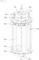
- the combined reformer according to the first embodiment of the present disclosure includes a main body 100, a first catalyst tube 200, a first distributor 300, a second catalyst tube 400, a combustion section 500, a second distributor 600, and a synthesis gas discharge section 700.
- the main body 100 may be formed in a cylindrical shape, defining the overall appearance of the combined reformer and providing an internal cylindrical space, but is not limited thereto.
- the main body 100 is equipped inside thereof with two or more catalyst tubes that react at different temperatures.
- the main body 100 is equipped with a plurality of first catalyst tubes 200 reacting at a first temperature (T1) and a plurality of second catalyst tubes 400 that react at a second temperature (T2) higher than the first temperature (T1).
- the first temperature (T1) and the second temperature (T2) may be set differently depending on the reactions occurring in the first catalyst tubes 200 and the second catalyst tubes 400.
- the description is focused on the situation where the first catalyst tubes 200 are supplied with a hydrocarbon gas containing hydrocarbons with carbon numbers of 2 or more along with steam.
- the hydrocarbons with carbon numbers of 2 or more undergo reforming with steam resulting in their conversion into methane.
- This methane then proceeds to undergo reforming with steam in the second catalyst tubes 400 leading to its conversion into synthesis gas, which includes hydrogen and carbon monoxide.
- the first temperature (T1) which is the reaction temperature of the first catalyst tubes 200, may range from approximately 350°C to 550°C.
- a catalyst that possesses the capability to reform hydrocarbons with carbon numbers of 2 or more is utilized in the first catalyst tubes 200.
- a nickel-based catalyst using MgO or Al 2 O 3 or a combination thereof as a support material may be applied to the first catalyst tubes 200.
- high-grade hydrocarbons with carbon numbers of 2 or more such as ethane, propane, and butane may be converted into methane, carbon monoxide, and hydrogen through reaction formulas (1) and (2).
- the second catalyst tubes 400 operates at a reaction temperature ranging from approximately 700°C to 900°C, the second temperature (T2).
- a catalyst capable of reforming methane is applied in the second catalyst tubes 400.
- a nickel-based catalyst may also be applied to the second catalyst tube 400.
- methane may be converted into synthesis gas (syngas) containing hydrogen and carbon monoxide through reaction formula (3).
- the plurality of first catalyst tubes 200 and the plurality of second catalyst tubes 400 are connected through the first distributor 300, allowing the hydrocarbon gas and steam supplied to the plurality of first catalyst tubes 200 to be distributed and sequentially flow through the plurality of second catalyst tubes 400 via the first distributor 300.
- the gas and steam discharged from the plurality of first catalyst tubes 200 through the first distributor 300 may be uniformly supplied to the plurality of second catalyst tubes 400, and the detailed configuration thereof will be made in detail later.
- the hydrocarbon gas supplied to the first catalyst tubes 200 may be reformed into synthesis gas through steam reforming reactions while flowing through the first catalyst tubes 200 and the second catalyst tubes 400 in sequence. That is, the high-grade hydrocarbons with carbon numbers of 2 or more may be converted into methane in the first catalyst tubes 200, and the methane converted in the first catalyst tubes 200 may be introduced into the second catalyst tubes 400 and further converted into synthesis gas containing hydrogen and carbon monoxide.
- the hydrocarbon gas supplied to the first catalyst tubes 200 may be a pyrolysis gas generated by the pyrolysis of waste materials.
- it may be a pyrolysis gas generated by the pyrolysis of waste plastics, which contains a large amount of hydrocarbons of carbon numbers of 2 or more.
- a combustion section 500 is installed to supply heat to the plurality of first catalyst tubes 200 and the plurality of second catalyst tubes 400 as shown in the drawing.
- the combustion section 500 combusts the hydrocarbon gas, generating combustion gases.
- the generated combustion gases are provided through the central part of the main body 100.
- the combined reformer according to the present disclosure is designed such that for the combustion gases discharged from the combustion section 500 to supply heat to the plurality of second catalyst tubes 400 before supplying heat to the plurality of first catalyst tubes 200.
- the plurality of second catalyst tubes 400 are positioned on the inner side of the radius direction of the main body 100 compared to the plurality of first catalyst tubes 200. In other words, the plurality of second catalyst tubes 400 may be disposed radially more inwardly than the plurality of first catalyst tubes 200 in the main body 100.
- the configuration is not limited thereto, and it is also possible, according to an embodiment, for the combustion gases to supply heat to the plurality of second catalyst tubes 400 after supplying heat to the plurality of first catalyst tubes 200, by positioning the plurality of first catalyst tubes 200 on the inner side of the radius direction of the main body 100 compared to the plurality of second catalyst tubes 400.
- the plurality of first catalyst tubes 200 may be arranged at intervals along the circumferential direction of the main body 100 in the main body 100.
- each of the plurality of first catalyst tubes 200 may be disposed spaced apart in the circumferential direction from each other with a same distance.
- the plurality of second catalyst tubes 400 may be also arranged at intervals along the circumferential direction of the main body 100, on the inner side of the radius direction of the plurality of first catalyst tubes 200 (i.e., arranged radially more inwardly than the first catalyst tubes 200).
- Each of the plurality of second catalyst tubes 400 also may be disposed spaced apart in the circumferential direction from each other with a same distance.
- the number of the plurality of first catalyst tubes 200 and the plurality of second catalyst tubes 400 may be adjusted depending on factors such as the size of the reformer. Both the plurality of first catalyst tubes 200 and the plurality of second catalyst tubes 400 may extend vertically along the longitudinal direction of the main body 100.
- each of the plurality of first catalyst tubes 200 may be formed in a U-shape.
- each of the plurality of first catalyst tubes 200 may extend vertically from the upper side of the combined reformer (may be referred to as a first section of the first catalyst tubes 200), then is connected to a U-turn section 220 (may be referred to as a second section of the first catalyst tubes 200), and extend vertically again toward the upper side (may be referred to as a third section of the first catalyst tubes 200).
- each U-shaped first catalyst tube 200 may be extended along the longitudinal and circumferential direction of the main body 100.
- the first section and the third section of the first catalyst tubes 200 may be extended in the longitudinal direction and the second section of the first catalyst tubes 200 may be extended generally in the circumferential direction.
- Each U-shaped first catalyst tube 200 is provided with a preheating section 202 where the pre-reforming hydrocarbon gas flows parallel to combustion gas and is heated, and a catalyst reforming section 204 where the catalytic reforming occurs.
- the preheating section 202 may be located in one of the straight sections of the U-shaped tube, while the catalyst reforming section 204 may be located in the other straight section of the U-shaped tube. That is, the catalytic material may be filled only in the straight section corresponding to the catalyst reforming section 204 of the U-shaped first catalyst tube 200.
- the preheating section 202 and the catalyst reforming section 204 correspond to the first section and third section of the first catalyst tubes 200, respectively.
- first wall 120 that guides the flow of the combustion gases discharged from the combustion section 500 to effectively supply heat to the plurality of first catalyst tubes 200 and the plurality of second catalyst tubes 400.
- the first wall 120 is positioned between the plurality of first catalyst tubes 200 and the plurality of second catalyst tubes 400, extending vertically upwards from the lower part of the main body 100.
- the combustion gases discharged from the combustion section 500 may flow upwards in the inside of the first wall 120, supplying heat to the plurality of second catalyst tubes 400, and the slightly cooled combustion gases may flow downwards outside of the first wall 120 and inside the main body 100, supplying heat to the plurality of first catalyst tubes 200.
- the combustion gases discharged from the combustion section 500 may flow upwards from the bottom the body of the main body 100, return its flow direction around the upward end of the first wall 120 and then flow downwards toward the bottom of the main body.
- the combustion gases After supplying heat to the plurality of first catalyst tubes 200 and the plurality of second catalyst tubes 400, the combustion gases are discharged to the outside of the main body 100.
- FIG. 5 shows the temperature changes of combustion gas and hydrocarbon gas as hydrocarbon gas passes through the preheating section 202 and the catalyst reforming section 204.
- Preheating the hydrocarbon gases in the preheating section 202 to a temperature close to the catalytic reaction temperature range allows for immediate catalytic reforming reaction in the catalyst reforming section 204, maximizing heat absorption from the combustion gases and increasing the reforming efficiency. As shown in FIG.
- the combined reformer may be configured such that the temperature of the combustion gas flowing between the first wall 120 and the main body 100 becomes lower toward and is lowest at the bottom of the first catalyst tubes 200. Furthermore, the lowest temperature of the combustion gas at the bottom of the first catalyst tubes 200 may be within the temperature range (T1) for the catalytic reaction of the first catalyst tubes 200.
- each of the plurality of second catalyst tubes 400 may extend vertically from the upper side of the main body 100 (may be referred to as a first section of the second catalyst tubes 400), then pass through a U-turn section 420 (may be referred to as a second section of the second catalyst tubes 400), and extend vertically again toward the upper side (may be referred to as a third section of the second catalyst tubes 400).
- each U-shaped second catalyst tube 400 may be extended along the longitudinal and circumferential direction of the main body 100. In other words, the first section and the third section of the second catalyst tubes 400 may be extended in the longitudinal direction.
- the second section of the second catalyst tubes 400 may be extended in a radial direction of the main body 100.
- the number of U-turn sections 420 may be adjusted based on the required reaction time of the catalyst. As the required reaction time of the catalyst increases, the number of U-turn sections 420 may be increased.
- the first distributor 300 is connected to the discharge end of the plurality of first catalyst tubes 200 and the inlet end of the plurality of second catalyst tubes 400.
- the first distributor 300 may be formed in a donut shape or in a torus shape, with a first chamber 320 inside that fluidly communicates with and connects the discharge end of the plurality of first catalyst tubes 200 and the inlet end of the plurality of second catalyst tubes 400. This allows gases and steam discharged from the plurality of first catalyst tubes 200 to gather in the first chamber 320 and be uniformly supplied to the plurality of second catalyst tubes 400.
- a synthesis gas discharge section 700 may be arranged on the inner side of the radial direction of the first distributor 300.
- the synthesis gas discharge section 700 is connected to the discharge end of the plurality of second catalyst tubes 400 and serves for the discharge of synthesis gas. Since the second catalyst tubes 400 have a U-turn section 420 (i.e., the second section of the second catalyst tubes 400) extending in the radial direction of the main body 100, it is preferable for the synthesis gas discharge section 700 to be formed on the inner side of the radial direction of the first distributor 300, allowing for a more compact structural configuration of the combined reformer.
- the synthesis gas discharge section 700 may include a third chamber 720 that collects the synthesis gas by connecting to the discharge ends of the plurality of second catalyst tubes 400, and a discharge pipe 740 within the third chamber 720 that releases the collected synthesis gas to the outside.
- the combined reformer also includes a second distributor 600, which serves for distributing the hydrocarbon gas and steam supplied to the plurality of first catalyst tubes 200.
- the second distributor 600 may be positioned on the same side as the first distributor 300 with respect to the main body 100, in terms of its radial position.
- the combustion section 500 is located on the opposite side of the first distributor 300 and the second distributor 600 with respective to the main body 100 in the longitudinal direction.
- the first distributor 300 and the second distributor 600 may be disposed at the top of the main body 100 and the combustion section 500 may be disposed at the bottom of the main body.
- the second distributor 600 may be disposed directly above the first distributor 300 having a similar or a same shape with the first distributor 300, with a second chamber 620 inside thereof.
- the second distributor 600 includes one or more supply ports 640 for supplying (i.e., receiving) hydrocarbon gas and steam, and a second chamber 620 connected to the inlet ends of the plurality of first catalyst tubes 200. Accordingly, the hydrocarbon gas and steam supplied from one or more supply ports 640 are gathered in the second chamber 620 and evenly supplied to a plurality of first catalyst tubes 200.
- the synthesis gas discharge section 700 may extend through the inner side of the radial direction of the second distributor 600.
- the third chamber 720 of the synthesis gas discharge section 700 extends through the inner side of the second distributor 600 and the inner side of the first distributor 300, resulting in a structure where the third chamber 720 is formed at the center and surrounded by the first chamber 320 and the second chamber 620.
- the synthesis gas discharge section 700 may be in a cylindrical shape.
- the combined reformer has been described as including both the first distributor 300 and the second distributor 600 in this embodiment, it is also possible to include only the first distributor 300 or only the second distributor 600 according to an embodiment.
- the first catalyst tubes 200 may be supplied with hydrocarbon gas (e.g., biogas) and steam, the hydrocarbon gas containing methane and carbon dioxide.
- hydrocarbon gas e.g., biogas
- steam the hydrocarbon gas containing methane and carbon dioxide.
- reaction formula (3) When biogas and steam are supplied to the first catalyst tubes 200, methane reacts with steam according to reaction formula (3) to reform into synthesis gas containing hydrogen and carbon monoxide (wet reforming), while methane may be reformed into synthesis gas containing hydrogen and carbon monoxide by reacting with carbon dioxide according to reaction formula (4) in the second catalyst tubes 400 (dry reforming).
- reaction formula (3) ------- CH 4 + H 2 O ⁇ CO + 3H 2
- reaction formula (4) ------- CH 4 + CO 2 ⁇ 2 CO + 2H 2
- the first catalyst tube 200 may have a reaction temperature, denoted as the first temperature (T1), ranging from about 450°C to 650°C, and a catalyst suitable for wet reforming of methane may be applied.
- the second catalyst tube 400 may have a reaction temperature, denoted as the second temperature (T2), ranging from about 650°C to 850°C, and a catalyst suitable for dry reforming of methane may be applied.
- the wet reforming reaction of methane is described as occurring in the first catalyst tubes 200, it is possible that some of the reforming reaction may also occur in the second catalyst tubes 400, as the wet reforming of methane can occur over a wide temperature range.
- the hydrocarbon gas in this case, biogas containing methane and carbon dioxide
- steam may flow sequentially through the first catalyst tubes 200 and the second catalyst tubes 400, undergoing both wet reforming and dry reforming reactions to be converted into synthesis gas.
- a separate carbon dioxide removal device is not required because carbon dioxide does not need to be removed from biogas before the biogas is supplied to the reformer.
- carbon dioxide can be supplied to the reformer as a part of the biogas.
- the hydrocarbon gas (biogas) passing through the preheating section 202 may flow in the same direction as the combustion gas, and the hydrocarbon gas (biogas) passing through the catalyst reforming section 204 may flow in the opposite direction to the combustion gas.
- the combined reformer may be configured such that the hydrocarbon gas (biogas) is preheated to a temperature close to the temperature range required for the catalytic reaction when reaching the catalyst reforming section 204, and thus, the catalytic reforming reaction may immediately occur when the hydrocarbon gas (biogas) reaches the catalyst reforming section 204, maximizing the heat absorption from the combustion gas and enhancing the reforming efficiency.
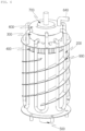
- the combined reformer in the second embodiment includes the same components as the combined reformer in the first embodiment and may additionally incorporate a spiral guide plate 900 that passes through the plurality of first catalyst tubes 200 to guide the combustion gas.
- the guide plate 900 may be formed as a spiral plate surrounding the first wall 120 to guide the combustion gas flowing downward between the first wall 120 and the main body 100 and may accommodate the insertion of the plurality of first catalyst tubes 200.
- the guide plate 900 may have penetration holes provided to accommodate the plurality of first catalyst tubes 200, and the first catalyst tubes 200 may be securely fixed to the penetration holes by welding after being inserted into the penetration holes.
- the coupling of the plurality of first catalyst tubes 200 to a single guide plate 900 may make it challenging to access and repair the first catalyst tubes, when necessary.
- the guide plate 900 may be composed of a plurality of sub-plates 900a divided for each U-shaped first catalyst tube 200 passing through, as shown in FIG. 7 . That is, one of the sub-plates 900a are installed for each U-shaped first catalyst tube 200 to collectively form a spiral plate that enclose the entire first wall 120. In this case, it is preferable to minimize the distance between adjacent sub-plates 900a.
- the combined reformer of the third embodiment is identical to the combined reformer of the first embodiment, except for the addition of fins on the outer surface of the plurality of first catalyst tubes 200 in the longitudinal direction.
- spiral fins 242 may be provided on the outer surface of the first catalyst tubes 200 along the longitudinal direction, especially, on the outer surface of the first and third sections of the first catalyst tubes 200.
- the configuration is not limited to thereto, and the shape of the fins may vary.
- a plurality of fins 244 may be aligned parallel to each other on the outer surface of the first catalyst tubes 200 in the longitudinal direction, each fin 244 being in an elongated shape in the longitudinal direction, as shown in FIG. 9 .
- the increased heat transfer surface area of the first catalyst tubes 200 facilitates heat exchange with the combustion gas, allowing for more efficient heat absorption and improved reforming efficiency.
- different reforming reactions can be continuously conducted by supplying heat from the combustion gas to two or more catalyst tubes, which react at different temperatures, in sequence.
- hydrocarbons with carbon numbers of 2 or more may be reformed into methane by reacting with steam, and methane may be reformed into synthesis gas by reacting with steam.
- the structure and process can be simplified because a separate pre-reformer does not need to be installed.
- methane may be reformed into synthesis gas by reacting with steam (wet reforming) and methane may be reformed into synthesis gas by reacting with carbon dioxide (dry reforming) at the same time.
- the combined reactor is configured to adjust the combustion section 500 such that the temperature of the combustion gas at the bottom of the first catalyst tubes 200 between the first wall 120 and the main body 100 is within the first temperature range (T1) for the reaction of the first catalyst tubes 200 depending on the supply gas to the first catalyst tubes 200, the supply gas being either a combination of pyrolysis gas (containing hydrocarbons with carbon numbers of 2 or more) and steam or a combination of biogas (i.e., containing including hydrocarbon gas containing methane and carbon dioxide) and steam.
- T1 first temperature range
- the gas and steam discharged from a plurality of first catalyst tubes can be effectively distributed to multiple second catalyst tubes and may be evenly supplied to multiple second catalyst tubes.
- the first distributor helps maintain a balanced distribution of gases and steam, optimizing the performance of the overall process.
- the hydrocarbon gas and steam supplied to multiple first catalyst tubes can be evenly distributed and supplied to multiple first catalyst tubes.
- the second distributor aids in achieving a balanced distribution of the hydrocarbon gas and steam, which helps optimize the performance and effectiveness of the first catalyst tubes throughout the process.
- the first catalyst tube in a U-shape, with a preheating section where the hydrocarbon gas flows parallel to the combustion gas and is preheated before reformation, and a catalyst reforming section where catalytic reforming takes place, it is possible to maximizes the heat absorption from the combustion gas, leading to improvement in reforming efficiency.
Landscapes
- Chemical & Material Sciences (AREA)
- Chemical Kinetics & Catalysis (AREA)
- Organic Chemistry (AREA)
- Health & Medical Sciences (AREA)
- General Health & Medical Sciences (AREA)
- Engineering & Computer Science (AREA)
- Combustion & Propulsion (AREA)
- Inorganic Chemistry (AREA)
- Physics & Mathematics (AREA)
- Thermal Sciences (AREA)
- Hydrogen, Water And Hydrids (AREA)
Abstract
Description
- The present application claims priority to
Korean Patent Applications No. 10-2022-0088495, filed July 18, 2022 No. 10-2023-0079217, filed June 20, 2023 - The present disclosure relates to a combined reformer, and more particularly, to a combined reformer capable of continuously performing different reforming reactions by supplying heat from the combustion gas to two or more catalyst tubes, which react at different temperatures, in sequence.
- The conventional Steam Methane Reforming (SMR) facility, used for reforming natural gas with methane (CH4) as the main component, has the complexity issue in terms of structure and process. This is mainly because an extra pre-reformer is necessary to convert gases containing higher carbon content hydrocarbons (CxHy) into methane before the reforming process can take place.
- In addition, even when biogas needs to be reformed, since carbon dioxide contained in biogas must be removed and then supplied to the steam methane reforming facility, there is a problem that a separate facility for removing carbon dioxide is required.
- The present disclosure aims to provide a combined reformer capable of continuously performing different reforming reactions by sequentially supplying heat from the combustion gas to the two or more catalyst tubes that react at different temperatures.
- Also, the present disclosure aims to provide a combined reformer capable of enhancing the reforming efficiency with a U-shaped first catalyst tube including a preheating section where the hydrocarbon gas is preheated, flowing parallel to the combustion gas, and a catalyst reforming section where the catalytic reforming takes place.
- The technical objects of the present disclosure are not limited to the aforesaid, and other objects not described herein which can be clearly understood by those skilled in the art from the descriptions below.
- In order to accomplish the above objects, a combined reformer according to an embodiment of the present disclosure includes a main body, a plurality of first catalyst tubes arranged inside the main body and configured to act at a first temperature, a plurality of second catalyst tubes arranged inside the main body, fluidly connected to the plurality of first catalyst tubes, and configured to react at a second temperature higher than the first temperature, a combustion section configured to supply heat to the plurality of first catalyst tubes and the plurality of second catalyst tubes, and a first distributor connecting the plurality of first catalyst tubes and the plurality of second catalyst tubes and configured to distribute gas and steam discharged from the plurality of first catalyst tubes to the plurality of second catalyst tubes. According to an embodiment, the plurality of first catalyst tubes are formed in a U-shape and each U-shaped first catalyst tube is provided with a preheating section where pre-reforming hydrocarbon gas flows parallel to combustion gas and is heated and a catalyst reforming section where the catalytic reforming takes place.
- According to an embodiment, the preheating section may be located in one of the straight sections of the U-shaped tube, and the catalyst reforming section may be located in the other straight section of the U-shaped tube.
- According to an embodiment, the plurality of first catalyst tubes are configured such that the hydrocarbon gas may flow in the same direction with a flow direction of the combustion gas in the preheating section and the hydrocarbon gas flows in the opposite direction to the flow direction of the combustion gas in the catalyst reforming section.
- According to an embodiment, the first distributor may include a first chamber connecting discharge ends of the plurality of first catalyst tubes and inlet ends of the plurality of second catalyst tubes. According to an embodiment, the first distributor is in a torus shape.
- According to an embodiment, the combined reformer may further include a synthesis gas discharge section arranged on the inner side in the radial direction of the first distributer, accommodating the connection of discharge ends of the plurality of second catalyst tubes to discharge synthesis gas.
- According to an embodiment, the combined reformer may further include a second distributor distributing the hydrocarbon gas and steam supplied to the plurality of first catalyst tube, wherein the second distributor may be arranged on the same side as the first distributor with respect to the main body.
- According to an embodiment, the second distributor may include one or more supply ports supplying the hydrocarbon gas and steam and a second chamber connected to inlet ends of the plurality of first catalyst tubes.
- According to an embodiment, the synthesis gas discharge section may extend through the inner side in the radial direction of the second distributor.
- According to an embodiment, the combustion section may be arranged on the opposite side of the first distributor and the second distributor with respect to the main body.
- According to an embodiment, each U-shaped first catalyst tube may extend along the longitudinal and circumferential directions of the main body.
- According to an embodiment, the combined reformer may further include a spiral guide plate passing through the plurality of first catalyst tubes to guide the combustion gas.
- According to an embodiment, wherein the plurality of first catalyst tubes may be inserted through the guide plate.
- According to an embodiment, the guide plate may be composed of a plurality of sub-plates, divided at each section passing through each U-shaped first catalyst tube.
- According to an embodiment, the plurality of first catalyst tubes may include fins provided on the outer surface thereof in the longitudinal direction.
- According to an embodiment, the hydrocarbon gas suppled to the plurality of first catalyst tubes may include hydrocarbons with a carbon number of 2 or more, which may be reformed into methane by reacting with the steam in the plurality of first catalyst tubes, the methane being reformed into synthesis gas including hydrogen and carbon monoxide by reacting with the steam in the plurality of second catalyst tubes.
- According to an embodiment, the hydrocarbon gas suppled to the plurality of first catalyst tubes may include methane and carbon dioxide, the methane being reformed into synthesis gas including hydrogen and carbon monoxide by reacting with the steam in the plurality of first catalyst tubes and by reacting with the carbon dioxide in the plurality of second catalyst tubes.
- In order to accomplish the above objects, a combined reformer according to another embodiment of the present disclosure may include a main body, a plurality of first catalyst tubes arranged inside the main body and configured to react at a first temperature, a plurality of second catalyst tubes arranged inside the main body, connected to the plurality of first catalyst tubes, and configured to react at a second temperature higher than the first temperature, a combustion section configured to supply heat to the plurality of first catalyst tubes and the plurality of second catalyst tubes, a second distributor distributing hydrocarbon gas and steam supplied to the plurality of first catalyst tubes. According to an embodiment the plurality of first catalyst tubes are formed in a U-shape and each U-shaped first catalyst tube is provided with a preheating section where pre-reforming hydrocarbon gas flows parallel to combustion gas and is heated and a catalyst reforming section where the catalytic reforming takes place.
-
-
FIG. 1 is a front view illustrating a combined reformer of the first embodiment of the present disclosure; -
FIG. 2 is a perspective view of the combined reformer ofFIG. 1 , with the omission of the main body; -
FIG. 3 is a cross-sectional view taken along the A-A' line inFIG. 2 ; -
FIG. 4 is a cross-sectional view taken along the B-B' line inFIG. 3 ; -
FIG. 5 is a graph representing temperature changes of combustion gas and hydrocarbon gas as the hydrocarbon gas passes through a preheating section and a catalyst reforming section of a first catalyst tube; -
FIG. 6 is a perspective view illustrating a combined reformer according to a second embodiment of the present disclosure, with the omission of the main body; -
FIG. 7 is a perspective view of an alternative embodiment ofFIG. 6 ; -
FIG. 8 is a perspective view illustrating a combined reformer according to the third embodiment of the present disclosure, with the omission of the main body; and -
FIG. 9 is a perspective view of an alternative embodiment ofFIG. 8 . - Hereinafter, preferred embodiments of the combined reformer of the present disclosure will be described with reference to the accompanying drawings.
- The following terms are defined in consideration of the functionality in the present disclosure and may vary according to the intention or convention of a user or an operator, and thus, the following embodiments are merely illustrative examples of the components recited in the claims of the present disclosure, and do not limit the scope of the invention.
- To provide a clear explanation of the present disclosure, irrelevant parts have been omitted, and throughout the specification, the same or similar components are denoted by the same reference numerals. Throughout the specification, when a part is said to "comprise" a certain component, this does not mean that other components are excluded, but that other components may be additionally included, unless there is a specific indication to the contrary.
- First, a description is made of the combined reformer according to the first embodiment of the present disclosure with reference to
FIGS. 1 to 5 . - The combined reformer according to the first embodiment of the present disclosure includes a
main body 100, afirst catalyst tube 200, afirst distributor 300, asecond catalyst tube 400, acombustion section 500, asecond distributor 600, and a synthesisgas discharge section 700. - According to an embodiment, the
main body 100 may be formed in a cylindrical shape, defining the overall appearance of the combined reformer and providing an internal cylindrical space, but is not limited thereto. - The
main body 100 is equipped inside thereof with two or more catalyst tubes that react at different temperatures. In detail, themain body 100 is equipped with a plurality offirst catalyst tubes 200 reacting at a first temperature (T1) and a plurality ofsecond catalyst tubes 400 that react at a second temperature (T2) higher than the first temperature (T1). The first temperature (T1) and the second temperature (T2) may be set differently depending on the reactions occurring in thefirst catalyst tubes 200 and thesecond catalyst tubes 400. - In this embodiment, the description is focused on the situation where the
first catalyst tubes 200 are supplied with a hydrocarbon gas containing hydrocarbons with carbon numbers of 2 or more along with steam. In thesefirst catalyst tubes 200, the hydrocarbons with carbon numbers of 2 or more undergo reforming with steam resulting in their conversion into methane. This methane then proceeds to undergo reforming with steam in thesecond catalyst tubes 400 leading to its conversion into synthesis gas, which includes hydrogen and carbon monoxide. - The first temperature (T1), which is the reaction temperature of the
first catalyst tubes 200, may range from approximately 350°C to 550°C. A catalyst that possesses the capability to reform hydrocarbons with carbon numbers of 2 or more is utilized in thefirst catalyst tubes 200. For example, a nickel-based catalyst using MgO or Al2O3 or a combination thereof as a support material may be applied to thefirst catalyst tubes 200. As a result, in thefirst catalyst tubes 200, high-grade hydrocarbons with carbon numbers of 2 or more, such as ethane, propane, and butane may be converted into methane, carbon monoxide, and hydrogen through reaction formulas (1) and (2).
Reaction formula (1) ------- CnHm + nH2O → nCO + (n+m/2)H2
Reaction formula (2) ------- CO + 3H2 → CH4 + H2O
- The
second catalyst tubes 400 operates at a reaction temperature ranging from approximately 700°C to 900°C, the second temperature (T2). A catalyst capable of reforming methane is applied in thesecond catalyst tubes 400. For example, a nickel-based catalyst may also be applied to thesecond catalyst tube 400. As a result, in thesecond catalyst tube 400, methane may be converted into synthesis gas (syngas) containing hydrogen and carbon monoxide through reaction formula (3). - €
Reaction formula (3) ------- CH4 + H2O → CO + 3H2
- While the wet reforming reaction of methane is primarily described as taking place in the
second catalyst tube 400, it is indeed possible for some of the reaction to occur in thefirst catalyst tube 200. This is because the wet reforming of methane can occur across a wide temperature range including the temperature range of the first catalyst tube. Therefore, some degree of methane wet reforming might occur in both catalyst tubes, although the majority of the reaction is expected to happen in thesecond catalyst tubes 400. - The plurality of
first catalyst tubes 200 and the plurality ofsecond catalyst tubes 400 are connected through thefirst distributor 300, allowing the hydrocarbon gas and steam supplied to the plurality offirst catalyst tubes 200 to be distributed and sequentially flow through the plurality ofsecond catalyst tubes 400 via thefirst distributor 300. Here, the gas and steam discharged from the plurality offirst catalyst tubes 200 through thefirst distributor 300 may be uniformly supplied to the plurality ofsecond catalyst tubes 400, and the detailed configuration thereof will be made in detail later. - Accordingly, even though the hydrocarbon gas supplied to the
first catalyst tubes 200 contains a large amount of hydrocarbons with carbon numbers of 2 or more, it may be reformed into synthesis gas through steam reforming reactions while flowing through thefirst catalyst tubes 200 and thesecond catalyst tubes 400 in sequence. That is, the high-grade hydrocarbons with carbon numbers of 2 or more may be converted into methane in thefirst catalyst tubes 200, and the methane converted in thefirst catalyst tubes 200 may be introduced into thesecond catalyst tubes 400 and further converted into synthesis gas containing hydrogen and carbon monoxide. Particularly, according to an embodiment, the hydrocarbon gas supplied to thefirst catalyst tubes 200 may be a pyrolysis gas generated by the pyrolysis of waste materials. For example, it may be a pyrolysis gas generated by the pyrolysis of waste plastics, which contains a large amount of hydrocarbons of carbon numbers of 2 or more. - At the lower center of the
main body 100, acombustion section 500 is installed to supply heat to the plurality offirst catalyst tubes 200 and the plurality ofsecond catalyst tubes 400 as shown in the drawing. According to embodiment, thecombustion section 500 combusts the hydrocarbon gas, generating combustion gases. The generated combustion gases are provided through the central part of themain body 100. - Because the
second catalyst tubes 400 react at a higher temperature than thefirst catalyst tubes 200, it may be effective that the combined reformer according to the present disclosure is designed such that for the combustion gases discharged from thecombustion section 500 to supply heat to the plurality ofsecond catalyst tubes 400 before supplying heat to the plurality offirst catalyst tubes 200. To achieve this, the plurality ofsecond catalyst tubes 400 are positioned on the inner side of the radius direction of themain body 100 compared to the plurality offirst catalyst tubes 200. In other words, the plurality ofsecond catalyst tubes 400 may be disposed radially more inwardly than the plurality offirst catalyst tubes 200 in themain body 100. - However, the configuration is not limited thereto, and it is also possible, according to an embodiment, for the combustion gases to supply heat to the plurality of
second catalyst tubes 400 after supplying heat to the plurality offirst catalyst tubes 200, by positioning the plurality offirst catalyst tubes 200 on the inner side of the radius direction of themain body 100 compared to the plurality ofsecond catalyst tubes 400. - In detail, as shown in
FIGS. 2 and4 , the plurality offirst catalyst tubes 200 may be arranged at intervals along the circumferential direction of themain body 100 in themain body 100. In other words, each of the plurality offirst catalyst tubes 200 may be disposed spaced apart in the circumferential direction from each other with a same distance. Likewise, the plurality ofsecond catalyst tubes 400 may be also arranged at intervals along the circumferential direction of themain body 100, on the inner side of the radius direction of the plurality of first catalyst tubes 200 (i.e., arranged radially more inwardly than the first catalyst tubes 200). Each of the plurality ofsecond catalyst tubes 400 also may be disposed spaced apart in the circumferential direction from each other with a same distance. The number of the plurality offirst catalyst tubes 200 and the plurality ofsecond catalyst tubes 400 may be adjusted depending on factors such as the size of the reformer. Both the plurality offirst catalyst tubes 200 and the plurality ofsecond catalyst tubes 400 may extend vertically along the longitudinal direction of themain body 100. - Here, each of the plurality of
first catalyst tubes 200 may be formed in a U-shape. In detail, each of the plurality offirst catalyst tubes 200 may extend vertically from the upper side of the combined reformer (may be referred to as a first section of the first catalyst tubes 200), then is connected to a U-turn section 220 (may be referred to as a second section of the first catalyst tubes 200), and extend vertically again toward the upper side (may be referred to as a third section of the first catalyst tubes 200). As shown inFIGS. 2 and4 , each U-shapedfirst catalyst tube 200 may be extended along the longitudinal and circumferential direction of themain body 100. In other words, the first section and the third section of thefirst catalyst tubes 200 may be extended in the longitudinal direction and the second section of thefirst catalyst tubes 200 may be extended generally in the circumferential direction. - Each U-shaped
first catalyst tube 200 is provided with apreheating section 202 where the pre-reforming hydrocarbon gas flows parallel to combustion gas and is heated, and acatalyst reforming section 204 where the catalytic reforming occurs. As shown inFIG. 2 , the preheatingsection 202 may be located in one of the straight sections of the U-shaped tube, while thecatalyst reforming section 204 may be located in the other straight section of the U-shaped tube. That is, the catalytic material may be filled only in the straight section corresponding to thecatalyst reforming section 204 of the U-shapedfirst catalyst tube 200. The preheatingsection 202 and thecatalyst reforming section 204 correspond to the first section and third section of thefirst catalyst tubes 200, respectively. - Inside the
main body 100, there is afirst wall 120 that guides the flow of the combustion gases discharged from thecombustion section 500 to effectively supply heat to the plurality offirst catalyst tubes 200 and the plurality ofsecond catalyst tubes 400. Thefirst wall 120 is positioned between the plurality offirst catalyst tubes 200 and the plurality ofsecond catalyst tubes 400, extending vertically upwards from the lower part of themain body 100. As a result, the combustion gases discharged from thecombustion section 500 may flow upwards in the inside of thefirst wall 120, supplying heat to the plurality ofsecond catalyst tubes 400, and the slightly cooled combustion gases may flow downwards outside of thefirst wall 120 and inside themain body 100, supplying heat to the plurality offirst catalyst tubes 200. In other words, the combustion gases discharged from thecombustion section 500 may flow upwards from the bottom the body of themain body 100, return its flow direction around the upward end of thefirst wall 120 and then flow downwards toward the bottom of the main body. After supplying heat to the plurality offirst catalyst tubes 200 and the plurality ofsecond catalyst tubes 400, the combustion gases are discharged to the outside of themain body 100. - As a result, the hydrocarbon gas passing through the
preheating section 202 of the U-shapedfirst catalyst tube 200 flows in the same direction between thefirst wall 120 and themain body 100 as the combustion gas does, while the hydrocarbon gas passing through thecatalyst reforming section 204 flows in the opposite direction to the combustion gas between thefirst wall 120 and themain body 100.FIG. 5 shows the temperature changes of combustion gas and hydrocarbon gas as hydrocarbon gas passes through thepreheating section 202 and thecatalyst reforming section 204. Preheating the hydrocarbon gases in thepreheating section 202 to a temperature close to the catalytic reaction temperature range allows for immediate catalytic reforming reaction in thecatalyst reforming section 204, maximizing heat absorption from the combustion gases and increasing the reforming efficiency. As shown inFIG. 5 , the combined reformer may be configured such that the temperature of the combustion gas flowing between thefirst wall 120 and themain body 100 becomes lower toward and is lowest at the bottom of thefirst catalyst tubes 200. Furthermore, the lowest temperature of the combustion gas at the bottom of thefirst catalyst tubes 200 may be within the temperature range (T1) for the catalytic reaction of thefirst catalyst tubes 200. - Similarly, the plurality of
second catalyst tubes 400 are also formed in a U-shape. In detail, each of the plurality ofsecond catalyst tubes 400 may extend vertically from the upper side of the main body 100 (may be referred to as a first section of the second catalyst tubes 400), then pass through a U-turn section 420 (may be referred to as a second section of the second catalyst tubes 400), and extend vertically again toward the upper side (may be referred to as a third section of the second catalyst tubes 400). As shown inFIG. 3 , each U-shapedsecond catalyst tube 400 may be extended along the longitudinal and circumferential direction of themain body 100. In other words, the first section and the third section of thesecond catalyst tubes 400 may be extended in the longitudinal direction. According to an embodiment, the second section of thesecond catalyst tubes 400 may be extended in a radial direction of themain body 100. The number ofU-turn sections 420 may be adjusted based on the required reaction time of the catalyst. As the required reaction time of the catalyst increases, the number ofU-turn sections 420 may be increased. - As shown in
FIGS. 2 and3 , thefirst distributor 300 is connected to the discharge end of the plurality offirst catalyst tubes 200 and the inlet end of the plurality ofsecond catalyst tubes 400. In detail, thefirst distributor 300 may be formed in a donut shape or in a torus shape, with afirst chamber 320 inside that fluidly communicates with and connects the discharge end of the plurality offirst catalyst tubes 200 and the inlet end of the plurality ofsecond catalyst tubes 400. This allows gases and steam discharged from the plurality offirst catalyst tubes 200 to gather in thefirst chamber 320 and be uniformly supplied to the plurality ofsecond catalyst tubes 400. - Additionally, on the inner side of the radial direction of the
first distributor 300, a synthesisgas discharge section 700 may be arranged. The synthesisgas discharge section 700 is connected to the discharge end of the plurality ofsecond catalyst tubes 400 and serves for the discharge of synthesis gas. Since thesecond catalyst tubes 400 have a U-turn section 420 (i.e., the second section of the second catalyst tubes 400) extending in the radial direction of themain body 100, it is preferable for the synthesisgas discharge section 700 to be formed on the inner side of the radial direction of thefirst distributor 300, allowing for a more compact structural configuration of the combined reformer. In detail, the synthesisgas discharge section 700 may include athird chamber 720 that collects the synthesis gas by connecting to the discharge ends of the plurality ofsecond catalyst tubes 400, and adischarge pipe 740 within thethird chamber 720 that releases the collected synthesis gas to the outside. - Furthermore, the combined reformer also includes a
second distributor 600, which serves for distributing the hydrocarbon gas and steam supplied to the plurality offirst catalyst tubes 200. In the present disclosure, since thefirst catalyst tubes 200 are formed in a U-shape, as shown inFIG. 2 , thesecond distributor 600 may be positioned on the same side as thefirst distributor 300 with respect to themain body 100, in terms of its radial position. Additionally, thecombustion section 500 is located on the opposite side of thefirst distributor 300 and thesecond distributor 600 with respective to themain body 100 in the longitudinal direction. In other words, thefirst distributor 300 and thesecond distributor 600 may be disposed at the top of themain body 100 and thecombustion section 500 may be disposed at the bottom of the main body. According to an embodiment, thesecond distributor 600 may be disposed directly above thefirst distributor 300 having a similar or a same shape with thefirst distributor 300, with asecond chamber 620 inside thereof. - As shown in
FIGS. 2 and3 , thesecond distributor 600 includes one ormore supply ports 640 for supplying (i.e., receiving) hydrocarbon gas and steam, and asecond chamber 620 connected to the inlet ends of the plurality offirst catalyst tubes 200. Accordingly, the hydrocarbon gas and steam supplied from one ormore supply ports 640 are gathered in thesecond chamber 620 and evenly supplied to a plurality offirst catalyst tubes 200. To achieve a compact structure of the combined reformer, the synthesisgas discharge section 700 may extend through the inner side of the radial direction of thesecond distributor 600. In this embodiment, thethird chamber 720 of the synthesisgas discharge section 700 extends through the inner side of thesecond distributor 600 and the inner side of thefirst distributor 300, resulting in a structure where thethird chamber 720 is formed at the center and surrounded by thefirst chamber 320 and thesecond chamber 620. The synthesisgas discharge section 700 may be in a cylindrical shape. - Although the combined reformer has been described as including both the
first distributor 300 and thesecond distributor 600 in this embodiment, it is also possible to include only thefirst distributor 300 or only thesecond distributor 600 according to an embodiment. - According to an embodiment, the
first catalyst tubes 200 may be supplied with hydrocarbon gas (e.g., biogas) and steam, the hydrocarbon gas containing methane and carbon dioxide. Hereinafter, descriptions are made of the reforming reactions occurring in thefirst catalyst tubes 200 and thesecond catalyst tubes 400 when the biogas and steam are supplied to thefirst catalyst tubes 200. The structure of the combined reformer, excluding the reforming reactions, may be the same as described above. - When biogas and steam are supplied to the
first catalyst tubes 200, methane reacts with steam according to reaction formula (3) to reform into synthesis gas containing hydrogen and carbon monoxide (wet reforming), while methane may be reformed into synthesis gas containing hydrogen and carbon monoxide by reacting with carbon dioxide according to reaction formula (4) in the second catalyst tubes 400 (dry reforming).
Reaction formula (3) ------- CH4 + H2O → CO + 3H2
Reaction formula (4) ------- CH4 + CO2 → 2 CO + 2H2
- In this case, the
first catalyst tube 200 may have a reaction temperature, denoted as the first temperature (T1), ranging from about 450°C to 650°C, and a catalyst suitable for wet reforming of methane may be applied. Thesecond catalyst tube 400 may have a reaction temperature, denoted as the second temperature (T2), ranging from about 650°C to 850°C, and a catalyst suitable for dry reforming of methane may be applied. - Although the wet reforming reaction of methane is described as occurring in the
first catalyst tubes 200, it is possible that some of the reforming reaction may also occur in thesecond catalyst tubes 400, as the wet reforming of methane can occur over a wide temperature range. - In this manner, the hydrocarbon gas (in this case, biogas containing methane and carbon dioxide) and steam may flow sequentially through the
first catalyst tubes 200 and thesecond catalyst tubes 400, undergoing both wet reforming and dry reforming reactions to be converted into synthesis gas. In this case, a separate carbon dioxide removal device is not required because carbon dioxide does not need to be removed from biogas before the biogas is supplied to the reformer. In other words, carbon dioxide can be supplied to the reformer as a part of the biogas. - Similarly, in the U-shaped
first catalyst tube 200, the hydrocarbon gas (biogas) passing through thepreheating section 202 may flow in the same direction as the combustion gas, and the hydrocarbon gas (biogas) passing through thecatalyst reforming section 204 may flow in the opposite direction to the combustion gas. The combined reformer may be configured such that the hydrocarbon gas (biogas) is preheated to a temperature close to the temperature range required for the catalytic reaction when reaching thecatalyst reforming section 204, and thus, the catalytic reforming reaction may immediately occur when the hydrocarbon gas (biogas) reaches thecatalyst reforming section 204, maximizing the heat absorption from the combustion gas and enhancing the reforming efficiency. - Next, a description is made of the combined reformer according to the second embodiment of the present disclosure with reference to
FIG. 6 . - The combined reformer in the second embodiment includes the same components as the combined reformer in the first embodiment and may additionally incorporate a
spiral guide plate 900 that passes through the plurality offirst catalyst tubes 200 to guide the combustion gas. - The
guide plate 900 may be formed as a spiral plate surrounding thefirst wall 120 to guide the combustion gas flowing downward between thefirst wall 120 and themain body 100 and may accommodate the insertion of the plurality offirst catalyst tubes 200. For this purpose, theguide plate 900 may have penetration holes provided to accommodate the plurality offirst catalyst tubes 200, and thefirst catalyst tubes 200 may be securely fixed to the penetration holes by welding after being inserted into the penetration holes. - As a result, as the combustion gas flows downward along the
spiral guide plate 900, traversing through all thefirst catalyst tubes 200, which reduces the heat absorption variation among the plurality of first catalyst tubes and increases the heat absorption capacity of the first catalyst tubes by adjusting the combustion gas velocity through thefirst catalyst tubes 200 and enhancing the external heat transfer coefficient. - However, in this embodiment, the coupling of the plurality of
first catalyst tubes 200 to asingle guide plate 900 may make it challenging to access and repair the first catalyst tubes, when necessary. - To address this issue, in another embodiment, the
guide plate 900 may be composed of a plurality of sub-plates 900a divided for each U-shapedfirst catalyst tube 200 passing through, as shown inFIG. 7 . That is, one of the sub-plates 900a are installed for each U-shapedfirst catalyst tube 200 to collectively form a spiral plate that enclose the entirefirst wall 120. In this case, it is preferable to minimize the distance between adjacent sub-plates 900a. - Next, a description is made of the combined reformer according to the third embodiment of the present disclosure with reference to
FIG. 8 . - The combined reformer of the third embodiment is identical to the combined reformer of the first embodiment, except for the addition of fins on the outer surface of the plurality of
first catalyst tubes 200 in the longitudinal direction. In this embodiment,spiral fins 242 may be provided on the outer surface of thefirst catalyst tubes 200 along the longitudinal direction, especially, on the outer surface of the first and third sections of thefirst catalyst tubes 200. - However, the configuration is not limited to thereto, and the shape of the fins may vary. For example, in another embodiment, a plurality of
fins 244 may be aligned parallel to each other on the outer surface of thefirst catalyst tubes 200 in the longitudinal direction, eachfin 244 being in an elongated shape in the longitudinal direction, as shown inFIG. 9 . - As a result, the increased heat transfer surface area of the
first catalyst tubes 200 facilitates heat exchange with the combustion gas, allowing for more efficient heat absorption and improved reforming efficiency. - According to the present disclosure, different reforming reactions can be continuously conducted by supplying heat from the combustion gas to two or more catalyst tubes, which react at different temperatures, in sequence. As an example, when pyrolysis gas and steam are supplied, hydrocarbons with carbon numbers of 2 or more may be reformed into methane by reacting with steam, and methane may be reformed into synthesis gas by reacting with steam. In this case, the structure and process can be simplified because a separate pre-reformer does not need to be installed. As another example, when biogas and steam are supplied, methane may be reformed into synthesis gas by reacting with steam (wet reforming) and methane may be reformed into synthesis gas by reacting with carbon dioxide (dry reforming) at the same time. In this case, a separate carbon dioxide removal device is not required because carbon dioxide does not need to be removed from biogas before the biogas is supplied to the reformer. According to an embodiment, the combined reactor is configured to adjust the
combustion section 500 such that the temperature of the combustion gas at the bottom of thefirst catalyst tubes 200 between thefirst wall 120 and themain body 100 is within the first temperature range (T1) for the reaction of thefirst catalyst tubes 200 depending on the supply gas to thefirst catalyst tubes 200, the supply gas being either a combination of pyrolysis gas (containing hydrocarbons with carbon numbers of 2 or more) and steam or a combination of biogas (i.e., containing including hydrocarbon gas containing methane and carbon dioxide) and steam. - In addition, by including a first distributor in the combined reformer, the gas and steam discharged from a plurality of first catalyst tubes can be effectively distributed to multiple second catalyst tubes and may be evenly supplied to multiple second catalyst tubes. The first distributor helps maintain a balanced distribution of gases and steam, optimizing the performance of the overall process.
- In addition, by including a second distributor, the hydrocarbon gas and steam supplied to multiple first catalyst tubes can be evenly distributed and supplied to multiple first catalyst tubes. The second distributor aids in achieving a balanced distribution of the hydrocarbon gas and steam, which helps optimize the performance and effectiveness of the first catalyst tubes throughout the process.
- In addition, by forming the first catalyst tube in a U-shape, with a preheating section where the hydrocarbon gas flows parallel to the combustion gas and is preheated before reformation, and a catalyst reforming section where catalytic reforming takes place, it is possible to maximizes the heat absorption from the combustion gas, leading to improvement in reforming efficiency.
- It should be understood that the advantages of the present disclosure are not limited to the aforesaid but include all advantages that can be inferred from the detailed description of the present disclosure or the configuration specified in the claims.
- The present disclosure is not limited to the specific embodiments and descriptions provided above, and various modifications can be made within the scope of the claims by those skilled in the art without departing from the essence of the invention, with such modifications falling within the scope of protection of the present disclosure. Also, it is noted that any one feature of an embodiment of the present disclosure described in the specification may be applied to another embodiment of the present disclosure.
DESCRIPTION OF REFERENCE NUMERALS 100: main body 202: preheating section 120: first wall 204: catalyst reforming section 200: first catalyst tube 220: U-turn section 242, 244: fin 620: second chamber 300: first distributor 640: supply port 320: first chamber 700: synthesis gas discharge section 400: second catalyst tube 720: third chamber 420: U-turn section 740: discharge pipe 500: combustion section 900: guide plate 600: second distributor 900a: sub-plate
Claims (15)
- A combined reformer comprising:a main body;a plurality of first catalyst tubes arranged inside the main body and configured to react at a first temperature;a plurality of second catalyst tubes arranged inside the main body, fluidly connected to the plurality of first catalyst tubes, and configured to react at a second temperature higher than the first temperature;a combustion section configured to supply heat to the plurality of first catalyst tubes and the plurality of second catalyst tubes; anda first distributor connecting the plurality of first catalyst tubes and the plurality of second catalyst tubes and configured to distribute gas and steam discharged from the plurality of first catalyst tubes to the plurality of second catalyst tubes,wherein the plurality of first catalyst tubes are formed in a U-shape and each U-shaped first catalyst tube is provided with a preheating section where pre-reforming hydrocarbon gas flows parallel to combustion gas and is heated and a catalyst reforming section where the catalytic reforming takes place.
- The combined reformer of claim 1, wherein the preheating section is located in one of two straight sections of the U-shaped tube, and the catalyst reforming section is located in the other straight section of the U-shaped tube.
- The combined reformer of claim 1 or 2, wherein the plurality of first catalyst tubes are configured such that the hydrocarbon gas flows in the same direction with a flow direction of the combustion gas in the preheating section and the hydrocarbon gas flows in the opposite direction to the flow direction of the combustion gas in the catalyst reforming section.
- The combined reformer of any one of the preceding claims, wherein the first distributor comprises a first chamber connecting discharge ends of the plurality of first catalyst tubes and inlet ends of the plurality of second catalyst tubes.
- The combined reformer of claim 4, further comprising a synthesis gas discharge section arranged on the inner side in the radial direction of the first distributer, accommodating connection of discharge ends of the plurality of second catalyst tubes to discharge synthesis gas.
- The combined reformer of any one of the preceding claims, further comprising a second distributor distributing the hydrocarbon gas and steam supplied to the plurality of first catalyst tube, wherein the second distributor is arranged on the same side as the first distributor with respect to the main body.
- The combined reformer of claim 6, wherein the second distributor comprises one or more supply ports supplying the hydrocarbon gas and steam and a second chamber connected to inlet ends of the plurality of first catalyst tubes.
- The combined reformer of claim 6 or 7, wherein the synthesis gas discharge section extends through an inner side in the radial direction of the second distributor.
- The combined reformer of any one of the preceding claims, wherein each U-shaped first catalyst tube extends along the longitudinal and circumferential directions of the main body, further comprising a spiral guide plate passing through the plurality of first catalyst tubes to guide the combustion gas.
- The combined reformer of claim 9, wherein the plurality of first catalyst tubes are inserted through holes in the guide plate.
- The combined reformer of claim 9 or 10, wherein the guide plate is composed of a plurality of sub-plates, divided at each section passing through each U-shaped first catalyst tube.
- The combined reformer of any one of the preceding claims, wherein the plurality of first catalyst tubes comprises fins provided on the outer surface thereof in the longitudinal direction.
- The combined reformer of any one of the preceding claims, wherein the hydrocarbon gas supplied to the plurality of first catalyst tubes comprises hydrocarbons with a carbon number of 2 or more, which is reformed into methane by reacting with the steam in the plurality of first catalyst tubes, the methane being reformed into synthesis gas including hydrogen and carbon monoxide by reacting with the steam in the plurality of second catalyst tubes.
- The combined reformer of any one of the preceding claims, wherein the hydrocarbon gas supplied to the plurality of first catalyst tubes includes methane and carbon dioxide, the methane being reformed into synthesis gas including hydrogen and carbon monoxide by reacting with the steam in the plurality of first catalyst tubes and by reacting with the carbon dioxide in the plurality of second catalyst tubes.
- A combined reformer comprising:a main body;a plurality of first catalyst tubes arranged inside the main body and configured to react at a first temperature;a plurality of second catalyst tubes arranged inside the main body, connected to the plurality of first catalyst tubes, and configured to react at a second temperature higher than the first temperature;a combustion section configured to supply heat to the plurality of first catalyst tubes and the plurality of second catalyst tubes;a second distributor distributing hydrocarbon gas and steam supplied to the plurality of first catalyst tubes,wherein the plurality of first catalyst tubes are formed in a U-shape and each U-shaped first catalyst tube is provided with a preheating section where pre-reforming hydrocarbon gas flows parallel to combustion gas and is heated and a catalyst reforming section where the catalytic reforming takes place.
Applications Claiming Priority (2)
| Application Number | Priority Date | Filing Date | Title |
|---|---|---|---|
| KR20220088495 | 2022-07-18 | ||
| KR1020230079217A KR102911555B1 (en) | 2022-07-18 | 2023-06-20 | Combined reformer |
Publications (1)
| Publication Number | Publication Date |
|---|---|
| EP4309779A1 true EP4309779A1 (en) | 2024-01-24 |
Family
ID=87378054
Family Applications (1)
| Application Number | Title | Priority Date | Filing Date |
|---|---|---|---|
| EP23185821.8A Pending EP4309779A1 (en) | 2022-07-18 | 2023-07-17 | Combined reformer |
Country Status (3)
| Country | Link |
|---|---|
| US (1) | US20240017230A1 (en) |
| EP (1) | EP4309779A1 (en) |
| KR (1) | KR20260015311A (en) |
Families Citing this family (1)
| Publication number | Priority date | Publication date | Assignee | Title |
|---|---|---|---|---|
| KR102701705B1 (en) * | 2021-10-06 | 2024-09-03 | 두산에너빌리티 주식회사 | Combined reformer |
Citations (6)
| Publication number | Priority date | Publication date | Assignee | Title |
|---|---|---|---|---|
| JPS63197534A (en) * | 1987-02-10 | 1988-08-16 | Mitsubishi Heavy Ind Ltd | Reaction device |
| EP0360505A2 (en) * | 1988-09-19 | 1990-03-28 | Kabushiki Kaisha Kobe Seiko Sho | Hydrocarbon reforming apparatus |
| EP1094031A1 (en) * | 1999-04-20 | 2001-04-25 | Tokyo Gas Co., Ltd. | Single-pipe cylindrical reformer and operation method therefor |
| WO2008144409A2 (en) * | 2007-05-18 | 2008-11-27 | Shell Oil Company | A reactor system and process for reacting a feed |
| KR20220088495A (en) | 2019-10-30 | 2022-06-27 | 피티오 지니어스, 엘엘씨 | Systems and Methods for Repurposing Paid Leave |
| KR20230079217A (en) | 2020-10-06 | 2023-06-05 | 코닌클리케 필립스 엔.브이. | Methods Systems for Storing Genomic Data in a File Structure Containing an Information Metadata Structure |
Family Cites Families (1)
| Publication number | Priority date | Publication date | Assignee | Title |
|---|---|---|---|---|
| US10155661B2 (en) | 2017-01-27 | 2018-12-18 | L'air Liquide Societe Anonyme Pour L'etude Et L'exploitation Des Procedes Georges Claude | System and methods for improving natural gas usage in steam methane reformers |
-
2023
- 2023-07-13 US US18/351,569 patent/US20240017230A1/en active Pending
- 2023-07-17 EP EP23185821.8A patent/EP4309779A1/en active Pending
-
2026
- 2026-01-05 KR KR1020260001411A patent/KR20260015311A/en active Pending
Patent Citations (6)
| Publication number | Priority date | Publication date | Assignee | Title |
|---|---|---|---|---|
| JPS63197534A (en) * | 1987-02-10 | 1988-08-16 | Mitsubishi Heavy Ind Ltd | Reaction device |
| EP0360505A2 (en) * | 1988-09-19 | 1990-03-28 | Kabushiki Kaisha Kobe Seiko Sho | Hydrocarbon reforming apparatus |
| EP1094031A1 (en) * | 1999-04-20 | 2001-04-25 | Tokyo Gas Co., Ltd. | Single-pipe cylindrical reformer and operation method therefor |
| WO2008144409A2 (en) * | 2007-05-18 | 2008-11-27 | Shell Oil Company | A reactor system and process for reacting a feed |
| KR20220088495A (en) | 2019-10-30 | 2022-06-27 | 피티오 지니어스, 엘엘씨 | Systems and Methods for Repurposing Paid Leave |
| KR20230079217A (en) | 2020-10-06 | 2023-06-05 | 코닌클리케 필립스 엔.브이. | Methods Systems for Storing Genomic Data in a File Structure Containing an Information Metadata Structure |
Also Published As
| Publication number | Publication date |
|---|---|
| KR20260015311A (en) | 2026-02-02 |
| US20240017230A1 (en) | 2024-01-18 |
Similar Documents
| Publication | Publication Date | Title |
|---|---|---|
| KR102725906B1 (en) | Combined reformer | |
| CA2787482C (en) | Process for reforming hydrocarbons | |
| JP5185493B2 (en) | Fuel conversion reactor | |
| KR101826064B1 (en) | Process and apparatus for reforming hydrocarbons | |
| CN100574859C (en) | Catalytic reactor | |
| US5181937A (en) | Apparatus for production of synthesis gas using convective reforming | |
| AP1457A (en) | Catalytic reactor for performing reactions between gases at elevated temperatures. | |
| EP0349011A1 (en) | A convective reforming device for production of synthesis gas | |
| CN110267912B (en) | A scalable heat exchanger reborner for synthesis gas production | |
| KR102602141B1 (en) | Combined reformer | |
| KR102701705B1 (en) | Combined reformer | |
| JP7473532B2 (en) | Steam or dry reforming of hydrocarbons | |
| RU2420450C2 (en) | Method of producing synthesis gas in heat exchanger reactor by conversion with steam | |
| RU2418739C2 (en) | Method of producing synthetic gas through conversion with water vapour in heat exchange reactor | |
| KR20260015311A (en) | Combined reformer | |
| US9776861B1 (en) | Method of steam methane reforming with a tube and shell reactor having spirally positioned fluid inlets | |
| CN117414767A (en) | Combined reformer | |
| KR102911555B1 (en) | Combined reformer | |
| KR102911553B1 (en) | Combined reformer | |
| KR102091085B1 (en) | Module type reforming reactor | |
| KR102908411B1 (en) | Combined reformer | |
| US20060242902A1 (en) | High-temperature reforming | |
| KR102908412B1 (en) | Combined reformer | |
| KR20250179996A (en) | Box-type combined reformer | |
| JPS62201632A (en) | Reformer |
Legal Events
| Date | Code | Title | Description |
|---|---|---|---|
| PUAI | Public reference made under article 153(3) epc to a published international application that has entered the european phase |
Free format text: ORIGINAL CODE: 0009012 |
|
| STAA | Information on the status of an ep patent application or granted ep patent |
Free format text: STATUS: REQUEST FOR EXAMINATION WAS MADE |
|
| 17P | Request for examination filed |
Effective date: 20230717 |
|
| AK | Designated contracting states |
Kind code of ref document: A1 Designated state(s): AL AT BE BG CH CY CZ DE DK EE ES FI FR GB GR HR HU IE IS IT LI LT LU LV MC ME MK MT NL NO PL PT RO RS SE SI SK SM TR |
|
| RBV | Designated contracting states (corrected) |
Designated state(s): AL AT BE BG CH CY CZ DE DK EE ES FI FR GB GR HR HU IE IS IT LI LT LU LV MC ME MK MT NL NO PL PT RO RS SE SI SK SM TR |
|
| STAA | Information on the status of an ep patent application or granted ep patent |
Free format text: STATUS: EXAMINATION IS IN PROGRESS |
|
| 17Q | First examination report despatched |
Effective date: 20250811 |