EP4309604B1 - Cryogenic system connector - Google Patents
Cryogenic system connector Download PDFInfo
- Publication number
- EP4309604B1 EP4309604B1 EP23180921.1A EP23180921A EP4309604B1 EP 4309604 B1 EP4309604 B1 EP 4309604B1 EP 23180921 A EP23180921 A EP 23180921A EP 4309604 B1 EP4309604 B1 EP 4309604B1
- Authority
- EP
- European Patent Office
- Prior art keywords
- latch plate
- control rod
- cryogen
- plug
- aperture
- Prior art date
- Legal status (The legal status is an assumption and is not a legal conclusion. Google has not performed a legal analysis and makes no representation as to the accuracy of the status listed.)
- Active
Links
Images


Classifications
-
- F—MECHANICAL ENGINEERING; LIGHTING; HEATING; WEAPONS; BLASTING
- F16—ENGINEERING ELEMENTS AND UNITS; GENERAL MEASURES FOR PRODUCING AND MAINTAINING EFFECTIVE FUNCTIONING OF MACHINES OR INSTALLATIONS; THERMAL INSULATION IN GENERAL
- F16L—PIPES; JOINTS OR FITTINGS FOR PIPES; SUPPORTS FOR PIPES, CABLES OR PROTECTIVE TUBING; MEANS FOR THERMAL INSULATION IN GENERAL
- F16L37/00—Couplings of the quick-acting type
- F16L37/08—Couplings of the quick-acting type in which the connection between abutting or axially overlapping ends is maintained by locking members
- F16L37/084—Couplings of the quick-acting type in which the connection between abutting or axially overlapping ends is maintained by locking members combined with automatic locking
- F16L37/086—Couplings of the quick-acting type in which the connection between abutting or axially overlapping ends is maintained by locking members combined with automatic locking by means of latching members pushed radially by spring-like elements
-
- F—MECHANICAL ENGINEERING; LIGHTING; HEATING; WEAPONS; BLASTING
- F16—ENGINEERING ELEMENTS AND UNITS; GENERAL MEASURES FOR PRODUCING AND MAINTAINING EFFECTIVE FUNCTIONING OF MACHINES OR INSTALLATIONS; THERMAL INSULATION IN GENERAL
- F16L—PIPES; JOINTS OR FITTINGS FOR PIPES; SUPPORTS FOR PIPES, CABLES OR PROTECTIVE TUBING; MEANS FOR THERMAL INSULATION IN GENERAL
- F16L41/00—Branching pipes; Joining pipes to walls
- F16L41/08—Joining pipes to walls or pipes, the joined pipe axis being perpendicular to the plane of a wall or to the axis of another pipe
-
- F—MECHANICAL ENGINEERING; LIGHTING; HEATING; WEAPONS; BLASTING
- F16—ENGINEERING ELEMENTS AND UNITS; GENERAL MEASURES FOR PRODUCING AND MAINTAINING EFFECTIVE FUNCTIONING OF MACHINES OR INSTALLATIONS; THERMAL INSULATION IN GENERAL
- F16L—PIPES; JOINTS OR FITTINGS FOR PIPES; SUPPORTS FOR PIPES, CABLES OR PROTECTIVE TUBING; MEANS FOR THERMAL INSULATION IN GENERAL
- F16L55/00—Devices or appurtenances for use in, or in connection with, pipes or pipe systems
-
- A—HUMAN NECESSITIES
- A61—MEDICAL OR VETERINARY SCIENCE; HYGIENE
- A61B—DIAGNOSIS; SURGERY; IDENTIFICATION
- A61B18/00—Surgical instruments, devices or methods for transferring non-mechanical forms of energy to or from the body
- A61B18/02—Surgical instruments, devices or methods for transferring non-mechanical forms of energy to or from the body by cooling, e.g. cryogenic techniques
-
- A—HUMAN NECESSITIES
- A61—MEDICAL OR VETERINARY SCIENCE; HYGIENE
- A61B—DIAGNOSIS; SURGERY; IDENTIFICATION
- A61B18/00—Surgical instruments, devices or methods for transferring non-mechanical forms of energy to or from the body
- A61B2018/00053—Mechanical features of the instrument of device
- A61B2018/00172—Connectors and adapters therefor
-
- A—HUMAN NECESSITIES
- A61—MEDICAL OR VETERINARY SCIENCE; HYGIENE
- A61B—DIAGNOSIS; SURGERY; IDENTIFICATION
- A61B18/00—Surgical instruments, devices or methods for transferring non-mechanical forms of energy to or from the body
- A61B18/02—Surgical instruments, devices or methods for transferring non-mechanical forms of energy to or from the body by cooling, e.g. cryogenic techniques
- A61B2018/0212—Surgical instruments, devices or methods for transferring non-mechanical forms of energy to or from the body by cooling, e.g. cryogenic techniques using an instrument inserted into a body lumen, e.g. catheter
-
- A—HUMAN NECESSITIES
- A61—MEDICAL OR VETERINARY SCIENCE; HYGIENE
- A61B—DIAGNOSIS; SURGERY; IDENTIFICATION
- A61B18/00—Surgical instruments, devices or methods for transferring non-mechanical forms of energy to or from the body
- A61B18/02—Surgical instruments, devices or methods for transferring non-mechanical forms of energy to or from the body by cooling, e.g. cryogenic techniques
- A61B2018/0231—Characteristics of handpieces or probes
-
- A—HUMAN NECESSITIES
- A61—MEDICAL OR VETERINARY SCIENCE; HYGIENE
- A61B—DIAGNOSIS; SURGERY; IDENTIFICATION
- A61B18/00—Surgical instruments, devices or methods for transferring non-mechanical forms of energy to or from the body
- A61B18/02—Surgical instruments, devices or methods for transferring non-mechanical forms of energy to or from the body by cooling, e.g. cryogenic techniques
- A61B2018/0231—Characteristics of handpieces or probes
- A61B2018/0262—Characteristics of handpieces or probes using a circulating cryogenic fluid
-
- F—MECHANICAL ENGINEERING; LIGHTING; HEATING; WEAPONS; BLASTING
- F16—ENGINEERING ELEMENTS AND UNITS; GENERAL MEASURES FOR PRODUCING AND MAINTAINING EFFECTIVE FUNCTIONING OF MACHINES OR INSTALLATIONS; THERMAL INSULATION IN GENERAL
- F16L—PIPES; JOINTS OR FITTINGS FOR PIPES; SUPPORTS FOR PIPES, CABLES OR PROTECTIVE TUBING; MEANS FOR THERMAL INSULATION IN GENERAL
- F16L2201/00—Special arrangements for pipe couplings
- F16L2201/10—Indicators for correct coupling
-
- F—MECHANICAL ENGINEERING; LIGHTING; HEATING; WEAPONS; BLASTING
- F16—ENGINEERING ELEMENTS AND UNITS; GENERAL MEASURES FOR PRODUCING AND MAINTAINING EFFECTIVE FUNCTIONING OF MACHINES OR INSTALLATIONS; THERMAL INSULATION IN GENERAL
- F16L—PIPES; JOINTS OR FITTINGS FOR PIPES; SUPPORTS FOR PIPES, CABLES OR PROTECTIVE TUBING; MEANS FOR THERMAL INSULATION IN GENERAL
- F16L2201/00—Special arrangements for pipe couplings
- F16L2201/40—Special arrangements for pipe couplings for special environments
-
- F—MECHANICAL ENGINEERING; LIGHTING; HEATING; WEAPONS; BLASTING
- F16—ENGINEERING ELEMENTS AND UNITS; GENERAL MEASURES FOR PRODUCING AND MAINTAINING EFFECTIVE FUNCTIONING OF MACHINES OR INSTALLATIONS; THERMAL INSULATION IN GENERAL
- F16L—PIPES; JOINTS OR FITTINGS FOR PIPES; SUPPORTS FOR PIPES, CABLES OR PROTECTIVE TUBING; MEANS FOR THERMAL INSULATION IN GENERAL
- F16L37/00—Couplings of the quick-acting type
- F16L37/08—Couplings of the quick-acting type in which the connection between abutting or axially overlapping ends is maintained by locking members
- F16L37/084—Couplings of the quick-acting type in which the connection between abutting or axially overlapping ends is maintained by locking members combined with automatic locking
- F16L37/0841—Couplings of the quick-acting type in which the connection between abutting or axially overlapping ends is maintained by locking members combined with automatic locking by means of a transversally slidable locking member surrounding the tube
-
- F—MECHANICAL ENGINEERING; LIGHTING; HEATING; WEAPONS; BLASTING
- F16—ENGINEERING ELEMENTS AND UNITS; GENERAL MEASURES FOR PRODUCING AND MAINTAINING EFFECTIVE FUNCTIONING OF MACHINES OR INSTALLATIONS; THERMAL INSULATION IN GENERAL
- F16L—PIPES; JOINTS OR FITTINGS FOR PIPES; SUPPORTS FOR PIPES, CABLES OR PROTECTIVE TUBING; MEANS FOR THERMAL INSULATION IN GENERAL
- F16L55/00—Devices or appurtenances for use in, or in connection with, pipes or pipe systems
- F16L55/10—Means for stopping flow in pipes or hoses
- F16L55/11—Plugs
Definitions
- This invention relates generally to cryogenics, and specifically to connecting entities used in a cryogenic system together.
- Entities used in a cryogenic system such as a Dewar or a medical probe, are typically well-insulated to reduce evaporation of cryogen, and are also typically well-sealed to prevent ingress of elements such as moisture.
- any connector should provide the same properties of good insulation and sealing, while permitting connection and disconnection of the entities.
- US3,845,974 describes a coupling device for a line conduit conveying cryogenic liquids.
- the device is stated to be of the easy make-and-break type and to comprise two connectable coupling bodies.
- US3,988,029 describes a coupling device for cryogenic fluids which allows passage of liquid and vapor simultaneously through one coaxially arranged assembly. The device is stated to have low heat transfer insulation integral with the coupling and also the ability to connect and disconnect without use of tools.
- US4,107,946 describes an interface for a magnet Dewar which includes a low leakage disconnect fitting that retains the vacuum integrity of both the Dewar and a connected transfer line.
- US5,363,879 describes a coupling assembly for dispensing cryogenic fluids.
- the assembly has an upstream terminus coupled to a source of cryogenic fluid and a downstream terminus connected to a container for receiving the cryogenic fluid.
- a poppet valve assembly is disposed at the upstream dispensing terminus.
- US5,429,155 describes a cryogenic fluid coupling that has a male half and a female half. Each half has a poppet valve arranged to move toward and way from a seat.
- the male half has an outer sleeve which is adapted to guide initial joinder of the female half distal end.
- US5,452,582 describes a cryo-probe wherein refrigerant is furnished from a high pressure, room temperature supply. Refrigerant flows through a pre-cooling heat exchanger in the probe and through a restrictor wherein the pressure drops.
- a concentric gas coupling may be used at a warm end of the probe, whereby a nut that threadably engages external threads on a body, rigidly connects the body to a core and a nipple.
- US5,946,920 describes controlling the flow rate of a liquid cryogen by controlling variably the pressure propellant gas acting directly or indirectly on the liquid cryogen.
- US5,957,918 describes a cryosurgical instrument having a Dewar and a cap which is threaded onto the Dewar when in use, with a main valve portion secured to the cap by threads. The handedness of the threads on the main valve portion are opposite to the handedness of the cap threads.
- US6,035,646 describes a liquid cryogen withdrawal device that includes a plug for insertion into the neck of a cryogen-containing Dewar in a gas-tight relationship.
- US6,082,400 describes a coupling for connecting vacuum-insulated line ends via a coupling socket and a coupling plug. The socket and the plug are provided for conveying a cryogenic medium and have closing elements.
- US6,183,019 describes a coupling device that can connect two cryogenic fluid conduits in fluid communication without creating a temperature change.
- the coupling device is stated to have a fluid flow path with a substantially constant cross-sectional area.
- the coupling device is stated to be designed to be easy to connect and disconnect and to provide a secure connection, in particular at a low temperature.
- US6,945,477 describes a cryogenic coupling device that includes a valved receptacle and a valved nozzle. Rollers in an outer collar of the receptacle are received in helical channels along a collar of the nozzle. A notch or detent in each of the channels provides a vent position to vent fluid before the nozzle is fully disconnected from the receptacle.
- US7,128,347 describes a quick connector coupling for forming a joint in a fluid line system.
- the quick connector coupling has a female connector body, a male member and a latch coupled to the connector body.
- US7,189,228 describes a disposable probe assembly that includes a breakaway collar. The collar, when twisted away, activates a finger lock element.
- US7,381,207 describes a quick disconnect assembly that includes a reusable assembly including a distal end having a male lip. There is a disposable assembly having quick disconnect capabilities when utilized with the reusable assembly.
- US7,469,718 describes a cylindrical quick disconnect female cryogenic coupler, interconnected with a cryogenic fluid transfer apparatus.
- the coupler includes a coupler body with a first cavity housing a laterally severed tubular bushing, and an adaptor having one end attached to the coupler body and another end to the apparatus.
- US8,092,448 describes a liquid cryogen fluid system for providing cryogenic liquid to a cryoprobe. Flow of cryogen from a cryogen source to the cryoprobe is induced by pressurizing the cryogen source with air delivered by a pressurization pump.
- US8,517,749 describes an apparatus that enables quick disconnect termination or connection for cryogenic transfer lines. The apparatus is a connector that will allow two lines to be connected and coupled to simultaneously allow fluid flow to occur and electrical communication to ensue. The connection and termination are stated to occur successfully under a pressurized environment.
- US8,784,409 describes a cryogenic medical device for delivery of subcooled liquid cryogen to various configurations of cryoprobes.
- the device is a closed or semi-closed system in which the liquid cryogen is contained in both the supply and return stages.
- US10,022,175 describes a first pliable element defining a cooling chamber and a second pliable element which partially encloses the first pliable element, thereby defining a junction between the first and second pliable element.
- a check valve is included which is in fluid communication with the junction.
- US10,054,262 describes a cryogenic system that includes a reservoir containing a liquid cryogen and a sub-cooling coil immersed in the liquid cryogen.
- the cryogen is supplied to the sub-cooling coil and is cooled under pressure to produce a pressurized mixed phase cryogen within the sub-cooling coil.
- This pressurized mixed phase cryogen is provided via a supply line to a cryo-device for use by the device.
- US10,159,522 describes a device, for freezing body tissue, having a main driving system capable of generating nitrogen under physical conditions near a critical point of a liquid-vapor system for the nitrogen.
- US10,531,656 describes a liquid nitrogen delivery and flow regulation system that may be used to regulate the temperature of a cold cavity.
- Liquid nitrogen is delivered to a liquid nitrogen boiler from a storage Dewar.
- the Dewar is filled through a coupling connector attached to a feed-line that enters into a manifold.
- Liquid nitrogen inflow to the Dewar is regulated by an electrically controlled valve that receives signals from a control board on a control line.
- an electrically controlled gas release valve that is operated by a signal control line.
- US10,859,211 describes a vapor plug, which partially seals an opening of a Dewar.
- the vapor plug includes a vapor plug cover which is configured to cover an opening of the Dewar.
- the vapor plug includes a neck that is formed from multiple disks and multiple sheets.
- the vapor plug includes a fastener that connects the multiple disks, the multiple sheets and the vapor plug cover.
- US2004/0024392 describes apparatus for delivery of cryosurgery fluid in a surgical or other medical environment.
- the apparatus comprises a multiple-layered expanded polytetrafluoroethylene conduit that has a low profile, has low thermal conductivity, and is stated to provide exceptional flexibility.
- US2019/0390822 describes a supply line that supplies cryogenic liquid to a plurality of cryogenic freezers.
- a fill line having a diameter greater than the supply line allows a storage tank to be filled at a greater speed relative to filling through the supply line and allows the storage tank to be filled while supplying cryogenic liquid to the cryogenic freezers.
- CN203641719U describes a connector connecting a gas storage tank and a Dewar.
- the connector has a threaded sleeve piece used for connecting with a fluid outlet of the gas storage tank.
- GB2321531A describes an infra-red radiation detector having a Dewar type vessel.
- the detector has a coupler which is coupled to the wall of the vessel.
- the coupler includes a fibre which can transmit infra red radiation and which terminates close to a detector provided in the Dewar type vessel.
- connection unit for connecting fluid lines, wherein the connection unit comprises a first connection body and a second connection body, wherein the connection unit comprises a machine-readable code which is not detectable when the first connection body and the second connection body are in an unconnected state and which is detectable when the first connection body and the second connection body are in a connected state.
- US9157560 discloses a male coupling for attaching to a female coupling in which rotation of the male coupling with respect to the female coupling is limited.
- the male coupling has one or more tabs extending from a flange, the tabs limiting rotation when the male coupling is mated to a female coupling assembly for fluid conductors.
- cryogenic apparatus as set out in the first of the appending independent claims.
- a method as set out in the second of the appending independent claims.
- a cryogenic apparatus comprising: a cryogenic probe; a connector having a connector base plate configured for connection to a conduit carrying a cryogen and a slot extending across the base plate; a plug, which is configured for insertion into an opening in the base plate; a latch plate configured to slide within the slot between a first position, in which the plug is configured for being inserted through an aperture in the latch plate into the opening, and a second position, in which the cryogenic probe is configured for being inserted through the aperture and being brought into fluid communication with the opening; and a sensor, which is coupled to control a flow of the cryogen through the conduit by detecting whether the latch plate is in the first position or the second position.
- the plug has a groove, and the aperture grips the groove, when the plug is inserted through the aperture, so as to lock the plug to the latch plate.
- the cryogenic probe has a groove, and the aperture grips the groove, when the probe is inserted through the aperture, so as to lock the probe to the latch plate.
- there is a control rod which penetrates a further aperture in the latch plate and which is configured to operate the sensor.
- control rod which penetrates a further aperture in the latch plate and which, when the latch plate is in the first position, is in a first control rod position that deactivates the sensor so as to prevent flow of the cryogen, and when the latch plate is in the second position, is in a second control rod position that activates the sensor so as to permit flow of the cryogen.
- control rod which penetrates a further aperture in the latch plate and which, when the latch plate is in the first position, is in a first control rod position that prevents the latch plate from moving from the first position, and when the latch plate is in the second position, is in a second control rod position that prevents the latch plate from moving from the second position.
- the control rod when translated from the first control rod position permits the latch plate moving from the first position, and, when translated from the second control rod position permits the latch plate moving from the second position.
- a method comprising: providing a cryogenic apparatus comprising: a cryogenic probe; a connector having a connector base plate configured for connection to a conduit carrying a cryogen and a slot extending across the base plate; a plug configured for insertion into an opening in the base plate; a latch plate; and a sensor; sliding the latch plate within the slot between a first position, in which the plug is configured for being inserted through an aperture in the latch plate into the opening, and a second position, in which the cryogenic probe is configured for being inserted through the aperture and being brought into fluid communication with the opening; and coupling the sensor to control a flow of the cryogen through the conduit by detecting whether the latch plate is in the first position or the second position.
- the procedure typically involves connecting and disconnecting a probe, which in some embodiments may be a sterile disposable probe, used for the procedure from a Dewar storing the cryogen, and at both times there may be leakage of the cryogen.
- a probe which in some embodiments may be a sterile disposable probe, used for the procedure from a Dewar storing the cryogen, and at both times there may be leakage of the cryogen.
- it is important to seal the connection to the Dewar to reduce evaporation of the cryogen, to prevent ice forming on the connection, and to prevent expulsion of the cryogen from the Dewar. While speed and simplicity of operation is important for connecting and disconnecting the probe, as well as for sealing the connection, it is equally important, if not more so, that these actions cannot occur inadvertently.
- Embodiments of the invention address these considerations by providing a connector to a Dewar storage unit that has a pump for the stored cryogen.
- the connector together with a latch incorporated in the connector, has three states: a sealed state, which has a sealing plug in the connector, an active state, when the probe is in the connector, and an intermediate state when neither the sealing plug nor the probe are in the connector. Change from the intermediate state to either the sealed state or the active state, by respective insertion of the sealing plug or the probe into the connector, is fast and simple, and may be accomplished with only one hand. Once inserted, the latch locks the probe or the plug in place, so that inadvertent removal is not possible.
- the mechanism is configured to detect the presence of the plug and the probe when they are inserted into the connector, by activating respective sensors indicating the presence of the plug or of the probe. Detection of the presence of the plug renders the Dewar pump inoperative, but when the presence of the probe is detected, the pump may be operated.
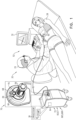
- Fig. 1 is a schematic illustration of an apparatus 20 being used for a cryogenic medical procedure, according to an embodiment of the present invention.
- the procedure assumed in the following description is on a breast tumor, but it will be understood that apparatus 20 may be used for other procedures, such as on a prostate or kidney tumor, and all such procedures are considered to be comprised within the scope of the present invention.
- probe 60 is non-disposable, as is assumed in the following description.
- probe 60 comprises a sterile disposable probe, and those having ordinary skill in the art will be able to adapt the following description, mutatis mutandis, for this type of probe.
- the physician may observe an image of the procedure on a screen 32.
- a proximal termination 56 of the probe is inserted into an opening 70 in a connector 68 of a cryogen storage unit 64.
- Storage unit 64 is operated by a processor 36, and, inter alia, comprises a cryogen pump 40 and a cryogen delivery section 66, both of which are under control of the processor.
- delivery section 66 comprises a cylindrical lumen 67, also herein termed a conduit 67, having a plurality of different diameters. Section 66 and conduit 67 are illustrated in Fig. 2B .
- a distal end of termination 56 is configured to mate with conduit 67, the distal end acting as a male section and the lumen as a female section. Once mated, the combination forms a cylindrical supply lumen 67S and a tubular return lumen 67R, and which may be used for delivery and return of cryogen. (Lumens 67S and 67R are illustrated in Fig. 3 .)
- cryogen 72 contained in the storage unit may be delivered via supply lumen 66S and the proximal end, through the probe, to the distal end.
- Cryogen returns from the distal end via the probe and the proximal end and return lumen 66R to the storage unit.
- proximal termination 56 is not removed from connector 68. Such removal, typically inadvertent, may cause cryogen to escape from lumens 66S and 66R and/or proximal termination 56. Such an escape is a safety hazard.
- a latch plate 76 in the connector automatically locks the proximal termination to the connector.
- unlocking of the proximal termination from the connector permitting removal of the proximal termination, may only be implemented positively, by simultaneous actuation of a button 80 and a latch plate retainer 84, the retainer being fixedly attached to the latch plate.
- FIGs. 2A and 2B are schematic drawings of connector 68, according to an embodiment of the present invention.
- the figures illustrate the connector in a number of different views, without proximal termination 56 being inserted into the connector.
- a callout "A” also illustrates two opposing faces 76A, 76B of latch plate 76, and a figure “B”illustrates a front view of the latch.
- connector 68 is assumed to be drawn on a set of xyz orthogonal axes.
- the z axis is assumed to be collinear with the axis of symmetry of lumen 67 and to have a positive direction that extends proximally and horizontally from section 66.
- Latch plate 76 is formed, in a disclosed embodiment, as a generally rectangular plate that is normal to the z axis, and that has edges that are assumed to be vertical and horizontal.
- the positive y axis is assumed to be parallel to a vertical edge of plate 76, directed up; the positive x axis is assumed to be parallel to a horizontal edge of plate, directed right when viewed distally along the z axis.
- An origin of the axes is assumed to reside in the plate. It will be appreciated that the orientations described herein are for clarity and by way of example, and that embodiments of the present invention may function in substantially any orientation.
- Latch plate 76 is held between a connector base plate 88, lying in an xy plane, and a connector cover 92.
- base plate 88 In base plate 88 are two shoulders, 96A 96B, both parallel to the y-axis and protruding from the plate in a positive z-direction, separated by the width of the latch plate, and the latch plate is positioned between the shoulders.
- the shoulders constrain the plate to move in a slot 98, between the shoulders, parallel to the y-axis. (Because it is attached to plate 76, plate retainer 84 also moves parallel to the y-axis.
- Latch plate 76 has two apertures formed within the plate: a generally slot-like aperture 100, parallel to the y-axis, and a generally oval aperture 104 which is penetrated by the z-axis. More details of the structure and the function of the apertures are given below.
- a cylindrical rod 108 (shown also in cross-section in the figure), which is formed as a plurality of solid cylinders 108A, 108B, 108C, of different diameters, penetrates slot-like aperture 100.
- Cylinder 108A has two circular grooves 108A1, 108A2 formed in the cylinder.
- Aperture 100 has two different slots 102, 106, each slot having a depth that is half the thickness of plate 76.
- Slot 102 has two different widths, an upper part 110 and a lower part 114 having a width corresponding to the diameter of cylinder 108C, and a central part 122 having a width corresponding to the diameter of cylinder 108B.
- Slot 106 is in four different sections, an upper section 126 and a lower section 130, both terminating in a semicircle and having a width corresponding to the diameter of cylinder 108C, an upper middle section 134 having the diameter of cylinder 108B, and a partially circular lower middle section 138, having a diameter equal to the diameter of cylinder 108A.
- There is an internal surface 142 in plate 76 formed by the different widths of the two slots.
- Button 80 connects to a proximal end of cylindrical rod 108.
- a distal end of the rod is held within a rod holder 112, which is fixed to base plate 88.
- the rod holder has a blind hole 116 having a diameter corresponding to the diameter of cylinder 108A of rod 108, and there is a spring 118 within the blind hole contacting the rod distal end, the spring pushing the rod in a positive z-direction. It will be appreciated that rod 108 is able to slide in hole 116 in a z-direction.
- Rod holder 112 acts as a support for two printed circuit (PC) boards PC1, PC2.
- Board PC1 has two pairs of radiation transmitters TX1A, TX1B, and TX2A, TX2B, herein by way of example assumed to comprise infra-red emitters.
- Board PC2 has two pairs of receivers RX1A, RX1B, and RX2A, RX2B configured to receive the radiation transmitted by the transmitters.
- the receivers are assumed to comprise phototransistors.
- channels C1A, C1B, C2A, C2B there are four channels C1A, C1B, C2A, C2B, in holder 112, and transmitters TX1A, TX1B, TX2A, TX2B are aligned respectively with channels C1A, C1B, C2A, C2B and with receivers RX1A, RX1B, and RX2A, RX2B.
- transmitters TX1A, TX1B, TX2A, TX2B are aligned respectively with channels C1A, C1B, C2A, C2B and with receivers RX1A, RX1B, and RX2A, RX2B.
- cylinder 108A does obstruct the channels, except when grooves 108A1 or 108A2 align with a channel.
- receivers RX1A, RX1B, RX2A, RX2B act as sensors, and are also termed herein sensors RX1A, RX1B, RX2A, RX2B.
- Sensors RX1A, RX1B, RX2A, RX2B detect, inter alia, the position of latch plate 76 in slot 98.
- latch plate 76 is constrained to move in a y-direction, in slot 98, by shoulders 96A, 96B.
- the plate is pushed in a positive y-direction by springs 120, which are held between plate retainer 84 and cover 92.
- the plate In the state illustrated in Figs. 2A and 2B , i.e., where proximal termination 56 is not in the connector, the plate is prevented from moving in a y-direction by a semicircular section 124 of aperture 104 contacting a circular split lip 128 protruding in a z-direction from a latch backing disc 132.
- Disc 132 and split lip 128 are maintained in contact with plate 76 by springs 136, which push the disc in a positive z direction, and which permit the disc to move along the z axis.
- latch plate 76 is in its lowest possible y-position.
- an upper semicircular section 140 of section 126 mates with cylinder 108C of rod 108.
- shoulder 144 between cylinder 108B and cylinder 108C is pushed against face 76B of plate 76. Consequently, rod 108 is fixed in a position where it is unable to move parallel to the z-axis.
- neither groove 108A1 nor groove 108A2 align with any of channels C1A, C1B, C2A, C2B. Rather, the channels are obstructed by cylinder 108A, so that none of sensors RX1A, RX1B, RX2A, RX2B, activate.
- plate 76 and rod 108 are in other positions, but in the situation illustrated in Figs. 2A and 2B , where there is nothing inserted in aperture 104, latch plate 76 is in its lowest possible y-position, and rod 108 is in its most distal position measured parallel to the z axis.
- Fig. 3 is a schematic drawing of connector 68 when proximal termination 56 of probe 60 is inserted into the connector, according to an embodiment of the present invention.
- the figure illustrates the connector and the termination in a perspective view, substantially as shown in Fig. 1 and in a cross-section view.
- the figure also illustrates the connector in a perspective view.
- Termination 56 fits within conduit 67, forming cylindrical supply lumen 67S and connecting to tubular return lumen 67R. Termination 56 has an axis of symmetry that, when it is in the conduit 67, is collinear with the z-axis. On insertion of termination 56 into opening 70, the termination pushes lip 128 and its latch backing disc 132 in a negative z-direction against springs 136, so that the lip disengages from semicircular opening 124. The disengagement permits latch plate 76 to move in a y-direction, and springs 120 push the plate in a positive y-direction.
- Latch plate 76 moves in a positive y-direction until opening 124 engages with a circular groove 150 in termination 56. The engagement grips the termination, and locks it in place so that the termination may not be removed from opening 70, except as described below.
- Groove 150 has a radius R 1 , and it will be appreciated that it is the value of R 1 that determines the location of latch plate 76 when termination 56 is in place, and so determines the distance moved by the latch plate when the termination is inserted into opening 70.
- latch plate 76 causes shoulder 144 of rod 108 to slide in slot-like aperture 100 against face 76B of the latch plate. While shoulder 144 slides against face 76B, the sliding continues until the slot that rod 108 is in enlarges, at section 134 ( Fig. 2A ); at this point spring 118 pushes rod 108 in a positive z-direction until shoulder 144 contacts internal surface 142.
- the positive z-direction movement of rod 108 causes groove 108A2 to align with channels C2A and C2B, so that the channels are not obstructed. (Channels C1A and C1B are obstructed by cylinder 108A.) Consequently transmitters TX2A and TX2B activate respective sensors RX2A and RX2B.
- the sensor activation acts as a positive indication that termination 56 has been inserted into opening 70.
- the positive indication from the sensors may be used by delivery section 66 to recognize that it is safe to permit flow of cryogen from storage unit 64, and thus to activate the delivery section. As is described further below, deactivation of the sensors prevents cryogen flow.
- the termination To remove termination 56 from opening 70, the termination must be disengaged from latch plate 76.
- the disengagement requires the latch plate to move down, so that circular groove 150 is no longer gripped by the latch plate, but in the state illustrated in Fig. 3 this is not possible, since cylinder 108B contacts an upper part of upper middle section 134.
- Embodiments of the invention provide a two step method for removal of termination 56.
- a first step button 80 is pushed in, typically by one finger or a thumb of physician 24, so that cylinder 108B no longer contacts an upper part of upper middle section 134.
- Springs 120 still maintain the latch plate gripping groove 150, but the removal of contact between cylinder 108B and section 134, permits a second step.
- the physician uses a second of his/her digits to press down on plate retainer 84, so that latch plate 76 moves in a negative y-direction, and disengages from groove 150 of the termination. The physician may then remove the termination.
- the first step, of pushing button 80 in deactivates sensors RX2A and RX2B, by blocking the channels to the sensors.
- the sensor deactivation may be used to deactivate cryogen delivery section 66 of cryogen unit 64 and operation by processor 36 of pump 40, so preventing cryogen flow from the section and from the unit.
- inadvertent pushing of button 80 and pressing retainer 84 deactivates sensors RX2A and RX2B, and thus halts cryogen flow by deactivating delivery section 66 and pump 40.
- Fig. 4 is a schematic drawing of connector 68 when a sealing plug 200 is inserted into the connector, according to an embodiment of the present invention.
- the figure illustrates the connector and the plug in a perspective view, substantially as shown in Fig. 1 and in a cross-section view.
- the figure also illustrates the connector in a perspective view.
- cryogen unit 64 When probe 60 is not in use, cryogen unit 64 may be sealed by plug 200, in order to prevent air and/or moisture entering the unit, as well as to reduce the evaporation of any cryogen in the unit, and to prevent any uncontrolled release of cryogen.
- Plug 200 fits within lumen 67, being held in the lumen by an O-ring 204, and the plug has an axis of symmetry that, when it is in the lumen, is collinear with the z-axis.
- the plug pushes lip 128 and its latch backing disc 132 in a negative z-direction against springs 136, so that the lip disengages from semicircular opening 124.
- the disengagement permits latch plate 76 to move in a y-direction, and springs 120 push the plate in a positive y-direction.
- Latch plate 76 moves in a positive y-direction until opening 124 engages with a circular groove 208 in plug 200. The engagement grips the plug, and locks it in place so that the plug may not be removed from opening 70, except as described below.
- Groove 208 has a radius R 2 , and it will be appreciated that it is the value of R 2 that determines the location of latch plate 76 when plug 200 is in place, and so determines the distance moved by the latch plate when the plug is inserted into opening 70.
- R 1 and R 2 are configured to be different, and in the disclosed embodiment, R 2 ⁇ R 1 .
- processor 36 checks, using sensors RX1A and RX1B that plug 200 is in place, so that, after removal of the plug, termination 56 of probe 60 may be inserted into the connector. In addition, on shutting down, processor 36 may check, using the sensors, that plug 200 is in place, so as to enable an orderly shutdown.
- embodiments of the invention provide a two step method for removal of plug 200.
- a first step button 80 is pushed in, as for termination 56, typically by physician 24 using one of his/her digits.
- the physician uses a second digit to press down on plate retainer 84, so that latch plate 76 moves in a negative y-direction, and disengages from groove 208 of the plug. The physician may then remove the plug.
- the first step, of pushing button 80 in deactivates sensors RX1A and RX1B, by blocking the channels to the receivers.
Landscapes
- Engineering & Computer Science (AREA)
- Health & Medical Sciences (AREA)
- General Engineering & Computer Science (AREA)
- Surgery (AREA)
- Life Sciences & Earth Sciences (AREA)
- Nuclear Medicine, Radiotherapy & Molecular Imaging (AREA)
- Mechanical Engineering (AREA)
- Biomedical Technology (AREA)
- Otolaryngology (AREA)
- Heart & Thoracic Surgery (AREA)
- Medical Informatics (AREA)
- Molecular Biology (AREA)
- Animal Behavior & Ethology (AREA)
- General Health & Medical Sciences (AREA)
- Public Health (AREA)
- Veterinary Medicine (AREA)
- Surgical Instruments (AREA)
- Quick-Acting Or Multi-Walled Pipe Joints (AREA)
- Details Of Connecting Devices For Male And Female Coupling (AREA)
Description
- This invention relates generally to cryogenics, and specifically to connecting entities used in a cryogenic system together.
- Entities used in a cryogenic system, such as a Dewar or a medical probe, are typically well-insulated to reduce evaporation of cryogen, and are also typically well-sealed to prevent ingress of elements such as moisture. In order to connect the entities, any connector should provide the same properties of good insulation and sealing, while permitting connection and disconnection of the entities.
-
US3,845,974 describes a coupling device for a line conduit conveying cryogenic liquids. The device is stated to be of the easy make-and-break type and to comprise two connectable coupling bodies.US3,988,029 describes a coupling device for cryogenic fluids which allows passage of liquid and vapor simultaneously through one coaxially arranged assembly. The device is stated to have low heat transfer insulation integral with the coupling and also the ability to connect and disconnect without use of tools.US4,107,946 describes an interface for a magnet Dewar which includes a low leakage disconnect fitting that retains the vacuum integrity of both the Dewar and a connected transfer line. -
US5,363,879 describes a coupling assembly for dispensing cryogenic fluids. The assembly has an upstream terminus coupled to a source of cryogenic fluid and a downstream terminus connected to a container for receiving the cryogenic fluid. A poppet valve assembly is disposed at the upstream dispensing terminus. -
US5,429,155 describes a cryogenic fluid coupling that has a male half and a female half. Each half has a poppet valve arranged to move toward and way from a seat. The male half has an outer sleeve which is adapted to guide initial joinder of the female half distal end. -
US5,452,582 describes a cryo-probe wherein refrigerant is furnished from a high pressure, room temperature supply. Refrigerant flows through a pre-cooling heat exchanger in the probe and through a restrictor wherein the pressure drops. A concentric gas coupling may be used at a warm end of the probe, whereby a nut that threadably engages external threads on a body, rigidly connects the body to a core and a nipple. -
US5,946,920 describes controlling the flow rate of a liquid cryogen by controlling variably the pressure propellant gas acting directly or indirectly on the liquid cryogen. -
US5,957,918 describes a cryosurgical instrument having a Dewar and a cap which is threaded onto the Dewar when in use, with a main valve portion secured to the cap by threads. The handedness of the threads on the main valve portion are opposite to the handedness of the cap threads.US6,035,646 describes a liquid cryogen withdrawal device that includes a plug for insertion into the neck of a cryogen-containing Dewar in a gas-tight relationship.US6,082,400 describes a coupling for connecting vacuum-insulated line ends via a coupling socket and a coupling plug. The socket and the plug are provided for conveying a cryogenic medium and have closing elements. -
US6,145,322 describes a cryogenic coupler that includes a socket and a plug that can be detachably inserted into the socket. The socket and the plug have passages for passing a cryogenic medium therethrough, and are provided with valves for blocking the respective passages when the plug is disconnected from the socket. -
US6,183,019 describes a coupling device that can connect two cryogenic fluid conduits in fluid communication without creating a temperature change. The coupling device is stated to have a fluid flow path with a substantially constant cross-sectional area. The coupling device is stated to be designed to be easy to connect and disconnect and to provide a secure connection, in particular at a low temperature. -
US6,945,477 describes a cryogenic coupling device that includes a valved receptacle and a valved nozzle. Rollers in an outer collar of the receptacle are received in helical channels along a collar of the nozzle. A notch or detent in each of the channels provides a vent position to vent fluid before the nozzle is fully disconnected from the receptacle. -
US7,128,347 describes a quick connector coupling for forming a joint in a fluid line system. The quick connector coupling has a female connector body, a male member and a latch coupled to the connector body. -
US7,189,228 describes a disposable probe assembly that includes a breakaway collar. The collar, when twisted away, activates a finger lock element. -
US7,381,207 describes a quick disconnect assembly that includes a reusable assembly including a distal end having a male lip. There is a disposable assembly having quick disconnect capabilities when utilized with the reusable assembly. -
US7,469,718 describes a cylindrical quick disconnect female cryogenic coupler, interconnected with a cryogenic fluid transfer apparatus. The coupler includes a coupler body with a first cavity housing a laterally severed tubular bushing, and an adaptor having one end attached to the coupler body and another end to the apparatus.US8,092,448 describes a liquid cryogen fluid system for providing cryogenic liquid to a cryoprobe. Flow of cryogen from a cryogen source to the cryoprobe is induced by pressurizing the cryogen source with air delivered by a pressurization pump.US8,517,749 describes an apparatus that enables quick disconnect termination or connection for cryogenic transfer lines. The apparatus is a connector that will allow two lines to be connected and coupled to simultaneously allow fluid flow to occur and electrical communication to ensue. The connection and termination are stated to occur successfully under a pressurized environment. -
US8,784,409 describes a cryogenic medical device for delivery of subcooled liquid cryogen to various configurations of cryoprobes. The device is a closed or semi-closed system in which the liquid cryogen is contained in both the supply and return stages. -
US10,022,175 -
US10,054,262 -
US10,159,522 -
US10,531,656 US10,859,211 US2004/0024392 describes apparatus for delivery of cryosurgery fluid in a surgical or other medical environment. The apparatus comprises a multiple-layered expanded polytetrafluoroethylene conduit that has a low profile, has low thermal conductivity, and is stated to provide exceptional flexibility. -
US2019/0390822 describes a supply line that supplies cryogenic liquid to a plurality of cryogenic freezers. A fill line having a diameter greater than the supply line allows a storage tank to be filled at a greater speed relative to filling through the supply line and allows the storage tank to be filled while supplying cryogenic liquid to the cryogenic freezers. -
CN203641719U describes a connector connecting a gas storage tank and a Dewar. The connector has a threaded sleeve piece used for connecting with a fluid outlet of the gas storage tank. There is a corresponding connector body used for filling of the Dewar. -
GB2321531A -
US2021396336 discloses a connection unit for connecting fluid lines, wherein the connection unit comprises a first connection body and a second connection body, wherein the connection unit comprises a machine-readable code which is not detectable when the first connection body and the second connection body are in an unconnected state and which is detectable when the first connection body and the second connection body are in a connected state. -
US9157560 - According to an aspect of the present invention, there is provided a cryogenic apparatus as set out in the first of the appending independent claims. There is also provided, in accordance with another aspect of the present invention, a method as set out in the second of the appending independent claims. Features of various embodiments are set out in the appending dependent claims.
- There is disclosed herein a cryogenic apparatus, comprising: a cryogenic probe; a connector having a connector base plate configured for connection to a conduit carrying a cryogen and a slot extending across the base plate; a plug, which is configured for insertion into an opening in the base plate; a latch plate configured to slide within the slot between a first position, in which the plug is configured for being inserted through an aperture in the latch plate into the opening, and a second position, in which the cryogenic probe is configured for being inserted through the aperture and being brought into fluid communication with the opening; and a sensor, which is coupled to control a flow of the cryogen through the conduit by detecting whether the latch plate is in the first position or the second position.
- In examples, the plug has a groove, and the aperture grips the groove, when the plug is inserted through the aperture, so as to lock the plug to the latch plate. In examples, the cryogenic probe has a groove, and the aperture grips the groove, when the probe is inserted through the aperture, so as to lock the probe to the latch plate. In examples, there is a control rod which penetrates a further aperture in the latch plate and which is configured to operate the sensor. In examples, there is a control rod which penetrates a further aperture in the latch plate and which, when the latch plate is in the first position, is in a first control rod position that deactivates the sensor so as to prevent flow of the cryogen, and when the latch plate is in the second position, is in a second control rod position that activates the sensor so as to permit flow of the cryogen. In examples, there is a control rod which penetrates a further aperture in the latch plate and which, when the latch plate is in the first position, is in a first control rod position that prevents the latch plate from moving from the first position, and when the latch plate is in the second position, is in a second control rod position that prevents the latch plate from moving from the second position. Preferably, the control rod, when translated from the first control rod position permits the latch plate moving from the first position, and, when translated from the second control rod position permits the latch plate moving from the second position.
- There is also disclosed herein a method, comprising: providing a cryogenic apparatus comprising: a cryogenic probe; a connector having a connector base plate configured for connection to a conduit carrying a cryogen and a slot extending across the base plate; a plug configured for insertion into an opening in the base plate; a latch plate; and a sensor; sliding the latch plate within the slot between a first position, in which the plug is configured for being inserted through an aperture in the latch plate into the opening, and a second position, in which the cryogenic probe is configured for being inserted through the aperture and being brought into fluid communication with the opening; and coupling the sensor to control a flow of the cryogen through the conduit by detecting whether the latch plate is in the first position or the second position.
- The present disclosure will be more fully understood from the following detailed description of the embodiments thereof, taken together with the drawings, in which:
-
Fig. 1 is a schematic illustration of an apparatus being used for a cryogenic medical procedure; -
Figs. 2A and2B are schematic drawings of a connector of the apparatus; -
Fig. 3 is a schematic drawing of the connector when a proximal termination of a probe is inserted into the connector; and -
Fig. 4 is a schematic drawing of the connector when a sealing plug is inserted into the connector. - In a medical cryogenic procedure, it is important, from a safety point of view, to maintain the cryogen isolated and sealed from the surgeon performing the procedure, and from the patient undergoing the procedure, so that neither have any direct exposure to the cryogen. The procedure typically involves connecting and disconnecting a probe, which in some embodiments may be a sterile disposable probe, used for the procedure from a Dewar storing the cryogen, and at both times there may be leakage of the cryogen. In addition, when the probe is disconnected from the Dewar, it is important to seal the connection to the Dewar to reduce evaporation of the cryogen, to prevent ice forming on the connection, and to prevent expulsion of the cryogen from the Dewar. While speed and simplicity of operation is important for connecting and disconnecting the probe, as well as for sealing the connection, it is equally important, if not more so, that these actions cannot occur inadvertently.
- Embodiments of the invention address these considerations by providing a connector to a Dewar storage unit that has a pump for the stored cryogen. The connector, together with a latch incorporated in the connector, has three states: a sealed state, which has a sealing plug in the connector, an active state, when the probe is in the connector, and an intermediate state when neither the sealing plug nor the probe are in the connector. Change from the intermediate state to either the sealed state or the active state, by respective insertion of the sealing plug or the probe into the connector, is fast and simple, and may be accomplished with only one hand. Once inserted, the latch locks the probe or the plug in place, so that inadvertent removal is not possible.
- In addition, for safety, there is an activation mechanism attached to the latch so that removal of the plug or the probe requires initially operating the mechanism with two fingers of one hand, so as to free the plug or probe. Once freed, the other hand may extract the plug or probe. Also for safety, the mechanism is configured to detect the presence of the plug and the probe when they are inserted into the connector, by activating respective sensors indicating the presence of the plug or of the probe. Detection of the presence of the plug renders the Dewar pump inoperative, but when the presence of the probe is detected, the pump may be operated.
- In the following description, like elements in the drawings are identified by like numerals. In addition, all directional references (e.g., upper, lower, upward, downward, left, right, top, bottom, above, below, vertical, and horizontal) are only used for identification purposes to aid the reader's understanding of the present invention, and do not create limitations, particularly as to the position, orientation, or use of embodiments of the invention.
- Reference is now made to
Fig. 1 , which is a schematic illustration of anapparatus 20 being used for a cryogenic medical procedure, according to an embodiment of the present invention. By way of example the procedure assumed in the following description is on a breast tumor, but it will be understood thatapparatus 20 may be used for other procedures, such as on a prostate or kidney tumor, and all such procedures are considered to be comprised within the scope of the present invention. - The procedure is performed by a
physician 24 on apatient 28, and the physician has inserted adistal end 52 of a probe 60 into the patient. Typically, probe 60 is non-disposable, as is assumed in the following description. In some embodiments probe 60 comprises a sterile disposable probe, and those having ordinary skill in the art will be able to adapt the following description, mutatis mutandis, for this type of probe. The physician may observe an image of the procedure on ascreen 32. - A
proximal termination 56 of the probe is inserted into anopening 70 in aconnector 68 of acryogen storage unit 64.Storage unit 64 is operated by aprocessor 36, and, inter alia, comprises a cryogen pump 40 and acryogen delivery section 66, both of which are under control of the processor. In oneembodiment delivery section 66 comprises acylindrical lumen 67, also herein termed aconduit 67, having a plurality of different diameters.Section 66 andconduit 67 are illustrated inFig. 2B . - A distal end of
termination 56 is configured to mate withconduit 67, the distal end acting as a male section and the lumen as a female section. Once mated, the combination forms acylindrical supply lumen 67S and atubular return lumen 67R, and which may be used for delivery and return of cryogen. (Lumens Fig. 3 .) Thus,cryogen 72 contained in the storage unit may be delivered viasupply lumen 66S and the proximal end, through the probe, to the distal end. Cryogen returns from the distal end via the probe and the proximal end and returnlumen 66R to the storage unit. - During the procedure it is important that
proximal termination 56 is not removed fromconnector 68. Such removal, typically inadvertent, may cause cryogen to escape fromlumens proximal termination 56. Such an escape is a safety hazard. To prevent inadvertent removal, once the proximal termination has been inserted into the connector and mated with the lumens, alatch plate 76 in the connector automatically locks the proximal termination to the connector. As a further safety aspect, unlocking of the proximal termination from the connector, permitting removal of the proximal termination, may only be implemented positively, by simultaneous actuation of abutton 80 and alatch plate retainer 84, the retainer being fixedly attached to the latch plate. The construction and operation of the latch plate inconnector 68 is described in more detail with respect toFigs. 2A ,2B , below. -
Figs. 2A and2B are schematic drawings ofconnector 68, according to an embodiment of the present invention. The figures illustrate the connector in a number of different views, withoutproximal termination 56 being inserted into the connector. A callout "A" also illustrates two opposingfaces latch plate 76, and a figure "B"illustrates a front view of the latch. - For clarity in the description herein,
connector 68 is assumed to be drawn on a set of xyz orthogonal axes. In a disclosed embodiment, the z axis is assumed to be collinear with the axis of symmetry oflumen 67 and to have a positive direction that extends proximally and horizontally fromsection 66.Latch plate 76 is formed, in a disclosed embodiment, as a generally rectangular plate that is normal to the z axis, and that has edges that are assumed to be vertical and horizontal. The positive y axis is assumed to be parallel to a vertical edge ofplate 76, directed up; the positive x axis is assumed to be parallel to a horizontal edge of plate, directed right when viewed distally along the z axis. An origin of the axes is assumed to reside in the plate. It will be appreciated that the orientations described herein are for clarity and by way of example, and that embodiments of the present invention may function in substantially any orientation. -
Latch plate 76 is held between aconnector base plate 88, lying in an xy plane, and aconnector cover 92. Inbase plate 88 are two shoulders,96A 96B, both parallel to the y-axis and protruding from the plate in a positive z-direction, separated by the width of the latch plate, and the latch plate is positioned between the shoulders. The shoulders constrain the plate to move in aslot 98, between the shoulders, parallel to the y-axis. (Because it is attached to plate 76,plate retainer 84 also moves parallel to the y-axis. -
Latch plate 76 has two apertures formed within the plate: a generally slot-like aperture 100, parallel to the y-axis, and a generallyoval aperture 104 which is penetrated by the z-axis. More details of the structure and the function of the apertures are given below. - A cylindrical rod 108 (shown also in cross-section in the figure), which is formed as a plurality of
solid cylinders like aperture 100.Cylinder 108A has two circular grooves 108A1, 108A2 formed in the cylinder. There is ashoulder 146 betweencylinder 108A andcylinder 108B, and ashoulder 144 betweencylinders -
Aperture 100 has twodifferent slots plate 76.Slot 102 has two different widths, anupper part 110 and alower part 114 having a width corresponding to the diameter ofcylinder 108C, and acentral part 122 having a width corresponding to the diameter ofcylinder 108B.Slot 106 is in four different sections, anupper section 126 and alower section 130, both terminating in a semicircle and having a width corresponding to the diameter ofcylinder 108C, an uppermiddle section 134 having the diameter ofcylinder 108B, and a partially circular lowermiddle section 138, having a diameter equal to the diameter ofcylinder 108A. There is aninternal surface 142 inplate 76, formed by the different widths of the two slots. -
Button 80 connects to a proximal end ofcylindrical rod 108. A distal end of the rod is held within arod holder 112, which is fixed tobase plate 88. The rod holder has ablind hole 116 having a diameter corresponding to the diameter ofcylinder 108A ofrod 108, and there is aspring 118 within the blind hole contacting the rod distal end, the spring pushing the rod in a positive z-direction. It will be appreciated thatrod 108 is able to slide inhole 116 in a z-direction. -
Rod holder 112 acts as a support for two printed circuit (PC) boards PC1, PC2. Board PC1 has two pairs of radiation transmitters TX1A, TX1B, and TX2A, TX2B, herein by way of example assumed to comprise infra-red emitters. Board PC2 has two pairs of receivers RX1A, RX1B, and RX2A, RX2B configured to receive the radiation transmitted by the transmitters. Herein by way of example the receivers are assumed to comprise phototransistors. There are four channels C1A, C1B, C2A, C2B, inholder 112, and transmitters TX1A, TX1B, TX2A, TX2B are aligned respectively with channels C1A, C1B, C2A, C2B and with receivers RX1A, RX1B, and RX2A, RX2B. Thus, absent any obstruction in the channels, radiation from the transmitters is received by, and activates the receivers. - As is described below,
cylinder 108A does obstruct the channels, except when grooves 108A1 or 108A2 align with a channel. - As is explained further below, receivers RX1A, RX1B, RX2A, RX2B, act as sensors, and are also termed herein sensors RX1A, RX1B, RX2A, RX2B. Sensors RX1A, RX1B, RX2A, RX2B detect, inter alia, the position of
latch plate 76 inslot 98. - As stated above,
latch plate 76 is constrained to move in a y-direction, inslot 98, byshoulders springs 120, which are held betweenplate retainer 84 andcover 92. In the state illustrated inFigs. 2A and2B , i.e., whereproximal termination 56 is not in the connector, the plate is prevented from moving in a y-direction by asemicircular section 124 ofaperture 104 contacting acircular split lip 128 protruding in a z-direction from alatch backing disc 132.Disc 132 and splitlip 128 are maintained in contact withplate 76 bysprings 136, which push the disc in a positive z direction, and which permit the disc to move along the z axis. - In the situation illustrated in
Figs. 2A and2B ,latch plate 76 is in its lowest possible y-position. In the illustrated situation an uppersemicircular section 140 ofsection 126 mates withcylinder 108C ofrod 108. In addition, by virtue of the force exerted in the positive z direction byspring 118 onrod 108,shoulder 144 betweencylinder 108B andcylinder 108C is pushed againstface 76B ofplate 76. Consequently,rod 108 is fixed in a position where it is unable to move parallel to the z-axis. In this position, neither groove 108A1 nor groove 108A2 align with any of channels C1A, C1B, C2A, C2B. Rather, the channels are obstructed bycylinder 108A, so that none of sensors RX1A, RX1B, RX2A, RX2B, activate. - As is described below, in embodiments of the invention,
plate 76 androd 108 are in other positions, but in the situation illustrated inFigs. 2A and2B , where there is nothing inserted inaperture 104,latch plate 76 is in its lowest possible y-position, androd 108 is in its most distal position measured parallel to the z axis. -
Fig. 3 is a schematic drawing ofconnector 68 whenproximal termination 56 of probe 60 is inserted into the connector, according to an embodiment of the present invention. The figure illustrates the connector and the termination in a perspective view, substantially as shown inFig. 1 and in a cross-section view. The figure also illustrates the connector in a perspective view. -
Termination 56 fits withinconduit 67, formingcylindrical supply lumen 67S and connecting totubular return lumen 67R.Termination 56 has an axis of symmetry that, when it is in theconduit 67, is collinear with the z-axis. On insertion oftermination 56 intoopening 70, the termination pusheslip 128 and itslatch backing disc 132 in a negative z-direction againstsprings 136, so that the lip disengages fromsemicircular opening 124. The disengagement permits latchplate 76 to move in a y-direction, and springs 120 push the plate in a positive y-direction. -
Latch plate 76 moves in a positive y-direction until opening 124 engages with acircular groove 150 intermination 56. The engagement grips the termination, and locks it in place so that the termination may not be removed from opening 70, except as described below.Groove 150 has a radius R1, and it will be appreciated that it is the value of R1 that determines the location oflatch plate 76 whentermination 56 is in place, and so determines the distance moved by the latch plate when the termination is inserted intoopening 70. - The vertical movement of
latch plate 76 causesshoulder 144 ofrod 108 to slide in slot-like aperture 100 againstface 76B of the latch plate. Whileshoulder 144 slides againstface 76B, the sliding continues until the slot thatrod 108 is in enlarges, at section 134 (Fig. 2A ); at thispoint spring 118 pushesrod 108 in a positive z-direction untilshoulder 144 contactsinternal surface 142. - The positive z-direction movement of
rod 108 causes groove 108A2 to align with channels C2A and C2B, so that the channels are not obstructed. (Channels C1A and C1B are obstructed bycylinder 108A.) Consequently transmitters TX2A and TX2B activate respective sensors RX2A and RX2B. The sensor activation acts as a positive indication thattermination 56 has been inserted intoopening 70. The positive indication from the sensors may be used bydelivery section 66 to recognize that it is safe to permit flow of cryogen fromstorage unit 64, and thus to activate the delivery section. As is described further below, deactivation of the sensors prevents cryogen flow. - To remove
termination 56 from opening 70, the termination must be disengaged fromlatch plate 76. The disengagement requires the latch plate to move down, so thatcircular groove 150 is no longer gripped by the latch plate, but in the state illustrated inFig. 3 this is not possible, sincecylinder 108B contacts an upper part of uppermiddle section 134. - Embodiments of the invention provide a two step method for removal of
termination 56. As afirst step button 80 is pushed in, typically by one finger or a thumb ofphysician 24, so thatcylinder 108B no longer contacts an upper part of uppermiddle section 134.Springs 120 still maintain the latchplate gripping groove 150, but the removal of contact betweencylinder 108B andsection 134, permits a second step. - In the second step, the physician uses a second of his/her digits to press down on
plate retainer 84, so thatlatch plate 76 moves in a negative y-direction, and disengages fromgroove 150 of the termination. The physician may then remove the termination. - It will be understood that the first step, of pushing
button 80 in, deactivates sensors RX2A and RX2B, by blocking the channels to the sensors. The sensor deactivation may be used to deactivatecryogen delivery section 66 ofcryogen unit 64 and operation byprocessor 36 of pump 40, so preventing cryogen flow from the section and from the unit. It will also be understood that inadvertent pushing ofbutton 80 andpressing retainer 84 deactivates sensors RX2A and RX2B, and thus halts cryogen flow by deactivatingdelivery section 66 and pump 40. -
Fig. 4 is a schematic drawing ofconnector 68 when a sealingplug 200 is inserted into the connector, according to an embodiment of the present invention. The figure illustrates the connector and the plug in a perspective view, substantially as shown inFig. 1 and in a cross-section view. The figure also illustrates the connector in a perspective view. - When probe 60 is not in use,
cryogen unit 64 may be sealed byplug 200, in order to prevent air and/or moisture entering the unit, as well as to reduce the evaporation of any cryogen in the unit, and to prevent any uncontrolled release of cryogen. - Plug 200 fits within
lumen 67, being held in the lumen by an O-ring 204, and the plug has an axis of symmetry that, when it is in the lumen, is collinear with the z-axis. On insertion ofplug 200 intoopening 70, the plug pusheslip 128 and itslatch backing disc 132 in a negative z-direction againstsprings 136, so that the lip disengages fromsemicircular opening 124. The disengagement permits latchplate 76 to move in a y-direction, and springs 120 push the plate in a positive y-direction. -
Latch plate 76 moves in a positive y-direction until opening 124 engages with acircular groove 208 inplug 200. The engagement grips the plug, and locks it in place so that the plug may not be removed from opening 70, except as described below.Groove 208 has a radius R2, and it will be appreciated that it is the value of R2 that determines the location oflatch plate 76 whenplug 200 is in place, and so determines the distance moved by the latch plate when the plug is inserted intoopening 70. In embodiments of the invention, R1 and R2 are configured to be different, and in the disclosed embodiment, R2 < R1. - For the case when R2 < R1,
shoulder 144 initially slides as described above for termination 56 (Fig. 3 ). Because R2 < R1, the possible vertical motion of the latch plate is larger than is the case with the termination. Consequently latchplate 76 continues moving vertically upwards untilrod 108 is able to entercentral part 122 of slot 102 (Fig. 2A ). When it enters the central section,spring 118 pushes the rod in a positive z-direction untilshoulder 146 contacts face 76B of the latch plate. In thiscase cylinder 108B contacts an upper part ofcentral section 122, and this contact prevents the latch plate from moving down. - The positive z-direction movement of
rod 108 causes groove 108A1 to align with channels C1A and C1B, so that the channels are not obstructed. (Channels C2A and C2B are now obstructed bycylinder 108A.) Consequently transmitters TX1A and TX1B activate respective sensors RX1A and RX1B. The sensor activation acts as a positive indication that plug 200 has been inserted intoopening 70. - Typically, when
apparatus 20 is powered on,processor 36 checks, using sensors RX1A and RX1B that plug 200 is in place, so that, after removal of the plug,termination 56 of probe 60 may be inserted into the connector. In addition, on shutting down,processor 36 may check, using the sensors, that plug 200 is in place, so as to enable an orderly shutdown. - As for
termination 56, embodiments of the invention provide a two step method for removal ofplug 200. As afirst step button 80 is pushed in, as fortermination 56, typically byphysician 24 using one of his/her digits. In the second step, which is now permitted since the first step enables the latch plate to be moved vertically, the physician uses a second digit to press down onplate retainer 84, so thatlatch plate 76 moves in a negative y-direction, and disengages fromgroove 208 of the plug. The physician may then remove the plug. - It will be understood that the first step, of pushing
button 80 in, deactivates sensors RX1A and RX1B, by blocking the channels to the receivers. - It will be appreciated that the embodiments described above are cited by way of example, and that combinations and subcombinations of the various features described hereinabove, as well as variations and modifications thereof which would occur to persons skilled in the art upon reading the foregoing description and which are not disclosed in the prior art may be made within the scope of the appending claims.
Claims (12)
- A cryogenic apparatus, comprising:a cryogenic probe (60);a connector (68) comprising:a connector base plate (88) configured for connection to a conduit (67) carrying a cryogen, anda slot (98) extending across the base plate;a plug (200), which is configured for insertion into an opening (70) in the base plate;a latch plate (76) configured to slide within the slot between a first position, in which the plug is configured for being inserted through an aperture (104) in the latch plate into the opening, and a second position, in which the cryogenic probe is configured for being inserted through the aperture and being brought into fluid communication with the opening; anda sensor (RX1A, RX1B, RX2A, RX2B), which is coupled to control a flow of the cryogen through the conduit by detecting whether the latch plate is in the first position or the second position.
- The cryogenic apparatus according to claim 1, and comprising a control rod (108) which penetrates a further aperture (100) in the latch plate and which is configured to operate the sensor.
- The cryogenic apparatus according to claim 1, and comprising a control rod which penetrates a further aperture in the latch plate and which, when the latch plate is in the first position, is in a first control rod position that deactivates the sensor so as to prevent flow of the cryogen, and when the latch plate is in the second position, is in a second control rod position that activates the sensor so as to permit flow of the cryogen.
- The cryogenic apparatus according to claim 1, and comprising a control rod which penetrates a further aperture in the latch plate and which, when the latch plate is in the first position, is in a first control rod position that prevents the latch plate from moving from the first position, and when the latch plate is in the second position, is in a second control rod position that prevents the latch plate from moving from the second position.
- The cryogenic apparatus according to claim 4, wherein the control rod, when translated from the first control rod position permits the latch plate moving from the first position, and, when translated from the second control rod position permits the latch plate moving from the second position.
- A method, comprising:
providing a cryogenic apparatus, comprising:a cryogenic probe (60);a connector (68) comprising:a connector base plate (88) configured for connection to a conduit (67) carrying a cryogen, anda slot (98) extending across the base plate;a plug (200) configured for insertion into an opening (70) in the base plate;a latch plate (76); anda sensor (RX1A, RX1B, RX2A, RX2B);sliding the latch plate (76) within the slot between a first position, in which the plug is configured for being inserted through an aperture (104) in the latch plate into the opening, and a second position, in which the cryogenic probe (60) is configured for being inserted through the aperture and being brought into fluid communication with the opening; andcoupling the sensor (RX1A, RX1B, RX2A, RX2B) to control a flow of the cryogen through the conduit by detecting whether the latch plate is in the first position or the second position. - The method according to claim 6, wherein the plug comprises a groove (208), and wherein the aperture grips the groove, when the plug is inserted through the aperture, so as to lock the plug to the latch plate.
- The method according to claim 6, wherein the cryogenic probe comprises a groove, and wherein the aperture grips the groove, when the probe is inserted through the aperture, so as to lock the probe to the latch plate.
- The method according to any of claims 6-8, and comprising providing a control rod (108) which penetrates a further aperture (100) in the latch plate and which is configured to operate the sensor.
- The method according to any of claims 6-8, and comprising providing a control rod which penetrates a further aperture in the latch plate and which, when the latch plate is in the first position, is in a first control rod position that deactivates the sensor so as to prevent flow of the cryogen, and when the latch plate is in the second position, is in a second control rod position that activates the sensor so as to permit flow of the cryogen.
- The method according to any of claims 6-8, and comprising providing a control rod which penetrates a further aperture in the latch plate and which, when the latch plate is in the first position, is in a first control rod position that prevents the latch plate from moving from the first position, and when the latch plate is in the second position, is in a second control rod position that prevents the latch plate from moving from the second position.
- The method according to claim 11, wherein the control rod, when translated from the first control rod position permits the latch plate moving from the first position, and, when translated from the second control rod position permits the latch plate moving from the second position.
Applications Claiming Priority (1)
| Application Number | Priority Date | Filing Date | Title |
|---|---|---|---|
| US17/866,614 US12215811B2 (en) | 2022-07-18 | 2022-07-18 | Cryogenic system connector |
Publications (3)
| Publication Number | Publication Date |
|---|---|
| EP4309604A1 EP4309604A1 (en) | 2024-01-24 |
| EP4309604C0 EP4309604C0 (en) | 2025-04-30 |
| EP4309604B1 true EP4309604B1 (en) | 2025-04-30 |
Family
ID=86942622
Family Applications (1)
| Application Number | Title | Priority Date | Filing Date |
|---|---|---|---|
| EP23180921.1A Active EP4309604B1 (en) | 2022-07-18 | 2023-06-22 | Cryogenic system connector |
Country Status (4)
| Country | Link |
|---|---|
| US (1) | US12215811B2 (en) |
| EP (1) | EP4309604B1 (en) |
| JP (1) | JP7612237B2 (en) |
| CN (1) | CN117419234A (en) |
Families Citing this family (1)
| Publication number | Priority date | Publication date | Assignee | Title |
|---|---|---|---|---|
| US20250318864A1 (en) * | 2024-04-16 | 2025-10-16 | James Allen ALEXANDER | Combination handpiece with pressure activated lock for use with cryogenic devices |
Family Cites Families (471)
| Publication number | Priority date | Publication date | Assignee | Title |
|---|---|---|---|---|
| US2319542A (en) | 1940-06-24 | 1943-05-18 | Franklin E Hall | Therapeutic machine |
| CH265929A (en) | 1946-11-15 | 1949-12-31 | Thornton Gustav | Coupling for pipes and hoses. |
| US2888879A (en) | 1953-09-30 | 1959-06-02 | Union Carbide Corp | Immersion pump for liquefied gases |
| US3234746A (en) | 1964-04-28 | 1966-02-15 | Olin Mathieson | Process and apparatus for the transfer of liquid carbon dioxide |
| DE1466790B1 (en) | 1964-12-18 | 1971-01-21 | Cvi Corp | Medical probe for cold surgery treatment |
| US3358472A (en) | 1966-01-21 | 1967-12-19 | Max Planck Gesellschaft | Method and device for cooling superconducting coils |
| US3456595A (en) | 1966-09-20 | 1969-07-22 | Union Carbide Corp | Cryogenic liquid metering pump |
| US3636943A (en) | 1967-10-27 | 1972-01-25 | Ultrasonic Systems | Ultrasonic cauterization |
| US3699775A (en) | 1969-12-11 | 1972-10-24 | Sub Marine Systems Inc | Gas and liquid processing system |
| US3664344A (en) | 1970-09-15 | 1972-05-23 | Brymill Corp | Tyned cryosurgical probe |
| US3696813A (en) | 1971-10-06 | 1972-10-10 | Cryomedics | Cryosurgical instrument |
| US3712306A (en) | 1971-11-09 | 1973-01-23 | Brymill Corp | Cryogenic application chamber and method |
| US3736936A (en) | 1971-12-13 | 1973-06-05 | Hughes Aircraft Co | Cryogenic heat transfer device |
| FR2169488A5 (en) | 1972-01-27 | 1973-09-07 | Air Liquide | |
| US3800552A (en) | 1972-03-29 | 1974-04-02 | Bendix Corp | Cryogenic surgical instrument |
| US3736937A (en) | 1972-06-08 | 1973-06-05 | Hughes Aircraft Co | Cryogenic tool |
| NL176833C (en) | 1973-04-26 | 1985-06-17 | Draegerwerk Ag | HEAT-INSULATING FLEXIBLE PIPE. |
| US4022215A (en) | 1973-12-10 | 1977-05-10 | Benson Jerrel W | Cryosurgical system |
| US3882849A (en) | 1974-03-25 | 1975-05-13 | Khosrow Jamshidi | Soft Tissue Biopsy Device |
| DE2422103C2 (en) | 1974-05-07 | 1986-12-18 | Erbe Elektromedizin Gmbh, 7400 Tuebingen | Cryosurgical device |
| US3958443A (en) | 1974-06-17 | 1976-05-25 | Air Products And Chemicals, Inc. | Apparatus for proving and calibrating cryogenic flow meters |
| US3938505A (en) | 1974-08-16 | 1976-02-17 | Khosrow Jamshidi | Soft tissue biopsy aspirating device |
| US3988029A (en) | 1974-08-28 | 1976-10-26 | Kaiser Aerospace And Electronics Corporation | Cryogenic fluid coupling device |
| GB1518974A (en) | 1975-07-30 | 1978-07-26 | Shepherd M W | Cryogenic apparatus |
| US4202336A (en) | 1976-05-14 | 1980-05-13 | Erbe Elektromedizin Kg | Cauterizing probes for cryosurgery |
| DE2621553C2 (en) | 1976-05-14 | 1986-05-07 | Erbe Elektromedizin GmbH, 7400 Tübingen | Cryosurgical probe |
| US4127903A (en) | 1977-02-03 | 1978-12-05 | Schachar Ronald A | Horizontally mounted intraocular lens and the method of implantation thereof |
| US4107946A (en) | 1977-05-03 | 1978-08-22 | The United States Of America As Represented By The Secretary Of The Navy | Low heat loss liquid helium disconnect attachment and system |
| US4200104A (en) | 1977-11-17 | 1980-04-29 | Valleylab, Inc. | Contact area measurement apparatus for use in electrosurgery |
| US4211231A (en) | 1978-05-15 | 1980-07-08 | Cryomedics, Inc. | Cryosurgical instrument |
| DE2923078C2 (en) | 1979-06-07 | 1983-12-15 | Messer Griesheim Gmbh, 6000 Frankfurt | Device for separating the gas that evaporates when conveying low-boiling liquefied gases |
| US4306568A (en) | 1979-12-04 | 1981-12-22 | Torre Douglas P | Method and apparatus for congelation cryometry in cryosurgery |
| US4428748A (en) | 1980-04-09 | 1984-01-31 | Peyman Gholam A | Combined ultrasonic emulsifier and mechanical cutter for surgery |
| US4313306A (en) | 1980-04-21 | 1982-02-02 | Torre Douglas P | Liquified gas withdrawal apparatus |
| US4376376A (en) | 1980-05-12 | 1983-03-15 | Virginia M. Gregory | Cryogenic device operable in single or dual phase with a range of nozzle sizes and method of using the same |
| CA1146431A (en) | 1980-06-26 | 1983-05-17 | Wilfred B. Sorensen | Heat actuated system for circulating heat transfer liquids |
| CS217820B1 (en) | 1980-11-12 | 1983-01-28 | Zdenek Malek | Heat exchanger particularly for kryosurgical instruments |
| US4367744A (en) | 1980-12-29 | 1983-01-11 | Sole Gary M | Medical instrument, and method of utilizing same |
| US4481948A (en) | 1980-12-29 | 1984-11-13 | Sole Gary M | Medical instrument, and methods of constructing and utilizing same |
| US4541457A (en) * | 1982-03-17 | 1985-09-17 | Colder Products Company | Two-way uncoupling valve assembly |
| EP0108112B1 (en) | 1982-05-17 | 1988-09-21 | Andrzej Kamil Drukier | Cryosurgical apparatus, especially for the cryosurgery of deeply lying lesions |
| US4545367A (en) | 1982-07-16 | 1985-10-08 | Cordis Corporation | Detachable balloon catheter and method of use |
| US5441512A (en) | 1982-09-24 | 1995-08-15 | Muller; George H. | High incision velocity vibrating scalpel structure and method |
| US4463458A (en) | 1982-11-08 | 1984-08-07 | Vision Laboratories Inc. | Intraocular lens and implantation method |
| JPS60111654A (en) | 1983-11-18 | 1985-06-18 | 西 興史 | Infusion needle for picking-up crystal nucleus in cataract sac pick-up operation |
| AU584312B2 (en) | 1984-01-17 | 1989-05-25 | Hoxan Corporation | Method of fabricating frozen fine liver pieces for artificial liver, apparatus for freezing the same, and freezing vessel |
| US4570626A (en) | 1984-01-20 | 1986-02-18 | Norris John L | Corneal light shield |
| US4611654A (en) | 1985-01-23 | 1986-09-16 | Buchsel Christian K E | Passive system for heat transfer |
| US4573525A (en) | 1985-03-28 | 1986-03-04 | Boyd Hermon A | Thermally actuated heat exchange method and system |
| US4613112A (en) * | 1985-07-19 | 1986-09-23 | Essex Industries, Inc. | Quick-disconnect fitting for gas line connection |
| US4676225A (en) | 1985-08-16 | 1987-06-30 | Bartera Ralph E | Method and apparatus for enhancing the pumping action of a geyser pumped tube |
| SU1417868A1 (en) | 1985-11-20 | 1988-08-23 | Томский государственный медицинский институт | Cryoultrasonic scalpel |
| GB8529979D0 (en) | 1985-12-05 | 1986-01-15 | Fern Medical Developments Ltd | Transfer system |
| US5047043A (en) | 1986-03-11 | 1991-09-10 | Olympus Optical Co., Ltd. | Resecting device for living organism tissue utilizing ultrasonic vibrations |
| SU1563684A1 (en) | 1986-05-26 | 1990-05-15 | Томский государственный медицинский институт | Cryosurgical scalpel |
| US4765396A (en) | 1986-12-16 | 1988-08-23 | The United States Of America As Represented By The Administrator Of The National Aeronautics And Space Administration | Polymeric heat pipe wick |
| US4770171A (en) | 1987-02-12 | 1988-09-13 | Sweren Ronald J | Cryogenic surgical tool |
| US4802475A (en) | 1987-06-22 | 1989-02-07 | Weshahy Ahmed H A G | Methods and apparatus of applying intra-lesional cryotherapy |
| US4831856A (en) | 1987-07-13 | 1989-05-23 | Tru-Cut Die Corp. | Heat exchanger coil bending apparatus and method |
| US5147355A (en) | 1988-09-23 | 1992-09-15 | Brigham And Womens Hospital | Cryoablation catheter and method of performing cryoablation |
| US5108390A (en) | 1988-11-14 | 1992-04-28 | Frigitronics, Inc. | Flexible cryoprobe |
| GB8829525D0 (en) | 1988-12-17 | 1989-02-01 | Spembly Medical Ltd | Cryosurgical apparatus |
| US5254082A (en) | 1989-02-18 | 1993-10-19 | Haruo Takase | Ultrasonic surgical scalpel |
| US4946460A (en) | 1989-04-26 | 1990-08-07 | Cryo Instruments, Inc. | Apparatus for cryosurgery |
| US5516505A (en) | 1989-07-18 | 1996-05-14 | Mcdow; Ronald A. | Method for using cryogenic agents for treating skin lesions |
| US5200170A (en) | 1989-07-18 | 1993-04-06 | Mcdow Ronald A | Medical process--use of dichlorodifluoromethane (CCl2 F2) and chlorodifluoromethane (CHClF2) as cryogens for treating skin lesions |
| US5391144A (en) | 1990-02-02 | 1995-02-21 | Olympus Optical Co., Ltd. | Ultrasonic treatment apparatus |
| US5263957A (en) | 1990-03-12 | 1993-11-23 | Ultracision Inc. | Ultrasonic scalpel blade and methods of application |
| US5026387A (en) | 1990-03-12 | 1991-06-25 | Ultracision Inc. | Method and apparatus for ultrasonic surgical cutting and hemostatis |
| US5267960A (en) | 1990-03-19 | 1993-12-07 | Omnitron International Inc. | Tissue engaging catheter for a radioactive source wire |
| CA2042006C (en) | 1990-05-11 | 1995-08-29 | Morito Idemoto | Surgical ultrasonic horn |
| ZA917281B (en) | 1990-09-26 | 1992-08-26 | Cryomedical Sciences Inc | Cryosurgical instrument and system and method of cryosurgery |
| US5222937A (en) | 1991-01-11 | 1993-06-29 | Olympus Optical Co., Ltd. | Ultrasonic treatment apparatus |
| US5264116A (en) | 1991-07-24 | 1993-11-23 | Mobil Oil Corporation | Production of lubricants by hydrocracking and hydroisomerization |
| US5520682A (en) | 1991-09-06 | 1996-05-28 | Cryomedical Sciences, Inc. | Cryosurgical instrument with vent means and method using same |
| US5254116A (en) | 1991-09-06 | 1993-10-19 | Cryomedical Sciences, Inc. | Cryosurgical instrument with vent holes and method using same |
| US5214925A (en) | 1991-09-30 | 1993-06-01 | Union Carbide Chemicals & Plastics Technology Corporation | Use of liquified compressed gases as a refrigerant to suppress cavitation and compressibility when pumping liquified compressed gases |
| US5860971A (en) | 1991-11-05 | 1999-01-19 | Spembly Cryosurgery Limited | Thawing of cryosurgical apparatus |
| GB9123413D0 (en) | 1991-11-05 | 1991-12-18 | Clarke Brian K R | Method of thawing cryosurgical apparatus |
| US5261922A (en) | 1992-02-20 | 1993-11-16 | Hood Larry L | Improved ultrasonic knife |
| US5361591A (en) | 1992-04-15 | 1994-11-08 | Oceaneering International, Inc. | Portable life support system |
| US5281215A (en) | 1992-04-16 | 1994-01-25 | Implemed, Inc. | Cryogenic catheter |
| US5423807A (en) | 1992-04-16 | 1995-06-13 | Implemed, Inc. | Cryogenic mapping and ablation catheter |
| US5261923A (en) | 1992-04-23 | 1993-11-16 | Soares Christopher J | Method and apparatus for continuous circular capsulorehexis |
| FR2691062B1 (en) | 1992-05-15 | 1994-07-01 | Harari Albert | PORTABLE CRYOGENIC DEVICE. |
| US5295484A (en) | 1992-05-19 | 1994-03-22 | Arizona Board Of Regents For And On Behalf Of The University Of Arizona | Apparatus and method for intra-cardiac ablation of arrhythmias |
| US5243826A (en) | 1992-07-01 | 1993-09-14 | Apd Cryogenics Inc. | Method and apparatus for collecting liquid cryogen |
| US5275595A (en) | 1992-07-06 | 1994-01-04 | Dobak Iii John D | Cryosurgical instrument |
| US5438837B1 (en) | 1992-10-06 | 1999-07-27 | Oceaneering Int Inc | Apparatus for storing and delivering liquid cryogen and apparatus and process for filling same |
| US5620479A (en) | 1992-11-13 | 1997-04-15 | The Regents Of The University Of California | Method and apparatus for thermal therapy of tumors |
| US5687776A (en) | 1992-12-07 | 1997-11-18 | Chicago Bridge & Iron Technical Services Company | Method and apparatus for fueling vehicles with liquefied cryogenic fuel |
| US5771946A (en) | 1992-12-07 | 1998-06-30 | Chicago Bridge & Iron Technical Services Company | Method and apparatus for fueling vehicles with liquefied cryogenic fuel |
| US5324286A (en) | 1993-01-21 | 1994-06-28 | Arthur A. Fowle, Inc. | Entrained cryogenic droplet transfer method and cryosurgical instrument |
| IL104506A (en) | 1993-01-25 | 1997-11-20 | Israel State | Fast changing heating- cooling device and method, particularly for cryogenic and/or surgical use |
| GB9303985D0 (en) | 1993-02-26 | 1993-04-14 | Bartholomew Richard S | Surgical cutting tool |
| US5411374A (en) | 1993-03-30 | 1995-05-02 | Process Systems International, Inc. | Cryogenic fluid pump system and method of pumping cryogenic fluid |
| US5787940A (en) | 1993-03-30 | 1998-08-04 | Process Systems International, Inc. | Cryogenic fluid system and method of pumping cryogenic fluid |
| US5429155A (en) | 1993-05-19 | 1995-07-04 | Moog Inc. | Cryogenic fluid coupling |
| US5429138A (en) | 1993-06-03 | 1995-07-04 | Kormed, Inc. | Biopsy needle with sample retaining means |
| US5526821A (en) | 1993-06-03 | 1996-06-18 | Medical Biopsy, Inc. | Biopsy needle with sample retaining means |
| US5417073A (en) | 1993-07-16 | 1995-05-23 | Superconductor Technologies Inc. | Cryogenic cooling system |
| US5921982A (en) | 1993-07-30 | 1999-07-13 | Lesh; Michael D. | Systems and methods for ablating body tissue |
| US5445462A (en) | 1993-08-03 | 1995-08-29 | Medi-Flex Hospital Products, Inc. | Liquid applicator |
| US5647868A (en) | 1994-02-02 | 1997-07-15 | Chinn; Douglas Owen | Cryosurgical integrated control and monitoring system and method |
| US5363879A (en) | 1994-02-15 | 1994-11-15 | Liquid Carbonic Corporation | Cryogenic coupling |
| US5833685A (en) | 1994-03-15 | 1998-11-10 | Tortal; Proserfina R. | Cryosurgical technique and devices |
| JP3263275B2 (en) | 1994-04-05 | 2002-03-04 | ザ リージェンツ オブ ザ ユニバーシティ オブ カリフォルニア | Apparatus for laser treatment of living tissue and laser treatment apparatus for flame-like nevus |
| GB2289414B (en) | 1994-05-10 | 1998-05-13 | Spembly Medical Ltd | Cryosurgical instrument |
| GB2289510A (en) | 1994-05-10 | 1995-11-22 | Spembly Medical Ltd | Connector |
| US5547473A (en) | 1994-05-12 | 1996-08-20 | Syntec, Inc. | Pneumatic vitrectomy for retinal attachment |
| IL110176A (en) | 1994-06-30 | 1999-12-31 | Israel State | Multiprobe surgical cryogenic apparatus |
| US5452582A (en) | 1994-07-06 | 1995-09-26 | Apd Cryogenics, Inc. | Cryo-probe |
| US5810802A (en) | 1994-08-08 | 1998-09-22 | E.P. Technologies, Inc. | Systems and methods for controlling tissue ablation using multiple temperature sensing elements |
| US5488831A (en) | 1994-10-06 | 1996-02-06 | Griswold; Thomas A. | Liquid cryogen withdrawal device |
| US5600143A (en) | 1994-12-02 | 1997-02-04 | Litton Systems, Inc. | Sensor including an array of sensor elements and circuitry for individually adapting the sensor elements |
| US5573532A (en) | 1995-01-13 | 1996-11-12 | Cryomedical Sciences, Inc. | Cryogenic surgical instrument and method of manufacturing the same |
| US5735845A (en) | 1995-01-17 | 1998-04-07 | Uros Corporation | Method of treating the prostate using cryosurgery |
| US5658276A (en) | 1995-03-20 | 1997-08-19 | Brymill Corporation | Heated cryosurgical probe |
| US5868673A (en) | 1995-03-28 | 1999-02-09 | Sonometrics Corporation | System for carrying out surgery, biopsy and ablation of a tumor or other physical anomaly |
| GB9506652D0 (en) | 1995-03-31 | 1995-05-24 | Cryogenic Technology Ltd | Supplying liquid cryogen to cryosurgical apparatus |
| US6316007B1 (en) | 1995-04-04 | 2001-11-13 | Wound Healing Of Oklahoma | Combined physical and immunotherapy for cancer |
| US6012453A (en) | 1995-04-20 | 2000-01-11 | Figgie Inernational Inc. | Apparatus for withdrawal of liquid from a container and method |
| EP0833590B1 (en) | 1995-04-28 | 2003-10-01 | Endocare, Inc. | Cryosurgical integrated control monitoring system |
| US5741248A (en) | 1995-06-07 | 1998-04-21 | Temple University-Of The Commonwealth System Of Higher Education | Fluorochemical liquid augmented cryosurgery |
| AU722539B2 (en) | 1995-07-16 | 2000-08-03 | Ultra-Guide Ltd. | Free-hand aiming of a needle guide |
| US5901783A (en) | 1995-10-12 | 1999-05-11 | Croyogen, Inc. | Cryogenic heat exchanger |
| US6122549A (en) | 1996-08-13 | 2000-09-19 | Oratec Interventions, Inc. | Apparatus for treating intervertebral discs with resistive energy |
| US7189230B2 (en) | 1996-01-05 | 2007-03-13 | Thermage, Inc. | Method for treating skin and underlying tissue |
| US5616838A (en) | 1996-02-26 | 1997-04-01 | Mve, Inc. | Metering apparatus for cryogenic liquids |
| US5728130A (en) | 1996-03-22 | 1998-03-17 | Olympus Optical Co., Ltd. | Ultrasonic trocar system |
| US5654279A (en) | 1996-03-29 | 1997-08-05 | The Regents Of The University Of California | Tissue destruction in cryosurgery by use of thermal hysteresis |
| US5733319A (en) | 1996-04-25 | 1998-03-31 | Urologix, Inc. | Liquid coolant supply system |
| US5716353A (en) | 1996-05-03 | 1998-02-10 | Urds, Corp. | Cryosurgical instrument |
| US5720743A (en) | 1996-06-07 | 1998-02-24 | Bischof; John C. | Thermally insulating surgical probe |
| US6039730A (en) | 1996-06-24 | 2000-03-21 | Allegheny-Singer Research Institute | Method and apparatus for cryosurgery |
| US5906628A (en) | 1996-06-26 | 1999-05-25 | Olympus Optical Co., Ltd. | Ultrasonic treatment instrument |
| US5800488A (en) | 1996-07-23 | 1998-09-01 | Endocare, Inc. | Cryoprobe with warming feature |
| US6505629B1 (en) | 1996-07-23 | 2003-01-14 | Endocare, Inc. | Cryosurgical system with protective warming feature |
| US6358264B2 (en) | 1996-07-24 | 2002-03-19 | Surgical Design Corporation | Surgical instruments with movable member |
| US5800448A (en) | 1996-07-24 | 1998-09-01 | Surgical Design Corporation | Ultrasonic surgical instrument |
| CA2213948C (en) | 1996-09-19 | 2006-06-06 | United States Surgical Corporation | Ultrasonic dissector |
| US5899897A (en) | 1996-09-26 | 1999-05-04 | Allegheny-Singer Research Institute | Method and apparatus for heating during cryosurgery |
| US6042342A (en) | 1996-10-02 | 2000-03-28 | T.D.I. --Thermo Dynamics Israel Ltd. | Fluid displacement system |
| US6036667A (en) | 1996-10-04 | 2000-03-14 | United States Surgical Corporation | Ultrasonic dissection and coagulation system |
| AU5112898A (en) | 1996-11-29 | 1998-06-22 | Life Imaging Systems Inc. | System, employing three-dimensional ultrasonographic imaging, for assisting in guiding and placing medical instruments |
| EP0951242A1 (en) | 1996-11-29 | 1999-10-27 | Life Imaging Systems Inc. | Apparatus for guiding medical instruments during ultrasonographic imaging |
| US6063098A (en) | 1996-12-23 | 2000-05-16 | Houser; Kevin | Articulable ultrasonic surgical apparatus |
| US6270494B1 (en) | 1996-12-26 | 2001-08-07 | Cryogen, Inc. | Stretchable cryoprobe sheath |
| US5910104A (en) | 1996-12-26 | 1999-06-08 | Cryogen, Inc. | Cryosurgical probe with disposable sheath |
| GB2321531B (en) | 1997-01-22 | 2001-02-14 | Perkin Elmer Ltd | Fibre optic coupler detector |
| US6913604B2 (en) | 1997-02-27 | 2005-07-05 | Cryocath Technologies Inc. | Cryosurgical catheter |
| US7591814B2 (en) | 1997-02-27 | 2009-09-22 | Cryocath Technologies Inc. | Extended treatment zone catheter |
| US6669689B2 (en) | 1997-02-27 | 2003-12-30 | Cryocath Technologies Inc. | Cryosurgical catheter |
| US6235019B1 (en) | 1997-02-27 | 2001-05-22 | Cryocath Technologies, Inc. | Cryosurgical catheter |
| US6093177A (en) | 1997-03-07 | 2000-07-25 | Cardiogenesis Corporation | Catheter with flexible intermediate section |
| US6032675A (en) | 1997-03-17 | 2000-03-07 | Rubinsky; Boris | Freezing method for controlled removal of fatty tissue by liposuction |
| US6041787A (en) | 1997-03-17 | 2000-03-28 | Rubinsky; Boris | Use of cryoprotective agent compounds during cryosurgery |
| US6411852B1 (en) | 1997-04-07 | 2002-06-25 | Broncus Technologies, Inc. | Modification of airways by application of energy |
| US7025762B2 (en) | 1997-05-23 | 2006-04-11 | Crymed Technologies, Inc. | Method and apparatus for cryogenic spray ablation of gastrointestinal mucosa |
| US7255693B1 (en) | 1997-05-23 | 2007-08-14 | Csa Medical, Inc. | Heated catheter used in cryotherapy |
| US6027499A (en) | 1997-05-23 | 2000-02-22 | Fiber-Tech Medical, Inc. (Assignee Of Jennifer B. Cartledge) | Method and apparatus for cryogenic spray ablation of gastrointestinal mucosa |
| US5979440A (en) | 1997-06-16 | 1999-11-09 | Sequal Technologies, Inc. | Methods and apparatus to generate liquid ambulatory oxygen from an oxygen concentrator |
| US6053906A (en) | 1997-06-25 | 2000-04-25 | Olympus Optical Co., Ltd. | Ultrasonic operation apparatus |
| DE19727652A1 (en) | 1997-06-30 | 1999-01-07 | Messer Griesheim Gmbh | Coupling for connecting vacuum-insulated cable ends |
| US5976505A (en) | 1997-07-02 | 1999-11-02 | Hcs Trust | Method for cryogenically treating psoriasis with liquid nitrogen or liquid nitrous oxide |
| US6500174B1 (en) | 1997-07-08 | 2002-12-31 | Atrionix, Inc. | Circumferential ablation device assembly and methods of use and manufacture providing an ablative circumferential band along an expandable member |
| US6024750A (en) | 1997-08-14 | 2000-02-15 | United States Surgical | Ultrasonic curved blade |
| US5906612A (en) | 1997-09-19 | 1999-05-25 | Chinn; Douglas O. | Cryosurgical probe having insulating and heated sheaths |
| US6152894A (en) | 1997-10-27 | 2000-11-28 | Kubler; Harald | Surgical cutting instrument |
| US6659730B2 (en) | 1997-11-07 | 2003-12-09 | Westport Research Inc. | High pressure pump system for supplying a cryogenic fluid from a storage tank |
| US5935124A (en) | 1997-12-02 | 1999-08-10 | Cordis Webster, Inc. | Tip electrode with multiple temperature sensors |
| US5885276A (en) | 1997-12-02 | 1999-03-23 | Galil Medical Ltd. | Method and device for transmyocardial cryo revascularization |
| US6190378B1 (en) | 1997-12-05 | 2001-02-20 | Massachusetts Institute Of Technology | Cryosurgical instrument and related techniques |
| US6032068A (en) | 1998-02-19 | 2000-02-29 | The Board Of Trustees Of The Leland Stanford Junior University | Non-invasive measurement of frozen tissue temperature using MRI signal |
| US5957918A (en) | 1998-02-26 | 1999-09-28 | Brymill Corporation | Fail-safe cryosurgical instrument |
| US6014864A (en) | 1998-03-16 | 2000-01-18 | Life Science Holdings, Inc. | Cryogenic fluid heat exchanger method and apparatus |
| US6183019B1 (en) | 1998-03-16 | 2001-02-06 | Life Science Holdings, Inc. | Cryogenic fluid conduit coupling device |
| US6142991A (en) | 1998-03-31 | 2000-11-07 | Galil Medical, Ltd. | High resolution cryosurgical method and apparatus |
| US7001378B2 (en) | 1998-03-31 | 2006-02-21 | Innercool Therapies, Inc. | Method and device for performing cooling or cryo-therapies, for, e.g., angioplasty with reduced restenosis or pulmonary vein cell necrosis to inhibit atrial fibrillation employing tissue protection |
| US6905494B2 (en) | 1998-03-31 | 2005-06-14 | Innercool Therapies, Inc. | Method and device for performing cooling- or cryo-therapies for, e.g., angioplasty with reduced restenosis or pulmonary vein cell necrosis to inhibit atrial fibrillation employing tissue protection |
| US6251105B1 (en) | 1998-03-31 | 2001-06-26 | Endocare, Inc. | Cryoprobe system |
| GB2337000B (en) | 1998-04-30 | 2000-08-09 | Spembly Medical Ltd | Improvements relating to cooled probes |
| GB2336781B (en) | 1998-04-30 | 2001-03-07 | Spembly Medical Ltd | Cryosurgical apparatus |
| US6042580A (en) | 1998-05-05 | 2000-03-28 | Cardiac Pacemakers, Inc. | Electrode having composition-matched, common-lead thermocouple wire for providing multiple temperature-sensitive junctions |
| JP2955661B1 (en) | 1998-05-29 | 1999-10-04 | 東京大学長 | Low temperature coupler |
| US5976092A (en) | 1998-06-15 | 1999-11-02 | Chinn; Douglas O. | Combination stereotactic surgical guide and ultrasonic probe |
| AU4432799A (en) | 1998-06-19 | 2000-01-05 | Endocare, Inc. | Sheath, cryoprobe, and methods for use |
| US6035646A (en) | 1998-07-07 | 2000-03-14 | Brymill Corporation | Liquid cryogen withdrawal device with pump |
| US6497714B1 (en) | 1998-07-16 | 2002-12-24 | Olympus Optical Co., Ltd. | Ultrasonic trocar |
| US6123675A (en) | 1998-10-06 | 2000-09-26 | Trex Medical Corporation | Temperature gradient sensing probe for monitoring hyperthermic medical treatments |
| US6059820A (en) | 1998-10-16 | 2000-05-09 | Paradigm Medical Corporation | Tissue cooling rod for laser surgery |
| US6203288B1 (en) | 1999-01-05 | 2001-03-20 | Air Products And Chemicals, Inc. | Reciprocating pumps with linear motor driver |
| US6592577B2 (en) | 1999-01-25 | 2003-07-15 | Cryocath Technologies Inc. | Cooling system |
| US6569158B1 (en) | 1999-01-25 | 2003-05-27 | Cryocath Technologies, Inc. | Leak detection system |
| US6200308B1 (en) | 1999-01-29 | 2001-03-13 | Candela Corporation | Dynamic cooling of tissue for radiation treatment |
| ATE238004T1 (en) | 1999-02-12 | 2003-05-15 | Nikolai Korpan | DEVICE FOR CRYOSURGICAL PROCEDURES, IN PARTICULAR FOR TUMOR TREATMENT |
| US6432102B2 (en) | 1999-03-15 | 2002-08-13 | Cryovascular Systems, Inc. | Cryosurgical fluid supply |
| JP2002539865A (en) | 1999-03-02 | 2002-11-26 | コルパン,ニコライ | Refrigeration system especially for cryosurgery |
| AT409584B (en) | 2000-02-23 | 2002-09-25 | Nikolai Dr Korpan | CONNECTION ARRANGEMENT BETWEEN THE COAXIAL LINES FOR DIRECT AND BACKFLOW OF THE CRYOGENIC MEDIUM |
| US6546932B1 (en) | 1999-04-05 | 2003-04-15 | Cryocath Technologies Inc. | Cryogenic method and apparatus for promoting angiogenesis |
| US6562030B1 (en) | 1999-04-06 | 2003-05-13 | Cryocath Technologies Inc. | Heater control of cryocatheter tip temperature |
| US20030028182A1 (en) | 1999-04-21 | 2003-02-06 | Cryocath Technologies Inc. | Cryoablation catheter handle |
| US6939346B2 (en) | 1999-04-21 | 2005-09-06 | Oratec Interventions, Inc. | Method and apparatus for controlling a temperature-controlled probe |
| US6292678B1 (en) | 1999-05-13 | 2001-09-18 | Stereotaxis, Inc. | Method of magnetically navigating medical devices with magnetic fields and gradients, and medical devices adapted therefor |
| US6482178B1 (en) | 1999-05-21 | 2002-11-19 | Cook Urological Incorporated | Localization device with anchoring barbs |
| US6139544A (en) | 1999-05-26 | 2000-10-31 | Endocare, Inc. | Computer guided cryosurgery |
| US6643535B2 (en) | 1999-05-26 | 2003-11-04 | Endocare, Inc. | System for providing computer guided ablation of tissue |
| US6478793B1 (en) | 1999-06-11 | 2002-11-12 | Sherwood Services Ag | Ablation treatment of bone metastases |
| US6306132B1 (en) | 1999-06-17 | 2001-10-23 | Vivant Medical | Modular biopsy and microwave ablation needle delivery apparatus adapted to in situ assembly and method of use |
| US7004936B2 (en) | 2000-08-09 | 2006-02-28 | Cryocor, Inc. | Refrigeration source for a cryoablation catheter |
| US6471694B1 (en) | 2000-08-09 | 2002-10-29 | Cryogen, Inc. | Control system for cryosurgery |
| US6237355B1 (en) | 1999-06-25 | 2001-05-29 | Cryogen, Inc. | Precooled cryogenic ablation system |
| FR2795943B1 (en) | 1999-07-05 | 2001-10-05 | Satelec Sa Soc Pour La Concept | DEVICE FOR CONTROLLING A DENTAL HANDPIECE WITH ULTRASONIC VIBRATION |
| JP2003511122A (en) | 1999-10-01 | 2003-03-25 | コーニンクレッカ フィリップス エレクトロニクス エヌ ヴィ | Magnetic resonance imaging |
| US6235018B1 (en) | 1999-10-29 | 2001-05-22 | Cryoflex, Inc. | Method and apparatus for monitoring cryosurgical operations |
| US6212904B1 (en) | 1999-11-01 | 2001-04-10 | In-X Corporation | Liquid oxygen production |
| WO2001037919A2 (en) | 1999-11-12 | 2001-05-31 | Cryocath Technologies, Inc. | Cryomedical device for promoting angiogenesis |
| WO2001041683A2 (en) | 1999-12-07 | 2001-06-14 | Dieter Steinfatt | Applicator for the application of cryogenic refrigerants and application device |
| US6702761B1 (en) | 2000-03-06 | 2004-03-09 | Fonar Corporation | Vibration assisted needle device |
| US6379348B1 (en) | 2000-03-15 | 2002-04-30 | Gary M. Onik | Combined electrosurgical-cryosurgical instrument |
| US6852706B1 (en) | 2000-03-22 | 2005-02-08 | The Wistar Institute | Methods and compositions for healing heart wounds |
| US6413263B1 (en) | 2000-04-24 | 2002-07-02 | Axon Instruments, Inc. | Stereotactic probe holder and method of use |
| US6494844B1 (en) | 2000-06-21 | 2002-12-17 | Sanarus Medical, Inc. | Device for biopsy and treatment of breast tumors |
| US6547784B1 (en) | 2000-06-23 | 2003-04-15 | Ethicon, Inc. | System and method for placement of a surgical instrument in a body cavity |
| US6503246B1 (en) | 2000-07-05 | 2003-01-07 | Mor Research Applications Ltd. | Cryoprobe and method of treating scars |
| US6638277B2 (en) | 2000-07-06 | 2003-10-28 | Scimed Life Systems, Inc. | Tumor ablation needle with independently activated and independently traversing tines |
| US6500109B2 (en) | 2000-07-21 | 2002-12-31 | Tayman Medical, Inc. | Prostate treatment template |
| US6905492B2 (en) | 2000-07-31 | 2005-06-14 | Galil Medical Ltd. | Planning and facilitation systems and methods for cryosurgery |
| US6471217B1 (en) | 2000-08-18 | 2002-10-29 | Cryogen, Inc. | Sealing assembly |
| US6551309B1 (en) | 2000-09-14 | 2003-04-22 | Cryoflex, Inc. | Dual action cryoprobe and methods of using the same |
| US7306591B2 (en) | 2000-10-02 | 2007-12-11 | Novasys Medical, Inc. | Apparatus and methods for treating female urinary incontinence |
| US6527765B2 (en) | 2000-10-06 | 2003-03-04 | Charles D. Kelman | Cryogenic surgical system and method of use in removal of tissue |
| US6354088B1 (en) | 2000-10-13 | 2002-03-12 | Chart Inc. | System and method for dispensing cryogenic liquids |
| US6631615B2 (en) | 2000-10-13 | 2003-10-14 | Chart Inc. | Storage pressure and heat management system for bulk transfers of cryogenic liquids |
| US7273483B2 (en) | 2000-10-20 | 2007-09-25 | Ethicon Endo-Surgery, Inc. | Apparatus and method for alerting generator functions in an ultrasonic surgical system |
| US6908472B2 (en) | 2000-10-20 | 2005-06-21 | Ethicon Endo-Surgery, Inc. | Apparatus and method for altering generator functions in an ultrasonic surgical system |
| US6678621B2 (en) | 2000-10-20 | 2004-01-13 | Ethicon Endo-Surgery, Inc. | Output displacement control using phase margin in an ultrasonic surgical hand piece |
| US20020068929A1 (en) | 2000-10-24 | 2002-06-06 | Roni Zvuloni | Apparatus and method for compressing a gas, and cryosurgery system and method utilizing same |
| US6706037B2 (en) | 2000-10-24 | 2004-03-16 | Galil Medical Ltd. | Multiple cryoprobe apparatus and method |
| US6513336B2 (en) | 2000-11-14 | 2003-02-04 | Air Products And Chemicals, Inc. | Apparatus and method for transferring a cryogenic fluid |
| US6866624B2 (en) | 2000-12-08 | 2005-03-15 | Medtronic Ave,Inc. | Apparatus and method for treatment of malignant tumors |
| US6951569B2 (en) | 2000-12-27 | 2005-10-04 | Ethicon, Inc. | Surgical balloon having varying wall thickness |
| US6457212B1 (en) | 2001-02-07 | 2002-10-01 | Hans Oetiker Ag Maschinen- Und Apparatefabrik | Method of making hose clamps with internal clamping surfaces devoid of steps or gaps and products made by such method |
| US7422586B2 (en) | 2001-02-28 | 2008-09-09 | Angiodynamics, Inc. | Tissue surface treatment apparatus and method |
| US6474078B2 (en) | 2001-04-04 | 2002-11-05 | Air Products And Chemicals, Inc. | Pumping system and method for pumping fluids |
| US6761715B2 (en) | 2001-04-26 | 2004-07-13 | Ronald J. Carroll | Method and device for neurocryo analgesia and anesthesia |
| GB0111986D0 (en) | 2001-05-16 | 2001-07-04 | Optomed As | Cryosurgical apparatus and methods |
| US20080051776A1 (en) | 2001-05-21 | 2008-02-28 | Galil Medical Ltd. | Thin uninsulated cryoprobe and insulating probe introducer |
| US20080051774A1 (en) | 2001-05-21 | 2008-02-28 | Galil Medical Ltd. | Device and method for coordinated insertion of a plurality of cryoprobes |
| US7192426B2 (en) | 2001-05-31 | 2007-03-20 | Endocare, Inc. | Cryogenic system |
| US6584339B2 (en) | 2001-06-27 | 2003-06-24 | Vanderbilt University | Method and apparatus for collecting and processing physical space data for use while performing image-guided surgery |
| US6659956B2 (en) | 2001-06-29 | 2003-12-09 | Barzell-Whitmore Maroon Bells, Inc. | Medical instrument positioner |
| US6932771B2 (en) | 2001-07-09 | 2005-08-23 | Civco Medical Instruments Co., Inc. | Tissue warming device and method |
| US7150737B2 (en) | 2001-07-13 | 2006-12-19 | Sci/Med Life Systems, Inc. | Methods and apparatuses for navigating the subarachnoid space |
| US6572610B2 (en) | 2001-08-21 | 2003-06-03 | Cryogen, Inc. | Cryogenic catheter with deflectable tip |
| US6640556B2 (en) | 2001-09-19 | 2003-11-04 | Westport Research Inc. | Method and apparatus for pumping a cryogenic fluid from a storage tank |
| US6936045B2 (en) | 2001-09-20 | 2005-08-30 | Endocare, Inc. | Malleable cryosurgical probe |
| JP2005503241A (en) | 2001-09-27 | 2005-02-03 | ガリル メディカル リミテッド | Cryoplasty apparatus and method |
| US6581390B2 (en) | 2001-10-29 | 2003-06-24 | Chart Inc. | Cryogenic fluid delivery system |
| US20030088240A1 (en) | 2001-11-02 | 2003-05-08 | Vahid Saadat | Methods and apparatus for cryo-therapy |
| US7128739B2 (en) | 2001-11-02 | 2006-10-31 | Vivant Medical, Inc. | High-strength microwave antenna assemblies and methods of use |
| US6799429B2 (en) | 2001-11-29 | 2004-10-05 | Chart Inc. | High flow pressurized cryogenic fluid dispensing system |
| CA2362844C (en) | 2001-11-30 | 2004-08-31 | Westport Research Inc. | Method and apparatus for delivering a high pressure gas from a cryogenic storage tank |
| KR20030058423A (en) | 2001-12-31 | 2003-07-07 | 주식회사 메디슨 | Method and apparatus for observing biopsy needle and guiding the same toward target object in three-dimensional ultrasound diagnostic system using interventional ultrasound |
| US7479139B2 (en) | 2002-01-04 | 2009-01-20 | Galil Medical Ltd. | Apparatus and method for protecting tissues during cryoablation |
| US7250046B1 (en) | 2002-02-27 | 2007-07-31 | Fallat Lawrence M | Treatment of lower extremity pain |
| TW557219B (en) | 2002-06-28 | 2003-10-11 | Jiun-Guang Luo | Quick-freezing medical device |
| JP2004041428A (en) | 2002-07-11 | 2004-02-12 | Ge Medical Systems Global Technology Co Llc | Treatment equipment |
| US6852110B2 (en) | 2002-08-01 | 2005-02-08 | Solarant Medical, Inc. | Needle deployment for temperature sensing from an electrode |
| US7280623B2 (en) | 2002-08-02 | 2007-10-09 | Hypres, Inc. | Digital RF correlator for multipurpose digital signal processing |
| US20040024392A1 (en) | 2002-08-05 | 2004-02-05 | Lewis James D. | Apparatus and method for cryosurgery |
| US6858025B2 (en) | 2002-08-06 | 2005-02-22 | Medically Advanced Designs, Llc | Cryo-surgical apparatus and method of use |
| US7393350B2 (en) | 2002-08-06 | 2008-07-01 | Erbe Elektromedizin Gmbh | Cryo-surgical apparatus and methods |
| IL151486A0 (en) | 2002-08-26 | 2003-04-10 | Levin Alexander | Cryosurgical instrument and its accessory system |
| AU2003260106A1 (en) | 2002-08-30 | 2004-03-19 | Chart Inc. | Liquid and compressed natural gas dispensing system |
| US6929639B2 (en) | 2002-08-30 | 2005-08-16 | Scimed Life Systems, Inc. | Cryo ablation coil |
| US6945477B2 (en) | 2002-09-04 | 2005-09-20 | Parker-Hannifin Corporation | Cryogenic coupling device |
| US7101367B2 (en) | 2002-09-30 | 2006-09-05 | Ethicon, Inc. | Deployable cryosurgical catheter |
| US6789545B2 (en) | 2002-10-04 | 2004-09-14 | Sanarus Medical, Inc. | Method and system for cryoablating fibroadenomas |
| US6918869B2 (en) | 2002-12-02 | 2005-07-19 | Scimed Life Systems | System for administering a combination of therapies to a body lumen |
| US6824543B2 (en) | 2002-12-11 | 2004-11-30 | Cryocor, Inc. | Guidance system for a cryocatheter |
| US6889695B2 (en) | 2003-01-08 | 2005-05-10 | Cyberheart, Inc. | Method for non-invasive heart treatment |
| US7273479B2 (en) | 2003-01-15 | 2007-09-25 | Cryodynamics, Llc | Methods and systems for cryogenic cooling |
| AU2004206911B2 (en) | 2003-01-15 | 2009-07-16 | Adagio Medical, Inc. | Cryotherapy probe and system |
| US7410484B2 (en) | 2003-01-15 | 2008-08-12 | Cryodynamics, Llc | Cryotherapy probe |
| US7083612B2 (en) | 2003-01-15 | 2006-08-01 | Cryodynamics, Llc | Cryotherapy system |
| JP2004267462A (en) | 2003-03-07 | 2004-09-30 | Olympus Corp | Ultrasonic puncture system |
| CA2519949A1 (en) | 2003-03-26 | 2004-10-14 | Regents Of The University Of Minnesota | Thermal surgical procedures and compositions |
| JP2007527728A (en) | 2003-04-03 | 2007-10-04 | ガリル メディカル リミテッド | Apparatus and method for precisely defined cryoablation |
| JP4144444B2 (en) * | 2003-06-20 | 2008-09-03 | フジノン株式会社 | Endoscope fluid delivery device |
| US7381207B2 (en) | 2003-06-25 | 2008-06-03 | Endocare, Inc. | Quick disconnect assembly having a finger lock assembly |
| US7160291B2 (en) | 2003-06-25 | 2007-01-09 | Endocare, Inc. | Detachable cryosurgical probe |
| US7207985B2 (en) | 2003-06-25 | 2007-04-24 | Endocare, Inc. | Detachable cryosurgical probe |
| US7189228B2 (en) | 2003-06-25 | 2007-03-13 | Endocare, Inc. | Detachable cryosurgical probe with breakaway handle |
| US6910510B2 (en) | 2003-07-16 | 2005-06-28 | Precision Medical, Inc. | Portable, cryogenic gas delivery apparatus |
| US8172770B2 (en) | 2005-09-28 | 2012-05-08 | Suros Surgical Systems, Inc. | System and method for minimally invasive disease therapy |
| US6912858B2 (en) | 2003-09-15 | 2005-07-05 | Praxair Technology, Inc. | Method and system for pumping a cryogenic liquid from a storage tank |
| JP3917967B2 (en) | 2003-10-27 | 2007-05-23 | 三菱電機株式会社 | Rotating electrical machine rotor |
| NZ548679A (en) | 2003-12-22 | 2009-11-27 | Ams Res Corp | Cryosurgical devices and methods for endometrial ablation |
| CA2454458C (en) | 2003-12-24 | 2006-02-14 | Westport Research Inc. | Apparatus and method for holding a cryogenic fluid and removing same therefrom with reduced heat leak |
| GB2409815A (en) | 2004-01-12 | 2005-07-13 | Martin Lister | Cryosurgical instrument |
| US7223080B2 (en) | 2004-01-22 | 2007-05-29 | Duron Paul P | Double-acting, high pressure cryogenic pump |
| US20050198972A1 (en) | 2004-03-10 | 2005-09-15 | Lentz David J. | Pressure-temperature control for a cryoablation catheter system |
| US7080668B2 (en) | 2004-03-24 | 2006-07-25 | Honeywell International Inc. | Adapter for dispensing liquid into a container |
| US20050214268A1 (en) | 2004-03-25 | 2005-09-29 | Cavanagh William A Iii | Methods for treating tumors and cancerous tissues |
| US20050274127A1 (en) | 2004-03-30 | 2005-12-15 | Paul Drube | Cryogenic fluid dispensing system |
| US8088413B2 (en) | 2004-04-16 | 2012-01-03 | Nuvue Therapeutics, Inc. | Methods for improved cryo-chemotherapy tissue ablation |
| DE202004008875U1 (en) | 2004-06-04 | 2004-08-05 | Tricumed Medizintechnik Gmbh | Medical cryogenic probe to e.g. destroy tumour cells has nipple inner thread engaging with outer thread in connector |
| US20050274142A1 (en) | 2004-06-14 | 2005-12-15 | Corey John A | Cryogenically producing oxygen-enriched liquid and/or gaseous oxygen from atmospheric air |
| US7156840B2 (en) | 2004-06-29 | 2007-01-02 | Cryocor, Inc. | Pressure monitor for cryoablation catheter |
| US7357797B2 (en) | 2004-06-30 | 2008-04-15 | Cryocor, Inc. | System and method for varying return pressure to control tip temperature of a cryoablation catheter |
| WO2006091234A2 (en) * | 2004-07-27 | 2006-08-31 | Parker-Hannifin Corporation | Quick disconnect cryogenic coupler |
| US7310955B2 (en) | 2004-09-03 | 2007-12-25 | Nitrocision Llc | System and method for delivering cryogenic fluid |
| US7316363B2 (en) | 2004-09-03 | 2008-01-08 | Nitrocision Llc | System and method for delivering cryogenic fluid |
| US7318327B2 (en) | 2004-10-26 | 2008-01-15 | Respironics In-X, Inc. | Liquefying and storing a gas |
| US7165422B2 (en) | 2004-11-08 | 2007-01-23 | Mmr Technologies, Inc. | Small-scale gas liquefier |
| WO2006055658A1 (en) | 2004-11-15 | 2006-05-26 | Biosense Webster Inc. | Catheter with multiple microfabricated temperature sensors |
| US7128347B2 (en) | 2004-11-18 | 2006-10-31 | Ti Group Automotive Systems, Llc | Passive transmitter for a quick connector |
| US7071690B2 (en) | 2004-11-23 | 2006-07-04 | The Board Of Trustees Of The Leland Stanford Junior University | Reduction of blurring in view angle tilting MRI |
| US7846154B2 (en) | 2004-12-06 | 2010-12-07 | Galil Medical Ltd. | Gas-heated gas-cooled cryoprobe utilizing electrical heating and a single gas source |
| US20060155267A1 (en) | 2005-01-10 | 2006-07-13 | Nir Berzak | Thermal mapping of a cryoablation volume, for image-guided cryosurgery |
| US7850682B2 (en) | 2005-01-10 | 2010-12-14 | Galil Medical Ltd. | Systems for MRI-guided cryosurgery |
| US7151374B2 (en) | 2005-01-12 | 2006-12-19 | Doty Scientific, Inc. | NMR MAS probe with cryogenically cooled critical circuit components |
| WO2006085261A2 (en) | 2005-02-10 | 2006-08-17 | Doty Scientific, Inc. | Nmr cryomas probe for high-field wide-bore magnets |
| US8206345B2 (en) | 2005-03-07 | 2012-06-26 | Medtronic Cryocath Lp | Fluid control system for a medical device |
| US8029502B2 (en) | 2005-05-19 | 2011-10-04 | Endocare, Inc. | Cryosurgical probe assembly with multiple deployable cryoprobes |
| US7713266B2 (en) | 2005-05-20 | 2010-05-11 | Myoscience, Inc. | Subdermal cryogenic remodeling of muscles, nerves, connective tissue, and/or adipose tissue (fat) |
| US8465451B2 (en) | 2005-06-22 | 2013-06-18 | Covidien Lp | Methods and apparatus for introducing tumescent fluid to body tissue |
| US20070043342A1 (en) | 2005-08-16 | 2007-02-22 | Galil Medical Ltd. | Cryoprobe with reduced adhesion to frozen tissue, and cryosurgical methods utilizing same |
| US8348855B2 (en) | 2005-08-29 | 2013-01-08 | Galil Medical Ltd. | Multiple sensor device for measuring tissue temperature during thermal treatment |
| US7572268B2 (en) | 2005-10-13 | 2009-08-11 | Bacoustics, Llc | Apparatus and methods for the selective removal of tissue using combinations of ultrasonic energy and cryogenic energy |
| DE102005050344A1 (en) | 2005-10-20 | 2007-05-03 | Siemens Ag | Cryocatheter for medical investigation and treatment equipment for e.g. diagnosis and treatment of heart infarcts, has image capture device that maps region of vessel around balloon arranged near catheter tip |
| US20070129629A1 (en) | 2005-11-23 | 2007-06-07 | Beauregard Gerald L | System and method for surgical navigation |
| US20070129626A1 (en) | 2005-11-23 | 2007-06-07 | Prakash Mahesh | Methods and systems for facilitating surgical procedures |
| DE102005059210B4 (en) | 2005-12-12 | 2008-03-20 | Siemens Ag | Radiotherapeutic device |
| CN101330880B (en) | 2005-12-16 | 2011-04-20 | 爱尔伯电子医疗设备公司 | Cryotherapy device with probe coupling formed by socket and plug of cryoprobe |
| JP4448818B2 (en) | 2005-12-19 | 2010-04-14 | 株式会社デージーエス・コンピュータ | Medical equipment |
| US20070149959A1 (en) | 2005-12-23 | 2007-06-28 | Sanarus Medical, Inc. | Cryoprobe for low pressure systems |
| US20070244474A1 (en) | 2006-04-18 | 2007-10-18 | Sanarus Medical, Inc. | Cryosurgical system |
| EP1965714A4 (en) | 2005-12-23 | 2009-01-14 | Sanarus Medical Inc | Cryosurgical system |
| US8047808B2 (en) | 2006-01-17 | 2011-11-01 | Geyser Pump Tech, LLC | Geyser pump |
| US20090292279A1 (en) | 2006-01-26 | 2009-11-26 | Galil Medical Ltd. | Device and Method for Coordinated Insertion of a Plurality of Cryoprobes |
| US7736364B2 (en) | 2006-02-02 | 2010-06-15 | Biomet Sports Medicine, Llc | Method and apparatus for performing ACL reconstruction |
| DE102006010316A1 (en) * | 2006-03-07 | 2007-09-13 | Karl Storz Gmbh & Co. Kg | clutch mechanism |
| WO2007129308A2 (en) | 2006-05-02 | 2007-11-15 | Galil Medical Ltd. | Cryotherapy planning and control system |
| US20080097251A1 (en) | 2006-06-15 | 2008-04-24 | Eilaz Babaev | Method and apparatus for treating vascular obstructions |
| US20080027419A1 (en) | 2006-07-25 | 2008-01-31 | Ams Research Corporation | Cryoprobe with Integral Agent Delivery Device |
| CA2655221A1 (en) | 2006-07-28 | 2008-01-31 | Kabushiki Kaisha Top | Electrode needle device with temperature sensor |
| US7803154B2 (en) | 2006-08-03 | 2010-09-28 | Arbel Medical Ltd. | Cryogenic probe for treating enlarged volume of tissue |
| US7425211B2 (en) | 2006-08-03 | 2008-09-16 | Arbel Medical Ltd. | Cryogenic probe for treating enlarged volume of tissue |
| US20080039727A1 (en) | 2006-08-08 | 2008-02-14 | Eilaz Babaev | Ablative Cardiac Catheter System |
| DE602007010807D1 (en) | 2006-09-08 | 2011-01-05 | Arbel Medical Ltd | DEVICE FOR COMBINED TREATMENT |
| WO2008035331A1 (en) | 2006-09-18 | 2008-03-27 | Arbel Medical Ltd. | Cryosurgical instrument |
| US20080114344A1 (en) | 2006-11-13 | 2008-05-15 | Jia Hua Xiao | Closed Loop Cryosurgical System |
| US20080119834A1 (en) | 2006-11-17 | 2008-05-22 | Vancelette David W | Cryosurgical System with Disposable Cryoprobe Portion |
| US20080125764A1 (en) | 2006-11-17 | 2008-05-29 | Vancelette David W | Cryoprobe thermal control for a closed-loop cryosurgical system |
| US8298221B2 (en) | 2006-11-17 | 2012-10-30 | Coopersurgical, Inc. | Disposable sheath with replaceable console probes for cryosurgery |
| US20080115509A1 (en) | 2006-11-17 | 2008-05-22 | Gullickson Adam L | Methods and Apparatus for Forming and Connecting Cryoprobes for use with Cryosurgical Treatment Systems |
| US8092448B2 (en) | 2007-04-16 | 2012-01-10 | Sanarus Technologies, Llc | Cryosurgical system with low pressure cryogenic fluid supply |
| WO2009009398A1 (en) | 2007-07-06 | 2009-01-15 | Tsunami Medtech, Llc | Medical system and method of use |
| US8517749B2 (en) | 2007-09-07 | 2013-08-27 | American Superconductor Corporation | System for quick disconnect termination or connection for cryogenic transfer lines with simultaneous electrical connection |
| US20090192505A1 (en) | 2007-12-05 | 2009-07-30 | Reset Medical, Inc. | Method for cryospray ablation |
| US8002831B2 (en) | 2007-12-07 | 2011-08-23 | Custom Spine, Inc. | Modular lateral expansion device |
| US20090163902A1 (en) | 2007-12-21 | 2009-06-25 | Sanarus Medical, Inc. | Cryoprobe With Automatic Purge Bypass Valve |
| US8814850B2 (en) | 2008-04-24 | 2014-08-26 | Cryomedix, Llc | Method and system for cryoablation treatment |
| DE102008045563B9 (en) | 2008-07-02 | 2012-01-26 | Erbe Elektromedizin Gmbh | Temperature control for a cryoprobe, cryosurgical device with temperature controller and method for controlling the temperature of a cryoprobe |
| US8945106B2 (en) | 2008-07-03 | 2015-02-03 | Steve Arless | Tip design for cryogenic probe with inner coil injection tube |
| US8845627B2 (en) | 2008-08-22 | 2014-09-30 | Boston Scientific Scimed, Inc. | Regulating pressure to lower temperature in a cryotherapy balloon catheter |
| US8439905B2 (en) | 2008-09-19 | 2013-05-14 | Endocare, Inc. | Nucleation enhanced surface modification to support physical vapor deposition to create a vacuum |
| US9408654B2 (en) | 2008-09-03 | 2016-08-09 | Endocare, Inc. | Modular pulsed pressure device for the transport of liquid cryogen to a cryoprobe |
| US8784409B2 (en) | 2008-09-03 | 2014-07-22 | Endocare, Inc. | Cryogenic system and method of use |
| MX2011003960A (en) * | 2008-10-13 | 2011-05-03 | Ethicon Inc | Quick disconnect fluid connector. |
| JP5685546B2 (en) | 2008-12-03 | 2015-03-18 | コーニンクレッカ フィリップス エヌ ヴェ | A feedback system that integrates interventional planning and navigation |
| US8418480B2 (en) | 2008-12-18 | 2013-04-16 | Waters Technologies Corporation | Cooling system using positive displacement cryogenic liquid pump |
| ES2652463T3 (en) | 2008-12-23 | 2018-02-02 | Cryomedix Llc | Isothermal tissue ablation control system |
| US8671700B2 (en) | 2009-01-21 | 2014-03-18 | Endocare, Inc. | High pressure cryogenic fluid generator |
| US7967814B2 (en) | 2009-02-05 | 2011-06-28 | Icecure Medical Ltd. | Cryoprobe with vibrating mechanism |
| US8162812B2 (en) | 2009-03-12 | 2012-04-24 | Icecure Medical Ltd. | Combined cryotherapy and brachytherapy device and method |
| EP2416723A4 (en) | 2009-04-06 | 2012-08-29 | Cryomedix Llc | Single phase liquid refrigerant cryoablation system with multitubular distal section and related method |
| US8888768B2 (en) | 2009-04-30 | 2014-11-18 | Cryomedix, Llc | Cryoablation system having docking station for charging cryogen containers and related method |
| US20110082351A1 (en) | 2009-10-07 | 2011-04-07 | Inneroptic Technology, Inc. | Representing measurement information during a medical procedure |
| WO2011070476A1 (en) | 2009-12-08 | 2011-06-16 | Koninklijke Philips Electronics N.V. | Ablation treatment planning and device |
| US10702251B2 (en) | 2010-02-25 | 2020-07-07 | Robin Medical Inc. | Cryogenic biopsy system and method |
| CN102781357B (en) | 2010-02-26 | 2016-08-03 | 皇家飞利浦电子股份有限公司 | Interventional Ablation Device with Tissue Discrimination Capability |
| CN101803947B (en) | 2010-03-11 | 2012-09-05 | 中国科学院理化技术研究所 | Cold and hot probe device for tumor cold and hot combined treatment |
| US7967815B1 (en) | 2010-03-25 | 2011-06-28 | Icecure Medical Ltd. | Cryosurgical instrument with enhanced heat transfer |
| US7938822B1 (en) | 2010-05-12 | 2011-05-10 | Icecure Medical Ltd. | Heating and cooling of cryosurgical instrument using a single cryogen |
| US8080005B1 (en) | 2010-06-10 | 2011-12-20 | Icecure Medical Ltd. | Closed loop cryosurgical pressure and flow regulated system |
| WO2012036914A1 (en) | 2010-09-15 | 2012-03-22 | Icecure Medical Ltd. | Cryosurgical instrument for treating large volume of tissue |
| US20120153615A1 (en) * | 2010-12-10 | 2012-06-21 | Rehder Randall J | Coupling assembly |
| US8591505B2 (en) | 2011-03-09 | 2013-11-26 | Icecure Medical Ltd. | Cryosurgical instrument with redirected flow |
| CN103442657B (en) | 2011-05-11 | 2016-05-25 | 艾斯酷瑞医药有限公司 | For the coil exchanger of Cryobiopsy probe |
| US9039689B2 (en) | 2011-05-11 | 2015-05-26 | Icecure Medical Ltd. | Phase separation of cryogen in cryosurgical instrument |
| US20130103020A1 (en) | 2011-10-20 | 2013-04-25 | Alexander Levin | Cryosurgical system |
| WO2013067421A2 (en) | 2011-11-05 | 2013-05-10 | Medtronic Ardian Luxembourg S.A.R.L. | Systems, devices and methods for crynogenic renal neuromodulation |
| CN102488550B (en) | 2011-11-29 | 2013-04-17 | 浙江大学 | A kind of tumor low temperature therapeutic apparatus |
| WO2013106859A1 (en) | 2012-01-13 | 2013-07-18 | Myoscience, Inc. | Cryogenic needle with freeze zone regulation |
| EP2807986A4 (en) | 2012-01-26 | 2016-05-04 | Vyacheslav Yuryevich Semenov | Method for feeding a cryogenic agent to a cryogenic instrument and cryosurgical apparatus for implementing same |
| ES2556783T3 (en) | 2012-05-24 | 2016-01-20 | Air Products And Chemicals, Inc. | Method and apparatus for measuring the physical properties of biphasic fluids |
| US9316215B2 (en) | 2012-08-01 | 2016-04-19 | Gp Strategies Corporation | Multiple pump system |
| US9101343B2 (en) | 2012-08-03 | 2015-08-11 | Thach Buu Duong | Therapeutic cryoablation system |
| WO2014068262A1 (en) | 2012-10-30 | 2014-05-08 | Nitro Medical Limited | Apparatus, probe and method for a cryogenic system |
| US20140169993A1 (en) | 2012-12-18 | 2014-06-19 | Icecure Medical Ltd. | Cryogen pump |
| AU2013381016B2 (en) | 2013-03-04 | 2018-12-13 | Csa Medical, Inc. | Cryospray catheters |
| US11026737B2 (en) | 2013-03-15 | 2021-06-08 | Endocare, Inc. | Cryogenic system and methods |
| CN203122580U (en) | 2013-03-29 | 2013-08-14 | 北京阳光易帮医疗科技有限公司 | Ultra-low temperature freezing probe head |
| JP2016526146A (en) | 2013-06-03 | 2016-09-01 | バイオシジョン・リミテッド・ライアビリティ・カンパニーBiocision, LLC | Cryogenic workstation using nitrogen |
| WO2015057450A1 (en) | 2013-10-14 | 2015-04-23 | Adagio Medical, Inc. | Endovascular near critical fluid based cryoablation catheter having superelastic treatment section |
| US10098685B2 (en) | 2013-10-30 | 2018-10-16 | Medtronic Cryocath Lp | Feedback system for cryoablation of cardiac tissue |
| CN203641719U (en) | 2013-12-17 | 2014-06-11 | 深圳市文川实业有限公司 | Adaptor connector connecting gas storage tank and Dewar bottle |
| CN103784193B (en) | 2014-03-05 | 2015-12-02 | 上海导向医疗系统有限公司 | Tumor cryoablation cryoprobe |
| CN203873871U (en) | 2014-03-05 | 2014-10-15 | 上海导向医疗系统有限公司 | Cold knife used for tumour cryoablation |
| US10054262B2 (en) | 2014-04-16 | 2018-08-21 | Cpsi Holdings Llc | Pressurized sub-cooled cryogenic system |
| US9956024B2 (en) | 2014-07-11 | 2018-05-01 | Medtronic Cryocath Lp | Cryoablation method and system |
| CN204219026U (en) | 2014-08-26 | 2015-03-25 | 上海导向医疗系统有限公司 | Ultra-fine tumor cryoablation probe |
| US10125771B2 (en) | 2014-09-03 | 2018-11-13 | Uchicago Argonne, Llc | Compact liquid nitrogen pump |
| CA2965314C (en) | 2014-11-13 | 2021-07-06 | Adagio Medical, Inc. | Pressure modulated cryoablation system and related methods |
| AU2015349961A1 (en) | 2014-11-19 | 2017-06-29 | Epix Therapeutics, Inc. | Ablation devices, systems and methods of using a high-resolution electrode assembly |
| CN104605925A (en) | 2015-02-09 | 2015-05-13 | 浙江省医疗器械研究所 | Low-temperature probe with foam metal heat exchanger |
| US10390871B2 (en) | 2015-02-20 | 2019-08-27 | Galil Medical Inc. | Cryoneedle |
| CN204797984U (en) | 2015-06-02 | 2015-11-25 | 北京迈迪顶峰医疗科技有限公司 | Freezing system that melts |
| US11771486B2 (en) | 2017-01-17 | 2023-10-03 | Corfigo, Inc. | Device for ablation of tissue surfaces and related systems and methods |
| EP4427661A3 (en) | 2017-02-04 | 2024-12-04 | Vessi Medical Ltd. | Cryotherapy device flow control |
| EP3385431A1 (en) | 2017-04-03 | 2018-10-10 | Lenzing Aktiengesellschaft | Nonwoven cellulose fiber fabric with homogeneously merged fibers |
| KR20180131356A (en) | 2017-05-30 | 2018-12-10 | 주식회사 리센스메디컬 | Medical cooling apparatus |
| CN208511163U (en) | 2017-08-08 | 2019-02-19 | 湖南盈博医疗科技有限公司 | Cryoablation treatment puncture needle |
| CN208541399U (en) | 2017-08-08 | 2019-02-26 | 湖南盈博医疗科技有限公司 | Adjustable cryoablation treatment puncture needle |
| TW201916863A (en) | 2017-10-18 | 2019-05-01 | 美商加利爾醫療股份有限公司 | Cryosurgery system |
| US12369961B2 (en) | 2017-10-18 | 2025-07-29 | Boston Scientific Scimed, Inc. | Cryosurgery system |
| CN110168274A (en) | 2017-10-26 | 2019-08-23 | 二十一世纪药学股份有限公司 | Cryogenic storage system with improved temperature stability |
| US12144532B2 (en) | 2017-10-27 | 2024-11-19 | St. Jude Medical, Cardiology Division, Inc. | Apparatus and system for cryo-therapy balloon |
| US12484947B2 (en) | 2017-10-27 | 2025-12-02 | St. Jude Medical, Cardiology Division, Inc. | Pulmonary vein isolation balloon catheter |
| JP7073489B2 (en) | 2017-10-29 | 2022-05-23 | スミトモ (エスエイチアイ) クライオジェニックス オブ アメリカ インコーポレイテッド | General-purpose control device for integrating cryogenic devices that require different control mechanisms on a single operating platform |
| CN208693430U (en) | 2017-11-27 | 2019-04-05 | 海杰亚(北京)医疗器械有限公司 | Cryoablation needle and its syringe needle |
| CN208677560U (en) | 2017-11-27 | 2019-04-02 | 海杰亚(北京)医疗器械有限公司 | Pipeline after cryoablation needle and its needle |
| US11802664B2 (en) | 2018-04-23 | 2023-10-31 | Custom Biogenic Systems, Inc. | Storage tank for cryogenic liquid |
| CN207870952U (en) | 2018-04-24 | 2018-09-18 | 海杰亚(北京)医疗器械有限公司 | Fission connection cryoablation needle and its needle assembly and backshank component |
| WO2019207426A1 (en) | 2018-04-27 | 2019-10-31 | Biocompatibles Uk Limited | Cryosurgical system with pressure regulation |
| US10859211B2 (en) | 2018-07-02 | 2020-12-08 | Cryoport, Inc. | Segmented vapor plug |
| US20200015750A1 (en) | 2018-07-11 | 2020-01-16 | Patriot Worldwide, Inc. | Needle assembly with temperature measurement device |
| CN209032618U (en) | 2018-08-03 | 2019-06-28 | 海杰亚(北京)医疗器械有限公司 | A kind of tumour ablation needle and the Cryobiopsy probe with the ablation needle |
| CN209301311U (en) | 2018-08-28 | 2019-08-27 | 南京广慈医疗科技有限公司 | The microwave melt needle and microwave ablation instrument for puncturing pressure and tracer temperature field can be fed back |
| CN209153957U (en) | 2018-09-13 | 2019-07-26 | 海杰亚(北京)医疗器械有限公司 | Liquid nitrogen tumour ablation needle |
| CN209360883U (en) | 2018-09-26 | 2019-09-10 | 海杰亚(北京)医疗器械有限公司 | Fission connection cryoablation needle and its needle assembly and backshank component |
| DE102018219440A1 (en) | 2018-11-14 | 2020-05-14 | Fränkische Industrial Pipes GmbH & Co. KG | Connecting unit |
| CN210019627U (en) | 2018-12-06 | 2020-02-07 | 海杰亚(北京)医疗器械有限公司 | Cryoablation needle |
| CN209826947U (en) | 2018-12-12 | 2019-12-24 | 海杰亚(北京)医疗器械有限公司 | Cryoablation equipment |
| CN109674525B (en) | 2018-12-21 | 2021-04-06 | 海杰亚(北京)医疗器械有限公司 | Treatment equipment for medical freezing sacculus |
| CN209326130U (en) | 2018-12-26 | 2019-08-30 | 上海导向医疗系统有限公司 | Pre-cooler and cold therapy system for cryoablation |
| CN209470383U (en) | 2018-12-26 | 2019-10-08 | 上海导向医疗系统有限公司 | Pre-cooler and cold therapy system for cold therapy |
| CN210056206U (en) | 2018-12-26 | 2020-02-14 | 上海导向医疗系统有限公司 | Pressure-adjustable refrigeration units and cryotherapy systems for cryotherapy |
| CN209751207U (en) | 2018-12-29 | 2019-12-10 | 天津美电医疗科技有限公司 | Cryogenic liquid type cryoablation equipment |
| CN209574862U (en) | 2019-01-04 | 2019-11-05 | 海杰亚(北京)医疗器械有限公司 | A kind of cryoablation needle |
| CN109431595B (en) | 2019-01-28 | 2019-04-26 | 上海导向医疗系统有限公司 | Low temperature and high pressure resistant flexible cryoablation needle device |
| CN209847361U (en) | 2019-01-28 | 2019-12-27 | 上海导向医疗系统有限公司 | Flexible cryoablation needle device |
| CN209826949U (en) | 2019-01-30 | 2019-12-24 | 海杰亚(北京)医疗器械有限公司 | Puncture device of cryoablation needle |
| CN210019628U (en) | 2019-02-28 | 2020-02-07 | 上海导向医疗系统有限公司 | Split flexible cryoablation needle device |
| CN109984734A (en) | 2019-03-12 | 2019-07-09 | 南京航空航天大学 | A kind of multiple spot tumor thermotherapy thermometric needle based on fiber bragg grating |
| CN209059412U (en) | 2019-05-07 | 2019-07-05 | 康沣生物科技(上海)有限公司 | A kind of cryoablation equipment with heating device |
| CN209842088U (en) | 2019-06-21 | 2019-12-24 | 海杰亚(北京)医疗器械有限公司 | Detection assembly for ablation needle insertion and ablation needle insertion assembly |
| CN110236671A (en) | 2019-07-01 | 2019-09-17 | 南京航空航天大学 | A kind of tumor microwave ablation needle with film resistor multi-point temperature measurement function |
| CN110251224B (en) | 2019-08-13 | 2020-02-07 | 上海导向医疗系统有限公司 | Adjustable cryoablation needle |
| CN110464444B (en) | 2019-08-14 | 2023-03-31 | 心诺普医疗技术(北京)有限公司 | Temperature-controllable cryoablation system |
| CN211094644U (en) | 2019-09-18 | 2020-07-28 | 海杰亚(北京)医疗器械有限公司 | Device for measuring temperature distribution of cryoablation needle ice ball |
| US11384883B2 (en) | 2020-01-31 | 2022-07-12 | General Electric Company | Cryogenic transfer line coupling assembly |
| US11633224B2 (en) * | 2020-02-10 | 2023-04-25 | Icecure Medical Ltd. | Cryogen pump |
| EP3872383B1 (en) * | 2020-02-28 | 2022-09-07 | A. Raymond et Cie | Adaptor with quick connect coupling |
| CN213216941U (en) | 2020-06-08 | 2021-05-18 | 深圳市铂电科技有限公司 | Ultra-small high-sensitivity human body beautifying temperature sensing needle |
| CN111529047B (en) | 2020-06-23 | 2020-11-17 | 上海微创电生理医疗科技股份有限公司 | Cryoablation temperature control method, system and medium |
| CN214010591U (en) | 2020-11-24 | 2021-08-20 | 浙江丹晖共创医疗科技有限公司 | Take temperature measurement needle of multistage temperature measurement |
| WO2023132965A1 (en) * | 2022-01-06 | 2023-07-13 | Entegris, Inc. | Aseptic coupling assembly and method of aseptic coupling |
-
2022
- 2022-07-18 US US17/866,614 patent/US12215811B2/en active Active
-
2023
- 2023-06-22 EP EP23180921.1A patent/EP4309604B1/en active Active
- 2023-07-12 CN CN202310855723.9A patent/CN117419234A/en active Pending
- 2023-07-14 JP JP2023115854A patent/JP7612237B2/en active Active
Also Published As
| Publication number | Publication date |
|---|---|
| JP2024012270A (en) | 2024-01-30 |
| JP7612237B2 (en) | 2025-01-14 |
| US20240019058A1 (en) | 2024-01-18 |
| EP4309604C0 (en) | 2025-04-30 |
| EP4309604A1 (en) | 2024-01-24 |
| US12215811B2 (en) | 2025-02-04 |
| CN117419234A (en) | 2024-01-19 |
Similar Documents
| Publication | Publication Date | Title |
|---|---|---|
| EP3538188B1 (en) | Multimodal surgical gas delivery system having continuous pressure monitoring of a continuous flow of gas to a body cavity | |
| US10085787B2 (en) | Cryosurgical probe with adjustable sliding apparatus | |
| ES2946812T3 (en) | Multimodal surgical gas delivery system configured to maintain stable body cavity pressure when suction is used in the body cavity | |
| US7189228B2 (en) | Detachable cryosurgical probe with breakaway handle | |
| US7608071B2 (en) | Cryosurgical probe with adjustable sliding apparatus | |
| JP6019025B2 (en) | Multi-mode surgical gas delivery system for laparoscopic surgical procedures | |
| US5860970A (en) | Cryosurgical instrument | |
| EP4309604A1 (en) | Cryogenic system connector | |
| EP3544668B1 (en) | High flow luer connector | |
| EP4281150B1 (en) | Gas heater for surgical gas delivery system with gas sealed insufflation and recirculation | |
| US11877781B2 (en) | Cryosurgical probe with adjustable sliding apparatus | |
| EP4233753A1 (en) | Apparatus and method for cryogen flow control | |
| US20240016518A1 (en) | Medical device insufflation adaptor |
Legal Events
| Date | Code | Title | Description |
|---|---|---|---|
| PUAI | Public reference made under article 153(3) epc to a published international application that has entered the european phase |
Free format text: ORIGINAL CODE: 0009012 |
|
| STAA | Information on the status of an ep patent application or granted ep patent |
Free format text: STATUS: REQUEST FOR EXAMINATION WAS MADE |
|
| 17P | Request for examination filed |
Effective date: 20230622 |
|
| AK | Designated contracting states |
Kind code of ref document: A1 Designated state(s): AL AT BE BG CH CY CZ DE DK EE ES FI FR GB GR HR HU IE IS IT LI LT LU LV MC ME MK MT NL NO PL PT RO RS SE SI SK SM TR |
|
| GRAP | Despatch of communication of intention to grant a patent |
Free format text: ORIGINAL CODE: EPIDOSNIGR1 |
|
| STAA | Information on the status of an ep patent application or granted ep patent |
Free format text: STATUS: GRANT OF PATENT IS INTENDED |
|
| RIC1 | Information provided on ipc code assigned before grant |
Ipc: F16L 55/11 20060101ALN20241205BHEP Ipc: F16L 37/084 20060101ALN20241205BHEP Ipc: A61B 18/00 20060101ALN20241205BHEP Ipc: A61B 18/02 20060101AFI20241205BHEP |
|
| INTG | Intention to grant announced |
Effective date: 20241216 |
|
| RIC1 | Information provided on ipc code assigned before grant |
Ipc: F16L 55/11 20060101ALN20241206BHEP Ipc: F16L 37/084 20060101ALN20241206BHEP Ipc: A61B 18/00 20060101ALN20241206BHEP Ipc: A61B 18/02 20060101AFI20241206BHEP |
|
| GRAS | Grant fee paid |
Free format text: ORIGINAL CODE: EPIDOSNIGR3 |
|
| GRAA | (expected) grant |
Free format text: ORIGINAL CODE: 0009210 |
|
| STAA | Information on the status of an ep patent application or granted ep patent |
Free format text: STATUS: THE PATENT HAS BEEN GRANTED |
|
| AK | Designated contracting states |
Kind code of ref document: B1 Designated state(s): AL AT BE BG CH CY CZ DE DK EE ES FI FR GB GR HR HU IE IS IT LI LT LU LV MC ME MK MT NL NO PL PT RO RS SE SI SK SM TR |
|
| REG | Reference to a national code |
Ref country code: CH Ref legal event code: EP Ref country code: GB Ref legal event code: FG4D |
|
| REG | Reference to a national code |
Ref country code: DE Ref legal event code: R096 Ref document number: 602023003152 Country of ref document: DE |
|
| REG | Reference to a national code |
Ref country code: IE Ref legal event code: FG4D |
|
| U01 | Request for unitary effect filed |
Effective date: 20250522 |
|
| U07 | Unitary effect registered |
Designated state(s): AT BE BG DE DK EE FI FR IT LT LU LV MT NL PT RO SE SI Effective date: 20250530 |
|
| U20 | Renewal fee for the european patent with unitary effect paid |
Year of fee payment: 3 Effective date: 20250728 |
|
| PG25 | Lapsed in a contracting state [announced via postgrant information from national office to epo] |
Ref country code: ES Free format text: LAPSE BECAUSE OF FAILURE TO SUBMIT A TRANSLATION OF THE DESCRIPTION OR TO PAY THE FEE WITHIN THE PRESCRIBED TIME-LIMIT Effective date: 20250430 |
|
| PG25 | Lapsed in a contracting state [announced via postgrant information from national office to epo] |
Ref country code: NO Free format text: LAPSE BECAUSE OF FAILURE TO SUBMIT A TRANSLATION OF THE DESCRIPTION OR TO PAY THE FEE WITHIN THE PRESCRIBED TIME-LIMIT Effective date: 20250730 Ref country code: GR Free format text: LAPSE BECAUSE OF FAILURE TO SUBMIT A TRANSLATION OF THE DESCRIPTION OR TO PAY THE FEE WITHIN THE PRESCRIBED TIME-LIMIT Effective date: 20250731 |
|
| PG25 | Lapsed in a contracting state [announced via postgrant information from national office to epo] |
Ref country code: PL Free format text: LAPSE BECAUSE OF FAILURE TO SUBMIT A TRANSLATION OF THE DESCRIPTION OR TO PAY THE FEE WITHIN THE PRESCRIBED TIME-LIMIT Effective date: 20250430 |
|
| PG25 | Lapsed in a contracting state [announced via postgrant information from national office to epo] |
Ref country code: HR Free format text: LAPSE BECAUSE OF FAILURE TO SUBMIT A TRANSLATION OF THE DESCRIPTION OR TO PAY THE FEE WITHIN THE PRESCRIBED TIME-LIMIT Effective date: 20250430 |
|
| PG25 | Lapsed in a contracting state [announced via postgrant information from national office to epo] |
Ref country code: RS Free format text: LAPSE BECAUSE OF FAILURE TO SUBMIT A TRANSLATION OF THE DESCRIPTION OR TO PAY THE FEE WITHIN THE PRESCRIBED TIME-LIMIT Effective date: 20250731 |
|
| PG25 | Lapsed in a contracting state [announced via postgrant information from national office to epo] |
Ref country code: IS Free format text: LAPSE BECAUSE OF FAILURE TO SUBMIT A TRANSLATION OF THE DESCRIPTION OR TO PAY THE FEE WITHIN THE PRESCRIBED TIME-LIMIT Effective date: 20250830 |
|
| PG25 | Lapsed in a contracting state [announced via postgrant information from national office to epo] |
Ref country code: SM Free format text: LAPSE BECAUSE OF FAILURE TO SUBMIT A TRANSLATION OF THE DESCRIPTION OR TO PAY THE FEE WITHIN THE PRESCRIBED TIME-LIMIT Effective date: 20250430 |
|
| PG25 | Lapsed in a contracting state [announced via postgrant information from national office to epo] |
Ref country code: CZ Free format text: LAPSE BECAUSE OF FAILURE TO SUBMIT A TRANSLATION OF THE DESCRIPTION OR TO PAY THE FEE WITHIN THE PRESCRIBED TIME-LIMIT Effective date: 20250430 |
|
| PG25 | Lapsed in a contracting state [announced via postgrant information from national office to epo] |
Ref country code: SK Free format text: LAPSE BECAUSE OF FAILURE TO SUBMIT A TRANSLATION OF THE DESCRIPTION OR TO PAY THE FEE WITHIN THE PRESCRIBED TIME-LIMIT Effective date: 20250430 |
|
| PG25 | Lapsed in a contracting state [announced via postgrant information from national office to epo] |
Ref country code: MC Free format text: LAPSE BECAUSE OF FAILURE TO SUBMIT A TRANSLATION OF THE DESCRIPTION OR TO PAY THE FEE WITHIN THE PRESCRIBED TIME-LIMIT Effective date: 20250430 |
|
| PLBE | No opposition filed within time limit |
Free format text: ORIGINAL CODE: 0009261 |
|
| STAA | Information on the status of an ep patent application or granted ep patent |
Free format text: STATUS: NO OPPOSITION FILED WITHIN TIME LIMIT |
|
| REG | Reference to a national code |
Ref country code: CH Ref legal event code: L10 Free format text: ST27 STATUS EVENT CODE: U-0-0-L10-L00 (AS PROVIDED BY THE NATIONAL OFFICE) Effective date: 20260311 |
|
| 26N | No opposition filed |
Effective date: 20260202 |
|
| PG25 | Lapsed in a contracting state [announced via postgrant information from national office to epo] |
Ref country code: IE Free format text: LAPSE BECAUSE OF NON-PAYMENT OF DUE FEES Effective date: 20250622 |