EP4233753A1 - Apparatus and method for cryogen flow control - Google Patents
Apparatus and method for cryogen flow control Download PDFInfo
- Publication number
- EP4233753A1 EP4233753A1 EP22174876.7A EP22174876A EP4233753A1 EP 4233753 A1 EP4233753 A1 EP 4233753A1 EP 22174876 A EP22174876 A EP 22174876A EP 4233753 A1 EP4233753 A1 EP 4233753A1
- Authority
- EP
- European Patent Office
- Prior art keywords
- temperature
- pressure
- lumen
- rate
- preset
- Prior art date
- Legal status (The legal status is an assumption and is not a legal conclusion. Google has not performed a legal analysis and makes no representation as to the accuracy of the status listed.)
- Pending
Links
- 238000000034 method Methods 0.000 title claims description 31
- 239000012530 fluid Substances 0.000 claims abstract description 77
- 239000000523 sample Substances 0.000 claims abstract description 53
- 230000004044 response Effects 0.000 claims abstract description 19
- 230000008878 coupling Effects 0.000 claims description 2
- 238000010168 coupling process Methods 0.000 claims description 2
- 238000005859 coupling reaction Methods 0.000 claims description 2
- 239000007788 liquid Substances 0.000 description 20
- 239000002826 coolant Substances 0.000 description 11
- 238000001816 cooling Methods 0.000 description 10
- 210000001519 tissue Anatomy 0.000 description 9
- IJGRMHOSHXDMSA-UHFFFAOYSA-N Atomic nitrogen Chemical compound N#N IJGRMHOSHXDMSA-UHFFFAOYSA-N 0.000 description 8
- 230000001276 controlling effect Effects 0.000 description 7
- 238000010586 diagram Methods 0.000 description 5
- 230000006870 function Effects 0.000 description 5
- 230000010355 oscillation Effects 0.000 description 5
- 238000002604 ultrasonography Methods 0.000 description 5
- 206010006187 Breast cancer Diseases 0.000 description 4
- 208000026310 Breast neoplasm Diseases 0.000 description 4
- 229910052757 nitrogen Inorganic materials 0.000 description 4
- 239000003507 refrigerant Substances 0.000 description 4
- 210000000481 breast Anatomy 0.000 description 3
- 230000007423 decrease Effects 0.000 description 3
- 239000007789 gas Substances 0.000 description 3
- 238000005057 refrigeration Methods 0.000 description 3
- XKRFYHLGVUSROY-UHFFFAOYSA-N Argon Chemical compound [Ar] XKRFYHLGVUSROY-UHFFFAOYSA-N 0.000 description 2
- 206010028980 Neoplasm Diseases 0.000 description 2
- 230000004913 activation Effects 0.000 description 2
- 230000003247 decreasing effect Effects 0.000 description 2
- 238000001704 evaporation Methods 0.000 description 2
- 230000008020 evaporation Effects 0.000 description 2
- 239000000203 mixture Substances 0.000 description 2
- 230000009467 reduction Effects 0.000 description 2
- 230000001105 regulatory effect Effects 0.000 description 2
- 208000008839 Kidney Neoplasms Diseases 0.000 description 1
- 238000002679 ablation Methods 0.000 description 1
- 229910052786 argon Inorganic materials 0.000 description 1
- 230000008859 change Effects 0.000 description 1
- 238000004891 communication Methods 0.000 description 1
- 239000004078 cryogenic material Substances 0.000 description 1
- 238000002681 cryosurgery Methods 0.000 description 1
- 238000000315 cryotherapy Methods 0.000 description 1
- 238000012804 iterative process Methods 0.000 description 1
- 230000003902 lesion Effects 0.000 description 1
- 238000013507 mapping Methods 0.000 description 1
- 238000012986 modification Methods 0.000 description 1
- 230000004048 modification Effects 0.000 description 1
- 230000002107 myocardial effect Effects 0.000 description 1
- 230000003287 optical effect Effects 0.000 description 1
- 230000003534 oscillatory effect Effects 0.000 description 1
- 230000008569 process Effects 0.000 description 1
- 210000002307 prostate Anatomy 0.000 description 1
- 208000023958 prostate neoplasm Diseases 0.000 description 1
- 230000000717 retained effect Effects 0.000 description 1
- 229910001220 stainless steel Inorganic materials 0.000 description 1
- 239000010935 stainless steel Substances 0.000 description 1
- 238000002560 therapeutic procedure Methods 0.000 description 1
- 238000003325 tomography Methods 0.000 description 1
- 238000012546 transfer Methods 0.000 description 1
Images


Classifications
-
- A—HUMAN NECESSITIES
- A61—MEDICAL OR VETERINARY SCIENCE; HYGIENE
- A61B—DIAGNOSIS; SURGERY; IDENTIFICATION
- A61B18/00—Surgical instruments, devices or methods for transferring non-mechanical forms of energy to or from the body
- A61B18/02—Surgical instruments, devices or methods for transferring non-mechanical forms of energy to or from the body by cooling, e.g. cryogenic techniques
-
- A—HUMAN NECESSITIES
- A61—MEDICAL OR VETERINARY SCIENCE; HYGIENE
- A61B—DIAGNOSIS; SURGERY; IDENTIFICATION
- A61B18/00—Surgical instruments, devices or methods for transferring non-mechanical forms of energy to or from the body
- A61B2018/00315—Surgical instruments, devices or methods for transferring non-mechanical forms of energy to or from the body for treatment of particular body parts
- A61B2018/00333—Breast
-
- A—HUMAN NECESSITIES
- A61—MEDICAL OR VETERINARY SCIENCE; HYGIENE
- A61B—DIAGNOSIS; SURGERY; IDENTIFICATION
- A61B18/00—Surgical instruments, devices or methods for transferring non-mechanical forms of energy to or from the body
- A61B2018/00636—Sensing and controlling the application of energy
- A61B2018/00642—Sensing and controlling the application of energy with feedback, i.e. closed loop control
- A61B2018/00648—Sensing and controlling the application of energy with feedback, i.e. closed loop control using more than one sensed parameter
-
- A—HUMAN NECESSITIES
- A61—MEDICAL OR VETERINARY SCIENCE; HYGIENE
- A61B—DIAGNOSIS; SURGERY; IDENTIFICATION
- A61B18/00—Surgical instruments, devices or methods for transferring non-mechanical forms of energy to or from the body
- A61B2018/00636—Sensing and controlling the application of energy
- A61B2018/00666—Sensing and controlling the application of energy using a threshold value
-
- A—HUMAN NECESSITIES
- A61—MEDICAL OR VETERINARY SCIENCE; HYGIENE
- A61B—DIAGNOSIS; SURGERY; IDENTIFICATION
- A61B18/00—Surgical instruments, devices or methods for transferring non-mechanical forms of energy to or from the body
- A61B2018/00636—Sensing and controlling the application of energy
- A61B2018/00696—Controlled or regulated parameters
- A61B2018/00714—Temperature
-
- A—HUMAN NECESSITIES
- A61—MEDICAL OR VETERINARY SCIENCE; HYGIENE
- A61B—DIAGNOSIS; SURGERY; IDENTIFICATION
- A61B18/00—Surgical instruments, devices or methods for transferring non-mechanical forms of energy to or from the body
- A61B2018/00636—Sensing and controlling the application of energy
- A61B2018/00696—Controlled or regulated parameters
- A61B2018/00744—Fluid flow
-
- A—HUMAN NECESSITIES
- A61—MEDICAL OR VETERINARY SCIENCE; HYGIENE
- A61B—DIAGNOSIS; SURGERY; IDENTIFICATION
- A61B18/00—Surgical instruments, devices or methods for transferring non-mechanical forms of energy to or from the body
- A61B2018/00636—Sensing and controlling the application of energy
- A61B2018/00773—Sensed parameters
- A61B2018/00791—Temperature
-
- A—HUMAN NECESSITIES
- A61—MEDICAL OR VETERINARY SCIENCE; HYGIENE
- A61B—DIAGNOSIS; SURGERY; IDENTIFICATION
- A61B18/00—Surgical instruments, devices or methods for transferring non-mechanical forms of energy to or from the body
- A61B2018/00636—Sensing and controlling the application of energy
- A61B2018/00773—Sensed parameters
- A61B2018/00863—Fluid flow
-
- A—HUMAN NECESSITIES
- A61—MEDICAL OR VETERINARY SCIENCE; HYGIENE
- A61B—DIAGNOSIS; SURGERY; IDENTIFICATION
- A61B18/00—Surgical instruments, devices or methods for transferring non-mechanical forms of energy to or from the body
- A61B18/02—Surgical instruments, devices or methods for transferring non-mechanical forms of energy to or from the body by cooling, e.g. cryogenic techniques
- A61B2018/0231—Characteristics of handpieces or probes
- A61B2018/0262—Characteristics of handpieces or probes using a circulating cryogenic fluid
- A61B2018/0268—Characteristics of handpieces or probes using a circulating cryogenic fluid with restriction of flow
-
- A—HUMAN NECESSITIES
- A61—MEDICAL OR VETERINARY SCIENCE; HYGIENE
- A61B—DIAGNOSIS; SURGERY; IDENTIFICATION
- A61B90/00—Instruments, implements or accessories specially adapted for surgery or diagnosis and not covered by any of the groups A61B1/00 - A61B50/00, e.g. for luxation treatment or for protecting wound edges
- A61B90/06—Measuring instruments not otherwise provided for
- A61B2090/064—Measuring instruments not otherwise provided for for measuring force, pressure or mechanical tension
Definitions
- This invention relates generally to cryogen flow, and particularly to controlling the flow of a cryogen efficiently. More particular the present invention relates to an apparatus and method for controlling the flow of a cryogen efficiently.
- U. S. Patent 6,007,571 to Neilson, et al. describes a liquid coolant supply system for supplying a liquid coolant to a thermal therapy catheter.
- the system has a sensor control unit that includes a pump, a cooling device, a temperature sensor and a pressure sensor.
- U. S. Patent 6,939,346 to Kannenberg, et al. describes apparatus for controlling a temperature-controlled probe.
- the apparatus includes a controller coupled to a probe, and a thermal element to vary probe temperature.
- U. S. Patent 7,357,797 to Ryba describes a system for varying return pressure to control tip temperature of a cryoablation catheter.
- the distal end of a refrigerant supply line is positioned in a central lumen and is distanced from the catheter tube's distal tip to establish an expansion chamber.
- U. S. Patent 7,731,711, to Levin describes flow in a central lumen of a cryosurgical instrument that has an oscillating character.
- a refrigerant is provided on the internal surface of a distal cryotip in the form of separated portions.
- a console of the system includes a first cooling system directing coolant to a medical device at a first temperature along a coolant supply line and a second cooling system chilling the coolant within the coolant supply line to a temperature below the first temperature before the coolant reaches a connection point.
- U. S. Patent 7,921,657 to Littrup, et al. describes a system for cooling an object with a cryogen having a critical point defined by a critical-point pressure and a critical-point temperature. A pressure of the cryogen is raised above a pressure value determined to provide the cryogen at a reduced molar volume that prevents vapor lock.
- U. S. Patent 10,213,244 to Fourkas, et al. describes a cryogenic needle of a cryogenic system that is coupled to a heater. Power supplied to the heater is used to interpolate performance of the needle and/or operating parameters of the cryogenic system.
- U. S. Patent 10,485,602 to Geiselhart describes a temperature regulator for regulating the temperature of a cryoprobe.
- the cryoprobe supplies an at least partly liquid refrigerant at a first pressure to an evaporation region such that a coolant evaporates at least temporarily under the presence of a second pressure for cooling a cooling portion of the cryoprobe.
- U. S. Patent Application 2005/0159735 to Walton, et al. describes an apparatus for automatic operation of a refrigeration system that provides refrigeration power to a catheter for tissue ablation or mapping.
- a primary refrigeration system can be open loop or closed loop, and a precool loop will typically be closed loop.
- U. S. Patent Application 2005/0198972 to Lentz, et al. describes a pressure-temperature control for a cryoablation catheter system.
- a temperature sensor is mounted at the distal end of a cryo-catheter.
- a system controller is in electronic communication with both a pressure regulator and the temperature sensor.
- the cooling device comprises: a container configured to accommodate a cooling medium and thermally coupled with the cooling medium by directly contacting the cooling medium.
- An aspect of the present invention provides apparatus, comprising: a probe, containing a first lumen and a second lumen and having a distal end configured to contact tissue of a living subject; a fluid supply coupled to deliver a cryogenic fluid through the first lumen to the distal end of the probe and to receive the cryogenic fluid returning via the second lumen from the probe; a temperature sensor located at the distal end; a pressure sensor located at a proximal end of the first lumen and configured to measure a pressure of the cryogenic fluid therein; and a processor configured to control a rate of delivery of the cryogenic fluid from the fluid supply, so that, when a temperature measured by the temperature sensor is less than a preset guard temperature, the rate of delivery is a preset low rate, and when the temperature measured by the temperature sensor is greater than or equal to the preset guard temperature, the rate of delivery is set in response to a pressure measured by the pressure sensor.
- the rate of delivery is set in response to the temperature.
- the rate of delivery is set in response to a preset target temperature greater than the preset guard temperature.
- the preset target temperature is in a range from -10°C to -50°C.
- the rate of delivery is less than or equal to a maximum rate of delivery calculated from a preset function of the pressure.
- a first derivative of the preset function at the pressure measured by the pressure sensor is negative.
- the rate of delivery is set in response to the pressure compared to a parametric pressure selected in response to a critical pressure of the cryogenic fluid.
- the parametric pressure is greater than the critical pressure.
- the processor is a proportional-integral-derivative (PID) controller.
- PID proportional-integral-derivative
- the PID controller is operated as a PI controller.
- a method comprising: providing a probe, containing a first lumen and a second lumen and having a distal end configured to contact tissue of a living subject; coupling a fluid supply to deliver a cryogenic fluid through the first lumen to the distal end of the probe and to receive the cryogenic fluid returning via the second lumen from the probe; locating a temperature sensor at the distal end; locating a pressure sensor at a proximal end of the first lumen and configuring the sensor to measure a pressure of the cryogenic fluid therein; and controlling a rate of delivery of the cryogenic fluid from the fluid supply, so that, when a temperature measured by the temperature sensor is less than a preset guard temperature, the rate of delivery is a preset low rate, and when the temperature measured by the temperature sensor is greater than or equal to the preset guard temperature, the rate of delivery is set in response to a pressure measured by the pressure sensor.
- apparatus comprising: a probe, containing a first lumen and a second lumen and having a distal end configured to contact tissue of a living subject; a fluid supply coupled to deliver a cryogenic fluid through the first lumen to the distal end of the probe and to receive the cryogenic fluid returning via the second lumen from the probe; a temperature sensor located at the distal end; a pressure sensor located at a proximal end of the first lumen and configured to measure a pressure of the cryogenic fluid therein; and a processor configured to control a rate of delivery of the cryogenic fluid from the fluid supply, so that, in response to a preset target temperature for the distal end and the pressure measured by the pressure sensor, a temperature measured by the temperature sensor oscillates by a preset amplitude about the preset target temperature.
- the processor is configured to control the rate of delivery of the cryogenic fluid in response to a ratio of the pressure measured by the pressure sensor to a predetermined pressure.
- the predetermined pressure may be greater than a critical pressure of the cryogenic fluid.
- the rate of delivery is at least a preset minimum rate of delivery.
- the processor is a proportional-integral-derivative controller, and coefficient values of the controller are selected so that the temperature oscillates by the preset amplitude.
- the preset amplitude is between 8°C and 12°C.
- Vapor lock the reduction or even complete cessation in flow rate of a liquid, occurs in a cryogenic system when cryogenic vapor from evaporated cryogenic liquid constricts or halts the flow of the liquid. The reduction in flow prevents the probe from cooling tissue contacting the probe during the procedure.
- the vapor lock problem is exacerbated if the cryogenic liquid is effectively uncompressible, and this is the case if the probe is operated at a low pressure, very different from the pressure value of the critical point of the cryogen being used.
- liquid nitrogen has a critical pressure of approximately 33.5 atm (atmospheres) and so is relatively incompressible at pressures in the approximate range of 1-10 atm.
- Embodiments of the invention overcome the vapor lock problem for a cryogenic probe, while mostly operating the probe at a relatively low pressure, by configuring the probe to periodically operate for short periods of time at a high pressure, close to the critical pressure of the cryogen, herein assumed to be liquid nitrogen. In these periods the liquid nitrogen is relatively compressible, and is able to flow more freely to relieve any incipient vapor lock.
- embodiments of the invention configure the temperature of the distal end of the probe to oscillate about a target temperature, rather than attempting to maintain the distal end at the target temperature.
- a processor measures a pressure of the cryogen in the probe, as well as a temperature of the distal end.
- the processor uses the measured temperature and pressure values to control a rate of rotation of a pump of the cryogen, i.e., to control a flow rate at which cryogen is expelled from the pump into the probe, and the processor is configured so that the flow rate - the rate of rotation of the pump - varies in an oscillatory manner, between high and low values of the flow rate.
- the oscillations of flow rate provide the short time periods of high pressure described above, as well as the oscillations about the target temperature.
- An embodiment of the present invention provides apparatus, consisting of a probe, containing a first lumen and a second lumen and having a distal end configured to contact tissue of a living subject. There is a fluid supply that is coupled to deliver a cryogenic fluid through the first lumen to the distal end of the probe and to receive the cryogenic fluid returning via the second lumen from the probe.
- a temperature sensor is located at the distal end of the probe, and a pressure sensor is located at a proximal end of the first lumen.
- the pressure sensor measures a pressure of the cryogenic fluid flowing in the first lumen.
- a processor is configured to control a rate of delivery of the cryogenic fluid from the fluid supply, so that, when a temperature measured by the temperature sensor is less than a preset guard temperature, the rate of delivery is a preset low rate, and when the temperature measured by the temperature sensor is greater than or equal to the preset guard temperature, the rate of delivery is set in response to a target temperature of the distal end and to a pressure measured by the pressure sensor.
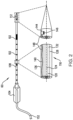
- Fig. 1 is a schematic illustration of an apparatus 20 being used for a cryogenic medical procedure, according to an embodiment of the present invention.
- the procedure assumed in the following description is on a breast tumor, but it will be understood that apparatus 20 may be used for other procedures, such as on a prostate or kidney tumor, and all such procedures are considered to be comprised within the scope of the appended claims.
- the cryogenic procedure on the breast tumor is performed in two phases: a first phase in which a distal end 112 of a probe 60 is reduced in temperature to an initial temperature, typically between approximately -10°C and approximately -30°C, and a second phase in which the distal end temperature is further reduced to a subsequent temperature lower than the initial temperature.
- the subsequent temperature is approximately - 160 ⁇ 10°C.
- the procedure is performed by a physician 24 on a patient 28, and the physician is able to observe results of the procedure on a display 32 comprised in apparatus 20.
- the first phase of the procedure on the breast tumor includes performing an ultrasound scan of the breast of patient 28, and presenting results of the scan on display 32.
- the scan is normally performed by an ultrasound professional, other than physician 24. Details of the ultrasound scan are not relevant to the present disclosure, and for simplicity the ultrasound professional is not shown in Fig. 1 .
- the first phase may include performing a CT (computerized tomography) scan of the breast.)
- Apparatus 20 is controlled by a processor 36, which is coupled to a memory 40 wherein is stored software 44 for operation of the apparatus.
- Processor 36 and memory 40 are installed in an operating console 42.
- Software 44 in memory 40 may be downloaded to the processor in electronic form, over a network, for example. Alternatively or additionally, the software may be provided on non-transitory tangible media, such as optical, magnetic, or electronic storage media.
- Software 44 includes software for an apparatus operation algorithm 48, comprising steps executed by the processor in operating apparatus 20. Apparatus operation algorithm 48 is described in more detail below.
- apparatus 20 is used to inject a cryogenic fluid 52, initially typically held in a pump 56, also herein termed a fluid supply 56, into probe 60 which has distal end 112 inserted into proximity with the tumor.
- Pump 56 comprises a Dewar 72, which holds cryogenic fluid 52 that is retained in liquid form in a lower space 80 of the Dewar. Above the liquid in the Dewar, in an upper space 84, there is gas formed by evaporation of the cryogenic liquid.
- a pump similar to pump 56 is described in US Patent Application 16/785,686 titled "Cryogen Pump" to Hilleli et al.
- Fluid 52 is initially in the form of a liquid, but during the procedure the fluid may change from a liquid to a liquid/gas mixture, or even to a completely gaseous state.
- cryogenic fluid 52 is herein assumed, by way of example, to comprise liquid or gaseous nitrogen.
- other cryogenic fluids such as cryogenic argon, may be used in apparatus 20, and all such cryogenic fluids are assumed to be comprised within the scope of the appended claims.
- Pump 56 is connected to probe 60, which physician 24 manipulates so as to correctly position the probe distal end with respect to the tumor. (The manipulation is typically assisted by the physician observing the ultrasound scan referred to above.) Probe 60 is described in more detail below.
- Fig. 2 is a schematic diagram of probe 60, according to an embodiment of the present invention.
- Probe 60 comprises a handle 104, which is attached to a shaft 108 of the probe at a shaft proximal end.
- Shaft 108 terminates in a pointed distal end 112, which enables the shaft to pierce tissue, such as a section of a breast of patient 28.
- Markings 102 on an external wall of the shaft indicate distances from the distal end, and may be used by physician 24 in placement of probe 60 during the procedure.
- shaft 108 comprises three concentric tubes, typically formed from thin-walled stainless steel.
- a first, inner, tube 120 encloses a central lumen 124, and the inner tube is surrounded by a second tube 128.
- the first tube and the second tube are separated by an intermediate space 132.
- a third, outer, tube 136 surrounds second tube 128, and the second and third tubes are separated by a space 140. Markings 102 may be placed on an external wall of tube 136.
- a temperature sensor 144 typically a thermocouple or a thermistor, is fixedly located within distal end 112, typically in proximity to a heat exchanger 146, surrounding tube 120, that is positioned at the distal end.
- Cabling 148 for the temperature sensor is typically positioned in space 140. The cabling is connected to processor 36, and enables the processor to measure a temperature sensed by sensor 144.
- space 140 between the second and third tubes of shaft 108, is maintained in a sealed evacuated state.
- central lumen 124 is used to convey cryogenic fluid from pump 56 to distal end 112
- intermediate space 132 is used to return cryogenic fluid from the distal end to the pump.
- a flexible tube 152 having an internal structure generally similar to the internal structure of shaft 108, is coupled to the shaft via handle 104. Lumens within tube 152 are configured to convey cryogenic fluid from pump 56 to central lumen 124, and to transfer returning cryogenic fluid from intermediate space 132 to the pump.
- Fig. 3 is a schematic block diagram of apparatus 20, illustrating how the elements of the apparatus are connected together, according to an embodiment of the present invention.
- the block diagram illustrates the flow of cryogenic fluid, and the flow of signal data, between the elements.
- Processor 36 controls operation of apparatus 20, by providing pump motor control signals to motor 68.
- the motor operates pump 56 so that cryogenic fluid is expelled, at a flow rate which depends on the revolution rate of the motor, from Dewar 72.
- the speed of the motor i.e., the motor's revolution rate
- Flow rate is herein also termed rate of delivery.
- flow rates are given as rpm (revolutions per minute), and in an embodiment the pump has a motor with a gear ratio of 1:50, so that 3,000 rpm of the motor corresponds to 60 rpm of the pump.
- the expelled cryogenic fluid flows out of the Dewar, via flexible tube 152, handle 104, and lumen 124 of tube 120, to distal end 112.
- processor 36 is a PID (proportional-integral-derivative) controller.
- the cryogenic fluid returns from distal end 112, typically as a liquid/gas mixture, via space 132 in probe 60, handle 104, and flexible tube 152 to Dewar 72.
- temperature sensor 144 at the distal end of the probe, provides a signal indicative of the temperature of the probe tip to processor 36.
- Processor 36 also receives, from a pressure sensor 100 in handle 104, a signal indicative of the pressure of the cryogenic fluid entering lumen 124.
- Sensor 100 is located in handle 104, typically in proximity to internal tube 120, so that the sensor is in contact with the entering cryogenic fluid.
- Processor 36 uses the signals from the pressure sensor and the temperature sensor to operate algorithm 48, which enables the processor to generate an output signal controlling pump motor 68.
- the output signal that is transferred to the pump motor controls the revolution rate of the motor and thus the flow rate of the cryogenic fluid expelled from Dewar 72.
- Fig. 4 is a flowchart of operations taken by processor 36 in executing algorithm 48 during the first phase of the procedure, according to an embodiment of the present invention.
- PID proportional-integral-derivative
- a first step 150 parameters for processor 36, herein, as stated above, assumed to comprise a PID controller, are input to the processor.
- the processor also sets a minimum motor speed M m , corresponding to a minimum flow rate or a minimum rate of delivery, that the processor applies to pump motor 68 according to steps of the flowchart.
- M m a minimum motor speed
- the minimum motor speed is set at 224 rpm.
- f(P) is configured so that if P increases the maximum motor speed M u falls, so that the maximum flow rate falls, and if P decreases M u increases, so that the maximum flow rate increases.
- both derivatives dM u dP and dP dt are negative.
- physician 24 inserts probe 60 into patient 28, and activates pump 56 to inject cryogenic fluid into the probe.
- a first decision step 158 the processor compares the temperature T measured by sensor 144 with guard temperature T g , by evaluating the expression T ⁇ T g
- step 166 the processor compares temperature T with the target temperature T t by evaluating the expression T ⁇ T t
- step 166 returns positive, i.e., temperature T is less than target temperature T t , then in a decrease motor speed step 168, the processor calculates a decreased target motor speed M T , corresponding to a decreased target flow rate.
- step 166 returns negative, i.e., temperature T is greater than or equal to target temperature T t , then in an increase motor speed step 170, the processor calculates an increased target motor speed M T , corresponding to an increased target flow rate.
- K 2 640 rpm.
- Control from steps 168 and 170 continues at a maximum speed step 172.
- step 172 the processor accesses the value of pressure P provided by pressure sensor 100, and uses the value to calculate the maximum motor speed M u according to equation (2).
- a third decision step 174 the processor compares the motor speeds M T and M u , i.e., the processor compares the target flow rate and the maximum flow rate, by evaluating the expression M T ⁇ M u
- the processor proceeds to a second set flow rate step 178, wherein the processor sets the motor speed to the target motor speed M T . I.e., the processor sets the flow rate to the target flow rate.
- the steps of the flowchart, corresponding to algorithm 48, are performed during the first phase of the procedure described with reference to Fig. 1 .
- the first phase terminates when the physician ceases iterating the flowchart steps, i.e., halts operation of algorithm 48.
- the physician may proceed to the second phase of the procedure, to further lower the temperature of distal end 112.
- algorithm 48 is not activated, and the lower temperature is typically achieved by increasing the flow rate of pump 56.
- Fig. 5 is a set of schematic graphs obtained during operation of the flowchart of Fig. 4 , i.e., during activation of algorithm 48, according to an embodiment of the present invention.
- a first graph 200 plots temperature of distal end 112, as measured by sensor 144, vs. time; a second graph 204 plots pressure, as measured by sensor 100, vs. time; and a third graph 208 plots cryogen flow rate as measured by the pump motor speed, corresponding to the input from processor 36 to pump 68, vs. time.
- the flow rate and the motor speed are low and approximately constant, corresponding to first flow rate step 162 of the flowchart.
- the low flow rate allows the distal end temperature to increase above guard temperature T g and the pressure may also increase.
- the pressure is initially low so that there is a high value for the maximum flow rate and maximum motor speed M u (calculated in step 172), and because T is less then T t , decision 166 returns positive and the processor begins to decrease the flow rate and motor speed in step 168.
- Decision 174 then returns positive so this situation corresponds to the second flow rate step 178, where the flow rate is set at the target flow rate by the motor speed being set at the target speed M T .
- the processor begins to increase the target flow rate and target motor speed M T in step 170. Since the maximum flow rate and maximum motor speed M u are still high decision 174 returns positive so that second flow rate step 178 still applies, and the increased target flow rate and target motor speed M T , can continue.
- the increased flow rate continues until the pressure, because of the increased flow rate, sharply increases, as shown, for example, in graph 204 at time 80.
- the high pressure relieves any incipient vapor lock, since at the high pressure any liquid cryogen is more compressible than at low pressures. Furthermore, near or beyond the critical pressure the cryogen is, or behaves as, a supercritical fluid. Thus, the cryogen flows more easily in the probe.
- the increased flow rate also causes the temperature to sharply drop below T g , as shown in graph 200.
- the increased pressure means that there is now a low value for the maximum flow rate set by the maximum motor speed M u , so that decision 174 returns negative, and third flow rate step 182 applies.
- the flow rate consequently drops sharply, corresponding to the low maximum motor speed M u , and this flow rate continues to a time 216.
- the process implemented by processor 36 is an iterative process, and there is one iteration between times 212 and 216.
- the temperature of the distal end oscillates about a target temperature T t .
- Graph 204 also illustrates that the pressure measured by pressure sensor 100 oscillates between relatively low values of approximately 100 psi and relatively high values of approximately 300 psi.
- the oscillations of the temperature, pressure, and flow rate are limited, the respective upper and lower limits depending, inter alia, on the minimum flow rate and motor speed M m set as well as the maximum flow rate and motor speed M u given by equation (3).
- the oscillations also depend on the coefficients of the PID controller terms used in equation (1).
- the amplitude of the temperature oscillation of the distal end, when it is oscillating about the target temperature T t is approximately 10°C, wherein the amplitude is the difference in temperature between a distal end local maximum temperature and a distal end local minimum temperature.
- the terms “about” or “approximately” for any numerical values or ranges indicate a suitable dimensional tolerance that allows the part or collection of components to function for its intended purpose as described herein. More specifically, “about” or “approximately” may refer to the range of values ⁇ 20% of the recited value, e.g. " approximately 80%” may refer to the range of values from 64% to 96%.
Abstract
Apparatus, including a probe, containing a first lumen and a second lumen and having a distal end that contacts tissue of a living subject. A fluid supply delivers a cryogenic fluid through the first lumen to the distal end and receives cryogenic fluid returning via the second lumen. A temperature sensor is located at the distal end. A pressure sensor located at a proximal end of the first lumen measures a pressure of the cryogenic fluid. A processor controls a delivery rate of the cryogenic fluid from the fluid supply, so that, when a temperature measured by the temperature sensor is less than a preset guard temperature, the delivery rate is a preset low rate, and when the temperature measured by the temperature sensor is greater than or equal to the preset guard temperature, the delivery rate is set in response to a pressure measured by the pressure sensor.
Description
- This invention relates generally to cryogen flow, and particularly to controlling the flow of a cryogen efficiently. More particular the present invention relates to an apparatus and method for controlling the flow of a cryogen efficiently.
- Pumps for cryogenic materials have to be able to overcome limitations caused by the extreme cold, such as reduced elasticity, so as to operate effectively. Vapor lock is also a problem for cryogenic pumps. Systems and methods for improving the efficiency of cryogenic pumps are known in the art.
-
U. S. Patent 6,007,571 to Neilson, et al. , describes a liquid coolant supply system for supplying a liquid coolant to a thermal therapy catheter. The system has a sensor control unit that includes a pump, a cooling device, a temperature sensor and a pressure sensor. -
U. S. Patent 6,471,694 to Kudaravalli, et al. , describes a control system for cryosurgery. Procedures are disclosed for bringing the system to a desired operational state, for controlling the operation by controlling refrigerant flow rate, for performing safety checks, and for achieving safe shutdown. -
U. S. Patent 6,939,346 to Kannenberg, et al. , describes apparatus for controlling a temperature-controlled probe. The apparatus includes a controller coupled to a probe, and a thermal element to vary probe temperature. -
U. S. Patent 7,357,797 to Ryba , describes a system for varying return pressure to control tip temperature of a cryoablation catheter. In the system, the distal end of a refrigerant supply line is positioned in a central lumen and is distanced from the catheter tube's distal tip to establish an expansion chamber. -
U. S. Patent 7,731,711, to Levin , describes flow in a central lumen of a cryosurgical instrument that has an oscillating character. In the instrument a refrigerant is provided on the internal surface of a distal cryotip in the form of separated portions. -
U. S. Patent 7,780,657, to Abboud, et al. , describes a cooling system. A console of the system includes a first cooling system directing coolant to a medical device at a first temperature along a coolant supply line and a second cooling system chilling the coolant within the coolant supply line to a temperature below the first temperature before the coolant reaches a connection point. -
U. S. Patent 7,921,657 to Littrup, et al. , describes a system for cooling an object with a cryogen having a critical point defined by a critical-point pressure and a critical-point temperature. A pressure of the cryogen is raised above a pressure value determined to provide the cryogen at a reduced molar volume that prevents vapor lock. -
U. S. Patent 10,098,685 to Lalonde, et al. -
U. S. Patent 10,213,244 to Fourkas, et al. -
U. S. Patent 10,485,602 to Geiselhart -
U. S. Patent 10,828,080 to George, et al. -
U. S. Patent Application 2005/0159735 to Walton, et al. , describes an apparatus for automatic operation of a refrigeration system that provides refrigeration power to a catheter for tissue ablation or mapping. A primary refrigeration system can be open loop or closed loop, and a precool loop will typically be closed loop. -
U. S. Patent Application 2005/0198972 to Lentz, et al. , describes a pressure-temperature control for a cryoablation catheter system. A temperature sensor is mounted at the distal end of a cryo-catheter. A system controller is in electronic communication with both a pressure regulator and the temperature sensor. -
U. S. Patent Application 2019/0175395 Kim, et al. , describes a device and a method for cooling living tissues for a medical purpose and other purposes. The cooling device comprises: a container configured to accommodate a cooling medium and thermally coupled with the cooling medium by directly contacting the cooling medium. - An aspect of the present invention provides apparatus, comprising: a probe, containing a first lumen and a second lumen and having a distal end configured to contact tissue of a living subject; a fluid supply coupled to deliver a cryogenic fluid through the first lumen to the distal end of the probe and to receive the cryogenic fluid returning via the second lumen from the probe; a temperature sensor located at the distal end; a pressure sensor located at a proximal end of the first lumen and configured to measure a pressure of the cryogenic fluid therein; and a processor configured to control a rate of delivery of the cryogenic fluid from the fluid supply, so that, when a temperature measured by the temperature sensor is less than a preset guard temperature, the rate of delivery is a preset low rate, and when the temperature measured by the temperature sensor is greater than or equal to the preset guard temperature, the rate of delivery is set in response to a pressure measured by the pressure sensor.
- In a disclosed embodiment, when the temperature measured by the temperature sensor is greater than or equal to the preset guard temperature, the rate of delivery is set in response to the temperature.
- In a further disclosed embodiment, when the temperature measured by the temperature sensor is greater than or equal to the preset guard temperature, the rate of delivery is set in response to a preset target temperature greater than the preset guard temperature. Typically, the preset target temperature is in a range from -10°C to -50°C.
- In a yet further disclosed embodiment, when the temperature measured by the temperature sensor is greater than or equal to the preset guard temperature, the rate of delivery is less than or equal to a maximum rate of delivery calculated from a preset function of the pressure. Typically, a first derivative of the preset function at the pressure measured by the pressure sensor is negative.
- In an alternative embodiment, when the temperature measured by the temperature sensor is greater than or equal to the preset guard temperature, the rate of delivery is set in response to the pressure compared to a parametric pressure selected in response to a critical pressure of the cryogenic fluid. Typically, the parametric pressure is greater than the critical pressure.
- In a further alternative embodiment, the processor is a proportional-integral-derivative (PID) controller. Typically, the PID controller is operated as a PI controller.
- There is further provided, according to another aspect of the present invention, a method, comprising: providing a probe, containing a first lumen and a second lumen and having a distal end configured to contact tissue of a living subject; coupling a fluid supply to deliver a cryogenic fluid through the first lumen to the distal end of the probe and to receive the cryogenic fluid returning via the second lumen from the probe; locating a temperature sensor at the distal end; locating a pressure sensor at a proximal end of the first lumen and configuring the sensor to measure a pressure of the cryogenic fluid therein; and controlling a rate of delivery of the cryogenic fluid from the fluid supply, so that, when a temperature measured by the temperature sensor is less than a preset guard temperature, the rate of delivery is a preset low rate, and when the temperature measured by the temperature sensor is greater than or equal to the preset guard temperature, the rate of delivery is set in response to a pressure measured by the pressure sensor.
- There is further provided, according to yet another aspect of the present invention, apparatus, comprising: a probe, containing a first lumen and a second lumen and having a distal end configured to contact tissue of a living subject; a fluid supply coupled to deliver a cryogenic fluid through the first lumen to the distal end of the probe and to receive the cryogenic fluid returning via the second lumen from the probe; a temperature sensor located at the distal end; a pressure sensor located at a proximal end of the first lumen and configured to measure a pressure of the cryogenic fluid therein; and a processor configured to control a rate of delivery of the cryogenic fluid from the fluid supply, so that, in response to a preset target temperature for the distal end and the pressure measured by the pressure sensor, a temperature measured by the temperature sensor oscillates by a preset amplitude about the preset target temperature.
- Typically, the processor is configured to control the rate of delivery of the cryogenic fluid in response to a ratio of the pressure measured by the pressure sensor to a predetermined pressure. The predetermined pressure may be greater than a critical pressure of the cryogenic fluid.
- Typically, the rate of delivery is at least a preset minimum rate of delivery.
- Typically, the processor is a proportional-integral-derivative controller, and coefficient values of the controller are selected so that the temperature oscillates by the preset amplitude.
- Typically, the preset amplitude is between 8°C and 12°C.
- The present disclosure will be more fully understood from the following detailed description of the embodiments thereof, taken together with the drawings, in which:
-
Fig. 1 is a schematic illustration of an apparatus being used for a cryogenic medical procedure, according to an embodiment of the present invention; -
Fig. 2 is a schematic diagram of a probe, according to an embodiment of the present invention; -
Fig. 3 is a schematic block diagram of apparatus, illustrating how the elements of the apparatus are connected together, according to an embodiment of the present invention; -
Fig. 4 is a flowchart of operations taken by a processor in executing an algorithm during a first phase of a procedure, according to an embodiment of the present invention;, and -
Fig. 5 is a set of schematic graphs obtained during operation of the flowchart ofFig. 4 , according to an embodiment of the present invention. - One of the problems that occurs in operation of a cryogenic probe in a cryogenic procedure is the reduced operational efficiency, or even complete failure to operate, of the probe due to vapor lock. Vapor lock, the reduction or even complete cessation in flow rate of a liquid, occurs in a cryogenic system when cryogenic vapor from evaporated cryogenic liquid constricts or halts the flow of the liquid. The reduction in flow prevents the probe from cooling tissue contacting the probe during the procedure. The vapor lock problem is exacerbated if the cryogenic liquid is effectively uncompressible, and this is the case if the probe is operated at a low pressure, very different from the pressure value of the critical point of the cryogen being used. For example, liquid nitrogen has a critical pressure of approximately 33.5 atm (atmospheres) and so is relatively incompressible at pressures in the approximate range of 1-10 atm.
- Embodiments of the invention overcome the vapor lock problem for a cryogenic probe, while mostly operating the probe at a relatively low pressure, by configuring the probe to periodically operate for short periods of time at a high pressure, close to the critical pressure of the cryogen, herein assumed to be liquid nitrogen. In these periods the liquid nitrogen is relatively compressible, and is able to flow more freely to relieve any incipient vapor lock.
- To realize the high pressure short periods, embodiments of the invention configure the temperature of the distal end of the probe to oscillate about a target temperature, rather than attempting to maintain the distal end at the target temperature. A processor measures a pressure of the cryogen in the probe, as well as a temperature of the distal end. The processor uses the measured temperature and pressure values to control a rate of rotation of a pump of the cryogen, i.e., to control a flow rate at which cryogen is expelled from the pump into the probe, and the processor is configured so that the flow rate - the rate of rotation of the pump - varies in an oscillatory manner, between high and low values of the flow rate.
- The oscillations of flow rate provide the short time periods of high pressure described above, as well as the oscillations about the target temperature.
- An embodiment of the present invention provides apparatus, consisting of a probe, containing a first lumen and a second lumen and having a distal end configured to contact tissue of a living subject. There is a fluid supply that is coupled to deliver a cryogenic fluid through the first lumen to the distal end of the probe and to receive the cryogenic fluid returning via the second lumen from the probe.
- A temperature sensor is located at the distal end of the probe, and a pressure sensor is located at a proximal end of the first lumen. The pressure sensor measures a pressure of the cryogenic fluid flowing in the first lumen.
- A processor is configured to control a rate of delivery of the cryogenic fluid from the fluid supply, so that, when a temperature measured by the temperature sensor is less than a preset guard temperature, the rate of delivery is a preset low rate, and when the temperature measured by the temperature sensor is greater than or equal to the preset guard temperature, the rate of delivery is set in response to a target temperature of the distal end and to a pressure measured by the pressure sensor.
- In the following description, like elements in the drawings are identified by like numerals.
- Reference is now made to
Fig. 1 , which is a schematic illustration of anapparatus 20 being used for a cryogenic medical procedure, according to an embodiment of the present invention. By way of example the procedure assumed in the following description is on a breast tumor, but it will be understood thatapparatus 20 may be used for other procedures, such as on a prostate or kidney tumor, and all such procedures are considered to be comprised within the scope of the appended claims. - The cryogenic procedure on the breast tumor is performed in two phases: a first phase in which a
distal end 112 of aprobe 60 is reduced in temperature to an initial temperature, typically between approximately -10°C and approximately -30°C, and a second phase in which the distal end temperature is further reduced to a subsequent temperature lower than the initial temperature. In one embodiment the subsequent temperature is approximately - 160±10°C. - The procedure is performed by a
physician 24 on apatient 28, and the physician is able to observe results of the procedure on adisplay 32 comprised inapparatus 20. (Typically the first phase of the procedure on the breast tumor includes performing an ultrasound scan of the breast ofpatient 28, and presenting results of the scan ondisplay 32.) The scan is normally performed by an ultrasound professional, other thanphysician 24. Details of the ultrasound scan are not relevant to the present disclosure, and for simplicity the ultrasound professional is not shown inFig. 1 . Alternatively or additionally, the first phase may include performing a CT (computerized tomography) scan of the breast.) -
Apparatus 20 is controlled by aprocessor 36, which is coupled to amemory 40 wherein is storedsoftware 44 for operation of the apparatus.Processor 36 andmemory 40 are installed in an operatingconsole 42.Software 44 inmemory 40 may be downloaded to the processor in electronic form, over a network, for example. Alternatively or additionally, the software may be provided on non-transitory tangible media, such as optical, magnetic, or electronic storage media.Software 44 includes software for anapparatus operation algorithm 48, comprising steps executed by the processor in operatingapparatus 20.Apparatus operation algorithm 48 is described in more detail below. - In the first and the second phase of the procedure on the breast tumor,
apparatus 20 is used to inject acryogenic fluid 52, initially typically held in apump 56, also herein termed afluid supply 56, intoprobe 60 which hasdistal end 112 inserted into proximity with the tumor.Pump 56 comprises aDewar 72, which holdscryogenic fluid 52 that is retained in liquid form in alower space 80 of the Dewar. Above the liquid in the Dewar, in anupper space 84, there is gas formed by evaporation of the cryogenic liquid. A pump similar to pump 56 is described inUS Patent Application 16/785,686 titled "Cryogen Pump" to Hilleli et al. -
Fluid 52 is initially in the form of a liquid, but during the procedure the fluid may change from a liquid to a liquid/gas mixture, or even to a completely gaseous state. Except where otherwise stated,cryogenic fluid 52 is herein assumed, by way of example, to comprise liquid or gaseous nitrogen. However, it will be understood that other cryogenic fluids, such as cryogenic argon, may be used inapparatus 20, and all such cryogenic fluids are assumed to be comprised within the scope of the appended claims.Pump 56 is connected to probe 60, whichphysician 24 manipulates so as to correctly position the probe distal end with respect to the tumor. (The manipulation is typically assisted by the physician observing the ultrasound scan referred to above.)Probe 60 is described in more detail below. -
Fig. 2 is a schematic diagram ofprobe 60, according to an embodiment of the present invention.Probe 60 comprises ahandle 104, which is attached to ashaft 108 of the probe at a shaft proximal end.Shaft 108 terminates in a pointeddistal end 112, which enables the shaft to pierce tissue, such as a section of a breast ofpatient 28. (Markings 102 on an external wall of the shaft indicate distances from the distal end, and may be used byphysician 24 in placement ofprobe 60 during the procedure.) As shown in asection 116,shaft 108 comprises three concentric tubes, typically formed from thin-walled stainless steel. A first, inner,tube 120 encloses acentral lumen 124, and the inner tube is surrounded by asecond tube 128. The first tube and the second tube are separated by anintermediate space 132. A third, outer,tube 136 surroundssecond tube 128, and the second and third tubes are separated by aspace 140.Markings 102 may be placed on an external wall oftube 136. - A
temperature sensor 144, typically a thermocouple or a thermistor, is fixedly located withindistal end 112, typically in proximity to aheat exchanger 146, surroundingtube 120, that is positioned at the distal end. Cabling 148 for the temperature sensor is typically positioned inspace 140. The cabling is connected toprocessor 36, and enables the processor to measure a temperature sensed bysensor 144. - In operation of
apparatus 20,space 140, between the second and third tubes ofshaft 108, is maintained in a sealed evacuated state. As is explained in more detail below,central lumen 124 is used to convey cryogenic fluid frompump 56 todistal end 112, andintermediate space 132 is used to return cryogenic fluid from the distal end to the pump. - A
flexible tube 152, having an internal structure generally similar to the internal structure ofshaft 108, is coupled to the shaft viahandle 104. Lumens withintube 152 are configured to convey cryogenic fluid frompump 56 tocentral lumen 124, and to transfer returning cryogenic fluid fromintermediate space 132 to the pump. -
Fig. 3 is a schematic block diagram ofapparatus 20, illustrating how the elements of the apparatus are connected together, according to an embodiment of the present invention. The block diagram illustrates the flow of cryogenic fluid, and the flow of signal data, between the elements. -
Processor 36 controls operation ofapparatus 20, by providing pump motor control signals tomotor 68. On activation, the motor operatespump 56 so that cryogenic fluid is expelled, at a flow rate which depends on the revolution rate of the motor, fromDewar 72. Thus, in the description herein, except where otherwise indicated, the speed of the motor, i.e., the motor's revolution rate, is directly proportional to the flow rate of the expelled cryogenic fluid, so that large revolution rates correspond to large flow rates, and small revolution rates correspond to small flow rates. Flow rate is herein also termed rate of delivery. - In the description herein flow rates are given as rpm (revolutions per minute), and in an embodiment the pump has a motor with a gear ratio of 1:50, so that 3,000 rpm of the motor corresponds to 60 rpm of the pump. When the fluid is 100% liquid an approximate conversion factor for the pump rpm to the flow rate is: 60 rpm = 0.36 liters/minute.
- The expelled cryogenic fluid flows out of the Dewar, via
flexible tube 152, handle 104, andlumen 124 oftube 120, todistal end 112. - In a disclosed
embodiment processor 36 is a PID (proportional-integral-derivative) controller. - The cryogenic fluid returns from
distal end 112, typically as a liquid/gas mixture, viaspace 132 inprobe 60, handle 104, andflexible tube 152 toDewar 72. - As indicated in the figure,
temperature sensor 144, at the distal end of the probe, provides a signal indicative of the temperature of the probe tip toprocessor 36.Processor 36 also receives, from apressure sensor 100 inhandle 104, a signal indicative of the pressure of the cryogenicfluid entering lumen 124.Sensor 100 is located inhandle 104, typically in proximity tointernal tube 120, so that the sensor is in contact with the entering cryogenic fluid. -
Processor 36 uses the signals from the pressure sensor and the temperature sensor to operatealgorithm 48, which enables the processor to generate an output signal controllingpump motor 68. The output signal that is transferred to the pump motor controls the revolution rate of the motor and thus the flow rate of the cryogenic fluid expelled fromDewar 72. -
Fig. 4 is a flowchart of operations taken byprocessor 36 in executingalgorithm 48 during the first phase of the procedure, according to an embodiment of the present invention. In the description of the flowchart,processor 36 is assumed to comprise a PID (proportional-integral-derivative) controller, having an output given by equation (1):
- A person having ordinary skill in the art will be able to adapt the flowchart description without undue experimentation, mutatis mutandis, for processors other than PID controllers.
- In a
first step 150, parameters forprocessor 36, herein, as stated above, assumed to comprise a PID controller, are input to the processor. In the following description the PID controller is assumed to have coefficient values of Kc = 0.1 and ti=0.05, and td=0, i.e.,processor 36 operates as a PI controller, and those having ordinary skill in the art will be able to adapt the description, without undue experimentation, for other values of Kc, ti, and td. - In
step 150processor 36 is provided with a target temperature Tt, which is a nominal temperature to whichdistal end 112 is cooled. Temperature Tt is typically in a range from -10°C to -50°C, although in some embodiments Tt is outside this range.Processor 36 is also provided with a guard temperature Tg, which is a temperature less than Tt, that acts as a nominal temperature limit for the distal end. In one embodiment when Tt = -20°C, Tg = -23°C. - The processor also sets a minimum motor speed Mm, corresponding to a minimum flow rate or a minimum rate of delivery, that the processor applies to pump
motor 68 according to steps of the flowchart. In one embodiment the minimum motor speed is set at 224 rpm. - In
initial step 150 the processor is also provided with a function f(P) that the processor uses to calculate a maximum motor speed Mu, corresponding to a maximum flow rate or a maximum rate of delivery, to be applied to the pump motor, i.e.,
pressure sensor 100. - In an embodiment of the invention f(P) is configured so that if P increases the maximum motor speed Mu falls, so that the maximum flow rate falls, and if P decreases Mu increases, so that the maximum flow rate increases. In the embodiment both derivatives


- In a disclosed embodiment equation (2) is set as equation (3):

apparatus 20; and
K1 is a proportionality constant used to convert the expression on the right side of equation (3) to the units of Mu. - From equation (3) the gradient


- In one example of the disclosed embodiment, when P is measured in psi (pounds per square inch) and Mu is measured in rpm (revolutions per minute), K1 = 960 rpm and Parb = 800 psi, so that

- In a
procedure initialization step 154,physician 24inserts probe 60 intopatient 28, and activates pump 56 to inject cryogenic fluid into the probe. - In a
first decision step 158, the processor compares the temperature T measured bysensor 144 with guard temperature Tg, by evaluating the expression
- If expression (4) returns positive, i.e., temperature T is less than guard temperature Tg, then the processor proceeds to a first set
flow rate step 162, wherein the processor sets the motor speed to the minimum speed Mm, corresponding to setting the flow rate to the minimum flow rate. Control then returns todecision step 158. - If expression (4) returns negative, i.e., temperature T is greater than or equal to the guard temperature, then control continues to a
second decision step 166. Instep 166 the processor compares temperature T with the target temperature Tt by evaluating the expression
- If
step 166 returns positive, i.e., temperature T is less than target temperature Tt, then in a decreasemotor speed step 168, the processor calculates a decreased target motor speed MT, corresponding to a decreased target flow rate. - If
step 166 returns negative, i.e., temperature T is greater than or equal to target temperature Tt, then in an increasemotor speed step 170, the processor calculates an increased target motor speed MT, corresponding to an increased target flow rate. - In
steps 
- In a disclosed embodiment, K2 = 640 rpm.
- Control from
steps maximum speed step 172. - In
step 172 the processor accesses the value of pressure P provided bypressure sensor 100, and uses the value to calculate the maximum motor speed Mu according to equation (2). - In a
third decision step 174, the processor compares the motor speeds MT and Mu, i.e., the processor compares the target flow rate and the maximum flow rate, by evaluating the expression
- If expression (7) returns positive, i.e., the target motor speed MT is less than the maximum motor speed Mu, then the processor proceeds to a second set
flow rate step 178, wherein the processor sets the motor speed to the target motor speed MT. I.e., the processor sets the flow rate to the target flow rate. - If expression (7) returns negative, i.e., motor speed MT is equal to or greater than maximum speed Mu, then the processor proceeds to a third set
flow rate step 182, wherein the processor sets the motor speed to the maximum motor speed Mu. I.e., the processor sets the flow rate to the maximum flow rate. - The flowchart of
Fig. 4 reiterates by control from theflow rate steps decision step 158. - The steps of the flowchart, corresponding to
algorithm 48, are performed during the first phase of the procedure described with reference toFig. 1 . The first phase terminates when the physician ceases iterating the flowchart steps, i.e., halts operation ofalgorithm 48. At this point the physician may proceed to the second phase of the procedure, to further lower the temperature ofdistal end 112. In thesecond phase algorithm 48 is not activated, and the lower temperature is typically achieved by increasing the flow rate ofpump 56. -
Fig. 5 is a set of schematic graphs obtained during operation of the flowchart ofFig. 4 , i.e., during activation ofalgorithm 48, according to an embodiment of the present invention. Afirst graph 200 plots temperature ofdistal end 112, as measured bysensor 144, vs. time; asecond graph 204 plots pressure, as measured bysensor 100, vs. time; and athird graph 208 plots cryogen flow rate as measured by the pump motor speed, corresponding to the input fromprocessor 36 to pump 68, vs. time. - As is illustrated in the graphs, when the distal end temperature T is below the guard temperature Tg, the flow rate and the motor speed are low and approximately constant, corresponding to first
flow rate step 162 of the flowchart. The low flow rate allows the distal end temperature to increase above guard temperature Tg and the pressure may also increase. Typically, as is illustrated at atime 212, exiting from guard temperature Tg the pressure is initially low so that there is a high value for the maximum flow rate and maximum motor speed Mu (calculated in step 172), and because T is less then Tt,decision 166 returns positive and the processor begins to decrease the flow rate and motor speed instep 168.Decision 174 then returns positive so this situation corresponds to the secondflow rate step 178, where the flow rate is set at the target flow rate by the motor speed being set at the target speed MT. - However, when T is greater than or equal to Tt, the processor begins to increase the target flow rate and target motor speed MT in
step 170. Since the maximum flow rate and maximum motor speed Mu are stillhigh decision 174 returns positive so that secondflow rate step 178 still applies, and the increased target flow rate and target motor speed MT, can continue. - The increased flow rate continues until the pressure, because of the increased flow rate, sharply increases, as shown, for example, in
graph 204 attime 80. The high pressure relieves any incipient vapor lock, since at the high pressure any liquid cryogen is more compressible than at low pressures. Furthermore, near or beyond the critical pressure the cryogen is, or behaves as, a supercritical fluid. Thus, the cryogen flows more easily in the probe. - The increased flow rate also causes the temperature to sharply drop below Tg, as shown in
graph 200. The increased pressure means that there is now a low value for the maximum flow rate set by the maximum motor speed Mu, so thatdecision 174 returns negative, and thirdflow rate step 182 applies. The flow rate consequently drops sharply, corresponding to the low maximum motor speed Mu, and this flow rate continues to atime 216. - As is apparent from the graphs, the process implemented by
processor 36 is an iterative process, and there is one iteration betweentimes graph 200, the temperature of the distal end oscillates about a target temperature Tt. Graph 204 also illustrates that the pressure measured bypressure sensor 100 oscillates between relatively low values of approximately 100 psi and relatively high values of approximately 300 psi. The oscillations of the temperature, pressure, and flow rate are limited, the respective upper and lower limits depending, inter alia, on the minimum flow rate and motor speed Mm set as well as the maximum flow rate and motor speed Mu given by equation (3). Thus, the oscillations also depend on the coefficients of the PID controller terms used in equation (1). - In an embodiment of the invention, the amplitude of the temperature oscillation of the distal end, when it is oscillating about the target temperature Tt, is approximately 10°C, wherein the amplitude is the difference in temperature between a distal end local maximum temperature and a distal end local minimum temperature.
- As used herein, the terms "about" or "approximately" for any numerical values or ranges indicate a suitable dimensional tolerance that allows the part or collection of components to function for its intended purpose as described herein. More specifically, "about" or "approximately" may refer to the range of values ±20% of the recited value, e.g. " approximately 80%" may refer to the range of values from 64% to 96%.
- It will be appreciated that the embodiments described above are cited by way of example, and that the present invention includes both combinations and subcombinations of the various features described hereinabove, as well as variations and modifications thereof which would occur to persons skilled in the art upon reading the foregoing description and which are not disclosed in the prior art, within the scope of the appended claims.
Claims (15)
- Apparatus, comprising:a probe, containing a first lumen and a second lumen and having a distal end configured to contact tissue of a living subject;a fluid supply coupled to deliver a cryogenic fluid through the first lumen to the distal end of the probe and to receive the cryogenic fluid returning via the second lumen from the probe;a temperature sensor located at the distal end;a pressure sensor located at a proximal end of the first lumen and configured to measure a pressure of the cryogenic fluid therein; anda processor configured to control a rate of delivery of the cryogenic fluid from the fluid supply, so that, when a temperature measured by the temperature sensor is less than a preset guard temperature, the rate of delivery is a preset low rate, and when the temperature measured by the temperature sensor is greater than or equal to the preset guard temperature, the rate of delivery is set in response to a pressure measured by the pressure sensor.
- The apparatus according to claim 1, wherein when the temperature measured by the temperature sensor is greater than or equal to the preset guard temperature, the rate of delivery is set in response to the temperature.
- The apparatus according to claim 1, wherein when the temperature measured by the temperature sensor is greater than or equal to the preset guard temperature, the rate of delivery is set in response to a preset target temperature greater than the preset guard temperature.
- The apparatus according to claim 3 wherein the preset target temperature is in a range from -10°C to -50°C.
- The apparatus according to any of claims 1-3, wherein when the temperature measured by the temperature sensor is greater than or equal to the preset guard temperature, the rate of delivery is less than or equal to a maximum rate of delivery calculated from a preset function of the pressure.
- The apparatus according to claim 5, wherein a first derivative of the preset function at the pressure measured by the pressure sensor is negative.
- The apparatus according to any of claims 1-3, wherein when the temperature measured by the temperature sensor is greater than or equal to the preset guard temperature, the rate of delivery is set in response to the pressure compared to a parametric pressure selected in response to a critical pressure of the cryogenic fluid.
- The apparatus according claim 7, wherein the parametric pressure is greater than the critical pressure.
- The apparatus according to any of claims 1-3, wherein the processor comprises a proportional-integral-derivative (PID) controller.
- The apparatus according to claim 9, wherein the PID controller is operated as a PI controller.
- A method, comprising:providing a probe, containing a first lumen and a second lumen and having a distal end configured to contact tissue of a living subject;coupling a fluid supply to deliver a cryogenic fluid through the first lumen to the distal end of the probe and to receive the cryogenic fluid returning via the second lumen from the probe;locating a temperature sensor at the distal end;locating a pressure sensor at a proximal end of the first lumen and configuring the sensor to measure a pressure of the cryogenic fluid therein; andcontrolling a rate of delivery of the cryogenic fluid from the fluid supply, so that, when a temperature measured by the temperature sensor is less than a preset guard temperature, the rate of delivery is a preset low rate, and when the temperature measured by the temperature sensor is greater than or equal to the preset guard temperature, the rate of delivery is set in response to a pressure measured by the pressure sensor.
- The method according to claim 11, wherein when the temperature measured by the temperature sensor is greater than or equal to the preset guard temperature, the rate of delivery is set in response to the temperature.
- The method according to claim 11 or claim 12, wherein when the temperature measured by the temperature sensor is greater than or equal to the preset guard temperature, the rate of delivery is less than or equal to a maximum rate of delivery calculated from a preset function of the pressure.
- Apparatus, comprising:a probe, containing a first lumen and a second lumen and having a distal end configured to contact tissue of a living subject;a fluid supply coupled to deliver a cryogenic fluid through the first lumen to the distal end of the probe and to receive the cryogenic fluid returning via the second lumen from the probe;a temperature sensor located at the distal end;a pressure sensor located at a proximal end of the first lumen and configured to measure a pressure of the cryogenic fluid therein; anda processor configured to control a rate of delivery of the cryogenic fluid from the fluid supply, so that, in response to a preset target temperature for the distal end and the pressure measured by the pressure sensor, a temperature measured by the temperature sensor oscillates by a preset amplitude about the preset target temperature.
- The apparatus according to claim 14, wherein the processor is configured to control the rate of delivery of the cryogenic fluid in response to a ratio of the pressure measured by the pressure sensor to a predetermined pressure.
Applications Claiming Priority (1)
| Application Number | Priority Date | Filing Date | Title |
|---|---|---|---|
| US17/681,868 US20230270483A1 (en) | 2022-02-28 | 2022-02-28 | Cryogen Flow Control |
Publications (1)
| Publication Number | Publication Date |
|---|---|
| EP4233753A1 true EP4233753A1 (en) | 2023-08-30 |
Family
ID=81842081
Family Applications (1)
| Application Number | Title | Priority Date | Filing Date |
|---|---|---|---|
| EP22174876.7A Pending EP4233753A1 (en) | 2022-02-28 | 2022-05-23 | Apparatus and method for cryogen flow control |
Country Status (4)
| Country | Link |
|---|---|
| US (1) | US20230270483A1 (en) |
| EP (1) | EP4233753A1 (en) |
| JP (1) | JP7465002B2 (en) |
| CN (1) | CN116650093A (en) |
Citations (18)
| Publication number | Priority date | Publication date | Assignee | Title |
|---|---|---|---|---|
| US6007571A (en) | 1996-04-25 | 1999-12-28 | Urologix, Inc. | Liquid coolant supply system |
| US6471694B1 (en) | 2000-08-09 | 2002-10-29 | Cryogen, Inc. | Control system for cryosurgery |
| US20050159735A1 (en) | 2000-08-09 | 2005-07-21 | Walton Jay R. | Refrigeration source for a cryoablation catheter |
| US6939346B2 (en) | 1999-04-21 | 2005-09-06 | Oratec Interventions, Inc. | Method and apparatus for controlling a temperature-controlled probe |
| US20050198972A1 (en) | 2004-03-10 | 2005-09-15 | Lentz David J. | Pressure-temperature control for a cryoablation catheter system |
| US7357797B2 (en) | 2004-06-30 | 2008-04-15 | Cryocor, Inc. | System and method for varying return pressure to control tip temperature of a cryoablation catheter |
| US7731711B2 (en) | 2002-08-26 | 2010-06-08 | Arbel Medical Ltd. | Cryosurgical instrument and its accessory system |
| US7780657B2 (en) | 1999-01-25 | 2010-08-24 | Medtronic Cryocath Lp | Cooling system |
| US7921657B2 (en) | 2003-01-15 | 2011-04-12 | Endocare, Inc. | Methods and systems for cryogenic cooling |
| WO2013067421A2 (en) * | 2011-11-05 | 2013-05-10 | Medtronic Ardian Luxembourg S.A.R.L. | Systems, devices and methods for crynogenic renal neuromodulation |
| US10098685B2 (en) | 2013-10-30 | 2018-10-16 | Medtronic Cryocath Lp | Feedback system for cryoablation of cardiac tissue |
| US10213244B2 (en) | 2012-01-13 | 2019-02-26 | Myoscience, Inc. | Cryogenic needle with freeze zone regulation |
| US20190175395A1 (en) | 2017-05-30 | 2019-06-13 | Recensmedical.Inc | Device and method for cooling living tissue |
| US10485602B2 (en) | 2008-07-02 | 2019-11-26 | Erbe Elektromedizin Gmbh | Temperature controller for a cryoprobe, cryosurgical device having a temperature controller, and method for regulating the temperature of a cryoprobe |
| US20200297403A1 (en) * | 2017-02-04 | 2020-09-24 | Vessi Medical Ltd. | Cryotherapy device flow control |
| US10828080B2 (en) | 2008-08-22 | 2020-11-10 | Boston Scientific Scimed Inc. | Regulating pressure to lower temperature in a cryotherapy balloon catheter |
| WO2021027682A1 (en) * | 2019-08-14 | 2021-02-18 | 心诺普医疗技术(北京)有限公司 | Temperature-controllable cryoablation system |
| WO2021258840A1 (en) * | 2020-06-23 | 2021-12-30 | 上海微创电生理医疗科技股份有限公司 | Cryoablation temperature control method and system, and computer-readable storage medium |
Family Cites Families (2)
| Publication number | Priority date | Publication date | Assignee | Title |
|---|---|---|---|---|
| US10492842B2 (en) * | 2014-03-07 | 2019-12-03 | Medtronic Ardian Luxembourg S.A.R.L. | Monitoring and controlling internally administered cryotherapy |
| CN110575423A (en) * | 2019-10-13 | 2019-12-17 | 泰州市中义电缆厂 | Hand sanitizer with good decontamination effect |
-
2022
- 2022-02-28 US US17/681,868 patent/US20230270483A1/en active Pending
- 2022-05-23 EP EP22174876.7A patent/EP4233753A1/en active Pending
- 2022-06-06 JP JP2022091916A patent/JP7465002B2/en active Active
- 2022-06-06 CN CN202210632514.3A patent/CN116650093A/en active Pending
Patent Citations (21)
| Publication number | Priority date | Publication date | Assignee | Title |
|---|---|---|---|---|
| US6007571A (en) | 1996-04-25 | 1999-12-28 | Urologix, Inc. | Liquid coolant supply system |
| US7780657B2 (en) | 1999-01-25 | 2010-08-24 | Medtronic Cryocath Lp | Cooling system |
| US6939346B2 (en) | 1999-04-21 | 2005-09-06 | Oratec Interventions, Inc. | Method and apparatus for controlling a temperature-controlled probe |
| US6471694B1 (en) | 2000-08-09 | 2002-10-29 | Cryogen, Inc. | Control system for cryosurgery |
| US20050159735A1 (en) | 2000-08-09 | 2005-07-21 | Walton Jay R. | Refrigeration source for a cryoablation catheter |
| US20070277550A1 (en) * | 2000-08-09 | 2007-12-06 | Cryocor, Inc. | Refrigeration source for a cryoablation catheter |
| US7731711B2 (en) | 2002-08-26 | 2010-06-08 | Arbel Medical Ltd. | Cryosurgical instrument and its accessory system |
| US7921657B2 (en) | 2003-01-15 | 2011-04-12 | Endocare, Inc. | Methods and systems for cryogenic cooling |
| US20050198972A1 (en) | 2004-03-10 | 2005-09-15 | Lentz David J. | Pressure-temperature control for a cryoablation catheter system |
| US7357797B2 (en) | 2004-06-30 | 2008-04-15 | Cryocor, Inc. | System and method for varying return pressure to control tip temperature of a cryoablation catheter |
| US10485602B2 (en) | 2008-07-02 | 2019-11-26 | Erbe Elektromedizin Gmbh | Temperature controller for a cryoprobe, cryosurgical device having a temperature controller, and method for regulating the temperature of a cryoprobe |
| US10828080B2 (en) | 2008-08-22 | 2020-11-10 | Boston Scientific Scimed Inc. | Regulating pressure to lower temperature in a cryotherapy balloon catheter |
| WO2013067421A2 (en) * | 2011-11-05 | 2013-05-10 | Medtronic Ardian Luxembourg S.A.R.L. | Systems, devices and methods for crynogenic renal neuromodulation |
| US10213244B2 (en) | 2012-01-13 | 2019-02-26 | Myoscience, Inc. | Cryogenic needle with freeze zone regulation |
| US10098685B2 (en) | 2013-10-30 | 2018-10-16 | Medtronic Cryocath Lp | Feedback system for cryoablation of cardiac tissue |
| US20200297403A1 (en) * | 2017-02-04 | 2020-09-24 | Vessi Medical Ltd. | Cryotherapy device flow control |
| US20190175395A1 (en) | 2017-05-30 | 2019-06-13 | Recensmedical.Inc | Device and method for cooling living tissue |
| WO2021027682A1 (en) * | 2019-08-14 | 2021-02-18 | 心诺普医疗技术(北京)有限公司 | Temperature-controllable cryoablation system |
| US20220287757A1 (en) * | 2019-08-14 | 2022-09-15 | Synaptic Medical Technology (Beijing) Co., Ltd. | Temperature-controllable cryoablation system |
| WO2021258840A1 (en) * | 2020-06-23 | 2021-12-30 | 上海微创电生理医疗科技股份有限公司 | Cryoablation temperature control method and system, and computer-readable storage medium |
| US20220304737A1 (en) * | 2020-06-23 | 2022-09-29 | Shanghai Microport Ep Medtech Co., Ltd. | Cryoablation temperature control method, system and computer-readable storage medium |
Also Published As
| Publication number | Publication date |
|---|---|
| JP7465002B2 (en) | 2024-04-10 |
| US20230270483A1 (en) | 2023-08-31 |
| CN116650093A (en) | 2023-08-29 |
| JP2023126078A (en) | 2023-09-07 |
Similar Documents
| Publication | Publication Date | Title |
|---|---|---|
| US11026739B2 (en) | Thermocouple-controlled catheter cooling system | |
| JP6607938B2 (en) | Pressure-regulated refrigeration ablation system and related method | |
| JP6837118B2 (en) | Cryoablation system | |
| US9572536B2 (en) | Contact assessment of balloon catheters | |
| US20210169571A1 (en) | Vein occlusion assessment using temperature | |
| WO2014138866A1 (en) | Method and apparatus for cryoadhesion | |
| JP7219498B2 (en) | cryogenic pump | |
| EP4233753A1 (en) | Apparatus and method for cryogen flow control | |
| EP4285849A1 (en) | Cryogenic system with multiple submerged pumps |
Legal Events
| Date | Code | Title | Description |
|---|---|---|---|
| PUAI | Public reference made under article 153(3) epc to a published international application that has entered the european phase |
Free format text: ORIGINAL CODE: 0009012 |
|
| STAA | Information on the status of an ep patent application or granted ep patent |
Free format text: STATUS: REQUEST FOR EXAMINATION WAS MADE |
|
| 17P | Request for examination filed |
Effective date: 20220523 |
|
| AK | Designated contracting states |
Kind code of ref document: A1 Designated state(s): AL AT BE BG CH CY CZ DE DK EE ES FI FR GB GR HR HU IE IS IT LI LT LU LV MC MK MT NL NO PL PT RO RS SE SI SK SM TR |