EP4309530B1 - Gurtkonfiguration für ein stützkleidungsstück - Google Patents
Gurtkonfiguration für ein stützkleidungsstück Download PDFInfo
- Publication number
- EP4309530B1 EP4309530B1 EP23213566.5A EP23213566A EP4309530B1 EP 4309530 B1 EP4309530 B1 EP 4309530B1 EP 23213566 A EP23213566 A EP 23213566A EP 4309530 B1 EP4309530 B1 EP 4309530B1
- Authority
- EP
- European Patent Office
- Prior art keywords
- aperture
- support garment
- strap
- wing
- terminal end
- Prior art date
- Legal status (The legal status is an assumption and is not a legal conclusion. Google has not performed a legal analysis and makes no representation as to the accuracy of the status listed.)
- Active
Links
Images


Classifications
-
- A—HUMAN NECESSITIES
- A41—WEARING APPAREL
- A41C—CORSETS; BRASSIERES
- A41C3/00—Brassieres
-
- A—HUMAN NECESSITIES
- A41—WEARING APPAREL
- A41C—CORSETS; BRASSIERES
- A41C3/00—Brassieres
- A41C3/0028—Brassieres with size and configuration adjustment means
-
- A—HUMAN NECESSITIES
- A41—WEARING APPAREL
- A41C—CORSETS; BRASSIERES
- A41C3/00—Brassieres
- A41C3/12—Component parts
-
- A—HUMAN NECESSITIES
- A41—WEARING APPAREL
- A41F—GARMENT FASTENINGS; SUSPENDERS
- A41F15/00—Shoulder or like straps
- A41F15/002—Shoulder or like straps separable or adjustable
-
- A—HUMAN NECESSITIES
- A41—WEARING APPAREL
- A41C—CORSETS; BRASSIERES
- A41C3/00—Brassieres
- A41C3/0078—Brassieres with backless strap feature
Definitions
- the claimed invention is directed to a support garment.
- Typical strap configurations for support garments such as a bra utilize a right shoulder strap and a separate and distinct left shoulder strap. Each of the right and left shoulder straps must be independently manipulated to effect an adjustment of the right breast cup and the left breast cup respectively of the support garment.
- Document JP H02 118704 U describes a support garment, particularly a bra.
- aspects herein relate to a support garment having a single strap configuration that enables a wearer to initiate an adjustment of, for example, a first support portion of the support garment using the strap and have that adjustment translate, via the strap, to a second support portion of the support garment, and even to a third support portion of the support garment.
- the wearer may initiate an adjustment of a first breast contacting surface using the single strap and have that adjustment translate to a substantially simultaneous adjustment of the second breast contacting surface of the bra and to a substantially simultaneous adjustment of an underband portion of the bra.
- the claimed configuration enables a single adjustment movement to be translated to several different portions of the support garment. For example, when the strap is shortened using a first adjustment mechanism located at the first end of the strap, an upward tension is applied to the first breast contacting surface. The shortening of the strap is also translated to an upward tension applied to the second breast contacting surface. Further, due to the strap crossing as specified in claim 1 between the first to fourth apertures located on the wings of the front portion, tightening of the strap via the first adjustment mechanism would cause the first terminal end to be tensioned toward the second terminal end thereby decreasing the girth of the support garment and increasing the support in the underband portion of the support garment.
- support garment as used herein is meant to encompass any number of support garments such as bras, tank tops, camisoles with built-in support, swimming suit tops, body suits, and other styles or types of support garments used to support breast tissue.
- breast contacting surface as used herein is meant to encompass any type of structure that is in contact with the wearer's breasts when the support garment is worn.
- each breast contacting surface may comprise a breast cup such as a molded cup, or an unmolded cup.
- the breast contacting surfaces may comprise separate distinct components with each contacting surface configured to cover or encapsulate a separate breast, or the breast contacting surfaces may comprise a unitary or continuous band of material that makes contact with both of the wearer's breasts.
- Positional terms used herein such as “superior,” “inferior,” “medial,” “lateral,” “upper,” “lower,” “side,” “front,” “back,” “horizontal,” “contralateral,” “ipsilateral,” “outer-facing surface,” “inner-facing surface,” and the like are to be given their common meaning with respect to the support garment being worn as intended and as shown and described herein by a hypothetical wearer standing in an upright position (i.e., standing in anatomical position). Still further, the phrase “configured to contact,” or other similar phrases used when describing different portions of the support garment in relation to a wearer refer to a support garment appropriately sized for the particular wearer.
- FIGs. 1 and 2 front and back views respectively of a support garment 100 being worn by a wearer are shown.
- the support garment 100 shown in FIGs. 1 and 2 is in the form of a bra, but as described herein, the support garment 100 may take other forms. Referring first to FIG.
- the support garment 100 comprises a front portion 110 with a first breast contacting surface 112 and a second breast contacting surface 114, where the first breast contacting surface 112 is configured to contact at least a portion of a wearer's right breast when the support garment 100 is worn, and the second breast contacting surface 114 is configured to contact at least a portion of the wearer's left breast when the support garment 100 is worn.
- Each of the first breast contacting surface 112 and the second breast contacting surface 114 may extend from a medial aspect to a lateral aspect.
- each of the first breast contacting surface 112 and the second breast contacting surface 114 may extend from location generally adjacent to a wearer's sternum when the support garment 100 is worn (i.e., a medial location) to a location generally adjacent to a wearer's side torso region when the support garment 100 is worn (i.e., a lateral location).
- Each breast contacting surface 112 and 114 may further extend from a lower margin 122 of the support garment 100 to an upper margin 116 of the support garment 100.
- the upper margin 116 of the front portion 110 comprises a first securing location 118 and a second securing location 120.
- the first securing location 118 is generally positioned at an upper portion of the first breast contacting surface 112
- the second securing location 120 is generally positioned at an upper portion of the second breast contacting surface 114.
- the front portion 110 further comprises the lower margin 122, a first side 124, and a second side 126.
- the lower margin 122 may comprise a separate underband portion configured to at least partially encircle a torso area of a wearer below the wearer's breasts when the support garment 100 is worn, or the lower margin 122 may not comprise a separate component (i.e., it may, instead, comprise an integral extension of the front portion 110) but still function as an underband portion configured to at least partially encircle a torso area of a wearer below the wearer's breasts when the support garment 100 is worn.
- the first side 124 of the front portion 110 is generally positioned lateral to the first breast contacting surface 112
- the second side 126 of the front portion 110 is generally positioned lateral to the second breast contacting surface 114.
- the support garment 100 further comprises a single strap 128 having a first end 130 adjustably secured to the first securing location 118 using a first adjustment mechanism 132, and a second end 134 adjustably secured to the second securing location 120 using a second adjustment mechanism 136.
- the strap 128 being formed of an elastically resilient material.
- the first and second adjustment mechanisms 132/136 may comprise typical strap adjustment mechanisms used in, for instance, bras such as a single loop slider combined with a double loop slider, or they may comprise other types of adjustment mechanisms such as a single loop slider combined with a hook-and-loop fastener system on the strap and other similar configurations.
- FIG. 8 An example adjustment mechanism comprising a single loop slider in combination with a double loop slider is shown in FIG. 8 and is referenced generally by the numeral 800.
- a first end of a bra strap 814 is looped through a single loop slider 810 fixedly secured to an upper margin of a breast contacting surface 812 using for example, stitching, bonding, adhesives, welding, and the like.
- the first end of the strap 814 is further looped through a double-loop slider 816 before being secured to itself.
- the portion of the strap 814 extending away from the first end is also looped through the double-loop slider 816.
- Adjustment of the length of the strap 814 may be carried out by sliding the double-loop slider 816 away from the breast contacting surface 812 to shorten the strap 814 or toward the breast contacting surface 812 to lengthen the strap 814. As stated, this is a fairly typical way of adjusting the length of a support garment strap, and aspects herein are not limited to this particular construction.
- FIG. 2 depicts a back view of an exemplary not claimed support garment 100.
- the support garment 100 further comprises a first wing 210 that extends laterally way from the first side 124 of the front portion 110 and terminates in a first terminal end 214.
- the support garment 100 comprises a second wing 212 that extends laterally away from the second side 126 of the front portion 110 and terminates in a second terminal end 216.
- the first terminal end 214 is spaced apart from the second terminal end 216 when the support garment 100 is in an as-worn configuration.
- the first terminal end 214 is not directly affixed or secured to the second terminal end 216 (i.e., they do not directly contact each other when the support garment 100 is in the as-worn configuration).
- the first and second wings 210/212 are shown as extending generally around to a back torso region of a wearer in FIG. 2 , it is contemplated herein that the wings 210/212 may extend around to just the sides of the wearer (e.g., extend to approximately the mid-axillary line of the wearer), to positions intermediate between that shown in FIG. 2 and the mid-axillary line of the wearer, or extend around the back torso region of the wearer such that they cover more of the wearer's back torso region than shown in FIG. 2 .
- the first wing 210 comprises at least a first aperture 218 that extends through the thickness of the first wing 210 such that it acts as a through-passage.
- the second wing 212 comprises at least a second aperture 220 that extends through the thickness of the second wing 212 such that it also acts as a through-passage.
- Both the first aperture 218 and the second aperture 220 may be located proximate to the first terminal end 214 and the second terminal end 216 respectively.
- the term "proximate" may mean within 1.0 mm to 10 cm of a defined reference point. In the example configuration shown in FIG.
- the first and second apertures 218/220 may also be located proximate an upper margin 221 of the first wing 210 and the second wing 212 respectively.
- the first aperture 218 is positioned ipsilateral (i.e., on the same side of the support garment 100) to the first securing location 118 and contralateral (i.e., on the opposite side of the support garment 100) to the second securing location 120.
- the second aperture 220 is positioned ipsilateral to the second securing location 120 and contralateral to the first securing location 118.
- the first and second apertures 218 and 220 may be reinforced with a reinforcement material.
- FIG. 7 illustrates a view of an example aperture 710 in accordance with aspects herein.
- the aperture 710 may comprise the first aperture 218 and/or the second aperture 220 of FIG. 2 .
- the aperture 710 is circumscribed or surrounded by a reinforcement material 712.
- the reinforcement material 712 may be positioned on just the outer-facing surface of the support garment 100, just the inner-facing surface of the support garment 100, or on both the outer-facing surface and the inner-facing surface of the support garment 100.
- the reinforcement material 712 may help to reduce the chances of the aperture 710 tearing or fraying through repeated use.
- the reinforcement material 712 may comprise, for instance, a metal grommet, stitching, an adhesive tape, a plastic grommet, a polymer layer, and the like.
- an intervening portion 222 of the strap 128 is primarily shown in FIG. 2 .
- the intervening portion 222 has a configuration such that the strap 128 extends from the first end 130 and passes over a wearer's shoulder when the support garment 100 is worn. The strap 128 then crosses diagonally downward in the back to the second aperture 220 located on the second wing 212. The strap 128 passes through the second aperture 220 and then extends horizontally from the second wing 212 to the first wing 210. Or to describe it a different way, the strap 128 extends horizontally between the second terminal end 216 and the first terminal end 214. Continuing, the strap 128 then extends through the first aperture 218 located on the first wing 210 and crosses diagonally upward in the back to pass over the wearer's shoulder where it terminates at the second end 134.
- the strap 128 may pass from an outer-facing surface of the second wing 212 to an inner-facing surface of the second wing 212 via the second aperture 220, and then pass from an inner-facing surface of the first wing 210 to an outer-facing surface of the first wing 210 via the first aperture 218 as shown in FIG. 2 .
- this configuration may be switched such that the strap 128 passes from an inner-facing surface of the second wing 212 to an outer-facing surface of the second wing 212 via the second aperture 220, and then passes from an outer-facing surface of the first wing 210 to an inner-facing surface of the first wing 210 via the first aperture 218.
- the support garment 100 may further comprise an optional second strap 224 that is positioned inferior to the strap 128.
- the second strap 224 comprises a first end 226, a second end 228, and an intervening portion 230 extending between the first end 226 and the second end 228.
- the first end 226 may be fixedly attached, via, for instance, stitching, bonding, welding, and the like, to the first wing 210 proximate the first terminal end 214
- the second end 228 may be fixedly attached to the second wing 212 proximate the second terminal end 216 such that the intervening portion 230 extends horizontally between the first terminal end 214 and the second terminal end 216.
- the strap 224 may comprise an adjustment mechanism (not shown) that allows the strap 224 to be shortened or lengthened.
- the second strap 224 may be formed of an elastically resilient material that is configured to return to its resting state after being stretched.
- the second strap 224 may act as an additional connection point between the first wing 210 and the second wing 212 and may, in combination with the strap 128, help to distribute any tensioning forces applied to the support garment 100 and specifically to the first and second wings 210 and 212 by the strap 128.
- a wearer may initiate a substantially simultaneous adjustment of multiple portions of the support garment 100 by manipulating, for example, the first adjustment mechanism 132 associated with the first end 130 of the strap 128.
- the strap 128 is shortened, an upward tension force would be applied to the first breast contacting surface 112.
- the strap 128 comprises a single, continuous strap
- the tightening of the strap 128 would be translated to a simultaneous adjustment of the second breast contacting surface 114.
- the shortening of the strap 128 at the first end 130 would cause an upward tension to also be applied to the second breast contacting surface 114.
- a shortening of the strap 128 would also cause the first terminal end 214 of the first wing 210 to be tensioned toward the second terminal end 216 of the second wing 212.
- the portion of the strap 128 that horizontally extends between the first and second terminal ends 214 and 216 is also shortened causing the two ends 214/216 to be pulled toward each other. This, in turn, causes a decrease in the circumferential girth of the support garment 100 at its lower margin 122 which can help to increase support to, for example, the lower portions of the wearer's breasts.
- a loosening of the strap 128 via the first adjustment mechanism 132 would cause an opposite effect to occur - a decrease in tensioning forces applied to the upper portions of the first and second breast contacting surfaces 112 and 114, and an increase in the girth of the support garment 100. Similar results would occur if the second adjustment mechanism 136 is used to tighten or loosen the strap 128 at its second end 134.
- FIG. 3 illustrates a back view of an exemplary support garment 300 having another example strap configuration where the second strap 224 is not utilized.
- the support garment 300 includes many of the same features as the support garment 100 and, as such, these same features will not be discussed in detail. Instead, differences between the support garment 300 and the support garment 100 will be highlighted.
- the support garment 300 comprises a first wing 310 terminating in a first terminal end 312, and a second wing 314 terminating in a second terminal end 316.
- the first wing 310 comprises a first aperture 318 located proximate the first terminal end 312 and positioned approximately midway between an upper margin 320 and a lower margin 322 of the first wing 310.
- the second wing 314 comprises a second aperture 324 located proximate the second terminal end 316 and positioned approximately midway between an upper margin 326 and a lower margin 328 of the second wing 314.
- the support garment 300 further comprises a single, continuous strap 330 that has a similar configuration to the strap 128 of the support garment 100.
- the strap 330 may, in example, have a greater width than the strap 128, although it is also contemplated herein that the strap 330 may have the same or substantially the same width as the strap 128.
- the first and second apertures 318/324 may be positioned approximately midway between the respective upper and lower margins of the first and second wings 310/314.
- Adjusting the support garment 300 may occur similar to the adjustment of the support garment 100. For example, shortening or lengthening the strap 330 at one end of the strap may cause a simultaneous adjustment of the first breast contacting surface, the second breast contacting surface, and the first and second wings 310 and 314 of the support garment 300.
- FIG. 4 illustrates a back view of yet another example strap configuration for a support garment 400.
- the support garment 400 shares some of the features of the support garment 100 such as features associated with the front portion 110 and, as such, these same features will not be discussed in detail. Instead, differences between the support garment 400 and the support garment 100 will be highlighted.
- the support garment 400 includes a first wing 410 terminating in a first terminal end 412, and a second wing 414 terminating in a second terminal end 416.
- the support garment 400 further comprises a first aperture 418 located on the first wing 410 proximate the first terminal end 412 and proximate an upper margin 415 of the first wing 410, and a second aperture 420 located proximate the second terminal end 416 and proximate an upper margin 417 of the second wing 414.
- the support garment 400 comprises a single, continuous strap 422 having a first end, such as first end 130 of FIG. 1 , adjustably secured to a first breast contacting surface, such as first breast contacting surface 112 of FIG. 1 , and a second end, such as second end 134 of FIG. 1 , adjustably secured to a second breast contacting surface, such as the second breast contacting surface 114 of FIG. 1 , of the support garment 400.
- the strap 422 has a configuration in which the strap 422 extends from the first end, passes over the shoulder of the wearer, and extends vertically downward to traverse the first aperture 418.
- the strap 422 then passes horizontally and between the first terminal end 412 and the second terminal end 416 to pass through the second aperture 420. From the second aperture 420, the strap 422 extends vertically upward to pass over the shoulder of the wearer where it terminates at its second end. Adjustment of, for example, the first end of the strap 422 is translated to a simultaneous adjustment of the second end of the strap 422 and to an adjustment of the first and second wings 410 and 414 due to the transverse crossing of the strap 422 between the first and second terminal ends 412 and 416.
- the support garment 400 also comprises a second strap 428 positioned inferiorly to the strap 422.
- the second strap 428 has a first end 430 fixedly secured to the first terminal end 412, a second end 432 fixedly secured to the second terminal end 416, and an intervening portion extending between the first and second terminal ends 412 and 416.
- This configuration of the second strap 428 is similar to that of the support garment 100.
- the strap 428 may comprise an adjustment mechanism (not shown) to enable shortening or lengthening of the strap although it is contemplated herein that an adjustment mechanism may not be used.
- FIG. 5 illustrates a back view of yet another exemplary support garment 500 having an example strap configuration.
- the support garment 500 shares some of the features of the support garment 100 such as features associated with the front portion 110 and, as such, these same features will not be discussed in detail. Instead, differences between the support garment 500 and the support garment 100 will be highlighted.
- the support garment 500 comprises a first wing 510 terminating in a first terminal end 512, and a second wing 514 terminating in a second terminal end 516.
- the first wing 510 comprises a first aperture 518 located proximal to the first terminal end 512 at a position approximately midway between an upper margin 520 and a lower margin 522 of the first wing 510.
- the second wing 514 comprises a second aperture 524 located proximate the second terminal end 516 at a position approximately midway between an upper margin 526 and a lower margin 528 of the support garment 500.
- the support garment 500 comprises a single, continuous strap 530 that has a configuration similar to the strap 422 of the support garment 400.
- the support garment 500 may not comprise the second strap as shown for the support garment 100 and the support garment 400.
- the strap 530 may comprise a wider width than, for example, the strap 422.
- the location of the first and second apertures 518/524 may be adjusted to be positioned more centrally between the upper and lower margins of the first and second wings 510/514 as opposed to being located proximate the upper margin of the wings 510/514 as shown for the support garment 100 and the support garment 400.
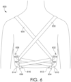
- FIG. 6 illustrates a back view of yet another support garment 600 having an example strap configuration in accordance with the claimed invention.
- the support garment 600 shares some of the features of the support garment 100 such as features associated with the front portion 110 and, as such, these same features will not be discussed in detail. Instead, differences between the support garment 600 and the support garment 100 will be highlighted.
- the support garment 600 comprises at least a first wing 610 terminating in a first terminal end 612, and a second wing 614 terminating in a second terminal end 616.
- the first wing 610 comprises a first aperture 618 and a second aperture 620.
- the second wing 614 comprises a third aperture 622 and a fourth aperture 624.
- the first, second, third, and fourth apertures 618/620/622/624 all comprise through apertures that extend through the thickness of the first and second wings 610/614 respectively.
- the first aperture 618 is located proximal to the first terminal end 612 and is further located proximal to an upper margin 632 of the first wing 610.
- the second aperture 620 is located inferior to the first aperture 618 and is further located proximal to the first terminal end 612 and proximal to a lower margin 634 of the first wing 610.
- the third aperture 622 is located proximal to the second terminal end 616 and is further located proximal to an upper margin 636 of the second wing 614.
- the fourth aperture 624 is located inferior to the third aperture 622 and is further located proximal to the second terminal end 616 and proximal to a lower margin 638 of the second wing 614.
- the support garment 600 comprises a single, continuous strap 630 having a first end (not seen in FIG. 6 ) adjustably secured to a first breast contacting surface and a second end (not seen in FIG. 6 ) adjustably secured to a second breast contacting surface.
- the strap 630 extends from its first end, passes over a wearer's shoulder and then crosses diagonally downward to pass through the third aperture 622 located on the second wing 614. The strap 630 then crosses diagonally downward between the second terminal end 616 and the first terminal end 612 to pass through the second aperture 620 located on the first wing 610.
- the strap 620 After passing through the second aperture 620, the strap 620 extends horizontally from the first terminal end 612 to the second terminal end 616 to pass through the fourth aperture 624. Continuing, the strap 630 then extends diagonally upward between the second terminal end 616 and the first terminal end 612 to pass through the first aperture 618 located on the first wing 610. After passing through the first aperture 618, the strap 630 then crosses diagonally upward, passes over the wearer's other shoulder and terminates at its second end. An adjustment of the first end of the strap 630 would be translated through the apertures 618, 620, 622, and 624 to an adjustment of the second end of the strap 630.
- the result of the strap configuration shown for the support garment 600 is similar to a corset-like lacing configuration. The use of this type of configuration may help to evenly distribute any tensioning forces applied to the strap 620.
- the different strap configurations shown for the support garments 100, 300, 400, 500, and 600 allow for the simultaneous adjustment of multiple, different support garment portions via manipulation of a single adjustment mechanism.
Landscapes
- Engineering & Computer Science (AREA)
- Textile Engineering (AREA)
- Corsets Or Brassieres (AREA)
- Details Of Garments (AREA)
- Professional, Industrial, Or Sporting Protective Garments (AREA)
Claims (8)
- Ein Stützkleidungsstück (600), umfassend:einen vorderen Abschnitt (110), umfassend mindestens einen oberen Rand (116), wobei der obere Rand (116) eine erste Befestigungsstelle (118) und eine zweite Befestigungsstelle (120) aufweist, wobei der vordere Abschnitt (110) ferner eine erste Seite (124) und eine zweite Seite (126) umfasst,einen ersten Flügel (610), der sich seitlich von der ersten Seite (124) des vorderen Abschnitts (110) weg erstreckt und in einem ersten Abschlussende (612) endet, wobei der erste Flügel (610) eine erste Öffnung (618) und eine zweite Öffnung (620) umfasst, wobei sich die erste Öffnung (618) und die zweite Öffnung (620) proximal zum ersten Abschlussende (612) befinden, wobei sich die zweite Öffnung (620) unterhalb der ersten Öffnung (618) befindet;einen zweiten Flügel (614), der sich seitlich von der zweiten Seite (126) des vorderen Abschnitts (110) weg erstreckt und in einem zweiten Abschlussende (616) endet, wobei der zweite Flügel (614) eine dritte Öffnung (622) und eine vierte Öffnung (624) umfasst, wobei die dritte Öffnung (622) und die vierte Öffnung (624) sich proximal zum zweiten Abschlussende (616) befindet, wobei sich die vierte Öffnung (624) unterhalb der dritten Öffnung (622) befindet;ein einzelner, durchgehender Riemen (128, 630) mit einem ersten Ende (130), einem zweiten Ende (134) und einem dazwischenliegenden Abschnitt (222), der sich zwischen dem ersten Ende (130) und dem zweiten Ende (134) erstreckt,dadurch gekennzeichnet, dass:das erste Ende (130) einstellbar an der ersten Befestigungsstelle (118) des vorderen Abschnitts (110) befestigt ist,das zweite Ende (134) einstellbar an der zweiten Befestigungsstelle (120) des vorderen Abschnitts (110) befestigt ist, undwobei der einzelne, durchgehende Riemen (128, 630) konfiguriert ist, um vom ersten Ende (130) auszugehen, über die Schulter eines Trägers zu verlaufen, dann diagonal nach unten zu kreuzen, um durch die dritte Öffnung (622) zu verlaufen, dann durch die zweite Öffnung (620) zu verlaufen, durch die vierte Öffnung (624) zu, dann durch die erste Öffnung (618) zu verlaufen, dann diagonal nach oben zu kreuzen, über die andere Schulter eines Trägers zu verlaufen und am zweiten Ende (134) zu enden.
- Das Stützkleidungsstück (600) nach Anspruch 1, wobei das erste Abschlussende (612) des ersten Flügels (610) nicht direkt am zweiten Abschlussende (616) des zweiten Flügels (614) befestigt ist.
- Das Stützkleidungsstück (600) nach irgendeinem der Ansprüche von 1 bis 2, wobei sich das erste Abschlussende (612) des ersten Flügels (610) auf derselben Seite des Stützkleidungsstücks (600) wie die erste Befestigungsstelle (118) befindet, und wobei sich das zweite Abschlussende (616) des zweiten Flügels (614) auf derselben Seite des Stützkleidungsstücks (600) wie die zweite Befestigungsstelle (120) befindet.
- Das Stützkleidungsstück (600) nach irgendeinem der Ansprüche von 1 bis 3, wobei sich die erste Öffnung (618) in der Nähe eines oberen Randes (632) des ersten Abschlussendes (612) befindet, und wobei sich die zweite Öffnung (620) in der Nähe eines unteren Randes (634) des ersten Abschlussendes (612) befindet.
- Das Stützkleidungsstück (600) nach irgendeinem der Ansprüche von 1 bis 4, wobei die erste Öffnung (618) und die zweite Öffnung (620) jeweils mit einem Verstärkungsmaterial umschlossen sind.
- Das Stützkleidungsstück (600) nach irgendeinem der Ansprüche von 1 bis 5, wobei sich die dritte Öffnung (622) in der Nähe eines oberen Randes (636) des zweiten Abschlussendes (616) befindet, und wobei sich die vierte Öffnung (624) in der Nähe eines unteren Randes (638) des zweiten Abschlussendes (616) befindet.
- Das Stützkleidungsstück (600) nach irgendeinem der Ansprüche von 1 bis 6, wobei der einzelne durchgehende Riemen (128) unter Verwendung eines ersten Einstellmechanismus (132) an der ersten Befestigungsstelle (118) einstellbar befestigt ist, und wobei der einzelne durchgehende Riemen (128) unter Verwendung eines zweiten Einstellmechanismus (136) an der zweiten Befestigungsstelle (120) einstellbar befestigt ist.
- Das Stützkleidungsstück (600) nach irgendeinem der Ansprüche von 1 bis 7, wobei der einzelne, durchgehende Riemen (128) aus einem elastisch federnden Material gebildet ist.
Applications Claiming Priority (4)
| Application Number | Priority Date | Filing Date | Title |
|---|---|---|---|
| US201762540376P | 2017-08-02 | 2017-08-02 | |
| US16/028,847 US10765153B2 (en) | 2017-08-02 | 2018-07-06 | Strap configuration for a support garment |
| PCT/US2018/044820 WO2019028147A1 (en) | 2017-08-02 | 2018-08-01 | STRAP CONFIGURATION FOR A SUPPORT GARMENT |
| EP18755642.8A EP3661380B1 (de) | 2017-08-02 | 2018-08-01 | Gurtkonfiguration für ein stützkleidungsstück |
Related Parent Applications (2)
| Application Number | Title | Priority Date | Filing Date |
|---|---|---|---|
| EP18755642.8A Division EP3661380B1 (de) | 2017-08-02 | 2018-08-01 | Gurtkonfiguration für ein stützkleidungsstück |
| EP18755642.8A Division-Into EP3661380B1 (de) | 2017-08-02 | 2018-08-01 | Gurtkonfiguration für ein stützkleidungsstück |
Publications (3)
| Publication Number | Publication Date |
|---|---|
| EP4309530A2 EP4309530A2 (de) | 2024-01-24 |
| EP4309530A3 EP4309530A3 (de) | 2024-04-17 |
| EP4309530B1 true EP4309530B1 (de) | 2025-05-28 |
Family
ID=65230984
Family Applications (2)
| Application Number | Title | Priority Date | Filing Date |
|---|---|---|---|
| EP18755642.8A Active EP3661380B1 (de) | 2017-08-02 | 2018-08-01 | Gurtkonfiguration für ein stützkleidungsstück |
| EP23213566.5A Active EP4309530B1 (de) | 2017-08-02 | 2018-08-01 | Gurtkonfiguration für ein stützkleidungsstück |
Family Applications Before (1)
| Application Number | Title | Priority Date | Filing Date |
|---|---|---|---|
| EP18755642.8A Active EP3661380B1 (de) | 2017-08-02 | 2018-08-01 | Gurtkonfiguration für ein stützkleidungsstück |
Country Status (5)
| Country | Link |
|---|---|
| US (2) | US10765153B2 (de) |
| EP (2) | EP3661380B1 (de) |
| CN (2) | CN115067583A (de) |
| TW (1) | TWM576397U (de) |
| WO (1) | WO2019028147A1 (de) |
Families Citing this family (17)
| Publication number | Priority date | Publication date | Assignee | Title |
|---|---|---|---|---|
| US10765153B2 (en) * | 2017-08-02 | 2020-09-08 | Nike, Inc. | Strap configuration for a support garment |
| USD865321S1 (en) * | 2018-01-26 | 2019-11-05 | Tomima Edmark | Garment adjustment feature |
| USD866118S1 (en) * | 2018-04-30 | 2019-11-12 | Spanx, Inc. | Sports bra |
| USD865324S1 (en) * | 2018-04-30 | 2019-11-05 | Spanx, Inc. | Sports bra |
| USD865323S1 (en) | 2018-04-30 | 2019-11-05 | Spanx, Inc. | Sports bra |
| EP3796799B1 (de) * | 2018-05-22 | 2024-06-26 | Shock Doctor, Inc. | Kleidungsstücke mit grösseneinstellsystemen |
| USD913631S1 (en) * | 2019-02-27 | 2021-03-23 | Hanes France Sas | Brassiere |
| US11523640B2 (en) * | 2019-09-05 | 2022-12-13 | Adidas Ag | Athletic bra |
| USD1001429S1 (en) * | 2021-03-23 | 2023-10-17 | Lululemon Athletica Canada Inc. | Garment |
| US11666104B2 (en) * | 2021-11-04 | 2023-06-06 | Carla Flores | Brassiere with dual-use bra straps |
| USD980581S1 (en) * | 2022-09-01 | 2023-03-14 | Junrong Zhou | Bra |
| USD1030212S1 (en) * | 2023-08-27 | 2024-06-11 | Yongguang Cai | Underwear |
| USD1030211S1 (en) * | 2023-08-27 | 2024-06-11 | Yongguang Cai | Underwear |
| USD1030215S1 (en) * | 2023-08-30 | 2024-06-11 | Yongguang Cai | Underwear |
| USD1030214S1 (en) * | 2023-08-30 | 2024-06-11 | Yongguang Cai | Underwear |
| USD1030213S1 (en) * | 2023-08-30 | 2024-06-11 | Yongguang Cai | Underwear |
| USD1079194S1 (en) * | 2024-12-10 | 2025-06-17 | Yongguang Cai | Bra |
Family Cites Families (45)
| Publication number | Priority date | Publication date | Assignee | Title |
|---|---|---|---|---|
| GB364931A (en) | 1931-03-13 | 1932-01-14 | Forma Company Ltd | Improvements in or relating to brassieres and similar garments |
| US1926078A (en) | 1932-08-03 | 1933-09-12 | H W Gossard Co | Brassiere |
| GB424143A (en) | 1933-12-14 | 1935-02-15 | Domen Belts Company Ltd | Improvements in abdominal belts and the like |
| NL42324C (de) * | 1934-04-11 | |||
| GB476196A (en) * | 1936-08-13 | 1937-12-03 | Evelyn Wilkins | Improvements in or relating to brassieres |
| US2581036A (en) * | 1947-11-06 | 1952-01-01 | Mcilhinney Evelyn | Brassiere |
| US2521373A (en) * | 1947-12-31 | 1950-09-05 | Eleanore L Hutchison | Brassiere |
| US3935865A (en) * | 1974-11-22 | 1976-02-03 | Julie Newmar | Brassiere |
| US4300568A (en) * | 1979-05-25 | 1981-11-17 | Charles Blanckmeister | Therapeutic bra |
| US4276884A (en) | 1979-09-24 | 1981-07-07 | Daniels Avis K O | Brassiere |
| JPH0421766Y2 (de) | 1989-03-06 | 1992-05-19 | ||
| US5149293A (en) | 1991-11-29 | 1992-09-22 | Lisa Gable | Brassiere accessory |
| US5634891A (en) | 1995-04-14 | 1997-06-03 | Peach, U.S., Inc. | Orthotic apparatus useful for treating pain associated with spinal disorders |
| JPH09296307A (ja) | 1996-05-01 | 1997-11-18 | Mitsuaki Arita | 補整用ブラジャー |
| US6110007A (en) | 1999-02-03 | 2000-08-29 | Rittmann; Jean V. | T-back breast support system garment |
| US6431947B1 (en) * | 2000-07-14 | 2002-08-13 | Michael J. Henz | Fall-away brassiere |
| US6302761B1 (en) * | 2000-09-11 | 2001-10-16 | Lydia Hay Wrenn | Brassiere |
| US6547636B1 (en) * | 2000-10-11 | 2003-04-15 | Elaine A. Cato | Convertible brassiere |
| CA2429494C (en) | 2000-11-14 | 2007-08-28 | Bio Cybernetics International | Orthotic trauma device |
| FR2863834B1 (fr) | 2003-12-19 | 2006-05-05 | Euralis | Dispositif de reglage d'un soutien-gorge |
| FR2880244B1 (fr) | 2005-01-04 | 2007-04-20 | Serge Girau | Bretelle pour soutien-gorge attachee ou detachable entre ou sur les deux bonnets. |
| US20080299870A1 (en) | 2007-05-31 | 2008-12-04 | Elisabeth Penunuri | Adjustable strap for brassiere having shoulder and body engaging means |
| FR2926007A1 (fr) * | 2008-01-04 | 2009-07-10 | Dbapparel Operations Soc Par A | Soutien-gorge reglable, notamment de sport . |
| TWM342756U (en) | 2008-04-28 | 2008-10-21 | Esoniee Internat Co Ltd | Bra adjustment structure |
| GB2472259A (en) | 2009-07-31 | 2011-02-02 | Laser Optical Engineering Ltd | Brassiere |
| GB2472260B (en) * | 2009-07-31 | 2014-02-12 | Laser Optical Engineering Ltd | A brassiere |
| US20110081827A1 (en) | 2009-10-03 | 2011-04-07 | Williams R A | Gravity Bra |
| US20110117818A1 (en) | 2009-11-18 | 2011-05-19 | Patagonia, Inc. | Wrap around sports bra with support |
| US8808213B2 (en) | 2010-05-28 | 2014-08-19 | Hendricks Orthotic Prosthetic Enterprises, Inc. | Mechanically advantaged spinal system and method |
| US20130203319A1 (en) | 2011-04-13 | 2013-08-08 | Jesus Torres | Sports bra |
| FR2983684B1 (fr) | 2011-12-09 | 2014-02-07 | Decathlon Sa | Soutien gorge facile a passer, oter et regler |
| CN202489195U (zh) * | 2012-02-09 | 2012-10-17 | 浙江朗姿实业有限公司 | 一种胸罩 |
| US9408420B2 (en) | 2013-09-19 | 2016-08-09 | Catherine Anne Betts | Adjustable bra |
| JP5639290B1 (ja) * | 2014-01-06 | 2014-12-10 | 喜英子 柴▲崎▼ | カップ部を有する衣類 |
| CN204273281U (zh) | 2014-08-01 | 2015-04-22 | 邝斌 | 一种松紧度可调式隐形内衣 |
| US9700082B2 (en) | 2014-09-16 | 2017-07-11 | Nike, Inc. | Wrap front bra |
| US9462833B1 (en) * | 2014-10-14 | 2016-10-11 | Bali Kini Co. | Interchangeable and adjustable bikini attachment and closure system |
| FR3027194B1 (fr) | 2014-10-17 | 2017-07-28 | Dbapparel Operations | Soutien-gorge adapte pour la pratique sportive |
| US9743693B2 (en) * | 2015-01-19 | 2017-08-29 | Caryn Zambelli | Cover and method for covering part of an undergarment |
| US9615616B2 (en) | 2015-03-24 | 2017-04-11 | Golda, Inc. | Surgical convertible bra |
| WO2016175804A1 (en) | 2015-04-29 | 2016-11-03 | North Carolina State University | Adjustable bra |
| WO2017015452A1 (en) | 2015-07-23 | 2017-01-26 | Debra Abbaszadeh | Pumping/nursing bra |
| US20170055602A1 (en) | 2015-08-25 | 2017-03-02 | Carl J. Abraham | Breast protective garment |
| US20180325185A1 (en) * | 2017-05-10 | 2018-11-15 | Mia Sakai | Convertible Brassiere System With Interchangeable Components |
| US10765153B2 (en) | 2017-08-02 | 2020-09-08 | Nike, Inc. | Strap configuration for a support garment |
-
2018
- 2018-07-06 US US16/028,847 patent/US10765153B2/en active Active
- 2018-08-01 CN CN202210610245.0A patent/CN115067583A/zh active Pending
- 2018-08-01 WO PCT/US2018/044820 patent/WO2019028147A1/en not_active Ceased
- 2018-08-01 CN CN201880047031.9A patent/CN110891447B/zh active Active
- 2018-08-01 TW TW107210502U patent/TWM576397U/zh unknown
- 2018-08-01 EP EP18755642.8A patent/EP3661380B1/de active Active
- 2018-08-01 EP EP23213566.5A patent/EP4309530B1/de active Active
-
2020
- 2020-07-30 US US16/943,066 patent/US11877603B2/en active Active
Also Published As
| Publication number | Publication date |
|---|---|
| WO2019028147A1 (en) | 2019-02-07 |
| US10765153B2 (en) | 2020-09-08 |
| EP3661380A1 (de) | 2020-06-10 |
| TWM576397U (zh) | 2019-04-11 |
| US20200352257A1 (en) | 2020-11-12 |
| EP4309530A3 (de) | 2024-04-17 |
| CN110891447A (zh) | 2020-03-17 |
| US20190037930A1 (en) | 2019-02-07 |
| CN110891447B (zh) | 2022-05-24 |
| US11877603B2 (en) | 2024-01-23 |
| CN115067583A (zh) | 2022-09-20 |
| EP3661380B1 (de) | 2024-08-14 |
| EP4309530A2 (de) | 2024-01-24 |
Similar Documents
| Publication | Publication Date | Title |
|---|---|---|
| EP4309530B1 (de) | Gurtkonfiguration für ein stützkleidungsstück | |
| US9918500B2 (en) | Wrap front bra | |
| US6173449B1 (en) | One-piece women's sunbathing beach and swim suit | |
| US7448937B2 (en) | Cleavage-enhancing foundation garment | |
| US7056186B1 (en) | Cleavage-enhancing foundation garment | |
| US20200288791A1 (en) | Adjustable breast support garment | |
| US10709175B2 (en) | Bra and garment with bra portion | |
| US12232546B2 (en) | Bra with intermediary flexible layer and method for manufacturing same | |
| US20160000154A1 (en) | Anti-Wrinkle Bra for Sleeping | |
| HK40021228A (en) | Strap configuration for a support garment | |
| HK40021228B (en) | Strap configuration for a support garment | |
| US11344068B2 (en) | Bandless brassiere | |
| KR101271907B1 (ko) | 브래지어 | |
| WO2021015178A1 (ja) | カップ部を有する衣類 |
Legal Events
| Date | Code | Title | Description |
|---|---|---|---|
| PUAI | Public reference made under article 153(3) epc to a published international application that has entered the european phase |
Free format text: ORIGINAL CODE: 0009012 |
|
| STAA | Information on the status of an ep patent application or granted ep patent |
Free format text: STATUS: THE APPLICATION HAS BEEN PUBLISHED |
|
| AC | Divisional application: reference to earlier application |
Ref document number: 3661380 Country of ref document: EP Kind code of ref document: P |
|
| AK | Designated contracting states |
Kind code of ref document: A2 Designated state(s): AL AT BE BG CH CY CZ DE DK EE ES FI FR GB GR HR HU IE IS IT LI LT LU LV MC MK MT NL NO PL PT RO RS SE SI SK SM TR |
|
| PUAL | Search report despatched |
Free format text: ORIGINAL CODE: 0009013 |
|
| AK | Designated contracting states |
Kind code of ref document: A3 Designated state(s): AL AT BE BG CH CY CZ DE DK EE ES FI FR GB GR HR HU IE IS IT LI LT LU LV MC MK MT NL NO PL PT RO RS SE SI SK SM TR |
|
| RIC1 | Information provided on ipc code assigned before grant |
Ipc: A41F 15/00 20060101ALI20240314BHEP Ipc: A41C 3/00 20060101AFI20240314BHEP |
|
| P01 | Opt-out of the competence of the unified patent court (upc) registered |
Effective date: 20240522 |
|
| STAA | Information on the status of an ep patent application or granted ep patent |
Free format text: STATUS: REQUEST FOR EXAMINATION WAS MADE |
|
| 17P | Request for examination filed |
Effective date: 20241010 |
|
| RBV | Designated contracting states (corrected) |
Designated state(s): AL AT BE BG CH CY CZ DE DK EE ES FI FR GB GR HR HU IE IS IT LI LT LU LV MC MK MT NL NO PL PT RO RS SE SI SK SM TR |
|
| GRAP | Despatch of communication of intention to grant a patent |
Free format text: ORIGINAL CODE: EPIDOSNIGR1 |
|
| STAA | Information on the status of an ep patent application or granted ep patent |
Free format text: STATUS: GRANT OF PATENT IS INTENDED |
|
| INTG | Intention to grant announced |
Effective date: 20241220 |
|
| GRAS | Grant fee paid |
Free format text: ORIGINAL CODE: EPIDOSNIGR3 |
|
| GRAA | (expected) grant |
Free format text: ORIGINAL CODE: 0009210 |
|
| STAA | Information on the status of an ep patent application or granted ep patent |
Free format text: STATUS: THE PATENT HAS BEEN GRANTED |
|
| AC | Divisional application: reference to earlier application |
Ref document number: 3661380 Country of ref document: EP Kind code of ref document: P |
|
| AK | Designated contracting states |
Kind code of ref document: B1 Designated state(s): AL AT BE BG CH CY CZ DE DK EE ES FI FR GB GR HR HU IE IS IT LI LT LU LV MC MK MT NL NO PL PT RO RS SE SI SK SM TR |
|
| REG | Reference to a national code |
Ref country code: GB Ref legal event code: FG4D |
|
| REG | Reference to a national code |
Ref country code: CH Ref legal event code: EP |
|
| REG | Reference to a national code |
Ref country code: DE Ref legal event code: R096 Ref document number: 602018082347 Country of ref document: DE |
|
| REG | Reference to a national code |
Ref country code: IE Ref legal event code: FG4D |
|
| PGFP | Annual fee paid to national office [announced via postgrant information from national office to epo] |
Ref country code: GB Payment date: 20250612 Year of fee payment: 8 |
|
| PGFP | Annual fee paid to national office [announced via postgrant information from national office to epo] |
Ref country code: FR Payment date: 20250610 Year of fee payment: 8 |
|
| REG | Reference to a national code |
Ref country code: NL Ref legal event code: MP Effective date: 20250528 |
|
| PG25 | Lapsed in a contracting state [announced via postgrant information from national office to epo] |
Ref country code: FI Free format text: LAPSE BECAUSE OF FAILURE TO SUBMIT A TRANSLATION OF THE DESCRIPTION OR TO PAY THE FEE WITHIN THE PRESCRIBED TIME-LIMIT Effective date: 20250528 Ref country code: ES Free format text: LAPSE BECAUSE OF FAILURE TO SUBMIT A TRANSLATION OF THE DESCRIPTION OR TO PAY THE FEE WITHIN THE PRESCRIBED TIME-LIMIT Effective date: 20250528 |
|
| PGFP | Annual fee paid to national office [announced via postgrant information from national office to epo] |
Ref country code: DE Payment date: 20250604 Year of fee payment: 8 |
|
| REG | Reference to a national code |
Ref country code: LT Ref legal event code: MG9D |
|
| PG25 | Lapsed in a contracting state [announced via postgrant information from national office to epo] |
Ref country code: NO Free format text: LAPSE BECAUSE OF FAILURE TO SUBMIT A TRANSLATION OF THE DESCRIPTION OR TO PAY THE FEE WITHIN THE PRESCRIBED TIME-LIMIT Effective date: 20250828 Ref country code: GR Free format text: LAPSE BECAUSE OF FAILURE TO SUBMIT A TRANSLATION OF THE DESCRIPTION OR TO PAY THE FEE WITHIN THE PRESCRIBED TIME-LIMIT Effective date: 20250829 |
|
| PG25 | Lapsed in a contracting state [announced via postgrant information from national office to epo] |
Ref country code: NL Free format text: LAPSE BECAUSE OF FAILURE TO SUBMIT A TRANSLATION OF THE DESCRIPTION OR TO PAY THE FEE WITHIN THE PRESCRIBED TIME-LIMIT Effective date: 20250528 Ref country code: PL Free format text: LAPSE BECAUSE OF FAILURE TO SUBMIT A TRANSLATION OF THE DESCRIPTION OR TO PAY THE FEE WITHIN THE PRESCRIBED TIME-LIMIT Effective date: 20250528 |
|
| PG25 | Lapsed in a contracting state [announced via postgrant information from national office to epo] |
Ref country code: BG Free format text: LAPSE BECAUSE OF FAILURE TO SUBMIT A TRANSLATION OF THE DESCRIPTION OR TO PAY THE FEE WITHIN THE PRESCRIBED TIME-LIMIT Effective date: 20250528 |
|
| PG25 | Lapsed in a contracting state [announced via postgrant information from national office to epo] |
Ref country code: HR Free format text: LAPSE BECAUSE OF FAILURE TO SUBMIT A TRANSLATION OF THE DESCRIPTION OR TO PAY THE FEE WITHIN THE PRESCRIBED TIME-LIMIT Effective date: 20250528 |
|
| PG25 | Lapsed in a contracting state [announced via postgrant information from national office to epo] |
Ref country code: RS Free format text: LAPSE BECAUSE OF FAILURE TO SUBMIT A TRANSLATION OF THE DESCRIPTION OR TO PAY THE FEE WITHIN THE PRESCRIBED TIME-LIMIT Effective date: 20250828 |
|
| PG25 | Lapsed in a contracting state [announced via postgrant information from national office to epo] |
Ref country code: IS Free format text: LAPSE BECAUSE OF FAILURE TO SUBMIT A TRANSLATION OF THE DESCRIPTION OR TO PAY THE FEE WITHIN THE PRESCRIBED TIME-LIMIT Effective date: 20250928 |
|
| PG25 | Lapsed in a contracting state [announced via postgrant information from national office to epo] |
Ref country code: LV Free format text: LAPSE BECAUSE OF FAILURE TO SUBMIT A TRANSLATION OF THE DESCRIPTION OR TO PAY THE FEE WITHIN THE PRESCRIBED TIME-LIMIT Effective date: 20250528 |
|
| REG | Reference to a national code |
Ref country code: AT Ref legal event code: MK05 Ref document number: 1798103 Country of ref document: AT Kind code of ref document: T Effective date: 20250528 |
|
| PG25 | Lapsed in a contracting state [announced via postgrant information from national office to epo] |
Ref country code: SM Free format text: LAPSE BECAUSE OF FAILURE TO SUBMIT A TRANSLATION OF THE DESCRIPTION OR TO PAY THE FEE WITHIN THE PRESCRIBED TIME-LIMIT Effective date: 20250528 Ref country code: AT Free format text: LAPSE BECAUSE OF FAILURE TO SUBMIT A TRANSLATION OF THE DESCRIPTION OR TO PAY THE FEE WITHIN THE PRESCRIBED TIME-LIMIT Effective date: 20250528 Ref country code: DK Free format text: LAPSE BECAUSE OF FAILURE TO SUBMIT A TRANSLATION OF THE DESCRIPTION OR TO PAY THE FEE WITHIN THE PRESCRIBED TIME-LIMIT Effective date: 20250528 |
|
| PG25 | Lapsed in a contracting state [announced via postgrant information from national office to epo] |
Ref country code: CZ Free format text: LAPSE BECAUSE OF FAILURE TO SUBMIT A TRANSLATION OF THE DESCRIPTION OR TO PAY THE FEE WITHIN THE PRESCRIBED TIME-LIMIT Effective date: 20250528 |
|
| PG25 | Lapsed in a contracting state [announced via postgrant information from national office to epo] |
Ref country code: EE Free format text: LAPSE BECAUSE OF FAILURE TO SUBMIT A TRANSLATION OF THE DESCRIPTION OR TO PAY THE FEE WITHIN THE PRESCRIBED TIME-LIMIT Effective date: 20250528 |
|
| PG25 | Lapsed in a contracting state [announced via postgrant information from national office to epo] |
Ref country code: SK Free format text: LAPSE BECAUSE OF FAILURE TO SUBMIT A TRANSLATION OF THE DESCRIPTION OR TO PAY THE FEE WITHIN THE PRESCRIBED TIME-LIMIT Effective date: 20250528 |
|
| PG25 | Lapsed in a contracting state [announced via postgrant information from national office to epo] |
Ref country code: IT Free format text: LAPSE BECAUSE OF FAILURE TO SUBMIT A TRANSLATION OF THE DESCRIPTION OR TO PAY THE FEE WITHIN THE PRESCRIBED TIME-LIMIT Effective date: 20250528 |
|
| PG25 | Lapsed in a contracting state [announced via postgrant information from national office to epo] |
Ref country code: RO Free format text: LAPSE BECAUSE OF FAILURE TO SUBMIT A TRANSLATION OF THE DESCRIPTION OR TO PAY THE FEE WITHIN THE PRESCRIBED TIME-LIMIT Effective date: 20250528 |
|
| REG | Reference to a national code |
Ref country code: CH Ref legal event code: H13 Free format text: ST27 STATUS EVENT CODE: U-0-0-H10-H13 (AS PROVIDED BY THE NATIONAL OFFICE) Effective date: 20260324 |