EP4309396B1 - Reinigung hängender legaler abhörressourcen von einem ausgelösten abhörpunkt bei ausfall einer auslösefunktion - Google Patents
Reinigung hängender legaler abhörressourcen von einem ausgelösten abhörpunkt bei ausfall einer auslösefunktion Download PDFInfo
- Publication number
- EP4309396B1 EP4309396B1 EP22710897.4A EP22710897A EP4309396B1 EP 4309396 B1 EP4309396 B1 EP 4309396B1 EP 22710897 A EP22710897 A EP 22710897A EP 4309396 B1 EP4309396 B1 EP 4309396B1
- Authority
- EP
- European Patent Office
- Prior art keywords
- smf
- triggering
- function
- request
- failed
- Prior art date
- Legal status (The legal status is an assumption and is not a legal conclusion. Google has not performed a legal analysis and makes no representation as to the accuracy of the status listed.)
- Active
Links
Images


Classifications
-
- H—ELECTRICITY
- H04—ELECTRIC COMMUNICATION TECHNIQUE
- H04W—WIRELESS COMMUNICATION NETWORKS
- H04W12/00—Security arrangements; Authentication; Protecting privacy or anonymity
- H04W12/80—Arrangements enabling lawful interception [LI]
-
- H—ELECTRICITY
- H04—ELECTRIC COMMUNICATION TECHNIQUE
- H04L—TRANSMISSION OF DIGITAL INFORMATION, e.g. TELEGRAPHIC COMMUNICATION
- H04L63/00—Network architectures or network communication protocols for network security
- H04L63/30—Network architectures or network communication protocols for network security for supporting lawful interception, monitoring or retaining of communications or communication related information
- H04L63/306—Network architectures or network communication protocols for network security for supporting lawful interception, monitoring or retaining of communications or communication related information intercepting packet switched data communications, e.g. Web, Internet or IMS communications
-
- H—ELECTRICITY
- H04—ELECTRIC COMMUNICATION TECHNIQUE
- H04W—WIRELESS COMMUNICATION NETWORKS
- H04W84/00—Network topologies
- H04W84/02—Hierarchically pre-organised networks, e.g. paging networks, cellular networks, WLAN [Wireless Local Area Network] or WLL [Wireless Local Loop]
- H04W84/04—Large scale networks; Deep hierarchical networks
- H04W84/042—Public Land Mobile systems, e.g. cellular systems
Definitions
- Wireless communication systems are widely deployed to provide various types of communication content such as voice, video, data, and so on. These systems may be multiple-access systems capable of supporting simultaneous communication of one or more wireless communication devices.
- a wireless multiple-access communications system may include a number of base stations or network access nodes, each simultaneously supporting communication for multiple communication devices, which may be known as user equipment (UE).
- UE user equipment
- 4G Long Term Evolution
- LTE-A LTE-Advanced
- LTE-A Pro LTE-A Pro
- 5G wireless communication systems are already being deployed and are expected to become widespread in the near future.
- the industry consortium setting standards for 5G is the 3rd Generation Partnership Project (3GPP).
- 5G systems will have greater bandwidth, thereby providing faster download speeds. Due to the increased bandwidth, it is expected that 5G systems will facilitate many new applications in areas of technology such as Internet of Things (IoT) devices and machine-to-machine communication.
- IoT Internet of Things
- the 5G system architecture is significantly different from its predecessors in many respects.
- network management can be software driven, and network functions and resources can be virtualized at the edges and inside the network core.
- a 5G system implementation can be based on cloud-native applications, virtualized network functions, and microservices-based design patterns.
- a 5G system implementation can provide support for stateless network functions by decoupling compute and storage.
- LI Lawful interception
- 3GPP TS 33.127 defines an LI architecture for 5G systems. Among other things, this LI architecture defines how network operators and law enforcement agents can interact.
- the LI architecture set forth in 3GPP TS 33.127 includes the following aspects: collection where target-related data and content are extracted from the network, mediation where the data is formatted to conform to specific standards, and delivery of the data and content to the law enforcement agency.
- LTE Long Term Evolution
- 5G Digital cellular telecommunications system (Phase 2+) (GSM); Universal Mobile Telecommunications System (UMTS); Lawful Interception architecture and functions (3GPP TS 33.127 version 16.5.0 Release 16)", ETSI Technical Specification, European Telecommunications Standards Institute, 650, Route des Lucioles; F-06921 SOPHIA-ANTIPOLIS; France, vol. 3GPP SA, no. V16.5.0 5 November 2020 .
- One aspect of the present disclosure is a method for enabling hanging lawful interception (LI) resources to be cleaned up in a mobile network that comprises a triggering function set and a data store.
- the triggering function set comprises a plurality of triggering functions.
- the data store comprises a plurality of auditing records corresponding to the plurality of triggering functions.
- the method comprises causing each triggering function among the plurality of triggering functions to send an update request to the data store in response to being notified about a failed triggering function within the triggering function set.
- Each update request comprises a request to change ownership of an auditing record corresponding to the failed triggering function.
- the method also comprises selecting a triggering function as a new owner of the auditing record corresponding to the failed triggering function based at least in part on a match between a claimant attribute in the auditing record and a claimant field in the update request sent by the triggering function.
- the method also comprises causing the new owner of the auditing record corresponding to the failed triggering function to send at least one request to a triggered point of interception (POI) to remove an LI resource corresponding to the failed triggering function.
- POI triggered point of interception
- each update request can comprise the claimant field that identifies the failed triggering function and a request to modify the claimant attribute of the auditing record to an identifier associated with a sender of the update request.
- the failed triggering function can comprise a failed session management function (SMF) and the plurality of triggering functions can comprise a plurality of SMFs.
- SMF session management function
- the data store can comprise an unstructured data storage network function (UDSF).
- UDSF unstructured data storage network function
- the triggered POI can reside within a user plane function (UPF).
- UPF user plane function
- the method can additionally comprise notifying the plurality of triggering functions in the triggering function set about the failed triggering function.
- the method can additionally comprise causing each triggering function among the plurality of triggering functions to register with a network function repository function.
- the at least one request that is sent to the triggered POI can comprise a first request to deactivate all tasks associated with the failed triggering function, and a second request to remove all destinations associated with the failed triggering function.
- the method can additionally comprise causing the new owner of the auditing record corresponding to the failed triggering function to send a request to the data store to remove the auditing record from the data store.
- Another aspect of the present disclosure is directed to a method for enabling hanging lawful interception (LI) resources to be cleaned up.
- the method is implemented by a triggering function that belongs to a triggering function set that comprises a plurality of triggering functions.
- the method comprises receiving notification about a failed triggering function in the triggering function set.
- the method also comprises sending, in response to the notification, an update request to a data store that comprises a plurality of auditing records corresponding to the plurality of triggering functions.
- the update request comprises a request to change ownership of an auditing record corresponding to the failed triggering function.
- the method also comprises receiving, in response to sending the update request, an indication that the triggering function has been selected as a new owner of the auditing record based at least in part on a match between a claimant attribute in the auditing record and a claimant field in the update request sent by the triggering function.
- the method also comprises sending, in response to receiving the indication, at least one request to a triggered point of interception (POI) to remove an LI resource corresponding to the failed triggering function.
- POI point of interception
- the claimant field can identify the failed triggering function
- the update request can comprise a request to modify the claimant attribute of the auditing record to an identifier associated with the triggering function.
- the triggering function can comprise a session management function (SMF)
- the failed triggering function can comprise a failed SMF
- the plurality of triggering functions can comprise a plurality of SMFs.
- the data store can comprise an unstructured data storage network function (UDSF).
- UDSF unstructured data storage network function
- the triggered POI can reside within a user plane function (UPF).
- UPF user plane function
- the method can further comprise registering with a network function repository function (NRF).
- NRF network function repository function
- the at least one request that is sent to the triggered POI can comprise a first request to deactivate all tasks associated with the failed triggering function and a second request to remove all destinations associated with the failed triggering function.
- the method can additionally comprise sending a request to the data store to remove the auditing record from the data store.
- the system includes one or more processors and memory in electronic communication with the one or more processors.
- a triggering function set is stored in the memory.
- the triggering function set comprises a plurality of triggering functions.
- a data store is also provided in the memory.
- the data store comprises a plurality of auditing records corresponding to the plurality of triggering functions in the triggering function set. Each auditing record comprises a claimant attribute.
- Instructions are stored in the memory. The instructions are executable by the one or more processors to cause each triggering function among the plurality of triggering functions to send an update request to the data store in response to being notified about a failed triggering function within the triggering function set.
- Each update request comprises a request to change ownership of the auditing record corresponding to the failed triggering function.
- the instructions are also executable by the one or more processors to select a triggering function as a new owner of the auditing record corresponding to the failed triggering function based at least in part on a match between the claimant attribute in the auditing record and a claimant field in the update request sent by the triggering function.
- the instructions are also executable by the one or more processors to cause the new owner of the auditing record corresponding to the failed triggering function to send at least one request to a triggered point of interception (POI) to remove an LI resource corresponding to the failed triggering function.
- POI triggered point of interception
- each update request can comprise the claimant field that identifies the failed triggering function and a request to modify the claimant attribute of the auditing record to an identifier associated with a sender of the update request.
- the system can be configured such that the request to modify the claimant attribute is only granted when the claimant field matches the claimant attribute of the auditing record.
- the present disclosure is generally related to cleaning up hanging lawful interception (LI) resources from a triggered point of interception (POI) when a triggering function fails.
- LI lawful interception
- POI point of interception
- triggering is defined as the action taken by a dedicated function (which is referred to as a "triggering function”) to provide another dedicated function (which is referred to as a "triggered POI") that provisioning could not directly be applied to, with information that identifies the specific target communication to be intercepted.
- 3GPP TS 33.127 describes a scenario in which a session management function (SMF) is responsible for creating and removing LI resources on a user plane function (UPF).
- SMF session management function
- UPF user plane function
- the SMF can be considered to be a triggering function
- the triggered POI resides on the UPF.
- the systems and methods disclosed herein will be described in relation to this scenario. However, the scope of the present disclosure is not limited in this regard. The systems and methods disclosed herein are applicable to other scenarios involving other triggering functions and/or other triggered POIs.
- the LI resources disclosed herein can include tasks and destinations.
- the term "task” can refer to the entity whose network data is being intercepted.
- a task can be an individual subscriber, a mobile number, an IP address, etc.
- destination can refer to the place(s) where the intercepted data should be sent.
- an SMF can fail and experience unplanned downtime after provisioning. There are many reasons why an SMF can fail. For example, an SMF can fail because of a hardware failure. If an SMF fails after provisioning, then the UPF LI resources can remain hanging because the SMF is no longer available in the network.
- the current solution to this problem is to clean up hanging resources based on inactivity. More specifically, if there is no activity on the part of the SMF for a certain period of time (which can be referred to as "Time-P2”), then the hanging resources will be cleaned up (e.g., deleted).
- Time-P2 a certain period of time
- the default value of Time-P2 is one hour, which means that under the current approach resources typically continue intercepting user data for a relatively long period of time. However, if any intercept warrant has expired or been revoked in the Time-P2 time period, then it is illegal to continue intercepting user data.
- Another disadvantage with the current approach is that if the SMF comes up again and sends any message to the UPF before the expiration of the Time-P2 time period, then the hanging resources will not be cleaned up.
- the present disclosure proposes an auditing mechanism to take ownership of the failed SMF in order to clean up hanging resources on the UPF.
- the auditing mechanism disclosed herein takes advantage of the 3GPP concept of a set of SMFs. This may alternatively be referred to as creating a pool of SMFs. For consistency, the term "set" will be used in the discussion that follows.
- each SMF can be configured with the network element identifier (NEID) as well as the network function (NF) instance ID of all other SMFs in the set.
- NEID network element identifier
- NF network function
- Each SMF in a particular SMF set maintains its NEID-related record in a data store that is accessible to every SMF in the SMF set.
- the data store can be an unstructured data storage network function (UDSF).
- UDSF unstructured data storage network function
- the record corresponding to a particular SMF contains a claimant attribute that identifies the SMF as the owner of the record.
- Each SMF in the SMF set receives updates about the liveliness of other SMFs.
- the updates can be received from the network function repository function (NRF) via the Nnrf interface.
- NRF network function repository function
- all other SMFs in the SMF set are notified (e.g., by the NRF) about the status of the SMF that has failed.
- one of the active SMFs in the SMF set is expected to take ownership of the record corresponding to the failed SMF.
- each SMF in the SMF set attempts to take ownership of the record with a conditional update.
- conditional update refers to a process whereby a record (including the claimant attribute) is permitted to be modified only if the claimant attribute that is present in the record matches the claimant field that is present in the query of an update request.
- each SMF in the SMF set attempts to update the record of the failed SMF with the NEID of the failed SMF as the claimant field in the query and their own NEID as the claimant attribute in the update record. Only one of the SMFs will succeed and take ownership, and all other SMFs fail. The SMF that is successfully able to update the record is the new owner.
- the new owner then cleans up the hanging resources corresponding to the failed SMF.
- the new owner sends a DeactivateAllTasksRequest to each UPF to remove hanging tasks and waits for DeactivateAllTasksResponse.
- the new owner sends a RemoveAllDestinationsRequest to each UPF to remove hanging destinations and waits for a RemoveAllDestinationsResponse.
- the new owner also removes the record of the failed SMF.
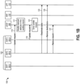
- Figures 1A and 1B illustrate an example of a method 100 for cleaning up hanging LI resources when an SMF fails.
- the entities that are involved in performing the method 100 include an SMF set 102 that includes a first SMF 102-1, a second SMF 102-2, and a third SMF 102-3.
- Other entities that are involved in performing the method 100 include a UDSF 108, an NRF 110, and a UPF 112.
- act 103 of the method 100 each of the SMFs in the SMF set 102 creates an auditing record in the UDSF 108. More specifically, act 103 of the method 100 includes act 103-1 in which the first SMF 102-1 creates a first auditing record 116-1, act 103-2 in which the second SMF 102-2 creates a second auditing record 116-2, and act 103-3 in which the third SMF 102-3 creates a third auditing record 116-3. Aspects of the auditing records 116-1, 116-2, 116-3 that are created are shown in Figure 1C .
- the first SMF 102-1 creates a first auditing record 116-1 in the UDSF 108.
- the claimant attribute 118-1 of the first auditing record 116-1 is set to an identifier corresponding to the first SMF 102-1 (e.g., NEID1).
- the second SMF 102-2 creates a second auditing record 116-2 in the UDSF 108.
- the claimant attribute 118-2 of the second auditing record 116-2 is set to an identifier corresponding to the second SMF 102-2 (e.g., NEID2).
- the third SMF 102-3 creates a third auditing record 116-3 in the UDSF 108.
- the claimant attribute 118-3 of the third auditing record 116-3 is set to an identifier corresponding to the third SMF 102-3 (e.g., NEID3).
- each of the SMFs in the SMF set 102 registers with the NRF 110 in act 105 of the method 100. More specifically, act 105 of the method 100 includes act 105-1 performed by the first SMF 102-1 and the NRF 110, act 105-2 performed by the second SMF 102-2 and the NRF 110, and act 105-3 performed by the third SMF 102-3 and the NRF 110.
- act 105-1 the first SMF 102-1 registers with the NRF 110.
- the first SMF 102-1 provides the NRF 110 with an identifier (e.g., UUID1) corresponding to the first SMF 102-1.
- act 105-2 the second SMF 102-2 registers with the NRF 110.
- the second SMF 102-2 provides the NRF 110 with an identifier (e.g., UUID2) corresponding to the second SMF 102-2.
- the third SMF 102-3 registers with the NRF 110.
- the third SMF 102-3 provides the NRF 110 with an identifier (e.g., UUID3) corresponding to the third SMF 102-3.
- act 107 of the method 100 LI tasks and LI destinations are provisioned on all of the SMFs in the SMF set 102.
- act 109 of the method 100 the first SMF 102-1 experiences a failure and becomes unavailable.
- act 111 of the method 100 the NRF 110 detects the failure of the first SMF 102-1.
- act 113 of the method 100 the NRF 110 notifies the other SMFs in the SMF set 102 that the first SMF 102-1 has failed. More specifically, act 113 of the method 100 includes acts 113-1 and 113-2.
- act 113-1 the NRF 110 notifies the second SMF 102-2 about the failure of the first SMF 102-1.
- act 113-2 the NRF 110 notifies the third SMF 102-3 about the failure of the first SMF 102-1.
- an audit mechanism is performed to see who will become the new owner of the first auditing record 116-1 corresponding to the first SMF 102-1.
- an audit mechanism is performed to see who will become the new owner of the first auditing record 116-1 corresponding to the first SMF 102-1.
- only one SMF in the SMF set 102 will be able to become the new owner of the first auditing record 116-1 corresponding to the first SMF 102-1.
- the new owner will then be responsible for the cleanup of hanging LI resources corresponding to the first SMF 102-1.
- every SMF in the SMF set 102 tries to update the first auditing record 116-1 corresponding to the first SMF 102-1 with the NEID of the first SMF 102-1 (NEID1) as the claimant field in the query and their own NEID as the claimant attribute in the update record.
- the UDSF 108 is configured so that it only permits an auditing record to be modified if the claimant attribute present in the auditing record matches the claimant field present in the query of the update request.
- the second SMF 102-2 sends an update request 120-1 to the UDSF 108.
- the update request 120-1 which is shown in Figure 1D , is a request to update the claimant attribute 118-1 of the first auditing record 116-1, which (as noted above) corresponds to the first SMF 102-1.
- the update request 120-1 includes a claimant field 122-1 and an update record 124-1.
- the update record 124-1 includes a claimant attribute 126-1.
- the value of the claimant field 122-1 is the NEID of the first SMF 102-1 (NEID1).
- the UDSF 108 grants the update request 120-1. Therefore, referring to both Figure 1B and Figure 1D , in act 117 of the method 100 the UDSF 108 modifies the claimant attribute 118-1 in the first auditing record 116-1 to the value of the claimant attribute 126-1 in the update record 124-1 of the update request 120-1 (namely, NEID2 in this example).
- the third SMF 102-3 sends another update request 120-2 to the UDSF 108.
- the update request 120-2 which is shown in Figure 1E , is another request to update the claimant attribute 118-1 of the first auditing record 116-1 corresponding to the first SMF 102-1.
- the update request 120-2 includes a claimant field 122-2 and an update record 124-2.
- the update record 124-2 includes a claimant attribute 126-2.
- the value of the claimant field 122-2 is the NEID of the first SMF 102-1 (NEID1).
- the UDSF 108 denies the update request 120-2 sent by the third SMF 102-3.
- the second SMF 102-2 becomes the new owner of the first auditing record 116-1. Consequently, the second SMF 102-2 takes responsibility for the cleanup of hanging LI resources corresponding to the first SMF 102-1.
- the second SMF 102-2 cleans up hanging LI resources corresponding to the first SMF 102-1 in acts 123 through 127.
- the second SMF 102-2 sends a request to the UPF 112 to deactivate all LI tasks associated with the first SMF 102-1.
- act 125 of the method 100 the second SMF 102-2 sends a request to the UPF 112 to remove all LI destinations associated with the first SMF 102-1.
- act 127 of the method 100 the second SMF 102-2 sends a request to the UDSF 108 to remove the first auditing record 116-1.
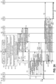
- FIGS 2A and 2B illustrate another example of a method 200 for cleaning up hanging LI resources when an SMF fails.
- the entities that are involved in performing the method 200 include an SMF set 202 that includes a first SMF 202-1, a second SMF 202-2, and a third SMF 202-3.
- Other entities that are involved in performing the method 200 include an access and mobility function (AMF) 204, a lawful interception provisioning function (LIPF) 206, a UDSF 208, an NRF 210, a UPF 212, and a mediation and delivery function (MDF) 214.
- AMF access and mobility function
- LIPF lawful interception provisioning function
- MDF mediation and delivery function
- the SMF set 202 is created.
- each of the SMFs in the SMF set 202 is configured with identifying information about the other SMFs in the SMF set 202.
- the identifying information for a particular SMF can include the NRF registered UUID and the NEID corresponding to that SMF.
- the first SMF 202-1 can be configured with the NRF registered UUID and the NEID for the second SMF 202-2 and the third SMF 202-3.
- the second SMF 202-2 can be configured with the NRF registered UUID and the NEID for the first SMF 202-1 and the third SMF 202-3.
- the third SMF 202-3 can be configured with the NRF registered UUID and the NEID for the first SMF 202-1 and the second SMF 202-2.
- each of the SMFs in the SMF set 202 creates a record in the UDSF 208.
- each of the SMFs in the SMF set 202 is configured with the same UPF list as its LI peers to send the LI messages.
- each of the SMFs in the SMF set 202 creates an auditing record in the UDSF 208. More specifically, act 209 of the method 200 includes act 209-1 performed by the first SMF 202-1, act 209-2 performed by the second SMF 202-2, and act 209-3 performed by the third SMF 202-3.
- act 209-1 the first SMF 202-1 creates a first auditing record in the UDSF 208.
- the claimant attribute of the first auditing record is set to an identifier corresponding to the first SMF 202-1 (e.g., NEID1).
- act 209-2 the second SMF 202-2 creates a second auditing record in the UDSF 208.
- the claimant attribute of the second auditing record is set to an identifier corresponding to the second SMF 202-2 (e.g., NEID2).
- the third SMF 202-3 creates a third auditing record in the UDSF 208.
- the claimant attribute of the third auditing record is set to an identifier corresponding to the third SMF 202-3 (e.g., NEID3).
- act 211 of the method 200 each of the SMFs in the SMF set 202 registers with the NRF 210. More specifically, act 211 of the method 200 includes acts 211-1a and 211-1b performed by the first SMF 202-1 and the NRF 210, acts 211-2a and 211-2b performed by the second SMF 202-2 and the NRF 210, and acts 211-3a and 211-3b performed by the third SMF 202-3 and the NRF 210.
- act 211-1a the first SMF 202-1 registers with the NRF 210.
- the first SMF 202-1 sends the NRF 210 an identifier (e.g., UUID1) corresponding to the first SMF 202-1.
- an identifier e.g., UUID1
- the NRF 210 acknowledges the registration of the first SMF 202-1.
- the second SMF 202-2 registers with the NRF 210.
- the second SMF 202-2 sends the NRF 210 an identifier (e.g., UUID2) corresponding to the second SMF 202-2.
- the NRF 210 acknowledges the registration of the second SMF 202-2.
- the third SMF 202-3 registers with the NRF 210.
- the third SMF 202-3 sends the NRF 210 an identifier (e.g., UUID3) corresponding to the third SMF 202-3.
- the NRF 210 acknowledges the registration of the third SMF 202-3.
- destinations are provisioned on all of the SMFs in the SMF set 202.
- act 215 of the method 200 the LIPF 206 activates a task request for each of the SMFs in the SMF set 202. More specifically, act 215 of the method 200 includes acts 215-1a and 215-1b performed by the LIPF 206 and the first SMF 202-1, acts 215-2a and 215-2b performed by the LIPF 206 and the second SMF 202-2, and acts 215-3a and 215-3b performed by the LIPF 206 and the third SMF 202-3.
- act 215-1a the LIPF 206 sends an activate task request message to the first SMF 202-1.
- act 215-1b the first SMF 202-1 sends an activate task response message to the LIPF 206.
- the AMF 204 receives a message that causes the AMF 204 to establish a PDU session with the first SMF 202-1.
- the AMF 204 establishes a PDU session with the first SMF 202-1.
- the first SMF 202-1 sends a message to the MDF 214 to establish an Intercept Related Information (IRI) event.
- IRI Intercept Related Information
- act 223 of the method 200 a destination is created with respect to the first SMF 202-1. More specifically, act 223 of the method 200 includes acts 223-1 and 223-2 performed by the first SMF 202-1 and the UPF 212.
- act 223-1 the first SMF 202-1 sends a CreateDestination request message to the UPF 212.
- the CreateDestination request message is sent only if the first task is getting provisioned.
- act 223-2 the UPF 212 sends a CreateDestination response message to the first SMF 202-1 (if the CreateDestination request message is sent).
- the CreateDestination response message acknowledges the receipt of the CreateDestination request message and indicates that the request to create the destination has been completed.
- act 225 of the method 200 a task is activated with respect to the first SMF 202-1. More specifically, act 225 of the method 200 includes acts 225-1 and 225-2 performed by the first SMF 202-1 and the UPF 212.
- act 225-1 the first SMF 202-1 sends an ActivateTask request message to the UPF 212.
- act 225-2 the UPF 212 sends an ActivateTask response message to the first SMF 202-1.
- the ActivateTask response message acknowledges the receipt of the ActivateTask request message and indicates that the request to activate the task has been completed.
- the UPF 212 provides intercept data to the MDF 214.
- act 229 of the method 200 the NRF 210 notifies the other SMFs in the SMF set 202 that the first SMF 202-1 has experienced a failure and is unavailable. More specifically, act 229 of the method 200 includes acts 229-1 and 229-2. In act 229-1, the NRF 210 notifies the second SMF 202-2 about the failure of the first SMF 202-1. In act 229-2, the NRF 210 notifies the third SMF 202-3 about the failure of the first SMF 202-1.
- the NRF 210 notifies the AMF 204 about the failure of the first SMF 202-1.
- an audit mechanism is performed.
- only one SMF in the SMF set 202 will be able to become the new owner of the auditing record corresponding to the first SMF 202-1.
- the new owner will then be responsible for the cleanup of hanging LI resources corresponding to the first SMF 202-1.
- the second SMF 202-2 becomes the new owner of the auditing record corresponding to the first SMF 202-1. This is shown in act 235 of the method 200.
- the second SMF 202-2 receives signaling in act 237 of the method 200.
- the signaling can come from entities such as the PCF and/or the AMF 204 and/or the LIPF 206.
- act 241 of the method 200 a task is activated with respect to the second SMF 202-2. More specifically, act 241 of the method 200 includes acts 241-1 and 241-2 performed by the second SMF 202-2 and the UPF 212. In act 241-1, the second SMF 202-2 sends an ActivateTask request message to the UPF 212. In act 241-2, the UPF 212 sends an ActivateTask response message to the second SMF 202-2. The ActivateTask response message acknowledges the receipt of the ActivateTask request message and indicates that the request to activate the task has been completed.
- the UPF 212 provides intercept data to the MDF 214.
- the second SMF 202-2 sends a message to the MDF 214 to establish an IRI event.
- act 247 of the method 200 the second SMF 202-2 deactivates all tasks associated with the first SMF 202-1. More specifically, act 247 of the method 200 includes acts 247-1 and 247-2 performed by the second SMF 202-2 and the UPF 212. In act 247-1, the second SMF 202-2 sends a DeactivateAllTasks request message to the UPF 212. The DeactivateAllTasks request message includes a request to delete all tasks associated with the first SMF 202-1. In act 247-2, the UPF 212 sends a DeactivateAllTasks response message to the second SMF 202-2.
- the DeactivateAllTasks response message acknowledges the receipt of the DeactivateAllTasks request message and indicates that the request to delete all tasks associated with the first SMF 202-1 has been completed.
- the DeactivateAllTasks request message is a node-level message that doesn't have to include specific target identifiers.
- the UPF 212 can identify all the targets to be deactivated based on an identifier (e.g., an ADMFID) that is included in the DeactivateAllTasks request message.
- act 249 of the method 200 the tasks associated with the first SMF 202-1 are removed and interception is stopped.
- act 251 of the method 200 the second SMF 202-2 removes all destinations associated with the first SMF 202-1. More specifically, act 251 of the method 200 includes acts 251-1 and 251-2 performed by the second SMF 202-2 and the UPF 212. In act 251-1, the second SMF 202-2 sends a RemoveAllDestinations request message to the UPF 212. The RemoveAllDestinations request message includes a request to remove all destinations associated with the first SMF 202-1. In act 251-2, the UPF 212 sends a RemoveAllDestinations response message to the second SMF 202-2. The RemoveAllDestinations response message acknowledges the receipt of the RemoveAllDestinations request message and indicates that the request to remove all destinations associated with the first SMF 202-1 has been completed.
- the RemoveAllDestinations request message is a node-level message that doesn't have to include specific destination identifiers.
- the UPF 212 can identify all the destinations to be removed based on an identifier (e.g., an ADMFID) that is included in the RemoveAllDestinations request message.
- an identifier e.g., an ADMFID
- the 5G system architecture includes many different network functions (NFs).
- a network function (NF) can refer to a functional building block within a network infrastructure.
- An NF can have well-defined external interfaces and well-defined functional behavior.
- NFs that are included in the 5G system architecture and that may be used to implement one or more aspects of the techniques disclosed herein include a user plane function (UPF), a session management function (SMF), an NF repository function (NRF), an unstructured data storage network function (UDSF), an access and mobility management function (AMF), and a lawful interception provisioning function (LIPF).
- UPF user plane function
- SMF session management function
- NRF NF repository function
- UDF unstructured data storage network function
- AMF access and mobility management function
- LIPF lawful interception provisioning function
- the UPF is defined in 3GPP TS 23.501.
- the UPF provides the interconnect point between the mobile infrastructure and the Data Network (DN), i.e. encapsulation and decapsulation of GPRS Tunnelling Protocol for the user plane (GTP-U).
- the UPF also provides the Protocol Data Unit (PDU) session anchor point for providing mobility within and between Radio Access Technologies (RATs), including sending one or more end marker packets to the gNB.
- RATs Radio Access Technologies
- the UPF also provides packet routing and forwarding, including performing the role of an Uplink Classifier / UL-CL (directing flows to specific data networks based on traffic matching filters) and a branching point, when acting as an Intermediate UPF (I-UPF) multi-homed to more than one PDU session anchor (PSA).
- I-UPF Intermediate UPF
- the UPF also provides application detection using Service Data Flow (SDF) traffic filter templates or 3-tuple (protocol, server-side IP address and port number) Packet Flow Description (PFD) received from the SMF.
- SDF Service Data Flow
- PFD Packet Flow Description
- the UPF also provides per-flow QoS handling, including transport level packet marking for uplink (UL) and downlink (DL), rate limiting and reflective QoS (DSCP) marking on the DL.
- DL uplink
- DSCP rate limiting and reflective QoS
- the UPF also provides traffic usage reporting for billing and the Lawful Intercept (LI) collector interface.
- LI Lawful Intercept
- a session management function can be responsible for creating, updating, and removing PDU sessions, and managing session context with the UPF.
- a network function repository function can maintain a list of available NF instances and their profiles.
- the NRF can also perform service registration and discovery so that different NFs can find each other (e.g., via application programming interfaces (APIs)).
- APIs application programming interfaces
- An unstructured data storage network function can be configured to support storage and retrieval of unstructured data by any NF.
- An access and mobility management function can be configured to receive all connection and session related information from UEs but is responsible only for handling connection and mobility management tasks. All messages related to session management can be forwarded to the SMF.
- Intercept Related Information is defined as the intercept related information as forwarded from the Mediation and Delivery Function 2 (over the LI_HI2 interface) to the Law Enforcement Monitoring Facility.
- An IRI event is defined as a network procedure or event that created an xIRI in the Point of Interception.
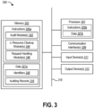
- Figure 3 illustrates certain components that can be included within a computing system 300.
- the computing system 300 can be used to implement the actions and operations that have been described herein in connection with various network elements (e.g., an SMF set, a UDSF, an NRF, a UPF).
- network elements e.g., an SMF set, a UDSF, an NRF, a UPF.
- a plurality of computing systems 300 can collectively implement the actions and operations that have been described herein in connection with various network elements.
- the computing system 300 includes a processor 301 and memory 303 in electronic communication with the processor 301. Instructions 305a and data 307a can be stored in the memory 303.
- the instructions 305a can be executable by the processor 301 to implement some or all of the methods, steps, operations, actions, or other functionality disclosed herein related to various network elements. Executing the instructions 305a can involve the use of the data 307a that is stored in the memory 303.
- various instructions 305b can be loaded onto the processor 301, and various pieces of data 307b can be loaded onto the processor 301.
- any of the various examples of modules and components described herein in connection with a network element can be implemented, partially or wholly, as instructions 305a stored in memory 303 and executed by the processor 301.
- Any of the various examples of data described herein in connection with a network element can be among the data 307a that is stored in memory 303 and used during execution of the instructions 305a by the processor 301.
- processor 301 Although just a single processor 301 and a single memory 303 are shown in the computing system 300 of Figure 9, in an alternative configuration, a combination of processors and/or a combination of memory devices could be used.
- the instructions 305a in the memory 303 can include one or more modules that can be executable by the processor 301 to perform some or all aspects of the methods that have been described herein in connection with various network elements (e.g., the method 100 shown in Figures 1A-1E , the method 200 shown in Figures 2A-2B ).
- the instructions 305a can include one or more audit module(s) 342 that are configured to perform an audit mechanism as disclosed herein (e.g., an audit mechanism corresponding to acts 115 through 121 of the method 100 shown in Figures 1A-1E ).
- the instructions 305a can also include one or more LI resource cleanup module(s) 344 that are configured to clean up hanging LI resources as disclosed herein (e.g., as in acts 123 through 127 of the method 100 shown in Figures 1A-1E ).
- the instructions 305a stored in the memory 303 can include one or more request handling module(s) 346 that are configured to respond to update requests (e.g., as in acts 117 and 121 in the method 100 shown in Figures 1A-1E ).
- the data 307a stored in the memory 303 can include any of the various examples of data described herein in connection with various network elements.
- the data 307a stored in the memory 303 can represent data that is stored, accessed, or otherwise used in connection with the methods that have been described herein in connection with various network elements (e.g., the method 100 shown in Figures 1A-1E , the method 200 shown in Figures 2A-2B ).
- the data 307a stored in the memory 303 can include a plurality of identifiers 348.
- each SMF can be configured with the NEID as well as the NF instance ID of all other SMFs in the set.
- the data 307a stored in the memory 303 can also include a plurality of auditing records 316.
- the auditing records 316 shown in Figure 3 can represent any of the auditing records described herein in connection with a UDSF (e.g., the auditing records 116-1, 116-2, 116-3 shown in Figure 1C ).
- FIG. 3 The specific instructions 305a and data 307a shown in Figure 3 are provided for purposes of example only and should not be interpreted as limiting the scope of the present disclosure.
- a computing system 300 that implements any of the techniques disclosed herein can include other instructions 305a and/or other data 307a in addition to or instead of what is specifically shown in Figure 3 .
- the computing system 300 can also include various other components, including one or more communication interfaces 309, one or more input devices 311, and one or more output devices 313.
- the communication interface(s) 309 can be configured to communicate with other computing systems and/or networking devices. This includes receiving data transmissions from other computing systems and/or networking devices, and also sending data transmissions to other computing systems and/or networking devices.
- the various components of the computing system 300 can be coupled together by one or more buses, which can include a power bus, a control signal bus, a status signal bus, a data bus, etc.
- buses can include a power bus, a control signal bus, a status signal bus, a data bus, etc.
- the various buses are illustrated in Figure 9 as a bus system 319.
- the techniques disclosed herein can be implemented in hardware, software, firmware, or any combination thereof, unless specifically described as being implemented in a specific manner. Any features described as modules, components, or the like can also be implemented together in an integrated logic device or separately as discrete but interoperable logic devices. If implemented in software, the techniques can be realized at least in part by a non-transitory computer-readable medium having computer-executable instructions stored thereon that, when executed by at least one processor, perform some or all of the steps, operations, actions, or other functionality disclosed herein.
- the instructions can be organized into routines, programs, objects, components, data structures, etc., which can perform particular tasks and/or implement particular data types, and which can be combined or distributed as desired in various embodiments.
- processor should be interpreted broadly to encompass a general-purpose processor, a central processing unit (CPU), a microprocessor, a digital signal processor (DSP), a controller, a microcontroller, a state machine, and so forth. Under some circumstances, a “processor” may refer to an application specific integrated circuit (ASIC), a programmable logic device (PLD), a field programmable gate array (FPGA), etc.
- ASIC application specific integrated circuit
- PLD programmable logic device
- FPGA field programmable gate array
- processor may refer to a combination of processing devices, e.g., a combination of a digital signal processor (DSP) and a microprocessor, a plurality of microprocessors, one or more microprocessors in conjunction with a digital signal processor (DSP) core, or any other such configuration.
- memory should be interpreted broadly to encompass any electronic component capable of storing electronic information.
- the term “memory” may refer to various types of processor-readable media such as random access memory (RAM), read-only memory (ROM), non-volatile random access memory (NVRAM), programmable read-only memory (PROM), erasable programmable read-only memory (EPROM), electrically erasable PROM (EEPROM), flash memory, magnetic or optical data storage, registers, etc.
- RAM random access memory
- ROM read-only memory
- NVRAM non-volatile random access memory
- PROM programmable read-only memory
- EPROM erasable programmable read-only memory
- EEPROM electrically erasable PROM
- flash memory magnetic or optical data storage, registers, etc.
- instructions and “code” should be interpreted broadly to include any type of computer-readable statement(s).
- the terms “instructions” and “code” may refer to one or more programs, routines, sub-routines, functions, procedures, etc.
- “Instructions” and “code” may comprise a single computer-readable statement or many computer-readable statements.
- determining can encompass a wide variety of actions. For example, “determining” can include calculating, computing, processing, deriving, investigating, looking up (e.g., looking up in a table, a database or another data structure), ascertaining and the like. Also, “determining” can include receiving (e.g., receiving information), accessing (e.g., accessing data in a memory) and the like. Also, “determining” can include resolving, selecting, choosing, establishing and the like.
Landscapes
- Engineering & Computer Science (AREA)
- Technology Law (AREA)
- Computer Security & Cryptography (AREA)
- Computer Networks & Wireless Communication (AREA)
- Signal Processing (AREA)
- Computer Hardware Design (AREA)
- Computing Systems (AREA)
- General Engineering & Computer Science (AREA)
- Mobile Radio Communication Systems (AREA)
Claims (15)
- System (300), das es ermöglicht, hängende legale Abhörressourcen, LI, zu reinigen, wobei das System Folgendes umfasst:einen oder mehrere Prozessoren (301);einen Auslösefunktionssatz, umfassend eine Vielzahl von Auslösefunktionen;einen Datenspeicher, umfassend eine Vielzahl von Prüfdatensätzen (316), die der Vielzahl von Auslösefunktionen in dem Auslösefunktionssatz entsprechen, wobei jeder Prüfdatensatz ein Anspruchstellerattribut umfasst; undAnweisungen, die von einem oder mehreren Prozessoren ausgeführt werden können zum:Veranlassen, dass jede Auslösefunktion aus der Vielzahl von Auslösefunktionen eine Aktualisierungsanforderung (120) an den Datenspeicher sendet, als Reaktion auf die Benachrichtigung über eine fehlgeschlagene Auslösefunktion innerhalb des Auslösefunktionssatzes, wobei jede Aktualisierungsanforderung (120) eine Anforderung umfasst, die Eigentümerschaft des Prüfdatensatzes (116), der der fehlgeschlagenen Auslösefunktion entspricht, zu ändern;Auswählen einer Auslösefunktion als neuen Eigentümer des Prüfdatensatzes (116) entsprechend der fehlgeschlagenen Auslösefunktion, basierend zumindest teilweise auf einer Übereinstimmung zwischen dem Anspruchstellerattribut (118) in dem Prüfdatensatz (116) und einem Anspruchstellerfeld (122) in der Aktualisierungsanforderung (120), die von der Auslösefunktion gesendet wird; undVeranlassen, dass der neue Eigentümer des Prüfdatensatzes (116), der der fehlgeschlagenen Auslösefunktion entspricht, mindestens eine Anforderung an einen ausgelösten Abhörpunkt, POI, sendet, um eine LI-Ressource zu entfernen, die der fehlgeschlagenen Auslösefunktion entspricht.
- System nach Anspruch 1, wobei jede Aktualisierungsanforderung Folgendes umfasst:das Anspruchstellerfeld, das die fehlgeschlagene Auslösefunktion identifiziert; undeine Anforderung zur Änderung des Anspruchstellerattributs des Prüfdatensatzes in eine Kennung, die mit einem Absender der Aktualisierungsanfrage verknüpft ist.
- System nach Anspruch 2, wobei die Anforderung zur Änderung des Anspruchstellerattributs nur dann genehmigt wird, wenn das Anspruchstellerfeld mit dem Anspruchstellerattribut des Prüfdatensatzes übereinstimmt.
- System nach einem der vorangehenden Ansprüche, wobei:die fehlgeschlagene Auslösefunktion eine fehlgeschlagene Sitzungsverwaltungsfunktion, SMF, umfasst; unddie Vielzahl von Auslösefunktionen eine Vielzahl von SMFs umfasst.
- System nach einem der vorhergehenden Ansprüche, wobei der Datenspeicher eine unstrukturierte Datenspeicher-Netzwerkfunktion, UDSF, umfasst.
- System nach einem der vorhergehenden Ansprüche, wobei der ausgelöste POI in einer Benutzerebenenfunktion, UPF, liegt.
- System nach einem der vorhergehenden Ansprüche, ferner umfassend das Benachrichtigen der Vielzahl von Auslösefunktionen in dem Auslösefunktionssatz über die fehlgeschlagene Auslösefunktion.
- System nach Anspruch 7, ferner umfassend das Veranlassen, dass jede Auslösefunktion aus der Vielzahl von Auslösefunktionen sich bei einer Netzwerkfunktions-Repository-Funktion registriert.
- System nach einem der vorhergehenden Ansprüche, wobei die mindestens eine Anforderung, die an den ausgelösten POI gesendet wird, umfasst:eine erste Anforderung zum Deaktivieren aller Aufgaben, die mit der fehlgeschlagenen Auslösefunktion verknüpft sind; undeine zweite Anforderung zum Entfernen aller Ziele, die mit der fehlgeschlagenen Auslösefunktion verknüpft sind.
- System nach einem der vorhergehenden Ansprüche, ferner umfassend das Veranlassen, dass der neue Eigentümers des Prüfprotokolls, das der fehlgeschlagenen Auslösefunktion entspricht, eine Anforderung an den Datenspeicher sendet, um das Prüfprotokoll aus dem Datenspeicher zu entfernen.
- Verfahren zum Ermöglichen des Reinigens von hängenden legalen Abhörressourcen, LI, wobei das Verfahren durch eine Auslösefunktion implementiert wird, die zu einem Auslösefunktionssatz gehört, der eine Vielzahl von Auslösefunktionen umfasst, wobei das Verfahren Folgendes umfasst:Empfangen einer Benachrichtigung über eine fehlgeschlagene Auslösefunktion in dem Auslösefunktionssatz;Senden einer Aktualisierungsanforderung (120) an einen Datenspeicher, der eine Vielzahl von Prüfdatensätzen (316) umfasst, die der Vielzahl von Auslösefunktionen entsprechen, als Reaktion auf die Benachrichtigung, wobei die Aktualisierungsanforderung (120) eine Anforderung umfasst, die Eigentümerschaft eines Prüfdatensatzes (116), der der fehlgeschlagenen Auslösefunktion entspricht, zu ändern;als Antwort auf das Senden der Aktualisierungsanforderung (120) Empfangen einer Angabe, dass die Auslösefunktion als neuer Eigentümer des Prüfdatensatzes (116) ausgewählt wurde, basierend zumindest teilweise auf einer Übereinstimmung zwischen einem Anspruchstellerattribut (118) in dem Prüfdatensatz (116) und einem Anspruchstellerfeld (122) in der von der Auslösefunktion gesendeten Aktualisierungsanforderung (120); undals Reaktion auf das Empfangen der Angabe Senden mindestens einer Anforderung an einen ausgelösten Abhörpunkt, POI, um eine LI-Ressource zu entfernen, die der fehlgeschlagenen Auslösefunktion entspricht.
- Verfahren nach Anspruch 11, wobei:das Anspruchstellerfeld die fehlgeschlagene Auslösefunktion identifiziert; unddie Aktualisierungsanforderung eine Anforderung zur Änderung des Anspruchstellerattributs des Prüfdatensatzes in einen mit der Auslösefunktion verknüpften Identifikator umfasst.
- Verfahren nach Anspruch 11 oder Anspruch 12, wobei:die Auslösefunktion eine Sitzungsverwaltungsfunktion, SMF, umfasst;die fehlgeschlagene Auslösefunktion eine fehlgeschlagene SMF umfasst; unddie Vielzahl von Auslösefunktionen eine Vielzahl von SMFs umfasst.
- Verfahren nach einem der Ansprüche 11 bis 13, wobei der Datenspeicher eine unstrukturierte Datenspeicher-Netzwerkfunktion, UDSF, umfasst.
- Verfahren nach einem der Ansprüche 11 bis 14, wobei der ausgelöste POI in einer Benutzerebenenfunktion UPF liegt.
Applications Claiming Priority (3)
| Application Number | Priority Date | Filing Date | Title |
|---|---|---|---|
| IN202141010829 | 2021-03-15 | ||
| US17/341,313 US11601818B2 (en) | 2021-03-15 | 2021-06-07 | Cleaning up hanging lawful interception resources from a triggered point of interception when a triggering function fails |
| PCT/US2022/018259 WO2022197432A1 (en) | 2021-03-15 | 2022-03-01 | Cleaning up hanging lawful interception resources from a triggered point of interception when a triggering function fails |
Publications (2)
| Publication Number | Publication Date |
|---|---|
| EP4309396A1 EP4309396A1 (de) | 2024-01-24 |
| EP4309396B1 true EP4309396B1 (de) | 2025-04-23 |
Family
ID=80780996
Family Applications (1)
| Application Number | Title | Priority Date | Filing Date |
|---|---|---|---|
| EP22710897.4A Active EP4309396B1 (de) | 2021-03-15 | 2022-03-01 | Reinigung hängender legaler abhörressourcen von einem ausgelösten abhörpunkt bei ausfall einer auslösefunktion |
Country Status (3)
| Country | Link |
|---|---|
| US (1) | US11877158B2 (de) |
| EP (1) | EP4309396B1 (de) |
| WO (1) | WO2022197432A1 (de) |
Families Citing this family (1)
| Publication number | Priority date | Publication date | Assignee | Title |
|---|---|---|---|---|
| TWI826194B (zh) * | 2022-12-20 | 2023-12-11 | 明泰科技股份有限公司 | 相容於雲原生虛擬網路層的使用者層功能(upf)封包處理方法及計算裝置 |
Family Cites Families (7)
| Publication number | Priority date | Publication date | Assignee | Title |
|---|---|---|---|---|
| EP1859606A1 (de) * | 2005-03-18 | 2007-11-28 | TELEFONAKTIEBOLAGET LM ERICSSON (publ) | Legales abfangen von unautorisierten teilnehmern und geräten |
| WO2007073252A1 (en) * | 2005-12-22 | 2007-06-28 | Telefonaktiebolaget Lm Ericsson (Publ) | Provisioning of user information |
| CN101076196B (zh) * | 2007-07-04 | 2012-01-11 | 中兴通讯股份有限公司 | 合法监听系统和方法 |
| WO2015005651A1 (en) * | 2013-07-08 | 2015-01-15 | Samsung Electronics Co., Ltd. | Lawful interception method and apparatus of d2d communication-capable terminal |
| EP3763142B1 (de) * | 2018-03-07 | 2022-05-04 | Telefonaktiebolaget LM Ericsson (PUBL) | Verfahren und vorrichtung zur korrelation in einem mediationssystem für legales abhören |
| WO2020263141A1 (en) * | 2019-06-27 | 2020-12-30 | Telefonaktiebolaget Lm Ericsson (Publ) | Method, node and computer program of lawful interception systems and networks |
| WO2021126020A1 (en) * | 2019-12-16 | 2021-06-24 | Telefonaktiebolaget Lm Ericsson (Publ) | Managing lawful interception information |
-
2022
- 2022-03-01 EP EP22710897.4A patent/EP4309396B1/de active Active
- 2022-03-01 WO PCT/US2022/018259 patent/WO2022197432A1/en not_active Ceased
-
2023
- 2023-03-03 US US18/178,352 patent/US11877158B2/en active Active
Also Published As
| Publication number | Publication date |
|---|---|
| US11877158B2 (en) | 2024-01-16 |
| US20230209358A1 (en) | 2023-06-29 |
| EP4309396A1 (de) | 2024-01-24 |
| WO2022197432A1 (en) | 2022-09-22 |
Similar Documents
| Publication | Publication Date | Title |
|---|---|---|
| US20250150939A1 (en) | Accepting a network slice based on location based network slice coexistence rules | |
| US12082275B2 (en) | Establishing a session or cellular internet of things packet transmission | |
| US11818608B2 (en) | Third party charging in a wireless network | |
| US11690005B2 (en) | Network slice for visited network | |
| US12160924B2 (en) | Network exposure function and wireless device with releasable connection | |
| US11070627B2 (en) | Discovery of a user plane function that supports cellular IoT optimization | |
| US11405851B2 (en) | Closed access group overload and congestion control | |
| US11895717B2 (en) | Charging aggregation control for network slices | |
| US11245539B2 (en) | Charging control for non-public network | |
| EP3881635B1 (de) | Anwendungsauslösung für eine drahtlose vorrichtung | |
| ES2964564T3 (es) | Métodos, aparatos y sistema para desactivación de sesiones de PDU | |
| CN110583034B (zh) | 在移动通信网络中接入与提供网络切片的方法、系统和装置 | |
| JP2023525925A (ja) | ネットワークアクセス方法、装置、およびシステム | |
| EP4309396B1 (de) | Reinigung hängender legaler abhörressourcen von einem ausgelösten abhörpunkt bei ausfall einer auslösefunktion | |
| US11601818B2 (en) | Cleaning up hanging lawful interception resources from a triggered point of interception when a triggering function fails | |
| US20240381098A1 (en) | Methods, devices and system for lawful interception by subscribing to a notification | |
| KR100625235B1 (ko) | 휴대 인터넷 시스템에서의 연결 관리 제어 방법 |
Legal Events
| Date | Code | Title | Description |
|---|---|---|---|
| STAA | Information on the status of an ep patent application or granted ep patent |
Free format text: STATUS: UNKNOWN |
|
| STAA | Information on the status of an ep patent application or granted ep patent |
Free format text: STATUS: THE INTERNATIONAL PUBLICATION HAS BEEN MADE |
|
| PUAI | Public reference made under article 153(3) epc to a published international application that has entered the european phase |
Free format text: ORIGINAL CODE: 0009012 |
|
| STAA | Information on the status of an ep patent application or granted ep patent |
Free format text: STATUS: REQUEST FOR EXAMINATION WAS MADE |
|
| 17P | Request for examination filed |
Effective date: 20230814 |
|
| AK | Designated contracting states |
Kind code of ref document: A1 Designated state(s): AL AT BE BG CH CY CZ DE DK EE ES FI FR GB GR HR HU IE IS IT LI LT LU LV MC MK MT NL NO PL PT RO RS SE SI SK SM TR |
|
| DAV | Request for validation of the european patent (deleted) | ||
| DAX | Request for extension of the european patent (deleted) | ||
| GRAP | Despatch of communication of intention to grant a patent |
Free format text: ORIGINAL CODE: EPIDOSNIGR1 |
|
| STAA | Information on the status of an ep patent application or granted ep patent |
Free format text: STATUS: GRANT OF PATENT IS INTENDED |
|
| INTG | Intention to grant announced |
Effective date: 20241113 |
|
| GRAS | Grant fee paid |
Free format text: ORIGINAL CODE: EPIDOSNIGR3 |
|
| P01 | Opt-out of the competence of the unified patent court (upc) registered |
Free format text: CASE NUMBER: APP_4670/2025 Effective date: 20250128 |
|
| GRAA | (expected) grant |
Free format text: ORIGINAL CODE: 0009210 |
|
| STAA | Information on the status of an ep patent application or granted ep patent |
Free format text: STATUS: THE PATENT HAS BEEN GRANTED |
|
| AK | Designated contracting states |
Kind code of ref document: B1 Designated state(s): AL AT BE BG CH CY CZ DE DK EE ES FI FR GB GR HR HU IE IS IT LI LT LU LV MC MK MT NL NO PL PT RO RS SE SI SK SM TR |
|
| REG | Reference to a national code |
Ref country code: GB Ref legal event code: FG4D |
|
| REG | Reference to a national code |
Ref country code: CH Ref legal event code: EP |
|
| REG | Reference to a national code |
Ref country code: DE Ref legal event code: R096 Ref document number: 602022013544 Country of ref document: DE |
|
| REG | Reference to a national code |
Ref country code: IE Ref legal event code: FG4D |
|
| REG | Reference to a national code |
Ref country code: NL Ref legal event code: MP Effective date: 20250423 |
|
| PG25 | Lapsed in a contracting state [announced via postgrant information from national office to epo] |
Ref country code: NL Free format text: LAPSE BECAUSE OF FAILURE TO SUBMIT A TRANSLATION OF THE DESCRIPTION OR TO PAY THE FEE WITHIN THE PRESCRIBED TIME-LIMIT Effective date: 20250423 |
|
| REG | Reference to a national code |
Ref country code: AT Ref legal event code: MK05 Ref document number: 1789011 Country of ref document: AT Kind code of ref document: T Effective date: 20250423 |
|
| PG25 | Lapsed in a contracting state [announced via postgrant information from national office to epo] |
Ref country code: FI Free format text: LAPSE BECAUSE OF FAILURE TO SUBMIT A TRANSLATION OF THE DESCRIPTION OR TO PAY THE FEE WITHIN THE PRESCRIBED TIME-LIMIT Effective date: 20250423 Ref country code: PT Free format text: LAPSE BECAUSE OF FAILURE TO SUBMIT A TRANSLATION OF THE DESCRIPTION OR TO PAY THE FEE WITHIN THE PRESCRIBED TIME-LIMIT Effective date: 20250825 Ref country code: ES Free format text: LAPSE BECAUSE OF FAILURE TO SUBMIT A TRANSLATION OF THE DESCRIPTION OR TO PAY THE FEE WITHIN THE PRESCRIBED TIME-LIMIT Effective date: 20250423 |
|
| REG | Reference to a national code |
Ref country code: LT Ref legal event code: MG9D |
|
| PG25 | Lapsed in a contracting state [announced via postgrant information from national office to epo] |
Ref country code: NO Free format text: LAPSE BECAUSE OF FAILURE TO SUBMIT A TRANSLATION OF THE DESCRIPTION OR TO PAY THE FEE WITHIN THE PRESCRIBED TIME-LIMIT Effective date: 20250723 Ref country code: GR Free format text: LAPSE BECAUSE OF FAILURE TO SUBMIT A TRANSLATION OF THE DESCRIPTION OR TO PAY THE FEE WITHIN THE PRESCRIBED TIME-LIMIT Effective date: 20250724 |
|
| PG25 | Lapsed in a contracting state [announced via postgrant information from national office to epo] |
Ref country code: PL Free format text: LAPSE BECAUSE OF FAILURE TO SUBMIT A TRANSLATION OF THE DESCRIPTION OR TO PAY THE FEE WITHIN THE PRESCRIBED TIME-LIMIT Effective date: 20250423 |
|
| PG25 | Lapsed in a contracting state [announced via postgrant information from national office to epo] |
Ref country code: BG Free format text: LAPSE BECAUSE OF FAILURE TO SUBMIT A TRANSLATION OF THE DESCRIPTION OR TO PAY THE FEE WITHIN THE PRESCRIBED TIME-LIMIT Effective date: 20250423 |
|
| PG25 | Lapsed in a contracting state [announced via postgrant information from national office to epo] |
Ref country code: HR Free format text: LAPSE BECAUSE OF FAILURE TO SUBMIT A TRANSLATION OF THE DESCRIPTION OR TO PAY THE FEE WITHIN THE PRESCRIBED TIME-LIMIT Effective date: 20250423 |
|
| PG25 | Lapsed in a contracting state [announced via postgrant information from national office to epo] |
Ref country code: AT Free format text: LAPSE BECAUSE OF FAILURE TO SUBMIT A TRANSLATION OF THE DESCRIPTION OR TO PAY THE FEE WITHIN THE PRESCRIBED TIME-LIMIT Effective date: 20250423 |
|
| PG25 | Lapsed in a contracting state [announced via postgrant information from national office to epo] |
Ref country code: RS Free format text: LAPSE BECAUSE OF FAILURE TO SUBMIT A TRANSLATION OF THE DESCRIPTION OR TO PAY THE FEE WITHIN THE PRESCRIBED TIME-LIMIT Effective date: 20250723 |
|
| PG25 | Lapsed in a contracting state [announced via postgrant information from national office to epo] |
Ref country code: IS Free format text: LAPSE BECAUSE OF FAILURE TO SUBMIT A TRANSLATION OF THE DESCRIPTION OR TO PAY THE FEE WITHIN THE PRESCRIBED TIME-LIMIT Effective date: 20250823 |
|
| PG25 | Lapsed in a contracting state [announced via postgrant information from national office to epo] |
Ref country code: LV Free format text: LAPSE BECAUSE OF FAILURE TO SUBMIT A TRANSLATION OF THE DESCRIPTION OR TO PAY THE FEE WITHIN THE PRESCRIBED TIME-LIMIT Effective date: 20250423 |
|
| PG25 | Lapsed in a contracting state [announced via postgrant information from national office to epo] |
Ref country code: DK Free format text: LAPSE BECAUSE OF FAILURE TO SUBMIT A TRANSLATION OF THE DESCRIPTION OR TO PAY THE FEE WITHIN THE PRESCRIBED TIME-LIMIT Effective date: 20250423 Ref country code: SM Free format text: LAPSE BECAUSE OF FAILURE TO SUBMIT A TRANSLATION OF THE DESCRIPTION OR TO PAY THE FEE WITHIN THE PRESCRIBED TIME-LIMIT Effective date: 20250423 |