EP4308322B1 - Verlorenes wachsformherstellungsverfahren - Google Patents
Verlorenes wachsformherstellungsverfahren Download PDFInfo
- Publication number
- EP4308322B1 EP4308322B1 EP22713704.9A EP22713704A EP4308322B1 EP 4308322 B1 EP4308322 B1 EP 4308322B1 EP 22713704 A EP22713704 A EP 22713704A EP 4308322 B1 EP4308322 B1 EP 4308322B1
- Authority
- EP
- European Patent Office
- Prior art keywords
- wax
- staple
- core elements
- branches
- core
- Prior art date
- Legal status (The legal status is an assumption and is not a legal conclusion. Google has not performed a legal analysis and makes no representation as to the accuracy of the status listed.)
- Active
Links
Images


Classifications
-
- B—PERFORMING OPERATIONS; TRANSPORTING
- B22—CASTING; POWDER METALLURGY
- B22C—FOUNDRY MOULDING
- B22C7/00—Patterns; Manufacture thereof so far as not provided for in other classes
- B22C7/02—Lost patterns
-
- B—PERFORMING OPERATIONS; TRANSPORTING
- B22—CASTING; POWDER METALLURGY
- B22C—FOUNDRY MOULDING
- B22C21/00—Flasks; Accessories therefor
- B22C21/12—Accessories
- B22C21/14—Accessories for reinforcing or securing moulding materials or cores, e.g. gaggers, chaplets, pins, bars
-
- B—PERFORMING OPERATIONS; TRANSPORTING
- B22—CASTING; POWDER METALLURGY
- B22C—FOUNDRY MOULDING
- B22C9/00—Moulds or cores; Moulding processes
- B22C9/02—Sand moulds or like moulds for shaped castings
- B22C9/04—Use of lost patterns
-
- B—PERFORMING OPERATIONS; TRANSPORTING
- B22—CASTING; POWDER METALLURGY
- B22C—FOUNDRY MOULDING
- B22C9/00—Moulds or cores; Moulding processes
- B22C9/10—Cores; Manufacture or installation of cores
- B22C9/103—Multipart cores
-
- B—PERFORMING OPERATIONS; TRANSPORTING
- B22—CASTING; POWDER METALLURGY
- B22C—FOUNDRY MOULDING
- B22C9/00—Moulds or cores; Moulding processes
- B22C9/22—Moulds for peculiarly-shaped castings
-
- B—PERFORMING OPERATIONS; TRANSPORTING
- B22—CASTING; POWDER METALLURGY
- B22D—CASTING OF METALS; CASTING OF OTHER SUBSTANCES BY THE SAME PROCESSES OR DEVICES
- B22D25/00—Special casting characterised by the nature of the product
- B22D25/02—Special casting characterised by the nature of the product by its peculiarity of shape; of works of art
Definitions
- This presentation concerns the field of turbines, in particular that of turbomachine turbines, and aims at a manufacturing process by lost wax casting of parts, in particular blades, said parts comprising cavities intended for the circulation of cooling fluids.
- Turbine blades are subjected to high thermal stresses and include means of cooling by circulation of a heat transfer fluid, generally air in the case of a gas turbine engine, inside cavities formed in the blade.
- a heat transfer fluid generally air in the case of a gas turbine engine
- Turbine blades are generally manufactured by casting, particularly by lost-wax casting. This technique consists of making a wax model of the part to be manufactured. The wax model is enclosed in a ceramic shell mold. This is manufactured by successively dipping the wax model in slips containing a ceramic material and by stuccoing the layer formed between each dipping. The wax model is removed during an initial firing at a suitable temperature. The shell mold is then fired at a high temperature to give it the strength required for casting the metal.
- the shell mold then has a cavity forming the image of the hollow model, molten metal being poured into said cavity. After cooling, the shell mold is broken to release the part. The latter then undergoes a finishing treatment.
- This phase of the process first includes the separate manufacture of the core element(s) by molding a ceramic material consolidated by a binder, their assembly if necessary, and the placement of the core element(s) in a wax mold. A wax model is thus produced by injecting wax into the wax mold. This model is a replica of the part to be obtained.
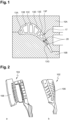
- FIG. 1 represents, in section perpendicular to the axis of the part, a wax mold 10 whose internal wall is the image of the part to be obtained.
- This wax mold is here in two parts 10A and 10B.
- a core 13 composed of a plurality of branches 13A to 13G parallel to each other is arranged in the mold 10. The branches define between them spaces which will form partitions after the casting of the metal.
- platinum pins 20 are arranged between the core 13G and the wall 17 of the mold, the pins 20 acting as a spacer.
- a ceramic shell mold is then obtained after extraction of the wax model. Molten metal is then poured into the space between the walls of the ceramic mold and those of the core. The pins are then melted and dissolved in the metal. The ceramic core is then removed by appropriate treatment.
- the function of the pins is to maintain a space between the walls of the core and the inner wall of the mold, especially when injecting wax into the wax mold. This ensures that the dimensions of the wax model, and therefore of the ceramic shell mold and the metal part to be manufactured, are respected.
- the aim of this presentation is to propose a method for manufacturing a cavity part by wax casting while ensuring precise thicknesses of the walls of the part, in a reliable and inexpensive manner.
- the clip makes it possible to maintain the core elements in position relative to each other and/or relative to the internal surface of the wax mold, in particular during the injection of wax into the wax mold.
- the wax model obtained thus forms a replica whose dimensions are controlled, so that the part manufactured on the basis of this model matches the dimensional specifications.
- One or two clips can be used to hold two core elements in place relative to each other, which helps reduce the cost of the manufacturing process.
- the clip once the clip is in position, for example after gluing, it will remain in place throughout the process without the risk of losing it or moving it slightly, which would cause poor positioning.
- the clip helps to guarantee the wall thickness around the core.
- the core elements may partly have a shape complementary to the cavity and their assembly may entirely have the shape complementary to the cavity.
- the staple can have a general shape of U, C, V or M.
- the part to be manufactured may comprise at least two cavities each formed by a core whose shape may depend on the shape of the cavity to be produced.
- the method may comprise, prior to assembling the two core elements by the clip, a step of positioning at least one spacer between the two core elements to maintain said core elements at a predetermined distance from each other. Said spacer may be removed after fixing the clip. The two core elements may be assembled directly by the clip without using the spacer.
- At least one, in particular each, of the branches of the staple can be held in the orifice by gluing.
- the bonding of one of the branches of the staple can be carried out by a glue, for example of the Loctite ® type, wax or any other suitable means to hold said branch in the corresponding hole.
- At least one, in particular each, orifice of one of the core elements may be a blind orifice. This makes it possible to limit the length of the branches of the staple.
- At least one, in particular each, orifice of one of the core elements may be a through orifice, the corresponding branch of the clip passing through said orifice and the free end of said branch being folded over the corresponding core so as to lock the clip in position. This makes it possible to ensure that the core elements are held in relative position more reliably.
- the central part and the two branches of the clip may have a circular section.
- At least one, in particular each, orifice of one of the core elements may have a diameter of between 0.5 mm and 1 mm, in particular equal to 0.8 mm.
- the clip may have a diameter substantially identical to the diameter of the corresponding orifice(s), with a mounting clearance which is for example of the order of 0.1 mm.
- the clip can be made of platinum or another material, depending on the metal material intended for casting.
- the cores may have first side surfaces facing the same side. Said clip may be placed so that the central branch is against said first side faces of the cores.
- the branches of the staple can extend in the same direction across the cores.
- the distal portions of the staple branches may be folded over second lateral surfaces of the cores opposite the first lateral surfaces.
- the staple branches may be folded over said lateral surfaces in two opposite directions.
- the shell mold can be made by successive dippings of the wax model in slips containing a ceramic material and by stuccoing the layer formed between each dipping.
- the wax model can be removed from the shell mold by firing at a suitable temperature.
- the shell mold can be fired at a high temperature after removal of the wax model.
- the shell mold can be removed after casting the metal material by appropriate mechanical and/or chemical treatment.
- the part can be a moving blade or a turbine stator blade.
- a wax model for manufacturing a blade is obtained by injecting wax into the wax mold 10.
- core elements 102 and 104 are arranged in the wax mold 10 in place of the core elements 13.
- the core elements 102 and 104 are made of a ceramic material.
- An external face 106 of the core 102 defines the leading edge of the blade to be produced.
- a portion 108 of the core 104 defines the trailing edge of the blade to be produced.
- FIGS. 3 and 4 show steps of assembling the core elements 102 and 104 before positioning them in the wax mold 10.
- the core elements 102 and 104 are first positioned relative to each other using an axial or longitudinal stop 110 and two first spacers 112.
- the stop 110 allows the core elements 102 and 104 to be aligned in an axial or longitudinal direction.
- the first spacers 112 allow a distance to be maintained between the core 102 and the core 104 in a direction perpendicular to the longitudinal direction. This distance between the core elements 102 and 104 allows a wall to be formed between two cavities in the blade, after the wax model has been made and a molten metal material has been cast into a shell mold made from the wax model.
- one or more clips 114 are configured to hold the core elements 102 and 104 relative to each other.
- Each clip 114 comprises a central portion 116, two branches 118 extending perpendicular to the central portion 116, from each of the ends of said central portion 116.
- the branches 118 of the clips 114 are engaged in orifices 120 of the core 102 and in orifices 122 of the core 104.
- the clip 114 may be held in the holes 120 and 122 by a bonding step, for example by means of a suitable glue or wax.
- the staple is made of platinum or any other material suitable for being melted when casting the metallic material.
- the spacers 112 are removed and the core members 102 and 104 are positioned in the wax mold 10.
- the core members 102 and 104 are positioned relative to each other without the use of the spacers 112. In this case, the core members 102 and 104 held together are directly disposed in the wax mold 10.
- the orifices 120 or 122 may be blind orifices.
- the ports 120 or 122 may be through ports as shown in the figure 6 .
- the ends of the branches 118 can be folded over a surface 103 of the core 102, respectively a surface 105 of the core 104, opposite the central part 116. In this way, gluing of the clip 114 is no longer necessary to hold the clip 114 in position.
Landscapes
- Engineering & Computer Science (AREA)
- Mechanical Engineering (AREA)
- Molds, Cores, And Manufacturing Methods Thereof (AREA)
Claims (7)
- Verfahren zum Herstellen eines Wachsmodells für die Fertigung eines Bauteils, wie etwa einer Turbinenschaufel, wobei das Bauteil zumindest einen Hohlraum aufweist, wobei das Verfahren die folgenden Schritte umfasst:Anordnen von zumindest zwei Kernelementen (102, 104) aus Keramikmaterial in einer Wachsgießform (10), wobei die Kernelemente zumindest teilweise eine Form aufweisen, die komplementär zu dem Hohlraum des zu fertigenden Bauteils ist, undEinbringen von Wachs in die Wachsgießform um die Kernelemente (102, 104) herum, um das Wachsmodell zu formen,wobei die beiden Kernelemente (102, 104) vor dem Einbringen von Wachs mittels zumindest einer Klammer (114) zusammengefügt werden, wobei die Klammer einen Mittelabschnitt (116) aufweist, von dem aus sich zwei Schenkel (118) erstrecken, wobei jeder Schenkel (118) in eine in einem der Kernelemente (102, 104) ausgebildete Öffnung (120, 122) eingreift, und wobei zumindest eine Öffnung (120, 122) eines der Kernelemente eine Durchgangsöffnung ist, wobei der entsprechende Schenkel (118) der Klammer (114) durch die Öffnung (120, 122) tritt und das freie Ende des Schenkels auf den entsprechenden Kern (102, 104) umgeschlagen wird, um die Klammer (114) in ihrer Position zu sichern.
- Verfahren nach Anspruch 1,
wobei zumindest einer der Schenkel (118) der Klammer (114) durch Verklebung in der Öffnung (120, 122) gehalten wird. - Verfahren nach einem der Ansprüche 1 oder 2,
wobei der Mittelabschnitt (116) und die beiden Schenkel (118) der Klammer (114) einen kreisförmigen Querschnitt aufweisen. - Verfahren zur Fertigung eines Bauteils, wie etwa einer Turbinenschaufel, mit zumindest einem Hohlraum, umfassend die Schritte:- Herstellen eines Wachsmodells mit dem Verfahren nach einem der Ansprüche 1 bis 3, und- Formen einer Panzerform aus Keramikmaterial ausgehend von dem Wachsmodell,- Entfernen des Wachsmodells und- Eingießen von geschmolzenem Metallmaterial in die Panzerform.
- Verfahren nach Anspruch 4,
wobei das Bauteil eine Laufschaufel oder eine Turbinenleitschaufel ist. - Verfahren nach einem der vorhergehenden Ansprüche,
wobei die Kerne erste Seitenflächen aufweisen, die auf die gleiche Seite weisen, und wobei die Klammer so angeordnet wird, dass der mittlere Schenkel an den ersten Seitenflächen der Kerne anliegt. - Verfahren nach dem vorhergehenden Anspruch,
wobei die distalen Abschnitte der Schenkel der Klammer auf den ersten Seitenflächen entgegengesetzte zweite Seitenflächen der Kerne umgeklappt werden, wobei die Schenkel der Klammer in zwei entgegengesetzten Richtungen auf die Seitenflächen umgeklappt werden.
Applications Claiming Priority (2)
| Application Number | Priority Date | Filing Date | Title |
|---|---|---|---|
| FR2102604A FR3120807B1 (fr) | 2021-03-16 | 2021-03-16 | Procédé de fabrication par moulage de cire perdue |
| PCT/FR2022/050416 WO2022195196A1 (fr) | 2021-03-16 | 2022-03-08 | Procédé de fabrication par moulage de cire perdue |
Publications (2)
| Publication Number | Publication Date |
|---|---|
| EP4308322A1 EP4308322A1 (de) | 2024-01-24 |
| EP4308322B1 true EP4308322B1 (de) | 2025-02-12 |
Family
ID=76730652
Family Applications (1)
| Application Number | Title | Priority Date | Filing Date |
|---|---|---|---|
| EP22713704.9A Active EP4308322B1 (de) | 2021-03-16 | 2022-03-08 | Verlorenes wachsformherstellungsverfahren |
Country Status (5)
| Country | Link |
|---|---|
| US (1) | US12042847B2 (de) |
| EP (1) | EP4308322B1 (de) |
| CN (1) | CN117083136A (de) |
| FR (1) | FR3120807B1 (de) |
| WO (1) | WO2022195196A1 (de) |
Family Cites Families (5)
| Publication number | Priority date | Publication date | Assignee | Title |
|---|---|---|---|---|
| WO1999037421A1 (de) * | 1998-01-23 | 1999-07-29 | Siemens Aktiengesellschaft | Gussteil, verfahren zur herstellung eines gussteils sowie gussform |
| DE10245956A1 (de) * | 2002-10-02 | 2004-04-15 | Eisenwerk Brühl GmbH | Formkernanordnung zur Herstellung eines Zylinderkurbelgehäuses mit getrenntem Wasserkühlungsbereich |
| FR2889088B1 (fr) | 2005-07-29 | 2008-08-22 | Snecma | Noyau pour aubes de turbomachine |
| EP3036055B1 (de) | 2013-08-23 | 2019-07-03 | Siemens Energy, Inc. | Gusskern einer turbinenkomponente mit hoher auflösungsregion |
| FR3100143B1 (fr) * | 2019-08-30 | 2021-11-12 | Safran | Procédé amélioré de fabrication d’un noyau céramique pour la fabrication d’aubes de turbomachine |
-
2021
- 2021-03-16 FR FR2102604A patent/FR3120807B1/fr active Active
-
2022
- 2022-03-08 US US18/550,230 patent/US12042847B2/en active Active
- 2022-03-08 EP EP22713704.9A patent/EP4308322B1/de active Active
- 2022-03-08 WO PCT/FR2022/050416 patent/WO2022195196A1/fr not_active Ceased
- 2022-03-08 CN CN202280021105.8A patent/CN117083136A/zh active Pending
Also Published As
| Publication number | Publication date |
|---|---|
| US20240157433A1 (en) | 2024-05-16 |
| US12042847B2 (en) | 2024-07-23 |
| WO2022195196A1 (fr) | 2022-09-22 |
| EP4308322A1 (de) | 2024-01-24 |
| FR3120807A1 (fr) | 2022-09-23 |
| CN117083136A (zh) | 2023-11-17 |
| FR3120807B1 (fr) | 2023-12-01 |
Similar Documents
| Publication | Publication Date | Title |
|---|---|---|
| EP1637253B1 (de) | Verfahren zur Herstellung einer Turbinenschaufel und Kernpaket zur Verwendung in dem Verfahren | |
| EP2254729B1 (de) | Verfahren zur herstellung einer hohlschaufel | |
| CA2872066C (fr) | Outillage de fabrication d'un noyau de fonderie pour une aube de turbomachine | |
| FR2874186A1 (fr) | Procede de fabrication par moulage a cire perdue de pieces comportant au moins une cavite. | |
| EP2483011B1 (de) | Verbessertes wachsausschmelzverfahren zur herstellung einer ringförmigen turbinenmotoranordnung mit schaufeln, metallform und wachsstruktur zur implementierung solch eines verfahrens | |
| EP4308322B1 (de) | Verlorenes wachsformherstellungsverfahren | |
| FR3023196A1 (fr) | Procede de moulage ameliore d'aube creuse de turbomachine | |
| FR2987292A1 (fr) | Noyau de fonderie, secteur de stator de turbine a gaz et procede de fabrication d'un tel secteur utilisant un tel noyau. | |
| FR2874187A1 (fr) | Procede de fabrication d'une aube de turbomachine par moulage a cire perdue | |
| FR2988022A1 (fr) | Procede de fabrication d'un secteur de stator a aubes creuses pour turbine a gaz. | |
| EP3395471B1 (de) | Kern zur herstellung einer turbinenschaufel | |
| EP4412783B1 (de) | Verbessertes verfahren zur herstellung einer schalenform zur herstellung von aeronautischen metallkomponenten durch wachsverlustguss und zugehörige schalenform | |
| FR3137316A1 (fr) | Noyau céramique pour aube de turbine creuse à perçages externes | |
| EP3490742B1 (de) | Verfahren zum erstellen eines nichtpermanenten modells | |
| EP3942157B1 (de) | Turbinenmotorschaufel mit kühlkreislauf und wachsausschmelzverfahren zur herstellung einer solchen schaufel | |
| EP3395469B1 (de) | Anordnung für die herstellung einer laufradschaufel eines turbotriebwerks | |
| EP4330027B1 (de) | Vorrichtung zum formen einer faserigen vorform zur herstellung eines beschaufelten teils eines turbinenmotors | |
| EP3942155B1 (de) | Schaufel einer flugzeug-turbomaschine und ihr fertigungsverfahren mittels wachsausschmelzgiessen | |
| EP3402621B1 (de) | Feuerfester kern mit einem hauptkörper und einer schale | |
| WO2024241005A1 (fr) | Procede de fabrication d'une aube creuse de turbine de turbomachine | |
| EP3288699B1 (de) | Verfahren zur herstellung eines modells für feinguss | |
| FR3070285A1 (fr) | Noyau pour la fafrication d'une aube de turbomachine | |
| FR3065661A1 (fr) | Noyau pour la fabrication par moulage a la cire perdue d'une aube de turbomachine | |
| FR3085288A1 (fr) | Procede de fabrication par fonderie a la cire perdue d'un assemblage metallique pour turbomachine |
Legal Events
| Date | Code | Title | Description |
|---|---|---|---|
| STAA | Information on the status of an ep patent application or granted ep patent |
Free format text: STATUS: UNKNOWN |
|
| STAA | Information on the status of an ep patent application or granted ep patent |
Free format text: STATUS: THE INTERNATIONAL PUBLICATION HAS BEEN MADE |
|
| PUAI | Public reference made under article 153(3) epc to a published international application that has entered the european phase |
Free format text: ORIGINAL CODE: 0009012 |
|
| STAA | Information on the status of an ep patent application or granted ep patent |
Free format text: STATUS: REQUEST FOR EXAMINATION WAS MADE |
|
| 17P | Request for examination filed |
Effective date: 20230923 |
|
| AK | Designated contracting states |
Kind code of ref document: A1 Designated state(s): AL AT BE BG CH CY CZ DE DK EE ES FI FR GB GR HR HU IE IS IT LI LT LU LV MC MK MT NL NO PL PT RO RS SE SI SK SM TR |
|
| DAV | Request for validation of the european patent (deleted) | ||
| DAX | Request for extension of the european patent (deleted) | ||
| GRAP | Despatch of communication of intention to grant a patent |
Free format text: ORIGINAL CODE: EPIDOSNIGR1 |
|
| STAA | Information on the status of an ep patent application or granted ep patent |
Free format text: STATUS: GRANT OF PATENT IS INTENDED |
|
| INTG | Intention to grant announced |
Effective date: 20241022 |
|
| GRAS | Grant fee paid |
Free format text: ORIGINAL CODE: EPIDOSNIGR3 |
|
| GRAA | (expected) grant |
Free format text: ORIGINAL CODE: 0009210 |
|
| STAA | Information on the status of an ep patent application or granted ep patent |
Free format text: STATUS: THE PATENT HAS BEEN GRANTED |
|
| AK | Designated contracting states |
Kind code of ref document: B1 Designated state(s): AL AT BE BG CH CY CZ DE DK EE ES FI FR GB GR HR HU IE IS IT LI LT LU LV MC MK MT NL NO PL PT RO RS SE SI SK SM TR |
|
| REG | Reference to a national code |
Ref country code: GB Ref legal event code: FG4D Free format text: NOT ENGLISH |
|
| REG | Reference to a national code |
Ref country code: CH Ref legal event code: EP |
|
| REG | Reference to a national code |
Ref country code: DE Ref legal event code: R096 Ref document number: 602022010513 Country of ref document: DE |
|
| REG | Reference to a national code |
Ref country code: IE Ref legal event code: FG4D Free format text: LANGUAGE OF EP DOCUMENT: FRENCH |
|
| PGFP | Annual fee paid to national office [announced via postgrant information from national office to epo] |
Ref country code: DE Payment date: 20250218 Year of fee payment: 4 |
|
| PGFP | Annual fee paid to national office [announced via postgrant information from national office to epo] |
Ref country code: AT Payment date: 20250417 Year of fee payment: 4 |
|
| PGFP | Annual fee paid to national office [announced via postgrant information from national office to epo] |
Ref country code: FR Payment date: 20250319 Year of fee payment: 4 |
|
| REG | Reference to a national code |
Ref country code: NL Ref legal event code: MP Effective date: 20250212 |
|
| PG25 | Lapsed in a contracting state [announced via postgrant information from national office to epo] |
Ref country code: RS Free format text: LAPSE BECAUSE OF FAILURE TO SUBMIT A TRANSLATION OF THE DESCRIPTION OR TO PAY THE FEE WITHIN THE PRESCRIBED TIME-LIMIT Effective date: 20250512 |
|
| PG25 | Lapsed in a contracting state [announced via postgrant information from national office to epo] |
Ref country code: FI Free format text: LAPSE BECAUSE OF FAILURE TO SUBMIT A TRANSLATION OF THE DESCRIPTION OR TO PAY THE FEE WITHIN THE PRESCRIBED TIME-LIMIT Effective date: 20250212 |
|
| PG25 | Lapsed in a contracting state [announced via postgrant information from national office to epo] |
Ref country code: PL Free format text: LAPSE BECAUSE OF FAILURE TO SUBMIT A TRANSLATION OF THE DESCRIPTION OR TO PAY THE FEE WITHIN THE PRESCRIBED TIME-LIMIT Effective date: 20250212 |
|
| PG25 | Lapsed in a contracting state [announced via postgrant information from national office to epo] |
Ref country code: ES Free format text: LAPSE BECAUSE OF FAILURE TO SUBMIT A TRANSLATION OF THE DESCRIPTION OR TO PAY THE FEE WITHIN THE PRESCRIBED TIME-LIMIT Effective date: 20250212 |
|
| REG | Reference to a national code |
Ref country code: LT Ref legal event code: MG9D |
|
| PG25 | Lapsed in a contracting state [announced via postgrant information from national office to epo] |
Ref country code: IS Free format text: LAPSE BECAUSE OF FAILURE TO SUBMIT A TRANSLATION OF THE DESCRIPTION OR TO PAY THE FEE WITHIN THE PRESCRIBED TIME-LIMIT Effective date: 20250612 Ref country code: NO Free format text: LAPSE BECAUSE OF FAILURE TO SUBMIT A TRANSLATION OF THE DESCRIPTION OR TO PAY THE FEE WITHIN THE PRESCRIBED TIME-LIMIT Effective date: 20250512 |
|
| PG25 | Lapsed in a contracting state [announced via postgrant information from national office to epo] |
Ref country code: NL Free format text: LAPSE BECAUSE OF FAILURE TO SUBMIT A TRANSLATION OF THE DESCRIPTION OR TO PAY THE FEE WITHIN THE PRESCRIBED TIME-LIMIT Effective date: 20250212 |
|
| PG25 | Lapsed in a contracting state [announced via postgrant information from national office to epo] |
Ref country code: HR Free format text: LAPSE BECAUSE OF FAILURE TO SUBMIT A TRANSLATION OF THE DESCRIPTION OR TO PAY THE FEE WITHIN THE PRESCRIBED TIME-LIMIT Effective date: 20250212 |
|
| PG25 | Lapsed in a contracting state [announced via postgrant information from national office to epo] |
Ref country code: LV Free format text: LAPSE BECAUSE OF FAILURE TO SUBMIT A TRANSLATION OF THE DESCRIPTION OR TO PAY THE FEE WITHIN THE PRESCRIBED TIME-LIMIT Effective date: 20250212 Ref country code: PT Free format text: LAPSE BECAUSE OF FAILURE TO SUBMIT A TRANSLATION OF THE DESCRIPTION OR TO PAY THE FEE WITHIN THE PRESCRIBED TIME-LIMIT Effective date: 20250612 |
|
| PG25 | Lapsed in a contracting state [announced via postgrant information from national office to epo] |
Ref country code: BG Free format text: LAPSE BECAUSE OF FAILURE TO SUBMIT A TRANSLATION OF THE DESCRIPTION OR TO PAY THE FEE WITHIN THE PRESCRIBED TIME-LIMIT Effective date: 20250212 Ref country code: GR Free format text: LAPSE BECAUSE OF FAILURE TO SUBMIT A TRANSLATION OF THE DESCRIPTION OR TO PAY THE FEE WITHIN THE PRESCRIBED TIME-LIMIT Effective date: 20250513 |
|
| PG25 | Lapsed in a contracting state [announced via postgrant information from national office to epo] |
Ref country code: AT Free format text: LAPSE BECAUSE OF FAILURE TO SUBMIT A TRANSLATION OF THE DESCRIPTION OR TO PAY THE FEE WITHIN THE PRESCRIBED TIME-LIMIT Effective date: 20250212 |
|
| REG | Reference to a national code |
Ref country code: AT Ref legal event code: MK05 Ref document number: 1765628 Country of ref document: AT Kind code of ref document: T Effective date: 20250212 |
|
| PG25 | Lapsed in a contracting state [announced via postgrant information from national office to epo] |
Ref country code: SE Free format text: LAPSE BECAUSE OF FAILURE TO SUBMIT A TRANSLATION OF THE DESCRIPTION OR TO PAY THE FEE WITHIN THE PRESCRIBED TIME-LIMIT Effective date: 20250212 |
|
| PG25 | Lapsed in a contracting state [announced via postgrant information from national office to epo] |
Ref country code: SM Free format text: LAPSE BECAUSE OF FAILURE TO SUBMIT A TRANSLATION OF THE DESCRIPTION OR TO PAY THE FEE WITHIN THE PRESCRIBED TIME-LIMIT Effective date: 20250212 |
|
| PG25 | Lapsed in a contracting state [announced via postgrant information from national office to epo] |
Ref country code: DK Free format text: LAPSE BECAUSE OF FAILURE TO SUBMIT A TRANSLATION OF THE DESCRIPTION OR TO PAY THE FEE WITHIN THE PRESCRIBED TIME-LIMIT Effective date: 20250212 |
|
| PG25 | Lapsed in a contracting state [announced via postgrant information from national office to epo] |
Ref country code: IT Free format text: LAPSE BECAUSE OF FAILURE TO SUBMIT A TRANSLATION OF THE DESCRIPTION OR TO PAY THE FEE WITHIN THE PRESCRIBED TIME-LIMIT Effective date: 20250212 |
|
| PG25 | Lapsed in a contracting state [announced via postgrant information from national office to epo] |
Ref country code: CZ Free format text: LAPSE BECAUSE OF FAILURE TO SUBMIT A TRANSLATION OF THE DESCRIPTION OR TO PAY THE FEE WITHIN THE PRESCRIBED TIME-LIMIT Effective date: 20250212 Ref country code: EE Free format text: LAPSE BECAUSE OF FAILURE TO SUBMIT A TRANSLATION OF THE DESCRIPTION OR TO PAY THE FEE WITHIN THE PRESCRIBED TIME-LIMIT Effective date: 20250212 |
|
| REG | Reference to a national code |
Ref country code: CH Ref legal event code: H13 Free format text: ST27 STATUS EVENT CODE: U-0-0-H10-H13 (AS PROVIDED BY THE NATIONAL OFFICE) Effective date: 20251023 |
|
| PG25 | Lapsed in a contracting state [announced via postgrant information from national office to epo] |
Ref country code: RO Free format text: LAPSE BECAUSE OF FAILURE TO SUBMIT A TRANSLATION OF THE DESCRIPTION OR TO PAY THE FEE WITHIN THE PRESCRIBED TIME-LIMIT Effective date: 20250212 |
|
| PG25 | Lapsed in a contracting state [announced via postgrant information from national office to epo] |
Ref country code: SK Free format text: LAPSE BECAUSE OF FAILURE TO SUBMIT A TRANSLATION OF THE DESCRIPTION OR TO PAY THE FEE WITHIN THE PRESCRIBED TIME-LIMIT Effective date: 20250212 |
|
| PG25 | Lapsed in a contracting state [announced via postgrant information from national office to epo] |
Ref country code: LU Free format text: LAPSE BECAUSE OF NON-PAYMENT OF DUE FEES Effective date: 20250308 |