EP4307729A1 - Procédé pour une entité de réseau pour commander une communication, procédé pour un premier dispositif de communication, procédé pour un second dispositif de communication, appareil, véhicule et programme informatique - Google Patents
Procédé pour une entité de réseau pour commander une communication, procédé pour un premier dispositif de communication, procédé pour un second dispositif de communication, appareil, véhicule et programme informatique Download PDFInfo
- Publication number
- EP4307729A1 EP4307729A1 EP22184704.9A EP22184704A EP4307729A1 EP 4307729 A1 EP4307729 A1 EP 4307729A1 EP 22184704 A EP22184704 A EP 22184704A EP 4307729 A1 EP4307729 A1 EP 4307729A1
- Authority
- EP
- European Patent Office
- Prior art keywords
- communication device
- communication
- network entity
- information
- boundary area
- Prior art date
- Legal status (The legal status is an assumption and is not a legal conclusion. Google has not performed a legal analysis and makes no representation as to the accuracy of the status listed.)
- Pending
Links
- 238000004891 communication Methods 0.000 title claims abstract description 502
- 238000000034 method Methods 0.000 title claims abstract description 95
- 238000004590 computer program Methods 0.000 title claims description 6
- 230000005855 radiation Effects 0.000 claims abstract description 104
- 238000012545 processing Methods 0.000 claims description 17
- 230000002452 interceptive effect Effects 0.000 claims description 7
- 238000005259 measurement Methods 0.000 claims description 6
- 238000010295 mobile communication Methods 0.000 description 28
- 230000005540 biological transmission Effects 0.000 description 11
- 230000006870 function Effects 0.000 description 9
- 230000001413 cellular effect Effects 0.000 description 6
- 230000008569 process Effects 0.000 description 6
- 230000001419 dependent effect Effects 0.000 description 5
- 108091006146 Channels Proteins 0.000 description 3
- 230000000694 effects Effects 0.000 description 3
- 238000001228 spectrum Methods 0.000 description 3
- 238000003491 array Methods 0.000 description 2
- 238000013500 data storage Methods 0.000 description 2
- 238000010586 diagram Methods 0.000 description 2
- 238000005516 engineering process Methods 0.000 description 2
- 230000012447 hatching Effects 0.000 description 2
- 230000004044 response Effects 0.000 description 2
- 229920000954 Polyglycolide Polymers 0.000 description 1
- 238000010521 absorption reaction Methods 0.000 description 1
- QVGXLLKOCUKJST-UHFFFAOYSA-N atomic oxygen Chemical compound [O] QVGXLLKOCUKJST-UHFFFAOYSA-N 0.000 description 1
- 238000013475 authorization Methods 0.000 description 1
- 230000010267 cellular communication Effects 0.000 description 1
- 230000008859 change Effects 0.000 description 1
- 238000005352 clarification Methods 0.000 description 1
- 239000004020 conductor Substances 0.000 description 1
- 230000003247 decreasing effect Effects 0.000 description 1
- 238000001514 detection method Methods 0.000 description 1
- 238000011161 development Methods 0.000 description 1
- 230000018109 developmental process Effects 0.000 description 1
- 239000011521 glass Substances 0.000 description 1
- 230000003993 interaction Effects 0.000 description 1
- 238000011835 investigation Methods 0.000 description 1
- 230000007774 longterm Effects 0.000 description 1
- 239000000463 material Substances 0.000 description 1
- 230000007246 mechanism Effects 0.000 description 1
- 238000012986 modification Methods 0.000 description 1
- 230000004048 modification Effects 0.000 description 1
- 229910052760 oxygen Inorganic materials 0.000 description 1
- 239000001301 oxygen Substances 0.000 description 1
- 229920000747 poly(lactic acid) Polymers 0.000 description 1
- 230000001902 propagating effect Effects 0.000 description 1
- 235000010409 propane-1,2-diol alginate Nutrition 0.000 description 1
- 238000013468 resource allocation Methods 0.000 description 1
- 238000005070 sampling Methods 0.000 description 1
- 230000011664 signaling Effects 0.000 description 1
- 238000012360 testing method Methods 0.000 description 1
- 238000012546 transfer Methods 0.000 description 1
- XLYOFNOQVPJJNP-UHFFFAOYSA-N water Chemical compound O XLYOFNOQVPJJNP-UHFFFAOYSA-N 0.000 description 1
Images

Classifications
-
- H—ELECTRICITY
- H04—ELECTRIC COMMUNICATION TECHNIQUE
- H04W—WIRELESS COMMUNICATION NETWORKS
- H04W4/00—Services specially adapted for wireless communication networks; Facilities therefor
- H04W4/12—Messaging; Mailboxes; Announcements
-
- H—ELECTRICITY
- H04—ELECTRIC COMMUNICATION TECHNIQUE
- H04W—WIRELESS COMMUNICATION NETWORKS
- H04W28/00—Network traffic management; Network resource management
- H04W28/02—Traffic management, e.g. flow control or congestion control
- H04W28/0231—Traffic management, e.g. flow control or congestion control based on communication conditions
- H04W28/0236—Traffic management, e.g. flow control or congestion control based on communication conditions radio quality, e.g. interference, losses or delay
-
- H—ELECTRICITY
- H04—ELECTRIC COMMUNICATION TECHNIQUE
- H04W—WIRELESS COMMUNICATION NETWORKS
- H04W24/00—Supervisory, monitoring or testing arrangements
- H04W24/02—Arrangements for optimising operational condition
-
- H—ELECTRICITY
- H04—ELECTRIC COMMUNICATION TECHNIQUE
- H04B—TRANSMISSION
- H04B17/00—Monitoring; Testing
- H04B17/30—Monitoring; Testing of propagation channels
- H04B17/309—Measuring or estimating channel quality parameters
- H04B17/345—Interference values
-
- H—ELECTRICITY
- H04—ELECTRIC COMMUNICATION TECHNIQUE
- H04L—TRANSMISSION OF DIGITAL INFORMATION, e.g. TELEGRAPHIC COMMUNICATION
- H04L5/00—Arrangements affording multiple use of the transmission path
- H04L5/003—Arrangements for allocating sub-channels of the transmission path
- H04L5/0058—Allocation criteria
- H04L5/0073—Allocation arrangements that take into account other cell interferences
-
- H—ELECTRICITY
- H04—ELECTRIC COMMUNICATION TECHNIQUE
- H04W—WIRELESS COMMUNICATION NETWORKS
- H04W28/00—Network traffic management; Network resource management
- H04W28/02—Traffic management, e.g. flow control or congestion control
- H04W28/0226—Traffic management, e.g. flow control or congestion control based on location or mobility
-
- H—ELECTRICITY
- H04—ELECTRIC COMMUNICATION TECHNIQUE
- H04W—WIRELESS COMMUNICATION NETWORKS
- H04W4/00—Services specially adapted for wireless communication networks; Facilities therefor
- H04W4/02—Services making use of location information
- H04W4/021—Services related to particular areas, e.g. point of interest [POI] services, venue services or geofences
-
- H—ELECTRICITY
- H04—ELECTRIC COMMUNICATION TECHNIQUE
- H04W—WIRELESS COMMUNICATION NETWORKS
- H04W72/00—Local resource management
- H04W72/20—Control channels or signalling for resource management
- H04W72/21—Control channels or signalling for resource management in the uplink direction of a wireless link, i.e. towards the network
-
- H—ELECTRICITY
- H04—ELECTRIC COMMUNICATION TECHNIQUE
- H04W—WIRELESS COMMUNICATION NETWORKS
- H04W24/00—Supervisory, monitoring or testing arrangements
- H04W24/08—Testing, supervising or monitoring using real traffic
-
- H—ELECTRICITY
- H04—ELECTRIC COMMUNICATION TECHNIQUE
- H04W—WIRELESS COMMUNICATION NETWORKS
- H04W24/00—Supervisory, monitoring or testing arrangements
- H04W24/10—Scheduling measurement reports ; Arrangements for measurement reports
-
- H—ELECTRICITY
- H04—ELECTRIC COMMUNICATION TECHNIQUE
- H04W—WIRELESS COMMUNICATION NETWORKS
- H04W4/00—Services specially adapted for wireless communication networks; Facilities therefor
- H04W4/30—Services specially adapted for particular environments, situations or purposes
- H04W4/40—Services specially adapted for particular environments, situations or purposes for vehicles, e.g. vehicle-to-pedestrians [V2P]
- H04W4/46—Services specially adapted for particular environments, situations or purposes for vehicles, e.g. vehicle-to-pedestrians [V2P] for vehicle-to-vehicle communication [V2V]
-
- H—ELECTRICITY
- H04—ELECTRIC COMMUNICATION TECHNIQUE
- H04W—WIRELESS COMMUNICATION NETWORKS
- H04W88/00—Devices specially adapted for wireless communication networks, e.g. terminals, base stations or access point devices
- H04W88/08—Access point devices
Definitions
- Embodiments relate to a method for a network entity for controlling a communication, a method for a first communication device, a method for a second communication device, an apparatus, a vehicle and a computer program, more particularly, but not exclusively, to a concept for controlling a communication between a first communication device and a third communication device, e.g., to utilize a radiation boundary area for controlling a communication of the first communication device, e.g., with respect to an interferer (e.g., the second communication device).
- 5G has brought increased attention to the automotive industry as a vertical manufacturer expected to leverage the most advanced features of the new generation of wireless communications.
- a wide range of spectrum possibilities (currently licensed up to the 28 GHz band - the first-ever Millimeter wave band for mobile use), enhanced support for high mobility scenarios and new mechanisms to guarantee and predict the experienced Quality of Service (QoS), have been established as key functions to support an increasingly connected transportation ecosystem.
- QoS Quality of Service
- the latest standard release (Rel. 16) has given support to Vehicle-to-Everything (V2X) communications with New Radio (NR) technology, allegedly allowing vehicles to make use of the same spectrum options, even for Vehicle-to-Vehicle (V2V) use cases.
- V2X Vehicle-to-Everything
- NR New Radio
- vehicles are also capable of communicating at frequencies above 6 GHz.
- these higher frequency bands are allocated at the mmWave range of the spectrum (30-300GHz).
- the use of higher frequency bands in communications implies propagating in a harsher channel, where the free-space path loss scales with ( f 2 ), and shading by obstacles and atmospheric effects (e.g., water vapor and oxygen absorption, or rain) take a non-negligible role.
- Services relying on higher frequency systems, with their inherently high channel-induced attenuation, might find challenging to deliver satisfactory QoS in some situations where signal power attenuation is increased, lowering the received Signal-to-Noise Ratio.
- 5G User Equipment is reliant on multi-antenna front ends to perform beamforming and focus the radiate power towards the intended transmitter/receiver. It is thus worth considering that vehicles may be equipped with an advanced multi-antenna system.
- CN 109 660 935 A discloses an interference positioning method of a base station side array antenna system.
- the data transmission of a base station and a user are periodically closed, meanwhile interference information is received, a base station side interference direction is determined by using a DOA method.
- a user reports the received interference power to the base station, so that an interference location area and power are calculated according to the joint judgment of the base station and the interference information received by the user, by adoption of the method.
- the interference location area can be effectively positioned without adding an additional test device or performing manual investigation, thereby reducing the manpower and material resources.
- WO 2020/146545 A1 discloses a method for achieving interference coordination for 5G flight communication.
- the method improves QoS by implementing interference coordination between nodes, wherein one of the nodes is optimized for flight communication.
- GB 2543839 A discloses a method for configuring a wireless network comprising a plurality of nodes to mitigate effects of an external interference source.
- a subset of nodes of the plurality of nodes are configured to simultaneously participate in an external interference sampling process in which each node of the subset of nodes samples signals received by an antenna array of that node.
- a communication between a first communication device and a third communication device can be controlled by maintaining a communication in a radiation boundary area, which is used by the first communication device to communicate with the third communication device.
- an interferer e.g., a second communication device
- a communication signal of the first communication may be interfered by a communication signal of its own.
- an interference between different communication devices may be reduced and/or a performance of a mobile communication system may be improved.
- Examples provide a method for a network entity for controlling a communication between a first communication device and a third communication device.
- the method comprises receiving from the first communication device a space allocation non-compliance, SANC, message comprising information about a usage of a radiation boundary area by a second communication device, the radiation boundary area being assigned for usage by the first communication device. Further, the method comprises determining an interference between communication signals of the first and second communication devices in the radiation boundary area and transmitting information about the determined interference to the second communication device.
- the second communication device can be informed by the network entity about an interference between its own communication signal and the communication signal of the first communication signal in the radiation boundary area. This way, an undesired interference in the radiation boundary area can be reduced or even omitted and thus a communication between the first communication device and the third communication device can be controlled.
- the method may further comprise obtaining a position of at least one of the first communication device or the second communication device. Further, determining the interference may be based on the obtained position. This way, the network entity can utilize the position of the first communication device and/or the second communication device, e.g., by considering assigned radiation boundary areas for the respective position of the first communication device and/or the second communication device.
- the method may further comprise requesting a measurement report from another communication device in at least one of a surrounding of the radiation boundary area or a surrounding of the position of the second communication device.
- the network entity can improve information about the communication signal, e.g., a signal intensity, a direction-of-arrival (DoA), and thus can improve the determination of the interference and/or the interferer.
- DoA direction-of-arrival
- the SANC message may comprise at least one of information about a position of the second communication device, information about a direction of arrival of the communication signal from the second communication device received at the first communication device or a radiation density of the communication signal of the second communication device received at the first communication device.
- the network entity can receive parameters, which can be used to determine an interferer and/or to determine an interference caused by the communication signal of the second communication device.
- the method may further comprise determining the position of the second communication device based on the SANC message.
- the network entity can improve a position determination of the interferer, e.g., the second communication device, which may improve the determination of the interference between the communication signals of the first and the second communication device.
- the method may further comprise receiving from the second communication device information about a reason of the usage of the radiation boundary area and determining a usage priority of the radiation boundary area for at least one of the first communication device or the second communication device. This way, the network entity can determine if the interferer, e.g., the second communication device, should be prioritized in using the radiation boundary area.
- Examples relates to a method for a first communication device for improving a usage of a radiation boundary area.
- the method comprises detecting a communication signal of a second communication device in a radiation boundary area assigned for usage to the first communication device, the communication signal of the second communication device interfering with a communication signal of the first communication device. Further, the method comprises transmitting to a network entity a space allocation non-compliance, SANC, message comprising information about a usage of a radiation boundary area by the second communication device. This way, the first communication device can inform the network entity about an interference caused by the second communication device.
- SANC space allocation non-compliance
- the method may further comprise detecting a direction of arrival of the communication signal of the second communication device and transmitting to the network entity information about the direction of arrival of the communication signal of the second communication device.
- the first communication device can transmit parameters, which can be used to determine an interferer, to the network entity.
- the SANC message may comprise at least one of information about a position of the second communication device, information about a direction of arrival of the communication signal from the second communication device received at the first communication device or a radiation density of the communication signal of the second communication device received at the first communication device.
- the first communication device can transmit a parameter, which can be used to determine an interferer and/or to determine an interference caused by the communication signal of the second communication device, to the network entity.
- Examples relates to a method for a second communication device for improving a usage of a radiation boundary area.
- the method comprises receiving from a network entity information about a determined interference between a communication signal of the second communication device and a communication signal of a first communication device in a radiation boundary area. Further, the method comprises effecting an adjustment of a communication of at least one of the first communication device or the second communication device based on the information about the determined interference. This way, the communication signal of the first and/or the second communication device can be adjusted, e.g., to reduce interference between both communication signals.
- the method may further comprise transmitting to the network entity information about a reason of the usage of the radiation boundary area.
- the network entity can receive information, which can be used to determine, e.g., a priority of the communication signal of the second communication device.
- Examples further provide an apparatus, comprising one or more interfaces configured to communicate with a first communication device, a second communication device and/or a network entity.
- the apparatus further comprises processing circuitry configured to control the one or more interfaces and to perform the method for the network entity, the first communication device and/or the second communication device as described above.
- Examples further provide a vehicle comprising the apparatus as described above.
- Examples further relate to a computer program having a program code for performing the method described above, when the computer program is executed on a computer, a processor, or a programmable hardware component.
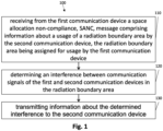
- Fig. 1 shows an example of a method 100 for a network entity.
- the method 100 for the network entity is for controlling a communication between a first communication device and a third communication device.
- the method 100 comprises receiving 110 from the first communication device a space allocation non-compliance, SANC, message comprising information about a usage of a radiation boundary area by a second communication device, the radiation boundary area being assigned for usage by the first communication device.
- the method 100 comprises determining 120 an interference between communication signals of the first and second communication devices in the radiation boundary area and transmitting 130 information about the determined interference to the second communication device. This way, the network entity can be informed by the first communication device about an interferer, e.g., the second communication device, of the first communication device.
- the network entity can perform measures for controlling the communication between the first communication device and the third communication device, e.g., by informing the second communication device about the interference caused.
- interfering communication occurring between the first communication device and the second communication device can be reduced or forbidden, e.g., by forbidding the second communication device to use the radiation boundary area with the same resource as the first communication device.
- the method 100 may be for improving a communication between the first communication and the third communication device by reducing interference with a communication signal of the second communication device.
- the network entity may be responsible to assign a spatial allocation, e.g., a radiation boundary area to each communication device in its own coverage area and/or transmission resources (e.g., belonging to a transmission parameter), such like frequency, time, radiation density for the radiation boundary area.
- a spatial allocation e.g., a radiation boundary area
- transmission resources e.g., belonging to a transmission parameter
- the network entity may be not capable to monitor a correct use of the assigned spatial resource and/or transmission resource.
- the network entity can receive information about a non-assigned usage of a spatial allocation and/or transmission resources from the first communication device. This way, the network entity can be enabled to maintain the resources of its own coverage area in an improved way, especially to minimize interference between different communication devices.
- the first/second/third communication device may communicate in a mobile communication system with the network entity, e.g., a base station.
- the network entity e.g., a base station.
- the first/second/third communication device and the network entity may communicate in/via a mobile communication system.
- the mobile communication system may comprise a plurality of transmission points and/or base stations operable to communicate radio signals with the first/second/third communication device.
- the mobile communication system may comprise the first/second/third communication device and the network entity.
- a network entity e.g., the network entity, can be located in the fixed or stationary part of the network or system.
- a network entity may correspond to a remote radio head, a transmission point, an access point, a macro cell, a small cell, a micro cell, a pico cell, a femto cell, a metro cell etc.
- the term small cell may refer to any cell smaller than a macro cell, e.g., a micro cell, a pico cell, a femto cell, or a metro cell.
- a femto cell is considered smaller than a pico cell, which is considered smaller than a micro cell.
- a network entity can be a wireless interface of a wired network, which enables transmission and reception of radio signals to a communication device.
- a radio signal may comply with radio signals as, for example, standardized by 3GPP or, generally, in line with one or more of the above listed systems.
- a network entity may correspond to a NodeB, an eNodeB, a BTS, an access point, etc.
- the mobile communication system may be cellular.
- the term cell refers to a coverage area of radio services provided by a transmission point, a remote unit, a remote head, a remote radio head, communication device, network entity or a NodeB, an eNodeB, respectively.
- the terms cell and base station may be used synonymously.
- a wireless communication device e.g., the first/second/third communication device, can be registered or associated with at least one cell (e.g., the network entity), e.g., it can be associated to a cell such that data can be exchanged between the network and the mobile in the coverage area of the associated cell using a dedicated channel or connection.
- the first/second/third communication device may be a device that is capable of communicating wirelessly.
- the first/second/third communication device may be a mobile communication device, e.g., a communication device that is suitable for being carried around by a user.
- the first/second/third communication device may be a User Terminal (UT) or User Equipment (UE) within the meaning of the respective communication standards being used for mobile communication.
- the first/second/third communication device may be a mobile phone, such as a smartphone, or another type of mobile communication device, such as a smartwatch, a laptop computer, a tablet computer, or autonomous augmented-reality glasses.
- the first/second/third communication device and the network entity may be configured to communicate in a cellular mobile communication system.
- the first/second/third communication device and the network entity may be configured to communicate in a cellular mobile communication system, for example in a Sub-6GHz-based cellular mobile communication system (covering frequency bands between 500 MHz and 6 GHz) or in a mmWave-based cellular mobile communication system (covering frequency bands between 20 GHz and 60 GHz).
- the first/second/third communication device and the network entity may be configured to communicate in a mobile communication system / cellular mobile communication system.
- the mobile communication system may, for example, correspond to one of the Third Generation Partnership Project (3GPP)-standardized mobile communication networks, where the term mobile communication system is used synonymously to mobile communication network.
- the mobile communication system may correspond to, for example, a 5th Generation system (5G), a Long-Term Evolution (LTE), an LTE-Advanced (LTE-A), High Speed Packet Access (HSPA), a Universal Mobile Telecommunication System (UMTS) or a UMTS Terrestrial Radio Access Network (UTRAN), an evolved-UTRAN (e-UTRAN), a Global System for Mobile communication (GSM) or Enhanced Data rates for GSM Evolution (EDGE) network, a GSM/EDGE Radio Access Network (GERAN), or mobile communication networks with different standards, for example, a Worldwide Inter-operability for Microwave Access (WIMAX) network IEEE 802.16, generally an Orthogonal Frequency Division Multiple Access (OFDMA) network, a Time Division Multiple Access (TDMA) network, a Code Division Multiple Access (CDMA) network, a Wide
- first/second/third communication device/network entity may be suitable for, or configured to, communicating/communicate via non-cellular communication systems, e.g., via a device-to-device vehicular communication system, e.g., according to the IEEE 802.11p standard (Institute of Electrical and Electronics Engineers standard 802.11p for vehicular communication) or via a wireless local area network (e.g., according to IEEE 802.11a, IEEE 802.11b, IEEE 802.11g, IEEE 802.11n, IEEE 802.11ac or IEEE 802.11ax, also known as Wi-Fi 1 through Wi-Fi 6(E)).
- IEEE 802.11p Institute of Electrical and Electronics Engineers standard 802.11p for vehicular communication
- a wireless local area network e.g., according to IEEE 802.11a, IEEE 802.11b, IEEE 802.11g, IEEE 802.11n, IEEE 802.11ac or IEEE 802.11ax, also known as Wi-Fi 1 through Wi-Fi 6(E)
- the first/second/third communication device and the network entity may be suitable for, or configured to, communicating/communicate in the frequency band between 5 GHz and 7.1 GHz, which covers communication in the 5 GHz band (for WiFi in the 5 GHz band), 5.9 GHz band (for vehicular communication according to the 802.11p standard) and between 5.9 GHz and 7.1 GHz (for WiFi in the 6 GHz band).
- a connection between the first/second/third communication device and the network entity and/or the first communication device and the second communication device may be a wireless connection, e.g., a mmWave-based connection over the mobile communication system (e.g., using carrier frequencies of at least 20 GHz) or may be performed at lower carrier frequencies, e.g., using carrier frequencies of at most 7.5 GHz.
- the wireless connection between the first/second/third communication device and the network entity may be initiated using the protocols of the mobile communication system, or using a short-range communication system, such as via a wireless local area network outlined above.
- first/second/third communication device and network entity and/or between first communication device, second communication device and third communication device occurs via the mobile communication system
- additional communication and/or alternatively communication e.g., the first, the second and/or the third communication device may be a vehicle or may be comprised by a vehicle
- D2D Device-to-Device
- Such communication may be carried out using the specifications of the vehicular communication system.
- D2D is direct communication between vehicles, also referred to as Vehicle-to-Vehicle communication (V2V) or Vehicle-to-Everything (V2X), car-to-car, Dedicated Short Range Communication (DSRC), respectively.
- V2V Vehicle-to-Vehicle communication
- V2X Vehicle-to-Everything
- DSRC Dedicated Short Range Communication
- technologies enabling such D2D-communication include 802.11p, 3GPP systems (4G, 5G, NR and beyond), etc.
- the radiation boundary area may be a space in the environment which is used for communication between communication devices.
- the radiation boundary area may be assigned to a specific communication device, e.g., the first communication device for transmitting and/or receiving a communication signal to/from a third communication device.
- a radiation energy density caused by the first communication device may be outside the radiation boundary area below a threshold, e.g., below a maximal allowed background radiation energy density which does not influence the communication of other communication devices outside the radiation boundary area.
- a radiation energy density of a transmission of the first communication device for communication with another communication device outside the radiation boundary area can be neglected.
- Receiving 110 the SANC message can be performed by any suitable message, e.g., by a broadcast message, groupcast message or unicast message.
- the information about the SANC can be transmitted in a desired way, e.g., using a broadcast message to transmit the information about the SANC to the network entity.
- the network entity is a vehicle or infrastructure (such like a traffic light, etc.) and the first communication device is another vehicle the information about the SANC may be transmitted via V2X communication.
- Determining 120 the interference between the communication signals may be performed by a processing unit of the network entity.
- the network entity may determine the interference of the communication signals of the first and the second communication device based on known information about a usage of a radiation boundary area.
- the network entity may maintain the radiation boundary area, e.g., a resource allocation for the radiation boundary area.
- the network entity may have information about a usage of the radiation boundary area by the first communication device and the second communication device.
- the network entity may determine 120 the interference based on information received from the first communication device. For example, the network entity may receive information about a position of the second communication device. Thus, the network entity can determine the interferer in an improved way. For example, the network entity may receive information about an intensity of the communication signal of the second communication device from the first communication device and may use this information for determining 120 the interference. This way, the determination of the interference can also be improved.
- Transmitting 130 the information about the determined interference may be performed by any suitable message, e.g., by a groupcast message or unicast message.
- the information may be transmitted 130 by use of a SANC response (SANCR) message.
- SANCR SANC response
- the SANCR message may only comprise information that the second communication device was reported as interferer. This way, the second communication device can be informed by the network entity in an eased way, that it negatively effects a communication of another communication device, e.g., the first communication device or the third communication device.
- the SANCR may comprise information about the interference between the communication signals of the first and the second communication device, a request for an authorization of the use of the radiation boundary area, information about an interfered another communication device, e.g. the first communication device, information about resource which could be used for usage of the radiation boundary area by the second communication device, etc.
- the network entity can inform the second communication device about required measures and/or can request required information from the second communication device to response to the first communication device, e.g., to purpose measures to the first communication device.
- the method 100 may further comprise obtaining a position of at least one of the first communication device or the second communication device. Further, determining the interference may be based on the obtained position.
- the network entity may receive a position of the second communication device via a SANC received from the first communication device and thus can determine a communication signal of the second communication signal. Since the network entity may know with which other communication device the second communication device communicates and/or which resource, e.g., wavelength, intensity, time, etc., may be used by the second communication device, a determination of the interference can be eased and/or improved.
- the network entity may receive information about the position of the first communication device and thus can determine a direction of departure of a communication signal of the first communication signal (since the network entity may know with which other communication device the first communication device may want to communicate). This way, a determination of the position of the interferer can be improved.
- the method 100 may further comprise requesting a measurement report from another communication device in at least one of a surrounding of the radiation boundary area or a surrounding of the position of the second communication device.
- the network entity may know the position of the first communication device and may request the measurement report from the other communication device, e.g., to improve information about the communication signal of the interferer, e.g., the second communication device. This way, the determination 120 of the interference can be improved, since the network entity may receive improved information about the communication signal of the interferer.
- the SANC message may comprise at least one of information about a position of the second communication device, information about a direction of arrival of the communication signal from the second communication device received at the first communication device or a radiation density of the communication signal of the second communication device received at the first communication device.
- the first communication device can provide information to the network entity, which may improve the determination 120 of the interference.
- the network entity can determine a direction of the interferer.
- the interference can be determined 120 in an improved way, since a signal intensity of the communication signal of the interferer may be known.
- the method may further comprise determining the position of the second communication device based on the SANC message.
- the position of the interferer e.g., the second communication device
- the position of the interferer may be determined based on the DoA of the communication signal of the second communication device.
- the determination of the interference can be increased based on the information received from the first communication device.
- the method may further comprise receiving from the second communication device information about a reason of the usage of the radiation boundary area and determining a usage priority of the radiation boundary area for at least one of the first communication device or the second communication device.
- the second communication device may have a reason for using the radiation boundary area, e.g., an owner of the second communication device may have paid to use the radiation boundary area.
- the second communication device can inform the network entity about the reason for usage.
- the network entity may reassign resources of the radiation boundary area, such that the second communication device can use the radiation boundary area.
- the network entity may inform the first communication device, that it has to stop its communication in the radiation boundary area, since the second communication device may be prioritized.
- the radiation boundary area may be based on a structured grid, dividing a space, e.g., a coverage area of the network entity, into a plurality of tiles.
- Each tile of the structured grid can represent a radiation boundary area.
- a plurality of tiles of the structured grid can represent a radiation boundary area.
- the structured grid can be hexagonal, triangular (geodesic grid), rectangular, or any shape that can uniformly fill the space.
- a shape of the radiation boundary area may depend on an antenna capability of the first communication device.
- Fig. 1 may comprise one or more optional additional features corresponding to one or more aspects mentioned in connection with the proposed concept or one or more examples described below (e.g., Fig. 2 - 5 ).
- Fig. 2 shows an example of a method 200 for a first communication device.
- the method 200 for the first communication device is for improving a usage of a radiation boundary area.
- the method 200 comprises detecting 210 a communication signal of a second communication device in a radiation boundary area assigned for usage to the first communication device, the communication signal of the second communication device interfering with a communication signal of the first communication device. Further, the method 200 comprises transmitting 220 to a network entity a space allocation non-compliance, SANC, message comprising information about a usage of a radiation boundary area by the second communication device.
- SANC space allocation non-compliance
- the first communication device can inform the network entity about an interferer of its own communication signal.
- the communication signal of the interferer may interfere with a communication signal received from another communication device, e.g., a third communication device, at the first communication device.
- the first communication device may receive the interfering communication signal from the interferer, which may decrease an intensity of the received communication signal from the other communication device.
- the first communication device may receive a decreased communication signal intensity from the third communication device due to the communication signal of the interferer, e.g., a second communication device.
- the first communication device may determine that an interferer, e.g., the second communication device, also radiates a communication signal in the same direction as the first communication device using the same radiation boundary area, which may affect receiving the communication signal from the first communication device at the third communication device.
- the first communication device can transmit information about the interferer to the network entity, without being directly affected in receiving a communication signal from the third communication device.
- the first communication device may communicate with a network entity as described above, e.g., with reference to Fig. 1 (e.g., the first communication device may be a counterpart to the network entity described with reference to Fig. 1 ).
- the first communication device may be UE, a vehicle, etc.
- the method 200 may further comprise detecting a direction of arrival of the communication signal of the second communication device and transmitting to the network entity information about the direction of arrival of the communication signal of the second communication device. This way, the first communication device can inform the network entity about a position or an area of/in which the interferer is positioned.
- the SANC message may comprise at least one of information about a position of the second communication device, information about a direction of arrival of the communication signal from the second communication device received at the first communication device or a radiation density of the communication signal of the second communication device received at the first communication device.
- the first communication device can transmit parameters, which can be used to determine an interferer and/or to determine an interference caused by the communication signal of the second communication device, to the network entity.
- Fig. 2 may comprise one or more optional additional features corresponding to one or more aspects mentioned in connection with the proposed concept or one or more examples described above ( Fig. 1 ) and/or below (e.g., Fig. 3 -5 ).
- Fig. 3 shows an example of a method 300 for a second communication device.
- the method 300 is for improving a usage of a radiation boundary area.
- the method 300 comprises receiving 310 from a network entity information about a determined interference between a communication signal of the second communication device and a communication signal of a first communication device in a radiation boundary area. Further, the method 300 comprises effecting 320 an adjustment of a communication of at least one of the first communication device or the second communication device based on the information about the determined interference.
- the second communication device may be an interferer of the first communication device described above, e.g., with respect to Fig. 2 .
- the second communication device may be reported by the first communication device using a SANC message to the network entity as described above, e.g., with reference to Fig. 1 .
- the interference between the communication signals of the first and the second communication device can be reduced or even omitted.
- a communication between the fist communication device and the third communication device can be controlled and/or improved.
- the method 300 may further comprise transmitting to the network entity information about a reason of the usage of the radiation boundary area. For example, a user of the second communication device may have paid to use a service instantly and thus the second communication device may be allowed to use the radiation boundary area. However, there may be a delay in informing the network entity about this fact, thus the first communication device may report the second communication device as interferer. Thus, the second communication device may inform the network entity about the purchased service. This may enable the network entity to reassign network resources for the radiation boundary area, e.g., to reassign resources from the first communication device to the second communication device. Further, the network entity may inform the first communication device about this reassignment. Thus, based on the SANC message of the first communication the network entity may either adjust a radiation characteristic of the first communication device, the second communication device or both.
- Fig. 3 may comprise one or more optional additional features corresponding to one or more aspects mentioned in connection with the proposed concept or one or more examples described above ( Fig. 1 - 2 ) and/or below (e.g., Fig. 4-5 ).
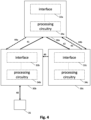
- Fig. 4 shows a block diagram of a mobile communication system.
- the mobile communication system comprises three apparatuses 30a, 30b, 30c.
- Each apparatus 30a, 30b, 30c comprises one or more interfaces 32a, 32b, 32c configured to communicate with a first communication device 30b, a second communication device 30c and/or network entity 30a.
- Each apparatus 30a, 30b, 30c further comprises processing circuitry 34a, 34b, 34c configured to control the one or more interfaces and to perform the method for the network entity 30a as described above (e.g., described with reference to Fig.1 ), the method for the first communication device 30b as described above (e.g., described with reference to Fig. 2 ) and/or the method for the second communication device 30c as described above (e.g., described with reference to Fig. 3 ).
- the network entity 30a may be communicatively coupled to the first communication device 30b and the second communication device 30c.
- the network entity 30a may receive 41 from the first communication device 30b a SANC message, which may inform the network entity 30a about an interferer 30c of the first communication device 30b, interfering the communication signal 48 of the first communication device with a communication signal 46.
- the first communication device 30b may communicate 48 with a third communication device 35, which could be interfered by the communication signal 46 of the second communication device 30c.
- the network entity 30a may determine an interference and may transmit 42 information about the determined interference to the second network entity 30c.
- the second communication device 30c may transmit 43 a message to inform the network entity 30a about a reason for usage of the radiation boundary area to the network entity 30a.
- the network entity 30a may transmit 44a, 44b a message to adjust a radiation characteristic to the first communication device 30b and/or the second communication device 30c. For example, the network entity 30a may reduce allocated resources for either one (the first communication device or the second communication device) or both communication devices.
- the apparatus 30b, 30c can be comprised by a vehicle.
- the vehicle may be a land vehicle, such a road vehicle, a car, an automobile, an off-road vehicle, a motor vehicle, a bus, a robo-taxi, a van, a truck or a lorry.
- the vehicle may be any other type of vehicle, such as a train, a subway train, a boat or a ship.
- the proposed concept may be applied to public transportation (trains, bus) and future means of mobility (e.g., robo-taxis).
- the respective one or more interfaces 32a, 32b, 32c are coupled to the respective processing circuitry 34a, 34b, 34c at the apparatus 30a, 30b, 30c.
- the processing circuitry 34a, 34b, 34c may be implemented using one or more processing units, one or more processing devices, any means for processing, such as a processor, a computer or a programmable hardware component being operable with accordingly adapted software. Similar, the described functions of the processing circuitry 34a, 34b, 34c may as well be implemented in software, which is then executed on one or more programmable hardware components.
- Such hardware components may comprise a general-purpose processor, a Digital Signal Processor (DSP), a micro-controller, etc.
- DSP Digital Signal Processor
- the processing circuitry 34a, 34b, 34c is capable of controlling the interface 32a, 32b, 32c, so that any data transfer that occurs over the interface and/or any interaction in which the interface may be involved may be controlled by the processing circuitry 34a, 34b, 34c.
- the apparatus 30a, 30b, 30c can be comprised by a vehicle.
- the vehicle may be a land vehicle, such a road vehicle, a car, an automobile, an off-road vehicle, a motor vehicle, a bus, a robo-taxi, a van, a truck or a lorry.
- the vehicle may be any other type of vehicle, such as a train, a subway train, a boat or a ship.
- the proposed concept may be applied to public transportation (trains, bus) and future means of mobility (e.g., robo-taxis).
- the apparatus 30a, 30b, 30c may comprise a memory and at least one processing circuitry 34a, 34b, 34c operably coupled to the memory and configured to perform the below mentioned method.
- the one or more interfaces 32a, 32b, 32c may correspond to any means for obtaining, receiving, transmitting or providing analog or digital signals or information, e.g., any connector, contact, pin, register, input port, output port, conductor, lane, etc. which allows providing or obtaining a signal or information.
- An interface may be wireless or wireline and it may be configured to communicate, e.g., transmit or receive signals, information with further internal or external components.
- the one or more interfaces 32a, 32b, 32c may comprise further components to enable communication between vehicles.
- Such components may include transceiver (transmitter and/or receiver) components, such as one or more Low-Noise Amplifiers (LNAs), one or more Power-Amplifiers (PAs), one or more duplexers, one or more diplexers, one or more filters or filter circuitry, one or more converters, one or more mixers, accordingly adapted radio frequency components, etc.
- LNAs Low-Noise Amplifiers
- PAs Power-Amplifiers
- duplexers one or more duplexers
- diplexers one or more filters or filter circuitry
- filters or filter circuitry one or more filters or filter circuitry
- converters one or more mixers, accordingly adapted radio frequency components, etc.
- Fig. 4 may comprise one or more optional additional features corresponding to one or more aspects mentioned in connection with the proposed concept or one or more examples described above ( Fig. 1 - 3 ) and/or below (e.g., Fig. 5 ).
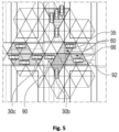
- Fig. 5 shows an example for a communication between a first communication device 90 and a third communication device 92.
- a spatial allocation of two different time-frequency resources (vertical hatching, horizontal hatching) is used to assign resources to the plurality of communication devices 30b, 30c, 35, 90, 92.
- a controlling base station e.g., the network entity as described with reference to Fig. 1 , may be responsible for determining the radiation boundary areas 60, 66 (see the connected hatched triangles).
- a radiation boundary area can be only one tile, or a plurality of tiles as shown for the radiation boundary areas 60, 66.
- transmission resources e.g., a radiation boundary area, a frequency, a time, a radiation density, etc.
- the base station may not recognize a change in the use of the radiation boundary area, caused by a communication device 30b, 30c, 35, 90, 92.
- the base station may be not capable to detect if a communication device 30b, 30c, 35, 90, 92 does use a not assigned spatial allocation constraint, e.g., a radiation boundary area, and/or another resource constraint, e.g., a frequency, a time, a radiation density, etc.
- a not assigned spatial allocation constraint e.g., a radiation boundary area
- another resource constraint e.g., a frequency, a time, a radiation density, etc.
- the communication devices 30b, 30c, 35 may use the same Time-Frequency (TF) resource with different space allocations 60 (vertical hatched space allocations).
- the communication devices 90, 92 may have a different TF resource with a different space allocation 66.
- the second communication device 30c may not comply with its space allocation and/or TF resource, as its communication signal may excess a radiation boundary in the radiation boundary area 60. This may cause an interference with the communication signal between the second 30b and a third communication device 35, which may decrease the communication between both communication devices 30b, 35.
- the first communication device 30b may inform the controlling base station about this fact, e.g., by transmitting a SANC.
- the first communication device 30b may perform a SANC detection to detect unwanted interference in its assigned radiation boundary area and/or TF resource.
- the first communication device 30b may be capable to determine the DoA of the communication signal of the second communication device 30c.
- the first communication device could transmit information about the DoA to the controlling base station, e.g., via a SANC message.
- the first communication device 30b may be not capable to determine the DoA.
- the first communication device may transmit a SANC message to the controlling base station.
- the SANC message may comprise at least information that an interferer was detected for a specific allocated TF resource.
- the SANC message may comprise a DoA (if detected), a measured radiation density, etc.
- the controlling base station may initiate an identification of the misbehaving communication device 30c. Further, the controlling base station may determine an interference caused by the misbehaving communication device 30c.
- the controlling base station may request a measurement report from another communication device in the area around the reported DoA, e.g., from the communication device 90. This might include only communication devices between the radiation boundary areas using the same TF resource.
- the controlling base station may request a measurement report from communication devices located within a certain area. For example, the certain area may be given by a radius calculated based on the reported radiation density of the second communication device 30c.
- the controlling base station may be able to estimate the location and identify the communication device involved with the SANC message, e.g., the interferer who caused the SANC message. To reduce the interference the controlling base station may inform the interferer, e.g., the second communication device 30c about the SANC message caused by the second communication device 30c. This way, the second communication device can adjust a radiation characteristic, e.g., by adjusting an antenna setting to reduce the interference.
- Fig. 5 may comprise one or more optional additional features corresponding to one or more aspects mentioned in connection with the proposed concept or one or more examples described above ( Fig. 1 - 4 ).
- Examples may be compliant to or even comprised in certain standard specifications, such as those specified by the 3GPP.
- Configuration information may for example be communicated using signaling radio bearers, e.g., by means of Radio Resource Control (RRC) messages, which are, for example, specified in the *.331 series of 3GPP as layer 3 control plane messages.
- RRC Radio Resource Control
- physical layer specification e.g., by means of Doppler Delay Resolutions and other physical layer specifications may also be affected by present embodiments, e.g., *.201, *.211, *.212, *.213, *.214, *.216 series in the 3GPP specifications.
- Examples may further be or relate to a (computer) program including a program code to execute one or more of the above methods when the program is executed on a computer, processor or other programmable hardware component.
- steps, operations or processes of different ones of the methods described above may also be executed by programmed computers, processors or other programmable hardware components.
- Examples may also cover program storage devices, such as digital data storage media, which are machine-, processor- or computer-readable and encode and/or contain machine-executable, processor-executable or computer-executable programs and instructions.
- Program storage devices may include or be digital storage devices, magnetic storage media such as magnetic disks and magnetic tapes, hard disk drives, or optically readable digital data storage media, for example.
- Other examples may also include computers, processors, control units, (field) programmable logic arrays ((F)PLAs), (field) programmable gate arrays ((F)PGAs), graphics processor units (GPU), application-specific integrated circuits (ASICs), integrated circuits (ICs) or system-on-a-chip (SoCs) systems programmed to execute the steps of the methods described above.
- FPLAs field programmable logic arrays
- F field) programmable gate arrays
- GPU graphics processor units
- ASICs application-specific integrated circuits
- ICs integrated circuits
- SoCs system-on-a-chip
- aspects described in relation to a device or system should also be understood as a description of the corresponding method.
- a block, device or functional aspect of the device or system may correspond to a feature, such as a method step, of the corresponding method.
- aspects described in relation to a method shall also be understood as a description of a corresponding block, a corresponding element, a property or a functional feature of a corresponding device or a corresponding system.
- a block, device or functional aspect of the device or system may correspond to a feature, such as a method step, of the corresponding method. Accordingly, aspects described in relation to a method shall also be understood as a description of a corresponding block, a corresponding element, a property or a functional feature of a corresponding device or a corresponding system.
Landscapes
- Engineering & Computer Science (AREA)
- Signal Processing (AREA)
- Computer Networks & Wireless Communication (AREA)
- Quality & Reliability (AREA)
- Physics & Mathematics (AREA)
- Electromagnetism (AREA)
- Mobile Radio Communication Systems (AREA)
Priority Applications (3)
| Application Number | Priority Date | Filing Date | Title |
|---|---|---|---|
| EP22184704.9A EP4307729A1 (fr) | 2022-07-13 | 2022-07-13 | Procédé pour une entité de réseau pour commander une communication, procédé pour un premier dispositif de communication, procédé pour un second dispositif de communication, appareil, véhicule et programme informatique |
| US18/350,820 US20240022949A1 (en) | 2022-07-13 | 2023-07-12 | Method for a network entity for controlling a communication, method for a first communication device, method for a second communication device, apparatus, vehicle and computer program |
| CN202310856307.0A CN117412255A (zh) | 2022-07-13 | 2023-07-13 | 网络实体的控制通信方法、第一通信装置的方法 |
Applications Claiming Priority (1)
| Application Number | Priority Date | Filing Date | Title |
|---|---|---|---|
| EP22184704.9A EP4307729A1 (fr) | 2022-07-13 | 2022-07-13 | Procédé pour une entité de réseau pour commander une communication, procédé pour un premier dispositif de communication, procédé pour un second dispositif de communication, appareil, véhicule et programme informatique |
Publications (1)
| Publication Number | Publication Date |
|---|---|
| EP4307729A1 true EP4307729A1 (fr) | 2024-01-17 |
Family
ID=82594813
Family Applications (1)
| Application Number | Title | Priority Date | Filing Date |
|---|---|---|---|
| EP22184704.9A Pending EP4307729A1 (fr) | 2022-07-13 | 2022-07-13 | Procédé pour une entité de réseau pour commander une communication, procédé pour un premier dispositif de communication, procédé pour un second dispositif de communication, appareil, véhicule et programme informatique |
Country Status (3)
| Country | Link |
|---|---|
| US (1) | US20240022949A1 (fr) |
| EP (1) | EP4307729A1 (fr) |
| CN (1) | CN117412255A (fr) |
Citations (6)
| Publication number | Priority date | Publication date | Assignee | Title |
|---|---|---|---|---|
| GB2543839A (en) | 2015-06-25 | 2017-05-03 | Airspan Networks Inc | Managing external interference in a wireless network |
| CN109660935A (zh) | 2018-11-27 | 2019-04-19 | 南通先进通信技术研究院有限公司 | 一种基站侧阵列天线系统的干扰定位方法 |
| WO2020146545A1 (fr) | 2019-01-08 | 2020-07-16 | Aero5G, Inc | Coordination d'interférence pour une communication de vol 5g |
| US20200296597A1 (en) * | 2019-03-12 | 2020-09-17 | Volkswagen Aktiengesellschaft | System, Vehicle, Apparatuses, Methods, and Computer Programs for User Equipment and for a Network Component in a Mobile Communication System |
| EP3796685A1 (fr) * | 2019-09-23 | 2021-03-24 | Volkswagen AG | Procédé, programme informatique, appareil et véhicule permettant de déterminer une représentation d'un environnement radio d'un émetteur-récepteur mobile |
| EP3813422A1 (fr) * | 2019-10-23 | 2021-04-28 | Volkswagen AG | Ajuster un diagramme d'antenne |
-
2022
- 2022-07-13 EP EP22184704.9A patent/EP4307729A1/fr active Pending
-
2023
- 2023-07-12 US US18/350,820 patent/US20240022949A1/en active Pending
- 2023-07-13 CN CN202310856307.0A patent/CN117412255A/zh active Pending
Patent Citations (6)
| Publication number | Priority date | Publication date | Assignee | Title |
|---|---|---|---|---|
| GB2543839A (en) | 2015-06-25 | 2017-05-03 | Airspan Networks Inc | Managing external interference in a wireless network |
| CN109660935A (zh) | 2018-11-27 | 2019-04-19 | 南通先进通信技术研究院有限公司 | 一种基站侧阵列天线系统的干扰定位方法 |
| WO2020146545A1 (fr) | 2019-01-08 | 2020-07-16 | Aero5G, Inc | Coordination d'interférence pour une communication de vol 5g |
| US20200296597A1 (en) * | 2019-03-12 | 2020-09-17 | Volkswagen Aktiengesellschaft | System, Vehicle, Apparatuses, Methods, and Computer Programs for User Equipment and for a Network Component in a Mobile Communication System |
| EP3796685A1 (fr) * | 2019-09-23 | 2021-03-24 | Volkswagen AG | Procédé, programme informatique, appareil et véhicule permettant de déterminer une représentation d'un environnement radio d'un émetteur-récepteur mobile |
| EP3813422A1 (fr) * | 2019-10-23 | 2021-04-28 | Volkswagen AG | Ajuster un diagramme d'antenne |
Also Published As
| Publication number | Publication date |
|---|---|
| US20240022949A1 (en) | 2024-01-18 |
| CN117412255A (zh) | 2024-01-16 |
Similar Documents
| Publication | Publication Date | Title |
|---|---|---|
| US20200064864A1 (en) | Vehicle, Apparatuses, Methods, and Computer Programs for a Mobile Transceiver and a Managing Mobile Transceiver Assigning Radio Resources | |
| US11503477B2 (en) | System, vehicle, apparatuses, methods, and computer programs for user equipment and for a network component in a mobile communication system | |
| EP4307729A1 (fr) | Procédé pour une entité de réseau pour commander une communication, procédé pour un premier dispositif de communication, procédé pour un second dispositif de communication, appareil, véhicule et programme informatique | |
| WO2022221995A1 (fr) | Procédé et appareil de mesure de canal, dispositif et support de stockage lisible | |
| US11751029B2 (en) | Vehicle, apparatus, method, and computer program for a vehicle in a mobile communication system | |
| EP4171138A1 (fr) | Procédé d'une entité de réseau pour commander une communication, procédé pour un dispositif de communication, appareil, véhicule et programme informatique | |
| EP4170918A1 (fr) | Procédés pour un dispositif de communication de commande d'une zone de limite de rayonnement, procédé d'une entité de réseau, appareil, véhicule et programme informatique | |
| EP4167495A1 (fr) | Procédé d'équipement d'utilisateur pour régler un paramètre de transmission, procédé pour un dispositif de communication, appareil, véhicule et programme informatique | |
| EP4312441A1 (fr) | Procédé pour une entité de réseau pour commander une communication, procédé pour un premier dispositif de communication, procédé pour un premier dispositif de communication, appareil, véhicule et programme informatique | |
| EP4192102A1 (fr) | Procédés permettant d'améliorer un transfert, appareil, véhicule et programme informatique | |
| US20230115781A1 (en) | Methods for communication devices for or adjusting a processing gain, apparatus, vehicle and computer program | |
| EP4106216A1 (fr) | Procédé pour un équipement utilisateur permettant de prévoir une dynamique de canal | |
| EP4187805A1 (fr) | Procédé permettant à un équipement d'utilisateur d'accroitre l'intensité d'un signal, procédé pour un dispositif de communication, appareil, véhicule et programme informatique | |
| US20230113523A1 (en) | Methods for user equipment for improving position information, apparatus, vehicle and computer program | |
| US20230122098A1 (en) | Method for user equipment for improving a handover list, method for a cell, apparatus, vehicle and computer program | |
| EP4106364A1 (fr) | Procédés pour un dispositif de communication pour une communication à ligne de visée, appareil, véhicule et programme informatique | |
| EP4117322A1 (fr) | Procédés pour un véhicule pour améliorer la communication via un canal radio, appareil, véhicule et programme informatique | |
| EP4116953A1 (fr) | Procédé pour véhicule communiquant avec un ou plusieurs autres véhicules, appareil, véhicule et programme informatique | |
| US20230122490A1 (en) | Methods for a relaying system for improving a handover list, method for a cell, apparatus, vehicle and computer program | |
| CN118104149A (zh) | 用于通信设备的用于控制辐射边界区域的方法、用于网络实体的方法、装置、车辆和计算机程序 |
Legal Events
| Date | Code | Title | Description |
|---|---|---|---|
| PUAI | Public reference made under article 153(3) epc to a published international application that has entered the european phase |
Free format text: ORIGINAL CODE: 0009012 |
|
| STAA | Information on the status of an ep patent application or granted ep patent |
Free format text: STATUS: REQUEST FOR EXAMINATION WAS MADE |
|
| 17P | Request for examination filed |
Effective date: 20230615 |
|
| AK | Designated contracting states |
Kind code of ref document: A1 Designated state(s): AL AT BE BG CH CY CZ DE DK EE ES FI FR GB GR HR HU IE IS IT LI LT LU LV MC MK MT NL NO PL PT RO RS SE SI SK SM TR |