EP4170918A1 - Procédés pour un dispositif de communication de commande d'une zone de limite de rayonnement, procédé d'une entité de réseau, appareil, véhicule et programme informatique - Google Patents
Procédés pour un dispositif de communication de commande d'une zone de limite de rayonnement, procédé d'une entité de réseau, appareil, véhicule et programme informatique Download PDFInfo
- Publication number
- EP4170918A1 EP4170918A1 EP21203418.5A EP21203418A EP4170918A1 EP 4170918 A1 EP4170918 A1 EP 4170918A1 EP 21203418 A EP21203418 A EP 21203418A EP 4170918 A1 EP4170918 A1 EP 4170918A1
- Authority
- EP
- European Patent Office
- Prior art keywords
- communication device
- boundary area
- radiation
- antenna system
- information
- Prior art date
- Legal status (The legal status is an assumption and is not a legal conclusion. Google has not performed a legal analysis and makes no representation as to the accuracy of the status listed.)
- Pending
Links
- 238000004891 communication Methods 0.000 title claims abstract description 244
- 230000005855 radiation Effects 0.000 title claims abstract description 240
- 238000000034 method Methods 0.000 title claims abstract description 82
- 238000004590 computer program Methods 0.000 title claims description 6
- 238000012545 processing Methods 0.000 claims description 20
- 238000013442 quality metrics Methods 0.000 claims description 13
- 238000010295 mobile communication Methods 0.000 description 28
- 230000006870 function Effects 0.000 description 9
- 230000005540 biological transmission Effects 0.000 description 6
- 230000001413 cellular effect Effects 0.000 description 6
- 230000001419 dependent effect Effects 0.000 description 5
- 230000008569 process Effects 0.000 description 5
- 108091006146 Channels Proteins 0.000 description 4
- 238000007493 shaping process Methods 0.000 description 4
- 238000013500 data storage Methods 0.000 description 3
- 238000001228 spectrum Methods 0.000 description 3
- 238000003491 array Methods 0.000 description 2
- 238000010586 diagram Methods 0.000 description 2
- 238000005516 engineering process Methods 0.000 description 2
- 238000003786 synthesis reaction Methods 0.000 description 2
- 229920000954 Polyglycolide Polymers 0.000 description 1
- 238000010521 absorption reaction Methods 0.000 description 1
- QVGXLLKOCUKJST-UHFFFAOYSA-N atomic oxygen Chemical compound [O] QVGXLLKOCUKJST-UHFFFAOYSA-N 0.000 description 1
- 230000015572 biosynthetic process Effects 0.000 description 1
- 238000004364 calculation method Methods 0.000 description 1
- 230000010267 cellular communication Effects 0.000 description 1
- 238000005352 clarification Methods 0.000 description 1
- 239000004020 conductor Substances 0.000 description 1
- 230000003247 decreasing effect Effects 0.000 description 1
- 238000011161 development Methods 0.000 description 1
- 230000018109 developmental process Effects 0.000 description 1
- 230000000694 effects Effects 0.000 description 1
- 239000011521 glass Substances 0.000 description 1
- 230000012447 hatching Effects 0.000 description 1
- 230000003993 interaction Effects 0.000 description 1
- 230000007774 longterm Effects 0.000 description 1
- 238000013507 mapping Methods 0.000 description 1
- 230000007246 mechanism Effects 0.000 description 1
- 238000012986 modification Methods 0.000 description 1
- 230000004048 modification Effects 0.000 description 1
- 229910052760 oxygen Inorganic materials 0.000 description 1
- 239000001301 oxygen Substances 0.000 description 1
- 229920000747 poly(lactic acid) Polymers 0.000 description 1
- 230000001902 propagating effect Effects 0.000 description 1
- 235000010409 propane-1,2-diol alginate Nutrition 0.000 description 1
- 238000013468 resource allocation Methods 0.000 description 1
- 230000011664 signaling Effects 0.000 description 1
- 238000012546 transfer Methods 0.000 description 1
- 230000009466 transformation Effects 0.000 description 1
- 238000002604 ultrasonography Methods 0.000 description 1
- XLYOFNOQVPJJNP-UHFFFAOYSA-N water Chemical compound O XLYOFNOQVPJJNP-UHFFFAOYSA-N 0.000 description 1
Images


Classifications
-
- H—ELECTRICITY
- H04—ELECTRIC COMMUNICATION TECHNIQUE
- H04B—TRANSMISSION
- H04B7/00—Radio transmission systems, i.e. using radiation field
- H04B7/02—Diversity systems; Multi-antenna system, i.e. transmission or reception using multiple antennas
- H04B7/04—Diversity systems; Multi-antenna system, i.e. transmission or reception using multiple antennas using two or more spaced independent antennas
- H04B7/06—Diversity systems; Multi-antenna system, i.e. transmission or reception using multiple antennas using two or more spaced independent antennas at the transmitting station
- H04B7/0686—Hybrid systems, i.e. switching and simultaneous transmission
- H04B7/0695—Hybrid systems, i.e. switching and simultaneous transmission using beam selection
-
- H—ELECTRICITY
- H04—ELECTRIC COMMUNICATION TECHNIQUE
- H04W—WIRELESS COMMUNICATION NETWORKS
- H04W16/00—Network planning, e.g. coverage or traffic planning tools; Network deployment, e.g. resource partitioning or cells structures
- H04W16/24—Cell structures
- H04W16/28—Cell structures using beam steering
-
- H—ELECTRICITY
- H01—ELECTRIC ELEMENTS
- H01Q—ANTENNAS, i.e. RADIO AERIALS
- H01Q1/00—Details of, or arrangements associated with, antennas
- H01Q1/12—Supports; Mounting means
- H01Q1/22—Supports; Mounting means by structural association with other equipment or articles
- H01Q1/24—Supports; Mounting means by structural association with other equipment or articles with receiving set
- H01Q1/241—Supports; Mounting means by structural association with other equipment or articles with receiving set used in mobile communications, e.g. GSM
- H01Q1/246—Supports; Mounting means by structural association with other equipment or articles with receiving set used in mobile communications, e.g. GSM specially adapted for base stations
-
- H—ELECTRICITY
- H04—ELECTRIC COMMUNICATION TECHNIQUE
- H04W—WIRELESS COMMUNICATION NETWORKS
- H04W76/00—Connection management
- H04W76/10—Connection setup
- H04W76/14—Direct-mode setup
Definitions
- Embodiments relate to methods for a communication device for controlling a radiation boundary area, a method for a network entity, an apparatus, a vehicle and a computer program, more particularly, but not exclusively, to a concept for controlling a communication between a communication device and another communication device, e.g., to adjust a radiation boundary area used by the communication devices for communication with the other communication device.
- 5G has brought increased attention to the automotive industry as a vertical manufacturer expected to leverage the most advanced features of the new generation of wireless communications.
- a wide range of spectrum possibilities (currently licensed up to the 28 GHz band - the first-ever Millimeter wave band for mobile use), enhanced support for high mobility scenarios and new mechanisms to guarantee and predict the experienced Quality of Service (QoS), have been established as key functions to support an increasingly connected transportation ecosystem.
- QoS Quality of Service
- the latest standard release (Rel. 16) has given support to Vehicle-to-Everything (V2X) communications with New Radio (NR) technology, allegedly allowing vehicles to make use of the same spectrum options, even for Vehicle-to-Vehicle (V2V) use cases.
- V2X Vehicle-to-Everything
- NR New Radio
- vehicles are also capable of communicating at frequencies above 6 GHz.
- these higher frequency bands are allocated at the mmWave range of the spectrum (30-300GHz).
- the use of higher frequency bands in communications implies propagating in a harsher channel, where the free-space path loss scales with ( f 2 ), and shading by obstacles and atmospheric effects (e.g., water vapor and oxygen absorption, or rain) take a non-negligible role.
- Services relying on higher frequency systems, with their inherently high channel-induced attenuation, might find challenging to deliver satisfactory QoS in some situations where signal power attenuation is increased, lowering the received Signal-to-Noise Ratio.
- 5G User Equipment is reliant on multi-antenna front ends to perform beamforming and focus the radiate power towards the intended transmitter/receiver. It is thus worth considering that vehicles may be equipped with an advanced multi-antenna system.
- US 2010 / 0246 377 A1 reveals a multiple-input multiple-output beamforming-based single carrier frequency division multiple access system.
- a fast Fourier transform is performed on transmission data to generate frequency domain data.
- the frequency domain data is mapped to assigned subcarriers.
- An inverse fast Fourier transform is performed on the transmit data mapped to the assigned subcarriers to generate time domain transmit data.
- the time domain transmit data is transmitted via antennas.
- an FFT is performed on the received data to generate frequency domain received data.
- a determination/generation of a radiation boundary area may depend on information provided by a communication device, e.g., an achievable antenna (system) radiation pattern. This way, space in an environment can be used more efficiently, e.g., by adjusting a radiation boundary area to an antenna (system) capability of a communication device, which shall use the radiation boundary area.
- a communication device e.g., an achievable antenna (system) radiation pattern.
- Examples provide a method for a communication device for controlling a radiation boundary area.
- the method comprises receiving information about a radiation boundary area and approximating at least one antenna system parameter of the communication device to adjust a radiation pattern of the antenna system to the radiation boundary area. Further, the method comprises configuring the antenna system to generate a radiation pattern to radiate into the radiation boundary area using the at least one antenna system parameter and transmitting information about the radiation pattern of the antenna system to a network entity.
- the network entity can be informed about a used antenna system pattern of the antenna system of the communication device and may determine a match between the radiation pattern and the radiation boundary area. This way, the network entity may be enabled to adjust the radiation boundary area to the radiation pattern of the communication device, e.g., if a deviation of the radiation pattern from the radiation boundary area exceeds a threshold.
- the method may further comprise generating a quality metric, which indicates a match of the radiation pattern with the radiation boundary area and transmitting the quality metric to the network entity. This way, the network entity can be informed about a match directly, which may omit a determination of the match by the network entity.
- the method may further comprise receiving a threshold for a maximal radiation energy density outside the radiation boundary area and configuring the antenna system to generate the radiation pattern such that it does not exceed the maximal radiation energy density outside the radiation boundary area. This way, it can be guaranteed that the radiation pattern of the communication device does not impacts other communication outside the radiation boundary area.
- approximating the at least one antenna system parameter may comprise determining Fourier Coefficients to adjust the radiation pattern of the antenna system to the radiation boundary area. This way, an improved calculation of the radiation pattern can be achieved.
- the method may further comprise determining information about an environment and transmitting the information about the environment to the network entity.
- the environment can be considered by the network entity for generating the radiation boundary area, e.g., a shielding of an obstacle may limit the radiation boundary area.
- Examples relates to a method for a communication device for controlling a radiation boundary area.
- the method comprises re transmitting information about an antenna system capability of the communication device to a network entity and receiving information about a radiation boundary area, wherein the information about the boundary area comprises information about at least one antenna system parameter of the communication device. Further, the method comprises configuring the antenna system with the received at least one antenna system parameter.
- the communication device may be enabled to configure its antenna system in an eased way. For example, configuring the antenna system can be based on the received at least one antenna system parameter and a determination of an antenna system parameter suitable for the radiation boundary area by the communication device can be avoided.
- Examples relate to a method for a network entity for improving a radiation boundary area.
- the method comprises receiving information from a communication device and generating a radiation boundary area for the communication of the communication device with another communication device based on the received information. Further, the method comprises transmitting information about the radiation boundary area to the communication device.
- the network entity can be informed by the communication device about, e.g., a restriction (e.g., an antenna system capability, an obstacle, a radiation pattern, etc.), which can be used to generate the radiation boundary area. This way, the radiation boundary area can be generated in an improved way.
- a restriction e.g., an antenna system capability, an obstacle, a radiation pattern, etc.
- the received information may comprise information about an antenna system capability of the communication device and the radiation boundary area may be generated based on the antenna system capability of the communication device. This way, the radiation boundary area can be adjusted to the antenna system capability of the communication device.
- the received information may comprise information about a radiation pattern of the communication device and the radiation boundary area may be generated based on the radiation pattern of the communication device. This way, the radiation boundary area can be adjusted to the radiation pattern of the communication device.
- the received information may comprise information about a movement speed of the communication device and the radiation boundary area may be generated based on the movement speed of the communication device. This way, the radiation boundary area can be adjusted to a dynamic situation.
- the received information may comprise information about an environment of the communication device and the radiation boundary area may be generated based on the environment of the communication device. This way, the radiation boundary area can be adjusted to the environment, e.g., to a radiopaque obstacle.
- Examples relate to a method for a communication device connected to another communication device for improving a device-to-device communication.
- the method comprises receiving from the other communication device a radiation boundary area to communicate with the other and/or a further communication device and communicating using the received radiation boundary area. This way, the communication device can be informed by the other communication device about the radiation boundary area even if the communication device is not communicatively connected to the (controlling) network entity.
- Examples further provide an apparatus, comprising one or more interfaces configured to communicate with a communication device or user equipment.
- the apparatus further comprises processing circuitry configured to control the one or more interfaces and to perform the method for user equipment and/or a communication device described above.
- Examples further provide a vehicle comprising the apparatus as described above.
- Examples further relate to a computer program having a program code for performing the method described above, when the computer program is executed on a computer, a processor, or a programmable hardware component.
- Fig. 1 shows an example of a method 100 for a communication device.
- the method 100 for controlling a radiation boundary area comprises receiving 110 information about a radiation boundary area and approximating 120 at least one antenna system parameter of the communication device to adjust a radiation pattern of the antenna system to the radiation boundary area. Further, the method 100 comprises configuring 130 the antenna system to generate a radiation pattern to radiate into the radiation boundary area using the at least one antenna system parameter and transmitting 140 information about the radiation pattern of the antenna system to a network entity.
- the communication device can inform the network entity about the radiation pattern, which may enable the network entity to improve a generation/determination of the radiation boundary area.
- the communication device may communicate in a mobile communication system with the network entity, e.g., a base station.
- the communication device and the network entity may communicate in/via a mobile communication system.
- the mobile communication system may comprise a plurality of transmission points and/or base stations operable to communicate radio signals with the communication device.
- the mobile communication system may comprise the communication device and the network entity.
- a network entity e.g., the network entity, can be located in the fixed or stationary part of the network or system.
- a network entity may correspond to a remote radio head, a transmission point, an access point, a macro cell, a small cell, a micro cell, a pico cell, a femto cell, a metro cell etc.
- the term small cell may refer to any cell smaller than a macro cell, e.g., a micro cell, a pico cell, a femto cell, or a metro cell.
- a femto cell is considered smaller than a pico cell, which is considered smaller than a micro cell.
- a network entity can be a wireless interface of a wired network, which enables transmission and reception of radio signals to a communication device.
- a radio signal may comply with radio signals as, for example, standardized by 3GPP or, generally, in line with one or more of the above listed systems.
- a network entity may correspond to a NodeB, an eNodeB, a BTS, an access point, etc.
- the mobile communication system may be cellular.
- the term cell refers to a coverage area of radio services provided by a transmission point, a remote unit, a remote head, a remote radio head, communication device, network entity or a NodeB, an eNodeB, respectively.
- the terms cell and base station may be used synonymously.
- a wireless communication device e.g., the communication device
- can be registered or associated with at least one cell e.g., the network entity
- it can be associated to a cell such that data can be exchanged between the network and the mobile in the coverage area of the associated cell using a dedicated channel, connection or connection.
- the communication device is a device that is capable of communicating wirelessly.
- the communication device may be a mobile communication device, e.g., a communication device that is suitable for being carried around by a user.
- the communication device may be a User Terminal (UT) or User Equipment (UE) within the meaning of the respective communication standards being used for mobile communication.
- the communication device may be a mobile phone, such as a smartphone, or another type of mobile communication device, such as a smartwatch, a laptop computer, a tablet computer, or autonomous augmented-reality glasses.
- the communication device and the network entity may be configured to communicate in a cellular mobile communication system.
- the communication device and the network entity may be configured to communicate in a cellular mobile communication system, for example in a Sub-6GHz-based cellular mobile communication system (covering frequency bands between 500 MHz and 6 GHz) or in a mmWave-based cellular mobile communication system (covering frequency bands between 20 GHz and 60 GHz).
- the communication device and the network entity may be configured to communicate in a mobile communication system / cellular mobile communication system.
- the mobile communication system may, for example, correspond to one of the Third Generation Partnership Project (3GPP)-standardized mobile communication networks, where the term mobile communication system is used synonymously to mobile communication network.
- 3GPP Third Generation Partnership Project
- the mobile communication system may correspond to, for example, a 5th Generation system (5G), a Long-Term Evolution (LTE), an LTE-Advanced (LTE-A), High Speed Packet Access (HSPA), a Universal Mobile Telecommunication System (UMTS) or a UMTS Terrestrial Radio Access Network (UTRAN), an evolved-UTRAN (e-UTRAN), a Global System for Mobile communication (GSM) or Enhanced Data rates for GSM Evolution (EDGE) network, a GSM/EDGE Radio Access Network (GERAN), or mobile communication networks with different standards, for example, a Worldwide Inter-operability for Microwave Access (WIMAX) network IEEE 802.16, generally an Orthogonal Frequency Division Multiple Access (OFDMA) network, a Time Division Multiple Access (TDMA) network, a Code Division Multiple Access (CDMA) network, a Wideband-CDMA (WCDMA) network, a Frequency Division Multiple Access (FDMA) network, a Spatial Division Multiple Access (SDMA) network, etc.
- 5G 5
- the communication device /network entity may be suitable for, or configured to, communicating/communicate via non-cellular communication systems, e.g., via a device-to-device vehicular communication system, e.g., according to the IEEE 802.11p standard (Institute of Electrical and Electronics Engineers standard 802.11p for vehicular communication) or via a wireless local area network (e.g., according to IEEE 802.11a, IEEE 802.11b, IEEE 802.11g, IEEE 802.11n, IEEE 802.11ac or IEEE 802.11ax, also known as Wi-Fi 1 through Wi-Fi 6(E)).
- IEEE 802.11p Institute of Electrical and Electronics Engineers standard 802.11p for vehicular communication
- a wireless local area network e.g., according to IEEE 802.11a, IEEE 802.11b, IEEE 802.11g, IEEE 802.11n, IEEE 802.11ac or IEEE 802.11ax, also known as Wi-Fi 1 through Wi-Fi 6(E)
- the communication device and the network entity may be suitable for, or configured to, communicating/communicate in the frequency band between 5 GHz and 7.1 GHz, which covers communication in the 5 GHz band (for WiFi in the 5 GHz band), 5.9 GHz band (for vehicular communication according to the 802.11p standard) and between 5.9 GHz and 7.1 GHz (for WiFi in the 6 GHz band).
- a connection between the communication device and the network entity may be a wireless connection, e.g., a mmWave-based connection over the mobile communication system (e.g., using carrier frequencies of at least 20 GHz) or may be performed at lower carrier frequencies, e.g., using carrier frequencies of at most 7.5 GHz.
- the wireless connection between the communication device and the network entity may be initiated using the protocols of the mobile communication system, or using a short-range communication system, such as via a wireless local area network outlined above.
- first/ second communication device and network entity and/or between first communication device and second communication device occurs via the mobile communication system
- additional communication and/or alternatively communication e.g., the first and the second communication device is a vehicle
- D2D Device-to-Device
- Such communication may be carried out using the specifications of the vehicular communication system.
- An example of D2D is direct communication between vehicles, also referred to as Vehicle-to-Vehicle communication (V2V) or Vehicle-to-Everything (V2X), car-to-car, Dedicated Short Range Communication (DSRC), respectively. Technologies enabling such D2D-communication include 802.11p, 3GPP systems (4G, 5G, NR and beyond), etc.
- the radiation boundary area may be a space in the environment which is used for communication by the communication device.
- a radiation energy density caused by the communication device may be outside the radiation boundary area below a threshold, e.g., below a maximal allowed background radiation energy density which does not interfere the communication of other communication devices.
- a radiation energy density of a transmission of the communication device used for communication (e.g., with another communication device) using the radiation boundary area can be neglected outside of the radiation boundary area.
- Receiving 110 the information about a radiation boundary area may be performed by any suitable message, e.g., by a broadcast message, groupcast message or unicast message.
- the information about a radiation boundary area can be received in a desired way, e.g., using a unicast message.
- Approximating 120 at least one antenna system parameter of the communication device to adjust a radiation pattern of the antenna system to the radiation boundary area may be performed by a processing unit of the communication device by calculating and/or loading data.
- the processing unit may calculate the at least one antenna system parameter to adjust the antenna system, e.g., based on Fourier Coefficients, for example.
- the processing unit may load data about the at least one antenna system parameter, e.g., from a data storage media, e.g., by use of a databank, a look-up table, etc.
- the communication device may consider an environment of its own to determine the radiation pattern.
- the radiation pattern is not solely a reflection of a possible achievable/adjustable radiation pattern, but rather a reflection of the real radiation pattern influenced, e.g., by obstacles such like other communication device, infrastructure, etc., especially inside or at an edge of the radiation boundary area.
- at an edge of the radiation boundary area may be a radiopaque structure arranged, e.g., a house.
- this radiopaque structure can be considered, e.g., a radiation energy density at this edge of the radiation boundary area can be chosen as necessary, since the radiopaque structure may block radiation at this edge and may ensure that the radiation energy density outside the radiation boundary area is below a threshold.
- Configuring 130 the antenna system to generate a radiation pattern to radiate into the radiation boundary area using the at least one antenna system parameter may be done by the processing unit.
- the radiation pattern may be generated in a way that a radiation energy density outside the radiation boundary area is not exceeded.
- the radiation pattern may be generated such that a minimal radiation energy density inside the boundary area can be achieved, especially for a predefined position in the radiation boundary area, e.g., for a position of another communication device.
- Transmitting 140 information about the radiation pattern of the antenna system to a network entity can be performed by any suitable message, e.g., by a broadcast message, groupcast message or unicast message.
- the information about the radiation pattern can be transmitted in a desired way, e.g., using a broadcast message to transmit the information about the radiation pattern to the network entity.
- the network entity is a vehicle and the communication device is another vehicle the information about the radiation pattern may be transmitted via V2X communication.
- the method 100 may further comprise generating a quality metric, which indicates a match of the radiation pattern with the radiation boundary area and transmitting the quality metric to the network entity.
- a control parameter for the quality of the radiation pattern with respect to the radiation boundary area can be determined.
- This control parameter can be transmitted 140 to the network entity (e.g., the control parameter may be the information about the radiation pattern transmitted 140 to the network entity) and may reduce data traffic and/or computational efforts on the side of the network entity.
- the quality metric may be independent of or depend on the environment of the communication device. For example, if the quality metric may be independent of the environment the quality metric may be a measure for the match of the radiation boundary area with an achievable/adjustable radiation pattern. For example, the quality metric may depend on the environment such that the quality metric may be a measure for the match of the real radiation pattern (e.g., influenced by obstacles) with the radiation boundary area.
- the quality metric may be independent of or depend on the environment of the communication device. For example, if the quality metric may be independent of the environment the quality metric may be a measure for the match of the radiation boundary area with an achievable/adjustable radiation pattern. For example, the quality metric may depend on the environment such that the quality metric may be a measure for the match of the real radiation pattern (e.g., influenced by obstacles) with the radiation boundary area.
- the method 100 may further comprise receiving a threshold for a maximal radiation energy density outside the radiation boundary area and configuring the antenna system to generate the radiation pattern such that it does not exceed the maximal radiation energy density outside the radiation boundary area.
- the threshold may be a maximal radiation energy density which does not influence communication between other communication devices outside the radiation boundary area.
- approximating 120 the at least one antenna system parameter may comprise determining Fourier Coefficients to adjust the radiation pattern of the antenna system to the radiation boundary area. This way, the at least one antenna system parameter can be determined by a well-known method, which may improve a usability for the network entity.
- the method 100 may further comprise determining information about an environment and transmitting the information about the environment to the network entity.
- the network entity may utilize the information about the environment to adjust the generation of the radiation boundary area.
- the communication device e.g., a vehicle
- the communication device may use a wide variety of on-board sensor data types, including radar sensor data and lidar sensor data, but also, e.g., vision-related sensors such as camera and IR sensors, as well as ultrasound sensors to determine the positions of the communication devices to determine information used to determine information for the predicted performance.
- the network entity may adjust a radiation boundary area such that an obstacle may be arranged outside the radiation boundary area.
- the network entity may adjust a radiation boundary area such that a radiopaque obstacle is arranged at an edge of the radiation boundary area. This way, the configuration of the antenna system of the communication device can be eased, since the radiation pattern at this edge can be neglected because it is blocked by the radiopaque obstacle from the outside of the radiation boundary area.
- Fig. 1 may comprise one or more optional additional features corresponding to one or more aspects mentioned in connection with the proposed concept or one or more examples described below (e.g., Fig. 2 - 8 ).
- Fig. 2 shows an example of another method 200 for a communication device.
- the method 200 for controlling a radiation boundary area comprises transmitting 210 information about an antenna system capability of the communication device to a network entity and receiving 220 information about a radiation boundary area.
- the information about the boundary area comprises information about at least one antenna system parameter of the communication device.
- the method 200 comprises configuring 230 the antenna system with the received at least one antenna system parameter. This way, the communication device can be enabled to utilize a radiation boundary area without being informed about the radiation boundary area, rather being informed about the at least one antenna system parameter, which may reduce a data traffic and/or may omit an approximation of the at least one antenna system parameter on the side of the communication device.
- the communication device may further receive information about a usage time of the at least one antenna system parameter.
- the network entity may inform the communication device that the at least one antenna system parameter can be used for a predefined time, e.g., 5s, 10s, 15s, etc.
- the predefined time may depend on the environment of the communication device and/or on a dynamic information about the environment (e.g., a movement of the communication device, a movement speed of a mobile obstacle, a planned route of the communication device, etc.).
- the communication device may further transmit information needed to determine the predefined time to the network entity (e.g., the communication device may transmit a movement speed of its own, a planned route of its own, etc.).
- Fig. 2 may comprise one or more optional additional features corresponding to one or more aspects mentioned in connection with the proposed concept or one or more examples described above ( Fig. 1 ) and/or below (e.g., Fig. 3 - 8 ).
- Fig. 3 shows an example of a method 300 for a network entity.
- the method 300 for improving a radiation boundary area comprises receiving 310 information from a communication device and generating 320 a radiation boundary area for the communication of the communication device with another communication device based on the received information. Further, the method 300 may further comprise transmitting 330 information about the radiation boundary area to the communication device. This way, the network entity may generate a radiation boundary area which is adjusted to the communication device.
- the information from the communication may comprise information about a radiation pattern which can be achieved/adjusted by an antenna system of the communication device, an antenna system capability, a quality metric, a combination thereof, etc.
- the network entity may be the counterpart of the communication device described with reference to Fig. 1 and Fig. 2 .
- the network entity may receive 310 from the communication device information about an achieved radiation pattern of the antenna system of the communication device.
- the radiation pattern may differ from an originally transmitted radiation boundary area and thus the network entity may adjust the radiation boundary area by generating 320 a (new/improved) radiation boundary area.
- This (new/improved) radiation boundary area may better match the achievable radiation pattern of the communication device and may be transmitted 330 to the communication device. This way, the radiation boundary area can be improved to the specific communication device, e.g., the antenna system of the communication device.
- the received information may comprise information about an antenna system capability of the communication device.
- the radiation boundary area may be generated based on the antenna system capability of the communication device. This way, the network entity can directly adjust the radiation boundary area to the antenna system capability of the communication device.
- the information about the antenna system capability may be information about a model/type of the communication device, which enables the network entity to determine the antenna system capability (e.g., using a databank). This way, data traffic can be reduced.
- the received information may comprise information about a radiation pattern of the communication device.
- the radiation boundary area may be generated based on the radiation pattern of the communication device. This way, the network entity can directly adjust the radiation boundary area to the radiation pattern of the communication device.
- the received information may comprise information about a movement speed of the communication device.
- the radiation boundary area may be generated based on the movement speed of the communication device. This way, the radiation boundary area can be adjusted, e.g., to increase a usage time, a reliability, etc. For example, for a communication with a lower movement speed a size of the radiation boundary area may be decreased in comparison to the size of the radiation boundary area for a communication device with a higher movement speed. For example, the size of the radiation boundary area may be increased for a moving communication device to increase a usage time of the radiation boundary area.
- the radiation boundary area may be generated based on a movement speed of the desired communication partner of the communication device using the radiation boundary area.
- the received information comprises information about an environment of the communication device.
- the radiation boundary area is generated based on the environment of the communication device. This way, the network entity can directly adjust the radiation boundary area to the radiation pattern of the communication device.
- Fig. 3 may comprise one or more optional additional features corresponding to one or more aspects mentioned in connection with the proposed concept or one or more examples described above ( Fig. 1 - 2 ) and/or below (e.g., Fig. 4-8 ).
- Fig. 4 shows an example of another method for a communication device.
- the method 400 for a communication device connected to another communication device for improving a device-to-device communication comprises receiving 410 from the other communication device a radiation boundary area to communicate with the other and/or a further communication device and communicating 420 using the received radiation boundary area. This way, the communication device can be informed about the radiation boundary area allocated by a (controlling) network entity without a need for a communicative connection to the network entity.
- Fig. 4 may comprise one or more optional additional features corresponding to one or more aspects mentioned in connection with the proposed concept or one or more examples described above ( Fig. 1 - 3 ) and/or below (e.g., Fig. 5-8 ).
- Fig. 5 shows a block diagram of a mobile communication system.
- the mobile communication system comprises three apparatuses 30a, 30b, 30c.
- Each apparatus 30a, 30b, 30c comprises one or more interfaces 32a, 32b, 32c configured to communicate with a communication device or user equipment.
- Each apparatus 30a, 30b, 30c further comprises processing circuitry 34a, 34b, 34c configured to control the one or more interfaces and to perform the methods for the (first) communication device 30b (connection established to the network entity) as described above (e.g., described with reference to Fig.1 and Fig. 2 ), the method for the network entity 30a as described above (e.g., described with reference to Fig. 3 ) and/or the method for the (second) communication device 30c (no connection established to the network entity) as described above (e.g., described with reference to Fig. 4 ).
- the apparatus 30a, 30b, 30c can be comprised by a vehicle.
- the vehicle may be a land vehicle, such a road vehicle, a car, an automobile, an off-road vehicle, a motor vehicle, a bus, a robo-taxi, a van, a truck or a lorry.
- the vehicle may be any other type of vehicle, such as a train, a subway train, a boat or a ship.
- the proposed concept may be applied to public transportation (trains, bus) and future means of mobility (e.g., robo-taxis).
- the network entity 30a may be communicatively coupled to the first communication device 30b.
- the network entity 30a may allocate a radiation boundary area to the first communication device 30b and may transmit 41 information about the allocated radiation boundary area to the first communication device 30b.
- the first communication device 30b may transmit 42 information about the allocated radiation boundary area to the second communication device 30c.
- the first communication device 30b and the second communication device 30c may communicate 44 with each other using the allocated radiation boundary area.
- the respective one or more interfaces 32a, 32b, 32c are coupled to the respective processing circuitry 34a, 34b, 34c at the apparatus 30a, 30b, 30c.
- the processing circuitry 34a, 34b, 34c may be implemented using one or more processing units, one or more processing devices, any means for processing, such as a processor, a computer or a programmable hardware component being operable with accordingly adapted software. Similar, the described functions of the processing circuitry 34a, 34b, 34c may as well be implemented in software, which is then executed on one or more programmable hardware components.
- Such hardware components may comprise a general-purpose processor, a Digital Signal Processor (DSP), a micro-controller, etc.
- DSP Digital Signal Processor
- the processing circuitry 34a, 34b, 34c is capable of controlling the interface 32a, 32b, 32c, so that any data transfer that occurs over the interface and/or any interaction in which the interface may be involved may be controlled by the processing circuitry 34a, 34b, 34c.
- the apparatus 30a, 30b, 30c can be comprised by a vehicle.
- the vehicle may be a land vehicle, such a road vehicle, a car, an automobile, an off-road vehicle, a motor vehicle, a bus, a robo-taxi, a van, a truck or a lorry.
- the vehicle may be any other type of vehicle, such as a train, a subway train, a boat or a ship.
- the proposed concept may be applied to public transportation (trains, bus) and future means of mobility (e.g., robo-taxis).
- the apparatus 30a, 30b, 30c may comprise a memory and at least one processing circuitry 34a, 34b, 34c operably coupled to the memory and configured to perform the below mentioned method.
- the one or more interfaces 32a, 32b, 32c may correspond to any means for obtaining, receiving, transmitting or providing analog or digital signals or information, e.g., any connector, contact, pin, register, input port, output port, conductor, lane, etc. which allows providing or obtaining a signal or information.
- An interface may be wireless or wireline and it may be configured to communicate, e.g., transmit or receive signals, information with further internal or external components.
- the one or more interfaces 32a, 32b, 32c may comprise further components to enable communication between vehicles.
- Such components may include transceiver (transmitter and/or receiver) components, such as one or more Low-Noise Amplifiers (LNAs), one or more Power-Amplifiers (PAs), one or more duplexers, one or more diplexers, one or more filters or filter circuitry, one or more converters, one or more mixers, accordingly adapted radio frequency components, etc.
- LNAs Low-Noise Amplifiers
- PAs Power-Amplifiers
- duplexers one or more duplexers
- diplexers one or more filters or filter circuitry
- filters or filter circuitry one or more filters or filter circuitry
- converters one or more mixers, accordingly adapted radio frequency components, etc.
- Fig. 5 may comprise one or more optional additional features corresponding to one or more aspects mentioned in connection with the proposed concept or one or more examples described above ( Fig. 1 - 4 ) and/or below (e.g., Fig. 6-8 ).
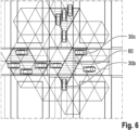
- Fig. 6 shows an example for communication between a plurality of communication devices 30b, 30c.
- a base station e.g., the network entity described with reference to Fig. 3
- D2D Device-to-Device
- the communication devices 30b, 30c may be equipped with multi-element antenna systems capable of shaping, steering and tuning the directivity/beamwidth of the radiation pattern that they communicate with. Further, the communication devices 30b, 30c may be equipped with M antenna system elements.
- the BS may allocate to each communication device 30b, 30c a radiation boundary area 60, e.g., a specific area in space based on an antenna footprint (or an angular region in space), determined by e.g., by power constraints, an antenna system capability, etc. Further the BS may allocate a time resource (a time frame/slot) for communication between two communication devices 30b, 30c using the radiation boundary area. Further, the BS may allocate a frequency resource (e.g., a channel/subchannel) for communication between two communication devices 30b, 30c using the radiation boundary area.
- a radiation boundary area 60 e.g., a specific area in space based on an antenna footprint (or an angular region in space), determined by e.g., by power constraints, an antenna system capability, etc. Further the BS may allocate a time resource (a time frame/slot) for communication between two communication devices 30b, 30c using the radiation boundary area. Further, the BS may allocate a frequency resource (e.g., a channel
- the (first) communication device 30b may receive an allocation in time, frequency and/or a space (e.g., a radiation boundary area 60) for a link intended to be established, e.g., to the other (second) communication device 30c.
- the information about the radiation boundary area (the allocation in space) (and/or a time resource, a frequency resource) may be transmitted to the communication device 30b.
- a power threshold may be transmitted with the information about the allocation in space.
- the power threshold in dBm should not be exceeded outside of the allocated space, e.g., the radiation boundary area 60.
- the communication device 30b may translate (information about) the allocated space into local coordinates and may perform variable transformation to represent the allocated space in electric angle variables.
- the communication device 30b may then take the allocated space as a constraint in antenna footprint.
- the constraint may be further used as an Array Factor Limit (AFL).
- the communication device 30b may perform an Inverse Discrete Fourier Transform (IDFT) of the AFL, to discretize the area as a Fourier series.
- This Fourier series (e.g., the Fourier Coefficients of the Fourier series) may be transmitted to the BS.
- the communication device 30b may perform beam-shaping by adjusting its antenna system. For example, the communication device 30b may take M (Fourier) coefficients from the Fourier series to recreate the AFL with the antenna system comprising the M antenna system elements.
- the communication device 30b may use the coefficients as antenna system weights. For example, the communication device 30b may tune the radiated power to comply with the transmitted power threshold. Further, the communication device 30b may share information related to the used beam-shaping and the targeted allocation within a message, e.g., a broadcast message. For example, the communication device may share a quality metric to indicate the extent to which the used beam-shaping complies with the allocation limit (e.g., a goodness of fit).
- a quality metric to indicate the extent to which the used beam-shaping complies with the allocation limit (e.g., a goodness of fit).
- the same time resource and/or frequency resource may be allocated for different communication devices (both unicast and groupcast) across a space, e.g., the coverage area of the BS, for different radiation boundary areas 60.
- the vertically hatched tiles represent the same time resource and/or frequency resource.
- Fig. 6 may comprise one or more optional additional features corresponding to one or more aspects mentioned in connection with the proposed concept or one or more examples described above ( Fig. 1 - 5 ) and/or below (e.g., Fig. 7-8 ).
- Fig. 7 shows examples of different patterns of a radiation boundary area.
- triangular grids which can be contained in hexagonal grids
- Hexagonal coordinates are customary in world mapping, e.g., maps for vehicle are based normally based on hexagons.
- different tile can be assigned by a network entity to a radiation boundary area.
- all tiles in a surrounding of the first communication device 30b e.g., a vehicle 30b, can be assigned to the radiation boundary area 60a. This way, an antenna system of the vehicle 30b may have an omnidirectional radiation pattern.
- the radiation boundary area 60b may comprise only certain tiles in a forward direction of the vehicle 30b, which can be realized, e.g., with a beam-based shape.
- the radiation boundary area 60c may comprise only elements on a side of the vehicle 30b, e.g., a right side, which can be achieved with a beam-shaped radiation pattern.
- Fig. 7 may comprise one or more optional additional features corresponding to one or more aspects mentioned in connection with the proposed concept or one or more examples described above ( Fig. 1 - 6 ) and/or below (e.g., Fig. 8 ).
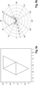
- Fig. 8 shows an example of a triangular grid-base radiation boundary area and an array factor limit representation.
- Fig. 8a shows an example representation of a triangular grid-based space allocation (radiation boundary area). Three triangles in space are allocated and represent the Array Factor Limit.
- Fig. 8b shows the array factor limit represented in polar coordinates (dashed line), together with a Fourier synthesis to comply with the space limitations (dotted line). As can be seen the Fourier syntheses matches the radiation boundary area in a proper way.
- Fig. 8 may comprise one or more optional additional features corresponding to one or more aspects mentioned in connection with the proposed concept or one or more examples described above ( Fig. 1 - 7 ).
- Examples may be compliant to or even comprised in certain standard specifications, such as those specified by the 3GPP.
- Configuration information may for example be communicated using signaling radio bearers, e.g., by means of Radio Resource Control (RRC) messages, which are, for example, specified in the *.331 series of 3GPP as layer 3 control plane messages.
- RRC Radio Resource Control
- physical layer specification e.g., by means of Doppler Delay Resolutions and other physical layer specifications may also be affected by present embodiments, e.g., *.201, *.211, *.212, *.213, *.214, *.216 series in the 3GPP specifications.
- Examples may further be or relate to a (computer) program including a program code to execute one or more of the above methods when the program is executed on a computer, processor or other programmable hardware component.
- steps, operations or processes of different ones of the methods described above may also be executed by programmed computers, processors or other programmable hardware components.
- Examples may also cover program storage devices, such as digital data storage media, which are machine-, processor- or computer-readable and encode and/or contain machine-executable, processor-executable or computer-executable programs and instructions.
- Program storage devices may include or be digital storage devices, magnetic storage media such as magnetic disks and magnetic tapes, hard disk drives, or optically readable digital data storage media, for example.
- Other examples may also include computers, processors, control units, (field) programmable logic arrays ((F)PLAs), (field) programmable gate arrays ((F)PGAs), graphics processor units (GPU), application-specific integrated circuits (ASICs), integrated circuits (ICs) or system-on-a-chip (SoCs) systems programmed to execute the steps of the methods described above.
- FPLAs field programmable logic arrays
- F field) programmable gate arrays
- GPU graphics processor units
- ASICs application-specific integrated circuits
- ICs integrated circuits
- SoCs system-on-a-chip
- aspects described in relation to a device or system should also be understood as a description of the corresponding method.
- a block, device or functional aspect of the device or system may correspond to a feature, such as a method step, of the corresponding method.
- aspects described in relation to a method shall also be understood as a description of a corresponding block, a corresponding element, a property or a functional feature of a corresponding device or a corresponding system.
- a block, device or functional aspect of the device or system may correspond to a feature, such as a method step, of the corresponding method. Accordingly, aspects described in relation to a method shall also be understood as a description of a corresponding block, a corresponding element, a property or a functional feature of a corresponding device or a corresponding system.
Priority Applications (2)
| Application Number | Priority Date | Filing Date | Title |
|---|---|---|---|
| EP21203418.5A EP4170918A1 (fr) | 2021-10-19 | 2021-10-19 | Procédés pour un dispositif de communication de commande d'une zone de limite de rayonnement, procédé d'une entité de réseau, appareil, véhicule et programme informatique |
| PCT/EP2022/079077 WO2023066987A1 (fr) | 2021-10-19 | 2022-10-19 | Procédés pour un dispositif de communication pour commander une zone de limite de rayonnement, procédé pour une entité de réseau, appareil, véhicule et programme informatique |
Applications Claiming Priority (1)
| Application Number | Priority Date | Filing Date | Title |
|---|---|---|---|
| EP21203418.5A EP4170918A1 (fr) | 2021-10-19 | 2021-10-19 | Procédés pour un dispositif de communication de commande d'une zone de limite de rayonnement, procédé d'une entité de réseau, appareil, véhicule et programme informatique |
Publications (1)
| Publication Number | Publication Date |
|---|---|
| EP4170918A1 true EP4170918A1 (fr) | 2023-04-26 |
Family
ID=78528633
Family Applications (1)
| Application Number | Title | Priority Date | Filing Date |
|---|---|---|---|
| EP21203418.5A Pending EP4170918A1 (fr) | 2021-10-19 | 2021-10-19 | Procédés pour un dispositif de communication de commande d'une zone de limite de rayonnement, procédé d'une entité de réseau, appareil, véhicule et programme informatique |
Country Status (2)
| Country | Link |
|---|---|
| EP (1) | EP4170918A1 (fr) |
| WO (1) | WO2023066987A1 (fr) |
Citations (6)
| Publication number | Priority date | Publication date | Assignee | Title |
|---|---|---|---|---|
| US20100246377A1 (en) | 2005-09-29 | 2010-09-30 | Interdigital Technology Corporation | Mimo beamforming-based single carrier frequency division multiple access system |
| US20130090126A1 (en) * | 2011-10-06 | 2013-04-11 | Futurewei Technologies, Inc. | System and Methods for Beam Shaping in a Self-Organizing network (SON) |
| US20130223487A1 (en) * | 2012-02-28 | 2013-08-29 | Fujitsu Limited | Wireless apparatus and wireless communication system |
| EP2892269A1 (fr) * | 2012-08-31 | 2015-07-08 | LG Electronics Inc. | Procédé et appareil pour virtualiser une antenne dans un système de communication sans fil |
| US20180352553A1 (en) * | 2014-07-15 | 2018-12-06 | Ruckus Wireless, Inc. | Antenna-Radiation-Pattern Selection for Reduced Interference |
| US20200037301A1 (en) * | 2019-08-09 | 2020-01-30 | Lg Electronics Inc. | Method for wireless communication of vehicle in autonomous driving system and apparatus thereof |
-
2021
- 2021-10-19 EP EP21203418.5A patent/EP4170918A1/fr active Pending
-
2022
- 2022-10-19 WO PCT/EP2022/079077 patent/WO2023066987A1/fr unknown
Patent Citations (6)
| Publication number | Priority date | Publication date | Assignee | Title |
|---|---|---|---|---|
| US20100246377A1 (en) | 2005-09-29 | 2010-09-30 | Interdigital Technology Corporation | Mimo beamforming-based single carrier frequency division multiple access system |
| US20130090126A1 (en) * | 2011-10-06 | 2013-04-11 | Futurewei Technologies, Inc. | System and Methods for Beam Shaping in a Self-Organizing network (SON) |
| US20130223487A1 (en) * | 2012-02-28 | 2013-08-29 | Fujitsu Limited | Wireless apparatus and wireless communication system |
| EP2892269A1 (fr) * | 2012-08-31 | 2015-07-08 | LG Electronics Inc. | Procédé et appareil pour virtualiser une antenne dans un système de communication sans fil |
| US20180352553A1 (en) * | 2014-07-15 | 2018-12-06 | Ruckus Wireless, Inc. | Antenna-Radiation-Pattern Selection for Reduced Interference |
| US20200037301A1 (en) * | 2019-08-09 | 2020-01-30 | Lg Electronics Inc. | Method for wireless communication of vehicle in autonomous driving system and apparatus thereof |
Also Published As
| Publication number | Publication date |
|---|---|
| WO2023066987A1 (fr) | 2023-04-27 |
Similar Documents
| Publication | Publication Date | Title |
|---|---|---|
| CN110582073B (zh) | 在移动通信系统中通信的车辆、装置、方法和计算机程序 | |
| CN111698663B (zh) | 系统、车辆、和用于用户装备和网络组件的装置、方法 | |
| CN110535678B (zh) | 配置消息接口的方法、装置和网络组件以及车辆 | |
| WO2020178124A1 (fr) | Véhicule, appareil, procédé, et programme informatique pour un véhicule dans un système de communications mobiles | |
| EP4170918A1 (fr) | Procédés pour un dispositif de communication de commande d'une zone de limite de rayonnement, procédé d'une entité de réseau, appareil, véhicule et programme informatique | |
| US11751029B2 (en) | Vehicle, apparatus, method, and computer program for a vehicle in a mobile communication system | |
| EP4171138A1 (fr) | Procédé d'une entité de réseau pour commander une communication, procédé pour un dispositif de communication, appareil, véhicule et programme informatique | |
| EP4307729A1 (fr) | Procédé pour une entité de réseau pour commander une communication, procédé pour un premier dispositif de communication, procédé pour un second dispositif de communication, appareil, véhicule et programme informatique | |
| EP4187805A1 (fr) | Procédé permettant à un équipement d'utilisateur d'accroitre l'intensité d'un signal, procédé pour un dispositif de communication, appareil, véhicule et programme informatique | |
| WO2021078510A1 (fr) | Ajustement d'un diagramme d'antenne | |
| EP4312441A1 (fr) | Procédé pour une entité de réseau pour commander une communication, procédé pour un premier dispositif de communication, procédé pour un premier dispositif de communication, appareil, véhicule et programme informatique | |
| EP4106216A1 (fr) | Procédé pour un équipement utilisateur permettant de prévoir une dynamique de canal | |
| US20230115781A1 (en) | Methods for communication devices for or adjusting a processing gain, apparatus, vehicle and computer program | |
| EP4167495A1 (fr) | Procédé d'équipement d'utilisateur pour régler un paramètre de transmission, procédé pour un dispositif de communication, appareil, véhicule et programme informatique | |
| US11984950B2 (en) | Vehicle, apparatus, method, and computer program for a vehicle in a mobile communication system | |
| US20230113523A1 (en) | Methods for user equipment for improving position information, apparatus, vehicle and computer program | |
| EP4106364A1 (fr) | Procédés pour un dispositif de communication pour une communication à ligne de visée, appareil, véhicule et programme informatique | |
| EP4192102A1 (fr) | Procédés permettant d'améliorer un transfert, appareil, véhicule et programme informatique | |
| US20230122098A1 (en) | Method for user equipment for improving a handover list, method for a cell, apparatus, vehicle and computer program | |
| EP4116953A1 (fr) | Procédé pour véhicule communiquant avec un ou plusieurs autres véhicules, appareil, véhicule et programme informatique | |
| EP4117322A1 (fr) | Procédés pour un véhicule pour améliorer la communication via un canal radio, appareil, véhicule et programme informatique |
Legal Events
| Date | Code | Title | Description |
|---|---|---|---|
| PUAI | Public reference made under article 153(3) epc to a published international application that has entered the european phase |
Free format text: ORIGINAL CODE: 0009012 |
|
| STAA | Information on the status of an ep patent application or granted ep patent |
Free format text: STATUS: REQUEST FOR EXAMINATION WAS MADE |
|
| 17P | Request for examination filed |
Effective date: 20220906 |
|
| AK | Designated contracting states |
Kind code of ref document: A1 Designated state(s): AL AT BE BG CH CY CZ DE DK EE ES FI FR GB GR HR HU IE IS IT LI LT LU LV MC MK MT NL NO PL PT RO RS SE SI SK SM TR |
|
| STAA | Information on the status of an ep patent application or granted ep patent |
Free format text: STATUS: EXAMINATION IS IN PROGRESS |
|
| 17Q | First examination report despatched |
Effective date: 20240409 |