EP4306937B1 - Wassertrübungsbewertung mit bildsensor - Google Patents
Wassertrübungsbewertung mit bildsensor Download PDFInfo
- Publication number
- EP4306937B1 EP4306937B1 EP23185061.1A EP23185061A EP4306937B1 EP 4306937 B1 EP4306937 B1 EP 4306937B1 EP 23185061 A EP23185061 A EP 23185061A EP 4306937 B1 EP4306937 B1 EP 4306937B1
- Authority
- EP
- European Patent Office
- Prior art keywords
- water
- turbidity
- images
- distances
- image
- Prior art date
- Legal status (The legal status is an assumption and is not a legal conclusion. Google has not performed a legal analysis and makes no representation as to the accuracy of the status listed.)
- Active
Links
Images




Classifications
-
- G—PHYSICS
- G01—MEASURING; TESTING
- G01N—INVESTIGATING OR ANALYSING MATERIALS BY DETERMINING THEIR CHEMICAL OR PHYSICAL PROPERTIES
- G01N21/00—Investigating or analysing materials by the use of optical means, i.e. using sub-millimetre waves, infrared, visible or ultraviolet light
- G01N21/17—Systems in which incident light is modified in accordance with the properties of the material investigated
- G01N21/25—Colour; Spectral properties, i.e. comparison of effect of material on the light at two or more different wavelengths or wavelength bands
-
- G—PHYSICS
- G01—MEASURING; TESTING
- G01N—INVESTIGATING OR ANALYSING MATERIALS BY DETERMINING THEIR CHEMICAL OR PHYSICAL PROPERTIES
- G01N1/00—Sampling; Preparing specimens for investigation
-
- G—PHYSICS
- G01—MEASURING; TESTING
- G01N—INVESTIGATING OR ANALYSING MATERIALS BY DETERMINING THEIR CHEMICAL OR PHYSICAL PROPERTIES
- G01N21/00—Investigating or analysing materials by the use of optical means, i.e. using sub-millimetre waves, infrared, visible or ultraviolet light
- G01N21/17—Systems in which incident light is modified in accordance with the properties of the material investigated
- G01N21/47—Scattering, i.e. diffuse reflection
- G01N21/49—Scattering, i.e. diffuse reflection within a body or fluid
- G01N21/53—Scattering, i.e. diffuse reflection within a body or fluid within a flowing fluid, e.g. smoke
-
- G—PHYSICS
- G01—MEASURING; TESTING
- G01N—INVESTIGATING OR ANALYSING MATERIALS BY DETERMINING THEIR CHEMICAL OR PHYSICAL PROPERTIES
- G01N21/00—Investigating or analysing materials by the use of optical means, i.e. using sub-millimetre waves, infrared, visible or ultraviolet light
- G01N21/17—Systems in which incident light is modified in accordance with the properties of the material investigated
- G01N21/59—Transmissivity
-
- G—PHYSICS
- G01—MEASURING; TESTING
- G01N—INVESTIGATING OR ANALYSING MATERIALS BY DETERMINING THEIR CHEMICAL OR PHYSICAL PROPERTIES
- G01N1/00—Sampling; Preparing specimens for investigation
- G01N1/02—Devices for withdrawing samples
- G01N1/22—Devices for withdrawing samples in the gaseous state
- G01N1/24—Suction devices
-
- G—PHYSICS
- G01—MEASURING; TESTING
- G01N—INVESTIGATING OR ANALYSING MATERIALS BY DETERMINING THEIR CHEMICAL OR PHYSICAL PROPERTIES
- G01N15/00—Investigating characteristics of particles; Investigating permeability, pore-volume or surface-area of porous materials
- G01N15/06—Investigating concentration of particle suspensions
-
- G—PHYSICS
- G01—MEASURING; TESTING
- G01N—INVESTIGATING OR ANALYSING MATERIALS BY DETERMINING THEIR CHEMICAL OR PHYSICAL PROPERTIES
- G01N21/00—Investigating or analysing materials by the use of optical means, i.e. using sub-millimetre waves, infrared, visible or ultraviolet light
- G01N21/17—Systems in which incident light is modified in accordance with the properties of the material investigated
- G01N21/47—Scattering, i.e. diffuse reflection
- G01N21/49—Scattering, i.e. diffuse reflection within a body or fluid
-
- G—PHYSICS
- G01—MEASURING; TESTING
- G01N—INVESTIGATING OR ANALYSING MATERIALS BY DETERMINING THEIR CHEMICAL OR PHYSICAL PROPERTIES
- G01N21/00—Investigating or analysing materials by the use of optical means, i.e. using sub-millimetre waves, infrared, visible or ultraviolet light
- G01N21/84—Systems specially adapted for particular applications
-
- G—PHYSICS
- G01—MEASURING; TESTING
- G01N—INVESTIGATING OR ANALYSING MATERIALS BY DETERMINING THEIR CHEMICAL OR PHYSICAL PROPERTIES
- G01N33/00—Investigating or analysing materials by specific methods not covered by groups G01N1/00 - G01N31/00
- G01N33/18—Water
-
- G—PHYSICS
- G01—MEASURING; TESTING
- G01N—INVESTIGATING OR ANALYSING MATERIALS BY DETERMINING THEIR CHEMICAL OR PHYSICAL PROPERTIES
- G01N21/00—Investigating or analysing materials by the use of optical means, i.e. using sub-millimetre waves, infrared, visible or ultraviolet light
- G01N21/01—Arrangements or apparatus for facilitating the optical investigation
- G01N2021/0106—General arrangement of respective parts
- G01N2021/0118—Apparatus with remote processing
-
- G—PHYSICS
- G01—MEASURING; TESTING
- G01N—INVESTIGATING OR ANALYSING MATERIALS BY DETERMINING THEIR CHEMICAL OR PHYSICAL PROPERTIES
- G01N21/00—Investigating or analysing materials by the use of optical means, i.e. using sub-millimetre waves, infrared, visible or ultraviolet light
- G01N21/17—Systems in which incident light is modified in accordance with the properties of the material investigated
- G01N21/47—Scattering, i.e. diffuse reflection
- G01N21/49—Scattering, i.e. diffuse reflection within a body or fluid
- G01N21/53—Scattering, i.e. diffuse reflection within a body or fluid within a flowing fluid, e.g. smoke
- G01N21/534—Scattering, i.e. diffuse reflection within a body or fluid within a flowing fluid, e.g. smoke by measuring transmission alone, i.e. determining opacity
-
- G—PHYSICS
- G01—MEASURING; TESTING
- G01N—INVESTIGATING OR ANALYSING MATERIALS BY DETERMINING THEIR CHEMICAL OR PHYSICAL PROPERTIES
- G01N21/00—Investigating or analysing materials by the use of optical means, i.e. using sub-millimetre waves, infrared, visible or ultraviolet light
- G01N21/84—Systems specially adapted for particular applications
- G01N21/88—Investigating the presence of flaws or contamination
- G01N21/94—Investigating contamination, e.g. dust
-
- G—PHYSICS
- G01—MEASURING; TESTING
- G01N—INVESTIGATING OR ANALYSING MATERIALS BY DETERMINING THEIR CHEMICAL OR PHYSICAL PROPERTIES
- G01N2201/00—Features of devices classified in G01N21/00
- G01N2201/02—Mechanical
- G01N2201/021—Special mounting in general
- G01N2201/0218—Submersible, submarine
Definitions
- the present invention relates to evaluating turbidity of water according to a method and system as set out in the appended set of claims.
- Ensuring high water quality, cleanliness and purity in artificial water bodies such as, for example, swimming pools, reservoirs, fountains, and/or the like may be highly desired and typically essential primarily for safety, health and/or hygiene related concerns.
- water clarity may also significantly affect user experience of people using a swimming pool.
- underwater visibility may be significantly degraded when the water is not very clean.
- foul water may cause the users to become highly concerned about hygiene conditions of the pool and may deter them from using it.
- underwater visibility may be extremely low which may lead to safety risks for people using a swimming pool since people in distress in the pool, for example, drowning, experiencing a seizure, having a heart attack and/or the like may not be seen.
- Turbidity of the water may constitute a major indicator of water quality and/or chemical balance since it is an indication of the amount of particles accumulated in the water and may be thus used to quantify the degree of cloudiness and/or clarity of the water.
- These small suspended particles of soil, algae or other materials in the microscopic size range to about one millimeter are often invisible to the naked eye and can be introduced from a variety of sources including air pollution, dirt, pollen, bathers, source water, algae, microbial organisms to name just a few.
- Low turbidity of the water may be therefore highly indicative of clean and/or chemically balanced water, and in contrast, high turbidity may indicate of foul and/or chemically unbalanced water.
- WO Application Publication No. WO2017175261 describes a turbidity detection apparatus which is provided with: a measuring member that has a dark area and a bright area; a camera that generates image data by photographing the dark area and the bright area of the measuring member through a liquid; and a turbidity detection unit that detects turbidity on the basis of image information about the dark area in the image data and image information about the bright area in the image data.
- the bright area of the measuring member has a higher brightness than the dark area.
- the turbidity detection apparatus can detect the turbidity of a liquid by means of a simple configuration.
- a method of evaluating water turbidity using image data comprising using one or more processors for:
- a system for evaluating water turbidity using image data comprising one or more processors configured to execute a code.
- the code comprising:
- the water is swimming pool water.
- the one or more actions are members of a group consisting of: transmitting one or more alert message, and/or inducing operation of water cleaning equipment in case the turbidity exceeds a predefined threshold.
- turbidity of the water is evaluated based on one or more fitting functions adapted to approximate distribution of the maximal intensity changes mapped with respect to the distances from the one or more objects.
- y the respective maximal intensity change calculated for each of the plurality of images which correspond thus corresponding to one of the plurality of distances x
- a is a largest maximal intensity change identified in the one or more gradient lines in all of the images
- b is the estimated turbidity
- the turbidity of the water is evaluated using one or more machine learning (ML) models trained to map images of the one or more objects from the plurality of distances to respective turbidity values.
- ML machine learning
- the one or more trained ML models are trained using a plurality of labeled training images depicting the one or more objects from a plurality of distances.
- a label of each of the plurality of labeled training images is indicative of a distance from which the respective training image is captured and a measured turbidity value.
- the one or more objects are detected using one or more visual analysis algorithms applied to analyze the plurality of images.
- one or more of the plurality of images are converted to a plurality of respective greyscale images before calculating the luma value for each of the plurality of pixels.
- the distance to the one or more object is calculated using one or more distance measurement device.
- the distance to the one or more objects is calculated based on one or more known dimensions of the one or more objects extracted from a respective image.
- the one or more gradient lines are members of a group consisting of: a horizontal line, a vertical line, a diagonal line, and a curved line.
- the gradient line selected for calculating the intensity change comprises a plurality of pixels with gradually increasing or gradually decreasing luma value.
- each of the plurality of segments comprises a predefined number of pixels of the one or more images.
- the turbidity of the water based is evaluated based on a peak of the histogram.
- the turbidity of the water based is evaluated based on a Weibull distribution derived from the histogram.
- Implementation of the method and/or system of embodiments of the invention can involve performing or completing selected tasks automatically. Moreover, according to actual instrumentation and equipment of embodiments of the method and/or system of the invention, several selected tasks could be implemented by hardware, by software or by firmware or by a combination thereof using an operating system.
- a data processor such as a computing platform for executing a plurality of instructions.
- the data processor includes a volatile memory for storing instructions and/or data and/or a non-volatile storage, for example, a magnetic hard-disk and/or removable media, for storing instructions and/or data.
- a network connection is provided as well.
- a display and/or a user input device such as a keyboard or mouse are optionally provided as well.
- methods, systems and computer program products for evaluating (estimating) water turbidity based on visual analysis of images captured underwater, in particular, based on distribution of intensity (brightness, luminance) of pixels in the images depicting objects and/or patterns submerged in the water.
- This visual analysis based water turbidly evaluation takes advantage of the fact that brightness changes (differences) in pixels portraying a submerged object may be highly indicative of the water turbidly, in particular, the larger the brightness change, the lower is the turbidity of the water, and vice versa, the smaller the brightness change, the higher is turbidity of the water.
- visual analysis may only apply for cases where there is a change in the brightness of the pixels portraying submerged object(s) and may be therefore significantly less efficient and possibly even impractical in case of no such brightness change, for example, due to excessive turbidity.
- a plurality of images may be captured underwater by one or more imaging sensors (e.g., camera, video camera, Infrared camera, etc.) deployed in a body of water, in particular a manmade (artificial) body of water, for example, a swimming pool, a water reservoir, a fountain, and/or the like, collectively designated water pool herein after.
- the imaging sensor(s) may be statically deployed in the water pool (e.g. pool wall) and/or mounted on one or more pool water platforms, such as pool robot cleaner, skimmer, buoyed and/or the like which may dynamically move in the water pool.
- the images captured in the water pool may depict one or more objects and/or patterns which are at least partially submerged in the water, for example, a lamp, a buoy, a pattern marked on a submerged surface (e.g. wall, floor, panel, board, etc.) and/or the like. While the objects may be fully submerged in the water and/or partially submerged, for brevity, such objects are designated submerged objects herein after.
- the plurality of images portraying the submerged object(s) may be captured for a plurality of distances from the submerged object(s), i.e., the images are captured by imaging sensor(s) located at a plurality of different distances from the submerged object(s).
- the images may be analyzed and processed to identify one or more of the submerged object(s) and further to correlate between common object(s) in images depicting the submerged object(s) from at least some of the plurality of distances.
- one or more filters for example, a noise filter and/or the like may be applied to one or more of the images to improve the images, for example, increase quality, sharpness, uniformity and/or the like.
- one or more of the images may be converted to greyscale format in attempt to improve their brightness (luma) representation.
- One or more images depicting the submerged object(s) from each of the distances may be analyzed to select one or more lines crossing the submerged object(s).
- the line(s) selected in each image may be a gradient line comprising a plurality of pixels having gradually increasing or gradually decreasing brightness, i.e., gradually increasing or gradually decreasing luma values.
- a respective maximal brightness change may be calculated for each of the distances.
- the maximal brightness change calculated for the pixels along the gradient line(s) selected in the image(s) captured from each of the distances may express the different between the highest luma value and the lowest luma value of the pixels along the gradient line.
- Turbidity of the water in the water pool which may be expressed, for example, in terms of Nephelometric Turbidity Units (NTU), may be evaluated and/or estimated using one or more methods, techniques and/or algorithms based on mapping of the maximal brightness changes to their corresponding distances.
- NTU Nephelometric Turbidity Units
- one or more fitting functions may be applied to fit on a distribution of the maximal brightness changes with respect to their corresponding distances.
- Each fitting function may comprise one or more turbidity related parameters which may be searched, selected, altered and/or the like to optimize a fit of the fitting function on the distribution of the maximal brightness changes.
- the water turbidity may be thus calculated, derived, evaluated, estimated and/or otherwise determined based on the turbidity related parameter(s) yielding best (optimal) fit over the maximal brightness changes distribution.
- the water turbidity may be evaluated using one or more Machine Learning (ML) models trained to estimate and/or predict a water turbidity based on the images of the submerged object(s) captured from the plurality of distances.
- the ML model(s) may be trained in one or more supervised training sessions using a plurality of labeled training images of the submerged object(s) where the label of each training image indicates the distance from the submerged object and a turbidity value indicating the actual turbidity level of the water in the water pool.
- the ML model(s) may be trained with images of the submerged object(s) captured in a plurality of different conditions (e.g., illumination, etc.), view angels and/or the like.
- the ML model(s) may be further trained online, post deployment.
- the water turbidity may be evaluated and/or estimated based on Standard Deviation (STD) of the intensity of pixels in images depicting one or more varying color patterns marked, formed, embedded and/or otherwise present on one or more surfaces of the water pool, for example, a circumferential wall, the floor, and/or part thereof.
- STD Standard Deviation
- One or more images depicting one or more varying color patterns identified underwater in a water pool may be each divided to a plurality of segments of equal size.
- the luma value may be calculated for each of the pixels in each of the segments, or at least the segments portraying the varying color pattern, and a brightness STD may be computed for each of the segments based on the luma values of the pixels of the respective segment.
- a histogram may be created based on an inverse value of the brightness STD values of the segments, i.e., based on 1/STD of each of the segments.
- a plurality of histograms may be carpeted based on the brightness STD calculated for the segments of a plurality of images depicting the varying color pattern(s) and an aggregated histogram may be created by aggregating, for example, summing the histograms created for the plurality of images.
- the turbidity of the water in the water pool may be then evaluated, estimated, calculated, derived and/or otherwise determined using one or more methods, functions and/or algorithms based on the histogram or optionally on the aggregated histogram if exists.
- the water turbidity may be evaluated according to a peak of the histogram.
- the water turbidity may be evaluated according to one or more parameters of a Weibull distribution generated based on the histogram.
- One or more actions may be initiated based on the evaluated water turbidity, specifically, in case the evaluated turbidity exceeds one or more threshold values and one or more actions should be taken to treat the water.
- one or more alert message may be transmitted to one or more maintenance personnel and/or automated systems which may take one or more actions to treat the water in case of high turbidity, for example, circulate the water through one or more filtering systems, dispose one or more materials (e.g. chlorine) into the water, replace the water or part thereof and/or the like.
- materials e.g. chlorine
- Evaluating and/or estimating the turbidity of water in a water pool based on visual analysis applied for calculate the brightens distribution of image pixels depicting submerged objects and/or patterns may present significant benefits and advantages compared to currently existing methods and system for measuring water turbidity.
- evaluating water turbidity based on visual analysis may require only very simple, low cost and highly accessible imaging devices thus significantly reducing cost, complexity, and/or maintenance of the evaluation system.
- the calculation of the intensity distribution across the submerged objects and/or patterns may be very simple thus significantly reducing the computing resources compared to the complex chemical measurement and composition analysis.
- the water turbidity evaluation system and/or engine may be integrated in existing water platforms, for example, water treatment, cleaning and/or purifying systems and/or robots already deployed and used in a plurality of water pools, for example, public swimming pools, private swimming pools, water reservoirs, city fountains and/or the like.
- existing water platforms may be already equipped with such imaging sensors which may be configured to capture to images used to evaluate the water turbidity. This availability of the imaging sensor(s) may further simplify deployment of the water turbidity evaluation system which may increase its adoption and use.
- water turbidity may be evaluated on premises at the water pool
- rapid action may be taken to treat the water in case, based on the turbidity evaluation, it is determined that the water require treatment.
- the actions may be taken very quickly in response to the on premises turbidity evaluation compared to the prolonged time that may be required for the chemical test which may itself take significant time and may typically be conducted remotely.
- aspects of the present disclosure may be embodied as a system, method or computer program product. Accordingly, aspects of the present disclosure may take the form of an entirely hardware embodiment, an entirely software embodiment (including firmware, resident software, micro-code, etc.) or an embodiment combining software and hardware aspects that may all generally be referred to herein as a "circuit,” “module” or “system.” Furthermore, aspects of the present disclosure may take the form of a computer program product embodied in one or more computer readable medium(s) having computer readable program code embodied thereon.
- the computer readable storage medium can be a tangible device that can retain and store instructions for use by an instruction execution device.
- the computer readable storage medium may be, for example, but is not limited to, an electronic storage device, a magnetic storage device, an optical storage device, an electromagnetic storage device, a semiconductor storage device, or any suitable combination of the foregoing.
- a computer readable storage medium is not to be construed as being transitory signals per se, such as radio waves or other freely propagating electromagnetic waves, electromagnetic waves propagating through a waveguide or other transmission media (e.g., light pulses passing through a fiber-optic cable), or electrical signals transmitted through a wire.
- Computer program code comprising computer readable program instructions embodied on a computer readable medium may be transmitted using any appropriate medium, including but not limited to wireless, wire line, optical fiber cable, RF, etc., or any suitable combination of the foregoing.
- the computer readable program instructions described herein can be downloaded to respective computing/processing devices from a computer readable storage medium or to an external computer or external storage device via a network, for example, the Internet, a local area network, a wide area network and/or a wireless network.
- the network may comprise copper transmission cables, optical transmission fibers, wireless transmission, routers, firewalls, switches, gateway computers and/or edge servers.
- a network adapter card or network interface in each computing/processing device receives computer readable program instructions from the network and forwards the computer readable program instructions for storage in a computer readable storage medium within the respective computing/processing device.
- the computer readable program instructions for carrying out operations of the present invention may be written in any combination of one or more programming languages, such as, for example, assembler instructions, instruction-set-architecture (ISA) instructions, machine instructions, machine dependent instructions, microcode, firmware instructions, state-setting data, or either source code or object code written in any combination of one or more programming languages, including an object oriented programming language such as Smalltalk, C++ or the like, and conventional procedural programming languages, such as the "C" programming language or similar programming languages.
- ISA instruction-set-architecture
- machine instructions machine dependent instructions
- microcode firmware instructions
- state-setting data state-setting data
- source code or object code written in any combination of one or more programming languages including an object oriented programming language such as Smalltalk, C++ or the like, and conventional procedural programming languages, such as the "C" programming language or similar programming languages.
- the computer readable program instructions may execute entirely on the user's computer, partly on the user's computer, as a stand-alone software package, partly on the user's computer and partly on a remote computer or entirely on the remote computer or server.
- the remote computer may be connected to the user's computer through any type of network, including a local area network (LAN) or a wide area network (WAN), or the connection may be made to an external computer (for example, through the Internet using an Internet Service Provider).
- LAN local area network
- WAN wide area network
- Internet Service Provider for example, AT&T, MCI, Sprint, EarthLink, MSN, GTE, etc.
- electronic circuitry including, for example, programmable logic circuitry, field-programmable gate arrays (FPGA), or programmable logic arrays (PLA) may execute the computer readable program instructions by utilizing state information of the computer readable program instructions to personalize the electronic circuitry, in order to perform aspects of the present invention.
- FPGA field-programmable gate arrays
- PLA programmable logic arrays
- each block in the flowchart or block diagrams may represent a module, segment, or portion of instructions, which comprises one or more executable instructions for implementing the specified logical function(s).
- the functions noted in the block may occur out of the order noted in the figures.
- two blocks shown in succession may, in fact, be executed substantially concurrently, or the blocks may sometimes be executed in the reverse order, depending upon the functionality involved.
- FIG. 1 is a flowchart of an exemplary process of evaluating water turbidity based on analysis of images one or more objects submerged in the water, according to some embodiments of the present invention.
- An exemplary process 100 may be executed to evaluate (estimate) water turbidity of the water in one or more bodies of water. Specifically, rather than applying any chemical tests and/or water content measurements, the water turbidity may be evaluated based on changes in brightness level of pixels in images of one or more objects submerged in the water along a gradient line crossing the object(s) in the images.
- This visual analysis based water turbidly evaluation relies on the fact that brightness change (difference) along the gradient line is highly indicative of the water turbidly, in particular, the higher the brightness change, the lower is the turbidity of the water, and vice versa, the lower is the brightness change, the higher is turbidity of the water.
- FIG. 2 is a schematic illustration of an exemplary system for evaluating water turbidity based on analysis of images of one or more objects submerged in the water, according to some embodiments of the present invention.
- An exemplary water turbidly evaluation system 200 may be deployed to evaluate turbidity of water in one or more bodies of water 202, specifically manmade (artificial) bodies of water rather than natural bodies of water, for example, a pool, a swimming pool, a water reservoir, and/or the like designated water pool 202 herein after.
- the water turbidly evaluation system 200 may receive imagery data, for example, an image, a video stream and/or the like from one or more imaging sensors 206, for example, a camera, a video camera, an Infrared (IR) sensor and/or the like deployed in the water pool 202.
- imagery data for example, an image, a video stream and/or the like from one or more imaging sensors 206, for example, a camera, a video camera, an Infrared (IR) sensor and/or the like deployed in the water pool 202.
- imaging sensors 206 for example, a camera, a video camera, an Infrared (IR) sensor and/or the like deployed in the water pool 202.
- IR Infrared
- the imaging sensor(s) 206 may be configured and/or operated to capture one or more images of one or more objects 210 which are at least partially submerged in the water, for example, a lamp, a buoy, a pattern marked (e.g. painted, engraved, embedded, etc.) on a submerged surface (e.g. wall, floor, panel, board, etc.) and/or the like. While the object(s) 210 may be fully submerged in the water and/or partially submerged, for brevity, the object(s) 210 are designated submerged object(s) 210 herein after.
- the imaging sensor(s) 206 may be configured and/or operated to capture images of the submerged object(s) 210 from one or more distances, i.e., from different distances between the imaging sensor(s) 206 and the submerged object(s) 210.
- one or more mobile imaging sensors 206 may be operated to capture images of the submerged object(s) 210 from a plurality of different distances.
- the mobile imaging sensor(s) 206 may be mounted on one or more automated vehicles, for example, an underwater robot, a pool cleaning robot, a camera carrying device, and/or the like which may move at least partially underwater in the water pool 202.
- the mobile imaging sensor(s) 206 may be therefore operated to capture one or more images of the submerged object(s) 210 from a plurality of different distances.
- the mobile imaging sensor(s) 206 may be mounted on one or more moving rails such that that the location of the mobile imaging sensor(s) 206 may change with respect to one or more submerged objects 210.
- a plurality of imaging sensors 206 may be statically deployed in the water pool 202 at a plurality of different distances from the submerged object(s) 210.
- one or more static imaging sensor(s) 206 may be configured to capture images of one or more dynamic submerged objects 210 which are moving at least partially underwater in the water pool 202, for example, an underwater robot, a moveable buoy and/or the like.
- one or more dynamic submerged objects 210 may be mounted on one or more moving rails such that that the location of the dynamic submerged object(s) 210 may change with respect to the imaging sensor(s) 206.
- the water turbidly evaluation system 200 may include an Input/Output (I/O) interface 220, a processor(s) 222, and a storage 224 for storing data and/or computer program code (program store).
- I/O Input/Output
- processor(s) 222 processor(s) 222
- storage 224 for storing data and/or computer program code (program store).
- the I/O interface 220 may include one or more wired and/or wireless I/O interfaces, ports and/or interconnections, for example, a Universal Serial Bus (USB) port, a serial port, a Bluetooth (BT) interface, a Radio Frequency (RF) interface, Wireless Local Area Network (WLAN, e.g. Wi-Fi), and/or the like.
- USB Universal Serial Bus
- BT Bluetooth
- RF Radio Frequency
- WLAN Wireless Local Area Network
- Wi-Fi Wireless Local Area Network
- the I/O interface 220 may further include one or more wired and/or wireless network interfaces for connecting to a network 240 comprising one or more wired and/or wireless networks, for example, a Local Area Network (LAN), a WLAN (e.g. Wi-Fi), a Wide Area Network (WAN), a Metropolitan Area Network (MAN), a cellular network, the internet and/or the like.
- a network 240 comprising one or more wired and/or wireless networks, for example, a Local Area Network (LAN), a WLAN (e.g. Wi-Fi), a Wide Area Network (WAN), a Metropolitan Area Network (MAN), a cellular network, the internet and/or the like.
- the water turbidly evaluation system 200 may communicate over the network 240 with one or more remote network resources 250, for example, a server, a storage server, a cloud service, and/or the like.
- the water turbidly evaluation system 200 may communicate with such imaging sensor(s) 206 via the network 240.
- the processor(s) 222 may include one or more processing nodes arranged for parallel processing, as clusters and/or as one or more multi core processor(s).
- the storage 224 may include one or more non-transitory memory devices, either persistent non-volatile devices, for example, a ROM, a Flash array, a hard drive, an SSD, and/or the like as well as one or more volatile devices, for example, a RAM device, a cache memory and/or the like.
- the storage 224 may further comprise one or more local and/or remote network storage resources, for example, a storage server, a Network Attached Storage (NAS), a network drive, a cloud storage service and/or the like accessible via the network 240.
- NAS Network Attached Storage
- the processor(s) 222 may execute one or more software modules, for example, a process, a script, an application, an agent, a utility, a tool, an Operating System (OS), a service, a plug-in, an add-on and/or the like each comprising a plurality of program instructions stored in a non-transitory medium (program store) such as the storage 224 and executed by one or more processors such as the processor(s) 222.
- a non-transitory medium such as the storage 224
- the processor(s) 222 may include, utilize and/or apply one or more hardware elements available in the water turbidly evaluation system 200, for example, a circuit, a component, an Integrated Circuit (IC), an ASIC, an FPGA, a Digital Signals Processor (DSP), a Graphic Processing Unit (GPU), an Artificial Intelligence (AI) accelerator, and/or the like.
- IC Integrated Circuit
- ASIC Integrated Circuit
- FPGA a Digital Signals Processor
- GPU Graphic Processing Unit
- AI Artificial Intelligence
- the processor(s) 222 may therefore execute one or more functional modules utilized by one or more software modules, one or more of the hardware modules and/or a combination thereof.
- the processor(s) 222 may execute a turbidity evaluation engine 230 configured to execute the process 100.
- the water turbidly evaluation system 200 may be utilized by one or more cloud computing services, platforms and/or infrastructures such as, for example, Infrastructure as a Service (IaaS), Platform as a Service (PaaS), Software as a Service (SaaS) and/or the like provided by one or more vendors, for example, Google Cloud, Microsoft Azure, Amazon Web Service (AWS) and Elastic Compute Cloud (EC2), IBM Cloud, and/or the like.
- IaaS Infrastructure as a Service
- PaaS Platform as a Service
- SaaS Software as a Service
- EC2 Elastic Compute Cloud
- the water turbidly evaluation system 200 may be integrated in one or more water cleaning systems and/or equipment, for example, a cleaning system, a purifying system, and/or the like configured to automatically clean the water in the water pool 202.
- the water cleaning system may execute the turbidity evaluation engine 230 for executing the process 100.
- FIG. 3 illustrates exemplary image captures showing a certain object submerged in water having different turbidity levels.
- an exemplary submerged object 210A such as the submerged object 210, for example, a lamp fixed in a circumferential wall of a water pool such as the water pool 202, for example, a swimming pool, may be highly visible when the water in the pool are clean and the turbidity level of the water is low.
- the submerged object 210A portrayed from the same distance as in image capture 300 is highly invisible and even its outline can be hardly identified.
- the process 100 is presented and described for evaluating water turbidity in a single water pool 202 based on visual analysis for calculating brightness change along one or more gradient lines across a single submerged object 210. This, however, should not be construed as limiting since the process 100 may be easily expanded for evaluating water turbidity in a plurality of water pools 202. Moreover, as may become obvious to a person skilled in the art, the process 100 may be conducted and/or enhanced by calculating the brightness change (difference) along gradient lines across a plurality of submerged objects 210.
- the process 100 starts with the turbidity evaluation engine 230 receiving a plurality of images, for example, still images, video stream, and/or the like depicting an object 210 submerged, at least partially, in a water pool 202, for example, a lamp, a buoy, a pattern painted on a submerged surface (e.g. wall, floor, panel, board, etc.) and/or the like.
- a water pool 202 for example, a lamp, a buoy, a pattern painted on a submerged surface (e.g. wall, floor, panel, board, etc.) and/or the like.
- the received images captured under water by one or more imaging sensors 206 may depict the submerged object 210 from a plurality of different distances. This means that the imaging sensor(s) 206 are located at different distances from the submerged object 210 when capturing the images of the submerged object 210.
- the distances from which the submerged object 210 is captured in the images may be, for example, in a range of 0.5 meters to 2 meters with 0.1 meter steps, i.e., 0.5 meters, 0.6 meters, 0.7 meters and so on to 2 meters. In another example, the distances may be, for example, in a range of 1 meter to 10 meters with 0.5 meter steps.
- the distances may be optionally adjusted, defined and/or set according to one or more visibility conditions and/or parameters relating to the water pool 202, which may relate to water pool 202, the water in the water pool 202, the submerged object 210, environment illumination and/or the like. For example, in case the water pool 202 is relatively small, the distances may be reduced (shortened) while in larger water pools 202 the distances may be increased. In another example, in case the submerged object 210 is small, the distances may be reduced while for larger submerged objects 210 the distances may be increased. In another example, assuming the illumination in the water pool 202 is low such that visibility of the submerged objects 210 is relatively poor, the distances may be reduced. In contrast, in case illumination in the water pool 202 is high and the submerged objects 210 is highly visible, the distances may be increased.
- the distances may be optionally adjusted according to one or more of the visibility conditions and/or parameters relating to the water pool 202. For example, assuming turbidity of the water in the water pool 202 is high such that the submerged object 210 may not be clearly visible from long distances, the range of distances from which the images of the submerged object 210 are captured may be reduced.
- one or more of the received images may be received with associated distance information indicative of the distance between the imaging sensor(s) 206 capturing the respective image and the submerged object 210.
- the distance information may be captured using one or more distance measurement devices as known in the art, for example, laser based, Radio Detection and Ranging (RADAR) based, Sound Navigation and Ranging (SONAR) based, and/or the like.
- One or more such distance measurement devices may be associated with the imaging sensor(s) 206 and configured to measure distance to the submerged object 210.
- the distance information may be predefined. For example, assuming one or more of the images are captured by one or more static imaging sensors 206 deployed and located at a plurality of known distances from the submerged object 210 which may be also static. In such case, each image captured by one of the static imaging sensor(s) 206 may be therefore coupled with distance information indicating the distance between the respective static imaging sensor 206 and the submerged object 210.
- the distance information may indicate an identifier (ID) of the respective static imaging sensor 206 which may be used to access one or more records (e.g., list, table, database, etc.) associating one or more of the static imaging sensor(s) 206 with a distance between the respective static imaging sensor 206 and the submerged object 210.
- ID an identifier of the respective static imaging sensor 206 which may be used to access one or more records (e.g., list, table, database, etc.) associating one or more of the static imaging sensor(s) 206 with a distance between the respective static imaging sensor 206 and the submerged object 210.
- the turbidity evaluation engine 230 may analyze the images to identify the submerged object 210 in each of the images.
- the turbidity evaluation engine 230 may employ one or more visual analysis methods, tools, and/or algorithms as known in the art to analyze the images and identify the submerged object 210, for example, image processing, computer vision, ML based detection and/or classification, and/or the like.
- the turbidity evaluation engine 230 may apply one or more techniques to correlate the submerged object 210 in the images captured from the plurality of distances, to verify that the same submerged object 210 is identified and used (targeted) in all images. For example, the turbidity evaluation engine 230 may identify one or more visual features of the submerged object 210, for example, an outline, a shape, a pattern, a texture, a color, and/or the like to track the same submerged object 210 in the different images.
- the turbidity evaluation engine 230 may determine that the same submerged object 210 is identified in all images based on a reference, for example, position, location, distance and/or the like compared to one or more reference objects, for example, an object (e.g. drain opening, pillar, etc.) located in the water pool 202, a pattern marked on a wall/floor of the water pool 202, a buoy floating in the water pool 202, and/or the like.
- a reference for example, position, location, distance and/or the like compared to one or more reference objects, for example, an object (e.g. drain opening, pillar, etc.) located in the water pool 202, a pattern marked on a wall/floor of the water pool 202, a buoy floating in the water pool 202, and/or the like.
- one or more of the images depicting the submerged object 210 may be converted to greyscale using one or more methods known in the art in order to improve visibility of the submerged object 210 and/or part thereof.
- the conversion to greyscale may be done by the turbidity evaluation engine 230 at the water turbidly evaluation system 200.
- the greyscale conversion may be done remotely by one or more other devices, systems, services, for example, a remote network resource 250, such as, for example, a remote server, a cloud service, etc.), and/or the like accessible to the turbidity evaluation engine 230 via the network 240.
- the may be done by one or more other functional modules (software and/or hardware) executed by the water turbidly evaluation system 200.
- one or more filters may be applied to one or more of the images depicting the submerged object 210 to improve visibility of the submerged object 210 and/or part thereof.
- a noise reduction filter as known in the art may be applied to one or more of the images to improve the representation (image) of the submerged object 210 and/or part thereof in the respective image(s).
- the filter(s) may be applied by the turbidity evaluation engine 230, another functional module(s) executed by the water turbidly evaluation system 200 and/or remotely by one or more remote network resources 250.
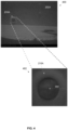
- FIG. 4 is an exemplary image capture of an object submerged in water used for evaluating the water turbidity, according to some embodiments of the present invention.
- An image capture 400 may be captured underwater in water pool such as the water pool 202, for example, a swimming pool 202A.
- a turbidity evaluation engine such as the turbidity evaluation engine 230 executed by a system such as the water turbidly evaluation system 200 may apply one or more image processing algorithms, as describe herein before, to process the image 400 in order to identify one or more submerged objects such as the submerged object 210, for example, a submerged lamp 210A installed in a circumferential wall of the swimming pool 202A.
- the turbidity evaluation engine 230 may extract a section of the image capture 400, for example, an image section 410 depicting the submerged lamp 210A such that the turbidity evaluation engine 230 may process only the image portion containing the submerged lamp 210A rather than the entire image 400 thus reducing computing resources, for example, processing resources, storage resources, time and/or the like.
- the turbidity evaluation engine 230 may compute, estimate, derive and/or otherwise determine the distance to the submerged object 210 in each of the images, i.e., the distance between the submerged object 210 and the imaging sensor 206 which captured the respective image.
- the turbidity evaluation engine 230 may apply one or more methods to determine the distance to the submerged object 210. For example, in case one or more of the received images is associated with the distance information, the turbidity evaluation engine 230 may analyze the received distance information to extract the distance between the imaging sensor 206 which captured the respective image and the submerged object 210.
- the turbidity evaluation engine 230 may calculate and/or derive the distance to the submerged object 210 in one of more of the images based on actual (real-world) values one or more known dimensions of the submerged object 210, for example, a width, a length, a height, a diameter, a length of one or more features of the submerged object 210 (e.g., base, frame, etc.), and/or the like which may be expressed in one or more distance units, for example, meters, centimeters, inches, and/or the like.
- actual dimensions of the submerged object 210 for example, a width, a length, a height, a diameter, a length of one or more features of the submerged object 210 (e.g., base, frame, etc.), and/or the like which may be expressed in one or more distance units, for example, meters, centimeters, inches, and/or the like.
- the turbidity evaluation engine 230 may calculate a value of the known dimension extracted from the respective image. For example, as known in the art, based on a known resolution of the respective image, the turbidity evaluation engine 230 may calculate a value of the known dimension extracted from the respective image in distance unit(s) based on the number of pixels measured for the known dimension in the respective image.
- the turbidity evaluation engine 230 may then calculate the distance to the submerged object 210 in the respective image based on a ratio between the known dimension measured in the respective image and the actual value of the known dimension.
- the turbidity evaluation engine 230 may calculate a luma value for each of a plurality of pixels along one or more gradient lines across (crossing) the submerged object 210 in each of the images captured from the plurality of distances from the submerged object 210.
- Each gradient line across the submerged object 210 may comprise a plurality of pixels having a gradually increasing or a gradually decreasing luma (brightness, intensity) values.
- each pixel along the gradient line may have a higher luma value (brighter) compared to its preceding pixels.
- each pixel along the gradient line may have a lower luma value (darker) compared to its preceding pixels.
- the gradient lines may cross the submerged object 210 and/or part thereof in plurality of directions and/or patterns, for example, a horizontal line, a vertical line, a diagonal line, a curved line, and/or the like.
- the turbidity evaluation engine 230 may select one or more lines across the lamp 210A, in particular gradient lines comprising a plurality of pixels having gradually increasing or gradually decreasing luma values.
- the turbidity evaluation engine 230 may select an exemplary gradient line 302 comprising a plurality of pixels having gradually decreasing luma values, i.e., the first pixels in the gradient line 302 are relatively bright (high luma) and the succeeding pixels along the gradient line 302 are gradually darker (lower luma).
- the turbidity evaluation engine 230 is described herein after to evaluate the water turbidity in the water pool 202 based on analysis of a single gradient line across the submerged object 210. This however, should not be construed as limiting, since the turbidity evaluation engine 230 may select a plurality of gradient lines across the submerged object 210 to evaluate and/or improve evaluation of the water turbidity in the water pool 202.
- the turbidity evaluation engine 230 may calculate a respective maximal intensity change (difference) between a lowest luma value and highest luma value of the pixels along the at selected gradient line across the submerged object 210.
- the maximal intensity change calculated for each gradient line in each image may be expressed by a difference between the lowest luma value identified for any of the pixels along the respective gradient line and the highest luma value identified for any of the pixels along the respective gradient line.
- the turbidity evaluation engine 230 may therefore produce a plurality of maximal intensity changes, each corresponding to a respective one of the distances from the at least partially submerged object 210 from which the respective image was captured.
- the turbidity evaluation engine 230 may map each maximal intensity change to a respective one of the plurality of distances from the submerged object 210 which, as described herein before, is the distance between the submerged object 210 and the imaging sensor 206 at the time of capturing the respective image for which the respective maximal intensity change is computed.
- the turbidity evaluation engine 230 may evaluate the turbidity of the water based on one or more fitting functions adapted to approximate a distribution of the plurality of maximal intensity changes mapped with respect to the plurality of respective distances from the submerged object 210.
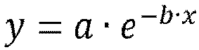
- One exemplary such fitting function is formulated in equation 1 below.
- y is the respective maximal intensity change calculated for each of the plurality of images and thus corresponds to one of the plurality of distances x
- a is a largest maximal intensity change identified among all of the plurality of maximal intensity changes calculated for all gradient lines in all of the images
- b is the estimated turbidity in terms of NTU.
- the turbidity evaluation engine 230 may therefore calculate the turbidity of the water in the water pool 202 according to an optimal fit (approximation) of the fitting function to the distribution of the plurality of maximal intensity changes mapped to the plurality of respective distances. For example, for the fitting function of equation 1, since y, x, and a may be known and/or computed, the turbidity evaluation engine 230 may adapt, adjust and/or manipulate the estimated turbidity b to find a turbidity value b which yields an optimal fit (approximation) of the fitting function to the distribution of the maximal intensity changes mapped to their respective distances.
- FIG. 5 is a graph chart illustrating an exemplary fitting function applied for evaluating water turbidity which maps distribution of brightness changes between pixels of images along a gradient crossing an object to distances from which the images are captured, according to some embodiments of the present invention.
- an exemplary distribution of plurality of maximal intensity changes may be mapped to a plurality of respective distances (measured in meters).
- Each dot in the graph chart represents a maximal intensity change calculated for a gradient line across a submerged object such as the submerged object 210 in an image captured from a certain distance from submerged object 210.
- a turbidity evaluation engine such as the turbidity evaluation engine 230 may attempt to adapt, optimize and/or otherwise manipulate one or roe one or more fitting functions to optimally fit, i.e., follow and/or represent the distribution. For example, assuming the turbidity evaluation engine 230 applies the fitting function of equation 1, illustrated by the graph line 502, the turbidity evaluation engine 230 may search for a turbidity NTU value, b, for which the fitting function best fits the distribution.
- the water turbidity b, evaluated by the turbidity evaluation engine 230 is 0.46 which may be indicative of low turbidity meaning that the water in water pool 202 are significantly clean.
- the turbidity evaluation engine 230 may evaluate the turbidity of the water using one or more trained ML models trained to map images of the submerged object 210 to respective water turbidity values, for example, NTU.
- the ML model(s) may be trained to estimate and/or predict the water turbidity based on analysis of the images and according to the distance to the submerged object 210 in each of the images.
- the ML model(s) may be trained in one or more supervised training sessions using a plurality of labeled training images of the submerged object 210.
- Each of the training images may associate the respective training image with a distance from the submerged object 210 and a measured turbidity value indicating the actual turbidity level of the water in the water pool 202 at the time of capturing the respective training image.
- the measured turbidity value may be measured, computed and/or otherwise determined using one or more methods known in the art, for example, a chemical analysis, measurement of water composition, and/or the like.
- the ML model(s) may be trained with images of the submerged object 210 which is used by the turbidity evaluation engine 230 to evaluate the water turbidity in the water pool 202. Therefore, in case there are a plurality of such submerged objects 210 which may be used by the turbidity evaluation engine 230 to evaluate the water turbidity, the ML model(s) may be trained with labeled training images depicting the plurality of submerged objects 210.
- the labeled training images used to train the ML model(s) may comprise images of the submerged object 210 captured in a plurality of different conditions, view angels and/or the like.
- the training images of the submerged object 210 may comprise images depicting the submerged object 210 from a plurality of different angles.
- the training images of the submerged object 210 may comprise images captured in a plurality of different illumination conditions, for example, typical light, excessive light (bright), low light (dark), natural light, artificial light and/or the like.
- the ML model(s) may be further trained online, post deployment, using images of the submerged object 210 captured in the water pool 202 and labeled with respective turbidity values.
- the online training may significantly improve adaptation and learning of the ML model(s) to the specific water pool 202 which the water turbidity evaluation system 200 is deployed to monitor and evaluate its water turbidity.
- the turbidity evaluation engine 230 may therefore evaluate the turbidity of the water in the water pool 202, for example, in terms of NTU.
- the turbidity evaluation engine 230 may initiate one or more actions according to the evaluated (estimated) turbidity of the water in the water pool 202.
- the turbidity evaluation engine 230 may initiate one or more actions in case the water turbidity exceeds a certain threshold and actin may be required to treat the water in the water pool 202 in order to reduce the water turbidity and improve clarity, purity and/or quality of the water.
- the threshold used by the turbidity evaluation engine 230 to determine whether turbidity of the water in the water pool 202 is acceptable or not may be a predefined threshold.
- the threshold may be predefined according to one or more attributes and/or parameters of the water pool 202.
- the threshold may be predefined to a relatively low value such that the turbidity of the water in the swimming pool is maintained at low level to ensure high visibility in the swimming pool and/or prevent health risks.
- the threshold may be predefined to a higher low value since the turbidity of the water in the fountain may be slightly more turbid as no people enter it.
- the threshold may be dynamic adjusted and/or learned over time. For example, assuming that, based on a certain threshold value, the turbidity evaluation engine 230 determines the water in the water pool 202 are highly turbid while a visual inspection of the water pool 202 reveals that the water is actually significantly clear. In such case, the threshold may be adjusted, specifically increased thus reducing sensitivity of the turbidity evaluation engine 230 which may determine that the water in the water pool 202 is actually turbid at higher levels of turbidity.
- the threshold may be adjusted, specifically reduced in order for the turbidity evaluation engine 230 to detect such turbidity conditions as soon as possible so that measures may be taken to clean the water.
- the actions initiated by the turbidity evaluation engine 230 may include informative actions and/or proactive cleaning procedures employed to treat the water in the water pool 202.
- the turbidity evaluation engine 230 may transmit one or more alert messages.
- the alert messages may be transmitted for example, to one or more maintenance and/or control personnel, service and/or the like who may evaluate the turbidity of the water in the water pool 202, optionally combined with one or more other conditions of the water pool 202 and take action accordingly if needed.
- the turbidity evaluation engine 230 may induce operation of one or more water cleaning equipment, for example, a cleaning system, a pool cleaning robot, a purification systems and/or the like.
- the turbidity evaluation engine 230 may communicate with water cleaning equipment, for example, a pool cleaning robot deployed to clean the swimming pool. In such case, the turbidity evaluation engine 230 may transmit an activation command to the pool cleaning robot which, in response, may start cleaning the swimming pool.
- the turbidity evaluation engine 230 may transmit the evaluated water turbidity to one or more purification systems of the swimming pool which may release and/or dispose one or more materials, substances, minerals and/or the like, for example, chlorine and/or the like to clean the water in the swimming pool.
- the water turbidity evaluation system 200 is integrated with water cleaning equipment, for example, a purification system of the water pool such that the turbidity evaluation engine 230 is executed by the purification system.
- the turbidity evaluation engine 230 may operate the purification system directly to initiate one or more actions to clean the water in the water pool 202, for example, circulate the water through one or more filtering systems and/or devices, release chlorine to the water, replace the water or part thereof, and/or the like.
- the turbidity may apply an intensity STD analysis to evaluate the turbidity of the water in a water pool such as the water pool 202, in particular, based on STD of intensity of pixels depicting one or more varying color patterns marked and/or formed on one or more surfaces of the water pool 202, for example, a circumferential wall, the floor, and/or part thereof.
- FIG. 6 is a flowchart of a second exemplary process of evaluating water turbidity based on analysis of images depicting varying color under water patterns, according to some embodiments of the present disclosure.
- An exemplary process may be executed by a turbidity evaluation engine such as the turbidity evaluation engine 230 executed by a turbidity evaluation system such as the turbidity evaluation system 200 to evaluate the turbidity of the water in a water pool such as the water pool 202 based on STD of the intensity of pixels in one or more images captured underwater in water pool such as the water pool 202.
- a turbidity evaluation engine such as the turbidity evaluation engine 230 executed by a turbidity evaluation system such as the turbidity evaluation system 200 to evaluate the turbidity of the water in a water pool such as the water pool 202 based on STD of the intensity of pixels in one or more images captured underwater in water pool such as the water pool 202.
- the process 600 starts with the turbidity evaluation engine 230 receiving one or more images, for example, an image, a frame of a video stream and/or the like captured underwater by one or more imaging sensors such as the imaging sensors 206 deployed in the water pool 202.
- images for example, an image, a frame of a video stream and/or the like captured underwater by one or more imaging sensors such as the imaging sensors 206 deployed in the water pool 202.
- the image(s) may depict one or more varying color patterns marked, embedded and/or formed on one or more surfaces of the water pool 202, for example, a circumferential wall, the floor, and/or part thereof.
- evaluating the turbidity of the water in the water pool 202 according to the process 600 is based on analysis of a single image of a single varying color pattern. This however, should not be construed as limiting since the process 600 may be extended and/or repeated to evaluate and/or enhance evaluation of the water turbidity in the water pool 202 based on analysis of a plurality of images of the varying color pattern and/or based on analysis of a plurality of images of a plurality of varying color patterns marked, embedded and/or formed on one or more of the surfaces of the water pool 202.
- the varying color pattern on the surface which may portray practically any pattern other than solid filling of the surface may be marked in a combination of a plurality of colors shades which are distinguishable from each other, for example, black and white, blue and white, yellow and green and/or the like.
- the varying color pattern may be placed, formed and/or set on the surface of the water pool 202 in one or more manners and/or methods.
- the varying color pattern may be marked on the surface, for example, painted, engraved and/or the like on the surface(s) of the water pool 202.
- the varying color pattern may be part of a texture of the surface formed by the built and/or coating of the surface, for example, a pattern formed by bricks of different color, a mosaic, and/or the like.
- the turbidity evaluation engine 230 may divide the received image to a plurality of segments of equal size.
- the size of the segments should be relatively small such that multiple segments may depict different parts of the varying color pattern.
- the number of segments and/or the size of the segments may be therefore predefined, defined and/or set according to one or more parameters of the received image and/or the varying color pattern portrayed in the image. For example, assuming the image size is 640 x 480 pixels, the turbidity evaluation engine 230 may divide the image to segments of 32 x 24 pixels each. In another example, assuming the varying color pattern is portrayed in only half of the image with a size of 640 x 480 pixels, the turbidity evaluation engine 230 may use only the relevant half of the image and divide it to segments of 16 x 12 pixels.
- the turbidity evaluation engine 230 may calculate a luma value for each of the pixels of each of the segments of the image.
- the turbidity evaluation engine 230 may calculate the luma value of each pixel as described herein before in step 108 of the process 100.
- the turbidity evaluation engine 230 may calculate an STD, as known in the art, for each of the segments based on the luma values of the plurality of pixels of the respective segment.
- the turbidity evaluation engine 230 may generate a histogram for inverse values of the intensity STD ( 1 STD ) of the plurality of segments.
- the turbidity evaluation engine 230 may divide each of the images to segments and generate a plurality of histograms each for the 1 STD of the plurality of segments of each of the images. In such case, the turbidity evaluation engine 230 may aggregate the plurality of histograms, for example, sum the histograms to create an aggregated histogram for the 1 STD of the segments of all received images.
- the turbidity evaluation engine 230 may evaluate turbidity of the water in the water pool 202 based on the histogram of the 1 STD of the plurality of segments of the image or optionally based on the aggregated histogram if created for the plurality of images of the varying color pattern.
- the turbidity evaluation engine 230 may apply one or more methods, techniques and/or algorithms to calculate, derive and/or estimate the water turbidity based on the 1 STD histogram.
- the turbidity evaluation engine 230 may estimate the water turbidity based on a peak of the 1 STD histogram and/or of the 1 STD aggregated histogram if created. In such case, the turbidity evaluation engine 230 may estimate the water turbidity based on one or more predefined and/or dynamically adjusted values and/or thresholds defined for histogram peak. For example, in case the value of the peak of the histogram is higher than a certain value, for example, 20, the turbidity evaluation engine 230 may determine that water turbidity is significantly high.
- the turbidity evaluation engine 230 may estimate the water turbidity based on a Weibull distribution generated based on the 1 STD histogram and/or the 1 STD aggregated histogram if created. In such case, the turbidity evaluation engine 230 may estimate the water turbidity based on one or more predefined and/or dynamically adjusted values and/or thresholds defined for one or more parameters of the Weibull distribution, for example, a shape parameter (k), and/or a scale parameter ( ⁇ ). For example, in case the value of the shape parameter is higher than a certain value, for example, 1.05 ( k > 1.05), the turbidity evaluation engine 230 may determine that water turbidity is significantly low.
- the turbidity evaluation engine 230 may initiate one or more actions according to the evaluated (estimated) turbidity of the water in the water pool 202 as described in step 114 of the process 100.
- composition or method may include additional ingredients and/or steps, but only if the additional ingredients and/or steps do not materially alter the basic and novel characteristics of the claimed composition or method.
- a compound or “at least one compound” may include a plurality of compounds, including mixtures thereof.
- range format is merely for convenience and brevity and should not be construed as an inflexible limitation on the scope of the invention. Accordingly, the description of a range should be considered to have specifically disclosed all the possible subranges as well as individual numerical values within that range. For example, description of a range such as from 1 to 6 should be considered to have specifically disclosed subranges such as from 1 to 3, from 1 to 4, from 1 to 5, from 2 to 4, from 2 to 6, from 3 to 6 etc., as well as individual numbers within that range, for example, 1, 2, 3, 4, 5, and 6. This applies regardless of the breadth of the range.
Landscapes
- Health & Medical Sciences (AREA)
- Life Sciences & Earth Sciences (AREA)
- Chemical & Material Sciences (AREA)
- Physics & Mathematics (AREA)
- Immunology (AREA)
- Biochemistry (AREA)
- General Health & Medical Sciences (AREA)
- General Physics & Mathematics (AREA)
- Analytical Chemistry (AREA)
- Pathology (AREA)
- Engineering & Computer Science (AREA)
- Spectroscopy & Molecular Physics (AREA)
- Food Science & Technology (AREA)
- Medicinal Chemistry (AREA)
- Biomedical Technology (AREA)
- Molecular Biology (AREA)
- Dispersion Chemistry (AREA)
- Investigating Or Analysing Materials By Optical Means (AREA)
Claims (15)
- Verfahren zum Schätzen von Wassertrübung unter Verwendung von Bilddaten, umfassend:
Aufnehmen, unter Wasser durch mindestens einen Bildsensor (206), einer Vielzahl von Bildern; Verwenden mindestens eines Prozessors (222) zu Folgendem:Analysieren der Vielzahl von Bildern, die von dem mindestens einen Bildsensor (206) aufgenommen werden,um mindestens ein Objekt (210) zu identifizieren (104), das zumindest teilweise in dem Wasser untergetaucht ist und sich von seinem Hintergrund unterscheiden lässt, wobei jedes der Vielzahl von Bildern aus einem jeweiligen einer Vielzahl von Abständen zwischen dem mindestens einen Bildsensor (206) und dem mindestens einen Objekt (210) aufgenommen wird;Berechnen (108) eines Luma-Werts für jedes einer Vielzahl von Pixeln entlang einer entsprechenden mindestens einen Intensitätsgradientenlinie über das mindestens eine Objekt (210) in jedem aus der Vielzahl von Bildern:Berechnen (110), für jedes Bild, einer jeweiligen maximalen Intensitätsänderung zwischen einem niedrigsten Luma-Wert und einem höchsten Luma-Wert der Pixel entlang der mindestens einen Intensitätsgradientenlinie in dem jeweiligen Bild;Bewerten (112) einer Trübung des Wassers basierend auf einer Zuordnung der jeweiligen maximalen Intensitätsänderung zu jeder der Vielzahl von Abständen; undEinleiten (114) mindestens einer Aktion, wenn die Trübung einen gewissen Schwellenwert überschreitet. - Verfahren nach Anspruch 1, wobei eine Trübung des Wassers basierend auf mindestens einer Anpassungsfunktion bewertet wird, die angepasst ist, um eine Verteilung der maximalen Intensitätsänderungen, die in Bezug auf die Abstände von dem mindestens einen Objekt (210) zugeordnet werden, anzunähern.
- Verfahren nach einem der vorherigen Ansprüche, wobei die mindestens eine Anpassungsfunktion wie folgt formuliert ist:
- Verfahren nach einem der vorherigen Ansprüche, wobei eine Trübung des Wassers unter Verwendung mindestens eines Modells maschinellen Lernens (ML) bewertet wird, das trainiert ist, um Bilder des mindestens einen Objekts (210) aus der Vielzahl von Abständen jeweiligen Trübungswerten zuzuordnen.
- Verfahren nach einem der vorherigen Ansprüche, wobei das mindestens eine trainierte ML-Modell unter Verwendung einer Vielzahl von beschrifteten Trainingsbildern trainiert wird, die das mindestens eine Objekt (210) aus einer Vielzahl von Abständen darstellen, wobei eine Beschriftung von jedem der Vielzahl von beschrifteten Trainingsbildern einen Abstand, aus dem das jeweilige Trainingsbild aufgenommen wird, und einen gemessenen Trübungswert angibt.
- Verfahren nach einem der vorherigen Ansprüche, wobei das Wasser Wasser eines ein Schwimmbads (202) ist.
- Verfahren nach einem der vorherigen Ansprüche, wobei die mindestens eine Aktion ein Mitglied einer Gruppe ist, die aus Folgendem besteht: Senden mindestens einer Warnmeldung und Einleiten eines Betriebs einer Wasserreinigungsanlage, wenn die Trübung einen vordefinierten Schwellenwert überschreitet.
- Verfahren nach einem der vorherigen Ansprüche, wobei das mindestens eine Objekt (210) unter Verwendung mindestens eines visuellen Analysealgorithmus erfasst wird, der zum Analysieren der Vielzahl von Bildern angewendet wird.
- Verfahren nach Anspruch 1, ferner umfassend ein Umwandeln mindestens eines der Vielzahl von Bildern in eine Vielzahl von entsprechenden Graustufenbildern, bevor der Luma-Wert für jedes der Vielzahl von Pixeln berechnet wird.
- Verfahren nach einem der vorherigen Ansprüche, ferner umfassend ein Vorverarbeiten mindestens eines der Vielzahl von Bildern unter Verwendung mindestens eines Filters, der konfiguriert ist, um mindestens eines der Vielzahl von Bildern zu verbessern.
- Verfahren nach einem der vorherigen Ansprüche, wobei der Abstand zu dem mindestens einen Objekt (210) unter Verwendung mindestens einer Abstandsmessvorrichtung berechnet wird.
- Verfahren nach einem der vorherigen Ansprüche, wobei der Abstand zu dem mindestens einen Objekt basierend auf mindestens einer bekannten Dimension des mindestens einen Objekts (210) berechnet wird, die aus einem jeweiligen Bild extrahiert wird.
- Verfahren nach einem der vorherigen Ansprüche, wobei die mindestens eine Gradientenlinie ein Mitglied einer Gruppe ist, die aus Folgendem besteht: einer horizontalen Linie, einer vertikalen Linie, einer diagonalen Linie und einer gekrümmten Linie.
- Verfahren nach einem der vorherigen Ansprüche, wobei die Gradientenlinie, die zum Berechnen der Intensitätsänderung ausgewählt wird, eine Vielzahl von Pixeln mit allmählich zunehmendem oder allmählich abnehmendem Luma-Wert umfasst.
- System (200) zum Bewerten von Wassertrübung unter Verwendung von Bilddaten, umfassend:mindestens einen Bildsensor (206), der unter Wasser eine Vielzahl von Bildern aufnimmt;mindestens einen Prozessor (222), der konfiguriert ist, um einen Code auszuführen, der Code umfassend:Codeanweisungen zum Analysieren der Vielzahl von Bildern, die unter Wasser von dem mindestens einen Bildsensor (206) aufgenommen werden, um mindestens ein Objekt (210) zu identifizieren (104), das zumindest teilweise in dem Wasser eingetaucht ist und sich von seinem Hintergrund unterscheiden lässt, wobei jedes der Vielzahl von Bildern aus einem jeweiligen einer Vielzahl von Abständen zwischen dem mindestens einen Bildsensor (206) und dem mindestens einen Objekt (210) aufgenommen wird;Codeanweisungen zum Berechnen (108) eines Luma-Werts für jedes aus einer Vielzahl von Pixeln entlang einer entsprechenden mindestens einen Intensitätsgradientenlinie über das mindestens eine Objekt (210) in jedem aus der Vielzahl von Bildern;Codeanweisungen zum Berechnen (110), für jedes Bild, einer jeweiligen maximalen Intensitätsänderung zwischen einem niedrigsten Luma-Wert und einem höchsten Luma-Wert der Pixel entlang der mindestens einen Intensitätsgradientenlinie in dem jeweiligen Bild;Codeanweisungen zum Bewerten (112) einer Trübung des Wassers basierend auf einem Zuordnen der jeweiligen maximalen Intensitätsänderung zu jedem der Vielzahl von Abständen; undCodeanweisungen zum Einleiten (114) mindestens einer Aktion, wenn die Trübung einen bestimmten Schwellenwert überschreitet.
Applications Claiming Priority (1)
| Application Number | Priority Date | Filing Date | Title |
|---|---|---|---|
| IL294718A IL294718B2 (en) | 2022-07-12 | 2022-07-12 | Water turbidity evaluation using image sensor |
Publications (2)
| Publication Number | Publication Date |
|---|---|
| EP4306937A1 EP4306937A1 (de) | 2024-01-17 |
| EP4306937B1 true EP4306937B1 (de) | 2025-06-11 |
Family
ID=87280290
Family Applications (1)
| Application Number | Title | Priority Date | Filing Date |
|---|---|---|---|
| EP23185061.1A Active EP4306937B1 (de) | 2022-07-12 | 2023-07-12 | Wassertrübungsbewertung mit bildsensor |
Country Status (5)
| Country | Link |
|---|---|
| US (1) | US20240019359A1 (de) |
| EP (1) | EP4306937B1 (de) |
| CN (1) | CN117405633A (de) |
| AU (1) | AU2023204610A1 (de) |
| IL (1) | IL294718B2 (de) |
Families Citing this family (4)
| Publication number | Priority date | Publication date | Assignee | Title |
|---|---|---|---|---|
| CN118307109B (zh) * | 2024-06-11 | 2024-10-01 | 陕西省水务集团水处理设备有限公司 | 基于机器视觉的水处理过程中的加药控制方法 |
| CN119310248B (zh) * | 2024-10-11 | 2025-10-10 | 深圳市光鉴科技有限公司 | 一种适用于机器人的水质判断方法、系统、设备及存储介质 |
| CN119534788B (zh) * | 2025-01-23 | 2025-05-09 | 广州元沣智能科技有限公司 | 一种基于多源数据感知的水质监测系统 |
| CN120823210B (zh) * | 2025-09-17 | 2025-12-05 | 南京大学 | 一种面向岛礁浅水区域的遥感影像质量评价方法 |
Family Cites Families (15)
| Publication number | Priority date | Publication date | Assignee | Title |
|---|---|---|---|---|
| JP3107700B2 (ja) * | 1994-04-15 | 2000-11-13 | 日立造船株式会社 | 水の濁度測定方法および濁度測定装置 |
| US11313678B2 (en) * | 2011-06-30 | 2022-04-26 | The Regents Of The University Of Colorado | Remote measurement of shallow depths in semi-transparent media |
| CN102565062B (zh) * | 2012-03-02 | 2015-04-29 | 汕头市领域安防系统设备有限公司 | 基于图像灰度检测的液体浑浊度测试方法 |
| EP4009032A1 (de) * | 2014-04-21 | 2022-06-08 | Aber Instruments, Inc. | Partikelsensor mit störstoffdiskriminierung |
| WO2016046719A1 (en) * | 2014-09-23 | 2016-03-31 | Maytronics Ltd. | Multi parameter swimming pool fluid analysis and regulating method and device |
| WO2017175261A1 (ja) * | 2016-04-04 | 2017-10-12 | パナソニックIpマネジメント株式会社 | 濁度検出装置、濁度検出方法及び液中検査装置 |
| DK3355048T3 (da) * | 2016-05-19 | 2021-07-12 | Fuji Electric Co Ltd | Vandkvalitetsanalysator |
| WO2018122857A1 (en) * | 2016-12-29 | 2018-07-05 | Maytronics Ltd. | A system and a method for comprehensive monitoring, analysis and maintenance of water and equipment in swimming pools |
| US11498858B2 (en) * | 2017-05-02 | 2022-11-15 | ClearCorp | Methods for optimizing water treatment coagulant dosing |
| ES2847523T3 (es) * | 2018-02-04 | 2021-08-03 | Maytronics Ltd | Robot de limpieza de piscinas y método para representar la imagen de una piscina |
| US11650190B2 (en) * | 2018-03-27 | 2023-05-16 | Flying Gybe Inc. | Hyperspectral sensing system and methods |
| CN110274893A (zh) * | 2019-07-25 | 2019-09-24 | 淮北师范大学 | 基于红外摄像的水体浊度测量装置、图像采集系统和方法 |
| US10725438B1 (en) * | 2019-10-01 | 2020-07-28 | 11114140 Canada Inc. | System and method for automated water operations for aquatic facilities using image-based machine learning |
| CN110672524A (zh) * | 2019-10-22 | 2020-01-10 | 浙江卓锦环保科技股份有限公司 | 一种适用于智慧水环境的水体浊度检测方法 |
| CN113155784A (zh) * | 2021-03-19 | 2021-07-23 | 东营市阔海水产科技有限公司 | 水体透明度检测方法、终端设备及存储介质 |
-
2022
- 2022-07-12 IL IL294718A patent/IL294718B2/en unknown
-
2023
- 2023-07-12 CN CN202310856170.9A patent/CN117405633A/zh active Pending
- 2023-07-12 EP EP23185061.1A patent/EP4306937B1/de active Active
- 2023-07-12 US US18/220,918 patent/US20240019359A1/en active Pending
- 2023-07-12 AU AU2023204610A patent/AU2023204610A1/en active Pending
Also Published As
| Publication number | Publication date |
|---|---|
| EP4306937A1 (de) | 2024-01-17 |
| US20240019359A1 (en) | 2024-01-18 |
| IL294718B2 (en) | 2024-05-01 |
| AU2023204610A1 (en) | 2024-02-01 |
| IL294718A (en) | 2024-01-01 |
| IL294718B1 (en) | 2024-01-01 |
| CN117405633A (zh) | 2024-01-16 |
Similar Documents
| Publication | Publication Date | Title |
|---|---|---|
| EP4306937A1 (de) | Wassertrübungsbewertung mit bildsensor | |
| CN113252700B (zh) | 一种结构裂缝检测方法、设备及系统 | |
| Satat et al. | Towards photography through realistic fog | |
| Zhang et al. | Hazerd: an outdoor scene dataset and benchmark for single image dehazing | |
| CN101567044B (zh) | 一种人脸图像质量检测方法 | |
| CN103994724B (zh) | 基于数字图像处理技术的结构二维位移及应变监测方法 | |
| Hernández et al. | Water elevation measurements using binary image analysis for 2D hydrodynamic experiments | |
| CN112330593A (zh) | 基于深度学习网络的建筑物表面裂缝检测方法 | |
| KR101674391B1 (ko) | 렌즈 오염도 측정 장치 및 방법 | |
| CN111160293A (zh) | 基于特征金字塔网络的小目标船只检测方法及系统 | |
| CN104851086A (zh) | 一种针对缆索表面缺陷的图像检测方法 | |
| KR100939424B1 (ko) | 유리 기판의 결함 검사 방법 | |
| CN112348804A (zh) | 由基坑位移导致的裂缝监测方法、系统、装置和存储介质 | |
| CN103632369A (zh) | 块平均清晰度组合无参考水下图像通用性质量检测方法 | |
| CN116542963B (zh) | 一种基于机器学习的浮法玻璃缺陷检测系统及检测方法 | |
| CN109927675A (zh) | 一种雨刷控制方法、装置、设备及存储介质 | |
| CN112345542A (zh) | 一种隧道掌子面裂隙快速识别的方法 | |
| CN117372939A (zh) | 井下恶劣条件下机器视觉识别钢带孔方法和装置 | |
| CN106408526A (zh) | 一种基于多层矢量图的能见度检测方法 | |
| CN117078961A (zh) | 应用于车辆的阳光照射角度判定方法、装置、设备及介质 | |
| CN115272785B (zh) | 一种基于雾感知密度估计的海雾浓度检测预警方法 | |
| JP3500425B2 (ja) | 可視画像式路面状況把握装置における路面状況判定方法 | |
| CN109211138A (zh) | 一种外形检测系统和方法 | |
| CN105719252A (zh) | 一种铁路巡检图像实时高动态范围绘制方法和装置 | |
| JP3612565B2 (ja) | 路面状況判定方法 |
Legal Events
| Date | Code | Title | Description |
|---|---|---|---|
| PUAI | Public reference made under article 153(3) epc to a published international application that has entered the european phase |
Free format text: ORIGINAL CODE: 0009012 |
|
| STAA | Information on the status of an ep patent application or granted ep patent |
Free format text: STATUS: REQUEST FOR EXAMINATION WAS MADE |
|
| 17P | Request for examination filed |
Effective date: 20230712 |
|
| AK | Designated contracting states |
Kind code of ref document: A1 Designated state(s): AL AT BE BG CH CY CZ DE DK EE ES FI FR GB GR HR HU IE IS IT LI LT LU LV MC ME MK MT NL NO PL PT RO RS SE SI SK SM TR |
|
| GRAP | Despatch of communication of intention to grant a patent |
Free format text: ORIGINAL CODE: EPIDOSNIGR1 |
|
| STAA | Information on the status of an ep patent application or granted ep patent |
Free format text: STATUS: GRANT OF PATENT IS INTENDED |
|
| RIC1 | Information provided on ipc code assigned before grant |
Ipc: G01N 21/01 20060101ALI20241212BHEP Ipc: G01N 21/94 20060101ALI20241212BHEP Ipc: G01N 33/18 20060101ALI20241212BHEP Ipc: G01N 21/53 20060101AFI20241212BHEP |
|
| INTG | Intention to grant announced |
Effective date: 20250107 |
|
| GRAS | Grant fee paid |
Free format text: ORIGINAL CODE: EPIDOSNIGR3 |
|
| GRAA | (expected) grant |
Free format text: ORIGINAL CODE: 0009210 |
|
| STAA | Information on the status of an ep patent application or granted ep patent |
Free format text: STATUS: THE PATENT HAS BEEN GRANTED |
|
| AK | Designated contracting states |
Kind code of ref document: B1 Designated state(s): AL AT BE BG CH CY CZ DE DK EE ES FI FR GB GR HR HU IE IS IT LI LT LU LV MC ME MK MT NL NO PL PT RO RS SE SI SK SM TR |
|
| REG | Reference to a national code |
Ref country code: GB Ref legal event code: FG4D |
|
| REG | Reference to a national code |
Ref country code: CH Ref legal event code: EP |
|
| REG | Reference to a national code |
Ref country code: IE Ref legal event code: FG4D |
|
| REG | Reference to a national code |
Ref country code: DE Ref legal event code: R096 Ref document number: 602023003915 Country of ref document: DE |
|
| PG25 | Lapsed in a contracting state [announced via postgrant information from national office to epo] |
Ref country code: ES Free format text: LAPSE BECAUSE OF FAILURE TO SUBMIT A TRANSLATION OF THE DESCRIPTION OR TO PAY THE FEE WITHIN THE PRESCRIBED TIME-LIMIT Effective date: 20250611 Ref country code: FI Free format text: LAPSE BECAUSE OF FAILURE TO SUBMIT A TRANSLATION OF THE DESCRIPTION OR TO PAY THE FEE WITHIN THE PRESCRIBED TIME-LIMIT Effective date: 20250611 |
|
| REG | Reference to a national code |
Ref country code: LT Ref legal event code: MG9D |
|
| PG25 | Lapsed in a contracting state [announced via postgrant information from national office to epo] |
Ref country code: GR Free format text: LAPSE BECAUSE OF FAILURE TO SUBMIT A TRANSLATION OF THE DESCRIPTION OR TO PAY THE FEE WITHIN THE PRESCRIBED TIME-LIMIT Effective date: 20250912 Ref country code: NO Free format text: LAPSE BECAUSE OF FAILURE TO SUBMIT A TRANSLATION OF THE DESCRIPTION OR TO PAY THE FEE WITHIN THE PRESCRIBED TIME-LIMIT Effective date: 20250911 |
|
| REG | Reference to a national code |
Ref country code: NL Ref legal event code: MP Effective date: 20250611 |
|
| PG25 | Lapsed in a contracting state [announced via postgrant information from national office to epo] |
Ref country code: BG Free format text: LAPSE BECAUSE OF FAILURE TO SUBMIT A TRANSLATION OF THE DESCRIPTION OR TO PAY THE FEE WITHIN THE PRESCRIBED TIME-LIMIT Effective date: 20250611 |
|
| PG25 | Lapsed in a contracting state [announced via postgrant information from national office to epo] |
Ref country code: HR Free format text: LAPSE BECAUSE OF FAILURE TO SUBMIT A TRANSLATION OF THE DESCRIPTION OR TO PAY THE FEE WITHIN THE PRESCRIBED TIME-LIMIT Effective date: 20250611 |
|
| PGFP | Annual fee paid to national office [announced via postgrant information from national office to epo] |
Ref country code: AT Payment date: 20251020 Year of fee payment: 3 |
|
| PG25 | Lapsed in a contracting state [announced via postgrant information from national office to epo] |
Ref country code: RS Free format text: LAPSE BECAUSE OF FAILURE TO SUBMIT A TRANSLATION OF THE DESCRIPTION OR TO PAY THE FEE WITHIN THE PRESCRIBED TIME-LIMIT Effective date: 20250911 |
|
| PG25 | Lapsed in a contracting state [announced via postgrant information from national office to epo] |
Ref country code: LV Free format text: LAPSE BECAUSE OF FAILURE TO SUBMIT A TRANSLATION OF THE DESCRIPTION OR TO PAY THE FEE WITHIN THE PRESCRIBED TIME-LIMIT Effective date: 20250611 |
|
| PG25 | Lapsed in a contracting state [announced via postgrant information from national office to epo] |
Ref country code: NL Free format text: LAPSE BECAUSE OF FAILURE TO SUBMIT A TRANSLATION OF THE DESCRIPTION OR TO PAY THE FEE WITHIN THE PRESCRIBED TIME-LIMIT Effective date: 20250611 |
|
| PG25 | Lapsed in a contracting state [announced via postgrant information from national office to epo] |
Ref country code: PT Free format text: LAPSE BECAUSE OF FAILURE TO SUBMIT A TRANSLATION OF THE DESCRIPTION OR TO PAY THE FEE WITHIN THE PRESCRIBED TIME-LIMIT Effective date: 20251013 |
|
| REG | Reference to a national code |
Ref country code: AT Ref legal event code: MK05 Ref document number: 1802629 Country of ref document: AT Kind code of ref document: T Effective date: 20250611 |
|
| PG25 | Lapsed in a contracting state [announced via postgrant information from national office to epo] |
Ref country code: IS Free format text: LAPSE BECAUSE OF FAILURE TO SUBMIT A TRANSLATION OF THE DESCRIPTION OR TO PAY THE FEE WITHIN THE PRESCRIBED TIME-LIMIT Effective date: 20251011 |
|
| PG25 | Lapsed in a contracting state [announced via postgrant information from national office to epo] |
Ref country code: AT Free format text: LAPSE BECAUSE OF FAILURE TO SUBMIT A TRANSLATION OF THE DESCRIPTION OR TO PAY THE FEE WITHIN THE PRESCRIBED TIME-LIMIT Effective date: 20250611 Ref country code: SM Free format text: LAPSE BECAUSE OF FAILURE TO SUBMIT A TRANSLATION OF THE DESCRIPTION OR TO PAY THE FEE WITHIN THE PRESCRIBED TIME-LIMIT Effective date: 20250611 |
|
| PG25 | Lapsed in a contracting state [announced via postgrant information from national office to epo] |
Ref country code: CZ Free format text: LAPSE BECAUSE OF FAILURE TO SUBMIT A TRANSLATION OF THE DESCRIPTION OR TO PAY THE FEE WITHIN THE PRESCRIBED TIME-LIMIT Effective date: 20250611 |
|
| PG25 | Lapsed in a contracting state [announced via postgrant information from national office to epo] |
Ref country code: PL Free format text: LAPSE BECAUSE OF FAILURE TO SUBMIT A TRANSLATION OF THE DESCRIPTION OR TO PAY THE FEE WITHIN THE PRESCRIBED TIME-LIMIT Effective date: 20250611 |
|
| PG25 | Lapsed in a contracting state [announced via postgrant information from national office to epo] |
Ref country code: EE Free format text: LAPSE BECAUSE OF FAILURE TO SUBMIT A TRANSLATION OF THE DESCRIPTION OR TO PAY THE FEE WITHIN THE PRESCRIBED TIME-LIMIT Effective date: 20250611 |
|
| PG25 | Lapsed in a contracting state [announced via postgrant information from national office to epo] |
Ref country code: SK Free format text: LAPSE BECAUSE OF FAILURE TO SUBMIT A TRANSLATION OF THE DESCRIPTION OR TO PAY THE FEE WITHIN THE PRESCRIBED TIME-LIMIT Effective date: 20250611 |
|
| REG | Reference to a national code |
Ref country code: DE Ref legal event code: R119 Ref document number: 602023003915 Country of ref document: DE |
|
| PG25 | Lapsed in a contracting state [announced via postgrant information from national office to epo] |
Ref country code: RO Free format text: LAPSE BECAUSE OF FAILURE TO SUBMIT A TRANSLATION OF THE DESCRIPTION OR TO PAY THE FEE WITHIN THE PRESCRIBED TIME-LIMIT Effective date: 20250611 |
|
| PG25 | Lapsed in a contracting state [announced via postgrant information from national office to epo] |
Ref country code: LU Free format text: LAPSE BECAUSE OF NON-PAYMENT OF DUE FEES Effective date: 20250712 |
|
| REG | Reference to a national code |
Ref country code: BE Ref legal event code: MM Effective date: 20250731 |
|
| PG25 | Lapsed in a contracting state [announced via postgrant information from national office to epo] |
Ref country code: MC Free format text: LAPSE BECAUSE OF FAILURE TO SUBMIT A TRANSLATION OF THE DESCRIPTION OR TO PAY THE FEE WITHIN THE PRESCRIBED TIME-LIMIT Effective date: 20250611 |
|
| PG25 | Lapsed in a contracting state [announced via postgrant information from national office to epo] |
Ref country code: DK Free format text: LAPSE BECAUSE OF FAILURE TO SUBMIT A TRANSLATION OF THE DESCRIPTION OR TO PAY THE FEE WITHIN THE PRESCRIBED TIME-LIMIT Effective date: 20250611 Ref country code: DE Free format text: LAPSE BECAUSE OF NON-PAYMENT OF DUE FEES Effective date: 20260203 |
|
| PG25 | Lapsed in a contracting state [announced via postgrant information from national office to epo] |
Ref country code: IT Free format text: LAPSE BECAUSE OF FAILURE TO SUBMIT A TRANSLATION OF THE DESCRIPTION OR TO PAY THE FEE WITHIN THE PRESCRIBED TIME-LIMIT Effective date: 20250611 Ref country code: BE Free format text: LAPSE BECAUSE OF NON-PAYMENT OF DUE FEES Effective date: 20250731 |
|
| PLBE | No opposition filed within time limit |
Free format text: ORIGINAL CODE: 0009261 |
|
| STAA | Information on the status of an ep patent application or granted ep patent |
Free format text: STATUS: NO OPPOSITION FILED WITHIN TIME LIMIT |
|
| REG | Reference to a national code |
Ref country code: CH Ref legal event code: L10 Free format text: ST27 STATUS EVENT CODE: U-0-0-L10-L00 (AS PROVIDED BY THE NATIONAL OFFICE) Effective date: 20260423 |