EP4306918A1 - Informationsverarbeitungsvorrichtung, informationsverarbeitungsverfahren und programm - Google Patents
Informationsverarbeitungsvorrichtung, informationsverarbeitungsverfahren und programm Download PDFInfo
- Publication number
- EP4306918A1 EP4306918A1 EP22766590.8A EP22766590A EP4306918A1 EP 4306918 A1 EP4306918 A1 EP 4306918A1 EP 22766590 A EP22766590 A EP 22766590A EP 4306918 A1 EP4306918 A1 EP 4306918A1
- Authority
- EP
- European Patent Office
- Prior art keywords
- vibration
- frequency
- information
- information processing
- event
- Prior art date
- Legal status (The legal status is an assumption and is not a legal conclusion. Google has not performed a legal analysis and makes no representation as to the accuracy of the status listed.)
- Pending
Links
Images


Classifications
-
- H—ELECTRICITY
- H04—ELECTRIC COMMUNICATION TECHNIQUE
- H04N—PICTORIAL COMMUNICATION, e.g. TELEVISION
- H04N25/00—Circuitry of solid-state image sensors [SSIS]; Control thereof
- H04N25/47—Image sensors with pixel address output; Event-driven image sensors; Selection of pixels to be read out based on image data
-
- G—PHYSICS
- G01—MEASURING; TESTING
- G01H—MEASUREMENT OF MECHANICAL VIBRATIONS OR ULTRASONIC, SONIC OR INFRASONIC WAVES
- G01H9/00—Measuring mechanical vibrations or ultrasonic, sonic or infrasonic waves by using radiation-sensitive means, e.g. optical means
-
- G—PHYSICS
- G01—MEASURING; TESTING
- G01M—TESTING STATIC OR DYNAMIC BALANCE OF MACHINES OR STRUCTURES; TESTING OF STRUCTURES OR APPARATUS, NOT OTHERWISE PROVIDED FOR
- G01M7/00—Vibration-testing of structures; Shock-testing of structures
-
- H—ELECTRICITY
- H04—ELECTRIC COMMUNICATION TECHNIQUE
- H04N—PICTORIAL COMMUNICATION, e.g. TELEVISION
- H04N23/00—Cameras or camera modules comprising electronic image sensors; Control thereof
- H04N23/60—Control of cameras or camera modules
- H04N23/63—Control of cameras or camera modules by using electronic viewfinders
- H04N23/633—Control of cameras or camera modules by using electronic viewfinders for displaying additional information relating to control or operation of the camera
-
- H—ELECTRICITY
- H04—ELECTRIC COMMUNICATION TECHNIQUE
- H04N—PICTORIAL COMMUNICATION, e.g. TELEVISION
- H04N25/00—Circuitry of solid-state image sensors [SSIS]; Control thereof
- H04N25/40—Extracting pixel data from image sensors by controlling scanning circuits, e.g. by modifying the number of pixels sampled or to be sampled
Definitions
- the present disclosure relates to an information processing apparatus, an information processing method, and a program, and particularly relates to an information processing apparatus, an information processing method, and a program enabling to achieve more suitable vibration monitoring.
- Patent Document 1 discloses a vibration analysis system that calculates a phase difference representing a vibration state of an inspection target on the basis of time-series images.
- Patent Document 1 Japanese Patent Application Laid-Open No. 2020-186957
- the present disclosure has been made in view of such a situation, and an object is to achieve more suitable vibration monitoring.
- An information processing apparatus is an information processing apparatus including a vibration detection unit configured to generate vibration information indicating a vibration state of a subject, on the basis of event data output from an event-based vision sensor (EVS), the event data including a pixel position, a time, and a polarity at which an event that is a luminance change for each pixel has occurred.
- EVS event-based vision sensor
- An information processing method of the present disclosure is an information processing method including, by an information processing apparatus, generating vibration information representing a vibration state of a subject, on the basis of event data output from an event-based vision sensor (EVS), the event data including a pixel position, a time, and a polarity at which an event that is a luminance change for each pixel has occurred.
- EVS event-based vision sensor
- a program of the present disclosure is a program for causing the computer to execute processing including: generating vibration information representing a vibration state of a subject, on the basis of event data output from an event-based vision sensor (EVS), the event data including a pixel position, a time, and a polarity at which an event that is a luminance change for each pixel has occurred.
- EVS event-based vision sensor
- vibration information indicating a vibration state of a subject is generated, on the basis of event data that is output from an event-based vision sensor (EVS) and includes a pixel position, a time, and a polarity at which an event that is a luminance change for each pixel has occurred.
- EVS event-based vision sensor
- the vibration sensor measures displacement of one point on an object surface as a measurement target. Therefore, in order to grasp a vibration state of the entire object, a plurality of vibration sensors is required, and a measurement time becomes longer accordingly.
- a contact-type vibration sensor that measures vibration by coming into contact with an object may be broken or damaged by the vibration of the object.
- a non-contact type vibration sensor using reflection of laser light or the like requires a light source, which increases cost.
- an event-based vision sensor (hereinafter, referred to as an EVS) that asynchronously outputs pixel data in an event-based manner is known.
- the EVS asynchronously detects a luminance change in each pixel as an event and outputs only data of the pixel in which the event is detected, it is possible to output data with high efficiency, high speed, and low delay.
- the EVS has features such as higher time resolution and lower power consumption as compared with a conventional image sensor.
- Fig. 1 is a diagram illustrating a configuration example of a vibration monitoring system which is one of embodiments of the present disclosure.
- the vibration monitoring system in Fig. 1 includes an EVS camera 10 and an information processing apparatus 20.
- the EVS camera 10 includes an event-based vision sensor (EVS) 11, and outputs event data to the information processing apparatus 20 by capturing an image of a subject as a monitoring target for vibration.
- EVS event-based vision sensor
- the EVS 11 includes multiple pixels arranged in a matrix, for example.
- the EVS 11 detects a luminance change in a pixel as an event, and asynchronously outputs event data for each pixel in which an event has occurred. Note that the event data for each pixel is not necessarily output asynchronously.
- the event data includes information about a pixel position (coordinates) (x, y), a time t, and a polarity p of the pixel in which the event has occurred.
- the polarity p is binary information indicating an increase or a decrease in luminance value in each pixel compared to that before the occurrence of the event.
- the event data is data to be output when the luminance value changes by a predetermined threshold value or more, and is not output when the luminance value does not change by the threshold value or more. Therefore, the data is extremely sparse as compared with image data output by the frame-based method.
- the information processing apparatus 20 is configured as a computer such as a personal computer (PC), for example.
- the information processing apparatus 20 includes an input unit 21, a processing unit 22, and a display unit 23.
- the input unit 21 includes a connection interface that connects between the EVS camera 10 and the information processing apparatus 20.
- the input unit 21 inputs event data for each pixel output from the EVS 11, to the processing unit 22.
- the processing unit 22 includes a processor such as a central processing unit (CPU).
- the processing unit 22 executes predetermined processing on the basis of event data from the input unit 21, and supplies a processing result thereof to the display unit 23.
- the display unit 23 includes a liquid crystal display, an organic electro-luminescence (EL) display, or the like.
- the display unit 23 displays information according to the processing result from the processing unit 22.
- the display unit 23 may be provided outside the information processing apparatus 20.
- the processing unit 22 implements a vibration detection unit 30 and a display control unit 40 by executing a predetermined program.
- the vibration detection unit 30 generates vibration information indicating a vibration state of a subject as a monitoring target for vibration on the basis of event data for each pixel output from the EVS 11, and supplies the vibration information to the display control unit 40.
- the vibration information includes a frequency and an amplitude of vibration of the subject.
- the vibration detection unit 30 includes a frequency calculation unit 31 and an amplitude calculation unit 32.
- the frequency calculation unit 31 calculates a frequency of vibration of the subject as the vibration information described above, on the basis of the event data from the EVS 11. Specifically, the frequency calculation unit 31 generates frequency two-dimensional data having frequency information indicating a frequency for each pixel position of the pixels of the EVS 11, on the basis of event data output during a predetermined period.
- the frequency two-dimensional data is two-dimensional array data having a frequency of vibration of the subject as a pixel value only at a pixel position corresponding to the vibrating subject, in an image-capturing range of the EVS camera 10.
- a luminance change in an edge (contour) portion of the vibrating subject becomes large. Therefore, in the frequency two-dimensional data, frequency information is held at a pixel position corresponding to the edge portion of the vibrating subject.
- the amplitude calculation unit 32 calculates an amplitude of vibration of the subject as the vibration information described above, on the basis of the frequency two-dimensional data generated by the frequency calculation unit 31. Specifically, the amplitude calculation unit 32 calculates an amplitude of vibration of the subject by setting, as one subject, a pixel region having the same frequency information (pixel value), in the frequency two-dimensional data. In the frequency two-dimensional data, a pixel continuous length of a pixel region corresponding to an edge portion of the subject corresponds to the amplitude of vibration of the subject.
- the frequency and the amplitude of the vibration of the subject are calculated as the vibration information.
- the display control unit 40 controls the display unit 23 to cause the display unit 23 to display a display image obtained by visualizing a vibration state of the subject, on the basis of the vibration information generated by the vibration detection unit 30. Specifically, the display control unit 40 controls displaying of a display image having the display information according to the frequency information for each pixel position, on the basis of the frequency two-dimensional data generated by the frequency calculation unit 31.
- step S11 the vibration detection unit 30 acquires event data (x, y, t, p) input from the input unit 21. From the EVS 11, event data for each pixel in which an event (a luminance change in the pixel) has occurred is output in units of ⁇ seconds.
- step S12 the frequency calculation unit 31 calculates a frequency of vibration of the subject on the basis of the event data output from the EVS 11 in a predetermined period.
- event data of four pixels at pixel positions (x0, y0), (x1, y1), (x2, y2), and (x3, y3) is acquired as event data (x, y, t, p) of a predetermined period.
- a time series of the polarity p of an event having occurred at each pixel position is indicated by an upward arrow and a downward arrow.
- the upward arrow indicates that a luminance value of the pixel has increased by a predetermined threshold value or more
- the downward arrow indicates that a luminance value of the pixel has decreased by a predetermined threshold value or more.
- frequency information (a frequency of the subject corresponding to the pixel) is calculated on the basis of an interval of a time t at which the event with the same polarity has occurred at the same pixel position.
- an event (an increase in luminance value) indicated by the upward arrow occurs at intervals of 100 ms, and similarly, an event (a decrease in luminance value) indicated by the downward arrow also occurs at intervals of 100 ms.
- the frequency of vibration of the subject corresponding to the pixel position (x0, y0) is calculated to be 10 Hz.
- a frequency of vibration of the subject corresponding to the pixel position (x1, y1) is calculated to be 20 Hz
- a frequency of vibration of the subject corresponding to the pixel position (x2, y2) is calculated to be 9 Hz
- a frequency of vibration of the subject corresponding to the pixel position (x3, y3) is calculated to be 21 Hz.
- frequency two-dimensional data 100 having frequency information is generated for every pixel position (x, y).
- the frequency two-dimensional data 100 is generated every predetermined period.
- frequency information is calculated on the basis of an interval of a time at which a frequency calculation target event has occurred, by setting a temporally leading event among consecutive events with the same polarity as the frequency calculation target event.
- the amplitude calculation unit 32 calculates an amplitude of vibration of the subject on the basis of the frequency two-dimensional data.
- pixels having the same frequency information in the frequency two-dimensional data are grouped into one pixel region.
- three pixels are grouped into one pixel region PG.
- the subject corresponding to the pixel region PG grouped in this manner vibrates at the same frequency, so that the subject is estimated as one subject.
- occurrence intervals of events with different polarities vary depending on pixel positions corresponding to an edge portion of the vibrating subject. For example, as the pixel is closer to a vertex of the amplitude of vibration of the edge portion, the occurrence interval of the events with different polarities becomes shorter.
- the amplitude of vibration of the subject is calculated with the pixel region PG as one subject.
- the amplitude of the vibration is calculated on the basis of a pixel continuous length (three pixels in the example of Fig. 5 ) of the pixel region PG. That is, on an image captured by the EVS 11, the subject corresponding to the pixel region PG vibrates with an amplitude of three pixels. Therefore, the amplitude calculated here is not the amplitude of the vibration of the subject in the real space.
- step S14 the vibration detection unit 30 outputs the frequency and the amplitude of the vibration of the subject calculated as described above as vibration information.
- the vibration of the subject can be detected on the basis of the event data output from the EVS. Therefore, a plurality of vibration sensors and a high-cost light source are not required, and displacement of multiple points can be measured simultaneously in a non-contact manner.
- the event data output from the EVS is used, it is possible to perform sampling at a sufficient sampling frequency with lower power consumption, as compared with a technique using time-series images output by the frame-based method.
- Fig. 6 is a flowchart illustrating a flow of displaying of a frequency image.
- the processing of steps S31 to S34 is executed every time an event occurs in each pixel for each of all pixel positions (x, y).
- the frequency image is displayed at a frame rate of 30 fps, for example.
- step S31 the vibration detection unit 30 acquires event data (x, y, t, p) input from the input unit 21.
- event data for each pixel in which an event (a luminance change in the pixel) has occurred is output in units of ⁇ seconds.
- step S32 the vibration detection unit 30 determines whether or not the polarity p has changed in the event data output every time an event occurs. When it is determined that the polarity p has not changed, the processing returns to step S31. When it is determined that the polarity p has changed, the processing proceeds to step S33.
- step S32 in a case where events with the same polarity occur consecutively, it is determined whether or not the event is a temporally leading event (the frequency calculation target event) among consecutive events with the same polarity.
- step S33 the frequency calculation unit 31 calculates a frequency on the basis of an interval between a time t of a current event and a time t' of an event at a previous polarity change.
- step S34 the frequency calculation unit 31 updates the frequency information of the frequency two-dimensional data described with reference to Fig. 3 with the calculated frequency for each pixel position (x, y), and stores the time t of the current event as the time t' of the previous event.
- step S35 the frequency calculation unit 31 determines whether or not time for one frame, that is, 1/30 seconds in this example has elapsed. When it is determined that the time for one frame has not elapsed, the frequency calculation for each pixel position (x, y) and the update of the frequency information are repeated.
- the frequency calculation unit 31 supplies, to the display control unit 40, frequency two-dimensional data including frequency information most recently updated for each pixel position (x, y) .
- an average value of frequencies calculated during the time for one frame for each pixel position (x, y) may be used as the frequency information.
- step S36 on the basis of the frequency two-dimensional data from the frequency calculation unit 31, the display control unit 40 causes the display unit 23 to display a frame image of a frequency image having display information corresponding to the frequency information for every pixel position (x, y).
- the display information may be color information or luminance information.
- the display information is color information
- a frame image in which pixel regions are color-coded for each frequency is displayed.
- the display information is luminance information, for example, a frame image having a brighter pixel region for a higher frequency is displayed.
- step S31 After the frame image is displayed in this manner, the processing returns to step S31, and the subsequent processing is repeated as processing for displaying a next frame image.
- a frequency and an amplitude of vibration of a subject can be calculated as vibration information, on the basis of event data output from the EVS.
- the amplitude calculated in the vibration detection processing is not an amplitude of vibration of the subject in the real space.
- vibration of a subject in an image captured by the EVS 11 varies depending on a vibration direction of the subject and a direction from which the image of the subject is captured (an image-capturing direction of the subject).
- the amplitude calculation unit 32 calculates the amplitude of the vibration of the subject in the real space on the basis of a relationship between the vibration direction of the subject and the image-capturing direction of the EVS camera 10.
- the amplitude calculation unit 32 calculates an amplitude of each of vibration projected on an XY plane, vibration projected on a YZ plane, and vibration projected on an XZ plane. Then, the amplitude calculation unit 32 obtains an amplitude of vibration in a three-dimensional space on the basis of the amplitude of each vibration projected on the three planes.
- the amplitude obtained as described above is an amplitude in units of pixels on an image captured by the EVS 11, and is not an amplitude of a real scale in the real space.
- the amplitude calculation unit 32 calculates the amplitude of the real scale of the vibration of the subject in the real space on the basis of a relationship between a distance to the subject and a lens focal length of the EVS camera 10.
- the amplitude calculation unit 32 converts coordinates on an image coordinate system (x, y) projected on an image plane 1501 into coordinates on a camera coordinate system (X, Y) on the basis of the lens focal length. Then, the amplitude calculation unit 32 converts the coordinates on the camera coordinate system (X, Y) into coordinates on a real space plane 150W in a world coordinate system, on the basis of a distance from the EVS camera 10 to a subject SB. As a result, the amplitude of the pixel unit on the image captured by the EVS 11 is converted into the amplitude of the real scale.
- the frequency information has been assumed to be calculated on the basis of an interval of the time t at which an event with the same polarity occurs at the same pixel position.
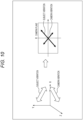
- the frequency information can also be calculated by restoring a luminance change for each pixel on the basis of a time series of a polarity included in event data.
- a left graph in Fig. 9 illustrates an example of a luminance change at a predetermined pixel position (x, y).
- event data is output when a luminance value changes by a predetermined threshold value or more.
- a luminance value of a pixel increases by a threshold value Lth or more at each of times t 1 , t 2 , and t 3
- the luminance value of the pixel decreases by the threshold value Lth or more at each of times t 4 and t 5 . That is, an event with the polarity indicated by the upward arrow in Fig. 3 occurs at each of the times t 1 , t 2 , and t 3
- an event with the polarity indicated by the downward arrow in Fig. 3 occurs at each of the times t 4 and t 5 .
- an occurrence of the event with the polarity indicated by the upward arrow is defined as addition of the luminance value by an amount of the threshold value Lth
- an occurrence of the event with the polarity indicated by the downward arrow is defined as subtraction of the luminance value by an amount of the threshold value Lth.
- the frequency calculation unit 31 restores the luminance change for each pixel as illustrated in Fig. 9 , on the basis of a time series of the polarity included in the event data. Then, the frequency calculation unit 31 can calculate frequency information by performing frequency analysis on the restored luminance change, by using fast Fourier transform (FFT).
- FFT fast Fourier transform
- the threshold value Lth set in the EVS 11 is smaller, the luminance change can be restored more accurately.
- the threshold value Lth is reduced, noise is also increased. Therefore, noise removal processing may be performed on the restored luminance change.
- vibration detected by the vibration detection unit 30 includes a mixture of vibration of the subject and vibration of the EVS camera 10. In this case, in order to detect only the vibration of the subject, it is necessary to perform frequency separation on the vibration detected by the vibration detection unit 30.
- the EVS camera 10 is calibrated in an image-capturing direction in which the subject vibration and the camera vibration can be separated.
- the EVS camera 10 is calibrated in an image-capturing direction in which the subject vibration and the camera vibration projected on a camera plane are orthogonal to each other.
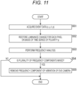
- Fig. 11 is a flowchart illustrating a flow of frequency separation using a luminance change for each pixel restored on the basis of event data.
- step S51 the vibration detection unit 30 acquires event data (x, y, t, p) input from the input unit 21.
- event data for each pixel in which an event (a luminance change in the pixel) has occurred is output in units of ⁇ seconds.
- event data for a certain period is acquired.
- step S52 as described with reference to Fig. 9 , the frequency calculation unit 31 restores a luminance change for each pixel on the basis of a time series of the polarity p included in the acquired event data.
- step S53 the frequency calculation unit 31 performs frequency analysis on the restored luminance change.
- step S54 the frequency calculation unit 31 determines whether or not a plurality of frequency components (specifically, two frequency components) is mixed in a result of the frequency analysis. When it is determined that a plurality of frequency components is mixed, the processing proceeds to step S55.
- a plurality of frequency components specifically, two frequency components
- step S55 the frequency calculation unit 31 removes a frequency component of vibration of the EVS camera 10 from the plurality of frequency components.
- the frequency component of the vibration of the EVS camera 10 is obtained by detecting vibration of the EVS camera 10 from event data obtained by capturing an image of a stationary subject with the vibrating EVS camera 10 in advance.
- step S55 is skipped.
- the result of the frequency analysis is a frequency of vibration of the subject or a frequency of vibration of the EVS camera 10.
- the frequency separation can be performed on the basis of a luminance change for each pixel restored on the basis of the event data.
- the vibration detection unit 30 is implemented by the processing unit 22 of the information processing apparatus 20 configured as a computer, but may be implemented inside the EVS camera.
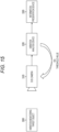
- Fig. 12 is a diagram illustrating a configuration example of an EVS camera which is one of embodiments of the present disclosure.
- An EVS camera 210 of Fig. 12 includes an event-based vision sensor (EVS) 211 and a processing unit 212.
- EVS event-based vision sensor
- the EVS 211 detects a luminance change in a pixel as an event, and outputs event data for each pixel in which an event has occurred.
- the processing unit 212 includes a processor such as a CPU.
- the processing unit 212 implements the vibration detection unit 30 by executing a predetermined program. Vibration information generated by the vibration detection unit 30 and indicating a vibration state of a subject is output to an external device or the like connected to the EVS camera 210.
- the processor constituting the processing unit 212 may be integrated into one chip together with the EVS 211, or may be mounted on a companion chip or the like electrically connected to the EVS 211, for example.
- the processing unit 212 is mounted on a companion chip different from the EVS 211, as illustrated in Fig. 13 , the EVS 211 and a companion chip 231 can also be electrically connected to each other by being stacked.
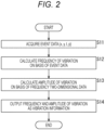
- Fig. 14 is a diagram illustrating a configuration example of a failure prediction system.
- the failure prediction system in Fig. 14 monitors vibration of a vibration monitoring target object 300 to predict the presence or absence of a failure of the vibration monitoring target object 300.
- the vibration monitoring target object 300 is, for example, multiple pieces of equipment and device installed in a factory or the like.
- the failure prediction system in Fig. 14 includes an EVS camera 310, a vibration analysis device 320, and an information presentation device 330.
- the EVS camera 310 corresponds to the EVS camera 10 in Fig. 1
- the vibration analysis device 320 and the information presentation device 330 correspond to the information processing apparatus 20 in Fig. 1 .
- the vibration analysis device 320 analyzes vibration of the vibration monitoring target object 300 on the basis of event data from the EVS camera 310. For example, the vibration analysis device 320 analyzes vibration of the vibration monitoring target object 300 by using a method such as time series analysis or an abnormality detection algorithm.
- the information presentation device 330 presents information based on an analysis result of vibration obtained by the vibration analysis device 320. For example, in a case where abnormal vibration is detected in a part of the vibration monitoring target object 300, the information presentation device 330 performs, for example, emphasis display on a portion where abnormal vibration is detected or surrounds the portion with a frame, in a frequency image obtained by visualizing frequency two-dimensional data generated by the vibration analysis device 320. Furthermore, in this case, the information presentation device 330 may output a predetermined alarm by display or sound.
- the vibration analysis device 320 may feed back a control parameter for controlling the vibration monitoring target object 300, to the vibration monitoring target object 300.
- the control parameter is, for example, a current value, a voltage value, or the like for driving the vibration monitoring target object 300.
- the vibration analysis device 320 may feed back a region of interest (ROI) and a threshold value for outputting event data, to the EVS camera 310.
- ROI region of interest
- the EVS camera 310 can perform image-capturing with a pixel region where an event has occurred as a center, and can output the event data more efficiently.
- the EVS camera 310 can more appropriately output event data for a luminance change, and it is possible to prevent erroneous detection and detection omission of vibration.
- Fig. 16 is a diagram illustrating a configuration example of a minute vibration detection system.
- the minute vibration detection system in Fig. 16 monitors minute vibration of a vibration monitoring target object 400.
- the minute vibration detection system in Fig. 16 includes an EVS camera 410, a vibration detection device 420, and an active light source 430.
- the EVS camera 410 corresponds to the EVS camera 10 in Fig. 1
- the vibration detection device 420 corresponds to the information processing apparatus 20 in Fig. 1 .
- the vibration detection device 420 detects vibration of the vibration monitoring target object 400 on the basis of event data from the EVS camera 410.
- the active light source 430 irradiates, with light, a surface of the vibration monitoring target object 400 that vibrates with a minute amplitude.
- the EVS camera 410 captures an image of, as a subject, reflected light reflected by the surface of the vibration monitoring target object 400.
- an amplitude w of vibration of the vibration monitoring target object 400 is a change within one pixel in an image-capturing range of the EVS camera 410, the vibration is not detected even if an image of the vibration monitoring target object 400 is captured as a subject.
- vibration of the vibration monitoring target object 400 can be detected.
- a vibration direction of the vibration monitoring target object 400 is not specified.
- the series of processing described above can be executed by hardware or software.
- a program which forms the software is installed on a computer.
- examples of the computer include a computer incorporated in dedicated hardware and, for example, a general-purpose personal computer capable of executing various functions when various programs are installed.
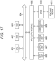
- Fig. 17 is a block diagram illustrating a configuration example of hardware of a computer that executes the series of processing described above by a program.
- a CPU 601 In the computer, a CPU 601, a read only memory (ROM) 602, and a random access memory (RAM) 603 are mutually connected by a bus 604.
- ROM read only memory
- RAM random access memory
- An input-output interface 605 is further connected to the bus 604.
- An input unit 606, an output unit 607, a storage unit 608, a communication unit 609, and a drive 610 are connected to the input-output interface 605.
- the input unit 606 includes a keyboard, a mouse, a microphone, and the like.
- the output unit 607 includes a display, a speaker, and the like.
- the storage unit 608 includes a hard disk, a nonvolatile memory, and the like.
- the communication unit 609 includes a network interface and the like.
- the drive 610 drives a removable medium 611 such as a magnetic disk, an optical disk, a magneto-optical disk, or a semiconductor memory.
- the CPU 601 loads a program, for example, stored in the storage unit 608 into the RAM 603 via the input-output interface 605 and the bus 604 and executes the program, whereby the above-described series of processing is performed.
- a program for example, stored in the storage unit 608 into the RAM 603 via the input-output interface 605 and the bus 604 and executes the program, whereby the above-described series of processing is performed.
- the program executed by the computer (CPU 601) can be provided by being recorded in the removable medium 611 as a package medium or the like, for example. Furthermore, the program can be provided via a wired or wireless transmission medium such as a local area network, the Internet, or digital satellite broadcasting.
- the program can be installed in the storage unit 608 via the input-output interface 605 by mounting the removable medium 611 to the drive 610. Furthermore, the program can be received by the communication unit 609 via a wired or wireless transmission medium, and installed on the storage unit 608. Furthermore, the program can be installed in the ROM 602 or the storage unit 608 in advance.
- the program executed by the computer may be a program in which processing is performed in time series in the order described in the present specification, or may be a program in which processing is performed in parallel or at necessary timing such as when a call is made or the like.
- the present disclosure can also have the following configurations.
Landscapes
- Engineering & Computer Science (AREA)
- Multimedia (AREA)
- Signal Processing (AREA)
- Physics & Mathematics (AREA)
- General Physics & Mathematics (AREA)
- Measurement Of Mechanical Vibrations Or Ultrasonic Waves (AREA)
Applications Claiming Priority (2)
| Application Number | Priority Date | Filing Date | Title |
|---|---|---|---|
| JP2021036012 | 2021-03-08 | ||
| PCT/JP2022/001100 WO2022190622A1 (ja) | 2021-03-08 | 2022-01-14 | 情報処理装置、情報処理方法、およびプログラム |
Publications (2)
| Publication Number | Publication Date |
|---|---|
| EP4306918A1 true EP4306918A1 (de) | 2024-01-17 |
| EP4306918A4 EP4306918A4 (de) | 2024-08-07 |
Family
ID=83227267
Family Applications (1)
| Application Number | Title | Priority Date | Filing Date |
|---|---|---|---|
| EP22766590.8A Pending EP4306918A4 (de) | 2021-03-08 | 2022-01-14 | Informationsverarbeitungsvorrichtung, informationsverarbeitungsverfahren und programm |
Country Status (5)
| Country | Link |
|---|---|
| US (1) | US12489992B2 (de) |
| EP (1) | EP4306918A4 (de) |
| JP (1) | JPWO2022190622A1 (de) |
| TW (1) | TW202300875A (de) |
| WO (1) | WO2022190622A1 (de) |
Families Citing this family (4)
| Publication number | Priority date | Publication date | Assignee | Title |
|---|---|---|---|---|
| JP7793301B2 (ja) * | 2021-06-10 | 2026-01-05 | キヤノン株式会社 | 情報処理装置、情報処理方法およびプログラム |
| EP4684389A2 (de) * | 2023-03-23 | 2026-01-28 | Sony Group Corporation | Elektronische vorrichtung, verfahren und computerprogramm |
| WO2024199931A1 (en) * | 2023-03-24 | 2024-10-03 | Sony Semiconductor Solutions Corporation | Sensor device and method for operating a sensor device |
| WO2025041256A1 (ja) * | 2023-08-22 | 2025-02-27 | 日本電信電話株式会社 | 音響計測装置、音響計測システム、音響計測方法及びプログラム |
Family Cites Families (8)
| Publication number | Priority date | Publication date | Assignee | Title |
|---|---|---|---|---|
| KR102359907B1 (ko) * | 2014-12-27 | 2022-02-08 | 가디언 옵티컬 테크놀로지스 엘티디. | 표면 진동 감지 시스템 및 방법 |
| CN108574793B (zh) * | 2017-03-08 | 2022-05-10 | 三星电子株式会社 | 被配置为重新生成时间戳的图像处理设备及包括其在内的电子设备 |
| WO2019064968A1 (ja) * | 2017-09-29 | 2019-04-04 | 富士フイルム株式会社 | 投影装置および投影方法 |
| KR102535839B1 (ko) * | 2018-09-14 | 2023-05-24 | 삼성전자주식회사 | 안테나 어레이를 이용하여 외부 객체를 감지하는 전자 장치 및 그의 동작 방법 |
| WO2020120782A1 (en) * | 2018-12-13 | 2020-06-18 | Prophesee | Method of tracking objects in a scene |
| EP3690736A1 (de) * | 2019-01-30 | 2020-08-05 | Prophesee | Verfahren zur verarbeitung von informationen aus einem ereignisbasierten sensor |
| WO2020216953A1 (en) * | 2019-04-25 | 2020-10-29 | Prophesee Sa | Systems and methods for imaging and sensing vibrations |
| JP6842126B2 (ja) | 2019-05-10 | 2021-03-17 | 国立大学法人広島大学 | 振動解析システム、振動解析方法及びプログラム |
-
2022
- 2022-01-14 US US18/263,657 patent/US12489992B2/en active Active
- 2022-01-14 EP EP22766590.8A patent/EP4306918A4/de active Pending
- 2022-01-14 JP JP2023505155A patent/JPWO2022190622A1/ja not_active Abandoned
- 2022-01-14 WO PCT/JP2022/001100 patent/WO2022190622A1/ja not_active Ceased
- 2022-03-01 TW TW111107247A patent/TW202300875A/zh unknown
Also Published As
| Publication number | Publication date |
|---|---|
| US12489992B2 (en) | 2025-12-02 |
| EP4306918A4 (de) | 2024-08-07 |
| WO2022190622A1 (ja) | 2022-09-15 |
| JPWO2022190622A1 (de) | 2022-09-15 |
| US20240073552A1 (en) | 2024-02-29 |
| TW202300875A (zh) | 2023-01-01 |
Similar Documents
| Publication | Publication Date | Title |
|---|---|---|
| EP4306918A1 (de) | Informationsverarbeitungsvorrichtung, informationsverarbeitungsverfahren und programm | |
| EP2677500B1 (de) | Ereignisbasierte bildverarbeitungsvorrichtung und zugehöriges verfahren | |
| US11521312B2 (en) | Image processing apparatus, image processing method, and storage medium | |
| US20030234347A1 (en) | Monitor | |
| JPWO2018043251A1 (ja) | 欠陥検出装置、欠陥検出方法、及びコンピュータ読み取り可能記録媒体 | |
| JP7222231B2 (ja) | 行動認識装置、行動認識方法及びプログラム | |
| US20220373683A1 (en) | Image processing device, monitoring system, and image processing method | |
| JPWO2017037896A1 (ja) | 異常検知装置、異常検知方法、及び異常検知プログラム | |
| US11521330B2 (en) | Image processing apparatus, image processing method, and storage medium | |
| EP3193153A1 (de) | Vorrichtung zur fehlererkennung bei einer drehmaschine, verfahren und system sowie drehmaschine | |
| CN114549820B (zh) | 传输带的运动检测方法、检测设备、电子设备和介质 | |
| WO2020162426A1 (ja) | 解析装置、解析方法、およびプログラム、ならびに、センサの構造 | |
| US10525900B2 (en) | Vehicle periphery monitoring device | |
| JP2006293820A (ja) | 外観検査装置、外観検査方法およびコンピュータを外観検査装置として機能させるためのプログラム | |
| WO2020255728A1 (ja) | 振動計測装置、振動計測方法、及びコンピュータ読み取り可能な記録媒体 | |
| KR100950463B1 (ko) | 엔티에스씨/피에이엘 카메라용 영상 추적 칩 개발 장치 | |
| JP2012133433A (ja) | 置去り/持去り物体検知装置及び置去り/持去り物体検知方法 | |
| TWI729322B (zh) | 資訊顯示系統及資訊顯示方法 | |
| US12050183B2 (en) | Abnormality determination device, abnormality determination method, and program storage medium | |
| EP4099264A1 (de) | Lernvorrichtung und lernverfahren | |
| US20220130026A1 (en) | Wire non-attachment inspection system, wire non-attachment detection device, and wire non-attachment detection method | |
| US20230196840A1 (en) | Work management device and work state determination method | |
| JP4977238B2 (ja) | ケーブル弛み検知装置、ケーブル弛み検知方法およびケーブル弛み検知プログラム | |
| Muralidharan et al. | Comparative Study of Vision Camera-based Vibration Analysis with the Laser Vibrometer Method | |
| Wang et al. | HFR-video-based machinery surveillance for high-speed periodic operations |
Legal Events
| Date | Code | Title | Description |
|---|---|---|---|
| STAA | Information on the status of an ep patent application or granted ep patent |
Free format text: STATUS: THE INTERNATIONAL PUBLICATION HAS BEEN MADE |
|
| PUAI | Public reference made under article 153(3) epc to a published international application that has entered the european phase |
Free format text: ORIGINAL CODE: 0009012 |
|
| STAA | Information on the status of an ep patent application or granted ep patent |
Free format text: STATUS: REQUEST FOR EXAMINATION WAS MADE |
|
| 17P | Request for examination filed |
Effective date: 20230930 |
|
| AK | Designated contracting states |
Kind code of ref document: A1 Designated state(s): AL AT BE BG CH CY CZ DE DK EE ES FI FR GB GR HR HU IE IS IT LI LT LU LV MC MK MT NL NO PL PT RO RS SE SI SK SM TR |
|
| DAV | Request for validation of the european patent (deleted) | ||
| DAX | Request for extension of the european patent (deleted) | ||
| A4 | Supplementary search report drawn up and despatched |
Effective date: 20240705 |
|
| RIC1 | Information provided on ipc code assigned before grant |
Ipc: G01M 99/00 20110101ALI20240701BHEP Ipc: G01H 9/00 20060101AFI20240701BHEP |
|
| STAA | Information on the status of an ep patent application or granted ep patent |
Free format text: STATUS: EXAMINATION IS IN PROGRESS |
|
| 17Q | First examination report despatched |
Effective date: 20250321 |