EP4306723A1 - Electric work machine - Google Patents
Electric work machine Download PDFInfo
- Publication number
- EP4306723A1 EP4306723A1 EP22315154.9A EP22315154A EP4306723A1 EP 4306723 A1 EP4306723 A1 EP 4306723A1 EP 22315154 A EP22315154 A EP 22315154A EP 4306723 A1 EP4306723 A1 EP 4306723A1
- Authority
- EP
- European Patent Office
- Prior art keywords
- electric
- electric motor
- work machine
- hydraulic
- cooling device
- Prior art date
- Legal status (The legal status is an assumption and is not a legal conclusion. Google has not performed a legal analysis and makes no representation as to the accuracy of the status listed.)
- Pending
Links
Images




Classifications
-
- E—FIXED CONSTRUCTIONS
- E02—HYDRAULIC ENGINEERING; FOUNDATIONS; SOIL SHIFTING
- E02F—DREDGING; SOIL-SHIFTING
- E02F9/00—Component parts of dredgers or soil-shifting machines, not restricted to one of the kinds covered by groups E02F3/00 - E02F7/00
- E02F9/08—Superstructures; Supports for superstructures
- E02F9/0858—Arrangement of component parts installed on superstructures not otherwise provided for, e.g. electric components, fenders, air-conditioning units
- E02F9/0866—Engine compartment, e.g. heat exchangers, exhaust filters, cooling devices, silencers, mufflers, position of hydraulic pumps in the engine compartment
-
- E—FIXED CONSTRUCTIONS
- E02—HYDRAULIC ENGINEERING; FOUNDATIONS; SOIL SHIFTING
- E02F—DREDGING; SOIL-SHIFTING
- E02F9/00—Component parts of dredgers or soil-shifting machines, not restricted to one of the kinds covered by groups E02F3/00 - E02F7/00
- E02F9/20—Drives; Control devices
- E02F9/2058—Electric or electro-mechanical or mechanical control devices of vehicle sub-units
- E02F9/2062—Control of propulsion units
- E02F9/207—Control of propulsion units of the type electric propulsion units, e.g. electric motors or generators
-
- E—FIXED CONSTRUCTIONS
- E02—HYDRAULIC ENGINEERING; FOUNDATIONS; SOIL SHIFTING
- E02F—DREDGING; SOIL-SHIFTING
- E02F9/00—Component parts of dredgers or soil-shifting machines, not restricted to one of the kinds covered by groups E02F3/00 - E02F7/00
- E02F9/20—Drives; Control devices
- E02F9/22—Hydraulic or pneumatic drives
- E02F9/226—Safety arrangements, e.g. hydraulic driven fans, preventing cavitation, leakage, overheating
Definitions
- the present invention relates to an electric work machine.
- Patent Document 1 discloses a backhoe equipped with an electric motor.
- the above backhoe adopts a layout in which a hydraulic pump, an electric motor, and a fan for cooling (air-cooling) the above are located below a battery (energy storage device).
- Patent Document 1 Japanese Unexamined Patent Application Publication No. 2011-089369
- a cooling device including a heat exchanger should be located thereby to cool at least one of a refrigerant that passes through an electric instrument (e.g., electric motor) and a hydraulic oil supplied from a hydraulic pump to a hydraulic actuator.
- an electric instrument e.g., electric motor
- a hydraulic oil supplied from a hydraulic pump to a hydraulic actuator.
- the present invention has been made so as to solve the above problem; it is therefore an object of the present invention to compactly locating an energy storage device, a cooling device, and an electric motor thereby to realize a layout preferable for a small electric work machine.
- An electric work machine includes: an electric motor, an energy storage device that stores electric power to drive the electric motor, a hydraulic pump that is driven by the electric motor and discharges a hydraulic oil, and an electric instrument through which a refrigerant passes, wherein the electric work machine further includes a cooling device that cools at least one of the hydraulic oil and the refrigerant, and the electric motor and the cooling device are located beside the energy storage device.
- the energy storage device, the cooling device, and the electric motor can be compactly located thereby to realize a layout preferable for a small electric work machine.
- FIG. 1 is a side view showing a schematic configuration of a hydraulic excavator 1 which is an example of an electric work machine according to the present embodiment.
- the hydraulic excavator 1 is equipped with a lower travel body 2, work instrument 3, and an upper swivel body 4.
- directions are defined as follows.
- the direction in which a man operator (pilot, driver) seated in a driver seat 41a of the upper swivel body 4 faces the front is forward, and the opposite direction is backward. Therefore, when the upper swivel body 4 is in a non-swivel state (swivel angle 0°) relative to the lower travel body 2, the front-back direction of the upper swivel body 4 is the same as the direction in which the lower travel body 2 moves forward and backward. Also, the left side is "left” and the right side is "right” as viewed from the man operator seated in the driver seat 41a.
- the gravity direction perpendicular to the front-back and left-right directions is defined as the vertical direction, with the upstream side of the gravity direction being “up” and the downstream side being “down.”
- the hydraulic excavator 1 is shown with the upper swivel body 4 in a non-swivel position relative to the lower travel body 2.
- forward is denoted by a symbol "F”, likewise, backward by "B”, rightward by “R”, leftward by “L”, upward by "U”, and downward by "D".
- the lower travel body 2 is equipped with a pair of crawlers 21 on left and right and a pair of traveling motors 22 on left and right.
- Each of the traveling motors 22 is a hydraulic motor.
- the left and right traveling motors 22 drive the left and right crawlers 21, respectively, thereby to move the hydraulic excavator 1 forward and backward.
- the lower travel body 2 is equipped with a blade 23 and a blade cylinder 23a for leveling work.
- the blade cylinder 23a is a hydraulic cylinder to rotate the blade 23 in the vertical direction.
- the work instrument 3 has a boom 31, an arm 32, and a bucket 33.
- the boom 31, the arm 32, and the bucket 33 are driven independently there to make it possible to perform excavating of earth and sand.
- the boom 31, the arm 32, and the bucket 33 are rotated by an unshown boom cylinder, an unshown arm cylinder, and an unshown bucket cylinder, respectively.
- the boom cylinder, the arm cylinder, and the bucket cylinder are each constituted of a hydraulic cylinder.
- a base end portion of the boom 31, i.e., the end portion opposite the side connected to the arm 32 in the boom 31 is swingably connected to a head end portion 42a of a swivel frame 42 via a bracket 34. That is, the hydraulic excavator 1 in the present embodiment has a boom swing function in which the boom 31 swings to the left or right starting from the head end portion 42a.
- the upper swivel body 4 is located above the lower travel body 2 and can be swiveled with respect to the lower travel body 2 via a swivel bearing (not shown).
- a swivel bearing (not shown).
- an operating portion 41, a swivel frame 42, a swivel motor 43, an engine chamber 44, etc. are located in the upper swivel body 4. Being driven with the swivel motor 43 as a hydraulic motor, the upper swivel body 4 swivels via a swivel bearing.
- a hydraulic pump 71 (see FIG. 2 ) is located in the upper swivel body 4.
- the hydraulic pump 71 is driven by an electric motor 61 (see FIG. 2 ) inside the engine chamber 44.
- the hydraulic pump 71 supplies hydraulic oil (pressure oil) to the hydraulic motor (e.g., left and right traveling motors 22, swivel motor 43), and the hydraulic cylinder (e.g., blade cylinder 23a, boom cylinder, arm cylinder, bucket cylinder).
- the hydraulic motor and the hydraulic cylinder that are driven with the hydraulic oil supplied from the hydraulic pump 71 are collectively referred to as a hydraulic actuator 73 (see FIG. 2 ).
- the driver seat 41a is located in the operating portion 41.
- Various levers 41b are located around the driver seat 41a.
- the hydraulic actuator 73 is driven. This allows the lower travel body 2 to travel, the blade 23 to perform the ground leveling work, the work instrument 3 to perform the excavation work, and the upper swivel body 4 to swivel, etc.
- a battery unit 53 is located in the upper swivel body 4. That is, the hydraulic excavator 1 is equipped with the battery unit 53.
- the battery unit 53 is constituted of a lithium-ion battery unit, for example, and is an energy storage device that stores power to drive the electric motor 61.
- the battery unit 53 may be constituted of a plurality of battery cells as a unit or may be constituted of a single battery cell.
- a power feed port 50 (see FIG. 3 ) is provided at the back portion of the upper swivel body 4. The power feed port 50, and a commercial power source 51 as an external power source are connected via a power feed cable 52. This can charge the battery unit 53.
- the upper swivel body 4 is further equipped with a lead battery 54.
- the lead battery 54 outputs a low-voltage (e.g., 12 V) DC voltage.
- the output from the lead battery 54 is supplied as control voltage to, for example, a system controller 67 (see FIG. 2 ), a driver of a fan 92 (see FIG. 4 ), etc.
- the hydraulic excavator 1 may be so configured as to be a combination of a hydraulic instrument such as a hydraulic actuator 73 and an actuator driven by electric power.
- Actuators driven by electric power include, for example, electric travel motors, electric cylinders, and electric swivel motors.
- FIG. 2 is a block diagram schematically showing the electric and hydraulic systems of the hydraulic excavator 1.
- the hydraulic excavator 1 has the electric motor 61, a charger 62, an inverter 63, a PDU (Power Distribution Unit) 64, a junction box 65, a DC-DC converter 66, and the system controller 67.
- the system controller 67 is constituted of an electronic control unit, also called an ECU (Electronic Control Unit), and electrically controls each part of the hydraulic excavator 1.
- ECU Electronic Control Unit
- the electric motor 61 is driven by electric power supplied from the battery unit 53 via the junction box 65 and the inverter 63.
- the electric motor 61 is constituted of a permanent magnet motor or an induction motor.
- On the swivel frame 42, the electric motor 61 is supported by a motor support portion 100 (see FIG. 3 , etc.).
- the charger 62 (also called a power feeder) converts AC voltage supplied from the commercial power source 51, shown in FIG. 1 , via the power feed cable 52.
- the inverter 63 converts the DC voltage supplied from the battery unit 53, and supplies the AC voltage to the electric motor 61. This rotates the.electric motor 61.
- the AC voltage (current) is supplied from the inverter 63 to the electric motor 61 based on the rotation command output from the system controller 67.
- the PDU64 is a battery control unit that controls an internal battery relay thereby to control the inputting and outputting of the battery unit 53.
- the PDU 64 is located above the battery unit 53 (see FIG. 4 ).
- the junction box 65 includes a charger relay, an inverter relay, a fuse, etc.
- the voltage output from the charger 62 is supplied to the battery unit 53 via the junction box 65 and the PDU 64. Further, the voltage output from the battery unit 53 is supplied to the inverter 63 via the PDU 64 and the junction box 65.
- the DC-DC converter 66 steps down the high-voltage (e.g., 300 V) DC voltage supplied from the battery unit 53 via the junction box 65. Like the output from the lead battery 54, the voltage output from the DC-DC converter 66 is supplied to the system controller 67, the driver of the fan 92, etc. Note that the DC-DC converter 66 may be located within the PDU 64.
- a plurality of hydraulic pumps 71 are connected to the rotary shaft (output shaft) of the electric motor 61.
- the plurality of hydraulic pumps 71 include variable displacement and fixed displacement pumps.
- FIG. 2 shows one hydraulic pump 71 only as an example.
- Each hydraulic pump 71 is connected to a hydraulic oil tank 74.
- the control valve 72 is a direction-switching valve that controls the flow direction and flow rate of the hydraulic oil supplied from the hydraulic pump 71 to the hydraulic actuator 73.
- the hydraulic excavator 1 is equipped with the hydraulic pump 71 that is driven by the electric motor 61 and discharges the hydraulic oil. Also, the hydraulic excavator 1 is equipped with the hydraulic actuator 73 driven by the hydraulic oil supplied from the hydraulic pump 71. In addition, the hydraulic excavator 1 is equipped with a hydraulic oil tank 74 that contains the hydraulic oil.
- the electric instrument EL such as the battery unit 53, the electric motor 61, and the inverter 63 are connected to a radiator 91a (see FIG. 3 ) to be described below.
- Refrigerant supplied from the radiator 91a flows in the piping RP.
- the refrigerant flowing in the piping RP passes through in the electric instrument EL. Therefore, cooling the refrigerant by heat exchange in the radiator 91a and supplying the refrigerant from the radiator 91a to the electric instrument EL can cool (water-cool) the electric instrument EL.
- the hydraulic excavator 1 is equipped with the electric instrument EL through which the refrigerant passes.
- the refrigerant is, for example, cooling water.
- FIG. 3 is a back perspective view of the overall configuration in the engine chamber 44 of the hydraulic excavator 1.
- the driver seat 41a is located on a seat mount 81.
- the battery unit 53 is located between the seat mount 81 and the swivel frame 42.
- the battery unit 53 is located on the swivel frame 42, on the back side, and off to the left of the center in the left-right direction.
- two battery cells 53a are vertically located alongside thereby to form one battery unit 53.
- the number of battery cells 53a constituting the battery unit 53 is not particularly limited.
- Behind the battery unit 53 on the swivel frame 42, the lead battery 54 and the power feed port 50 are located alongside the left-right direction.
- the charger 62 is located at the upper back portion of the battery unit 53.
- a cooling device 90 is located to the right of the battery unit 53. That is, the hydraulic excavator 1 is equipped with the cooling device 90.
- the cooling device 90 is a device that cools at least one of the refrigerant and the hydraulic oil by the heat exchange.
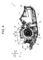
- FIG. 4 is a back perspective view of the main portion in the engine chamber 44 of the hydraulic excavator 1.
- the cooling device 90 includes a heat exchanger 91, the fan 92, and a fan shroud 93.
- the heat exchanger 91 includes a radiator 91a and an oil cooler 91b.
- the radiator 91a cools the refrigerant passing through the electric instrument EL.
- the oil cooler 91b is connected to an oil path circulating via the hydraulic pump 71, the hydraulic actuator 73 (see Fig. 2 ), etc., and, by the heat exchange, cools the hydraulic oil flowing in the oil path.
- the radiator 91a and the oil cooler 91b are located alongside the front-back direction. Further, the radiator 91a and the oil cooler 91b are located opposite the fan 92.
- the fan 92 generates airflow across the heat exchanger 91.
- the fan 92 is located on the right side of the heat exchanger 91, i.e., opposite the battery unit 53 with respect to the heat exchanger 91.
- the fan 92 is covered with the fan shroud 93.
- the fan shroud 93 is a cover having an air vent 93a, and covers the fan 92 from the right side.
- the drive type of fan 92 may be a "sucking type".
- sucking type when the fan 92 is rotated, air outside the hydraulic excavator 1 is sucked into the engine chamber 44 through the air vent 93a of the fan shroud 93.
- the air sucked in by the fan 92 flows toward the heat exchanger 91, and runs across the heat exchanger 91. This cools the heat exchanger 91.
- the heat exchanger 91 is constituted of only one of the radiator 91a and the oil cooler 91b, and the other is located in a different position and cooled by a separate fan.
- the heat exchanger 91 should include both the radiator 91a and the oil cooler 91b, in the respect that one fan 92 can cool both the radiator 91a and the oil cooler 91b simultaneously (efficiently).
- the above hydraulic oil tank 74 is located forward of the cooling device 90 on the swivel frame 42. Then, on the swivel frame 42, and between the cooling device 90 and the hydraulic oil tank 74, the electric motor 61 and hydraulic pump 71 are located.
- the electric motor 61 is supported on the swivel frame 42 by the motor support portion 100.
- the hydraulic excavator 1 is equipped with the motor support portion 100 that supports the electric motor 61 on the swivel frame 42 as a machine body frame. Details of the motor support portion 100 are to be described below.
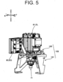
- FIG. 5 shows a perspective view of the motor support portion 100 with the electric motor 61 being supported.
- FIG. 6 is a perspective view of the motor support portion 100 alone.
- the motor support portion 100 has a first support portion 101 and a second support portion 102. With bolts and nuts (hereinafter referred to as “bolts, etc.”), the first support portion 101 is attached to the swivel frame 42 (see FIG. 4 ) as the machine body frame.
- the second support portion 102 is located above the first support portion 101 and supports the electric motor 61.
- the second support portion 102 is attached to the first support portion 101. This allows the second support portion 102 to be supported by the first support portion 101.
- the fasteners 103 include, for example, bolts, nuts, and anti-vibration rubber.
- the first support portion 101 has an upper plate portion 111, a leg portion 112.
- the upper plate portion 111 is a flat plate extending in the left-right and front-back directions, and, on the inside thereof, has an upper plate opening portion 111a through which the hydraulic pump 71 (see FIG. 5 ) passes.
- the leg portion 112 includes a first leg portion 112a and a second leg portion 112b.
- the first leg portion 112a is connected to the right side edge portion of the upper plate portion 111, is narrower downward in width in the front-back direction, and has a lower end portion bending to the left side.
- the lower end portion of the first leg portion 112a is fixed to the swivel frame 42 with bolts or the like.
- the second leg portion 112b has a front leg portion 112b1 and a back leg portion 112b2.
- Upper end portions of the front leg portion 112b1 and the back leg portion 112b2 are connected to the front and back of the left side edge portion of the upper plate portion 111, respectively.
- the front leg portion 112b1 and the back leg portion 112b2 narrow their distance from each other downward and meet (merge) in one place.
- Lower end portions of the front leg portion 112b1 and back leg portion 112b2, that is, merging end portions are bent to the right, and fixed to the swivel frame 42 with bolts or the like. This attaches the first support portion 101 to the swivel frame 42.
- the second support portion 102 has a bottom plate portion 121, and a fixing plate portion 122.
- the bottom plate portion 121 is a flat plate extending in the left-right and front-back directions, and, on the inside thereof, has a bottom plate opening portion 121a through which the hydraulic pump 71 (see FIG. 5 ) passes.
- the fixing plate portion 122 is a flat plate caused to stand on the left edge portion of the bottom plate portion 121.
- the angle defined between the bottom plate portion 121 and the fixing plate portion 122 is substantially 90°.
- the electric motor 61 (see Fig. 5 ) is fixed to the fixing plate portion 122 with bolts or the like.
- the output shaft of the electric motor 61 is located along the vertical direction. That is, the electric motor 61 is fixed to the fixing plate portion 122 with the output shaft facing up and down.
- the electric motor 61 is fixed to the fixing plate portion 122 in a manner to be located above the bottom plate portion 121. Therefore, with the electric motor 61 fixed to the fixing plate portion 122, the bottom plate portion 121 is located lower than the electric motor 61. That is, the motor support portion 100 has the bottom plate portion 121 located below the electric motor 61.
- the fixing plate portion 122 extends backward (cooling device 90 side) from the bottom plate portion 121.
- the inverter 63 as an electric component EQ is attached with bolts or the like.
- the electric component EQ is located alongside the electric motor 61 in the front-back direction.
- the fixing plate portion 122 is located between the electric motor 61 and the battery unit 53 (see Fig. 9 ).
- the fixing plate portion 122 has a first opening portion 122a and a second opening portion 122b provided alongside the front-back direction.
- the first opening portion 122a and the second opening portion 122b are openings for heat dissipation of the electric motor 61 and inverter 63, and are formed corresponding to positions of mounting the electric motor 61 and the inverter 63.
- the electric component EQ to be fixed to the fixing plate portion 122 is not limited to the inverter 63, and may be, for example, the DC-DC converter 66 (see FIG. 2 ). However, since the inverter 63 supplies a high voltage to the electric motor 61, it is preferable to place the inverter 63 and the electric motor 61 together (close to each other) so as to facilitate the arrangement of these connecting cables.
- Reinforcing members 123 are provided at the front and back edges of the bottom plate portion 121. Each reinforcement member 123 extends diagonally leftward and upward from the bottom plate portion 121, and has an end connected to the fixing plate portion 122, respectively. This reinforces the fixing plate portion 122 to the bottom plate portion 121.
- FIG. 7 is a perspective view showing the positional relationship between the hydraulic pump 71 and the motor support portion 100.
- FIG. 7 omits the electric motor 61 to which the hydraulic pump 71 is connected.
- the hydraulic pump 71 Penetrating through the bottom plate opening portion 121a and the upper plate opening portion 111a of the motor support portion 100, the hydraulic pump 71 is connected to the electric motor 61. Since the output shaft of the electric motor 61 is along the vertical direction as described above, the input shaft of the hydraulic pump 71, which is connected to the output shaft, is also along the vertical direction.
- the hydraulic pump 71 is not supported by the motor support portion 100, but is connected (directly) to the electric motor 61 and suspended in midair.
- a support member to support the hydraulic pump 71 on the swivel frame 42 may be separately provided.
- Mounting the electric motor 61 to the swivel frame 42 using the motor support portion 100 is performed, for example, in the following procedure.
- (1) The output shaft of the electric motor 61 is connected to the input shaft of the hydraulic pump 71 via a coupling (not shown).
- With a fastener 103 connect the second support portion 102 and the first support portion 101.
- the hydraulic pump 71 is located in a manner to pass through the upper plate opening portion 101a of the first support portion 101.
- the order of (2) and (3) may be reversed.
- the order of (4) and (5) may be reversed.
- FIG. 8 is a plan view showing the configuration of the main portion in the engine chamber 44 of the hydraulic excavator 1.
- FIG. 9 is a schematic plan view of the configuration in FIG. 8 .
- the electric motor 61 and cooling device 90 are located beside the battery unit 53.
- the electric motor 61 is located forward of the cooling device 90. That is, the electric motor 61 and the cooling device 90 are located beside the battery unit 53, offset in the front-back direction.
- the cooling device 90 can be positioned behind the electric motor 61 and in a manner to overlap the installation width of the electric motor 61 in the left-right direction. This allows both (simultaneously) the electric motor 61 and the cooling device 90 to be located closer to the battery unit 53. Therefore, even when the cooling device 90 is to be mounted on the small electric hydraulic excavator 1, the battery unit 53, the cooling device 90, and the electric motor 61 can be compactly (consolidated) located, making it possible to realize a layout preferable for the small electric hydraulic excavator 1. Since at least one of the refrigerant and hydraulic oil is cooled by the cooling device 90, the above effect can be obtained while ensuring good working performance of the hydraulic excavator 1.
- the electric motor 61 and the cooling device 90, beside the battery unit 53, should be located in the front-back direction.
- the battery unit 53 may be positioned offset to the right side of the center in the left-right direction.
- the electric motor 61 and cooling device 90 may be located on the left side of the battery unit 53, offset in the front-back direction.
- the air vent 93a of the fan shroud 93 should be located opposite the battery unit 53 with respect to the heat exchanger 91. That is, this configuration, whether the sucking or discharging type, ensures, beside the battery unit 53, the flow path for airflow to cool the heat exchanger 91, making it possible to reliably cool the heat exchanger 91.
- the electric instrument EL through which the refrigerant passes should include the electric motor 61.
- the electric instrument EL through which the refrigerant passes includes the above electric component EQ.
- the electric component EQ should be located between the battery unit 53 and the cooling device 90.
- the above locating of the electric component EQ is also preferable in that the airflow generated by the fan 92 of the cooling device 90 can be applied to the electric component EQ and used effectively for air cooling of the electric component EQ.
- the electric motor 61 and the cooling device 90 are located offset from each other in the front-back direction, there is almost no risk that the electric component EQ, which is located between the cooling device 90 and the battery unit 53, should interfere with the electric motor 61 located in front of the cooling device 90.
- the electric component EQ should be, beside the battery unit 53, located alongside the electric motor 61 in the front-back direction.
- the inverter 63 as the electric component EQ is located more backward than the electric motor 61, and is located alongside the electric motor 61 in the front-back direction.
- the electric component EQ includes the inverter 63.
- the refrigerant passing through the inverter 63 is cooled by the cooling device 90. Therefore, the effect of the present embodiment described above can be obtained in a configuration where the inverter 63 is water-cooled.
- the hydraulic oil tank 74 should be located alongside the electric motor 61 in the front-back direction, as shown in FIG. 9 . It is also preferable that the hydraulic oil tank 74 should be located alongside the hydraulic pump 71 in the front-back direction.
- the hydraulic oil tank 74 should be located opposite the cooling device 90 with respect to the electric motor 61, as shown in FIG. 9 . From the same viewpoint, it is preferable that the hydraulic oil tank 74 should be located opposite the cooling device 90 with respect to the hydraulic pump 71.
- the electric motor 61 is located above relative to the hydraulic pump 71. That is, the electric motor 61 and hydraulic pump 71 are vertically located alongside. In the above locating; compared to a configuration in which, for example, the electric motor 61 and hydraulic pump 71 are located alongside the left-right direction (transversely mounted configuration), the total space occupied by the electric motor 61 and hydraulic pump 71 can be reduced when viewed from above. In other words, as shown in FIG. 9 , the hydraulic pump 71 can be positioned within the space occupied by the electric motor 61 on the swivel frame 42, which means that the total occupied space of the electric motor 61 and hydraulic pump 71 is smaller than that in the transversely mounted configuration.
- the output shaft of the electric motor 61 and the input shaft of the hydraulic pump 71 need not be vertically located alongside.
- the hydraulic pump 71 is located below the electric motor 61, and the output shaft of the electric motor 61 and the input shaft of the hydraulic pump 71 are each located in a manner to extend horizontally, and a power transmission mechanism having a shaft, a gear, etc. is interposed between the output shaft and the input shaft. In this configuration, power is transmitted from the electric motor 61 via the power transmission mechanism to the hydraulic pump 71, thereby to drive the hydraulic pump 71.
- the hydraulic excavator 1 which is a construction machine, as the example of the electric work machine, but the electric work machine is not limited to the hydraulic excavator 1 and may be any other construction machine such as a wheel loader, or a compact truck loader. Also, the electric work machine may be an agricultural machine such as a combine harvester, and a tractor.
- the hydraulic excavator 1 described in the present embodiment can also be expressed as an electric work machine as shown in the following Appendix.
- An electric work machine of an appendix (1) includes: an electric motor, an energy storage device that stores electric power to drive the electric motor,.a hydraulic pump that is driven by the electric motor and discharges a hydraulic oil, and an electric instrument through which a refrigerant passes, wherein the electric work machine further comprises a cooling device that cools at least one of the hydraulic oil and the refrigerant, and the electric motor and the cooling device are located beside the energy storage device.
- the electric work machine of an appendix (3) in the electric work machine according to any of appendix (1) or (2), a heat exchanger that cools, by heat exchange, at least one of the refrigerant and the hydraulic oil, and a fan that generates airflow across the heat exchanger, and a fan shroud having an air vent, and the fan shroud is located opposite the energy storage device with respect to the heat exchanger.
- the fan shroud is located on the opposite side of the heat exchanger from the energy storage device.
- the electric work machine of an appendix in the electric work machine according to any of appendices (1) to (12), the electric motor and the hydraulic pump are vertically located alongside.
- the present invention is applicable to work machines such as a construction machine and an agricultural machine, for example.
Landscapes
- Engineering & Computer Science (AREA)
- Mining & Mineral Resources (AREA)
- Civil Engineering (AREA)
- General Engineering & Computer Science (AREA)
- Structural Engineering (AREA)
- Operation Control Of Excavators (AREA)
- Component Parts Of Construction Machinery (AREA)
Abstract
[Problem] Compactly locate an energy storage device, a cooling device, and an electric motor thereby to realize a layout preferable for a small electric work machine.
[Solution] A hydraulic excavator as an electric work machine includes an electric motor (61), an energy storage device (53) that stores electric power to drive the electric motor (61), a hydraulic pump (71) that is driven by the electric motor (61) and discharges a hydraulic oil, an electric instrument (EQ) through which a refrigerant passes, and a cooling device (90) that cools at least one of the hydraulic oil and the refrigerant. The electric motor (61) and cooling device (90) are located beside the energy storage device (53).
Description
- The present invention relates to an electric work machine.
- A conventional electric work machine equipped with an electric motor has been proposed. For example,
Patent Document 1 discloses a backhoe equipped with an electric motor. The above backhoe adopts a layout in which a hydraulic pump, an electric motor, and a fan for cooling (air-cooling) the above are located below a battery (energy storage device). - Patent Document 1:
Japanese Unexamined Patent Application Publication No. 2011-089369 - In order for an electric work machine to provide adequate work performance, a cooling device including a heat exchanger should be located thereby to cool at least one of a refrigerant that passes through an electric instrument (e.g., electric motor) and a hydraulic oil supplied from a hydraulic pump to a hydraulic actuator. At this time, in a small electric work machine, it is difficult to secure a large space for the arrangement of each member because of a narrow engine chamber. Therefore, when locating the above cooling device, it is preferable to locate the above cooling device and other members (e.g., energy storage device, electric motor) as compactly as possible.
- In this regard, in a configuration such as the one in the
Patent Document 1, where an electric motor and the like are located in the space below the energy storage device, it is difficult to further locate the above cooling device in this space because the above space is narrow. This requires the cooling device to be located in a position away from the electric motor, making it difficult to realize a compact layout preferable for the small electric work machine. - The present invention has been made so as to solve the above problem; it is therefore an object of the present invention to compactly locating an energy storage device, a cooling device, and an electric motor thereby to realize a layout preferable for a small electric work machine.
- An electric work machine according to one aspect of the present invention includes: an electric motor, an energy storage device that stores electric power to drive the electric motor, a hydraulic pump that is driven by the electric motor and discharges a hydraulic oil, and an electric instrument through which a refrigerant passes, wherein the electric work machine further includes a cooling device that cools at least one of the hydraulic oil and the refrigerant, and the electric motor and the cooling device are located beside the energy storage device.
- According to the above configuration, the energy storage device, the cooling device, and the electric motor can be compactly located thereby to realize a layout preferable for a small electric work machine.
-
-
FIG. 1 is a side view showing a schematic configuration of a hydraulic excavator which is an example of an electric work machine according to an embodiment of the present invention. -
FIG. 2 is a block diagram schematically showing the electrical and hydraulic configurations of the hydraulic excavator. -
FIG. 3 is a perspective view showing an overall configuration in an engine chamber of the hydraulic excavator. -
FIG. 4 is a perspective view showing a main portion in the engine chamber. -
FIG. 5 is a perspective view of a motor support portion with the electric motor being supported. -
FIG. 6 is a perspective view of the motor support portion alone. -
FIG. 7 is a perspective view showing the positional relationship between a hydraulic pump and the motor support portion. -
FIG. 8 is a plan view showing the configuration of the main portion in the engine chamber. -
FIG. 9 is a schematic plan view of the configuration of the main portion. - The following is a description of an embodiment of the present invention based on the drawings.
-
FIG. 1 is a side view showing a schematic configuration of ahydraulic excavator 1 which is an example of an electric work machine according to the present embodiment. Thehydraulic excavator 1 is equipped with alower travel body 2, work instrument 3, and an upperswivel body 4. - Here, directions are defined as follows. The direction in which a man operator (pilot, driver) seated in a
driver seat 41a of the upperswivel body 4 faces the front is forward, and the opposite direction is backward. Therefore, when the upperswivel body 4 is in a non-swivel state (swivel angle 0°) relative to thelower travel body 2, the front-back direction of the upperswivel body 4 is the same as the direction in which thelower travel body 2 moves forward and backward. Also, the left side is "left" and the right side is "right" as viewed from the man operator seated in thedriver seat 41a. Further, the gravity direction perpendicular to the front-back and left-right directions is defined as the vertical direction, with the upstream side of the gravity direction being "up" and the downstream side being "down." In the drawing, thehydraulic excavator 1 is shown with the upperswivel body 4 in a non-swivel position relative to thelower travel body 2. In addition, in the drawings, if necessary, forward is denoted by a symbol "F", likewise, backward by "B", rightward by "R", leftward by "L", upward by "U", and downward by "D". - The
lower travel body 2 is equipped with a pair ofcrawlers 21 on left and right and a pair oftraveling motors 22 on left and right. Each of thetraveling motors 22 is a hydraulic motor. The left and right travelingmotors 22 drive the left andright crawlers 21, respectively, thereby to move thehydraulic excavator 1 forward and backward. Thelower travel body 2 is equipped with ablade 23 and ablade cylinder 23a for leveling work. Theblade cylinder 23a is a hydraulic cylinder to rotate theblade 23 in the vertical direction. - The work instrument 3 has a
boom 31, anarm 32, and abucket 33. Theboom 31, thearm 32, and thebucket 33 are driven independently there to make it possible to perform excavating of earth and sand. - The
boom 31, thearm 32, and thebucket 33 are rotated by an unshown boom cylinder, an unshown arm cylinder, and an unshown bucket cylinder, respectively. The boom cylinder, the arm cylinder, and the bucket cylinder are each constituted of a hydraulic cylinder. - A base end portion of the
boom 31, i.e., the end portion opposite the side connected to thearm 32 in theboom 31 is swingably connected to ahead end portion 42a of aswivel frame 42 via abracket 34. That is, thehydraulic excavator 1 in the present embodiment has a boom swing function in which theboom 31 swings to the left or right starting from thehead end portion 42a. - The upper
swivel body 4 is located above thelower travel body 2 and can be swiveled with respect to thelower travel body 2 via a swivel bearing (not shown). In the upperswivel body 4, anoperating portion 41, aswivel frame 42, a swivel motor 43, anengine chamber 44, etc. are located. Being driven with the swivel motor 43 as a hydraulic motor, the upperswivel body 4 swivels via a swivel bearing. - A hydraulic pump 71 (see
FIG. 2 ) is located in the upperswivel body 4. Thehydraulic pump 71 is driven by an electric motor 61 (seeFIG. 2 ) inside theengine chamber 44. Thehydraulic pump 71 supplies hydraulic oil (pressure oil) to the hydraulic motor (e.g., left andright traveling motors 22, swivel motor 43), and the hydraulic cylinder (e.g.,blade cylinder 23a, boom cylinder, arm cylinder, bucket cylinder). The hydraulic motor and the hydraulic cylinder that are driven with the hydraulic oil supplied from thehydraulic pump 71 are collectively referred to as a hydraulic actuator 73 (seeFIG. 2 ). - The
driver seat 41a is located in theoperating portion 41.Various levers 41b are located around thedriver seat 41a. Upon the man operator seated on thedriver seat 41a operates thelever 41b, thehydraulic actuator 73 is driven. This allows thelower travel body 2 to travel, theblade 23 to perform the ground leveling work, the work instrument 3 to perform the excavation work, and the upperswivel body 4 to swivel, etc. - A
battery unit 53 is located in the upperswivel body 4. That is, thehydraulic excavator 1 is equipped with thebattery unit 53. Thebattery unit 53 is constituted of a lithium-ion battery unit, for example, and is an energy storage device that stores power to drive theelectric motor 61. Thebattery unit 53 may be constituted of a plurality of battery cells as a unit or may be constituted of a single battery cell. A power feed port 50 (seeFIG. 3 ) is provided at the back portion of theupper swivel body 4. Thepower feed port 50, and acommercial power source 51 as an external power source are connected via apower feed cable 52. This can charge thebattery unit 53. - The
upper swivel body 4 is further equipped with alead battery 54. Thelead battery 54 outputs a low-voltage (e.g., 12 V) DC voltage. The output from thelead battery 54 is supplied as control voltage to, for example, a system controller 67 (seeFIG. 2 ), a driver of a fan 92 (seeFIG. 4 ), etc. - The
hydraulic excavator 1 may be so configured as to be a combination of a hydraulic instrument such as ahydraulic actuator 73 and an actuator driven by electric power. Actuators driven by electric power include, for example, electric travel motors, electric cylinders, and electric swivel motors. -
FIG. 2 is a block diagram schematically showing the electric and hydraulic systems of thehydraulic excavator 1. Thehydraulic excavator 1 has theelectric motor 61, acharger 62, aninverter 63, a PDU (Power Distribution Unit) 64, ajunction box 65, a DC-DC converter 66, and thesystem controller 67. Thesystem controller 67 is constituted of an electronic control unit, also called an ECU (Electronic Control Unit), and electrically controls each part of thehydraulic excavator 1. - The
electric motor 61 is driven by electric power supplied from thebattery unit 53 via thejunction box 65 and theinverter 63. Theelectric motor 61 is constituted of a permanent magnet motor or an induction motor. On theswivel frame 42, theelectric motor 61 is supported by a motor support portion 100 (seeFIG. 3 , etc.). - Into DC voltage, the charger 62 (also called a power feeder) converts AC voltage supplied from the
commercial power source 51, shown inFIG. 1 , via thepower feed cable 52. Into AC voltage, theinverter 63 converts the DC voltage supplied from thebattery unit 53, and supplies the AC voltage to theelectric motor 61. This rotates the.electric motor 61. The AC voltage (current) is supplied from theinverter 63 to theelectric motor 61 based on the rotation command output from thesystem controller 67. - The PDU64 is a battery control unit that controls an internal battery relay thereby to control the inputting and outputting of the
battery unit 53. ThePDU 64 is located above the battery unit 53 (seeFIG. 4 ). - The
junction box 65 includes a charger relay, an inverter relay, a fuse, etc. The voltage output from thecharger 62 is supplied to thebattery unit 53 via thejunction box 65 and thePDU 64. Further, the voltage output from thebattery unit 53 is supplied to theinverter 63 via thePDU 64 and thejunction box 65. - To a lower voltage (e.g., 12 V), the DC-
DC converter 66 steps down the high-voltage (e.g., 300 V) DC voltage supplied from thebattery unit 53 via thejunction box 65. Like the output from thelead battery 54, the voltage output from the DC-DC converter 66 is supplied to thesystem controller 67, the driver of thefan 92, etc. Note that the DC-DC converter 66 may be located within thePDU 64. - A plurality of
hydraulic pumps 71 are connected to the rotary shaft (output shaft) of theelectric motor 61. The plurality ofhydraulic pumps 71 include variable displacement and fixed displacement pumps.FIG. 2 shows onehydraulic pump 71 only as an example. Eachhydraulic pump 71 is connected to ahydraulic oil tank 74. When thehydraulic pump 71 is driven by theelectric motor 61, the hydraulic oil in thehydraulic oil tank 74 is supplied to thehydraulic actuator 73 via thehydraulic pump 71 and thecontrol valve 72. This drives thehydraulic actuator 73. Thecontrol valve 72 is a direction-switching valve that controls the flow direction and flow rate of the hydraulic oil supplied from thehydraulic pump 71 to thehydraulic actuator 73. - Thus, the
hydraulic excavator 1 is equipped with thehydraulic pump 71 that is driven by theelectric motor 61 and discharges the hydraulic oil. Also, thehydraulic excavator 1 is equipped with thehydraulic actuator 73 driven by the hydraulic oil supplied from thehydraulic pump 71. In addition, thehydraulic excavator 1 is equipped with ahydraulic oil tank 74 that contains the hydraulic oil. - Via a piping RP, the electric instrument EL such as the
battery unit 53, theelectric motor 61, and theinverter 63 are connected to aradiator 91a (seeFIG. 3 ) to be described below. Refrigerant supplied from theradiator 91a flows in the piping RP. Then, the refrigerant flowing in the piping RP passes through in the electric instrument EL. Therefore, cooling the refrigerant by heat exchange in theradiator 91a and supplying the refrigerant from theradiator 91a to the electric instrument EL can cool (water-cool) the electric instrument EL. Thus, thehydraulic excavator 1 is equipped with the electric instrument EL through which the refrigerant passes. The refrigerant is, for example, cooling water. -
FIG. 3 is a back perspective view of the overall configuration in theengine chamber 44 of thehydraulic excavator 1. Thedriver seat 41a is located on aseat mount 81. Thebattery unit 53 is located between theseat mount 81 and theswivel frame 42. Thebattery unit 53 is located on theswivel frame 42, on the back side, and off to the left of the center in the left-right direction. In the present embodiment, twobattery cells 53a (seeFIG. 4 ) are vertically located alongside thereby to form onebattery unit 53. The number ofbattery cells 53a constituting thebattery unit 53 is not particularly limited. Behind thebattery unit 53 on theswivel frame 42, thelead battery 54 and thepower feed port 50 are located alongside the left-right direction. Thecharger 62 is located at the upper back portion of thebattery unit 53. - A cooling
device 90 is located to the right of thebattery unit 53. That is, thehydraulic excavator 1 is equipped with thecooling device 90. Thecooling device 90 is a device that cools at least one of the refrigerant and the hydraulic oil by the heat exchange. -
FIG. 4 is a back perspective view of the main portion in theengine chamber 44 of thehydraulic excavator 1. Thecooling device 90 includes aheat exchanger 91, thefan 92, and afan shroud 93. Theheat exchanger 91 includes aradiator 91a and an oil cooler 91b. By heat exchange, theradiator 91a cools the refrigerant passing through the electric instrument EL. The oil cooler 91b is connected to an oil path circulating via thehydraulic pump 71, the hydraulic actuator 73 (seeFig. 2 ), etc., and, by the heat exchange, cools the hydraulic oil flowing in the oil path. Theradiator 91a and the oil cooler 91b are located alongside the front-back direction. Further, theradiator 91a and the oil cooler 91b are located opposite thefan 92. - The
fan 92 generates airflow across theheat exchanger 91. In the present embodiment, thefan 92 is located on the right side of theheat exchanger 91, i.e., opposite thebattery unit 53 with respect to theheat exchanger 91. Thefan 92 is covered with thefan shroud 93. Thefan shroud 93 is a cover having anair vent 93a, and covers thefan 92 from the right side. - When the
fan 92 is rotated, air (wind) flowing from the inside of theengine chamber 44 across theheat exchanger 91 is discharged to the outside of thehydraulic excavator 1 via theair vent 93a of thefan shroud 93. That is, the air flows through a gap between theradiator 91a and the oil cooler 91b. This cools theheat exchanger 91. That is, the refrigerant flowing throughradiator 91a and the hydraulic oil flowing through the oil cooler 91b are cooled by the heat exchange. This type of driving thefan 92 is called a "discharging type". - The drive type of
fan 92 may be a "sucking type". In the sucking type, when thefan 92 is rotated, air outside thehydraulic excavator 1 is sucked into theengine chamber 44 through theair vent 93a of thefan shroud 93. The air sucked in by thefan 92 flows toward theheat exchanger 91, and runs across theheat exchanger 91. This cools theheat exchanger 91. - It is allowed that the
heat exchanger 91 is constituted of only one of theradiator 91a and the oil cooler 91b, and the other is located in a different position and cooled by a separate fan. However, it is preferable that theheat exchanger 91 should include both theradiator 91a and the oil cooler 91b, in the respect that onefan 92 can cool both theradiator 91a and the oil cooler 91b simultaneously (efficiently). - The above
hydraulic oil tank 74 is located forward of thecooling device 90 on theswivel frame 42. Then, on theswivel frame 42, and between the coolingdevice 90 and thehydraulic oil tank 74, theelectric motor 61 andhydraulic pump 71 are located. Theelectric motor 61 is supported on theswivel frame 42 by themotor support portion 100. Thehydraulic excavator 1 is equipped with themotor support portion 100 that supports theelectric motor 61 on theswivel frame 42 as a machine body frame. Details of themotor support portion 100 are to be described below. -
FIG. 5 shows a perspective view of themotor support portion 100 with theelectric motor 61 being supported. Also,FIG. 6 is a perspective view of themotor support portion 100 alone. Themotor support portion 100 has afirst support portion 101 and asecond support portion 102. With bolts and nuts (hereinafter referred to as "bolts, etc."), thefirst support portion 101 is attached to the swivel frame 42 (seeFIG. 4 ) as the machine body frame. Thesecond support portion 102 is located above thefirst support portion 101 and supports theelectric motor 61. With afastener 103, thesecond support portion 102 is attached to thefirst support portion 101. This allows thesecond support portion 102 to be supported by thefirst support portion 101. Thefasteners 103 include, for example, bolts, nuts, and anti-vibration rubber. - The
first support portion 101 has anupper plate portion 111, aleg portion 112. Theupper plate portion 111 is a flat plate extending in the left-right and front-back directions, and, on the inside thereof, has an upperplate opening portion 111a through which the hydraulic pump 71 (seeFIG. 5 ) passes. - The
leg portion 112 includes afirst leg portion 112a and asecond leg portion 112b. Thefirst leg portion 112a is connected to the right side edge portion of theupper plate portion 111, is narrower downward in width in the front-back direction, and has a lower end portion bending to the left side. The lower end portion of thefirst leg portion 112a is fixed to theswivel frame 42 with bolts or the like. - The
second leg portion 112b has a front leg portion 112b1 and a back leg portion 112b2. Upper end portions of the front leg portion 112b1 and the back leg portion 112b2 are connected to the front and back of the left side edge portion of theupper plate portion 111, respectively. The front leg portion 112b1 and the back leg portion 112b2 narrow their distance from each other downward and meet (merge) in one place. Lower end portions of the front leg portion 112b1 and back leg portion 112b2, that is, merging end portions are bent to the right, and fixed to theswivel frame 42 with bolts or the like. This attaches thefirst support portion 101 to theswivel frame 42. - The
second support portion 102 has abottom plate portion 121, and a fixingplate portion 122. Thebottom plate portion 121 is a flat plate extending in the left-right and front-back directions, and, on the inside thereof, has a bottomplate opening portion 121a through which the hydraulic pump 71 (seeFIG. 5 ) passes. - The fixing
plate portion 122 is a flat plate caused to stand on the left edge portion of thebottom plate portion 121. The angle defined between thebottom plate portion 121 and the fixingplate portion 122 is substantially 90°. The electric motor 61 (seeFig. 5 ) is fixed to the fixingplate portion 122 with bolts or the like. - With the
electric motor 61 fixed to the fixingplate portion 122, the output shaft of theelectric motor 61 is located along the vertical direction. That is, theelectric motor 61 is fixed to the fixingplate portion 122 with the output shaft facing up and down. Theelectric motor 61 is fixed to the fixingplate portion 122 in a manner to be located above thebottom plate portion 121. Therefore, with theelectric motor 61 fixed to the fixingplate portion 122, thebottom plate portion 121 is located lower than theelectric motor 61. That is, themotor support portion 100 has thebottom plate portion 121 located below theelectric motor 61. - The fixing
plate portion 122 extends backward (coolingdevice 90 side) from thebottom plate portion 121. To the fixingplate portion 122's portion that protrudes backward from thebottom plate portion 121, theinverter 63 as an electric component EQ is attached with bolts or the like. Thus, in the fixingplate portion 122, the electric component EQ is located alongside theelectric motor 61 in the front-back direction. The fixingplate portion 122 is located between theelectric motor 61 and the battery unit 53 (seeFig. 9 ). - As shown in
Fig. 6 , the fixingplate portion 122 has afirst opening portion 122a and asecond opening portion 122b provided alongside the front-back direction. Thefirst opening portion 122a and thesecond opening portion 122b are openings for heat dissipation of theelectric motor 61 andinverter 63, and are formed corresponding to positions of mounting theelectric motor 61 and theinverter 63. - The electric component EQ to be fixed to the fixing
plate portion 122 is not limited to theinverter 63, and may be, for example, the DC-DC converter 66 (seeFIG. 2 ). However, since theinverter 63 supplies a high voltage to theelectric motor 61, it is preferable to place theinverter 63 and theelectric motor 61 together (close to each other) so as to facilitate the arrangement of these connecting cables. - Reinforcing
members 123 are provided at the front and back edges of thebottom plate portion 121. Eachreinforcement member 123 extends diagonally leftward and upward from thebottom plate portion 121, and has an end connected to the fixingplate portion 122, respectively. This reinforces the fixingplate portion 122 to thebottom plate portion 121. -
FIG. 7 is a perspective view showing the positional relationship between thehydraulic pump 71 and themotor support portion 100. For convenience,FIG. 7 omits theelectric motor 61 to which thehydraulic pump 71 is connected. Penetrating through the bottomplate opening portion 121a and the upperplate opening portion 111a of themotor support portion 100, thehydraulic pump 71 is connected to theelectric motor 61. Since the output shaft of theelectric motor 61 is along the vertical direction as described above, the input shaft of thehydraulic pump 71, which is connected to the output shaft, is also along the vertical direction. Thehydraulic pump 71 is not supported by themotor support portion 100, but is connected (directly) to theelectric motor 61 and suspended in midair. A support member to support thehydraulic pump 71 on theswivel frame 42 may be separately provided. - Mounting the
electric motor 61 to theswivel frame 42 using themotor support portion 100 is performed, for example, in the following procedure. (1) The output shaft of theelectric motor 61 is connected to the input shaft of thehydraulic pump 71 via a coupling (not shown). (2) Pass thehydraulic pump 71 through the bottomplate opening portion 121a, and then attach theelectric motor 61 attached to the fixingplate portion 122 with bolts, etc. (3) Attach theinverter 63 to the fixingplate portion 122 with bolts or the like. (4) With afastener 103, connect thesecond support portion 102 and thefirst support portion 101. At this time, thehydraulic pump 71 is located in a manner to pass through the upper plate opening portion 101a of thefirst support portion 101. (5) Fix the lower end portion of thefirst support portion 101 to theswivel frame 42 with bolts, etc. The order of (2) and (3) may be reversed. Also, the order of (4) and (5) may be reversed. -
FIG. 8 is a plan view showing the configuration of the main portion in theengine chamber 44 of thehydraulic excavator 1.FIG. 9 is a schematic plan view of the configuration inFIG. 8 . As shown in these figures, theelectric motor 61 andcooling device 90 are located beside thebattery unit 53. In the present embodiment, on the right side of thebattery unit 53, theelectric motor 61 is located forward of thecooling device 90. That is, theelectric motor 61 and thecooling device 90 are located beside thebattery unit 53, offset in the front-back direction. - In the above locating of the
electric motor 61 and thecooling device 90, as shown inFig. 9 , thecooling device 90 can be positioned behind theelectric motor 61 and in a manner to overlap the installation width of theelectric motor 61 in the left-right direction. This allows both (simultaneously) theelectric motor 61 and thecooling device 90 to be located closer to thebattery unit 53. Therefore, even when thecooling device 90 is to be mounted on the small electrichydraulic excavator 1, thebattery unit 53, thecooling device 90, and theelectric motor 61 can be compactly (consolidated) located, making it possible to realize a layout preferable for the small electrichydraulic excavator 1. Since at least one of the refrigerant and hydraulic oil is cooled by the coolingdevice 90, the above effect can be obtained while ensuring good working performance of thehydraulic excavator 1. - In particular, from the viewpoint of ensuring that the width of the hydraulic excavator 1 (width in the left-right direction) is prevented from increasing; as in the present embodiment, it is preferable that the
electric motor 61 and thecooling device 90, beside thebattery unit 53, should be located in the front-back direction. - For example, on the
swivel frame 42, thebattery unit 53 may be positioned offset to the right side of the center in the left-right direction. In this case, theelectric motor 61 andcooling device 90 may be located on the left side of thebattery unit 53, offset in the front-back direction. - From the viewpoint of securing a flow path for air flow to cool the
heat exchanger 91 of thecooling device 90, whether the sucking or discharging type, as shown inFIG. 4 , it is preferable that theair vent 93a of thefan shroud 93 should be located opposite thebattery unit 53 with respect to theheat exchanger 91. That is, this configuration, whether the sucking or discharging type, ensures, beside thebattery unit 53, the flow path for airflow to cool theheat exchanger 91, making it possible to reliably cool theheat exchanger 91. - Particularly, in the configuration where the
electric motor 61 is cooled by the refrigerant; from the viewpoint of obtaining the effect of the present embodiment described above, it is preferable that the electric instrument EL through which the refrigerant passes should include theelectric motor 61. - In addition, in a configuration where the electric component EQ such as the
inverter 63, that is, the electric component EQ that is supplied with power from thebattery unit 53 is water-cooled; from the viewpoint of obtaining the above effect of the present embodiment, it is preferable that the electric instrument EL through which the refrigerant passes includes the above electric component EQ. - As shown in
FIG. 9 , from the viewpoint of effectively utilizing the space between thebattery unit 53 and thecooling device 90, it is preferable that the electric component EQ should be located between thebattery unit 53 and thecooling device 90. The above locating of the electric component EQ is also preferable in that the airflow generated by thefan 92 of thecooling device 90 can be applied to the electric component EQ and used effectively for air cooling of the electric component EQ. As described above, because theelectric motor 61 and thecooling device 90 are located offset from each other in the front-back direction, there is almost no risk that the electric component EQ, which is located between the coolingdevice 90 and thebattery unit 53, should interfere with theelectric motor 61 located in front of thecooling device 90. - From the viewpoint of shortening the cable that connects the
electric motor 61 and the electric component EQ and of facilitating the arrangement of the cable, it is preferable to locate the electric component EQ near theelectric motor 61. To facilitate the above locating, it is preferable that the electric component EQ should be, beside thebattery unit 53, located alongside theelectric motor 61 in the front-back direction. In the present embodiment, as shown inFIG. 9 ; on the right side of thebattery unit 53, theinverter 63 as the electric component EQ is located more backward than theelectric motor 61, and is located alongside theelectric motor 61 in the front-back direction. - In the present embodiment, the electric component EQ includes the
inverter 63. In this configuration, the refrigerant passing through theinverter 63 is cooled by the coolingdevice 90. Therefore, the effect of the present embodiment described above can be obtained in a configuration where theinverter 63 is water-cooled. - In terms of preventing an increase in the width of the
hydraulic excavator 1 and contributing significantly to the realization of the smallhydraulic excavator 1, it is preferable that thehydraulic oil tank 74 should be located alongside theelectric motor 61 in the front-back direction, as shown inFIG. 9 . It is also preferable that thehydraulic oil tank 74 should be located alongside thehydraulic pump 71 in the front-back direction. - In particular, from the viewpoint of effectively utilizing the space in front of the
electric motor 61, i.e., the space opposite thecooling device 90 with respect to theelectric motor 61, thehydraulic oil tank 74 should be located opposite thecooling device 90 with respect to theelectric motor 61, as shown inFIG. 9 . From the same viewpoint, it is preferable that thehydraulic oil tank 74 should be located opposite thecooling device 90 with respect to thehydraulic pump 71. - As shown in
FIG. 5 , in the present embodiment, theelectric motor 61 is located above relative to thehydraulic pump 71. That is, theelectric motor 61 andhydraulic pump 71 are vertically located alongside. In the above locating; compared to a configuration in which, for example, theelectric motor 61 andhydraulic pump 71 are located alongside the left-right direction (transversely mounted configuration), the total space occupied by theelectric motor 61 andhydraulic pump 71 can be reduced when viewed from above. In other words, as shown inFIG. 9 , thehydraulic pump 71 can be positioned within the space occupied by theelectric motor 61 on theswivel frame 42, which means that the total occupied space of theelectric motor 61 andhydraulic pump 71 is smaller than that in the transversely mounted configuration. This means that the installation space for thebattery unit 53 can be expanded transversely compared to the transversely mounted configuration. Therefore, even the electrichydraulic excavator 1 being small can be equipped with thebattery unit 53 being large (thebattery unit 53 with sufficient capacity), making it possible to extend the operating time of thehydraulic excavator 1; in this respect, the layout in which theelectric motor 61 andhydraulic pump 71 are located alongside vertically is very effective. - When the
electric motor 61 and thehydraulic pump 71 are vertically located alongside, the output shaft of theelectric motor 61 and the input shaft of thehydraulic pump 71 need not be vertically located alongside. For example, it may be so configured that thehydraulic pump 71 is located below theelectric motor 61, and the output shaft of theelectric motor 61 and the input shaft of thehydraulic pump 71 are each located in a manner to extend horizontally, and a power transmission mechanism having a shaft, a gear, etc. is interposed between the output shaft and the input shaft. In this configuration, power is transmitted from theelectric motor 61 via the power transmission mechanism to thehydraulic pump 71, thereby to drive thehydraulic pump 71. - The description has been made with the
hydraulic excavator 1, which is a construction machine, as the example of the electric work machine, but the electric work machine is not limited to thehydraulic excavator 1 and may be any other construction machine such as a wheel loader, or a compact truck loader. Also, the electric work machine may be an agricultural machine such as a combine harvester, and a tractor. - The
hydraulic excavator 1 described in the present embodiment can also be expressed as an electric work machine as shown in the following Appendix. - An electric work machine of an appendix (1) includes: an electric motor, an energy storage device that stores electric power to drive the electric motor,.a hydraulic pump that is driven by the electric motor and discharges a hydraulic oil, and an electric instrument through which a refrigerant passes, wherein the electric work machine further comprises a cooling device that cools at least one of the hydraulic oil and the refrigerant, and the electric motor and the cooling device are located beside the energy storage device.
- The electric work machine of an appendix (2); in the electric work machine according to appendix (1), the electric motor and the cooling device are, beside the energy storage device, located alongside in a front-back direction.
- The electric work machine of an appendix (3); in the electric work machine according to any of appendix (1) or (2), a heat exchanger that cools, by heat exchange, at least one of the refrigerant and the hydraulic oil, and a fan that generates airflow across the heat exchanger, and a fan shroud having an air vent, and the fan shroud is located opposite the energy storage device with respect to the heat exchanger.
The fan shroud is located on the opposite side of the heat exchanger from the energy storage device. - The electric work machine of an appendix (4); in the electric work machine according to any of appendices (1) to (3), the electric instrument includes the electric motor.
- The electric work machine of an appendix (5); in the electric work machine according to any of appendices (1) to (4), the electric instrument includes an electric component that is supplied with the power from the energy storage device.
- The electric work machine of an appendix (6); in the electric work machine according to appendix (5), the electric component is located between the energy storage device and the cooling device.
- The electric work machine of an appendix (7); in the electric work machine according to appendix (5) or (6), the electric component is, beside the energy storage device, located alongside the electric motor in a front-back direction.
- The electric work machine of an appendix (8); in the electric work machine according to any of appendices (5) to (7), the electric component includes an inverter.
- The electric work machine of an appendix (9); in the electric work machine according to any of appendices (1) to (8), further comprising: a hydraulic oil tank that contains the hydraulic oil, the hydraulic oil tank is located alongside the electric motor in a front-back direction.
- The electric work machine of an appendix (10); in the electric work machine according to appendix (9), the hydraulic oil tank is located opposite the cooling device with respect to the electric motor.
- The electric work machine of an appendix (11); in the electric work machine according to any of appendix (9) or (10), the hydraulic oil tank is located alongside the hydraulic pump in the front-back direction.
- The electric work machine of an appendix (12); in the electric work machine according to appendix (11), the hydraulic oil tank is located opposite the cooling device with respect to the hydraulic pump.
- The electric work machine of an appendix (13); in the electric work machine according to any of appendices (1) to (12), the electric motor and the hydraulic pump are vertically located alongside.
- The embodiment of the present invention has been described above, but the scope of the present invention is not limited thereto and can be carried out within an extended or modified range without departing from the gist of the present invention.
- The present invention is applicable to work machines such as a construction machine and an agricultural machine, for example.
-
- 1 hydraulic excavator (electric work machine)
- 53 battery unit (energy storage device, electric instrument)
- 61 electric motor (electric instrument)
- 63 inverter (electric instrument, electric component)
- 66 DC-DC converter (electric component)
- 71 hydraulic pump
- 74 hydraulic oil tank
- 90 cooling device
- 91 heat exchanger
- 91a radiator (heat exchanger)
- 91b oil oil cooler (heat exchanger)
- 92 fan
- 93 fan shroud
- 93a air vent
- EL electric instrument
- EQ electric component
Claims (13)
- An electric work machine comprising:an electric motor;an energy storage device that stores electric power to drive the electric motor;a hydraulic pump that is driven by the electric motor and discharges a hydraulic oil; andan electric instrument through which a refrigerant passes,whereinthe electric work machine further comprises a cooling device that cools at least one of the hydraulic oil and the refrigerant, andthe electric motor and the cooling device are located beside the energy storage device.
- The electric work machine according to claim 1, wherein the electric motor and the cooling device are, beside the energy storage device, located alongside in a front-back direction.
- The electric work machine according to claim 1, whereinthe cooling device includesa heat exchanger that cools, by heat exchange, at least one of the refrigerant and the hydraulic oil, anda fan that generates airflow across the heat exchanger, anda fan shroud having an air vent, andthe fan shroud is located opposite the energy storage device with respect to the heat exchanger.
- The electric work machine according to claim 1, wherein the electric instrument includes the electric motor.
- The electric work machine according to claim 1, wherein the electric instrument includes an electric component that is supplied with the power from the energy storage device.
- The electric work machine according to claim 5, wherein the electric component is located between the energy storage device and the cooling device.
- The electric work machine according to claim 5, wherein the electric component is, beside the energy storage device, located alongside the electric motor in a front-back direction.
- The electric work machine according to claim 5, wherein the electric component includes an inverter.
- The electric work machine according to claim 1, further comprising:
a hydraulic oil tank that contains the hydraulic oil,
wherein the hydraulic oil tank is located alongside the electric motor in a front-back direction. - The electric work machine according to claim 9, wherein the hydraulic oil tank is located opposite the cooling device with respect to the electric motor.
- The electric work machine according to claim 9, wherein the hydraulic oil tank is located alongside the hydraulic pump in the front-back direction.
- The electric work machine according to claim 11, wherein the hydraulic oil tank is located opposite the cooling device with respect to the hydraulic pump.
- . The electric work machine according to any one of claims 1 to 12, wherein the electric motor and the hydraulic pump are vertically located alongside.
Priority Applications (4)
| Application Number | Priority Date | Filing Date | Title |
|---|---|---|---|
| EP22315154.9A EP4306723A1 (en) | 2022-07-15 | 2022-07-15 | Electric work machine |
| JP2022140945A JP2024012017A (en) | 2022-07-15 | 2022-09-05 | electric work machine |
| US17/943,642 US12523008B2 (en) | 2022-07-15 | 2022-09-13 | Electric work vehicle |
| KR1020230091544A KR20240010429A (en) | 2022-07-15 | 2023-07-14 | Electric work machine |
Applications Claiming Priority (1)
| Application Number | Priority Date | Filing Date | Title |
|---|---|---|---|
| EP22315154.9A EP4306723A1 (en) | 2022-07-15 | 2022-07-15 | Electric work machine |
Publications (1)
| Publication Number | Publication Date |
|---|---|
| EP4306723A1 true EP4306723A1 (en) | 2024-01-17 |
Family
ID=82850555
Family Applications (1)
| Application Number | Title | Priority Date | Filing Date |
|---|---|---|---|
| EP22315154.9A Pending EP4306723A1 (en) | 2022-07-15 | 2022-07-15 | Electric work machine |
Country Status (3)
| Country | Link |
|---|---|
| US (1) | US12523008B2 (en) |
| EP (1) | EP4306723A1 (en) |
| JP (1) | JP2024012017A (en) |
Cited By (2)
| Publication number | Priority date | Publication date | Assignee | Title |
|---|---|---|---|---|
| EP4624676A1 (en) | 2024-03-25 | 2025-10-01 | Wacker Neuson Linz GmbH | Electric construction machine |
| WO2025233446A1 (en) * | 2024-05-08 | 2025-11-13 | Liebherr-Werk Telfs Gmbh | Mobile work machine |
Families Citing this family (4)
| Publication number | Priority date | Publication date | Assignee | Title |
|---|---|---|---|---|
| EP4306723A1 (en) * | 2022-07-15 | 2024-01-17 | Yanmar Holdings Co., Ltd. | Electric work machine |
| JP2025154225A (en) * | 2024-03-29 | 2025-10-10 | 株式会社竹内製作所 | Work vehicles |
| CN118833035A (en) * | 2024-06-24 | 2024-10-25 | 江苏大学 | Series-parallel hybrid cotton picker and control method thereof |
| WO2026048195A1 (en) * | 2024-08-28 | 2026-03-05 | 株式会社デンソー | Control device, agricultural machine, construction machine, control method, and control program |
Citations (4)
| Publication number | Priority date | Publication date | Assignee | Title |
|---|---|---|---|---|
| EP1775392A2 (en) * | 2005-10-12 | 2007-04-18 | Kobleco Construction Machinery Co., Ltd. | Construction machine |
| JP2011089369A (en) | 2009-10-26 | 2011-05-06 | Takeuchi Seisakusho:Kk | Working vehicle |
| EP3176334A1 (en) * | 2014-07-28 | 2017-06-07 | Hitachi Construction Machinery Co., Ltd. | Hybrid-type work machine |
| EP3992010A1 (en) * | 2019-06-28 | 2022-05-04 | Kubota Corporation | Work machine |
Family Cites Families (13)
| Publication number | Priority date | Publication date | Assignee | Title |
|---|---|---|---|---|
| JP3998025B2 (en) * | 2005-10-12 | 2007-10-24 | コベルコ建機株式会社 | Hybrid construction machine |
| KR101751086B1 (en) * | 2010-02-22 | 2017-06-26 | 가부시키가이샤 히다치 겡키 티에라 | Electrical construction machine |
| US9484602B1 (en) * | 2013-08-22 | 2016-11-01 | OSC Manufacturing & Equipment Services, Inc. | Light tower having a battery housing |
| JP7175145B2 (en) * | 2018-09-14 | 2022-11-18 | 株式会社小松製作所 | electric construction machine |
| JP7293093B2 (en) * | 2019-11-18 | 2023-06-19 | 株式会社クボタ | swivel work machine |
| BR112022016940A2 (en) * | 2020-02-27 | 2022-10-25 | Cnh Ind America Llc | ELECTRICAL WORK VEHICLE WITH AN ELECTRIC POWER TRAIN AND STORAGE COMPONENT CONFIGURATION |
| JP7182748B2 (en) * | 2020-03-26 | 2022-12-02 | 株式会社日立建機ティエラ | electric construction machine |
| CN113833039B (en) * | 2021-09-02 | 2024-11-01 | 中联重科土方机械有限公司 | Electric hydraulic excavator |
| JP7750713B2 (en) * | 2021-10-21 | 2025-10-07 | ヤンマーホールディングス株式会社 | electric work machine |
| EP4299838A3 (en) * | 2022-06-28 | 2024-02-28 | Yanmar Holdings Co., Ltd. | Electric work machine |
| EP4306723A1 (en) * | 2022-07-15 | 2024-01-17 | Yanmar Holdings Co., Ltd. | Electric work machine |
| EP4306724A1 (en) * | 2022-07-15 | 2024-01-17 | Yanmar Holdings Co., Ltd. | Electric work machine |
| JP2024060766A (en) * | 2022-10-20 | 2024-05-07 | ヤンマーホールディングス株式会社 | Electrical work machinery |
-
2022
- 2022-07-15 EP EP22315154.9A patent/EP4306723A1/en active Pending
- 2022-09-05 JP JP2022140945A patent/JP2024012017A/en active Pending
- 2022-09-13 US US17/943,642 patent/US12523008B2/en active Active
Patent Citations (4)
| Publication number | Priority date | Publication date | Assignee | Title |
|---|---|---|---|---|
| EP1775392A2 (en) * | 2005-10-12 | 2007-04-18 | Kobleco Construction Machinery Co., Ltd. | Construction machine |
| JP2011089369A (en) | 2009-10-26 | 2011-05-06 | Takeuchi Seisakusho:Kk | Working vehicle |
| EP3176334A1 (en) * | 2014-07-28 | 2017-06-07 | Hitachi Construction Machinery Co., Ltd. | Hybrid-type work machine |
| EP3992010A1 (en) * | 2019-06-28 | 2022-05-04 | Kubota Corporation | Work machine |
Cited By (2)
| Publication number | Priority date | Publication date | Assignee | Title |
|---|---|---|---|---|
| EP4624676A1 (en) | 2024-03-25 | 2025-10-01 | Wacker Neuson Linz GmbH | Electric construction machine |
| WO2025233446A1 (en) * | 2024-05-08 | 2025-11-13 | Liebherr-Werk Telfs Gmbh | Mobile work machine |
Also Published As
| Publication number | Publication date |
|---|---|
| JP2024012017A (en) | 2024-01-25 |
| US12523008B2 (en) | 2026-01-13 |
| US20240018744A1 (en) | 2024-01-18 |
Similar Documents
| Publication | Publication Date | Title |
|---|---|---|
| US12523008B2 (en) | Electric work vehicle | |
| EP4306724A1 (en) | Electric work machine | |
| EP4170098B1 (en) | Electric work machine techinical field | |
| EP4299839A1 (en) | Electric work machine | |
| EP4190626A1 (en) | Electric working machine | |
| EP4299838A2 (en) | Electric work machine | |
| EP4357536B1 (en) | Electric work machine | |
| JP2024004139A (en) | electric work machine | |
| EP4397814B1 (en) | Electric work machine | |
| KR20240010429A (en) | Electric work machine | |
| EP4726111A1 (en) | Work machine | |
| EP4726110A1 (en) | Work machine | |
| EP4481122B1 (en) | Electric work machine | |
| JP2024004141A (en) | electric work machine |
Legal Events
| Date | Code | Title | Description |
|---|---|---|---|
| PUAI | Public reference made under article 153(3) epc to a published international application that has entered the european phase |
Free format text: ORIGINAL CODE: 0009012 |
|
| STAA | Information on the status of an ep patent application or granted ep patent |
Free format text: STATUS: REQUEST FOR EXAMINATION WAS MADE |
|
| 17P | Request for examination filed |
Effective date: 20220715 |
|
| AK | Designated contracting states |
Kind code of ref document: A1 Designated state(s): AL AT BE BG CH CY CZ DE DK EE ES FI FR GB GR HR HU IE IS IT LI LT LU LV MC MK MT NL NO PL PT RO RS SE SI SK SM TR |
|
| STAA | Information on the status of an ep patent application or granted ep patent |
Free format text: STATUS: EXAMINATION IS IN PROGRESS |
|
| 17Q | First examination report despatched |
Effective date: 20260306 |