EP4306721A1 - Construction machine - Google Patents
Construction machine Download PDFInfo
- Publication number
- EP4306721A1 EP4306721A1 EP23181751.1A EP23181751A EP4306721A1 EP 4306721 A1 EP4306721 A1 EP 4306721A1 EP 23181751 A EP23181751 A EP 23181751A EP 4306721 A1 EP4306721 A1 EP 4306721A1
- Authority
- EP
- European Patent Office
- Prior art keywords
- hydraulic oil
- controller
- oil tank
- control valve
- hydraulic
- Prior art date
- Legal status (The legal status is an assumption and is not a legal conclusion. Google has not performed a legal analysis and makes no representation as to the accuracy of the status listed.)
- Granted
Links
Images



Classifications
-
- E—FIXED CONSTRUCTIONS
- E02—HYDRAULIC ENGINEERING; FOUNDATIONS; SOIL SHIFTING
- E02F—DREDGING; SOIL-SHIFTING
- E02F9/00—Component parts of dredgers or soil-shifting machines, not restricted to one of the kinds covered by groups E02F3/00 - E02F7/00
- E02F9/20—Drives; Control devices
- E02F9/22—Hydraulic or pneumatic drives
- E02F9/2264—Arrangements or adaptations of elements for hydraulic drives
-
- E—FIXED CONSTRUCTIONS
- E02—HYDRAULIC ENGINEERING; FOUNDATIONS; SOIL SHIFTING
- E02F—DREDGING; SOIL-SHIFTING
- E02F9/00—Component parts of dredgers or soil-shifting machines, not restricted to one of the kinds covered by groups E02F3/00 - E02F7/00
- E02F9/08—Superstructures; Supports for superstructures
- E02F9/0808—Improving mounting or assembling, e.g. frame elements, disposition of all the components on the superstructures
-
- E—FIXED CONSTRUCTIONS
- E02—HYDRAULIC ENGINEERING; FOUNDATIONS; SOIL SHIFTING
- E02F—DREDGING; SOIL-SHIFTING
- E02F9/00—Component parts of dredgers or soil-shifting machines, not restricted to one of the kinds covered by groups E02F3/00 - E02F7/00
- E02F9/08—Superstructures; Supports for superstructures
- E02F9/0858—Arrangement of component parts installed on superstructures not otherwise provided for, e.g. electric components, fenders, air-conditioning units
- E02F9/0875—Arrangement of valve arrangements on superstructures
-
- E—FIXED CONSTRUCTIONS
- E02—HYDRAULIC ENGINEERING; FOUNDATIONS; SOIL SHIFTING
- E02F—DREDGING; SOIL-SHIFTING
- E02F3/00—Dredgers; Soil-shifting machines
- E02F3/04—Dredgers; Soil-shifting machines mechanically-driven
- E02F3/28—Dredgers; Soil-shifting machines mechanically-driven with digging tools mounted on a dipper- or bucket-arm, i.e. there is either one arm or a pair of arms, e.g. dippers, buckets
- E02F3/30—Dredgers; Soil-shifting machines mechanically-driven with digging tools mounted on a dipper- or bucket-arm, i.e. there is either one arm or a pair of arms, e.g. dippers, buckets with a dipper-arm pivoted on a cantilever beam, i.e. boom
- E02F3/32—Dredgers; Soil-shifting machines mechanically-driven with digging tools mounted on a dipper- or bucket-arm, i.e. there is either one arm or a pair of arms, e.g. dippers, buckets with a dipper-arm pivoted on a cantilever beam, i.e. boom working downwardly and towards the machine, e.g. with backhoes
- E02F3/325—Backhoes of the miniature type
-
- E—FIXED CONSTRUCTIONS
- E02—HYDRAULIC ENGINEERING; FOUNDATIONS; SOIL SHIFTING
- E02F—DREDGING; SOIL-SHIFTING
- E02F9/00—Component parts of dredgers or soil-shifting machines, not restricted to one of the kinds covered by groups E02F3/00 - E02F7/00
- E02F9/08—Superstructures; Supports for superstructures
- E02F9/0858—Arrangement of component parts installed on superstructures not otherwise provided for, e.g. electric components, fenders, air-conditioning units
-
- E—FIXED CONSTRUCTIONS
- E02—HYDRAULIC ENGINEERING; FOUNDATIONS; SOIL SHIFTING
- E02F—DREDGING; SOIL-SHIFTING
- E02F9/00—Component parts of dredgers or soil-shifting machines, not restricted to one of the kinds covered by groups E02F3/00 - E02F7/00
- E02F9/08—Superstructures; Supports for superstructures
- E02F9/0858—Arrangement of component parts installed on superstructures not otherwise provided for, e.g. electric components, fenders, air-conditioning units
- E02F9/0866—Engine compartment, e.g. heat exchangers, exhaust filters, cooling devices, silencers, mufflers, position of hydraulic pumps in the engine compartment
-
- E—FIXED CONSTRUCTIONS
- E02—HYDRAULIC ENGINEERING; FOUNDATIONS; SOIL SHIFTING
- E02F—DREDGING; SOIL-SHIFTING
- E02F9/00—Component parts of dredgers or soil-shifting machines, not restricted to one of the kinds covered by groups E02F3/00 - E02F7/00
- E02F9/08—Superstructures; Supports for superstructures
- E02F9/0858—Arrangement of component parts installed on superstructures not otherwise provided for, e.g. electric components, fenders, air-conditioning units
- E02F9/0883—Tanks, e.g. oil tank, urea tank, fuel tank
-
- E—FIXED CONSTRUCTIONS
- E02—HYDRAULIC ENGINEERING; FOUNDATIONS; SOIL SHIFTING
- E02F—DREDGING; SOIL-SHIFTING
- E02F9/00—Component parts of dredgers or soil-shifting machines, not restricted to one of the kinds covered by groups E02F3/00 - E02F7/00
- E02F9/16—Cabins, platforms, or the like, for drivers
-
- B—PERFORMING OPERATIONS; TRANSPORTING
- B60—VEHICLES IN GENERAL
- B60Y—INDEXING SCHEME RELATING TO ASPECTS CROSS-CUTTING VEHICLE TECHNOLOGY
- B60Y2200/00—Type of vehicle
- B60Y2200/40—Special vehicles
- B60Y2200/41—Construction vehicles, e.g. graders, excavators
- B60Y2200/412—Excavators
Definitions
- the present invention relates to a construction machine that electrically controls a control valve that controls, for example, the direction and flowrate of a hydraulic oil supplied to a hydraulic actuator.
- a construction machine such as an excavation machine, for example, is provided with devices such as an engine, a work device, a run device, etc., and, so as to electrically control the action of these devices, is further provided with a controller that corresponds to each of these devices.
- a power unit such as a control valve
- the controller sends an output signal which corresponds to an input signal from an operation part, thereby to causes each device to act.
- the above controller is provided with an electronic instrument such as a processor that performs an arithmetic process. Due to this, the controller is placed in a place which is not affected by heat and which is protected from a vibration and a shock (see, for example, Patent Document 1).
- Patent Document 1 discloses a configuration in which the controller is placed on a rear face of a transverse plate that reinforces a support bracket that supports, in a turn frame, a base end part of a front work machine.
- Patent document 1 Japanese Unexamined Patent Application Publication No. 2009-068172
- An electric part, such as the controller, installed on the construction machine is interconnected with a mechanical part, which serves as a power unit, by means of a wire harness as a supply line for electric power and a communication line for a signal.
- a solenoid control valve is employed for the control valve that adjusts the flow direction and flowrate of the hydraulic oil, and the action of the control valves is electrically controlled by the controller.
- the wire harness as the case may be, is difficult to wire in relation to the layout of each machine part in the turn frame.
- the area around the position where the controller is placed in the placement configuration disclosed in Patent Document 1 is a space in capable of placing the control valve. This causes the control valve to be placed in a position far from the controller, causing a problem of increasing the difficulty of wiring the wire harness.
- the controller that outputs the electric signal to the control valve needs to receive a pressure signal of a hydraulic pump that discharges a hydraulic oil toward the control valve.
- the controller sends and receives signal to and from plural instruments; thus, in view of the positional relation of each instrument, plural wire harnesses must be wired from one controller.
- the present invention has been made in view of the above problem; it is an object of the present invention to provide a construction machine capable of easily wiring a wire harness between a controller and a control valve.
- a construction machine includes, on a vehicle body frame: a hydraulic oil tank that tanks a hydraulic oil discharged by a hydraulic pump driven by a prime mover; a control valve that controls a flow direction and flowrate of the hydraulic oil to a plurality of hydraulic actuators actuated by the hydraulic oil discharged from the hydraulic pump; and a controller that controls the control valve, wherein the control valve is placed is a position opposing the hydraulic oil tank.
- the construction machine according another mode of the present invention, wherein the hydraulic oil tank is placed on one of right and left sides of the vehicle body frame, and the controller is placed inside the hydraulic oil tank's side face facing an outside of the vehicle body frame.
- control valve is placed in front of the hydraulic oil tank, and the controller is placed between the control valve and the hydraulic oil tank.
- a driver seat is placed on another of the right and left sides of the vehicle body frame, and the controller is supported on a wall part on the driver seat side, the wall part being opposite the hydraulic oil tank.
- the present invention makes it possible to simplify, in an electrically controlled construction machine, a wiring of a wire harness between a controller and a control valve.
- the present invention devises a placement of a controller thereby to facilitate a wiring of a wire harness between the controller and an instrument connected to the controller. Descriptions will hereinafter be made on embodiments of the present invention with reference to drawings.
- an excavation machine which is a turn work vehicle, as an example of a construction machine according to the present invention.
- the construction machine according to the present invention is not limited to the excavation machine, and is widely applicable to other types of construction machines such as a bulldozer, a crane work machine, a compact truck loader, a skid steer loader, and a wheel loader.
- the excavation machine 1 is a so-called super-mini excavation machine, and includes a self-propelled run vehicle body 2, and an excavation device 3 and a soil removal device 4 each of which is a work part mounted to the run vehicle body 2.
- the excavation machine 1 has a pair of right and left crawler type run parts 5, 5, a truck frame 6 as a base supporting the right and left run parts 5, and a turn frame 7 provided on the truck frame 6.
- the run part 5 has a configuration in which a crawler is wound around plural rotary bodies such as sprockets supported to a given frame part included in the truck frame 6.
- a rear end part of the run part 5 has a drive sprocket 5a as a rotary body.
- the truck frame 6 has a center frame unit 6a positioned between the right and left run parts 5, 5, and a side frame unit 6b provided on each of both right and left sides of the center frame unit 6a.
- the right and left run parts 5, 5 are driven by a pair of right and left run hydraulic motors 44, 44.
- the run hydraulic motor 44 is a hydraulic actuator that is driven by a supply of a hydraulic oil.
- the run hydraulic motor 44 is so provided as to be mounted to a given site such as the side frame unit 6b of the truck frame 6, and drives the drive sprocket 5a for rotation.
- Each of the right and left run hydraulic motors 44, 44 drives one of the respective run parts 5, thereby to cause the excavation machine 1 to run straightly back and forth or to turn to the right and left.
- a soil removal device 4 is mounted to a front side of the truck frame 6.
- the soil removal device 4 has a pair of support frames 4a extending in the front-back direction between the right and left run parts 5, 5, and a blade 4b as a soil removal plate provided on the tip side of the support frame 4a.
- the soil removal device 4 is so provided as to be upped and downed in a rotary manner by a blade cylinder provided between the support frame 4a and the truck frame 6.
- the turn frame 7 is configured in a substantially circular shape in plan view, and is so provided as to turn, relative to the truck frame 6, in any of right and left directions around an up-down axis.
- a turn device including a turn bearing 6c and a turn hydraulic motor (not shown).
- the turn hydraulic motor is a hydraulic actuator driven by a supply of the hydraulic oil, and turns the turn frame 7 via the turn bearing 6c.
- the drive part 11 is for driving and operating the run vehicle body 2, the excavation device 3, and the soil removal device 4, and is provided in a cabin 10 provided on the turn frame 7.
- the cabin 10 has a frame that forms an outline thereof and a plurality of window parts made of a transparent member such as glass, and is configured as a whole in a substantially box shape.
- a door is provided on the left side of the cabin 10, serving as an entrance/exit for an operator to and from the drive part 11.
- a driver seat support base 14 as a seat mount is provided on a rear side of a floor part, and a driver seat 15 is provided on the driver seat support base 14 (see FIG. 3 ).
- the drive part 11 is provided with, for example, a pair of run levers extending upward from the floor part and a work operation pedal provided on the floor part.
- the driver seat 15 is surrounded by a work operation lever for operating the work part (excavation device 3 or soil removal device 4) and an operation panel part having various operation parts such as a switch.
- the work operation lever which is included in the work part, is also referred to as an electric joystick, and outputs an electric signal that is in response to the operation amount of the operator.
- Th engine chamber 9 that covers an engine and the like covered with a hood.
- Th engine chamber 9 includes a right engine chamber 9a positioned on the right side of the turn frame 7 and a rear engine chamber 9b positioned in a rear part of the turn frame 7.
- a counterweight 7a is provided in a rear down part of the turn frame 7. Further, the turn frame 7 includes a right hood 16 and a rear hood 17 as exterior covers.
- the right hood 16 has a right front side face cover part 16a, a right rear side face cover part 16b, and an upper face cover part 16c, covering the right engine chamber 9a on the right side of the turn frame 7.
- the right rear side face cover part 16b is formed with a vent for ventilation in and out of the engine chamber 9.
- the right front side face cover part 16a, the right rear side face cover part 16b, and the upper face cover part 16c are connected via a connection member.
- the left side of the upper face cover part 16c is rotatably supported by a hinge part, so that the right front side face cover part 16a, the right rear side face cover part 16b, and the upper face cover part 16c can be integrally opened and closed in the up-down direction.
- the right hood 16 may be so configured that the right front side face cover part 16a, the right rear side face cover part 16b, and the upper face cover part 16c can be individually opened or removed. Further, on the left side of the right engine chamber 9a, there is provided a bulkhead 18, and an area between the bulkhead 18 and the cabin 10 is a transfer area for a boom 21, described below, of the excavation device 3.
- the rear hood 17 is provided above the counterweight 7a, and together with the counterweight 7a, covers the rear engine chamber 9b in the rear part of the turn frame 7.
- the excavation device 3 is a front work machine that is provided on a front side of the excavation machine 1.
- a boom support part 19 On the front side of the turn frame 7, and between the right engine chamber 9a and the cabin 10, there is provided a boom support part 19 by which a base part of the excavation device 3 is rotatably supported.
- the boom support part 19 includes a pivot shaft 19a, which is bridged between the bulkhead 18 on the right engine chamber 9a side and a wall part 13 on the cabin 10 side and by which the base part of the boom 21 to be described below is pivotally supported, and a cylinder bracket 19b by which a cylinder side end part of a boom cylinder 26 to be described below is rotatably supported (see FIG. 4 ).
- the cylinder bracket 19b has such a configuration that a support shaft 19c parallel to the pivot shaft 19a is bridged to a pair of support plates so provided on the turn frame 7 as to protrude upward.
- the bulkhead 18 on the right engine chamber 9a side includes a plate member 18a, which has the same height as a hydraulic oil tank 48 and constitutes the left side face of the right engine chamber 9a, and a rib part 18b (see FIG. 6 ) which extends in the front-back direction with the left-right direction as the plate thickness direction and which is also a reinforcing member of the turn frame 7.
- the wall part 13 on the cabin 10 side like the rib part 18b, extends in the front-back direction with the left-right direction as the plate thickness direction and which is also a reinforcing member of the turn frame 7.
- the excavation device 3 has the boom 21 that is included in a base part side of the excavation device 3, an arm 22 that is connected to a tip side of the boom 21, and a bucket 23 that is mounted to a tip part of the arm 22. Further, the boom 21 includes a first boom 21a, a second boom 21b, and a third boom 21c.
- the first boom 21a has a configuration where a tip side is bent forward at an obtuse angle in side view, and a base end is supported by the boom support part 19 provided on the turn frame 7 (see FIG. 3 ).
- the base end of the first boom 21a is pivotally supported on the pivot shaft 19a (see FIG. 4 ) which has a left-right axial direction, thereby to so support the boom 21 on the turn frame 7 as to swing in an up-down direction.
- a base end of the second boom 21b is so supported to the tip of the first boom 21a as to swing in the left-right direction.
- the third boom 21c has a substantially triangular shape in side view, and is so supported to the tip of the second boom 21b as to swing in the left-right direction.
- the first boom 21a and the third boom 21c are connected to each other by an offset link 24 provided parallel to the second boom 21b.
- the first boom 21a, the second boom 21b, the third boom 21c and the offset link 24 are so connected as to form a parallelogram link mechanism.
- the excavation device 3 has a boom cylinder 26 to rotate the first boom 21a, an offset cylinder 27 to rotate the second boom 21b and the offset link 24, an arm cylinder 28 to rotate the arm 22, and a work tool cylinder 29 to rotate the bucket 23.
- the above cylinders are each a hydraulic cylinder.
- another device such as a grapple or a breaker is mounted instead of the bucket 23 in accordance with work contents.
- the boom cylinder 26 On the front side of the first boom 21a, the boom cylinder 26 is provided along the length direction of the first boom 21a.
- the base end (cylinder side end part) of the boom cylinder 26 is rotatably supported on the support shaft 19c of the cylinder bracket 19b (see FIG. 3 ). As the boom cylinder 26 extends and retracts, the first boom 21a swings around the pivot shaft 19a.
- the offset cylinder 27 is placed in the length direction.
- the rod side end part of the offset cylinder 27 is rotatably connected to the left side face part of the third boom 21c via a bracket.
- the cylinder side end part of the offset cylinder 27 is rotatably connected to a bracket protruding from the left side face part on the base end side of the second boom 21b.
- the offset cylinder 27 extends and retracts, thereby to swing the second boom 21b and the offset link 24 to the right and left.
- the arm cylinder 28 has its cylinder side rotatably supported by the third boom 21c and its rod side end part rotatably supported by a bracket part 37 provided on the base end side of the arm 22.
- the work tool cylinder 29 is provided along the length direction of the arm 22, has the cylinder side rotatably supported by the bracket part 37 provided on the base end side of the arm 22, and has the rod side end part rotatably supported by a bracket part 38 on the bucket 23 side.
- the operator who is seated on the driver seat 15 properly operates the run lever, the work operation lever and the like, thereby to perform a desired action or work.
- operating the run lever for example, causes the excavation machine 1 to make a front-back linear run or a right/left turn run.
- operating the work operation lever causes the excavation device 3 to perform the excavating work, or causes the soil removal device 4 to perform the soil removal work or leveling work.
- the excavation machine 1 is a construction machine that, by electric control, controls the action of a plurality of hydraulic actuators.
- FIG. 2 shows a block diagram of part of an electric control hydraulic system of the excavation machine 1.
- an actuator 43 refers to any one of various hydraulic actuators, such as a blade cylinder, the boom cylinder 26, the offset cylinder 27, the arm cylinder 28, the work tool cylinder 29, the run hydraulic motor 44, and the turn hydraulic motor.
- the engine 46 is configured as a diesel engine, for example, and is placed in the rear engine chamber 9b that is in a transverse direction with the drive shaft's axial direction in substantially left-right direction and that is positioned in the rear part of the turn frame 7.
- Th engine 46 is a drive source for a hydraulic pump 41 (main pump) and a pilot pump 42, and the hydraulic pump 41 and the pilot pump 42 are mechanically connected to the engine 46.
- the hydraulic pump 41 is for supplying the hydraulic oil in the hydraulic oil tank 48 to the actuator 43 via a direction switch valve 45a of a control valve 45 to be described below.
- the hydraulic pump 41 and the direction switch valve 45a are connected by a supply piping 61.
- the supply piping 61 is provided with a pressure sensor 63 for detecting a discharge pressure of the hydraulic oil discharged from the hydraulic pump 41.
- a detection signal of the pressure sensor 63 is input via a communication line to a controller 51.
- the pilot pump 42 is for supplying a pilot pressure to the direction switch valve 45a via a solenoid proportional valve 45b of the control valve 45.
- the pilot pump 42 and the solenoid proportional valve 45b are connected by a pilot pressure supply piping 62.
- the control valve 45 is so configured as to control the flow direction and flowrate of the hydraulic oil in the hydraulic system.
- the control valve 45 selectively supplies the hydraulic oil discharged from the hydraulic pump 41.
- the control valve 45 is configured as a valve unit including a direction switch valve 45a and a solenoid proportional valve 45b for each of the plural actuators 43.
- the direction switch valve 45a is a pilot-operated direction control valve, and includes, for example, a 4-port, 3-position hydraulic pilot operated direction control valve.
- the direction switch valve 45a is provided with a plurality of ports to which hydraulic pipings including tubes, etc., are connected. Connected to each port include a supply piping 61 as a discharge line of the hydraulic pump 41, a supply-discharge piping 65 as a hydraulic pressure supply line to the actuator 43 and a hydraulic pressure discharge line from the actuator 43, and a return piping 66 as a return line to the hydraulic oil tank 48.
- a current corresponding to the operation amount of an operation device 47 is output from the controller 51 to the solenoid proportional valve 45b; then, to an input port of the direction switch valve 45a, the solenoid proportional valve 45b outputs a pilot pressure proportional to the input current, thereby to slide a souple of the direction switch valve.
- the operation device 47 refers to various operation devices, such as a run lever, a work operation pedal, and a work operation lever, which are provided on the drive part 11, and which correspond to the respective actuators 43.
- the action of the control valve 45 is controlled by the controller 51.
- the controller 51 also referred to as an ECU (Electronic Control Unit), includes a computer unit, which includes an arithmetic unit and a storage, and a communication module. From the No. 1 operation device 47 that corresponds to the No. 1 actuator 43, the controller 51 receives an electric signal that is in response to the operator's operation, and outputs, to the solenoid proportional valve 45b, an instruction signal which is based on the electric signal. This adjusts the pilot pressure given from the solenoid proportional valve 45b to the direction switch valve 45a, thereby to control the direction flow and flowrate of the hydraulic oil by the direction switch valve 45a.
- ECU Electronic Control Unit
- controlling the hydraulic oil supplied via the control valve 45 to the actuator 43 activates the excavation device 3 and turns the turn frame 7.
- FIG. 3 shows a state of removing the cabin 10 and the exterior covers (right hood 16 and rear hood 17).
- the right engine chamber 9a is a housing chamber that, on one side (right side) of a machine body, houses the hydraulic oil tank 48, the control valve 45, a battery 49, and a cool mechanism 60. Further, the driver seat 15 is placed on the other side (left side) of the machine body.
- the hydraulic oil tank 48 has a substantially prismatic column shape having a right side wall part 48a, a left side wall part 48b, a back side wall part 48c, and a front side wall part 48d (see FIG. 4 ).
- the hydraulic oil tank 48 due to the hydraulic oil tanked therein thereby to make its weight heavier than other configurations such as the control valve 45 and the battery 49, in view of a weight balance on the turn frame 7, is placed in a position in the center of the right engine chamber 9a in the front-back direction.
- the hydraulic oil tank 48 by being placed in the right engine chamber 9a, is placed on one side (right side) on right and left of the turn frame 7.
- the cool mechanism 60 includes a radiator for cooling the cool water of the engine 46, an oil cooler for cooling the hydraulic oil, and a cool fan.
- the engine 46 is placed in the rear part of the turn frame 7, so the cool mechanism 60 is placed in a position that is behind the hydraulic oil tank 48 and that is close to the engine 46.
- the control valve 45 is placed in front of the hydraulic oil tank 48.
- the control valve 45 is supported vertically on the support member 52.
- the support member 52 includes a bottom plate part 52a, and a back plate part 52b erected on the bottom plate part 52a.
- the bottom plate part 52a and the back plate part 52b are formed by bending a sheet metal into substantially an L-shape in side view, and the back plate part 52b covers the back side of the control valve 45.
- the control valve 45 in plan view (see FIG. 4 ), is so placed toward the bulkhead 18 as to be offset from a side face (left side wall part 48b) opposite the hydraulic oil tank 48's side face (right side wall part 48a) facing the right front side face cover part 16a. That is, the control valve 45 is placed in a position more shifted inside the turn frame 7 so that, in the right-left width direction of the hydraulic oil tank 48, an entirety of the control valve 45 is housed within a substantially circular outline of the turn frame 7 and the supply-discharge piping 65 can be easily connected to the direction switch valve 45a.
- the battery 49 is placed in front of the control valve 45. More specifically, the battery 49 is fixed to the front part of the bottom plate part 52a of the support member 52.
- the hydraulic oil tank 48 is placed in the center of the right engine chamber 9a in the front-back direction. Then, in the right engine chamber 9a, it is so configured that the control valve 45 is placed in front of the hydraulic oil tank 48, the battery 49 is further placed in front of the control valve 45, and the cool mechanism 60 is placed behind the hydraulic oil tank 48.
- the above placing of the hydraulic oil tank 48, the control valve 45, and the battery 49 secures, in front of the control valve 45 and above the battery 49, a space for easily connecting the hydraulic pipings (supply piping 61, supply-discharge piping 65, return piping 66) to the respective direction switch valves 45a.
- the above placing does not cause a physical interfere with the multiple hydraulic pipings connected to the control valve 45, and does not cause an obstacle to maintenance work on the battery 49.
- the controller 51 provides a control signal (current of a given magnitude) via the wire harness to the solenoid proportional valve 45b of the control valve 45, and has a substantially cuboid shape with a thin thickness. That is, the outline of a casing that forms the exterior of the controller 51 is a substantially rectangular plate shape.
- the controller 51 and the control valve 45 are electrically connected by a wire harness (not shown) as a power supply line and a signal communication line.
- the controller 51 should be fixed to a flat face in a manner to prevent the controller 51 itself from moving even when, for example, a tensile load is applied to the connected wire harness.
- the controller 51 is adjacently placed in a manner to oppose the box-shaped hydraulic oil tank 48 having a flat face on its outer peripheral wall.
- the controller 51 is an electronic instrument, and is required to be placed in a position not susceptible to an external shock.
- the controller 51 is mounted in a position that is inside the hydraulic oil tank 48's side face (right side wall part 48a) that faces the right front side face cover part 16a of the right hood 16, that is, in a position which is, in the area around the adjacent hydraulic oil tank 48, well spaced apart from the exterior cover. This can prevent a direct shock on the controller 51, even when, for example, a transverse shock is applied to the right hood 16.
- the controller 51 communicates with another instrument via the wire harness, such as acquiring, from the pressure sensor 63, the pressure value of the hydraulic oil discharged from the hydraulic pump 41 when generating the control signal. Due to this, for wiring the wire harness to the controller 51, the wiring path is provided along a member included in a frame structure that is away from the exterior cover, that is inside the machine body, and that is of the turn frame 7. This can prevent the wire harness from being damaged by an external force.
- controller 51 The specific placement of the controller 51 is to be described below with reference to FIGS. 4 to 9 .
- the controller 51 is placed between the control valve 45 and the hydraulic oil tank 48, as shown in the plan view in FIG. 4 .
- the controller 51 is mounted on the back plate part 52b of the support member 52 that supports the control valve 45 (see FIG. 5 ). Fastening the controller 51 to the rear-facing back face part of the back plate part 52b by screw fastening or the like places the controller 51 between the control valve 45 and the hydraulic oil tank 48.
- the controller 51 is so placed on the back plate part 52b near the control valve 45 as to be back-to-back with the control valve 45.
- the back plate part 52b of the support member 52 is a partition plate that partitions, on the turn frame 7, the placement area of the control valve 45 on the front side and the placement area of the hydraulic oil tank 48 on the rear side, and that is placed between the hydraulic oil tank 48 and the control valve 45.
- the controller 51 is placed on the partition plate, thereby making it possible to reduce the distance between the control valve 45 and the controller 51, making it possible to simplify the wiring of the wiring harness. Further, providing, in the back plate part 52b of the support member 52, a hole part through which the wire harness can be inserted makes it is possible to shorten the wiring path of the wire harness.
- the controller 51 is mounted on the back plate part 52b of the support member 52 of the control valve 45 placed in front of the hydraulic oil tank 48; but the controller 51, via a holder or other mount member holding the controller 51, may be mounted on the hydraulic oil tank 48's front side wall part 48d facing the back plate part 52b.
- the controller 51 is placed in a gap between the hydraulic oil tank 48 and the bulkhead 18, as shown in the plan view in FIG. 6 .
- the controller 51 is fixed to the plate member 18a in the bulkhead 18 by screw fastening or the like (see FIG. 7 ).
- the hydraulic oil tank 48 is placed in the center position of the right engine chamber 9a in the front-back direction, and the controller 51 is mounted on the bulkhead 18 adjacent to the left side of the hydraulic oil tank 48. That is, the controller 51 is placed in the middle position between the control valve 45 in front of the hydraulic oil tank 48 and the engine 46 behind the hydraulic oil tank 48.
- the controller 51 is extended in the front-back direction in plan view with the plate thickness direction as the left-right direction, so that, on the turn frame 7, the controller 51 faces the outside face of the turn frame 7. Then, the controller 51 is supported by the bulkhead 18 as the bulkhead part that defines the area housing the hydraulic oil tank 48 and the control valve 45. This can simplify the wiring of the wiring harness to both the control valve 45 side and the engine 46 (pressure sensor 63) side.
- the bulkhead 18 includes not only the plate member 18a, which covers the area up to the height of one side end of the upper face cover part 16c of the right hood 16, but also the rib part 18b, which is a reinforcing member of the turn frame 7. That is, the controller 51 may be mounted on the rib part 18b. On the left side of the right engine chamber 9a, the controller 51, at different heights or in different front/rear positions, can be placed to a member that functions as a bulkhead separating the right engine chamber 9a from the movement area of the boom 21.
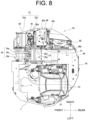
- FIGS. 8 and 9 the placement configuration of the controller 51 according to a third embodiment is to be described. Further, in the partially enlarged view in FIG. 9 , illustrating of the upper side of the plate member 18a in the bulkhead 18 is omitted for convenience of explanation.
- the third embodiment shares with the second embodiment in that the controller 51 is placed in the gap between the hydraulic oil tank 48 and the bulkhead 18, but differs from the second embodiment in that the controller 51 is placed on the left side wall part 48b side of the hydraulic oil tank 48.
- the left side wall part 48b of the hydraulic oil tank 48 is positioned in front of the back face (back side wall part 48c) of the hydraulic oil tank 48, and has a surface which is flat. Further, the left side wall part 48b of the hydraulic oil tank 48 is in the middle position relative to the engine 46 behind the hydraulic oil tank 48.
- the controller 51 is placed on the hydraulic oil tank 48's side face facing the inside of the turn frame 7, thereby allowing easy wiring of the wire harness from the controller 51 to the control valve 45 in front of the hydraulic oil tank 48 and to backward from the hydraulic oil tank 48.
- a mount member (not shown) that serves as a spacer is interposed between the controller 51 and the hydraulic oil tank 48's wall face, thereby to prevent the controller 51 from sticking to the hydraulic oil tank 48. That is, the controller 51 is so placed opposite the hydraulic oil tank 48's wall face as to be spaced apart at a given interval.
- the excavation machine 1 according to the present embodiment equipped with the configuration described above can easily wire the wire harness between the controller 51 and the instrument electrically controlled by the controller 51.
- the excavation machine 1 is provided with the hydraulic system that controls the flow direction and flowrate of the hydraulic oil of the control valve 45 based on the electric signal input from the operation device 47, and the controller 51 is so placed as to oppose the hydraulic oil tank 48.
- the so placing as to oppose includes not only a case in which the controller 51 opposes the hydraulic oil tank 48 by being placed on another member placed around the hydraulic oil tank 48 in an adjacent relation to the hydraulic oil tank 48 (first and second embodiments), but also a case in which the controller 51 is placed in a position at a given interval relative to the hydraulic oil tank 48 by a mount member, including a holder or spacer, that allows the controller 51 to be mounted to the hydraulic oil tank 48 (third embodiment).
- the above configuration can simplify the wiring of the wiring harness to the configuration that is communicably connected to the controller 51.
- the controller 51 in the front-back direction of the turn frame 7, is placed in front of the back side wall part 48c of the hydraulic oil tank 48.
- the above configuration allows for the simplified wiring of the wiring harness between the controller 51 and the control valve 45, for both the front and rear directions of the hydraulic oil tank 48.
- the controller 51 is placed between the hydraulic oil tank 48 and the control valve 45.
- the above configuration allows for the simplified wiring of the wire harness between the controller 51 and the control valve 45, while effectively using the gap between the members of the right engine chamber 9a.
- the controller 51 is supported on the wall part (bulkhead 18) on the driver seat 15 side, the wall part being opposite the hydraulic oil tank 48.
- the controller 51 is placed on the side of the hydraulic oil tank 48. As shown in the plan views in FIGS. 6 and 8 , the hydraulic oil tank 48 is so placed as to be spaced apart from the bulkhead 18 in the right engine chamber 9a, causing a space between the hydraulic oil tank 48's left side wall part 48b and the bulkhead 18. Making effective use of the above space allows the controller 51 to be placed in a position where the wiring harness can be easily wired to the control valve 45.
- controller 51 is supported to the hydraulic oil tank 48.
- the hydraulic oil tank 48 in view of its function of tanking the oil inside, is formed by a sheet metal of a thickness that is not flexed and deformed attributable to the hydraulic pressure of the oil due. That is, it can be said that the hydraulic oil tank 48 is strong enough to make it possible to place the mount member of the controller 51. Using the side face of the hydraulic oil tank 48 as the place for the controller 51 makes it possible to place the controller 51 in the position where the wiring of the wire harness to the control valve 45 is easy.
- the cool mechanism 60 that cools the hydraulic oil is placed behind the hydraulic oil tank 48.
- the above configuration makes it easy to connect the piping between the cool path of the cool water that cools the engine 46 placed behind the turn frame 7 and the cool path of the hydraulic oil to be tanked in the hydraulic oil tank 48.
- the battery 49 is placed in front of the control valve 45, but may be mounted, for example, below the cool mechanism 60 behind the hydraulic oil tank 48. In this case, it is preferable that the battery 49 should be placed in a position not blocking a ventilation opening of the right rear side face cover part 16b.
- the hydraulic pump 41 is mechanically connected to the engine 46, but it may be so made that an electric motor that drives the hydraulic pump 41 is provided separate from the engine 46 and the hydraulic pump 41 is driven by the electric motor. Further, it may be so made that a large-capacity rechargeable battery, separate from the battery 49, is mounted to the turn frame 7, and an electric motor activated by an external power supply and power supply from the rechargeable battery is employed as the prime mover, in place of the engine 46 as the diesel engine.
- the layout on the turn frame 7 has the cabin 10 on the left side and the engine chamber 9 on the right side and rear, but the right and left configurations may be reversed.
- the control valve 45 may be placed on the left side of the turn frame 7, for example, below the cabin 10, relative to the hydraulic oil tank 48 placed on the right side of the turn frame 7. Further, the posture for placing the control valve 45 is properly selected, such as vertical or horizontal, depending on the space.
- the present invention may take the following modes.
Landscapes
- Engineering & Computer Science (AREA)
- Mining & Mineral Resources (AREA)
- Civil Engineering (AREA)
- General Engineering & Computer Science (AREA)
- Structural Engineering (AREA)
- Mechanical Engineering (AREA)
- Operation Control Of Excavators (AREA)
- Component Parts Of Construction Machinery (AREA)
Abstract
Description
- The present invention relates to a construction machine that electrically controls a control valve that controls, for example, the direction and flowrate of a hydraulic oil supplied to a hydraulic actuator.
- Conventionally, a construction machine such as an excavation machine, for example, is provided with devices such as an engine, a work device, a run device, etc., and, so as to electrically control the action of these devices, is further provided with a controller that corresponds to each of these devices. To a power unit such as a control valve, the controller sends an output signal which corresponds to an input signal from an operation part, thereby to causes each device to act. The above controller is provided with an electronic instrument such as a processor that performs an arithmetic process. Due to this, the controller is placed in a place which is not affected by heat and which is protected from a vibration and a shock (see, for example, Patent Document 1).
-
Patent Document 1 discloses a configuration in which the controller is placed on a rear face of a transverse plate that reinforces a support bracket that supports, in a turn frame, a base end part of a front work machine. - Patent document 1:
Japanese Unexamined Patent Application Publication No. 2009-068172 - An electric part, such as the controller, installed on the construction machine is interconnected with a mechanical part, which serves as a power unit, by means of a wire harness as a supply line for electric power and a communication line for a signal. Further, in the construction machine provided with plural hydraulic instruments activated by a hydraulic pressure, a solenoid control valve is employed for the control valve that adjusts the flow direction and flowrate of the hydraulic oil, and the action of the control valves is electrically controlled by the controller. In the above electrically controlled construction machine where the action of the hydraulic instrument is controlled by electricity, the wire harness, as the case may be, is difficult to wire in relation to the layout of each machine part in the turn frame. For example, the area around the position where the controller is placed in the placement configuration disclosed in
Patent Document 1 is a space in capable of placing the control valve. This causes the control valve to be placed in a position far from the controller, causing a problem of increasing the difficulty of wiring the wire harness. - Further, the controller that outputs the electric signal to the control valve needs to receive a pressure signal of a hydraulic pump that discharges a hydraulic oil toward the control valve. Thus, the controller sends and receives signal to and from plural instruments; thus, in view of the positional relation of each instrument, plural wire harnesses must be wired from one controller. Thus, it is desirable for the controller to be placed in a position where it is easy to wire the wire harnesses from plural instruments.
- The present invention has been made in view of the above problem; it is an object of the present invention to provide a construction machine capable of easily wiring a wire harness between a controller and a control valve.
- A construction machine according to the present invention includes, on a vehicle body frame: a hydraulic oil tank that tanks a hydraulic oil discharged by a hydraulic pump driven by a prime mover; a control valve that controls a flow direction and flowrate of the hydraulic oil to a plurality of hydraulic actuators actuated by the hydraulic oil discharged from the hydraulic pump; and a controller that controls the control valve, wherein the control valve is placed is a position opposing the hydraulic oil tank.
- The construction machine according to another mode of the present invention, wherein the controller is placed in front of a back face part of the hydraulic oil tank.
- The construction machine according another mode of the present invention, wherein the hydraulic oil tank is placed on one of right and left sides of the vehicle body frame, and the controller is placed inside the hydraulic oil tank's side face facing an outside of the vehicle body frame.
- The construction machine according to another mode of the present invention, wherein the control valve is placed in front of the hydraulic oil tank, and the controller is placed between the control valve and the hydraulic oil tank.
- The construction machine according to another mode of the present invention, wherein the controller is placed on a side of the hydraulic oil tank.
- The construction machine according to another mode of the present invention, wherein the controller is supported to the hydraulic oil tank.
- The construction machine according to another mode of the present invention, wherein a partition plate to partition the hydraulic oil tank and the control valve is provided on the vehicle body frame, and the controller is supported to the partition plate.
- The construction machine according to another mode of the present invention, wherein a driver seat is placed on another of the right and left sides of the vehicle body frame, and the controller is supported on a wall part on the driver seat side, the wall part being opposite the hydraulic oil tank.
- The present invention makes it possible to simplify, in an electrically controlled construction machine, a wiring of a wire harness between a controller and a control valve.
-
-
FIG. 1 is a right side view of an excavation machine according to an embodiment of the present invention. -
FIG. 2 is a block diagram describing a hydraulic system of the excavation machine according to the embodiment of the present invention. -
FIG. 3 is a perspective view from the right front, showing a layout of each configuration on a turn frame according to the embodiment of the present invention. -
FIG. 4 is a plan view showing a placement of a controller according to a first embodiment of the present invention. -
FIG. 5 is an enlarged partial perspective view of an area near the controller according to the first embodiment of the present invention. -
FIG. 6 is a plan view showing the placement of the controller according to a second embodiment of the present invention. -
FIG. 7 is an enlarged partial perspective view of the area near the controller according to the second embodiment of the present invention. -
FIG. 8 is a plan view showing the placement of the controller according to a third embodiment of the present invention. -
FIG. 9 is an enlarged partial perspective view of the area near the controller according to the third embodiment of the present invention. - In a construction machine that, by means of an electric signal, controls an action of a control valve that adjusts the flow direction and flowrate of a hydraulic oil pumped toward each of plural hydraulic actuators, for example, the present invention devises a placement of a controller thereby to facilitate a wiring of a wire harness between the controller and an instrument connected to the controller. Descriptions will hereinafter be made on embodiments of the present invention with reference to drawings.
- In the embodiment of the present invention, the description will be made on an excavation machine (shovel), which is a turn work vehicle, as an example of a construction machine according to the present invention. However, the construction machine according to the present invention is not limited to the excavation machine, and is widely applicable to other types of construction machines such as a bulldozer, a crane work machine, a compact truck loader, a skid steer loader, and a wheel loader.
- A description will be made, with reference to
FIG. 1 , on an overall configuration of anexcavation machine 1 according to the present embodiment. Unless a directional view is specified, the terms "front side", "rear side", "right and left side", "plan side" or "up side", "bottom side" or "down side" are used below with reference to a position of an operator seated on a driver seat of theexcavation machine 1. As shown inFIG. 1 , theexcavation machine 1 is a so-called super-mini excavation machine, and includes a self-propelledrun vehicle body 2, and anexcavation device 3 and asoil removal device 4 each of which is a work part mounted to therun vehicle body 2. - The
excavation machine 1 has a pair of right and left crawlertype run parts truck frame 6 as a base supporting the right andleft run parts 5, and aturn frame 7 provided on thetruck frame 6. - The
run part 5 has a configuration in which a crawler is wound around plural rotary bodies such as sprockets supported to a given frame part included in thetruck frame 6. A rear end part of therun part 5 has a drive sprocket 5a as a rotary body. Thetruck frame 6 has acenter frame unit 6a positioned between the right andleft run parts side frame unit 6b provided on each of both right and left sides of thecenter frame unit 6a. - The right and
left run parts hydraulic motors hydraulic motor 44 is a hydraulic actuator that is driven by a supply of a hydraulic oil. In each of therun parts 5, the runhydraulic motor 44 is so provided as to be mounted to a given site such as theside frame unit 6b of thetruck frame 6, and drives the drive sprocket 5a for rotation. Each of the right and left runhydraulic motors respective run parts 5, thereby to cause theexcavation machine 1 to run straightly back and forth or to turn to the right and left. - A
soil removal device 4 is mounted to a front side of thetruck frame 6. Thesoil removal device 4 has a pair ofsupport frames 4a extending in the front-back direction between the right andleft run parts blade 4b as a soil removal plate provided on the tip side of thesupport frame 4a. Thesoil removal device 4 is so provided as to be upped and downed in a rotary manner by a blade cylinder provided between thesupport frame 4a and thetruck frame 6. - The
turn frame 7 is configured in a substantially circular shape in plan view, and is so provided as to turn, relative to thetruck frame 6, in any of right and left directions around an up-down axis. On the upper side of thetruck frame 6, there is provided a turn device including a turn bearing 6c and a turn hydraulic motor (not shown). The turn hydraulic motor is a hydraulic actuator driven by a supply of the hydraulic oil, and turns theturn frame 7 via the turn bearing 6c. - On the
turn frame 7, there is provided adrive part 11. Thedrive part 11 is for driving and operating therun vehicle body 2, theexcavation device 3, and thesoil removal device 4, and is provided in acabin 10 provided on theturn frame 7. Thecabin 10 has a frame that forms an outline thereof and a plurality of window parts made of a transparent member such as glass, and is configured as a whole in a substantially box shape. A door is provided on the left side of thecabin 10, serving as an entrance/exit for an operator to and from thedrive part 11. - In the
drive part 11; a driverseat support base 14 as a seat mount is provided on a rear side of a floor part, and adriver seat 15 is provided on the driver seat support base 14 (seeFIG. 3 ). Thedrive part 11 is provided with, for example, a pair of run levers extending upward from the floor part and a work operation pedal provided on the floor part. Further, in thedrive part 11, thedriver seat 15 is surrounded by a work operation lever for operating the work part (excavation device 3 or soil removal device 4) and an operation panel part having various operation parts such as a switch. The work operation lever, which is included in the work part, is also referred to as an electric joystick, and outputs an electric signal that is in response to the operation amount of the operator. - Further, on the
turn frame 7, there is provided an engine chamber 9 that covers an engine and the like covered with a hood. Th engine chamber 9 includes aright engine chamber 9a positioned on the right side of theturn frame 7 and arear engine chamber 9b positioned in a rear part of theturn frame 7. - A
counterweight 7a is provided in a rear down part of theturn frame 7. Further, theturn frame 7 includes aright hood 16 and arear hood 17 as exterior covers. - The
right hood 16 has a right front sideface cover part 16a, a right rear sideface cover part 16b, and an upperface cover part 16c, covering theright engine chamber 9a on the right side of theturn frame 7. The right rear sideface cover part 16b is formed with a vent for ventilation in and out of the engine chamber 9. The right front sideface cover part 16a, the right rear sideface cover part 16b, and the upperface cover part 16c are connected via a connection member. The left side of the upperface cover part 16c is rotatably supported by a hinge part, so that the right front sideface cover part 16a, the right rear sideface cover part 16b, and the upperface cover part 16c can be integrally opened and closed in the up-down direction. Further, theright hood 16 may be so configured that the right front sideface cover part 16a, the right rear sideface cover part 16b, and the upperface cover part 16c can be individually opened or removed. Further, on the left side of theright engine chamber 9a, there is provided abulkhead 18, and an area between thebulkhead 18 and thecabin 10 is a transfer area for aboom 21, described below, of theexcavation device 3. - The
rear hood 17 is provided above thecounterweight 7a, and together with thecounterweight 7a, covers therear engine chamber 9b in the rear part of theturn frame 7. Therear hood 17, with its one side on each of right and left rotatably supported by a hinge part, is so provided as to open and close. - The
excavation device 3 is a front work machine that is provided on a front side of theexcavation machine 1. On the front side of theturn frame 7, and between theright engine chamber 9a and thecabin 10, there is provided aboom support part 19 by which a base part of theexcavation device 3 is rotatably supported. - The
boom support part 19 includes apivot shaft 19a, which is bridged between thebulkhead 18 on theright engine chamber 9a side and awall part 13 on thecabin 10 side and by which the base part of theboom 21 to be described below is pivotally supported, and acylinder bracket 19b by which a cylinder side end part of aboom cylinder 26 to be described below is rotatably supported (seeFIG. 4 ). Thecylinder bracket 19b has such a configuration that asupport shaft 19c parallel to thepivot shaft 19a is bridged to a pair of support plates so provided on theturn frame 7 as to protrude upward. Further, thebulkhead 18 on theright engine chamber 9a side includes aplate member 18a, which has the same height as ahydraulic oil tank 48 and constitutes the left side face of theright engine chamber 9a, and arib part 18b (seeFIG. 6 ) which extends in the front-back direction with the left-right direction as the plate thickness direction and which is also a reinforcing member of theturn frame 7. Further, thewall part 13 on thecabin 10 side, like therib part 18b, extends in the front-back direction with the left-right direction as the plate thickness direction and which is also a reinforcing member of theturn frame 7. - The
excavation device 3 has theboom 21 that is included in a base part side of theexcavation device 3, anarm 22 that is connected to a tip side of theboom 21, and abucket 23 that is mounted to a tip part of thearm 22. Further, theboom 21 includes afirst boom 21a, asecond boom 21b, and athird boom 21c. - The
first boom 21a has a configuration where a tip side is bent forward at an obtuse angle in side view, and a base end is supported by theboom support part 19 provided on the turn frame 7 (seeFIG. 3 ). The base end of thefirst boom 21a is pivotally supported on thepivot shaft 19a (seeFIG. 4 ) which has a left-right axial direction, thereby to so support theboom 21 on theturn frame 7 as to swing in an up-down direction. - A base end of the
second boom 21b is so supported to the tip of thefirst boom 21a as to swing in the left-right direction. - The
third boom 21c has a substantially triangular shape in side view, and is so supported to the tip of thesecond boom 21b as to swing in the left-right direction. Thefirst boom 21a and thethird boom 21c are connected to each other by an offsetlink 24 provided parallel to thesecond boom 21b. Thefirst boom 21a, thesecond boom 21b, thethird boom 21c and the offsetlink 24 are so connected as to form a parallelogram link mechanism. - The
excavation device 3 has aboom cylinder 26 to rotate thefirst boom 21a, an offsetcylinder 27 to rotate thesecond boom 21b and the offsetlink 24, anarm cylinder 28 to rotate thearm 22, and awork tool cylinder 29 to rotate thebucket 23. The above cylinders are each a hydraulic cylinder. In theexcavation device 3, another device such as a grapple or a breaker is mounted instead of thebucket 23 in accordance with work contents. - On the front side of the
first boom 21a, theboom cylinder 26 is provided along the length direction of thefirst boom 21a. The base end (cylinder side end part) of theboom cylinder 26 is rotatably supported on thesupport shaft 19c of thecylinder bracket 19b (seeFIG. 3 ). As theboom cylinder 26 extends and retracts, thefirst boom 21a swings around thepivot shaft 19a. - On the left side face of the
second boom 21b, the offsetcylinder 27 is placed in the length direction. The rod side end part of the offsetcylinder 27 is rotatably connected to the left side face part of thethird boom 21c via a bracket. The cylinder side end part of the offsetcylinder 27 is rotatably connected to a bracket protruding from the left side face part on the base end side of thesecond boom 21b. The offsetcylinder 27 extends and retracts, thereby to swing thesecond boom 21b and the offsetlink 24 to the right and left. - The
arm cylinder 28 has its cylinder side rotatably supported by thethird boom 21c and its rod side end part rotatably supported by abracket part 37 provided on the base end side of thearm 22. Thearm 22, by the extending and retracting of thearm cylinder 28, swings around a connection shaft between thearm 22 and thethird boom 21c with the left-right direction as an axial direction. - The
work tool cylinder 29 is provided along the length direction of thearm 22, has the cylinder side rotatably supported by thebracket part 37 provided on the base end side of thearm 22, and has the rod side end part rotatably supported by abracket part 38 on thebucket 23 side. Thebucket 23, by the extending and retracting of thework tool cylinder 29, swings around a connection shaft between thebucket 23 and thearm 22 with the left-right direction as an axial direction. - In the
excavation machine 1 provided with the above configuration, the operator who is seated on thedriver seat 15 properly operates the run lever, the work operation lever and the like, thereby to perform a desired action or work. Specifically, operating the run lever, for example, causes theexcavation machine 1 to make a front-back linear run or a right/left turn run. Further, operating the work operation lever causes theexcavation device 3 to perform the excavating work, or causes thesoil removal device 4 to perform the soil removal work or leveling work. - The
excavation machine 1 according to the present embodiment is a construction machine that, by electric control, controls the action of a plurality of hydraulic actuators.FIG. 2 shows a block diagram of part of an electric control hydraulic system of theexcavation machine 1. InFIG. 2 , anactuator 43 refers to any one of various hydraulic actuators, such as a blade cylinder, theboom cylinder 26, the offsetcylinder 27, thearm cylinder 28, thework tool cylinder 29, the runhydraulic motor 44, and the turn hydraulic motor. - The
engine 46 is configured as a diesel engine, for example, and is placed in therear engine chamber 9b that is in a transverse direction with the drive shaft's axial direction in substantially left-right direction and that is positioned in the rear part of theturn frame 7.Th engine 46 is a drive source for a hydraulic pump 41 (main pump) and apilot pump 42, and thehydraulic pump 41 and thepilot pump 42 are mechanically connected to theengine 46. - The
hydraulic pump 41 is for supplying the hydraulic oil in thehydraulic oil tank 48 to theactuator 43 via adirection switch valve 45a of acontrol valve 45 to be described below. Thehydraulic pump 41 and thedirection switch valve 45a are connected by asupply piping 61. Thesupply piping 61 is provided with apressure sensor 63 for detecting a discharge pressure of the hydraulic oil discharged from thehydraulic pump 41. A detection signal of thepressure sensor 63 is input via a communication line to acontroller 51. - The
pilot pump 42 is for supplying a pilot pressure to thedirection switch valve 45a via a solenoidproportional valve 45b of thecontrol valve 45. Thepilot pump 42 and the solenoidproportional valve 45b are connected by a pilotpressure supply piping 62. - The
control valve 45 is so configured as to control the flow direction and flowrate of the hydraulic oil in the hydraulic system. In the present embodiment; to one or more of the blade cylinder, theboom cylinder 26, the offsetcylinder 27, thearm cylinder 28, thework tool cylinder 29, the right and left runhydraulic motors 44, and the turn hydraulic motor, thecontrol valve 45 selectively supplies the hydraulic oil discharged from thehydraulic pump 41. Thus, in the actual hydraulic system, thecontrol valve 45 is configured as a valve unit including adirection switch valve 45a and a solenoidproportional valve 45b for each of theplural actuators 43. - The
direction switch valve 45a is a pilot-operated direction control valve, and includes, for example, a 4-port, 3-position hydraulic pilot operated direction control valve. Thedirection switch valve 45a is provided with a plurality of ports to which hydraulic pipings including tubes, etc., are connected. Connected to each port include asupply piping 61 as a discharge line of thehydraulic pump 41, a supply-discharge piping 65 as a hydraulic pressure supply line to theactuator 43 and a hydraulic pressure discharge line from theactuator 43, and a return piping 66 as a return line to thehydraulic oil tank 48. - A current corresponding to the operation amount of an
operation device 47 is output from thecontroller 51 to the solenoidproportional valve 45b; then, to an input port of thedirection switch valve 45a, the solenoidproportional valve 45b outputs a pilot pressure proportional to the input current, thereby to slide a souple of the direction switch valve. - The
operation device 47 refers to various operation devices, such as a run lever, a work operation pedal, and a work operation lever, which are provided on thedrive part 11, and which correspond to therespective actuators 43. - The action of the
control valve 45 is controlled by thecontroller 51. Thecontroller 51, also referred to as an ECU (Electronic Control Unit), includes a computer unit, which includes an arithmetic unit and a storage, and a communication module. From the No. 1operation device 47 that corresponds to the No. 1actuator 43, thecontroller 51 receives an electric signal that is in response to the operator's operation, and outputs, to the solenoidproportional valve 45b, an instruction signal which is based on the electric signal. This adjusts the pilot pressure given from the solenoidproportional valve 45b to thedirection switch valve 45a, thereby to control the direction flow and flowrate of the hydraulic oil by thedirection switch valve 45a. - In the hydraulic system provided with the above configuration, controlling the hydraulic oil supplied via the
control valve 45 to theactuator 43 activates theexcavation device 3 and turns theturn frame 7. - Referring to
FIG. 3 , the layout of the various configurations on theturn frame 7 is further described, especially the configuration placed in theright engine chamber 9a. Further,FIG. 3 shows a state of removing thecabin 10 and the exterior covers (right hood 16 and rear hood 17). - The
right engine chamber 9a is a housing chamber that, on one side (right side) of a machine body, houses thehydraulic oil tank 48, thecontrol valve 45, abattery 49, and acool mechanism 60. Further, thedriver seat 15 is placed on the other side (left side) of the machine body. - The
hydraulic oil tank 48 has a substantially prismatic column shape having a rightside wall part 48a, a leftside wall part 48b, a backside wall part 48c, and a frontside wall part 48d (seeFIG. 4 ). Thehydraulic oil tank 48, due to the hydraulic oil tanked therein thereby to make its weight heavier than other configurations such as thecontrol valve 45 and thebattery 49, in view of a weight balance on theturn frame 7, is placed in a position in the center of theright engine chamber 9a in the front-back direction. Thehydraulic oil tank 48, by being placed in theright engine chamber 9a, is placed on one side (right side) on right and left of theturn frame 7. - The
cool mechanism 60 includes a radiator for cooling the cool water of theengine 46, an oil cooler for cooling the hydraulic oil, and a cool fan. In the present embodiment, theengine 46 is placed in the rear part of theturn frame 7, so thecool mechanism 60 is placed in a position that is behind thehydraulic oil tank 48 and that is close to theengine 46. - The
control valve 45 is placed in front of thehydraulic oil tank 48. Thecontrol valve 45 is supported vertically on thesupport member 52. Thesupport member 52 includes abottom plate part 52a, and aback plate part 52b erected on thebottom plate part 52a. Thebottom plate part 52a and theback plate part 52b are formed by bending a sheet metal into substantially an L-shape in side view, and theback plate part 52b covers the back side of thecontrol valve 45. - The
control valve 45, in plan view (seeFIG. 4 ), is so placed toward thebulkhead 18 as to be offset from a side face (leftside wall part 48b) opposite thehydraulic oil tank 48's side face (rightside wall part 48a) facing the right front sideface cover part 16a. That is, thecontrol valve 45 is placed in a position more shifted inside theturn frame 7 so that, in the right-left width direction of thehydraulic oil tank 48, an entirety of thecontrol valve 45 is housed within a substantially circular outline of theturn frame 7 and the supply-discharge piping 65 can be easily connected to thedirection switch valve 45a. - The
battery 49 is placed in front of thecontrol valve 45. More specifically, thebattery 49 is fixed to the front part of thebottom plate part 52a of thesupport member 52. - As described above, in the
right engine chamber 9a, which is covered with theright hood 16 on the right side as one of the right and left sides of theturn frame 7, thehydraulic oil tank 48 is placed in the center of theright engine chamber 9a in the front-back direction. Then, in theright engine chamber 9a, it is so configured that thecontrol valve 45 is placed in front of thehydraulic oil tank 48, thebattery 49 is further placed in front of thecontrol valve 45, and thecool mechanism 60 is placed behind thehydraulic oil tank 48. - Further, the above placing of the
hydraulic oil tank 48, thecontrol valve 45, and thebattery 49 secures, in front of thecontrol valve 45 and above thebattery 49, a space for easily connecting the hydraulic pipings (supply piping 61, supply-discharge piping 65, return piping 66) to the respective direction switchvalves 45a. The above placing does not cause a physical interfere with the multiple hydraulic pipings connected to thecontrol valve 45, and does not cause an obstacle to maintenance work on thebattery 49. - Next, the placement of the
controller 51 is to be further described. - The
controller 51 provides a control signal (current of a given magnitude) via the wire harness to the solenoidproportional valve 45b of thecontrol valve 45, and has a substantially cuboid shape with a thin thickness. That is, the outline of a casing that forms the exterior of thecontroller 51 is a substantially rectangular plate shape. Thecontroller 51 and thecontrol valve 45 are electrically connected by a wire harness (not shown) as a power supply line and a signal communication line. - It is preferable that the
controller 51 should be fixed to a flat face in a manner to prevent thecontroller 51 itself from moving even when, for example, a tensile load is applied to the connected wire harness. Thus, from the viewpoint of securing a mount face of thecontroller 51, thecontroller 51 is adjacently placed in a manner to oppose the box-shapedhydraulic oil tank 48 having a flat face on its outer peripheral wall. - Further, the
controller 51 is an electronic instrument, and is required to be placed in a position not susceptible to an external shock. In theright engine chamber 9a, thecontroller 51 is mounted in a position that is inside thehydraulic oil tank 48's side face (rightside wall part 48a) that faces the right front sideface cover part 16a of theright hood 16, that is, in a position which is, in the area around the adjacenthydraulic oil tank 48, well spaced apart from the exterior cover. This can prevent a direct shock on thecontroller 51, even when, for example, a transverse shock is applied to theright hood 16. - Further, the
controller 51, as the case may be, communicates with another instrument via the wire harness, such as acquiring, from thepressure sensor 63, the pressure value of the hydraulic oil discharged from thehydraulic pump 41 when generating the control signal. Due to this, for wiring the wire harness to thecontroller 51, the wiring path is provided along a member included in a frame structure that is away from the exterior cover, that is inside the machine body, and that is of theturn frame 7. This can prevent the wire harness from being damaged by an external force. - The specific placement of the
controller 51 is to be described below with reference toFIGS. 4 to 9 . - Referring to
FIGS. 4 and5 , the placement configuration of thecontroller 51 according to the first embodiment is to be described. - In the first embodiment, the
controller 51 is placed between thecontrol valve 45 and thehydraulic oil tank 48, as shown in the plan view inFIG. 4 . Specifically, thecontroller 51 is mounted on theback plate part 52b of thesupport member 52 that supports the control valve 45 (seeFIG. 5 ). Fastening thecontroller 51 to the rear-facing back face part of theback plate part 52b by screw fastening or the like places thecontroller 51 between thecontrol valve 45 and thehydraulic oil tank 48. - In the first embodiment, as shown in
FIG. 5 , thecontroller 51 is so placed on theback plate part 52b near thecontrol valve 45 as to be back-to-back with thecontrol valve 45. Theback plate part 52b of thesupport member 52 is a partition plate that partitions, on theturn frame 7, the placement area of thecontrol valve 45 on the front side and the placement area of thehydraulic oil tank 48 on the rear side, and that is placed between thehydraulic oil tank 48 and thecontrol valve 45. In the present embodiment, thecontroller 51 is placed on the partition plate, thereby making it possible to reduce the distance between thecontrol valve 45 and thecontroller 51, making it possible to simplify the wiring of the wiring harness. Further, providing, in theback plate part 52b of thesupport member 52, a hole part through which the wire harness can be inserted makes it is possible to shorten the wiring path of the wire harness. - Further, in the first embodiment, the
controller 51 is mounted on theback plate part 52b of thesupport member 52 of thecontrol valve 45 placed in front of thehydraulic oil tank 48; but thecontroller 51, via a holder or other mount member holding thecontroller 51, may be mounted on thehydraulic oil tank 48's frontside wall part 48d facing theback plate part 52b. - Referring to
FIGS. 6 and7 , the placement configuration of thecontroller 51 according to a second embodiment is to be described. - In the second embodiment, the
controller 51 is placed in a gap between thehydraulic oil tank 48 and thebulkhead 18, as shown in the plan view inFIG. 6 . Specifically, thecontroller 51 is fixed to theplate member 18a in thebulkhead 18 by screw fastening or the like (seeFIG. 7 ). Here, thehydraulic oil tank 48 is placed in the center position of theright engine chamber 9a in the front-back direction, and thecontroller 51 is mounted on thebulkhead 18 adjacent to the left side of thehydraulic oil tank 48. That is, thecontroller 51 is placed in the middle position between thecontrol valve 45 in front of thehydraulic oil tank 48 and theengine 46 behind thehydraulic oil tank 48. Thus, in the present embodiment, thecontroller 51 is extended in the front-back direction in plan view with the plate thickness direction as the left-right direction, so that, on theturn frame 7, thecontroller 51 faces the outside face of theturn frame 7. Then, thecontroller 51 is supported by thebulkhead 18 as the bulkhead part that defines the area housing thehydraulic oil tank 48 and thecontrol valve 45. This can simplify the wiring of the wiring harness to both thecontrol valve 45 side and the engine 46 (pressure sensor 63) side. - Further, the
bulkhead 18 includes not only theplate member 18a, which covers the area up to the height of one side end of the upperface cover part 16c of theright hood 16, but also therib part 18b, which is a reinforcing member of theturn frame 7. That is, thecontroller 51 may be mounted on therib part 18b. On the left side of theright engine chamber 9a, thecontroller 51, at different heights or in different front/rear positions, can be placed to a member that functions as a bulkhead separating theright engine chamber 9a from the movement area of theboom 21. - Referring to
FIGS. 8 and9 , the placement configuration of thecontroller 51 according to a third embodiment is to be described. Further, in the partially enlarged view inFIG. 9 , illustrating of the upper side of theplate member 18a in thebulkhead 18 is omitted for convenience of explanation. - In plan view, the third embodiment shares with the second embodiment in that the
controller 51 is placed in the gap between thehydraulic oil tank 48 and thebulkhead 18, but differs from the second embodiment in that thecontroller 51 is placed on the leftside wall part 48b side of thehydraulic oil tank 48. - The left
side wall part 48b of thehydraulic oil tank 48 is positioned in front of the back face (backside wall part 48c) of thehydraulic oil tank 48, and has a surface which is flat. Further, the leftside wall part 48b of thehydraulic oil tank 48 is in the middle position relative to theengine 46 behind thehydraulic oil tank 48. In the third embodiment, thecontroller 51 is placed on thehydraulic oil tank 48's side face facing the inside of theturn frame 7, thereby allowing easy wiring of the wire harness from thecontroller 51 to thecontrol valve 45 in front of thehydraulic oil tank 48 and to backward from thehydraulic oil tank 48. - Further, for placing the
controller 51 on thehydraulic oil tank 48's wall face, a mount member (not shown) that serves as a spacer is interposed between thecontroller 51 and thehydraulic oil tank 48's wall face, thereby to prevent thecontroller 51 from sticking to thehydraulic oil tank 48. That is, thecontroller 51 is so placed opposite thehydraulic oil tank 48's wall face as to be spaced apart at a given interval. - The
excavation machine 1 according to the present embodiment equipped with the configuration described above can easily wire the wire harness between thecontroller 51 and the instrument electrically controlled by thecontroller 51. - In the first to third embodiments, the
excavation machine 1 is provided with the hydraulic system that controls the flow direction and flowrate of the hydraulic oil of thecontrol valve 45 based on the electric signal input from theoperation device 47, and thecontroller 51 is so placed as to oppose thehydraulic oil tank 48. The so placing as to oppose here includes not only a case in which thecontroller 51 opposes thehydraulic oil tank 48 by being placed on another member placed around thehydraulic oil tank 48 in an adjacent relation to the hydraulic oil tank 48 (first and second embodiments), but also a case in which thecontroller 51 is placed in a position at a given interval relative to thehydraulic oil tank 48 by a mount member, including a holder or spacer, that allows thecontroller 51 to be mounted to the hydraulic oil tank 48 (third embodiment). The above configuration can simplify the wiring of the wiring harness to the configuration that is communicably connected to thecontroller 51. - Further, in the first to third embodiments, the
controller 51, in the front-back direction of theturn frame 7, is placed in front of the backside wall part 48c of thehydraulic oil tank 48. The above configuration allows for the simplified wiring of the wiring harness between thecontroller 51 and thecontrol valve 45, for both the front and rear directions of thehydraulic oil tank 48. - Further, in the first embodiment, the
controller 51 is placed between thehydraulic oil tank 48 and thecontrol valve 45. The above configuration allows for the simplified wiring of the wire harness between thecontroller 51 and thecontrol valve 45, while effectively using the gap between the members of theright engine chamber 9a. - Further, in the second embodiment; in the configuration where the
right engine chamber 9a is provided on the right side as one of the right and left sides of the vehicle frame (turn frame 7), and thedriver seat 15 is placed on the left side as the other side, thecontroller 51 is supported on the wall part (bulkhead 18) on thedriver seat 15 side, the wall part being opposite thehydraulic oil tank 48. The above configuration allows for the simplified wiring of the wire harness between thecontroller 51 and thecontrol valve 45, while effectively using the gap between the members of theright engine chamber 9a. - Further, in the second and third embodiments, the
controller 51 is placed on the side of thehydraulic oil tank 48. As shown in the plan views inFIGS. 6 and8 , thehydraulic oil tank 48 is so placed as to be spaced apart from thebulkhead 18 in theright engine chamber 9a, causing a space between thehydraulic oil tank 48's leftside wall part 48b and thebulkhead 18. Making effective use of the above space allows thecontroller 51 to be placed in a position where the wiring harness can be easily wired to thecontrol valve 45. - Further, in the third embodiment, the
controller 51 is supported to thehydraulic oil tank 48. - The
hydraulic oil tank 48, in view of its function of tanking the oil inside, is formed by a sheet metal of a thickness that is not flexed and deformed attributable to the hydraulic pressure of the oil due. That is, it can be said that thehydraulic oil tank 48 is strong enough to make it possible to place the mount member of thecontroller 51. Using the side face of thehydraulic oil tank 48 as the place for thecontroller 51 makes it possible to place thecontroller 51 in the position where the wiring of the wire harness to thecontrol valve 45 is easy. - Further, in the first to third embodiments, the
cool mechanism 60 that cools the hydraulic oil is placed behind thehydraulic oil tank 48. The above configuration makes it easy to connect the piping between the cool path of the cool water that cools theengine 46 placed behind theturn frame 7 and the cool path of the hydraulic oil to be tanked in thehydraulic oil tank 48. - The above description of the embodiment is merely one example of the present invention, and the construction machine according to the present invention is not limited to the above embodiment. Due to this, it is needless to say that, even to those other than the above embodiment, various changes can be made according to the design and the like within the scope that does not depart from the technical concept of the present invention. Further, the effects described in the present disclosure are merely exemplary and are not limited, and another effect may also be exerted.
- In the above embodiment, the
battery 49 is placed in front of thecontrol valve 45, but may be mounted, for example, below thecool mechanism 60 behind thehydraulic oil tank 48. In this case, it is preferable that thebattery 49 should be placed in a position not blocking a ventilation opening of the right rear sideface cover part 16b. - Further, in the above embodiment, the
hydraulic pump 41 is mechanically connected to theengine 46, but it may be so made that an electric motor that drives thehydraulic pump 41 is provided separate from theengine 46 and thehydraulic pump 41 is driven by the electric motor. Further, it may be so made that a large-capacity rechargeable battery, separate from thebattery 49, is mounted to theturn frame 7, and an electric motor activated by an external power supply and power supply from the rechargeable battery is employed as the prime mover, in place of theengine 46 as the diesel engine. - Further, in the above embodiment, the layout on the
turn frame 7 has thecabin 10 on the left side and the engine chamber 9 on the right side and rear, but the right and left configurations may be reversed. Further, as long as being positioned in front of thehydraulic oil tank 48 in the front-back direction on theturn frame 7, thecontrol valve 45 may be placed on the left side of theturn frame 7, for example, below thecabin 10, relative to thehydraulic oil tank 48 placed on the right side of theturn frame 7. Further, the posture for placing thecontrol valve 45 is properly selected, such as vertical or horizontal, depending on the space. - The present invention may take the following modes.
- (1) A construction machine, on a vehicle body frame, comprising:
- a hydraulic oil tank that tanks a hydraulic oil discharged by a hydraulic pump driven by a prime mover;
- a plurality of hydraulic actuators actuated by the hydraulic oil discharged from the hydraulic pump;
- a control valve that controls a flow direction and flowrate of the hydraulic oil to a plurality of hydraulic actuators; and
- a controller that controls the control valve,
the control valve is placed is a position opposing the hydraulic oil tank. - (2) The construction machine according to (1), wherein
the controller is placed in front of a back face part of the hydraulic oil tank. - (3) The construction machine according to (1) or (2), wherein
- the hydraulic oil tank is placed on one of right and left sides of the vehicle body frame, and
- the controller is placed inside the hydraulic oil tank's side face facing an outside of the vehicle body frame.
- (4) The construction machine according to any of (1) to (3), wherein
- the control valve is placed in front of the hydraulic oil tank, and
- the controller is placed between the control valve and the hydraulic oil tank.
- (5) The construction machine according to any of (1) to (3), wherein
the controller is placed on a side of the hydraulic oil tank. - (6) The construction machine according to any of (1) to (5), wherein
the controller is supported to the hydraulic oil tank. - (7) The construction machine according to any of (1) to (4), wherein
- a partition plate to partition the hydraulic oil tank and the control valve is provided on the vehicle body frame, and
- the controller is supported to the partition plate.
- (8) The construction machine according to (3) or (5), wherein
- a driver seat is placed on another of the right and left sides of the vehicle body frame, and
- the controller is supported on a wall part on the driver seat side, the wall part being opposite the hydraulic oil tank.
-
- 1 excavation machine (construction machine)
- 2 run vehicle body
- 3 excavation device
- 5 run part
- 7 turn frame (vehicle body frame)
- 11 engine chamber
- 9a right engine chamber
- 10 cabin
- 7 drive part
- 14 driver seat support base
- 15 driver seat
- 16 right hood (exterior cover)
- 18 bulkhead (wall part)
- 18a plate member
- 18b rib part
- 21 boom
- 22 arm
- 23 bucket
- 26 boom cylinder (hydraulic actuator)
- 27 offset cylinder (hydraulic actuator)
- 28 arm cylinder (hydraulic actuator)
- 29 work tool cylinder (hydraulic actuator)
- 41 hydraulic pump
- 42 pilot pump
- 43 hydraulic actuator
- 44 run hydraulic motor (hydraulic actuator)
- 45 control valve
- 46 engine (prime mover)
- 47 operation device
- 48 hydraulic oil tank
- 49 battery
- 51 controller
- 52 support member
- 52b back plate part (partition plate)
- 60 cool mechanism
- 61 supply piping
- 66 return piping
Claims (8)
- A construction machine comprising, on a vehicle body frame:a hydraulic oil tank that tanks a hydraulic oil discharged by a hydraulic pump driven by a prime mover;a control valve that controls a flow direction and flowrate of the hydraulic oil to a plurality of hydraulic actuators actuated by the hydraulic oil discharged from the hydraulic pump; anda controller that controls the control valve,wherein
the control valve is placed is a position opposing the hydraulic oil tank. - The construction machine according to claim 1, wherein
the controller is placed in front of a back face part of the hydraulic oil tank. - The construction machine according to claim 2, whereinthe hydraulic oil tank is placed on one of right and left sides of the vehicle body frame, andthe controller is placed inside the hydraulic oil tank's side face facing an outside of the vehicle body frame.
- The construction machine according to claim 3, whereinthe control valve is placed in front of the hydraulic oil tank, andthe controller is placed between the control valve and the hydraulic oil tank.
- The construction machine according to claim 3, wherein
the controller is placed on a side of the hydraulic oil tank. - The construction machine according to any of claims 1 to 5, wherein
the controller is supported to the hydraulic oil tank. - The construction machine according to any of claims 1 to 4, whereina partition plate to partition the hydraulic oil tank and the control valve is provided on the vehicle body frame, andthe controller is supported to the partition plate.
- The construction machine according to claim 3 or claim 5, whereina driver seat is placed on another of the right and left sides of the vehicle body frame, andthe controller is supported on a wall part on the driver seat side, the wall part being opposite the hydraulic oil tank.
Applications Claiming Priority (1)
| Application Number | Priority Date | Filing Date | Title |
|---|---|---|---|
| JP2022113359A JP7848070B2 (en) | 2022-07-14 | 2022-07-14 | Construction machinery |
Publications (2)
| Publication Number | Publication Date |
|---|---|
| EP4306721A1 true EP4306721A1 (en) | 2024-01-17 |
| EP4306721B1 EP4306721B1 (en) | 2026-02-11 |
Family
ID=87003310
Family Applications (1)
| Application Number | Title | Priority Date | Filing Date |
|---|---|---|---|
| EP23181751.1A Active EP4306721B1 (en) | 2022-07-14 | 2023-06-27 | Construction machine |
Country Status (5)
| Country | Link |
|---|---|
| US (2) | US12345016B2 (en) |
| EP (1) | EP4306721B1 (en) |
| JP (1) | JP7848070B2 (en) |
| KR (1) | KR20240009870A (en) |
| CN (1) | CN117403734A (en) |
Cited By (1)
| Publication number | Priority date | Publication date | Assignee | Title |
|---|---|---|---|---|
| CN118422742A (en) * | 2024-05-28 | 2024-08-02 | 柳工常州机械有限公司 | Power side shift device for excavator loader |
Families Citing this family (4)
| Publication number | Priority date | Publication date | Assignee | Title |
|---|---|---|---|---|
| NL2024981B1 (en) * | 2020-02-24 | 2021-10-14 | Hudson I P B V | Electric drive of mobile apparatus |
| JP7710390B2 (en) * | 2022-02-28 | 2025-07-18 | ヤンマーホールディングス株式会社 | Work Machine |
| JP7848070B2 (en) * | 2022-07-14 | 2026-04-20 | ヤンマーホールディングス株式会社 | Construction machinery |
| JP2024011409A (en) * | 2022-07-14 | 2024-01-25 | ヤンマーホールディングス株式会社 | construction machinery |
Citations (5)
| Publication number | Priority date | Publication date | Assignee | Title |
|---|---|---|---|---|
| JP2009068172A (en) | 2007-09-10 | 2009-04-02 | Caterpillar Japan Ltd | Controller arrangement structure of working machine |
| US20140186151A1 (en) * | 2011-11-11 | 2014-07-03 | Hitachi Constuction Machinery Co., Ltd. | Construction machine |
| JP2016188549A (en) * | 2015-03-30 | 2016-11-04 | 株式会社クボタ | Working machine |
| US20190338493A1 (en) * | 2017-07-18 | 2019-11-07 | Kubota Corporation | Working machine |
| JP2022097078A (en) * | 2020-12-18 | 2022-06-30 | ヤンマーホールディングス株式会社 | Construction machine |
Family Cites Families (10)
| Publication number | Priority date | Publication date | Assignee | Title |
|---|---|---|---|---|
| JPH11336122A (en) * | 1998-03-24 | 1999-12-07 | Kubota Corp | Turning work machine |
| JP5918072B2 (en) * | 2012-08-06 | 2016-05-18 | 株式会社クボタ | Working machine |
| DE112015000230B4 (en) * | 2015-12-18 | 2022-06-30 | Komatsu Ltd. | construction machine |
| JP6808587B2 (en) * | 2017-07-18 | 2021-01-06 | 株式会社クボタ | Work machine |
| EP3656932B1 (en) * | 2017-12-27 | 2024-11-27 | Kubota Corporation | Work equipment and method for producing work equipment |
| US11413955B2 (en) * | 2018-06-29 | 2022-08-16 | Kubota Corporation | Working machine |
| JP6884733B2 (en) * | 2018-06-29 | 2021-06-09 | 日立建機株式会社 | Remote-controlled small hydraulic excavator |
| JP7326221B2 (en) * | 2020-05-28 | 2023-08-15 | 株式会社クボタ | work machine |
| JP7495854B2 (en) * | 2020-09-25 | 2024-06-05 | 日立建機株式会社 | controller |
| JP7848070B2 (en) * | 2022-07-14 | 2026-04-20 | ヤンマーホールディングス株式会社 | Construction machinery |
-
2022
- 2022-07-14 JP JP2022113359A patent/JP7848070B2/en active Active
-
2023
- 2023-06-27 EP EP23181751.1A patent/EP4306721B1/en active Active
- 2023-07-03 KR KR1020230085806A patent/KR20240009870A/en active Pending
- 2023-07-06 CN CN202310822578.4A patent/CN117403734A/en active Pending
- 2023-07-13 US US18/221,845 patent/US12345016B2/en active Active
-
2025
- 2025-06-04 US US19/228,583 patent/US20250297452A1/en active Pending
Patent Citations (5)
| Publication number | Priority date | Publication date | Assignee | Title |
|---|---|---|---|---|
| JP2009068172A (en) | 2007-09-10 | 2009-04-02 | Caterpillar Japan Ltd | Controller arrangement structure of working machine |
| US20140186151A1 (en) * | 2011-11-11 | 2014-07-03 | Hitachi Constuction Machinery Co., Ltd. | Construction machine |
| JP2016188549A (en) * | 2015-03-30 | 2016-11-04 | 株式会社クボタ | Working machine |
| US20190338493A1 (en) * | 2017-07-18 | 2019-11-07 | Kubota Corporation | Working machine |
| JP2022097078A (en) * | 2020-12-18 | 2022-06-30 | ヤンマーホールディングス株式会社 | Construction machine |
Cited By (1)
| Publication number | Priority date | Publication date | Assignee | Title |
|---|---|---|---|---|
| CN118422742A (en) * | 2024-05-28 | 2024-08-02 | 柳工常州机械有限公司 | Power side shift device for excavator loader |
Also Published As
| Publication number | Publication date |
|---|---|
| JP7848070B2 (en) | 2026-04-20 |
| US20250297452A1 (en) | 2025-09-25 |
| KR20240009870A (en) | 2024-01-23 |
| US20240018748A1 (en) | 2024-01-18 |
| US12345016B2 (en) | 2025-07-01 |
| EP4306721B1 (en) | 2026-02-11 |
| JP2024011410A (en) | 2024-01-25 |
| CN117403734A (en) | 2024-01-16 |
Similar Documents
| Publication | Publication Date | Title |
|---|---|---|
| EP4306721B1 (en) | Construction machine | |
| EP2778294B1 (en) | Construction equipment | |
| EP2540915B1 (en) | Electrical construction machine | |
| JP5814577B2 (en) | Electric work vehicle and battery holding structure thereof | |
| KR102594409B1 (en) | Electric construction machinery | |
| KR20130113517A (en) | Electric work vehicle and base frame for same | |
| KR101036859B1 (en) | Cab floor structure | |
| US12624523B2 (en) | Construction machine | |
| KR102426643B1 (en) | Working Machine | |
| JP5771749B2 (en) | Construction machinery | |
| JP2024065874A (en) | Work Machine | |
| KR20240035320A (en) | Working machine | |
| JP6847759B2 (en) | Work machine | |
| JP2024095467A (en) | Construction Machinery | |
| JP2024095469A (en) | Construction Machinery | |
| JPH10331192A (en) | Swiveling construction machine |
Legal Events
| Date | Code | Title | Description |
|---|---|---|---|
| PUAI | Public reference made under article 153(3) epc to a published international application that has entered the european phase |
Free format text: ORIGINAL CODE: 0009012 |
|
| STAA | Information on the status of an ep patent application or granted ep patent |
Free format text: STATUS: THE APPLICATION HAS BEEN PUBLISHED |
|
| AK | Designated contracting states |
Kind code of ref document: A1 Designated state(s): AL AT BE BG CH CY CZ DE DK EE ES FI FR GB GR HR HU IE IS IT LI LT LU LV MC ME MK MT NL NO PL PT RO RS SE SI SK SM TR |
|
| STAA | Information on the status of an ep patent application or granted ep patent |
Free format text: STATUS: REQUEST FOR EXAMINATION WAS MADE |
|
| 17P | Request for examination filed |
Effective date: 20240715 |
|
| RBV | Designated contracting states (corrected) |
Designated state(s): AL AT BE BG CH CY CZ DE DK EE ES FI FR GB GR HR HU IE IS IT LI LT LU LV MC ME MK MT NL NO PL PT RO RS SE SI SK SM TR |
|
| GRAP | Despatch of communication of intention to grant a patent |
Free format text: ORIGINAL CODE: EPIDOSNIGR1 |
|
| STAA | Information on the status of an ep patent application or granted ep patent |
Free format text: STATUS: GRANT OF PATENT IS INTENDED |
|
| INTG | Intention to grant announced |
Effective date: 20250905 |
|
| GRAS | Grant fee paid |
Free format text: ORIGINAL CODE: EPIDOSNIGR3 |
|
| GRAA | (expected) grant |
Free format text: ORIGINAL CODE: 0009210 |
|
| STAA | Information on the status of an ep patent application or granted ep patent |
Free format text: STATUS: THE PATENT HAS BEEN GRANTED |
|
| AK | Designated contracting states |
Kind code of ref document: B1 Designated state(s): AL AT BE BG CH CY CZ DE DK EE ES FI FR GB GR HR HU IE IS IT LI LT LU LV MC ME MK MT NL NO PL PT RO RS SE SI SK SM TR |
|
| REG | Reference to a national code |
Ref country code: CH Ref legal event code: F10 Free format text: ST27 STATUS EVENT CODE: U-0-0-F10-F00 (AS PROVIDED BY THE NATIONAL OFFICE) Effective date: 20260211 Ref country code: GB Ref legal event code: FG4D |
|
| REG | Reference to a national code |
Ref country code: DE Ref legal event code: R096 Ref document number: 602023011780 Country of ref document: DE |
|
| REG | Reference to a national code |
Ref country code: IE Ref legal event code: FG4D |
|
| REG | Reference to a national code |
Ref country code: NL Ref legal event code: MP Effective date: 20260211 |
|
| PG25 | Lapsed in a contracting state [announced via postgrant information from national office to epo] |
Ref country code: RS Free format text: LAPSE BECAUSE OF FAILURE TO SUBMIT A TRANSLATION OF THE DESCRIPTION OR TO PAY THE FEE WITHIN THE PRESCRIBED TIME-LIMIT Effective date: 20260511 |
|
| PG25 | Lapsed in a contracting state [announced via postgrant information from national office to epo] |
Ref country code: ES Free format text: LAPSE BECAUSE OF FAILURE TO SUBMIT A TRANSLATION OF THE DESCRIPTION OR TO PAY THE FEE WITHIN THE PRESCRIBED TIME-LIMIT Effective date: 20260211 |
|
| PG25 | Lapsed in a contracting state [announced via postgrant information from national office to epo] |
Ref country code: PL Free format text: LAPSE BECAUSE OF FAILURE TO SUBMIT A TRANSLATION OF THE DESCRIPTION OR TO PAY THE FEE WITHIN THE PRESCRIBED TIME-LIMIT Effective date: 20260211 |
|
| PG25 | Lapsed in a contracting state [announced via postgrant information from national office to epo] |
Ref country code: GR Free format text: LAPSE BECAUSE OF FAILURE TO SUBMIT A TRANSLATION OF THE DESCRIPTION OR TO PAY THE FEE WITHIN THE PRESCRIBED TIME-LIMIT Effective date: 20260512 |
|
| REG | Reference to a national code |
Ref country code: LT Ref legal event code: MG9D |
|
| PG25 | Lapsed in a contracting state [announced via postgrant information from national office to epo] |
Ref country code: LT Free format text: LAPSE BECAUSE OF FAILURE TO SUBMIT A TRANSLATION OF THE DESCRIPTION OR TO PAY THE FEE WITHIN THE PRESCRIBED TIME-LIMIT Effective date: 20260211 |
|
| PGFP | Annual fee paid to national office [announced via postgrant information from national office to epo] |
Ref country code: DE Payment date: 20260622 Year of fee payment: 4 |
|
| PG25 | Lapsed in a contracting state [announced via postgrant information from national office to epo] |
Ref country code: NO Free format text: LAPSE BECAUSE OF FAILURE TO SUBMIT A TRANSLATION OF THE DESCRIPTION OR TO PAY THE FEE WITHIN THE PRESCRIBED TIME-LIMIT Effective date: 20260511 |
|
| PG25 | Lapsed in a contracting state [announced via postgrant information from national office to epo] |
Ref country code: FI Free format text: LAPSE BECAUSE OF FAILURE TO SUBMIT A TRANSLATION OF THE DESCRIPTION OR TO PAY THE FEE WITHIN THE PRESCRIBED TIME-LIMIT Effective date: 20260211 Ref country code: SE Free format text: LAPSE BECAUSE OF FAILURE TO SUBMIT A TRANSLATION OF THE DESCRIPTION OR TO PAY THE FEE WITHIN THE PRESCRIBED TIME-LIMIT Effective date: 20260211 Ref country code: AT Free format text: LAPSE BECAUSE OF FAILURE TO SUBMIT A TRANSLATION OF THE DESCRIPTION OR TO PAY THE FEE WITHIN THE PRESCRIBED TIME-LIMIT Effective date: 20260211 |
|
| REG | Reference to a national code |
Ref country code: AT Ref legal event code: MK05 Ref document number: 1885723 Country of ref document: AT Kind code of ref document: T Effective date: 20260211 |
|
| PG25 | Lapsed in a contracting state [announced via postgrant information from national office to epo] |
Ref country code: HR Free format text: LAPSE BECAUSE OF FAILURE TO SUBMIT A TRANSLATION OF THE DESCRIPTION OR TO PAY THE FEE WITHIN THE PRESCRIBED TIME-LIMIT Effective date: 20260211 |
|
| PG25 | Lapsed in a contracting state [announced via postgrant information from national office to epo] |
Ref country code: IS Free format text: LAPSE BECAUSE OF FAILURE TO SUBMIT A TRANSLATION OF THE DESCRIPTION OR TO PAY THE FEE WITHIN THE PRESCRIBED TIME-LIMIT Effective date: 20260611 Ref country code: PT Free format text: LAPSE BECAUSE OF FAILURE TO SUBMIT A TRANSLATION OF THE DESCRIPTION OR TO PAY THE FEE WITHIN THE PRESCRIBED TIME-LIMIT Effective date: 20260611 |
|
| PG25 | Lapsed in a contracting state [announced via postgrant information from national office to epo] |
Ref country code: NL Free format text: LAPSE BECAUSE OF FAILURE TO SUBMIT A TRANSLATION OF THE DESCRIPTION OR TO PAY THE FEE WITHIN THE PRESCRIBED TIME-LIMIT Effective date: 20260211 |
|
| PGFP | Annual fee paid to national office [announced via postgrant information from national office to epo] |
Ref country code: FR Payment date: 20260626 Year of fee payment: 4 |
|
| PG25 | Lapsed in a contracting state [announced via postgrant information from national office to epo] |
Ref country code: LV Free format text: LAPSE BECAUSE OF FAILURE TO SUBMIT A TRANSLATION OF THE DESCRIPTION OR TO PAY THE FEE WITHIN THE PRESCRIBED TIME-LIMIT Effective date: 20260211 |
|
| PG25 | Lapsed in a contracting state [announced via postgrant information from national office to epo] |
Ref country code: BG Free format text: LAPSE BECAUSE OF FAILURE TO SUBMIT A TRANSLATION OF THE DESCRIPTION OR TO PAY THE FEE WITHIN THE PRESCRIBED TIME-LIMIT Effective date: 20260211 |