EP4305375B1 - Drahtlose initiierungsanordnung - Google Patents
Drahtlose initiierungsanordnung Download PDFInfo
- Publication number
- EP4305375B1 EP4305375B1 EP22743695.3A EP22743695A EP4305375B1 EP 4305375 B1 EP4305375 B1 EP 4305375B1 EP 22743695 A EP22743695 A EP 22743695A EP 4305375 B1 EP4305375 B1 EP 4305375B1
- Authority
- EP
- European Patent Office
- Prior art keywords
- housing
- initiator
- arrangement
- power source
- contacts
- Prior art date
- Legal status (The legal status is an assumption and is not a legal conclusion. Google has not performed a legal analysis and makes no representation as to the accuracy of the status listed.)
- Active
Links
Images
Classifications
-
- F—MECHANICAL ENGINEERING; LIGHTING; HEATING; WEAPONS; BLASTING
- F42—AMMUNITION; BLASTING
- F42B—EXPLOSIVE CHARGES, e.g. FOR BLASTING, FIREWORKS, AMMUNITION
- F42B3/00—Blasting cartridges, i.e. case and explosive
- F42B3/10—Initiators therefor
-
- F—MECHANICAL ENGINEERING; LIGHTING; HEATING; WEAPONS; BLASTING
- F42—AMMUNITION; BLASTING
- F42C—AMMUNITION FUZES; ARMING OR SAFETY MEANS THEREFOR
- F42C15/00—Arming-means in fuzes; Safety means for preventing premature detonation of fuzes or charges
- F42C15/40—Arming-means in fuzes; Safety means for preventing premature detonation of fuzes or charges wherein the safety or arming action is effected electrically
- F42C15/42—Arming-means in fuzes; Safety means for preventing premature detonation of fuzes or charges wherein the safety or arming action is effected electrically from a remote location, e.g. for controlled mines or mine fields
-
- F—MECHANICAL ENGINEERING; LIGHTING; HEATING; WEAPONS; BLASTING
- F42—AMMUNITION; BLASTING
- F42D—BLASTING
- F42D1/00—Blasting methods or apparatus, e.g. loading or tamping
- F42D1/02—Arranging blasting cartridges to form an assembly
-
- F—MECHANICAL ENGINEERING; LIGHTING; HEATING; WEAPONS; BLASTING
- F42—AMMUNITION; BLASTING
- F42D—BLASTING
- F42D1/00—Blasting methods or apparatus, e.g. loading or tamping
- F42D1/04—Arrangements for ignition
- F42D1/045—Arrangements for electric ignition
- F42D1/05—Electric circuits for blasting
- F42D1/055—Electric circuits for blasting specially adapted for firing multiple charges with a time delay
-
- F—MECHANICAL ENGINEERING; LIGHTING; HEATING; WEAPONS; BLASTING
- F42—AMMUNITION; BLASTING
- F42D—BLASTING
- F42D3/00—Particular applications of blasting techniques
- F42D3/04—Particular applications of blasting techniques for rock blasting
Definitions
- This invention relates to a wireless detonator initiating arrangement.
- WO 2021/080513 A1 discloses a state of the art wireless detonator.
- An arrangement of the aforementioned kind can be a bulky device.
- the arrangement requires a receiver which can receive electromagnetic command signals which travel, at times, through rock.
- An electrical supply is called for to power the receiver.
- An initiator which may be in the form of a suitably configured detonator, is also required. Electrical energy is needed to ignite the initiator.
- Certain applications also call for the initiating arrangement to be coupled in an effective manner to a booster which contains a secondary explosive.
- An object of the invention is to address the aforementioned requirement.
- the initiator may include a first end which is located in a first recess in the first housing and a second end which is located in a second recess in the second housing.
- a power supply may be mounted to the first housing.
- the wireless detonator initiating arrangement includes a third housing which contains a power supply and which is engageable with the first housing or with the second housing thereby to connect the power supply to the signal processing assembly.
- the signal processing assembly and the power supply can be in separate interengageable housings.
- An explosive can be in a separate housing exposed to the initiator which, optionally, is mounted inside a suitably-designed casing.
- the wireless detonator initiating arrangement can be configured to be responsive to magnetic waves which are transmitted through rock to the signal processing assembly.
- the arrangement is configured to communicate with a top-box, located at a mouth of a borehole in which the arrangement is suspended.
- the top-box controls operation of the arrangement in response to wireless command signals from a blast controller.
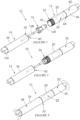
- FIG. 1 of the accompanying drawings depicts a wireless detonator initiating arrangement 10, according to the invention, in a disassembled configuration.
- the first module 12 comprises a first elongate tubular housing 20 in which is mounted a signal processing assembly 22.
- the assembly 22 includes an electromagnetic communication signal receiver 24 which is coupled to a receiving antenna 26 and a signal processor 28.
- the housing 20 has a first recess 30 concentrically positioned at an end 32.
- the second module 14 comprises a second housing 36 which is of elongate tubular shape.
- the housing 36 contains a secondary explosive 38.
- the module 14 constitutes a booster.
- the housing 36 has a second recess 40 which is concentrically positioned at an end 42 which faces the first recess 30.
- An end 44 of the housing 20 which is remote from the recess 30 can be coupled when required to a third housing 46 which contains a power source 50 e.g. a battery.
- a power source 50 e.g. a battery.
- the initiator 16 has a first end 16A and an opposed second end 16B.
- the initiator 16 and the second module 14 which houses the explosive 38 are hazardous goods. If these components are not connected to the first module 12 nor to the third housing 46 then the first module 12 and the third housing are not regarded as hazardous goods and can be transported and stored without taking into account regulations which apply to hazardous goods.
- the initiator 16 is mounted inside a custom-designed casing 52, which is shown in dotted outline in Figure 4 .
- the third housing 46 is coupled to the first housing 20 under factory conditions. To achieve this use is made of a simple screw fitting to fix the third housing 46 to the first housing 20.
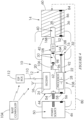
- a switch 54 mounted to the housing 20 is used to prevent the power source 50 from inadvertently energising the receiver 24 and the processor 28. Prior to installation and use at a blast bench the switch 54 is turned to an on position so that the power source 50 can energise the receiver 24 and the processor 28.
- electrical connections are made between contacts 56 connected to the power source 50 and contacts 58 connected to the processing assembly 22 but through the switch 54.
- the third housing 46 is connected on site to the housing 36, on a side 60 remote from the initiator 16, as is shown by a dotted line 80.
- This can be done by means of a screw fitting, or a bayonet connection.
- the contacts 56 on the power source 50 are thereby connected to contacts 84 on the housing 36.
- the contacts 88 are electrically connected to contacts 90 on the housing 20 and power is then available via a conductor 92 to operate the receiver 24 and the processor 28, which regulate firing of the initiator 16.
- the third housing 46 with the power source 50 is supplied as a separate component which is connected to the first housing 20, only when required, on site.
- Use can be made of the switch 54 to prevent the application of electricity to the receiver and processor until required.
- the switch 54 could be electronically controlled in that it is only operable when a signal from an external source, such as a blast controller 104, is received by the receiver. Thereafter, the receiver 24 and the processor 28, using energy harvesting techniques which recover energy from a signal, from the blast controller 104, induced into coils (not shown) at the receiver 24, actuate the switch 54 and the power source 50 is then fully connected to the first module 12.
- the end 16A of the initiator is configured to be inserted precisely into the recess 30 of the housing 20. An electrical connection is thereby made between terminals 96 connected to the processor 28 and operative electrical terminals 98 in the initiator 16.
- the second end 16B of the initiator 16 is configured to be inserted tightly into the recess 40 in the housing 36. As the recesses 30 and 40 are concentrically located, they oppose each other, and the first housing 20 can then be engaged with the second housing 36 with a screw action as is depicted in Figure 3 .
- the housing 36 at one end, includes one or more formations 100 which can be used to lower the assembled wireless initiating arrangement 10 shown in Figure 3 , suspended from a suitable cord, into a borehole (not shown) to a desired position.
- the switch 54 Prior thereto, if the switch 54 is not electrically actuable, as described hereinbefore, the switch 54 is manually operated to provide power to the arrangement 10.
- a wireless command signal sent from a blast controller 104 which is at a remote location relative to the arrangement 10, is received at the antenna 26 and passed to the receiver 24.
- Communication of this type is possible through the use of magnetic waves of a suitable amplitude and frequency which can reliably pass through a body of rock, which is not too sizeable, without undue attenuation.
- the processor 28 implements, in a known manner, any instruction contained in the command signal. As noted, if the switch 54 is electrically actuated a first signal which preferably is encoded would cause the switch 54 to be closed.
- the initiating arrangement is usually first brought into synchronism with other similar initiating arrangements in a blast system. Thereafter, when a fire command is received by the receiver 24, the processor 28, after a predetermined timing interval previously programmed into the processor, transmits a fire signal 106 to the initiator 16 which causes ignition thereof. That in turn causes ignition of the explosive 38.
- Power for the sequence of operations is derived from the power source 50 which energises the receiver 24 and the processor 28.
- Energy from the power source 50 can be stored in one or more capacitors 108 in the initiator 16 or in the processor 28 or in the initiator and in the processor. This enables a firing sequence to be executed automatically and independently of the power source 50 once a fire signal has been received by the receiver e.g. a programmed timing delay is processed and, thereafter, the detonator is ignited. This is an important feature for explosive shock waves, generated by other, previously fired, initiating arrangements could interfere with the supply of energy from the power source to the processor and to the initiator.
- the modular approach of the initiating arrangement 10 carries with it the significant advantages referred to hereinbefore, namely that assembly of the arrangement 10 on site at a blast bench is readily effected as the components are easily connected to one another. These components can only be connected in the manner shown; any attempt to connect the components to one another in a different manner would be unsuccessful.
- the initiating arrangement 10 allows for use to be made of a substantially standard detonator in the initiator 16.
- the initiator 16 and the second module 14 are kept separate from the first module 12 and the power supply 50 until such time as on-site assembly is required. This feature facilitates storage and transport requirements.
- the arrangement 10 is suspended in a borehole from conductors 110 which are connected to a top-box 112 positioned, for example, at a mouth of the borehole.
- the top-box 112 can communicate wirelessly with a blast controller, and via the conductors 110 with the arrangement 10, to control the blasting process.
Landscapes
- Engineering & Computer Science (AREA)
- General Engineering & Computer Science (AREA)
- Air Bags (AREA)
- Arrangements For Transmission Of Measured Signals (AREA)
- Selective Calling Equipment (AREA)
- Acyclic And Carbocyclic Compounds In Medicinal Compositions (AREA)
- Mobile Radio Communication Systems (AREA)
Claims (3)
- Eine Anordnung (10) zum Auslösen eines drahtlosen Zünders, die ein erstes Modul (12) mit einem ersten Gehäuse (20), das Kontakte (58) umfasst und in dem eine Signalverarbeitungsbaugruppe (24, 28) montiert ist, ein zweites Modul (14) mit einem zweiten Gehäuse (36), das mit dem ersten Gehäuse (20) in Eingriff gebracht werden kann und ein explosives Material (38) enthält, und einen Zünder (16), der mit mindestens dem ersten Gehäuse (20) in Eingriff gebracht werden kann, dadurch gekennzeichnet, dass der Zünder (16) ein erstes Ende (16A), das in einer ersten Aussparung (30) im ersten Gehäuse (20) angeordnet werden kann, und ein zweites Ende (16B) umfasst, das in einer zweiten Aussparung (40) in dem zweiten Gehäuse (36) angeordnet werden kann, dass die Anordnung (10) aus einem drahtlosen Zünder und einem Zünder außerdem ein drittes Gehäuse (46) mit Kontakten (56) umfasst, das eine Stromquelle (50) enthält und mit dem ersten Gehäuse (20) in Eingriff gebracht werden kann, wodurch die Kontakte (56) mit den Kontakten (58) verbunden werden, damit die Stromquelle (50) die Signalverarbeitungsbaugruppe (24, 28) mit Strom versorgen kann, und dass das erste Modul (12) einen Schalter (54) umfasst, der manuell oder elektrisch betätigt werden kann, um die Verbindung der Stromquelle (50) mit der Signalverarbeitungsbaugruppe (24, 28) zu steuern.
- Anordnung (10) zum Auslösen eines drahtlosen Zünders nach Anspruch 1, wobei der Zünder (16) in einem Gehäuse (52) montiert ist.
- Eine drahtlose Zündvorrichtung (10) gemäß Anspruch 1, die einen Kondensator (64) in mindestens einem von der Signalverarbeitungsbaugruppe (24, 28) und dem Zünder (16) umfasst, um die Ausführung einer Zündsequenz unabhängig von der Stromquelle zu ermöglichen, sobald ein Zündsignal vom Empfänger (24) empfangen wurde.
Applications Claiming Priority (2)
| Application Number | Priority Date | Filing Date | Title |
|---|---|---|---|
| ZA202106163 | 2021-08-24 | ||
| PCT/ZA2022/050028 WO2023028620A1 (en) | 2021-08-24 | 2022-07-07 | Wireless initiating arrangement |
Publications (2)
| Publication Number | Publication Date |
|---|---|
| EP4305375A1 EP4305375A1 (de) | 2024-01-17 |
| EP4305375B1 true EP4305375B1 (de) | 2025-04-02 |
Family
ID=82594605
Family Applications (1)
| Application Number | Title | Priority Date | Filing Date |
|---|---|---|---|
| EP22743695.3A Active EP4305375B1 (de) | 2021-08-24 | 2022-07-07 | Drahtlose initiierungsanordnung |
Country Status (11)
| Country | Link |
|---|---|
| US (1) | US12352552B2 (de) |
| EP (1) | EP4305375B1 (de) |
| AU (1) | AU2022334748A1 (de) |
| BR (1) | BR112023025922A2 (de) |
| CA (1) | CA3215232A1 (de) |
| CL (1) | CL2024000475A1 (de) |
| ES (1) | ES3034767T3 (de) |
| FI (1) | FI4305375T3 (de) |
| MX (1) | MX2023011085A (de) |
| WO (1) | WO2023028620A1 (de) |
| ZA (1) | ZA202308819B (de) |
Family Cites Families (13)
| Publication number | Priority date | Publication date | Assignee | Title |
|---|---|---|---|---|
| US3327792A (en) | 1965-10-22 | 1967-06-27 | Profitable Resources Inc | Jet perforating gun |
| US5263416A (en) | 1992-02-06 | 1993-11-23 | Alliant Techsystems Inc. | Primer propellant electrical ignition interconnect arrangement for single and multiple piece ammunition |
| US5531164A (en) | 1995-05-10 | 1996-07-02 | Titan Specialties, Inc. | Select fire gun assembly and electronic module for underground jet perforating using resistive blasting caps |
| US8136439B2 (en) | 2001-09-10 | 2012-03-20 | Bell William T | Explosive well tool firing head |
| US8091477B2 (en) | 2001-11-27 | 2012-01-10 | Schlumberger Technology Corporation | Integrated detonators for use with explosive devices |
| JP6109814B2 (ja) * | 2011-04-28 | 2017-04-05 | オリカ インターナショナル プライベート リミティド | 状態センサを有するワイヤレス起爆装置、爆破方法および雷管 |
| JP5849972B2 (ja) * | 2013-01-08 | 2016-02-03 | 日油株式会社 | 無線起爆雷管、親ダイ、無線起爆システム、及び無線起爆方法 |
| EP4481317A3 (de) * | 2015-09-16 | 2025-06-25 | Orica International Pte Ltd | Drahtlose initiierungsvorrichtung |
| US11255650B2 (en) | 2016-11-17 | 2022-02-22 | XConnect, LLC | Detonation system having sealed explosive initiation assembly |
| PE20220856A1 (es) * | 2019-10-23 | 2022-05-24 | Orica Int Pte Ltd | Sistemas y aparatos automatizados para almacenamiento, transporte, dispensacion y seguimiento de componentes de dispositivos de iniciacion configurables para iniciar composiciones de materiales explosivos |
| CA3141353C (en) * | 2020-04-29 | 2024-11-05 | Detnet South Africa (Pty) Ltd | WIRELESS DETONATOR KIT |
| ES2988295T3 (es) * | 2020-04-29 | 2024-11-20 | Detnet South Africa Pty Ltd | Sistema de voladura inalámbrico |
| US12405098B2 (en) * | 2021-08-24 | 2025-09-02 | Detnet South Africa (Pty) Ltd | Wireless detonator arrangement |
-
2022
- 2022-07-07 AU AU2022334748A patent/AU2022334748A1/en active Pending
- 2022-07-07 FI FIEP22743695.3T patent/FI4305375T3/fi active
- 2022-07-07 WO PCT/ZA2022/050028 patent/WO2023028620A1/en not_active Ceased
- 2022-07-07 EP EP22743695.3A patent/EP4305375B1/de active Active
- 2022-07-07 US US18/682,624 patent/US12352552B2/en active Active
- 2022-07-07 BR BR112023025922A patent/BR112023025922A2/pt unknown
- 2022-07-07 MX MX2023011085A patent/MX2023011085A/es unknown
- 2022-07-07 CA CA3215232A patent/CA3215232A1/en active Pending
- 2022-07-07 ES ES22743695T patent/ES3034767T3/es active Active
-
2023
- 2023-09-18 ZA ZA2023/08819A patent/ZA202308819B/en unknown
-
2024
- 2024-02-16 CL CL2024000475A patent/CL2024000475A1/es unknown
Also Published As
| Publication number | Publication date |
|---|---|
| MX2023011085A (es) | 2023-10-10 |
| CL2024000475A1 (es) | 2024-09-23 |
| EP4305375A1 (de) | 2024-01-17 |
| WO2023028620A1 (en) | 2023-03-02 |
| BR112023025922A2 (pt) | 2024-03-12 |
| CA3215232A1 (en) | 2023-03-02 |
| FI4305375T3 (fi) | 2025-06-03 |
| US20240361114A1 (en) | 2024-10-31 |
| ES3034767T3 (en) | 2025-08-22 |
| AU2022334748A1 (en) | 2023-10-05 |
| US12352552B2 (en) | 2025-07-08 |
| ZA202308819B (en) | 2024-10-30 |
Similar Documents
| Publication | Publication Date | Title |
|---|---|---|
| US6422145B1 (en) | Controlled electromagnetic induction detonation system for initiation of a detonatable material | |
| EP1809981B1 (de) | Drahtlose detonatoranordnungen, entsprechende sprengvorrichtungen und sprengverfahren | |
| EP3350539B1 (de) | Drahtlose startvorrichtung | |
| US4777880A (en) | Blasting method with above and below surface delays | |
| EP4305376B1 (de) | Drahtlose zünderanordnung | |
| EP4305375B1 (de) | Drahtlose initiierungsanordnung | |
| HK40106410A (en) | Wireless initiating arrangement | |
| HK40106410B (en) | Wireless initiating arrangement | |
| US20020178955A1 (en) | Controlled electromagnetic induction detonation system for initiation of a detonatable material | |
| AU2021106972A4 (en) | Wireless initiating arrangement | |
| HK40106104A (en) | Wireless detonator arrangement | |
| HK40106104B (en) | Wireless detonator arrangement | |
| AU2021106955A4 (en) | Wireless detonator arrangement | |
| EP0241151B1 (de) | Sprengvorrichtung | |
| CN113983886B (zh) | 遥控起爆销毁装置及其销毁方法 | |
| CN114719699A (zh) | 一种安全起爆装置 | |
| MXPA00004358A (es) | Sistema de detonacion por induccion electromagnetica controlada para la iniciacion de un material detonable | |
| HK1027618B (en) | Controlled electromagnetic induction detonation system for initiation of a detonatable material and method |
Legal Events
| Date | Code | Title | Description |
|---|---|---|---|
| STAA | Information on the status of an ep patent application or granted ep patent |
Free format text: STATUS: UNKNOWN |
|
| STAA | Information on the status of an ep patent application or granted ep patent |
Free format text: STATUS: THE INTERNATIONAL PUBLICATION HAS BEEN MADE |
|
| PUAI | Public reference made under article 153(3) epc to a published international application that has entered the european phase |
Free format text: ORIGINAL CODE: 0009012 |
|
| STAA | Information on the status of an ep patent application or granted ep patent |
Free format text: STATUS: REQUEST FOR EXAMINATION WAS MADE |
|
| 17P | Request for examination filed |
Effective date: 20231009 |
|
| AK | Designated contracting states |
Kind code of ref document: A1 Designated state(s): AL AT BE BG CH CY CZ DE DK EE ES FI FR GB GR HR HU IE IS IT LI LT LU LV MC MK MT NL NO PL PT RO RS SE SI SK SM TR |
|
| REG | Reference to a national code |
Ref country code: HK Ref legal event code: DE Ref document number: 40106410 Country of ref document: HK |
|
| GRAP | Despatch of communication of intention to grant a patent |
Free format text: ORIGINAL CODE: EPIDOSNIGR1 |
|
| STAA | Information on the status of an ep patent application or granted ep patent |
Free format text: STATUS: GRANT OF PATENT IS INTENDED |
|
| DAV | Request for validation of the european patent (deleted) | ||
| DAX | Request for extension of the european patent (deleted) | ||
| INTG | Intention to grant announced |
Effective date: 20241031 |
|
| GRAS | Grant fee paid |
Free format text: ORIGINAL CODE: EPIDOSNIGR3 |
|
| GRAA | (expected) grant |
Free format text: ORIGINAL CODE: 0009210 |
|
| STAA | Information on the status of an ep patent application or granted ep patent |
Free format text: STATUS: THE PATENT HAS BEEN GRANTED |
|
| AK | Designated contracting states |
Kind code of ref document: B1 Designated state(s): AL AT BE BG CH CY CZ DE DK EE ES FI FR GB GR HR HU IE IS IT LI LT LU LV MC MK MT NL NO PL PT RO RS SE SI SK SM TR |
|
| REG | Reference to a national code |
Ref country code: GB Ref legal event code: FG4D |
|
| REG | Reference to a national code |
Ref country code: CH Ref legal event code: EP |
|
| REG | Reference to a national code |
Ref country code: IE Ref legal event code: FG4D |
|
| REG | Reference to a national code |
Ref country code: DE Ref legal event code: R096 Ref document number: 602022012654 Country of ref document: DE |
|
| REG | Reference to a national code |
Ref country code: FI Ref legal event code: FGE |
|
| REG | Reference to a national code |
Ref country code: SE Ref legal event code: TRGR |
|
| REG | Reference to a national code |
Ref country code: NL Ref legal event code: MP Effective date: 20250402 |
|
| REG | Reference to a national code |
Ref country code: ES Ref legal event code: FG2A Ref document number: 3034767 Country of ref document: ES Kind code of ref document: T3 Effective date: 20250822 |
|
| PG25 | Lapsed in a contracting state [announced via postgrant information from national office to epo] |
Ref country code: NL Free format text: LAPSE BECAUSE OF FAILURE TO SUBMIT A TRANSLATION OF THE DESCRIPTION OR TO PAY THE FEE WITHIN THE PRESCRIBED TIME-LIMIT Effective date: 20250402 |
|
| REG | Reference to a national code |
Ref country code: AT Ref legal event code: MK05 Ref document number: 1781648 Country of ref document: AT Kind code of ref document: T Effective date: 20250402 |
|
| PG25 | Lapsed in a contracting state [announced via postgrant information from national office to epo] |
Ref country code: PT Free format text: LAPSE BECAUSE OF FAILURE TO SUBMIT A TRANSLATION OF THE DESCRIPTION OR TO PAY THE FEE WITHIN THE PRESCRIBED TIME-LIMIT Effective date: 20250804 |
|
| PGFP | Annual fee paid to national office [announced via postgrant information from national office to epo] |
Ref country code: ES Payment date: 20250819 Year of fee payment: 4 Ref country code: FI Payment date: 20250722 Year of fee payment: 4 |
|
| REG | Reference to a national code |
Ref country code: LT Ref legal event code: MG9D |
|
| PG25 | Lapsed in a contracting state [announced via postgrant information from national office to epo] |
Ref country code: GR Free format text: LAPSE BECAUSE OF FAILURE TO SUBMIT A TRANSLATION OF THE DESCRIPTION OR TO PAY THE FEE WITHIN THE PRESCRIBED TIME-LIMIT Effective date: 20250703 Ref country code: NO Free format text: LAPSE BECAUSE OF FAILURE TO SUBMIT A TRANSLATION OF THE DESCRIPTION OR TO PAY THE FEE WITHIN THE PRESCRIBED TIME-LIMIT Effective date: 20250702 |
|
| PG25 | Lapsed in a contracting state [announced via postgrant information from national office to epo] |
Ref country code: PL Free format text: LAPSE BECAUSE OF FAILURE TO SUBMIT A TRANSLATION OF THE DESCRIPTION OR TO PAY THE FEE WITHIN THE PRESCRIBED TIME-LIMIT Effective date: 20250402 |
|
| PG25 | Lapsed in a contracting state [announced via postgrant information from national office to epo] |
Ref country code: BG Free format text: LAPSE BECAUSE OF FAILURE TO SUBMIT A TRANSLATION OF THE DESCRIPTION OR TO PAY THE FEE WITHIN THE PRESCRIBED TIME-LIMIT Effective date: 20250402 |
|
| PG25 | Lapsed in a contracting state [announced via postgrant information from national office to epo] |
Ref country code: HR Free format text: LAPSE BECAUSE OF FAILURE TO SUBMIT A TRANSLATION OF THE DESCRIPTION OR TO PAY THE FEE WITHIN THE PRESCRIBED TIME-LIMIT Effective date: 20250402 |
|
| PG25 | Lapsed in a contracting state [announced via postgrant information from national office to epo] |
Ref country code: AT Free format text: LAPSE BECAUSE OF FAILURE TO SUBMIT A TRANSLATION OF THE DESCRIPTION OR TO PAY THE FEE WITHIN THE PRESCRIBED TIME-LIMIT Effective date: 20250402 |
|
| PGFP | Annual fee paid to national office [announced via postgrant information from national office to epo] |
Ref country code: FR Payment date: 20250723 Year of fee payment: 4 |
|
| PGFP | Annual fee paid to national office [announced via postgrant information from national office to epo] |
Ref country code: SE Payment date: 20250723 Year of fee payment: 4 |
|
| PG25 | Lapsed in a contracting state [announced via postgrant information from national office to epo] |
Ref country code: RS Free format text: LAPSE BECAUSE OF FAILURE TO SUBMIT A TRANSLATION OF THE DESCRIPTION OR TO PAY THE FEE WITHIN THE PRESCRIBED TIME-LIMIT Effective date: 20250702 |
|
| PG25 | Lapsed in a contracting state [announced via postgrant information from national office to epo] |
Ref country code: IS Free format text: LAPSE BECAUSE OF FAILURE TO SUBMIT A TRANSLATION OF THE DESCRIPTION OR TO PAY THE FEE WITHIN THE PRESCRIBED TIME-LIMIT Effective date: 20250802 |
|
| PG25 | Lapsed in a contracting state [announced via postgrant information from national office to epo] |
Ref country code: LV Free format text: LAPSE BECAUSE OF FAILURE TO SUBMIT A TRANSLATION OF THE DESCRIPTION OR TO PAY THE FEE WITHIN THE PRESCRIBED TIME-LIMIT Effective date: 20250402 |