EP4303897A1 - Magnetic core - Google Patents
Magnetic core Download PDFInfo
- Publication number
- EP4303897A1 EP4303897A1 EP22275090.3A EP22275090A EP4303897A1 EP 4303897 A1 EP4303897 A1 EP 4303897A1 EP 22275090 A EP22275090 A EP 22275090A EP 4303897 A1 EP4303897 A1 EP 4303897A1
- Authority
- EP
- European Patent Office
- Prior art keywords
- core
- sections
- magnetic core
- core section
- complementary
- Prior art date
- Legal status (The legal status is an assumption and is not a legal conclusion. Google has not performed a legal analysis and makes no representation as to the accuracy of the status listed.)
- Pending
Links
Images

Classifications
-
- H—ELECTRICITY
- H01—ELECTRIC ELEMENTS
- H01F—MAGNETS; INDUCTANCES; TRANSFORMERS; SELECTION OF MATERIALS FOR THEIR MAGNETIC PROPERTIES
- H01F27/00—Details of transformers or inductances, in general
- H01F27/24—Magnetic cores
- H01F27/26—Fastening parts of the core together; Fastening or mounting the core on casing or support
- H01F27/263—Fastening parts of the core together
-
- H—ELECTRICITY
- H01—ELECTRIC ELEMENTS
- H01F—MAGNETS; INDUCTANCES; TRANSFORMERS; SELECTION OF MATERIALS FOR THEIR MAGNETIC PROPERTIES
- H01F27/00—Details of transformers or inductances, in general
- H01F27/24—Magnetic cores
- H01F27/245—Magnetic cores made from sheets, e.g. grain-oriented
-
- H—ELECTRICITY
- H01—ELECTRIC ELEMENTS
- H01F—MAGNETS; INDUCTANCES; TRANSFORMERS; SELECTION OF MATERIALS FOR THEIR MAGNETIC PROPERTIES
- H01F27/00—Details of transformers or inductances, in general
- H01F27/28—Coils; Windings; Conductive connections
- H01F27/2823—Wires
-
- H—ELECTRICITY
- H01—ELECTRIC ELEMENTS
- H01F—MAGNETS; INDUCTANCES; TRANSFORMERS; SELECTION OF MATERIALS FOR THEIR MAGNETIC PROPERTIES
- H01F3/00—Cores, Yokes, or armatures
- H01F3/10—Composite arrangements of magnetic circuits
- H01F3/14—Constrictions; Gaps, e.g. air-gaps
-
- H—ELECTRICITY
- H01—ELECTRIC ELEMENTS
- H01F—MAGNETS; INDUCTANCES; TRANSFORMERS; SELECTION OF MATERIALS FOR THEIR MAGNETIC PROPERTIES
- H01F30/00—Fixed transformers not covered by group H01F19/00
- H01F30/06—Fixed transformers not covered by group H01F19/00 characterised by the structure
-
- H—ELECTRICITY
- H01—ELECTRIC ELEMENTS
- H01F—MAGNETS; INDUCTANCES; TRANSFORMERS; SELECTION OF MATERIALS FOR THEIR MAGNETIC PROPERTIES
- H01F41/00—Apparatus or processes specially adapted for manufacturing or assembling magnets, inductances or transformers; Apparatus or processes specially adapted for manufacturing materials characterised by their magnetic properties
- H01F41/02—Apparatus or processes specially adapted for manufacturing or assembling magnets, inductances or transformers; Apparatus or processes specially adapted for manufacturing materials characterised by their magnetic properties for manufacturing cores, coils, or magnets
- H01F41/0206—Manufacturing of magnetic cores by mechanical means
- H01F41/0233—Manufacturing of magnetic circuits made from sheets
Definitions
- the present disclosure relates to a magnetic core design for transformers or inductors.
- Transformers are used in many electrical systems to transform voltage or current at one level to voltage and/or current at a different level.
- a transformer consists of one or more windings or coils of conductive material e.g. electrically insulated copper, wound around a ferrous or magnetic core such that current flow through one winding or part of a winding will induce current flow through another winding or part of a winding.
- Many systems e.g. power converters used in applications such as aircraft, convert AC power to DC power to drive DC loads.
- Three-phase transformers made from very thin laminated sheets of silicon steel or amorphous iron material are commonly used in medium to high power AC/DC power conversion systems. These transformers are suitable for operating frequencies of 200Hz to 2 kHz because they have low core loss and very high flux saturation characteristics.
- Auto-transformers which only have a single winding acting as both the primary and the secondary winding of the system. Auto-transformers are used, for example, in power conversion systems on aircraft to provide power to the various electric loads.
- Transformer and inductor cores may have different shapes. Common shapes are E, I, C or U. E and I shaped cores may be combined as EE or EI shaped cores. Two C or U shaped cores, or a C or U and an I shaped core may be combined to an O shaped or oval core.
- the windings are generally wound onto bobbins first before being assembled together with the cores - onto the core legs. For combined EE or EI cores, the core parts are then typically held together by metal straps, with the bobbins provided around the adjoining legs.
- a disadvantage of these conventional methods and designs is that the bobbins around which the windings have to be wound to keep then around the adjoining core parts that form the core legs take up space in the transformer that could otherwise be used for more windings. Further, the bobbins limit effective heat transfer between the windings and the cores.
- the manufacturing and assembly process of these conventional designs requires the three steps of machining the transformer coil, winding the conductors onto the bobbin and assembling the core parts and the bobbins. The parts then have to be secured together by the metal strap or other mechanical fastening means which adds a further assembly step and also adds to the overall weight of the core.
- a magnetic core section comprising a substantially rectangular core section body having opposing sides joined by opposing ends, and further comprising interlocking features provided at each of the ends, shaped to interlock with interlocking features of complementary core sections.
- FIG. 1 shows a typical EE core design.
- the core comprises two complementary E-shaped core sections 2a, 2b each having a spine 21a, 21b from which three legs 22 a, 22b extend.
- the two E-shapes are assembled such that their respective legs 22a, 22b align and abut.
- Each core section 2a, 2b is made of a stack of thin laminated sheets locked, glued, welded etc. together as is known in the art.
- the transformer windings 1 are formed by winding conductive wires e.g. electrically insulated copper wires wound onto a bobbin. This is not shown in detail as it is well known in the art.
- Each winding 1 i.e.
- the present disclosure provides a transformer core section onto which conductors may be fitted already wound onto a bobbin, as is conventional, but also provides the possibility of directly winding the conductive wire onto the core section without the need for a bobbin. In some cases, extra electrical insulation, but highly thermally conductive material, such as thin sheets or films can also be put on the core prior to the winding process.
- the core section is in the form of a substantially rectangular block having sides 20a, 20b joined by ends 20c, 20d.
- the ends 20c. 20d are provided with interlocking features that can interlock with complementary features in other core parts to form the desired transformer core shape.
- the core section 20 may be fabricated in a manner similar to conventional core sections in that it comprises several laminated sheets 201 stacked together and secured by interlocking, gluing, welding etc. In other examples, however, the core section may be fabricated as a solid block.
- the core section 20 can then be prepared by providing the winding 11 around it (either on a bobbin or by directly winding the conductor onto the core section).
- the wound core section is then fitted to complementary core sections 12a, 12b by means of the matching interlocking features 30a, 30b at the ends of the core section which engage and interlock with matching features 40a, 40b of the complementary core sections 12a, 12b.
- the interlocking features 30a, 30b are shaped to interlock - i.e. to fit into and secure to interlocking shapes 40a, 40b on the complementary core sections.
- One example is shown in Figs. 2A and 2B where the interlocking feature on each end of the core section 20 is formed as a tooth defining a notch 301 on either side. This can then lock into a correspondingly shaped recesses 40a, 40b formed in the complementary core section.
- the sides of the tooth may be tapered outwards in the direction away from the end of the core section to secure the core sections against relative axial (direction A) movement when the core section 20 is slotted into place between the complementary core sections and its teeth 30a, 30b are slotted into the recesses 40a, 40b.
- the core can be formed with sufficient gaps between the core sections to prevent flux saturation due to any imbalances and DC flux. In preferred assemblies the gaps may be large enough to be within the tolerance capability of standard transformer machining tools (e.g. 50 ⁇ m) .
- the interlocking features may be in the form of a T-shaped protrusion 30'a, 30'b or 30"a, 30"b extending from the end of the core section 20' or 20", this defining detents 32'a, 32'b; 32"a, 32"b between the bar of the T and the end of the core section.
- the complementary sections 12'a, 12'b would then have respecting C-shaped interlocking features 40'a, 40'b to lock around the end of the T and secure in the detents.
- the complementary T-shaped and C-shaped interlocking features lock the core section and the complementary section together in both direction A (up and down when viewing the drawings) and direction B (side to side when viewing the drawings).
- the sections can move relative to each other in direction C (into and out of the page) for assembly - sliding the T-shaped features into the C-shaped features. If desired, this movement can be blocked after assembly by some housing component e.g. a lightweight cap or some form of clamp or the like.
- a lightweight cap or some form of clamp or the like can add to the size/weight/volume of the design but, if designed well, can provide thermal conduction enhancement to the transformer/inductor depending on operating conditions or environment.
- an air gap 400 may be formed between two halves 120a', 120b'.
- An air gap 400 may be provided in core sections having interlocking features other than the T-shaped protrusions shown in Fig. 3B . This feature allows the air gap to be controlled to contribute to preventing magnetic flux saturation. Without this air gap, the transformer can only rely on the tolerance between parts 20' and 12'a and parts 20' and 12'b to stop the flux saturation, which is the main constraint in manufacturing the transformer core design. Other interlocking features may also be envisaged.
- the core section having interlocking features extending from the ends which interlock with recessed interlocking features of the complementary core sections, it is feasible that the interlocking features of the core section are recessed with respect to the ends and interlock with protruding interlocking features of the complementary core sections.
- the core section can be easily manufactured by stamping the required shape from sheet metal. Also, EE shaped cores, for example, can be formed from only I shaped sections which simplifies manufacture.
Landscapes
- Engineering & Computer Science (AREA)
- Power Engineering (AREA)
- Chemical & Material Sciences (AREA)
- Composite Materials (AREA)
- Manufacturing & Machinery (AREA)
- Coils Or Transformers For Communication (AREA)
Abstract
Description
- The present disclosure relates to a magnetic core design for transformers or inductors.
- Transformers are used in many electrical systems to transform voltage or current at one level to voltage and/or current at a different level. A transformer consists of one or more windings or coils of conductive material e.g. electrically insulated copper, wound around a ferrous or magnetic core such that current flow through one winding or part of a winding will induce current flow through another winding or part of a winding. Many systems e.g. power converters used in applications such as aircraft, convert AC power to DC power to drive DC loads. Three-phase transformers made from very thin laminated sheets of silicon steel or amorphous iron material are commonly used in medium to high power AC/DC power conversion systems. These transformers are suitable for operating frequencies of 200Hz to 2 kHz because they have low core loss and very high flux saturation characteristics. To reduce harmonics in such systems, it has become common to use autotransformers which only have a single winding acting as both the primary and the secondary winding of the system. Auto-transformers are used, for example, in power conversion systems on aircraft to provide power to the various electric loads.
- Transformer and inductor cores may have different shapes. Common shapes are E, I, C or U. E and I shaped cores may be combined as EE or EI shaped cores. Two C or U shaped cores, or a C or U and an I shaped core may be combined to an O shaped or oval core. The windings are generally wound onto bobbins first before being assembled together with the cores - onto the core legs. For combined EE or EI cores, the core parts are then typically held together by metal straps, with the bobbins provided around the adjoining legs.
- A disadvantage of these conventional methods and designs is that the bobbins around which the windings have to be wound to keep then around the adjoining core parts that form the core legs take up space in the transformer that could otherwise be used for more windings. Further, the bobbins limit effective heat transfer between the windings and the cores. The manufacturing and assembly process of these conventional designs requires the three steps of machining the transformer coil, winding the conductors onto the bobbin and assembling the core parts and the bobbins. The parts then have to be secured together by the metal strap or other mechanical fastening means which adds a further assembly step and also adds to the overall weight of the core.
- Whilst these traditional designs work well as transformers in most cases, it would be desirable to provide a core design that overcomes some or all of these disadvantages.
- According to the present disclosure, there is provided a magnetic core section comprising a substantially rectangular core section body having opposing sides joined by opposing ends, and further comprising interlocking features provided at each of the ends, shaped to interlock with interlocking features of complementary core sections.
- Also provided is a magnetic core, a method of manufacturing a magnetic core section and a method of assembling a magnetic core.
- Examples will now be described with reference to the drawings. It should be noted that these are examples only and that variations are possible within the scope of the claims. The description will focus on transformer cores, but the principles apply equally to inductor cores.
-
Figure 1 shows an examples of a conventional EE core design for the purposes of background. -
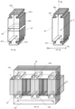
Figure 2A shows an example of a core section in accordance with the disclosure. -
Figure 2B shows the core section ofFig. 2A fitted with complementary core sections to form an EE core design. -
Figure 3A shows an example of an alternative core section in accordance with the disclosure. -
Figure 3B shows an example of an alternative core section in accordance with the disclosure. -
Figure 3C shows the core section ofFig. 3A or 3B fitted with complementary core sections to form an EE core design. -
Figure 1 shows a typical EE core design. The core comprises two complementaryE-shaped core sections spine 21a, 21b from which threelegs respective legs core section Fig. 1 . The hold the assembly together, clamps or straps would be fastened around the core sections (not shown here, but well-known in the art). Similar principles apply to transformer cores made by combining other core section shapes e.g. I, C or U shapes. - The present disclosure provides a transformer core section onto which conductors may be fitted already wound onto a bobbin, as is conventional, but also provides the possibility of directly winding the conductive wire onto the core section without the need for a bobbin. In some cases, extra electrical insulation, but highly thermally conductive material, such as thin sheets or films can also be put on the core prior to the winding process. The core section is in the form of a substantially rectangular
block having sides ends ends 20c. 20d are provided with interlocking features that can interlock with complementary features in other core parts to form the desired transformer core shape. Thecore section 20 may be fabricated in a manner similar to conventional core sections in that it comprises several laminatedsheets 201 stacked together and secured by interlocking, gluing, welding etc. In other examples, however, the core section may be fabricated as a solid block. Thecore section 20 can then be prepared by providing the winding 11 around it (either on a bobbin or by directly winding the conductor onto the core section). The wound core section is then fitted tocomplementary core sections matching features complementary core sections - Whilst the examples shown here combine the
core section 20 with twocomplementary sections - The interlocking features 30a, 30b are shaped to interlock - i.e. to fit into and secure to interlocking
shapes Figs. 2A and 2B where the interlocking feature on each end of thecore section 20 is formed as a tooth defining anotch 301 on either side. This can then lock into a correspondinglyshaped recesses core section 20 is slotted into place between the complementary core sections and itsteeth recesses Fig. 2B , threesuch core sections 20 are assembled between two substantially I shapedcomplementary sections core section 20 of this disclosure effective replaces theabutting legs Fig. 1 . Because it is not essential to provide the windings on bobbins before assembly, the core can be formed with sufficient gaps between the core sections to prevent flux saturation due to any imbalances and DC flux. In preferred assemblies the gaps may be large enough to be within the tolerance capability of standard transformer machining tools (e.g. 50 µm) . - In an alternative example, as shown in
Fig. 3A and 3B , the interlocking features may be in the form of a T-shaped protrusion 30'a, 30'b or 30"a, 30"b extending from the end of thecore section 20' or 20", this defining detents 32'a, 32'b; 32"a, 32"b between the bar of the T and the end of the core section. The complementary sections 12'a, 12'b would then have respecting C-shaped interlocking features 40'a, 40'b to lock around the end of the T and secure in the detents. A benefit of this embodiment compared to that ofFigs. 2A and 2B is that the complementary T-shaped and C-shaped interlocking features lock the core section and the complementary section together in both direction A (up and down when viewing the drawings) and direction B (side to side when viewing the drawings). The sections can move relative to each other in direction C (into and out of the page) for assembly - sliding the T-shaped features into the C-shaped features. If desired, this movement can be blocked after assembly by some housing component e.g. a lightweight cap or some form of clamp or the like. Such a cap or clamp or the like can add to the size/weight/volume of the design but, if designed well, can provide thermal conduction enhancement to the transformer/inductor depending on operating conditions or environment. - In the example shown in
Fig. 3B , anair gap 400 may be formed between twohalves 120a', 120b'. Anair gap 400 may be provided in core sections having interlocking features other than the T-shaped protrusions shown inFig. 3B . This feature allows the air gap to be controlled to contribute to preventing magnetic flux saturation. Without this air gap, the transformer can only rely on the tolerance between parts 20' and 12'a and parts 20' and 12'b to stop the flux saturation, which is the main constraint in manufacturing the transformer core design. Other interlocking features may also be envisaged. Whilst the examples show the core section having interlocking features extending from the ends which interlock with recessed interlocking features of the complementary core sections, it is feasible that the interlocking features of the core section are recessed with respect to the ends and interlock with protruding interlocking features of the complementary core sections. - Fewer steps are required to manufacture and assemble the core using the
core section - The core section can be easily manufactured by stamping the required shape from sheet metal. Also, EE shaped cores, for example, can be formed from only I shaped sections which simplifies manufacture.
Claims (14)
- A magnetic core section comprising a substantially rectangular core section body having opposing sides (20a, 20b) joined by opposing ends (20c, 20d), and further comprising interlocking features (30a, 30b) provided at each of the ends, shaped to interlock with interlocking features of complementary core sections (12a, 12b).
- The magnetic core section of claim 1, wherein the core section body is formed of a plurality of laminated sheets stacked together.
- The magnetic section of claim 1 or 2, wherein the interlocking features (30a, 30b) are in the form of teeth extending from the ends.
- The magnetic core section of claim 3, wherein the teeth have tapered sides.
- The magnetic core section of claim 1 or 3, wherein the interlocking features (30'a, 30'b, 30"a, 30"b) are in the form of T-shaped protrusions extending from the ends.
- The magnetic core section of any preceding claim wherein the core section body comprises two parts (120a', 120b') separated by an air gap (400).
- The magnetic core section of any preceding claim, further comprising a winding (11) of conductive material wound around the body.
- The magnetic core section of any preceding claim, being a core section of a transformer or an inductor.
- A magnetic core comprising one or more magnetic core sections as claimed in any preceding claim and two complementary core sections (12a, 12b), the one or more magnetic core sections fitted between and interlocking with the complementary core sections by interlocking engagement of the interlocking features at the ends of the core section with the interlocking features of the complementary core sections.
- The magnetic core of claim 9, comprising two magnetic core sections as claimed in any of claims 1 to 8 and wherein the complementary core sections each have two interlocking features.
- The magnetic core of claim 9, comprising three magnetic core sections as claimed in any of claims 1 to 8 and wherein the complementary core sections each have three interlocking features to form an EE core.
- A method of manufacturing a magnetic core section as claimed in any of claims 1 to 8, comprising stamping the shape of the body and the interlocking features from sheet metal to form a shaped laminate and stacking a plurality of the shaped laminates to form the core section body.
- The method of claim 11, further comprising winding a conductive wire around the core section body to form a transformer or inductor winding.
- A method of assembling a transformer core comprising:manufacturing one or more magnetic core sections as claimed in claim 13; providing two complementary core sections; andinterlocking the one or more magnetic sections between the two complementary core sections by engaging corresponding interlocking features.
Priority Applications (2)
| Application Number | Priority Date | Filing Date | Title |
|---|---|---|---|
| EP22275090.3A EP4303897A1 (en) | 2022-07-07 | 2022-07-07 | Magnetic core |
| US18/348,432 US20240013965A1 (en) | 2022-07-07 | 2023-07-07 | Magnetic core |
Applications Claiming Priority (1)
| Application Number | Priority Date | Filing Date | Title |
|---|---|---|---|
| EP22275090.3A EP4303897A1 (en) | 2022-07-07 | 2022-07-07 | Magnetic core |
Publications (1)
| Publication Number | Publication Date |
|---|---|
| EP4303897A1 true EP4303897A1 (en) | 2024-01-10 |
Family
ID=82458631
Family Applications (1)
| Application Number | Title | Priority Date | Filing Date |
|---|---|---|---|
| EP22275090.3A Pending EP4303897A1 (en) | 2022-07-07 | 2022-07-07 | Magnetic core |
Country Status (2)
| Country | Link |
|---|---|
| US (1) | US20240013965A1 (en) |
| EP (1) | EP4303897A1 (en) |
Citations (5)
| Publication number | Priority date | Publication date | Assignee | Title |
|---|---|---|---|---|
| FR2494026A2 (en) * | 1980-11-12 | 1982-05-14 | Marchal Equip Auto | JUNCTION ELEMENT FOR ADJUSTING A MAGNETIC GAP AND MAGNETIC DEVICE COMPRISING SAME |
| DE3138564A1 (en) * | 1981-09-28 | 1983-04-07 | Transformatoren Union Ag, 7000 Stuttgart | Iron core for transformers |
| US20050237145A1 (en) * | 2004-04-26 | 2005-10-27 | Sumida Corporation | High-voltage transformer |
| US20060158303A1 (en) * | 2005-01-14 | 2006-07-20 | Lincoln Global, Inc. | Snap-together choke and transformer assembly for an electric arc welder |
| US20140028431A1 (en) * | 2011-04-08 | 2014-01-30 | Amogreentech Co., Ltd. | Amorphous metal core, induction apparatus using same, and method for manufacturing same |
-
2022
- 2022-07-07 EP EP22275090.3A patent/EP4303897A1/en active Pending
-
2023
- 2023-07-07 US US18/348,432 patent/US20240013965A1/en active Pending
Patent Citations (5)
| Publication number | Priority date | Publication date | Assignee | Title |
|---|---|---|---|---|
| FR2494026A2 (en) * | 1980-11-12 | 1982-05-14 | Marchal Equip Auto | JUNCTION ELEMENT FOR ADJUSTING A MAGNETIC GAP AND MAGNETIC DEVICE COMPRISING SAME |
| DE3138564A1 (en) * | 1981-09-28 | 1983-04-07 | Transformatoren Union Ag, 7000 Stuttgart | Iron core for transformers |
| US20050237145A1 (en) * | 2004-04-26 | 2005-10-27 | Sumida Corporation | High-voltage transformer |
| US20060158303A1 (en) * | 2005-01-14 | 2006-07-20 | Lincoln Global, Inc. | Snap-together choke and transformer assembly for an electric arc welder |
| US20140028431A1 (en) * | 2011-04-08 | 2014-01-30 | Amogreentech Co., Ltd. | Amorphous metal core, induction apparatus using same, and method for manufacturing same |
Also Published As
| Publication number | Publication date |
|---|---|
| US20240013965A1 (en) | 2024-01-11 |
Similar Documents
| Publication | Publication Date | Title |
|---|---|---|
| US8031042B2 (en) | Power converter magnetic devices | |
| US8570133B2 (en) | Transformer | |
| EP2677526B1 (en) | Integrated magnetics for switched mode power converter | |
| US20100091522A1 (en) | Extended E Matrix Integrated Magnetics (MIM) Core | |
| WO2013065095A1 (en) | Reactor, transformer, and power conversion apparatus using same | |
| JP7515688B2 (en) | Magnetic components with suppressed leakage flux | |
| WO2012157053A1 (en) | Reactor device and power converter employing same | |
| CN103003894B (en) | Polyphase transformer and transformation system | |
| KR101853795B1 (en) | Low loss and reduced-weight type transformer and manufacturing method thereof | |
| JPS62222614A (en) | Composite core of silicon steel-amorphous steel for transformer | |
| US20230395313A1 (en) | Heat transfer from transformer windings | |
| JP3200723U (en) | Rapidly assembled transformer and its asymmetric two-part wound core structure | |
| WO2019013131A1 (en) | Planar transformer and dcdc converter | |
| US4012706A (en) | Sheet-wound transformer coils | |
| US20230360850A1 (en) | Converter component and converter | |
| JP2002353045A (en) | Power transformer and power converter comprising it | |
| US20240013965A1 (en) | Magnetic core | |
| US20210082609A1 (en) | Common-mode/differential-mode throttle for an electrically driveable motor vehicle | |
| US10186370B1 (en) | Transformers with integrated inductors | |
| JP2008270347A (en) | Transformer | |
| US20230008213A1 (en) | Electrotechnical device for an aircraft, comprising low-frequency coil components | |
| US20230033439A1 (en) | Electrotechnical device for an aircraft | |
| US20250149229A1 (en) | Integrated magnetic component and llc resonant converters | |
| JP7773595B2 (en) | reactor | |
| JP2001230134A (en) | Assembly method of shell-type reactor and core for shell-type reactor |
Legal Events
| Date | Code | Title | Description |
|---|---|---|---|
| PUAI | Public reference made under article 153(3) epc to a published international application that has entered the european phase |
Free format text: ORIGINAL CODE: 0009012 |
|
| STAA | Information on the status of an ep patent application or granted ep patent |
Free format text: STATUS: THE APPLICATION HAS BEEN PUBLISHED |
|
| AK | Designated contracting states |
Kind code of ref document: A1 Designated state(s): AL AT BE BG CH CY CZ DE DK EE ES FI FR GB GR HR HU IE IS IT LI LT LU LV MC MK MT NL NO PL PT RO RS SE SI SK SM TR |
|
| STAA | Information on the status of an ep patent application or granted ep patent |
Free format text: STATUS: REQUEST FOR EXAMINATION WAS MADE |
|
| 17P | Request for examination filed |
Effective date: 20240710 |
|
| RBV | Designated contracting states (corrected) |
Designated state(s): AL AT BE BG CH CY CZ DE DK EE ES FI FR GB GR HR HU IE IS IT LI LT LU LV MC MK MT NL NO PL PT RO RS SE SI SK SM TR |