EP4303619A2 - Laser scanner - Google Patents
Laser scanner Download PDFInfo
- Publication number
- EP4303619A2 EP4303619A2 EP23212138.4A EP23212138A EP4303619A2 EP 4303619 A2 EP4303619 A2 EP 4303619A2 EP 23212138 A EP23212138 A EP 23212138A EP 4303619 A2 EP4303619 A2 EP 4303619A2
- Authority
- EP
- European Patent Office
- Prior art keywords
- support
- laser scanner
- rotation
- data
- axis
- Prior art date
- Legal status (The legal status is an assumption and is not a legal conclusion. Google has not performed a legal analysis and makes no representation as to the accuracy of the status listed.)
- Pending
Links
- 238000005259 measurement Methods 0.000 claims description 288
- 230000005855 radiation Effects 0.000 claims description 146
- 230000003287 optical effect Effects 0.000 claims description 101
- 238000000034 method Methods 0.000 claims description 92
- 230000008569 process Effects 0.000 claims description 87
- 238000012545 processing Methods 0.000 claims description 32
- 230000000694 effects Effects 0.000 claims description 24
- 230000008878 coupling Effects 0.000 claims description 21
- 238000010168 coupling process Methods 0.000 claims description 21
- 238000005859 coupling reaction Methods 0.000 claims description 21
- 230000003993 interaction Effects 0.000 claims description 6
- 230000002045 lasting effect Effects 0.000 claims description 5
- 230000003213 activating effect Effects 0.000 claims description 2
- 230000001960 triggered effect Effects 0.000 claims description 2
- 230000006641 stabilisation Effects 0.000 description 43
- 238000011105 stabilization Methods 0.000 description 43
- 238000006243 chemical reaction Methods 0.000 description 33
- 230000005540 biological transmission Effects 0.000 description 21
- 238000012360 testing method Methods 0.000 description 21
- 238000005096 rolling process Methods 0.000 description 17
- 238000005070 sampling Methods 0.000 description 13
- 210000001015 abdomen Anatomy 0.000 description 12
- 230000010354 integration Effects 0.000 description 8
- 230000035515 penetration Effects 0.000 description 8
- 238000013461 design Methods 0.000 description 7
- 238000003860 storage Methods 0.000 description 7
- 230000008859 change Effects 0.000 description 6
- 238000009795 derivation Methods 0.000 description 6
- 230000004913 activation Effects 0.000 description 5
- 238000012937 correction Methods 0.000 description 5
- 238000005520 cutting process Methods 0.000 description 5
- 230000005484 gravity Effects 0.000 description 5
- 238000005286 illumination Methods 0.000 description 5
- 230000036316 preload Effects 0.000 description 5
- 238000001514 detection method Methods 0.000 description 4
- 239000000839 emulsion Substances 0.000 description 4
- 239000000314 lubricant Substances 0.000 description 4
- 239000004033 plastic Substances 0.000 description 4
- 239000005871 repellent Substances 0.000 description 4
- 230000035945 sensitivity Effects 0.000 description 4
- 230000003190 augmentative effect Effects 0.000 description 3
- 230000001419 dependent effect Effects 0.000 description 3
- 230000001976 improved effect Effects 0.000 description 3
- 238000012544 monitoring process Methods 0.000 description 3
- 238000002310 reflectometry Methods 0.000 description 3
- 230000008054 signal transmission Effects 0.000 description 3
- 239000000853 adhesive Substances 0.000 description 2
- 230000001070 adhesive effect Effects 0.000 description 2
- 238000013459 approach Methods 0.000 description 2
- 230000008901 benefit Effects 0.000 description 2
- 239000000919 ceramic Substances 0.000 description 2
- 230000003750 conditioning effect Effects 0.000 description 2
- 238000010276 construction Methods 0.000 description 2
- 238000006073 displacement reaction Methods 0.000 description 2
- 230000009977 dual effect Effects 0.000 description 2
- 239000000463 material Substances 0.000 description 2
- 238000003825 pressing Methods 0.000 description 2
- 230000003595 spectral effect Effects 0.000 description 2
- 230000008093 supporting effect Effects 0.000 description 2
- 230000000007 visual effect Effects 0.000 description 2
- 238000012800 visualization Methods 0.000 description 2
- 238000004026 adhesive bonding Methods 0.000 description 1
- XAGFODPZIPBFFR-UHFFFAOYSA-N aluminium Chemical compound [Al] XAGFODPZIPBFFR-UHFFFAOYSA-N 0.000 description 1
- 229910052782 aluminium Inorganic materials 0.000 description 1
- 230000002146 bilateral effect Effects 0.000 description 1
- 230000000903 blocking effect Effects 0.000 description 1
- 238000009435 building construction Methods 0.000 description 1
- 230000001427 coherent effect Effects 0.000 description 1
- 239000003086 colorant Substances 0.000 description 1
- 230000000295 complement effect Effects 0.000 description 1
- 230000005670 electromagnetic radiation Effects 0.000 description 1
- 239000005357 flat glass Substances 0.000 description 1
- 230000004807 localization Effects 0.000 description 1
- 238000012423 maintenance Methods 0.000 description 1
- 238000013507 mapping Methods 0.000 description 1
- 230000009467 reduction Effects 0.000 description 1
- 230000001360 synchronised effect Effects 0.000 description 1
- 230000008685 targeting Effects 0.000 description 1
- 230000002123 temporal effect Effects 0.000 description 1
- 238000012546 transfer Methods 0.000 description 1
- XLYOFNOQVPJJNP-UHFFFAOYSA-N water Substances O XLYOFNOQVPJJNP-UHFFFAOYSA-N 0.000 description 1
Images


Classifications
-
- G—PHYSICS
- G01—MEASURING; TESTING
- G01S—RADIO DIRECTION-FINDING; RADIO NAVIGATION; DETERMINING DISTANCE OR VELOCITY BY USE OF RADIO WAVES; LOCATING OR PRESENCE-DETECTING BY USE OF THE REFLECTION OR RERADIATION OF RADIO WAVES; ANALOGOUS ARRANGEMENTS USING OTHER WAVES
- G01S17/00—Systems using the reflection or reradiation of electromagnetic waves other than radio waves, e.g. lidar systems
- G01S17/88—Lidar systems specially adapted for specific applications
- G01S17/89—Lidar systems specially adapted for specific applications for mapping or imaging
-
- F—MECHANICAL ENGINEERING; LIGHTING; HEATING; WEAPONS; BLASTING
- F16—ENGINEERING ELEMENTS AND UNITS; GENERAL MEASURES FOR PRODUCING AND MAINTAINING EFFECTIVE FUNCTIONING OF MACHINES OR INSTALLATIONS; THERMAL INSULATION IN GENERAL
- F16B—DEVICES FOR FASTENING OR SECURING CONSTRUCTIONAL ELEMENTS OR MACHINE PARTS TOGETHER, e.g. NAILS, BOLTS, CIRCLIPS, CLAMPS, CLIPS OR WEDGES; JOINTS OR JOINTING
- F16B21/00—Means for preventing relative axial movement of a pin, spigot, shaft or the like and a member surrounding it; Stud-and-socket releasable fastenings
- F16B21/10—Means for preventing relative axial movement of a pin, spigot, shaft or the like and a member surrounding it; Stud-and-socket releasable fastenings by separate parts
- F16B21/16—Means for preventing relative axial movement of a pin, spigot, shaft or the like and a member surrounding it; Stud-and-socket releasable fastenings by separate parts with grooves or notches in the pin or shaft
- F16B21/165—Means for preventing relative axial movement of a pin, spigot, shaft or the like and a member surrounding it; Stud-and-socket releasable fastenings by separate parts with grooves or notches in the pin or shaft with balls or rollers
-
- G—PHYSICS
- G01—MEASURING; TESTING
- G01S—RADIO DIRECTION-FINDING; RADIO NAVIGATION; DETERMINING DISTANCE OR VELOCITY BY USE OF RADIO WAVES; LOCATING OR PRESENCE-DETECTING BY USE OF THE REFLECTION OR RERADIATION OF RADIO WAVES; ANALOGOUS ARRANGEMENTS USING OTHER WAVES
- G01S17/00—Systems using the reflection or reradiation of electromagnetic waves other than radio waves, e.g. lidar systems
- G01S17/02—Systems using the reflection of electromagnetic waves other than radio waves
- G01S17/06—Systems determining position data of a target
- G01S17/42—Simultaneous measurement of distance and other co-ordinates
-
- G—PHYSICS
- G01—MEASURING; TESTING
- G01S—RADIO DIRECTION-FINDING; RADIO NAVIGATION; DETERMINING DISTANCE OR VELOCITY BY USE OF RADIO WAVES; LOCATING OR PRESENCE-DETECTING BY USE OF THE REFLECTION OR RERADIATION OF RADIO WAVES; ANALOGOUS ARRANGEMENTS USING OTHER WAVES
- G01S17/00—Systems using the reflection or reradiation of electromagnetic waves other than radio waves, e.g. lidar systems
- G01S17/86—Combinations of lidar systems with systems other than lidar, radar or sonar, e.g. with direction finders
-
- G—PHYSICS
- G01—MEASURING; TESTING
- G01S—RADIO DIRECTION-FINDING; RADIO NAVIGATION; DETERMINING DISTANCE OR VELOCITY BY USE OF RADIO WAVES; LOCATING OR PRESENCE-DETECTING BY USE OF THE REFLECTION OR RERADIATION OF RADIO WAVES; ANALOGOUS ARRANGEMENTS USING OTHER WAVES
- G01S7/00—Details of systems according to groups G01S13/00, G01S15/00, G01S17/00
- G01S7/003—Transmission of data between radar, sonar or lidar systems and remote stations
-
- G—PHYSICS
- G01—MEASURING; TESTING
- G01S—RADIO DIRECTION-FINDING; RADIO NAVIGATION; DETERMINING DISTANCE OR VELOCITY BY USE OF RADIO WAVES; LOCATING OR PRESENCE-DETECTING BY USE OF THE REFLECTION OR RERADIATION OF RADIO WAVES; ANALOGOUS ARRANGEMENTS USING OTHER WAVES
- G01S7/00—Details of systems according to groups G01S13/00, G01S15/00, G01S17/00
- G01S7/48—Details of systems according to groups G01S13/00, G01S15/00, G01S17/00 of systems according to group G01S17/00
- G01S7/481—Constructional features, e.g. arrangements of optical elements
- G01S7/4811—Constructional features, e.g. arrangements of optical elements common to transmitter and receiver
- G01S7/4813—Housing arrangements
-
- G—PHYSICS
- G01—MEASURING; TESTING
- G01S—RADIO DIRECTION-FINDING; RADIO NAVIGATION; DETERMINING DISTANCE OR VELOCITY BY USE OF RADIO WAVES; LOCATING OR PRESENCE-DETECTING BY USE OF THE REFLECTION OR RERADIATION OF RADIO WAVES; ANALOGOUS ARRANGEMENTS USING OTHER WAVES
- G01S7/00—Details of systems according to groups G01S13/00, G01S15/00, G01S17/00
- G01S7/48—Details of systems according to groups G01S13/00, G01S15/00, G01S17/00 of systems according to group G01S17/00
- G01S7/481—Constructional features, e.g. arrangements of optical elements
- G01S7/4817—Constructional features, e.g. arrangements of optical elements relating to scanning
-
- G—PHYSICS
- G01—MEASURING; TESTING
- G01S—RADIO DIRECTION-FINDING; RADIO NAVIGATION; DETERMINING DISTANCE OR VELOCITY BY USE OF RADIO WAVES; LOCATING OR PRESENCE-DETECTING BY USE OF THE REFLECTION OR RERADIATION OF RADIO WAVES; ANALOGOUS ARRANGEMENTS USING OTHER WAVES
- G01S7/00—Details of systems according to groups G01S13/00, G01S15/00, G01S17/00
- G01S7/48—Details of systems according to groups G01S13/00, G01S15/00, G01S17/00 of systems according to group G01S17/00
- G01S7/483—Details of pulse systems
- G01S7/484—Transmitters
-
- G—PHYSICS
- G01—MEASURING; TESTING
- G01S—RADIO DIRECTION-FINDING; RADIO NAVIGATION; DETERMINING DISTANCE OR VELOCITY BY USE OF RADIO WAVES; LOCATING OR PRESENCE-DETECTING BY USE OF THE REFLECTION OR RERADIATION OF RADIO WAVES; ANALOGOUS ARRANGEMENTS USING OTHER WAVES
- G01S7/00—Details of systems according to groups G01S13/00, G01S15/00, G01S17/00
- G01S7/48—Details of systems according to groups G01S13/00, G01S15/00, G01S17/00 of systems according to group G01S17/00
- G01S7/483—Details of pulse systems
- G01S7/486—Receivers
-
- G—PHYSICS
- G01—MEASURING; TESTING
- G01S—RADIO DIRECTION-FINDING; RADIO NAVIGATION; DETERMINING DISTANCE OR VELOCITY BY USE OF RADIO WAVES; LOCATING OR PRESENCE-DETECTING BY USE OF THE REFLECTION OR RERADIATION OF RADIO WAVES; ANALOGOUS ARRANGEMENTS USING OTHER WAVES
- G01S7/00—Details of systems according to groups G01S13/00, G01S15/00, G01S17/00
- G01S7/48—Details of systems according to groups G01S13/00, G01S15/00, G01S17/00 of systems according to group G01S17/00
- G01S7/497—Means for monitoring or calibrating
- G01S7/4972—Alignment of sensor
-
- G—PHYSICS
- G01—MEASURING; TESTING
- G01S—RADIO DIRECTION-FINDING; RADIO NAVIGATION; DETERMINING DISTANCE OR VELOCITY BY USE OF RADIO WAVES; LOCATING OR PRESENCE-DETECTING BY USE OF THE REFLECTION OR RERADIATION OF RADIO WAVES; ANALOGOUS ARRANGEMENTS USING OTHER WAVES
- G01S7/00—Details of systems according to groups G01S13/00, G01S15/00, G01S17/00
- G01S7/48—Details of systems according to groups G01S13/00, G01S15/00, G01S17/00 of systems according to group G01S17/00
- G01S7/51—Display arrangements
-
- G—PHYSICS
- G01—MEASURING; TESTING
- G01B—MEASURING LENGTH, THICKNESS OR SIMILAR LINEAR DIMENSIONS; MEASURING ANGLES; MEASURING AREAS; MEASURING IRREGULARITIES OF SURFACES OR CONTOURS
- G01B11/00—Measuring arrangements characterised by the use of optical techniques
-
- G—PHYSICS
- G01—MEASURING; TESTING
- G01B—MEASURING LENGTH, THICKNESS OR SIMILAR LINEAR DIMENSIONS; MEASURING ANGLES; MEASURING AREAS; MEASURING IRREGULARITIES OF SURFACES OR CONTOURS
- G01B11/00—Measuring arrangements characterised by the use of optical techniques
- G01B11/002—Measuring arrangements characterised by the use of optical techniques for measuring two or more coordinates
-
- G—PHYSICS
- G01—MEASURING; TESTING
- G01B—MEASURING LENGTH, THICKNESS OR SIMILAR LINEAR DIMENSIONS; MEASURING ANGLES; MEASURING AREAS; MEASURING IRREGULARITIES OF SURFACES OR CONTOURS
- G01B11/00—Measuring arrangements characterised by the use of optical techniques
- G01B11/02—Measuring arrangements characterised by the use of optical techniques for measuring length, width or thickness
- G01B11/024—Measuring arrangements characterised by the use of optical techniques for measuring length, width or thickness by means of diode-array scanning
-
- G—PHYSICS
- G01—MEASURING; TESTING
- G01B—MEASURING LENGTH, THICKNESS OR SIMILAR LINEAR DIMENSIONS; MEASURING ANGLES; MEASURING AREAS; MEASURING IRREGULARITIES OF SURFACES OR CONTOURS
- G01B11/00—Measuring arrangements characterised by the use of optical techniques
- G01B11/22—Measuring arrangements characterised by the use of optical techniques for measuring depth
-
- G—PHYSICS
- G01—MEASURING; TESTING
- G01S—RADIO DIRECTION-FINDING; RADIO NAVIGATION; DETERMINING DISTANCE OR VELOCITY BY USE OF RADIO WAVES; LOCATING OR PRESENCE-DETECTING BY USE OF THE REFLECTION OR RERADIATION OF RADIO WAVES; ANALOGOUS ARRANGEMENTS USING OTHER WAVES
- G01S17/00—Systems using the reflection or reradiation of electromagnetic waves other than radio waves, e.g. lidar systems
- G01S17/88—Lidar systems specially adapted for specific applications
- G01S17/89—Lidar systems specially adapted for specific applications for mapping or imaging
- G01S17/894—3D imaging with simultaneous measurement of time-of-flight at a 2D array of receiver pixels, e.g. time-of-flight cameras or flash lidar
-
- G—PHYSICS
- G01—MEASURING; TESTING
- G01S—RADIO DIRECTION-FINDING; RADIO NAVIGATION; DETERMINING DISTANCE OR VELOCITY BY USE OF RADIO WAVES; LOCATING OR PRESENCE-DETECTING BY USE OF THE REFLECTION OR RERADIATION OF RADIO WAVES; ANALOGOUS ARRANGEMENTS USING OTHER WAVES
- G01S7/00—Details of systems according to groups G01S13/00, G01S15/00, G01S17/00
- G01S7/48—Details of systems according to groups G01S13/00, G01S15/00, G01S17/00 of systems according to group G01S17/00
- G01S7/4808—Evaluating distance, position or velocity data
-
- G—PHYSICS
- G01—MEASURING; TESTING
- G01S—RADIO DIRECTION-FINDING; RADIO NAVIGATION; DETERMINING DISTANCE OR VELOCITY BY USE OF RADIO WAVES; LOCATING OR PRESENCE-DETECTING BY USE OF THE REFLECTION OR RERADIATION OF RADIO WAVES; ANALOGOUS ARRANGEMENTS USING OTHER WAVES
- G01S7/00—Details of systems according to groups G01S13/00, G01S15/00, G01S17/00
- G01S7/48—Details of systems according to groups G01S13/00, G01S15/00, G01S17/00 of systems according to group G01S17/00
- G01S7/481—Constructional features, e.g. arrangements of optical elements
- G01S7/4811—Constructional features, e.g. arrangements of optical elements common to transmitter and receiver
-
- G—PHYSICS
- G01—MEASURING; TESTING
- G01S—RADIO DIRECTION-FINDING; RADIO NAVIGATION; DETERMINING DISTANCE OR VELOCITY BY USE OF RADIO WAVES; LOCATING OR PRESENCE-DETECTING BY USE OF THE REFLECTION OR RERADIATION OF RADIO WAVES; ANALOGOUS ARRANGEMENTS USING OTHER WAVES
- G01S7/00—Details of systems according to groups G01S13/00, G01S15/00, G01S17/00
- G01S7/48—Details of systems according to groups G01S13/00, G01S15/00, G01S17/00 of systems according to group G01S17/00
- G01S7/481—Constructional features, e.g. arrangements of optical elements
- G01S7/4814—Constructional features, e.g. arrangements of optical elements of transmitters alone
-
- G—PHYSICS
- G06—COMPUTING; CALCULATING OR COUNTING
- G06T—IMAGE DATA PROCESSING OR GENERATION, IN GENERAL
- G06T11/00—2D [Two Dimensional] image generation
-
- G—PHYSICS
- G06—COMPUTING; CALCULATING OR COUNTING
- G06T—IMAGE DATA PROCESSING OR GENERATION, IN GENERAL
- G06T2207/00—Indexing scheme for image analysis or image enhancement
- G06T2207/10—Image acquisition modality
- G06T2207/10028—Range image; Depth image; 3D point clouds
Definitions
- the invention relates to laser scanners for optical measurement and for displaying an environment, in particular for generating and displaying a colored 3D point cloud.
- a three-dimensional measurement of rooms and environments is of great interest to craftsmen and architects, for example, as in this way the current status and/or construction progress of rooms or a construction site can be quickly recorded and upcoming work can be planned.
- visualization in the form of a point cloud for example in combination with several temporal levels using augmented reality and/or in the form of virtual reality, different options for further steps or expansion options can then be examined and, if necessary, presented to an employee or customer in a simple manner .
- An environment can be optically scanned and measured using a laser scanner.
- a common approach is to scan the environment using pulsed electromagnetic radiation, such as laser light, whereby an echo is received from a backscattering surface point in the environment and, for example, a distance to the surface point is derived based on the transit time, the shape and/or the phase of the pulse and is linked to the spatial position of the surface point, for example using angle information at the time of measurement and using the known location of the laser scanner.
- pulsed electromagnetic radiation such as laser light
- the optical scanning is carried out, for example, by means of a specific individual scanning of several surface points, for example using a predetermined scanning grid for the environment to be scanned, i.e. by specifically targeting individual predefined raster points.
- a large number of measuring points are typically recorded and spatially measured by means of at least one rotating beam deflection element for varying the alignment of the emission direction of the distance measuring beam, for example a plane mirror inclined with respect to an axis of rotation, for example a desired point-to-point resolution by adjusting the pulse rate of the distance measuring beam and/or by adjusting the rotation speed of the beam deflection element.
- the environment can then be analyzed and/or represented differently based on the large number of measurement points using common data processing steps and/or display options, in particular as a 3D point cloud.
- scanning laser scanners have one or two mutually orthogonal axes of rotation, for example a vertical axis of rotation for a comparatively slow rotation of the entire laser scanner, often also called “azimuth axis” or “slow axis”, and a horizontal axis of rotation perpendicular thereto for a rotating axis rotating at high speed Beam deflector element. Due to the often used high rotational speed of the beam deflecting element, the second axis is also referred to as "the fast axis”.
- a translational movement of the entire laser scanner is often used instead of rotation around the azimuth axis, for example by mounting the laser scanner on a vehicle.
- Such laser scanners which only have the fast axis, are also called profilers.
- Such laser scanners with a fast axis, and optionally with an azimuth axis or in combination with a translational movement, enable a user to scan large surfaces and objects with a relatively short expenditure of time.
- the information and sampling data can be combined and processed, for example, with camera data, in particular RGB camera data or infrared data.
- Distance measuring modules used in laser scanners for spatial measurement may have intensity sensitivity, but no color sensitivity, which is why the generated 3D point cloud is displayed in grayscale without the aid of additional data.
- a "colored" 3D point cloud can be created, for example, which makes the display for the human eye much easier.
- Laser scanners can also be designed with a position and orientation system, for example by means of an inertial system, inclination sensors or a receiver for a global satellite navigation system, for example where local scanning data is automatically referenced with a global 3D coordinate system.
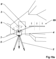
- the invention relates to a measurement system for optical measurement and for displaying an environment, with a laser scanner for recording measurement data, a processing unit for processing parts of the measurement data into processed measurement data and a display for displaying parts of the processed measurement data, which at least a portion of the represent environment; wherein the laser scanner comprises an optical distance measuring device for recording distance measuring data, with a transmitting unit for emitting a distance measuring radiation and a receiving unit for receiving returning parts of the distance measuring radiation, a flat sensor for detecting surface sensor data, in particular at least one color camera for recording image data, an optical axis of the sensor and a viewing direction of the sensor along the optical axis being defined by the sensor, a base, a support, which can be rotated about a support rotation axis, in particular a slow rotation axis is attached to the base, a beam steering unit for the distance measuring radiation, which is rotatably attached to the support about a beam rotation axis substantially orthogonal to the support rotation axis, in particular a fast rotation axis,
- One aspect of the invention relates, for example, to the fact that the processing unit is arranged on a computing device, in particular a computer or tablet, that is separate from the laser scanner, and the laser scanner and the computing device are configured in such a way that the measurement data is transferred from the laser scanner to the computing device, in particular wirelessly, in particular by means of a WLAN or Bluetooth connection, the transmission of the measurement data takes place during the measurement process, by means of data streaming of parts of the measurement data that is started simultaneously or at least promptly with respect to the start of the measurement process, at least initial processing of the parts of the measurement data with regard to a link the area sensor data with the distance measurement data and the first and second angle data takes place during the measuring process, and the representation of parts of the processed measurement data takes place during the measuring process and is continuously, in particular continuously, updated, in particular supplemented and/or renewed, based on the processed measurement data, in Specially, a display coupled or integrated with the computing device is provided for the display.
- a further embodiment relates to the fact that the laser scanner and the computing device are configured in such a way that control signals can be transmitted to the laser scanner by means of a monitoring and control unit on the computing device, in particular wirelessly, in particular by means of a WLAN or Bluetooth connection.
- a further embodiment relates to the computing device being equipped with an inertial measuring system and/or inclination sensors, so that based on a position of the computing device, in particular a position and/or orientation, an adjustment of a rotational position of the support about the support rotation axis and/or a Adjustment of a rotational position of the beam steering unit about the beam axis of rotation takes place, in particular essentially synchronously with a change in position of the computing device, in particular wherein at least one area of interest of the environment can be defined by adjusting at least a first position of the computing device, in particular wherein settings are defined for the at least one area of interest for the acquisition of measurement data and/or defined settings for the representation of parts of the processed measurement data can be made, in particular wherein the defined setting for the acquisition of measurement data is a measurement resolution of the area sensor and/or a measurement accuracy of the distance measuring device and/or a scanning resolution the distance measuring device, and/or the defined setting for the display of parts of the processed measurement data includes a display resolution and/or
- a further embodiment relates to the computing device being configured in such a way that auxiliary data can be accessed for processing the measurement data and/or for displaying parts of the processed measurement data, in particular wherein the auxiliary data is used for visualization in the form of an augmented reality and /or can be used in the form of a virtual reality.
- a further embodiment relates to the laser scanner comprising a position determination unit for providing referencing data, in particular position and/or orientation of the laser scanner, with at least one element of the following group: an inertial measuring system, an inclination sensor for detecting at least one inclination relative to the direction of gravity , a receiver for a global satellite navigation system and/or for a pseudo-satellite navigation system, a compass, in particular an electronic compass, and a barometer, the measurement data including the referencing data, and/or the data processing using a method for simultaneous Localization and mapping (SLAM) based.
- SLAM simultaneous Localization and mapping
- a laser scanner for the optical measurement of an environment comprising an optical distance measuring device for recording distance measurement data, with a transmitting unit for emitting a distance measuring radiation and a receiving unit for receiving returning ones Sharing the distance measuring radiation, a flat sensor for recording surface sensor data, in particular at least one color camera for recording image data, an optical axis of the sensor and a viewing direction of the sensor along the optical axis being defined by the sensor, a base, a support, which is rotatably mounted on the base about a support rotation axis, in particular a slow rotation axis, a beam steering unit for the distance measuring radiation, which essentially rotates about a support rotation axis orthogonal beam rotation axis, in particular a fast rotation axis, is rotatably attached to the support, a first angle encoder for detecting first angle data relating to a rotation of the support about the support rotation axis, and a second angle encoder for detecting
- a further embodiment relates to the fact that at least initial processing of parts of the measurement data takes place during the measurement process, in particular a linking of the scanning measurement data and the surface sensor data, in particular wherein the representation of parts of the processed measurement data takes place during the measurement process and continuously, in particular continuously , is updated based on the processed measurement data, in particular supplemented and / or renewed, in particular a display coupled or integrated with the laser scanner is provided for the display.
- a further embodiment relates to the fact that at least one area of interest of the environment can be defined based on the area sensor data, in particular with defined settings for the acquisition of measurement data and/or defined settings for the representation of parts of the processed measurement data being made for the at least one area of interest can.
- a further embodiment refers to the fact that, as part of the measuring process, all area sensor data required for the measuring process is first completely recorded before the acquisition of scanning measurement data begins, in particular whereby a 2D panoramic representation of at least a partial area of the environment is generated based on the recorded area sensor data or a 2D full dome representation is generated.
- a measurement system for optically measuring an environment with a laser scanner for recording measurement data, a processing unit for processing parts of the measurement data into processed measurement data, and a display unit for a defined representation of parts of the processed measurement data, which represent at least a partial area of the environment
- the laser scanner comprising an optical distance measuring device for recording distance measurement data, with a transmitting unit for emitting a distance measuring radiation and a receiving unit for receiving returning parts of the distance measuring radiation, a support , a beam steering unit for the distance measuring radiation, which is rotatably attached to the support about a beam rotation axis, in particular a fast rotation axis, an angle encoder for recording angle data relating to a rotation of the beam steering unit about the beam rotation axis, the measurement data comprising the distance measurement data and the angle data.
- the aspect of the invention is characterized in that a central reference point of the laser scanner is defined as the origin for distance and angle measurement, in particular by the intersection of the beam axis of rotation with a support axis of rotation for rotation of the support about a base, on the support
- An infrared sensor sensitive to the infrared wavelength range is arranged integrated, with the infrared sensor defining an optical axis of the infrared sensor and a viewing direction of the infrared sensor along the optical axis, and a position of the infrared sensor and an orientation of its optical Axis with respect to the beam steering unit and the central reference point is known
- the measurement data includes infrared data recorded with the infrared sensor, and the measurement data is linked to the infrared data, in particular so that temperature information is taken into account for the representation of parts of the processed measurement data.
- One embodiment refers to the fact that the representation of parts of the processed measurement data is generated in the form of a colored 3D point cloud and the temperature information is stored in the 3D point cloud and/or is displayed with a defined color coding.
- a laser scanner for the optical measurement of an environment comprising an optical distance measuring device for recording distance measurement data, with a transmitting unit for emitting a distance measuring radiation and a receiving unit for receiving returning ones Sharing the distance measuring radiation, a support, a beam steering unit for the distance measuring radiation, which is rotatably attached to the support about a beam rotation axis, in particular a fast rotation axis, and an angle encoder for recording angle data relating to a rotation of the beam steering unit about the beam rotation axis, wherein the distance measurement data and the angle data, hereinafter referred to as measurement data, are recorded as part of a measurement process which includes a scanning scan by means of the distance measuring device with a defined continuous, in particular continuous rotation of the beam steering unit about the beam rotation axis, and a continuous emission of the distance measuring radiation and a continuously receiving returning parts of the distance measuring radiation.
- One embodiment refers, for example, to the fact that the set of defined measurement programs and/or actions of the laser scanner includes activating the laser scanner, as well as at least one element of the following group: deactivating the laser scanner, starting the measuring process, interrupting the measuring process, aborting the measuring process, and restart the measurement process; in particular, wherein a set of different settings for the measuring process is stored and/or can be defined and the set of defined measuring programs and/or actions of the laser scanner further comprises at least one element of the following group: setting a setting from the set of settings for the measuring process, Starting the measurement process with a setting from the set of settings for the measurement process, and restoring a standard setting of the laser scanner, in particular a standard start configuration of the laser scanner.
- a further embodiment refers, for example, to the fact that the coded sequence of state changes of the control element is defined by a defined number of state changes during a defined time interval between the active and inactive states, and / or the coded sequence of external effects lasting over time is defined by one or more different ones Defined periods of time for maintaining the external effect are defined.
- a laser scanner for the optical measurement of an environment comprising an optical distance measuring device for recording distance measurement data, with a transmitting unit for emitting a distance measuring radiation and a receiving unit for receiving returning ones Sharing the distance measuring radiation, a flat sensor for recording surface sensor data, in particular at least one color camera for recording image data, an optical axis of the sensor and a viewing direction of the sensor along the optical axis being defined by the sensor, a support, a beam steering unit for the distance measuring radiation, which is rotatably attached to the support about a beam rotation axis, in particular a fast rotation axis, an angle encoder for detecting angle data relating to a rotation of the beam steering unit about the beam rotation axis, wherein the distance measurement data, the area sensor data and the angle data, below Called measurement data, are recorded as part of a measurement process, which includes a scanning scan by means of the distance measuring device with a defined continuous, in particular continuous rotation of the
- a central reference point of the laser scanner is defined as the origin for distance and angle measurement, in particular by the intersection of the beam axis of rotation with a support axis of rotation for a rotation of the support about a base
- the flat sensor is fixed is arranged on the support with a field of vision that is fixed relative to the support and looks away from the support, insofar as the field of view of the sensor only changes during the measurement process when the support moves, in particular when the support rotates about the beam axis of rotation, and a fictitious rearward extension of the optical axis of the flat sensor runs through the central reference point.
- One embodiment refers, for example, to the fact that a plurality of flat sensors are arranged on the support, with the fictitious rearward extension of its optical axis essentially running through the central reference point for each of the plurality of flat sensors.
- a further embodiment refers, for example, to the fact that a scanning plane of the distance measuring radiation is defined by a fictitious 360 degree rotation of the beam steering unit around the beam rotation axis, and one of the plurality of flat sensors is arranged such that its field of view cone intersects the scanning plane, in particular wherein the support is rotatably mounted on a base about a support axis of rotation, in particular a slow axis of rotation, and the field of view cone of the flat sensor with the steepest elevational orientation of the optical axis intersects with a fictitious extension of the support axis of rotation.
- a further embodiment relates, for example, to the fact that the support is rotatably mounted on a base about a support rotation axis, in particular a slow rotation axis, and the laser scanner has a further angle encoder for recording further angle data as measurement data relating to a rotation of the support about the support.
- Axis of rotation includes, the measuring process further includes multiple readings of the plurality of flat sensors with respect to different azimuthal viewing directions of the individual sensors, and the plurality of flat sensors are arranged in such a way that they enable a full dome measurement as part of the measuring process, in particular wherein the field of view cone of the flat Sensor with the steepest elevational alignment of the optical axis intersects with a fictitious extension of the support rotation axis, with a minimum detection radius for the whole dome measurement being defined by the plurality of flat sensors in such a way that a spherical surface with the central one is formed by the central reference point and the minimum detection radius reference point is defined in the center, and as part of the measuring process, at least one hemispherical surface defined by the spherical surface can just be scanned by the plurality of flat sensors, in particular wherein a partial area of the sphere that is larger than can be scanned by the plurality of flat sensors the hemispherical surface.
- a laser scanner for optically measuring an environment, comprising an optical distance measuring device for recording distance measurement data, with a Transmitting unit for emitting a distance measuring radiation and a receiving unit for receiving returning parts of the distance measuring radiation, a flat sensor for detecting surface sensor data, in particular at least one color camera for recording image data, with an optical axis of the sensor and a viewing direction of the sensor along through the sensor the optical axis is defined, a support, a beam steering unit for the distance measuring radiation, which is rotatably attached to the support about a beam rotation axis, in particular a fast rotation axis, an angle encoder for recording angle data relating to a rotation of the beam steering unit about the beam rotation axis , wherein the distance measurement data, the area sensor data and the angle data, hereinafter referred to as measurement data, are recorded as part of a measuring process, which includes a scanning scan by means of the distance measuring device with a defined continuous,
- a central reference point of the laser scanner is defined as the origin for distance and angle measurement, in particular by the intersection of the beam axis of rotation with a support axis of rotation for rotation of the support about a base
- a plurality of flat Sensors with different elevational alignment of the optical axes are fixedly arranged on the support, insofar as the fields of view of the sensors only change during the measurement process when the support moves, in particular when the support rotates about the beam axis of rotation, and in each case for For each of the multitude of flat sensors, the fictitious rearward extension of its optical axis essentially runs through the central reference point.
- One embodiment refers, for example, to the fact that the plurality of flat sensors are arranged with the same azimuthal direction, in particular wherein a scanning plane of the distance measuring radiation is defined by a fictitious 360 degree rotation of the beam steering unit about the beam rotation axis and the optical axes of the plurality of flat sensors are arranged in a plane outside the scanning plane.
- a further embodiment refers, for example, to the fact that the field of view cone of the flat sensor with the steepest elevational alignment of the optical axis intersects with the scanning plane at a distance of between 0.25 and 7m from the central reference point.
- a laser scanner for the optical measurement of an environment comprising an optical distance measuring device for recording distance measurement data, with a transmitting unit for emitting a distance measuring radiation and a receiving unit for receiving returning ones Sharing the distance measuring radiation, a flat sensor for recording surface sensor data, in particular at least one color camera for recording image data, an optical axis of the sensor and a viewing direction of the sensor along the optical axis being defined by the sensor, a support, a beam steering unit for the Distance measuring radiation, which is rotatably attached to the support about a beam rotation axis, in particular a fast rotation axis, an angle encoder for detecting angle data relating to a rotation of the beam steering unit about the beam rotation axis, wherein the distance measurement data, the area sensor data and the angle data, hereinafter measurement data called, are recorded as part of a measuring process, which includes a scanning scan by means of the distance measuring device with a defined continuous, in particular continuous rotation of
- the aspect of the invention is characterized in that the laser scanner comprises a luminaire illuminating the field of view of the area sensor, in particular one or more LEDs, with the luminaire defining an optical axis of the luminaire and an illumination direction of the luminaire along the optical axis of the luminaire, and the lamp is used for specifically controllable illumination that is essentially directed towards the field of view of the flat sensor.
- One embodiment refers, for example, to the fact that the flat sensor is arranged on the support and the lamp is arranged directly next to the flat sensor on the support, in particular with a maximum lateral offset between the optical axis of the lamp and the optical axis of the flat sensor 4cm.
- a further embodiment refers, for example, to the fact that the lamp emits essentially white light, that is, broadband light in the visible wavelength range, in particular in that the lamp is designed as a dual LED, namely as a pair of LEDs with two individual ones that differ in terms of their emitted spectral range LEDs.
- a further embodiment relates, for example, to the fact that a plurality of flat sensors are arranged on the support, with each of the plurality of flat sensors being assigned lights that can be specifically controlled for this sensor and essentially illuminate the field of vision of this sensor.
- a further embodiment relates, for example, to the fact that a first set of area sensor data is acquired, in particular area sensor data with reduced resolution, a set of lighting settings for the luminaire is derived based on the first set of area sensor data, and a second set is derived based on the set of lighting settings of area sensor data is recorded, in particular wherein the first set of area sensor data is recorded without using the luminaire or using uniform lighting by the luminaire.
- a laser scanner for the optical measurement of an environment comprising an optical distance measuring device for recording distance measurement data, with a transmitting unit for emitting a distance measuring radiation and a receiving unit for receiving returning ones Sharing the distance measuring radiation, a base, a support, which is rotatably attached to the base about a support rotation axis, in particular a slow rotation axis, a beam steering unit for the distance measuring radiation, which is rotatably attached to the support about a beam rotation axis essentially orthogonal to the support rotation axis, in particular a fast rotation axis, a first angle encoder for detecting first angle data relating to a rotation of the support about the support rotation axis, and a second angle encoder for detecting second angle data relating to a rotation of the beam steering unit about the beam rotation axis, wherein the distance measurement data and the first and second angle data, hereinafter Called measurement data, are recorded as part of a
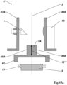
- the aspect of the invention is characterized in that the base exclusively comprises an overall effective stabilization area axially along the support axis of rotation, by means of which stabilization of the support with respect to a tilting of the support relative to the base is achieved, the stabilization area has a first extension axially along the support axis of rotation and has a second extent perpendicular to the support axis of rotation and essentially radially symmetrical with respect to the support axis of rotation, and the second extent is larger than the first extent.
- One embodiment refers to the fact that the support is rotatably mounted relative to the base by a single bearing ring about the support axis of rotation, with the stabilization being achieved exclusively by the single bearing ring.
- a further embodiment refers, for example, to the fact that the bearing ring is designed as a single-row four-point roller bearing, or the bearing ring is designed as a single-row plain bearing with an outer and inner ring and the outer ring and the inner ring have two contact races that are axially spaced with respect to the support axis of rotation, in particular two running lines or two running surfaces.
- a further embodiment refers, for example, to the fact that the stabilization is generated on the bearing ring by means of a preload acting radially to the support axis of rotation.
- a further embodiment refers, for example, to the fact that the second extent is at least a factor of two larger than the first extent, in particular where the second extent is at least a factor of five larger than the first extent, in particular where the second extent is at least one A factor of ten is larger than the first dimension.
- a further embodiment relates, for example, to the fact that a lubricant-repellent emulsion is applied along a boundary region essentially parallel to a contact run, so that a spread of a lubricant for the bearing ring is limited by the surface tension of the lubricant-repellent emulsion essentially through the boundary region, or the Bearing ring is designed as a four-point rolling bearing in the form of a dry running ring bearing with ceramic rolling elements.
- a laser scanner for the optical measurement of an environment comprising an optical distance measuring device for recording distance measurement data, with a transmitting unit for emitting a distance measuring radiation and a receiving unit for receiving returning parts of the distance measuring radiation, a base, a support, which is rotatably attached to the base about a support rotation axis, in particular a slow rotation axis, a beam steering unit for the distance measurement radiation, which is about a beam rotation axis essentially orthogonal to the support rotation axis, in particular a fast rotation axis, rotatably attached to the support, a first angle encoder for detecting first angle data regarding a rotation of the support about the support rotation axis, and a second angle encoder for detecting second angle data regarding a rotation of the beam steering unit about the beam rotation axis , wherein the distance measurement data and the first and second angle data, hereinafter referred to as measurement data, are recorded as part of
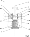
- the aspect of the invention is characterized in that the base is designed exclusively as a passive element with respect to a rotation of the support about the support axis of rotation, to the extent that all active electronics required for motorizing the rotation about the support axis of rotation are exclusively in the support is arranged and rotates with the support about the support axis of rotation, in particular the following components are arranged as a whole in the support and rotate with the support about the support axis of rotation: an active drive element for the rotation of the support about the support axis of rotation, in particular a rotary motor with a drive shaft coupled to the motor or an electrical coil element for a radial interaction with respect to the support axis of rotation between the electrical coil element and a passive magnetic element in the base, and a power supply unit for the active drive element.
- a rotary motor arranged in the support is designed with a drive shaft coupled to the motor, the drive shaft with an offset to the support axis of rotation axially substantially parallel to the support Axis of rotation runs, the base comprises a running surface that is circularly symmetrical about the support axis of rotation, an impeller is arranged on the drive shaft, in particular with a rubber ring, which is in operative connection with the running surface in such a way that when the drive shaft rotates, the impeller runs along the running surface and moves with it the support rotates relative to the base about the support axis of rotation, in particular wherein the tread defines a fictitious circle and the impeller is arranged within the circle.
- a further embodiment refers, for example, to the fact that the following components are arranged as a whole in the support and are operated by means of the energy supply unit: the optical distance measuring device, the flat sensor, a monitoring and control unit, and electronics of the first and second angle encoders, in particular wherein the base and the support are designed such that no electrical power transmission and no electrical signal transmission takes place between the base and the support during the measurement process.
- a further embodiment refers, for example, to the fact that the laser scanner comprises only one energy supply unit overall, namely the energy supply unit for the active drive element, which is arranged in the support, in particular wherein the base is permanently and insurmountably electrically decoupled from the support, so that no electrical power transmission between the support and the base.
- a further embodiment relates, for example, to the laser scanner comprising a wireless signal transmission unit, in particular based on a WLAN or Bluetooth connection, the signal transmission unit being arranged as a whole in the support, with a two-way exchange between the laser scanner and an external control unit Control signals are provided and/or a transfer of part of the measurement data from the laser scanner to an external computing and/or storage unit is provided, in particular wherein a bilateral transmission of measurement data and/or auxiliary data between the laser scanner and the external computing and/or storage unit is provided is.
- a further embodiment refers, for example, to the fact that the transmission of the measurement and/or auxiliary data takes place essentially parallel to the measurement process by means of data streaming of parts of the measurement data that is started simultaneously or at least in a timely manner with respect to the start of the measurement process.
- a laser scanner for the optical measurement of an environment comprising an optical distance measuring device for recording distance measurement data, with a transmitting unit for emitting a distance measuring radiation and a receiving unit for receiving returning parts of the distance measuring radiation, a base, a support, which is rotatably attached to the base about a support rotation axis, in particular a slow rotation axis, a beam steering unit for the distance measurement radiation, which is about a beam rotation axis essentially orthogonal to the support rotation axis, in particular a fast rotation axis, rotatably attached to the support, a first angle encoder for detecting first angle data regarding a rotation of the support about the support rotation axis, and a second angle encoder for detecting second angle data regarding a rotation of the beam steering unit about the beam rotation axis , wherein the distance measurement data and the first and second angle data, hereinafter referred to as measurement data, are recorded as part of
- the aspect of the invention is characterized in that for the rotation of the support about the support rotation axis, a rotary motor arranged in the support with a coupled to the motor Drive shaft is formed, the drive shaft runs axially substantially parallel to the support axis of rotation with an offset to the support axis of rotation, the base comprises a running surface which is circularly symmetrical about the support axis of rotation, an impeller is arranged on the drive shaft, in particular with a rubber ring, which is connected in this way the running surface is operatively connected so that when the drive shaft rotates, the impeller runs along the running surface and the support thus rotates relative to the base about the support axis of rotation, in particular where the running surface defines a fictitious circle and the running wheel is arranged within the circle.
- a laser scanner for the optical measurement of an environment comprising an optical distance measuring device for recording distance measurement data, with a transmitting unit for emitting a distance measuring radiation and a receiving unit for receiving returning parts of the distance measuring radiation, a support, a beam steering unit for the distance measuring radiation, which is rotatably attached to the support about a beam rotation axis, in particular a fast rotation axis, and an angle encoder for recording angle data relating to a rotation of the beam steering unit about the beam rotation axis .
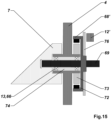
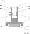
- the aspect of the invention is characterized in that the beam steering unit is connected to a shaft mounted in the support along the beam axis of rotation, in particular wherein the shaft penetrates into the beam steering unit with a defined penetration depth or is formed in one piece with the beam steering unit on the shaft
- Bell element is arranged, in particular wherein the bell element is fixedly attached to the shaft or is formed in one piece with the shaft, a bell belly and a bell back being defined by the bell element, passive magnetic elements of a drive for rotating the shaft being arranged in the bell belly, anchored in the support active drive elements of the drive are arranged to generate an electro-magnetic interaction with the passive magnetic elements, in particular electrical coil elements, the active drive elements protruding at least partially into the bell belly, and the shaft and thus the beam steering unit through a radial interaction between the active drive elements and the Passive magnetic elements experience a defined rotational movement around the beam axis of rotation.
- One embodiment refers to the fact that the active drive elements sink completely into the bell belly.
- a further embodiment refers, for example, to the fact that at least one ring of the bearing for supporting the shaft in the support protrudes into the bell belly.
- a further embodiment refers, for example, to the fact that the ring of the bearing that projects into the bell belly is designed as a rolling bearing ring and that rolling elements of the rolling bearing ring protrude at least partially into the bell belly.
- a further embodiment relates, for example, to the fact that at least one ring of the bearing for mounting the shaft in the support projects into the beam steering unit, in particular wherein the ring projecting into the beam steering unit is designed as a rolling bearing ring and rolling elements of the rolling bearing ring at least partially protrude into the jet steering unit.
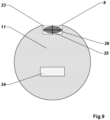
- a further embodiment relates, for example, to the fact that the shaft exclusively comprises a single effective stabilization region axially along the beam rotation axis, by means of which the shaft is stabilized with respect to a tilting of the shaft towards the support, the beam steering unit, the bell element and the shaft being such are designed and arranged with respect to one another so that their common center of gravity lies axially along the beam axis of rotation in the stabilization area, in particular wherein the stabilization is achieved exclusively by a bearing for supporting the shaft in the support, which encompasses the center of gravity in a substantially axially symmetrical manner.
- a further embodiment refers, for example, to the fact that a coding element for the angle encoder is arranged on the back of the bell, in particular wherein the coding element is formed in one piece with the bell element.
- a further embodiment refers, for example, to the fact that at least one of the following connections takes place exclusively by means of gluing and/or pressing: a connection of the shaft to the stabilization element, a connection of the shaft to the bell element, a connection of the passive magnetic element to the bell element, and a connection of the coding element to the bell element.
- a laser scanner for the optical measurement of an environment comprising an optical distance measuring device for recording distance measurement data, with a transmitting unit for emitting a distance measuring radiation and a receiving unit for receiving returning parts of the distance measuring radiation, a support, a beam steering unit for the distance measuring radiation, which is rotatably attached to the support about a beam rotation axis, in particular a fast rotation axis, and an angle encoder for recording angle data relating to a rotation of the beam steering unit about the beam rotation axis .
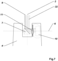
- the aspect of the invention is characterized in that the beam steering unit is mounted in the support via a shaft axially along the beam axis of rotation, the beam steering unit comprising a mirror surface for deflection of the distance measuring radiation, in particular a plane tilted by 45 ° with respect to the beam axis of rotation or a tilted parabolic mirror surface, the shaft has a penetration area at one end, the beam steering unit has a surrounding area for surrounding the penetration area of the shaft as part of a coupling of the beam steering unit with the shaft, the surrounding area has a shape that is suitable for the shaft in Frame of the coupling over a length of the penetration area in such a way that in the coupled state between the shaft and the surrounding area of the beam steering unit there is a gap with a defined width, the surrounding area has a stabilization element that can be pressed into the gap for tolerance compensation and for the stable connection of the beam steering unit the shaft, the stabilization element in an uncoupled state has a thickness that is greater than the width of the gap, and the beam steering
- One embodiment refers to the fact that the stabilization element and the shaft are glued to one another as part of the coupling.
- a further embodiment relates, for example, to the fact that the surrounding area comprises at least two stabilization elements spaced apart in the axial direction with respect to the beam axis of rotation.
- a further embodiment refers, for example, to the fact that the stabilization element is annular.
- a further embodiment refers, for example, to the fact that the stabilization element consists of a material with homogeneous plastic properties, in particular with a homogeneous plastic flow region.
- a further embodiment relates, for example, to the fact that the stabilization element is integrated into the beam steering unit, in particular wherein the stabilization element is molded onto the beam steering unit or the beam steering unit and the stabilization element are formed in one piece.
- a further embodiment refers, for example, to the fact that the defined tolerance range for an effect of the residual elastic forces on the mirror surface is selected such that a surface accuracy of the mirror surface of plus/minus 5 ⁇ m, in particular of plus/minus 3 ⁇ m, in particular of plus/minus 1 ⁇ m or of plus/minus 300 nm with respect to a defined ideal design for the mirror surface.
- a laser scanner for the optical measurement of an environment comprising an optical distance measuring device for recording distance measurement data, with a transmitting unit for emitting a distance measuring radiation and a receiving unit for receiving parts of the distance measuring radiation returning from the environment, a support, a beam steering unit for the distance measuring radiation, which is rotatably attached to the support about a beam rotation axis, in particular a fast rotation axis, the beam steering unit comprising a mirror surface for deflecting the distance measuring radiation, in particular a a flat mirror surface tilted with respect to the beam axis of rotation or a parabolic mirror surface, and an angle encoder for recording angle data relating to a rotation of the beam steering unit about the beam axis of rotation, the distance measurement data and the angle data, hereinafter referred to as measurement data, being recorded as part of a measuring process, which a scanning scan by means of the distance measuring device includes a defined continuous, in particular continuous Rotation
- the aspect of the invention is characterized in that receiving optics for parts of the distance measuring radiation returning via the mirror surface are arranged on the support, in particular wherein the optical axis of the receiving optics is rectified, in particular coaxial, to the beam rotation axis, an exit area for the emission of the Distance measuring radiation is arranged in the direction of the mirror surface on the support and the exit area has a lateral offset with respect to the optical axis of the receiving optics and the distance measuring radiation emitted through the exit area is emitted onto the mirror surface parallel to the optical axis of the receiving optics.
- One embodiment refers, for example, to the fact that the receiving optics have a recess or a window, in particular a flat glass window, into which the exit area lies or which forms the exit area.
- a further embodiment relates, for example, to the fact that the exit area is arranged next to the receiving optics, in particular immediately adjacent to the receiving optics.
- a further embodiment refers, for example, to the fact that the exit region is designed in such a way that the geometry and orientation of the exit region essentially covers the maximum beam diameter of the outgoing distance measuring radiation at the exit region, in particular wherein the geometry and orientation of the exit region essentially covers the Geometry and orientation of the beam waist (the beam cross section) corresponds to the outgoing distance measuring radiation at the exit area.
- a further embodiment relates, for example, to the fact that the transmitting unit comprises a laser diode for generating the distance measuring radiation as laser radiation and the beam cross section of the outgoing distance measuring radiation at the level of the exit region has an oval shape, in particular elliptical shape, in particular with a short semi-axis aligned in the direction of the lateral offset.
- a further embodiment relates, for example, to the fact that the receiving optics further comprises a correction optics for taking into account a parallax effect caused by the lateral offset of the exit region to the beam rotation axis for parts of the distance measuring beams returning from a distance shorter than a defined near field distance, in particular where the correction optics as cylindrical lens is formed.
- a further embodiment relates, for example, to the fact that a compensation algorithm is provided in order to determine compensation parameters that are dependent on the angle data for a parallax effect with respect to the outgoing and caused by the continuous rotation of the beam steering unit about the beam rotation axis and by the lateral offset of the exit region to the beam rotation axis to compensate for returning parts of the distance measuring radiation, in particular where the compensation parameters are in
- the framework of referencing the measurement data with respect to a common coordinate system must be taken into account.
- a further embodiment refers, for example, to the fact that the exit area and the compensation algorithm are designed in such a way that, within the framework of a defined measurement tolerance for referencing the measurement data with respect to the common coordinate system for compensating for the parallax effect, in addition to the compensation algorithm, no further adjustment of the laser scanner is required.
- a further embodiment refers, for example, to the fact that the exit area and the receiving optics are arranged in such a way that there is a lateral offset of at least 0.5 cm between a fictitious extension of the optical axis of the receiving optics and a central propagation axis of the distance measuring radiation at the level where the distance measuring radiation hits the beam steering unit is present.
- a further embodiment refers, for example, to the fact that the transmitting unit and the receiving unit are arranged on a common circuit board.
- a further aspect of the invention taken alone or in combination with the aspects of the invention already mentioned, relates to an electronic laser distance measuring module for a distance measurement to a target object, in particular for use in a laser scanner, wherein the laser distance measuring module comprises a transmission unit for generating transmission signals, in particular wherein the transmission signals are generated by pulsed laser measuring radiation, a reception unit for receiving parts of the transmission signals returning from the target object as reception signals, a reception circuit for conditioning and digitizing the reception signals, so that ultimately a distance to the target object can be derived based on the signal transit time method, and a control for the transmission unit and the receiving circuit.
- the laser distance measuring module comprises a transmission unit for generating transmission signals, in particular wherein the transmission signals are generated by pulsed laser measuring radiation, a reception unit for receiving parts of the transmission signals returning from the target object as reception signals, a reception circuit for conditioning and digitizing the reception signals, so that ultimately a distance to the target object can be derived based on the signal transit time method, and a control for the transmission unit and the receiving
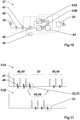
- the receiving circuit comprises a comparator stage for deriving a signal strength of a received signal, an amplifier stage for adjusting a signal strength, in particular by amplifying or attenuating an input signal, a first and a second analog-digital conversion stage, wherein the receiving circuit and the transmitting unit can be controlled by the controller in such a way that a continuous sequence of distance measurements using alternating use of the first and second analog-digital conversion stages includes a first distance measurement by means of the first analog-digital conversion stage, in particular based on a first signal packet of successive received signals , second distance measurement by means of the second analog-digital conversion stage, in particular based on a second signal packet of successive received signals, use of a first received signal as a test signal, use of a second received signal as a measurement signal, supply of the test signal to the comparator stage and derivation of a signal strength of the test signal by the Comparator stage, setting of the amplifier stage for at least parts of the received signals containing the measurement signal
- the receiving circuit further comprises an activation unit, by means of which a first setting is carried out, the test signal being taken into account for the derivation of the distance to the target object, and a second setting is carried out, the test signal being used for the derivation of the distance to the target object Target object is rejected, in particular wherein a value range for a usable signal strength of the sample signal is defined, the signal strength of the sample signal derived by the comparator stage is compared with the value range, and the activation unit is activated based on the comparison of the signal strength with the value range, that if the signal strength of the test signal is within the value range, the test signal is taken into account for deriving the distance to the target object, and if the signal strength of the test signal is outside the value range, the test signal is discarded for deriving the distance to the target object.
- an activation unit by means of which a first setting is carried out, the test signal being taken into account for the derivation of the distance to the target object, and a second setting is carried out, the
- a further embodiment refers, for example, to the fact that the setting of the amplifier unit and the derivation of the distance to the target object in the context of a single distance measurement is based on a signal packet consisting of a maximum of three consecutive received signals.
- a further embodiment refers, for example, to the fact that a received signal of an immediately preceding distance measurement from the plurality of distance measurements is used as a current test signal for a current distance measurement from the plurality of distance measurements, in particular with the last received signal of the immediately preceding distance measurement being used as the current test signal is used.
- a further aspect of the invention taken alone or in combination with the aspects of the invention already mentioned, relates to an electronic laser distance measuring module for a distance measurement to a target object, in particular for use in a laser scanner, the laser distance measuring module comprising a transmitting unit for generating transmission signals, wherein the Transmission signals are generated by pulsed laser measuring radiation, a reception unit for receiving parts of the transmission signals returning from the target object as reception signals, a reception circuit for conditioning and digitizing the reception signals, so that ultimately a distance to the target object can be derived based on the signal transit time method, and a control for the transmission unit and the receiving circuit.
- the aspect of the invention is characterized in that the receiving circuit comprises several, and at least a first and a second, analog-digital conversion stages, the controller being configured to control the receiving circuit and the transmitting unit in such a way that a continuous sequence of distance measurements is included an alternating, staggered and mutually alternating, use of the multiple analog-digital conversion stages for one distance measurement each, each analog-digital conversion stage of the multiple analog-digital conversion stages per distance measurement having a self-contained sampling phase for sampling an incoming Signal, in particular a pulse packet, and then a self-contained output phase for outputting during the sampling phase sampled values, wherein within the scope of the alternating use, the respective output phases of the first analog-digital conversion stage are temporally in the respective sampling phases of at least the second analog-digital conversion stage, and the respective output phases of the second analog-digital conversion stage are temporally in the respective sampling phase of the first or another one of the several analog-digital conversion stages.
- a laser scanner for the optical measurement of an environment comprising an optical distance measuring device for recording distance measurement data with one of the laser distance measurement modules described above, a support, a beam steering unit for the Distance measuring radiation, which is rotatably attached to the support about a beam rotation axis, in particular a fast rotation axis, and an angle encoder for recording angle data relating to a rotation of the beam steering unit about the beam rotation axis, the distance measurement data and the angle data, hereinafter referred to as measurement data, be recorded as part of a measuring process, which includes a scanning scan by means of the distance measuring device with a defined continuous, in particular continuous rotation of the beam steering unit about the beam rotation axis, and a continuous emission of the distance measuring radiation and a continuous reception of returning parts of the distance measuring radiation.
- a laser scanner for the optical measurement of an environment comprising an optical distance measuring device for recording distance measurement data, with a transmitting unit for emitting a distance measuring radiation and a receiving unit for receiving returning parts of the distance measuring radiation, a base, a support, which is rotatably attached to the base about a support rotation axis, in particular a slow rotation axis, a beam steering unit for the distance measurement radiation, which is about a beam rotation axis essentially orthogonal to the support rotation axis, in particular a fast rotation axis, rotatably attached to the support, a first angle encoder for detecting first angle data regarding a rotation of the support about the support rotation axis, and a second angle encoder for detecting second angle data regarding a rotation of the beam steering unit about the beam rotation axis , wherein the distance measurement data and the first and second angle data, hereinafter referred to as measurement data, are recorded as part of
- the aspect of the invention is characterized in that the support has a skeletal structure consisting of at least two separately detachable support structures as skeleton parts, a first of the two support structures is rotatably mounted relative to the base, a second support structure is only coupled to the first support structure, in particular based on a connection using normal pins, the first support structure extends in the support rotation axis Building construction, by means of which a stable fastening of the second support structure with respect to a tilting of the second support structure to the support axis of rotation can be achieved, and the beam steering unit is mounted exclusively in and rotatable relative to the second support structure.
- One embodiment refers, for example, to the fact that the first support structure is based on an upside-down T-shape, namely where a circular disk connected to the base or an annular disk connected to the base forms the T-crossbar, and the building forms the T-longitudinal bar forms.
- a further embodiment relates, for example, to the fact that the support comprises a third support structure as a further skeleton part, which is separately releasably attached to the building of the first support structure, the second and third support structures are each essentially based on a plate shape with a flat side, and the building with two contact sides facing away from each other, a receptacle forms on the one hand for the flat side of the second support structure and on the other hand for the flat side of the third support structure.
- a further embodiment relates, for example, to the fact that the laser scanner comprises a flat sensor for recording surface sensor data, in particular at least one color camera for recording image data, with the sensor defining an optical axis of the sensor and a viewing direction of the sensor along the optical axis is, the distance measuring device is arranged in the second support structure, the flat sensor is arranged in the third support structure, and that the distance measuring device and / or the flat sensor is modularly interchangeable, in particular wherein the first or second or third or a further support structure is an energy supply unit for comprises the distance measuring device and/or the flat sensor.
- a laser scanner for the optical measurement of an environment comprising an optical distance measuring device for recording measurement data comprising distance measurement data, with a transmitting unit for emitting a distance measuring radiation and a receiving unit for Receiving returning parts of the distance measuring radiation, a base, a support, which is rotatably attached to the base about a support rotation axis, in particular a slow rotation axis, a beam steering unit for the distance measurement radiation, which rotates about a beam that is essentially orthogonal to the support rotation axis.
- Axis of rotation in particular a fast axis of rotation, is rotatably attached to the support, and a first angle encoder for detecting first angle data relating to a rotation of the support about the support axis of rotation, and a second angle encoder for detecting second angle data relating to a rotation of the beam steering unit about the Beam axis of rotation, wherein the distance measurement data, the area sensor data and the first and second angle data, hereinafter referred to as measurement data, are recorded as part of a measuring process which includes a scanning scan by means of the distance measuring device with a defined, continuous, in particular continuous, rotation of the support around the support -Axis of rotation, a defined continuous, in particular continuous rotation of the beam steering unit about the beam rotation axis, and a continuous emission of the distance measuring radiation and a continuous reception of returning parts of the distance measuring radiation.
- the aspect of the invention is characterized in that the laser scanner includes a status display for displaying a device status, in particular for displaying a status of the measuring process, the status display is arranged on the support, that is to say when the support rotates around the support Axis of rotation also rotates, the status display is designed in such a way that it looks essentially uniform in all azimuthal directions with respect to the support axis of rotation, so that regardless of a rotational position of the support about the support axis of rotation, the same is visible to a user of the laser scanner from all horizontal user perspectives Information provided in the status display is visible and readable.
- One embodiment refers, for example, to the fact that the status display is designed by means of individual lights, which are arranged - in particular directly - adjacent to the entire support at a substantially identical elevation.
- a further embodiment refers, for example, to the fact that the status display is designed by means of lighting means arranged continuously and without interruption, which essentially completely enclose the support and the support rotation axis, in particular where the lighting means are designed as an LED ring.
- a further embodiment refers, for example, to the fact that the status display is designed by means of a light guide ring with at least one coupling of light, in particular by means of two or four couplings, with increasing distance from the coupling position along the light guide ring, the quotient of radiation, namely the radial light Decoupling, to forward the light along the light guide ring, increases.
- a further embodiment relates, for example, to the fact that the status display is designed such that the device status is revealed to a user by means of visual coding, in particular by means of a defined color coding of the status display and/or by means of a defined flash coding of the status display.
- a laser scanner for the optical measurement of an environment comprising an optical distance measuring device for recording distance measurement data, with a transmitting unit for emitting a distance measuring radiation and a receiving unit for receiving returning parts of the distance measuring radiation, a flat sensor for recording surface sensor data, in particular at least one color camera for recording image data, an optical axis of the sensor and a viewing direction of the sensor along the optical axis being defined by the sensor, a support, a beam steering unit for the distance measuring radiation, which is rotatably attached to the support about a beam rotation axis, in particular a fast rotation axis, and an angle encoder for recording angle data relating to a rotation of the beam steering unit about the beam rotation axis.
- the aspect of the invention is characterized in that the support is formed by means of a skeletal structure, the support comprises a cover carried by the skeletal structure and detachable therefrom as a casing element, and the flat sensor is attached to the casing element and is carried by the casing element.
- the laser scanner comprises a plurality of flat sensors, which are each individually attached to the casing element and are individually carried by the casing element, to the extent that each flat sensor of the plurality of flat sensors is carried separately and individually by the casing element is, in particular wherein the casing element is designed with aperture openings for the flat sensors, the individual flat sensors of the plurality of flat sensors are attached to the inside of the casing element, and the individual flat sensors of the plurality of flat sensors each look through one of the aperture openings of the casing element .
- a laser scanner for the optical measurement of an environment comprising an optical distance measuring device for recording distance measurement data, with a transmitting unit for emitting a distance measuring radiation and a receiving unit for receiving returning parts of the distance measuring radiation, a base, a support, which is rotatably attached to the base about a support rotation axis, in particular a slow rotation axis, a beam steering unit for the distance measurement radiation, which is about a beam rotation axis essentially orthogonal to the support rotation axis, in particular a fast rotation axis, rotatably attached to the support, a first angle encoder for detecting first angle data regarding a rotation of the support about the support rotation axis, and a second angle encoder for detecting second angle data regarding a rotation of the beam steering unit about the beam rotation axis , wherein the distance measurement data and the first and second angle data, hereinafter referred to as measurement data, are recorded as part of
- the aspect of the invention is characterized in that the distance measuring device is designed in such a way that a measuring beam ensemble, formed from a plurality of individual distance measuring beams, is emitted, in particular wherein the measuring beam ensemble is transmitted as part of the measuring process via a common beam for the plurality of distance measuring beams Mirror surface of the beam steering unit is deflected.
- One embodiment refers, for example, to the fact that the maximum divergence between adjacent individual beams of the measuring beam ensemble is less than 15 degrees, in particular less than 1 degree.
- a further embodiment refers, for example, to the fact that the individual beams of the measuring beam ensemble are emitted from the support in the direction of the beam steering unit as beam fans, forming a line of individual beams, in particular wherein the line of individual beams is along a line perpendicular to the axis of rotation of the beam and perpendicular extends to the support axis of rotation, in particular where the beam fan consists of a maximum of ten individual beams.
- a laser scanner for the optical measurement of an environment comprising an optical distance measuring device for recording distance measurement data, with a transmitting unit for emitting a distance measuring radiation and a receiving unit for receiving returning parts of the distance measuring radiation, a support, a beam steering unit for the distance measuring radiation, which is rotatably attached to the support about a beam rotation axis, in particular a fast rotation axis, and an angle encoder for recording angle data relating to a rotation of the beam steering unit about the beam rotation axis , wherein the measurement data includes the distance measurement data and the angle data, which are recorded as part of a measurement process which includes a scanning scan by means of the distance measuring device with a defined continuous, in particular continuous rotation of the beam steering unit about the beam rotation axis, and a continuous emission of the distance measuring radiation and continuously receiving returning parts of the distance measuring radiation.
- the aspect of the invention is characterized by a receiving element for receiving the base, wherein the receiving element is detachable from the base by means of a latching device, and wherein the latching device on the base comprises an outlet into which a ring is embedded, which ring has a circumferential inside has a continuous cavity, and comprises a pin on the receiving element, the pin comprising at least three locking bodies, the locking bodies pushing out radially in a basic position of a release device in order to block the detachability of the receiving element from the base in that the locking bodies engage in the cavity, and the locking bodies are allowed to escape radially into the pin by actuating the release device in order to ensure that the receiving element can be detached from the base.
- One embodiment refers to the fact that the outlet is cylindrical.
- a further embodiment refers, for example, to the fact that the receiving element is a tripod head or is designed to be attached to a tripod head.
- a further embodiment relates, for example, to the fact that a locking body is designed as a body of revolution, in particular as a sphere or an ellipsoid, a trapezoid, a pyramid, a trapezoid with roundings, or a pyramid with roundings.
- a further embodiment refers, for example, to the fact that the locking bodies and the cavity are designed and coordinated with one another in such a way that the engagement of the locking bodies in the cavity results in a self-centering of the base, in particular a self-centering with respect to the support axis of rotation.
- a further embodiment relates, for example, to the fact that the release device is arranged in the pin and has at least one radial pin for actuating the release device, an axial pin for blocking or granting releasability, and a biasing spring for maintaining the basic position, the radial pin, the axial pin and the preload spring is in such an operative connection that in the basic position of the release device the axial pin Locking body pushes radially outwards, and when the release device is actuated, a displacement of the radial pin moves the axial pin against the biasing spring, and the axial pin releases space through its displacement and thus enables the locking body to escape radially into the pin.
- a further embodiment refers, for example, to the fact that the axial pin in the basic position presses the locking bodies into the cavity of the ring by means of a preload force from the preload spring.
- a further embodiment refers, for example, to the fact that each locking body has at least two contact points with the cavity, in particular has at least one contact line with the cavity.
- a further aspect of the invention in combination with the aspects of the invention already mentioned, relates to a laser scanner, wherein an axial position calibration process is provided for deriving axial position calibration parameters, which are taken into account in the context of referencing the measurement data in a common coordinate system, in particular the axial positions -Calibration process includes a measurement of an already known environment and / or known objects in the environment to be measured, in particular wherein the laser scanner for the axial position calibration process is arranged in a hollow test body with known spatial dimensions, and / or in a test environment and / or in A set of test objects with known positioning and/or dimensions relative to one another are attached to the environment intended as part of the effective measuring process and measured as part of the axial position calibration process.
- a further aspect of the invention in combination with the aspects of the invention already mentioned, relates to a laser scanner, wherein the beam steering unit, as part of the measuring process, rotates at a rotation speed of at least 50 Hz, in particular of at least 100 Hz, in particular of at least 250 Hz, in order to achieve the beam Axis of rotation rotates, and / or the base rotates around the support axis of rotation as part of the measuring process at a rotation speed of at least 0.01 Hz, in particular of at least 0.02 Hz, in particular of at least 0.03 Hz.
- a further aspect of the invention in combination with the aspects of the invention already mentioned, relates to a laser scanner, wherein within the scope of the measuring process, based on the rotation speed of the beam steering unit around the beam rotation axis and based on a pulse frequency of the distance measuring radiation, a minimum scanning point density of at least 3 points per 1° rotation angle.
- Figure 1 shows a typical laser scanner 1 according to the prior art, here with two axes of rotation, for example mounted on a tripod 2, the laser scanner 1 comprising a slow (vertical) axis of rotation - also called a support axis of rotation 3 - for an azimuthal rotation of the laser scanner 1, or a rotation of a support 4 of the laser scanner about a base 5 of the laser scanner 1 and a fast (horizontal) axis of rotation - also called the beam rotation axis 6 - with respect to a rapidly rotating beam deflection element 7, mounted in the support 4 of the laser scanner 1.
- a slow (vertical) axis of rotation - also called a support axis of rotation 3 - for an azimuthal rotation of the laser scanner 1
- a fast (horizontal) axis of rotation - also called the beam rotation axis 6 - with respect to a rapidly rotating beam deflection element 7, mounted in the support 4 of the laser scanner 1.
- a base or an azimuth axis of rotation is often dispensed with and instead the laser scanner is mounted on a means of transport, for example a ground or airborne carrier vehicle .
- a means of transport for example a ground or airborne carrier vehicle .
- Such laser scanners with only one beam rotation axis 6 are also called profilers.
- the laser scanner 1 here also has a camera 8, for example for recording RGB data, whereby the camera images of the environment can be linked to the scanning data generated by the rotating distance measuring beam 9 and associated angle encoder data for the direction of the distance measuring beam 9.
- the camera can in particular be individually movable, for example to capture different fields of view and/or to orient the camera images and the scanning data with respect to a common reference surface or a common coordinate system.
- Figure 2 shows typical main components of a common laser scanner 1', here for example with two axes of rotation, the laser scanner 1' being based on a structure using a base 5 and a support 4, the support 5 being rotatable about a support rotation axis 3, in particular a slow rotation axis stored on the base 5 13.
- the rotation of the support 4 about the support rotation axis 3 is often also called azimuthal rotation , regardless of whether the laser scanner 1 ', or the support rotation axis 3, are aligned exactly vertically.
- the core of the laser scanner 1 ' is an optical distance measuring device 10 arranged in the support 4 for recording distance measuring data, with a transmitting unit for emitting a distance measuring radiation 9, for example pulsed laser radiation, and a receiving unit with receiving optics, in particular a lens 11, and a light-sensitive sensor for receiving of returning parts of the distance measuring radiation 9, an echo being received from a backscattering surface point in the environment and, for example, a distance to the surface point being derived based on the transit time, the shape and/or the phase of the pulse.
- a transmitting unit for emitting a distance measuring radiation 9, for example pulsed laser radiation
- a receiving unit with receiving optics, in particular a lens 11, and a light-sensitive sensor for receiving of returning parts of the distance measuring radiation 9, an echo being received from a backscattering surface point in the environment and, for example, a distance to the surface point being derived based on the transit time, the shape and/or the phase of the pulse.
- the surroundings are scanned by varying the alignment of the emission direction of the distance measuring beam 9 by means of a rotating beam steering unit 7 for the distance measuring radiation, which is rotatably mounted 13 in the support 4 about a beam rotation axis 6 that is essentially orthogonal to the support rotation axis 3, in particular a fast rotation axis is.
- the emission direction of the Distance measuring beam 9 is recorded and linked to correspondingly recorded distance measuring data.
- the entire environment can be measured spatially using a large number of such measuring points, with a desired point-to-point resolution being achieved, for example, by adjusting the pulse rate of the distance measuring beam 9 and/or by adjusting the rotation speed of the beam steering unit 7.
- a subsequent representation of the data can, for example, be based on common data processing steps and/or representation options, for example to display the recorded data in the form of a 3D point cloud.
- the beam steering unit 7 has a mirror surface 14 for deflecting the distance measuring radiation 9, in particular a mirror surface tilted with respect to the beam axis of rotation 6, for example a flat or parabolic mirror surface, which is typically designed integrally due to the rapid rotation of the beam steering unit 7 and the large centrifugal forces that occur is with the rotating body of the beam steering unit 7, more rarely by attaching a separate optical component such as a separate mirror.
- a defined scanning movement of the distance measuring beam 9 with the lowest possible tolerance for guiding the distance measuring beam 9 with a high angular accuracy typically requires a bearing 13 of the support 4 and the beam steering unit 7 that is as free of play as possible, that is to say with the lowest possible tolerance for tilting of the support 4 with respect to the support axis of rotation 3, or for tilting the beam steering unit 7 with respect to the beam axis of rotation 6.
- the mirror surface 14 typically has a high surface accuracy, for example to ensure optimal beam collimation and intensity sensitivity.
- the storage 13 In order to ensure a play-free storage 13 with the lowest possible tilting of the beam steering unit 7 and the support 4, the storage 13 typically takes place along an effective stabilization area 15 that is as axially as extensive as possible. Due to the weight of the support 4, the storage 13 of the support 4 is based around the Support rotation axis 3 in the prior art is typically on a standing axis 16 that is as long (or high) as possible relative to the total volume of the support 4, which in combination with the bearing 13 of the support 4 defines the largest possible axial stabilization area 15.
- Figure 3 shows an inventive system 17 for optical measurement and for displaying an environment, here for example in the area of interior measurement, whereby a laser scanner 1", for example to minimize possible shadows and/or blind spots, can be placed anywhere in the room, here on a Table 18 in the room.
- the system 17 has the laser scanner 1" for acquiring measurement data, i.e. distance measurement data and angle data, provided by a distance measurement unit and angle encoder for determining the emission direction of the distance measurement beam.
- the measurement data also includes area sensor data, provided by a sensor arranged on the support 4 and rotating with the support 4, for example a camera 8, in particular an RGB camera or an infrared camera.
- the measurement data are recorded by the laser scanner 1" as part of a measuring process, defined by a scanning scan using the distance measuring device with a defined continuous rotation of the support 4 about the support rotation axis 3, a defined continuous rotation of the beam steering unit 7 about the beam rotation axis 6 and a continuous emission of the distance measuring radiation and a continuous reception of returning parts of the distance measuring radiation, as well as a repeated reading of the flat sensor 8 with regard to different azimuthal viewing directions of the sensor 8.
- the inventive system 17 further comprises a processing unit, arranged on a computing device 19 separate from the laser scanner 1", in particular a computer or tablet, for processing parts of the measurement data with regard to linking the area sensor data with the distance measurement data and the angle data, the inventive system 17 being such is designed that while the measurement data is being recorded as part of the measurement process, at least an initial processing of parts of the measurement data with regard to a linking of the area sensor data with the distance measurement data and the angle data takes place, in particular as promptly as possible, that is to say essentially parallel to the data acquisition, and continuously is displayed for a user 20, for example as a continuously growing colored 3D point cloud, for example by means of a display coupled or integrated with the computing device 19.
- a processing unit arranged on a computing device 19 separate from the laser scanner 1", in particular a computer or tablet, for processing parts of the measurement data with regard to linking the area sensor data with the distance measurement data and the angle data
- the inventive system 17 being such is designed that while the measurement data is being recorded as part of the measurement process, at least an
- the laser scanner 1" and the computing device 19 are configured in such a way that the transmission of the measurement data from the laser scanner 1" to the computing device 19, which takes place substantially parallel to the data acquisition by means of data streaming started at the same time or at least close to the measuring process, by means of a wireless Transmission takes place, for example via WLAN or Bluetooth connection.
- the laser scanner 1" and the computing device 19 is configured in such a way that monitoring and control signals are transmitted from the computing device 19 to the laser scanner 1" and the laser scanner 1" is thus controlled by means of the external computing unit 19 and, for example, a defined measuring process of the laser scanner 1" is started and stopped from the computing device 19 , interrupted and/or adjusted.
- scanning by means of the distance measuring device is central and camera data in the prior art is therefore typically only recorded by the distance measuring device after a complete spatial scan (360 degrees azimuth rotation), for example as supplementary information and often only for selected areas of the environment, for example for improved representation of an area of interest for a user.
- laser scanners are often designed in such a way that the field of view of a camera, for example an RGB camera, essentially captures a scanning plane of the distance measuring radiation defined by a fictitious 360 degree rotation of the beam steering unit around the beam rotation axis, for example by means of parallel alignment the optical axis of the camera to the scanning plane or via corresponding coaxial coupling of the camera's beam path into the beam path of the distance measuring device.
- a camera and distance measurement data can be recorded directly, at least for the viewing area of the camera. This allows, for example, simultaneous acquisition of the camera data with distance measurement data corresponding to the camera field of view, which can make it easier to reference the camera data with the distance measurement data. For example, any disturbing effects in the environment that occur during the measurement process can be identified in both the camera and the distance measurement data.
- One aspect of the invention relates to an integration of the flat sensor 8, in particular an RGB camera, into the laser scanner 1", so that the viewing direction of the flat sensor differs significantly from the scanning plane, for example a fictitious rearward extension of the optical axis of the flat Sensor intersects with the scanning plane at a cutting angle of at least 45 degrees, in particular at an angle of 90 degrees, in particular where the scanning plane is not captured by the field of view of the flat sensor.
- This arrangement of the camera 8 in the laser scanner for example, enables a compact design of the laser scanner 1", but has the disadvantage that simultaneous acquisition of the camera data with distance measurement data corresponding to the camera field of view may not be possible.
- the inventive arrangement enables scanning with the distance measuring device parallel reading of the flat sensor 8, e.g. the RGB camera, whereby, for example, a full-dome measurement can be carried out in one go by the scanning distance measuring device and the camera 8, i.e. accelerated, for example the distance measurement data, the angle data and the camera data are then calculated in relation to one another can be referenced.
- a complete spatial scan (360 degrees azimuth rotation) using the distance measuring device takes a relatively long time compared to a 360 degree acquisition of the camera data.
- one aspect of the invention relates to the fact that colored camera data of the environment is first recorded in time and only then is the scanning carried out using the distance measuring device.
- At least initial processing is therefore already carried out based on the comparatively quickly acquired camera data, which is displayed to a user 20, for example as a 2D panoramic representation; and a linking of the distance measurement data and the angle data with the captured camera data can take place practically in real time with the acquisition of the distance measurement data, whereby, for example, a constantly growing colored 3D point cloud can be displayed to the user 20 essentially in real time.
- This enables, for example, a rapid assessment of the recorded data by the user 20 and, if necessary, an immediate adjustment or change of settings of the laser scanner 1", for example a defined measuring mode with different point density.
- the laser scanner 1" can be controlled within the scope of the system according to the invention by means of an external computing unit 19, in particular a tablet connected wirelessly to the laser scanner 1", which in particular also involves the computationally intensive linking of the distance measurement data with the camera data and the angle data as well as the representation of the measurement data the 1" laser scanner can be very compact.
- the laser scanner 1" itself only requires a minimal number of operating elements integrated in the laser scanner 1".
- a laser scanner 1 "according to the invention has only a single integrated control element 21, which has an activated and an unactivated state and can be switched via an external effect to assume the activated or unactivated state.
- the two states respectively a change of state of the control element 21 from the inactive to the active state, a change in the state of the control element 21 from the active to the inactive state, a switching of the control element 21 by means of a continuous external effect during a defined period of time (e.g.
- the laser scanner 1" can also be designed with a position and orientation system, for example by means of an inertial system, inclination sensors or a receiver for a global satellite navigation system, which is put into an active state by the control element 21, after which the position and /or orientation of the laser scanner 1" is determined and stored in the measurement data.
- the laser scanner 1" can then be moved in space and, for example, local scanning data can be automatically referenced with a global 3D coordinate system.
- the laser scanner 1" can also be designed in such a way that defined measurement programs and actions are stored on the laser scanner 1" and/or that new measurement programs and actions are defined, for example via a corresponding input functionality of the external computing device 19, and the states/state changes of the control element 21 can be assigned.
- a status display 22 for displaying a device status, for example the display of a status of a current measuring process, the status display 22 being arranged on the support 4, that is to say when the support 4 rotates about the support axis of rotation 3 rotates.
- the status display 22 is designed in such a way that it looks uniform in all azimuthal directions with respect to the support axis of rotation 3. For example, a user 20 of the laser scanner 1" can thus be provided with the same information regardless of the direction in which they are looking at the laser scanner 1" (seen from the scanner, regardless of an azimuth angle position of the user 20), in particular even when a measuring process is in progress the scanner rotates 1".
- the status display 22 can be designed by means of a light guide ring with two opposite couplings of light, with the quotient of radiation (radial coupling) to transmission increasing with increasing distance from the coupling position along the light guide ring, with the device status being shown to the user 20 by means of a visual Coding is disclosed, for example a defined color coding of the status display 22 and / or by means of a defined flashing coding of the status display 22.
- Figure 4 shows a further embodiment of an inventive system 17 'for optical measurement and for displaying an environment, here again for example in the area of interior measurement, with the laser scanner 1' being mounted on a tripod.
- the laser scanner 1′′′ is controlled wirelessly via an external computing device 19′, here for example by a tablet, with data as well as control and control signals being transmitted in both directions (laser scanner 1′′′ to tablet 19′ and vice versa).
- the tablet 19' is also equipped with an inertial measurement system and/or inclination sensors, so that the laser scanner 1' can be controlled based on a position (position, orientation) of the computing device 19', for example essentially synchronously with the change in position of the computing device 19'. .
- the tablet 19 ' also has a display 23 on which, for example, a current live stream of the camera 8 is displayed, so that a user 20 can view the environment from the perspective of the position and orientation of the laser scanner 1' for different azimuth angular positions of the support 4 of the laser scanner 1' can. This makes it possible, for example, to check in advance of the measurement whether the current position of the laser scanner 1′′′ in the room needs to be adjusted in order to avoid blind spots.
- the user 20 can, for example via the tablet 19 ', for example via a touch screen functionality, define different areas of interest 24 in the environment for different azimuth positions of the laser scanner 1', and assign settings defined in advance of the measurement process to the areas of interest 24 for the detection of Measurement data (e.g. camera resolution, distance measurement accuracy, scanning resolution) and/or defined settings for the display of parts of the processed measurement data (e.g. color setting, highlights).
- Measurement data e.g. camera resolution, distance measurement accuracy, scanning resolution
- defined settings for the display of parts of the processed measurement data e.g. color setting, highlights.
- the tablet 19′ (or the laser scanner 1′′′) can, for example, access data for an augmented reality, so that the user 20, for example, can see further details of the environment that are hidden from the human eye from the perspective of the scanner 1′′′, such as in Power or water pipes hidden in the walls, designated mounting points, furniture, etc.
- Figure 5 shows a laser scanner according to the invention with several cameras 8 integrated on the support, in particular where the cameras 8 are arranged in such a way that their optical axes 25 all lie in the same azimuth plane - here, for example, perpendicular to the beam steering unit 7 by a fictitious 360 degree rotation around the Beam axis of rotation 6 defined scanning plane of the distance measuring radiation - and the cameras 8 thus each have the same azimuthal viewing direction.
- the laser scanner has a central reference point 26 as the origin for the distance and angle measurement of the distance measuring device, for example the intersection of the optical axis of the lens with the beam steering unit 7.
- the distance measurement data can also be corrected mathematically with respect to a central reference point defined elsewhere.
- the cameras 8 are now arranged on the support 4 in such a way that a fictitious rearward extension of their optical axes 25 each run through the central reference point 26, so the cameras 8 are arranged parallax-free with respect to the central reference point 26. This makes it easier, for example, to reference the camera data with distance and angle data to display the measurement data as a 3D point cloud.
- the parallax-free arrangement ensures that the optical axis 25 of the camera 8 is always essentially coaxial with an orientation (azimuth and elevation angle) of the distance measuring beam, namely in the sense that the camera 8 is within the scope of the measuring process (as part of the azimuth rotation of the Support 4) is rotated sooner or later in a past or future viewing direction of the distance measuring radiation, depending on whether the camera 8 looks "ahead” or "back” with respect to the azimuth direction of rotation and the azimuthally rotating scanning plane of the distance measuring radiation.
- the camera 8 "sees" the same thing as the distance measuring radiation and is essentially subject to the same shadows (generated by the environment) and field of view blockages as the distance measuring device, essentially captures the same sampling points as the distance measuring radiation.
- corners and edges are recorded essentially in the same way by the camera 8 and the distance measuring device, which in turn improves their referencing and/or modeling based on the camera and scanning data.
- the cameras 8 can be designed and arranged in such a way that they cover different elevative fields of view, for example three cameras, with their field of view cones 27 intersecting around the central reference point 26 from a minimum radius 28 onwards.
- the arrangement of the cameras from the Minimum radius 28 enables a whole dome measurement (measurement of the hemisphere defined by the support axis of rotation 3 and the beam axis of rotation 6 above the plane which is spanned perpendicular to the support axis of rotation 3 and perpendicular to the beam axis of rotation 6).
- Figure 6 shows a further embodiment of a laser scanner according to the invention with parallax-free cameras 8 arranged in the support 4 with respect to a central reference point 26 of the laser scanner as the origin for the distance and angle measurement of the distance measuring device (see Fig. 5 ).
- the support 4 here additionally has several lights 30, each of which illuminates the field of view of individual cameras, the lights 30 being designed and arranged in such a way that they are used for specifically controllable illumination that is essentially directed towards the field of view of a specific camera.
- the lights 30 are designed in such a way that the divergence of their light cone 31 is smaller than the field of view angle of the cameras, with each camera being assigned, for example, two or four lights 30 arranged directly on its side.
- the lights 30 are designed, for example, as LEDs to emit white light, or as dual LEDs, i.e. as a pair of LEDs with two LEDs that differ in their emitted spectral range, in order to achieve color representations of the camera images that are as realistic as possible for the human eye.
- a 360-degree (azimuth rotation) pre-scan can be carried out using the cameras, for example with the lights switched off or with the lights set at a uniform intensity in order to be suitable for different Azimuth positions for the individual cameras are used to derive optimized exposure times and illumination intensities, which are then taken into account in an effective measurement sampling.
- Figure 7 shows a further embodiment of a laser scanner according to the invention with a biaxial arrangement with respect to the outgoing distance measuring beam 9 and the optical axis of the objective 11 or the receiver of the distance measuring device 10, the outgoing distance measuring beam 9 and the returning parts 32 of the distance measuring beam are deflected into the environment via the same optical rotating element 7 or directed into the lens 11.
- the outgoing distance measuring radiation 9 is arranged such that it emerges directly next to the lens 11 of the receiving unit of the distance measuring device 10.
- this effect can, on the one hand, be compensated for with suitable correction optics in the lens 11, for example a cylindrical lens, and/or, on the other hand, be compensated for mathematically by means of a compensation algorithm as part of referencing the measurement data with respect to a common coordinate system, based on the distance measuring radiation stored at the time of detection Angular position of the beam steering unit 7 and the detected distance.
- Figure 8 shows a further embodiment of an inventive laser scanner with a biaxial arrangement with respect to the outgoing distance measuring beam 9 and the optical axis of the lens 11 or the receiver of the distance measuring device 10, in which case the distance measuring radiation 9 emerges through an exit region 33 arranged in the lens 11, for example through a recess or a window in the lens 11.
- Figure 9 shows a front view of a lens unit 11 for an inventive biaxial arrangement with respect to the outgoing distance measuring beam 9 and the optical axis of the lens 11 of the distance measuring device, the distance measuring radiation 9 emerging through an exit region 33 arranged in the lens 11 (see Fig. 8 ), here, for example, arranged directly radially on the edge of the lens 11.
- correction optics 34 for compensating for the parallax effect for parts of the distance measuring radiation 9 returning from a near field are also indicated.
- the exit region 33 is typically dimensioned and oriented in such a way that the geometry of the exit region 33 essentially just covers the minimum 35 and maximum 36 extent of the beam waist of the outgoing distance measuring radiation 9 - for example depending on the geometry, arrangement and orientation of a diode generating the distance measuring radiation 9 includes, in particular wherein the geometry and orientation of the exit region is adapted to the geometry and orientation of the beam cross section, for example in the form of an oval window.
- Figure 10 shows a schematic representation of a receiving circuit 37 according to the invention of a laser distance measuring module according to the invention, suitable for deriving a distance to a target object based on the signal transit time method, which is here coupled to a pulser 38.
- the receiving circuit 37 includes a receiving element 39, such as a receiver diode, a transimpedance amplifier 40 and an amplifier unit 41 for adjusting a signal strength, in particular by amplifying or attenuating an input signal, for example by a VGA (Variable Gain Amplifier).
- the receiving circuit 37 further comprises a comparator stage 42 for deriving a signal strength of a detected received signal, here arranged after the amplifier unit 41, whereby the comparator stage 42 can alternatively also be arranged in front of the amplifier unit 41.
- the circuit 37 also has a first 43A and a second 43B analog-to-digital conversion stage, as well as a control unit 44, for example a microprocessor or an FPGA (Field Programmable Gate Array).
- the comparator stage 42, the amplifier unit 41 and the first 43A and second 43B analog-to-digital conversion stage are arranged such that a continuous sequence of distance measurements includes a first distance measurement by means of the first analog-to-digital conversion stage 43A, for example based on a first signal packet from successive received signals, as well as a second distance measurement by means of the second analog-digital conversion stage 43B, for example based on a second signal packet of successive received signals.
- the first 43A and second 43B analog-digital conversion stages are used alternately, with a first received signal being used as a test signal and a second received signal being used as a measurement signal.
- the sample signal is supplied to the comparator stage 42, by means of which a signal strength of the sample signal is derived, with an adjustment of the amplifier unit 41 for at least parts of the received signals containing the measurement signal based on the derived signal strength of the sample signal, so that at least the measurement signal is used as an input signal in the control range Analog-digital conversion stages 43A, B are present.
- the receiving circuit 37 also has an activation unit 45, by means of which, for example, a setting is made, after which the test signal for deriving the distance to the target object is either taken into account or rejected.
- the activation unit 45 can, for example, be designed in such a way, for example with a corresponding storage of the detected received signals, that a range of values for a usable signal strength of the sample signal is defined and the signal strength of the sample signal derived by the comparator stage is compared with the range of values; wherein the activation unit 45 is activated based on the comparison of the signal strength with the value range, so that if the signal strength of the test signal is within the value range, the test signal is taken into account for deriving the distance to the target object, and if the signal strength of the test signal is outside the value range lies, the test signal for deriving the distance to the target object is discarded.
- Figure 11 shows an exemplary representation of pulse packets 46 of transmission signals 47 and reception signals 48 used as test and measurement signals in the context of a reception circuit 37 according to the invention (see Fig. 10 ) with two analog-digital conversion stages 43A, B (see Fig.
- each analog-to-digital conversion stage has a sampling phase 49 for recording an incoming signal and an output phase 50 for evaluating the incoming signal, wherein as part of the alternating use of the first 51A and second 51B analog-to-digital conversion stage, the output phase 50 of the first Analog-digital conversion stage takes place close to or at the same time as the sampling phase 49 of the second analog-digital conversion stage and the output phase 50 of the second analog-digital conversion stage takes place close to or at the same time as the sampling phase 49 of the first analog-digital conversion stage.
- a received signal 52 of a reception packet of an immediately preceding distance measurement can be used by the first analog-digital conversion stage as a current sample signal 53 for the distance measurement of the second analog-digital conversion stage (and vice versa).
- a suitable input signal in the control range of the analog-digital conversion stages can be set after just a few iterations, with high distance measurement rates being achieved through the alternating use of the analog-digital conversion stages.
- Figure 12 shows a laser scanner according to the invention with a "passive" base 5 'with regard to scanning and data acquisition, here with a short axial standing axis 54 compared to the radial extent and an integration of the motor 55 for the rotation of the support 4 in the support 4.
- the base 5 is passive in that all active electronics required for motorizing the rotation about the support axis of rotation 3 - for example for a direct drive, piezo drive or friction wheel drive - is arranged exclusively in the support 4 and with the support 4 around the support axis of rotation 3 rotates, with, for example, an active drive element 55 for the rotation of the support 4 about the support axis of rotation 3, here a rotary motor with a drive shaft 56 coupled to the motor, and a power supply unit for the active drive element 55, each as a whole the support 4 are arranged.
- the drive for the rotation of the support 4 about the support rotation axis 3 is designed as a friction wheel drive, with a drive shaft 56 of a rotary motor 55 running parallel to the support rotation axis 3 to the base 5 'with an offset to the support rotation axis 3, where
- an impeller 57 designed with a rubber ring is arranged on the output area of the drive shaft 56, which rolls along a circularly symmetrical running surface 58 of the base 5 '.
- the radial extent 59 of the standing axle is chosen to be as large as possible and the drive shaft 56, or the impeller 57, runs on a running surface 58 defined by the inside of a base ring.
- the drive can also be designed in such a way that the drive shaft 56 is arranged outside a base ring, i.e. it rolls on an outside of the base ring of the base.
- the laser scanner has a total of only one energy supply unit, namely the energy supply unit for the active drive element 55, which is arranged in the support 4, the base 5 'being permanently and insurmountably electrical is decoupled from the support 4 and no electrical power is transmitted between the support 4 and the base 5 '.
- FIGS. 13a,b show two embodiments of a mounting according to the invention of an axially compact standing axle, that is to say an axial standing axle that is short compared to the radial extent 59.
- the laser scanner stands on a table 18, for example.
- the standing axis along the support rotation axis 3 only has a short, overall effective stabilization area 15, by means of which the support 4 is stabilized with respect to a tilting of the support 4 to the base 5, or to the support rotation axis 3. is effected.
- the essentially radially symmetrical extension 59 of the standing axis, which is perpendicular to the support rotation axis 3, is larger than its axial extension.
- the support 4 is further rotatably mounted on the stabilization region 15 of the base 5 with a single bearing ring about the support axis of rotation, the stabilization being achieved exclusively by the single bearing ring.
- the bearing ring can be used as a single-row four-point rolling bearing 60 with a rolling element 66 ( Fig. 13a ) or be designed as a single-row plain bearing 61 with an outer ring 62A and inner ring 62B ( Fig. 13b ), whereby the outer ring and the inner ring form two contact runs 63A, B which are axially spaced apart with respect to the support axis of rotation 3.
- a contact barrel 63A can be sprung 67 to ensure sufficient play for rotation about the support rotation axis 3.
- the stabilization can then be generated, for example, by means of a preload on the bearing ring that acts radially to the support axis of rotation 3.
- a further aspect of the invention is aimed at ensuring that bearing lubricant does not leak from the bearing into other parts of the laser scanner.
- This is important, for example, in a drive designed according to the invention as a rotary motor 55 with a drive shaft 56 offset from the support axis of rotation 3 and with an impeller 57 designed with a rubber ring (see description).
- Fig. 12 for the rotation of the support 4 about the support rotation axis 3, since lubricants, for example, ensure the adhesion of the impeller 57 to the base ring 58 (see Fig. 12 ) is reduced.
- this can be achieved by, for example, designing the bearing as a four-point rolling bearing in the form of a dry running ring bearing with ceramic rolling elements.
- a lubricant-repellent emulsion can be applied, for example, along a boundary region that runs to a contact run, so that the spread of a lubricant is essentially limited by the boundary region due to the surface tension of the lubricant-repellent emulsion.
- FIGS. 14a , b show a bearing 13 according to the invention and a compact drive according to the invention of the beam steering unit 7 about the fast axis by means of a bell element 68.
- Figure 14a shows the beam steering unit 7, which is connected to a shaft 69 mounted in the support 4 along the axis of rotation of the beam, in particular where the shaft 69 is connected to a defined one Penetration depth penetrates into the beam steering unit 7 or is formed in one piece with the beam steering unit 7.
- the shaft 69 is further connected to a bell element 68, with a bell belly 70 and a bell back 71 (see Fig. 14b ) is defined.
- a passive magnetic element 72 is arranged in the bell belly 70, which is connected to the bell element 68, and an active drive element 73 for generating an electromagnetic interaction with the passive magnetic element 72 is arranged on the support 4, for example an electrical coil element, the active drive element 73 at least partially protrudes into the bell belly 70, so that the beam steering unit 7 can be set into a defined rotational movement about the beam axis of rotation by a radial interaction between the active drive element 73 and the passive magnetic element 72.
- the active drive element 73 is completely arranged and the bearing bush 74 for the bearing 13 of the shaft 69 in the support 4 is at least partially arranged in the bell belly 70, in particular where the bearing is designed as a rolling bearing and rolling elements 66 of the rolling bearing are at least partially protrude into the bell belly 70.
- part of the bearing bushing 74 can protrude into the jet steering unit 7, in particular with parts of the rolling bodies 66 of the rolling bearing at least partially projecting into the jet steering unit 7.
- a further aspect of the invention relates to the fact that the shaft 69 exclusively comprises a single effective stabilization region 15' axially along the beam axis of rotation, by means of which the shaft 69 is stabilized with respect to a tilting of the shaft 69 towards the support 4, or towards the beam axis of rotation , is achieved, wherein the beam steering unit 7, the bell element 68 and the shaft 69 are designed and arranged with respect to one another (for example also with the help of balancing elements) that their common center of gravity 75 lies axially along the beam axis of rotation in the stabilization region 15 ', in particular where the stabilization is achieved exclusively by a bearing that encompasses the center of gravity 75 in a substantially axially symmetrical manner.
- Figure 15 shows a further embodiment of the inventive bell element 68 ', here an encoder disk 76 is arranged on the back of the bell, in particular integrated or in one piece with the bell element 68 ', for detecting angle encoder data regarding the rotation of the beam steering unit 7 about the beam axis of rotation by means of one in the support 4 arranged angle encoder 12 '.
- an encoder disk 76 is arranged on the back of the bell, in particular integrated or in one piece with the bell element 68 ', for detecting angle encoder data regarding the rotation of the beam steering unit 7 about the beam axis of rotation by means of one in the support 4 arranged angle encoder 12 '.
- FIGS. 16a,b show a coupling according to the invention of a beam steering unit 7 with the shaft 69 along the beam axis of rotation by means of compressible stabilization elements 77 in the coupled and uncoupled state.
- Figure 16a shows the uncoupled beam steering unit 7, which includes a mirror surface 14 for deflecting the distance measuring radiation, in particular a mirror surface tilted with respect to the beam axis of rotation.
- the mirror surface 14 is formed in one piece with the beam steering unit due to the high centrifugal forces caused by the rapid rotation of the beam steering unit 7.
- the beam steering unit 7 has a surrounding area 78 for penetration of the shaft 69 as part of a coupling of the beam steering unit 7 with the shaft 69, so that in the coupled state there is a gap 79 between the shaft 69 and the surrounding area 78 of the beam steering unit 7 defined width is available (see Fig. 16b , which shows the beam steering unit 7 in the state coupled to the shaft 69).
- the surrounding area 78 also has a stabilization element 77 that can be pressed into the gap 79 for tolerance compensation and for the stable connection of the beam steering unit 7 to the shaft 69, the stabilization element 77 in the uncoupled state having a thickness that is greater than the width of the gap 79 and the shaft 69 in the coupled state, for example, continuously encloses it in a ring shape.
- the beam steering unit 7, the shaft 69 and the stabilization element 77 are designed and interact in such a way that, as part of the coupling of the beam steering unit 7 with the shaft 69, the stabilization element 77 arranged between the surrounding area 78 and the shaft 69 is pressed and in the coupled state is present in the gap 79 in such a deformed manner, for example at least a part of the stabilization element 77 is plastically deformed so that only small residual elastic forces act radially to the beam axis of rotation on the beam steering unit 7 and the shaft 69; and the beam steering unit 7 and the shaft 69 are stabilized relative to each other in the axial direction with respect to the beam rotation axis, the beam steering unit 7 is stabilized with respect to tilting relative to the shaft 69 via a stabilization region 15" defined by the length of the penetration region, and the residual elastic forces except for a defined one Tolerance range does not act on the mirror surface 14, insofar as the residual elastic forces on the mirror surface 14 are so small that
- the stabilization element 77 can, for example, be annular and made of a material with homogeneous plastic properties, for example a homogeneous plastic flow region, the stabilization element 77 being integrated into the jet steering unit 7, for example molded onto the jet steering unit 7.
- the beam steering unit 7 and the shaft 69 are typically glued 80 to one another as part of their coupling, with defined openings 81 or accesses being provided in the beam steering unit 7 for excess adhesive or for attaching the adhesive.
- FIGs 17a , b show an arrangement according to the invention of a laser scanner by means of a skeletal, three-part support 4 'and a base 5, the support 4' being formed here by means of a skeletal structure consisting of three separately detachable support structures 82, 83A, B, which, for example, by means of a connection based on Normal pins are coupled to each other.
- Figure 17a shows the individual elements of the support 4 'and the base 5, whereas Figure 17b represents the assembled elements.
- a central support structure 82 is mounted coaxially to the support axis of rotation 3 on the base 5 and two further separate support structures 83A, B are connected to the central support structure 82, but not to the base 5, with the beam steering unit 7 exclusively in one of the further support structures 83A is arranged.
- the central support structure 82 defines a standing axis 84 with an effective stabilization area 15′′′, by means of which a stabilization of the further support structures 83A, B with regard to a tilting of the support structures 83A, B to the standing axis 84 and thus to the support rotation axis 3 is achieved.
- the standing axis 84 also includes two receptacles 85A,B for receiving and coupling the further, in particular plate-like, support structures 83A, B.
- Such a structure of the support 4 allows, for example, a modular use of the laser scanner, in particular with regard to service, that is, maintenance or replacement of individual modular parts, or with regard to upgrade options for the laser scanner.
- the support structures can be designed in such a way that one support structure 83A accommodates the beam steering unit and another support structure 83B accommodates the distance measuring device 10, whereby these two core elements of the laser scanner are each modularly interchangeable.
- the support structures 82, 83A, B, in particular the two further support structures 83A, B are, for example, each formed by means of a full aluminum housing 86A, B (indicated by the dashed line in Fig. 17b ), which, for example, also rests directly on a horizontal surface 87 of the central support structure 82.
- Figure 18 shows a typical reference element 88 in the support 4" for the setting and/or calibration of the distance measuring device, for example for an intensity, contrast and/or distance reference.
- the reflectivity and/or color of the reference element 88 can be compared with the Beam rotation direction defined by the rotating beam steering unit 7 can vary, for example to enable dynamic distance and intensity calibration.
- the reflectivity of the reference element 88 varies in three fixed levels.
- a reference element can also be used with a reflectivity curve and/or with a Gradient can be used.
- the distance measuring unit and the scanning can be based both on a single distance measuring beam and on a plurality of distance measuring beams emitted at the same time.
- the Figure 19a and the Figure 19b shows a laser scanner according to the invention, the distance measuring unit and the scanning being based on a multi-beam scanning pattern 89,89 ', for example a plurality of distance measuring beams emitted at the same time.
- This has the advantage, for example, that a higher dot rate and/or a higher dot density is achieved with a lower rotation speed of the beam steering unit around the fast axis.
- the individual beams are generated by an electronic distance measuring module arranged in the support 4 with several transmission beams and directed onto the beam steering unit 7, for example with a divergence of less than 15 degrees between the individual beams.
- the beams are aligned in such a way that essentially similarly aligned scanning patterns 89, 89 'are generated by the individual beams as part of the scanning process in a scanning area close to the horizontal scanning plane (plane perpendicular to the beam rotation axis 3 and support rotation axis 6), for example a scanning line, in particular a scanning line 89 horizontal in the horizon ( Fig. 19a ) or one essentially - in the Figure 19b through six scanning points formed - horizontal scanning line 89' ( Fig. 19b ) with alternating vertically offset sampling points.
- the individual beams can be emitted in such a way that they form complex, flat scanning patterns.
- the beam fans 89, 89 ' can be emitted in such a way that, for example, complementary scanning lines or overlapping scanning lines are generated as part of the rotation of the support 4 and the beam steering unit 7.
- the point density increases towards the zenith, where, for example, the individual scanning points, or scanning lines, increasingly overlap.
- the rotation of the scanning pattern (90 degree rotation with respect to the orientation on the horizon) and overdetermination of the 3D point cloud at the zenith can be taken into account, for example, by means of appropriate data reduction and/or data selection.
- the rotation speeds of the support 4 about the support rotation axis 3 and the beam steering unit 7 about the beam rotation axis 6 can be synchronized, for example to optimize the scanning with regard to scan tracks.
- the Figure 20a,b shows a receiving element 90 according to the invention for receiving the base 5" of a laser scanner, for example for attaching the laser scanner to a tripod, the receiving element 90 being detachable from the base 5" by means of a latching device.
- Figure 20a shows the receiving element 90 in the uncoupled state with the base 5" and
- Figure 20b shows the receiving element 90 in the state coupled to the base 5".
- the latching device comprises an outlet 91 on the base 5", into which a ring 92 is embedded, which ring 92 has a circumferentially continuous cavity on the inside and comprises a pin 93 on the receiving element 90, the pin 93 having at least three latching bodies 94, which in a basic position of a release device, consisting of a radial pin 95A, an axial pin 95B and a spring 96, force it out radially, for example by means of a prestressing spring, in order to block the detachability of the receiving element 90 from the base 5 "by the fact that the locking bodies 94 are pushed into the cavity of the ring 92.
- a radial escape of the locking bodies 94 into the pin 93 is made possible by actuating the release device.
Abstract
Die Erfindung bezieht sich auf einen Laserscanner (1"), welcher nur ein einziges integriertes Bedienelement (21) aufweist.The invention relates to a laser scanner (1") which has only a single integrated control element (21).
Description
Die Erfindung bezieht sich auf Laserscanner zur optischen Vermessung und zur Darstellung einer Umgebung, insbesondere zur Erzeugung und Darstellung einer eingefärbten 3D-Punktwolke.The invention relates to laser scanners for optical measurement and for displaying an environment, in particular for generating and displaying a colored 3D point cloud.
Eine dreidimensionale Vermessung von Räumen und Umgebungen ist beispielsweise für Handwerker und Architekten von grossem Interesse, da auf diese Weise ein Ist-Zustand und/oder ein Baufortschritt von Räumen oder von einer Baustelle schnell erfasst und anstehende Arbeiten geplant werden können. Mittels einer Visualisierung in Form einer Punktwolke, beispielsweise in Kombination mit mehreren zeitlichen Ebenen mittels einer erweiterten Realität und/oder in Form einer virtuellen Realität, können anschliessend unterschiedliche Optionen für weitere Schritte oder Ausbaumöglichkeiten geprüft werden und gegebenenfalls einem Mitarbeiter oder Kunden auf einfache Weise präsentiert werden.A three-dimensional measurement of rooms and environments is of great interest to craftsmen and architects, for example, as in this way the current status and/or construction progress of rooms or a construction site can be quickly recorded and upcoming work can be planned. Using visualization in the form of a point cloud, for example in combination with several temporal levels using augmented reality and/or in the form of virtual reality, different options for further steps or expansion options can then be examined and, if necessary, presented to an employee or customer in a simple manner .
Eine Umgebung kann mittels eines Laserscanners optisch abgetastet und vermessen werden. Ein gängiger Ansatz ist dabei eine Abtastung der Umgebung mittels gepulster elektromagnetischer Strahlung, wie z.B. Laserlicht, wobei ein Echo von einem rückstreuenden Oberflächenpunkt der Umgebung empfangen wird und beispielsweise anhand der Laufzeit, der Form, und/oder der Phase des Pulses eine Distanz zum Oberflächenpunkt abgeleitet wird und jeweils mit der räumlichen Position des Oberflächenpunktes verknüpft wird, beispielsweise mittels Winkelinformationen zum Zeitpunkt der Messung und mittels des bekannten Standorts des Laserscanners.An environment can be optically scanned and measured using a laser scanner. A common approach is to scan the environment using pulsed electromagnetic radiation, such as laser light, whereby an echo is received from a backscattering surface point in the environment and, for example, a distance to the surface point is derived based on the transit time, the shape and/or the phase of the pulse and is linked to the spatial position of the surface point, for example using angle information at the time of measurement and using the known location of the laser scanner.
Wesentliche Unterschiede in der Bauform eines Laserscanners ergeben sich insbesondere dadurch, ob der Laserscanner für eine optische Abtastung in Form einer Rasterabtastung oder in Form einer scannenden Abtastung vorgesehen ist, wobei sich die vorliegende Erfindung hauptsächlich auf scannende Laserscanner bezieht, im Speziellen auf Laserscanner mit einer mit grosser Geschwindigkeit rotierenden Strahlumlenkeinheit.Significant differences in the design of a laser scanner result in particular from whether the laser scanner is intended for optical scanning in the form of a raster scan or in the form of a scanning scan, with the present invention mainly relating to scanning laser scanners, in particular to laser scanners with a high speed rotating beam deflection unit.
Bei einer Rasterabtastung erfolgt die optische Abtastung beispielsweise mittels einer spezifischen Einzelabtastung mehrerer Oberflächenpunkte, z.B. anhand eines vorgegebenen Abtastrasters für die abzutastende Umgebung, also mittels spezifischen Anzielens einzelner vordefinierter Rasterpunkte.In the case of a raster scanning, the optical scanning is carried out, for example, by means of a specific individual scanning of several surface points, for example using a predetermined scanning grid for the environment to be scanned, i.e. by specifically targeting individual predefined raster points.
Bei einer scannenden Abtastung wird typischerweise mittels mindestens eines rotierenden Strahlumlenkelements zur Ausrichtungsvariation der Emissionsrichtung des Distanzmesstrahls, z.B. ein bezüglich einer Drehachse geneigter Planspiegel, eine Vielzahl von Messpunkten erfasst und räumlich vermessen, wobei beispielsweise eine gewünschte Punkt-Zu-Punkt-Auflösung mittels Einstellung der Pulsrate des Distanzmesstrahls und/oder mittels Anpassung der Rotationsgeschwindigkeit des Strahlumlenkelements erfolgt. Anschliessend kann die Umgebung basierend auf der Vielzahl von Messpunkten mittels gängiger Datenverarbeitungsschritten und/oder Darstellungsmöglichkeiten, insbesondere als 3D-Punktwolke, analysiert und/oder unterschiedlich dargestellt werden.In a scanning scan, a large number of measuring points are typically recorded and spatially measured by means of at least one rotating beam deflection element for varying the alignment of the emission direction of the distance measuring beam, for example a plane mirror inclined with respect to an axis of rotation, for example a desired point-to-point resolution by adjusting the pulse rate of the distance measuring beam and/or by adjusting the rotation speed of the beam deflection element. The environment can then be analyzed and/or represented differently based on the large number of measurement points using common data processing steps and/or display options, in particular as a 3D point cloud.
Typischerweise weisen scannende Laserscanner eine oder zwei zueinander orthogonale Drehachsen auf, beispielsweise eine vertikale Drehachse für eine vergleichsweise langsame Rotation des gesamten Laserscanners, oft auch "Azimutachse" oder "langsame Achse" genannt, und eine dazu senkrecht stehende horizontale Drehachse für ein mit hoher Geschwindigkeit rotierendes Strahlumlenkelement. Aufgrund der oft verwendeten hohen Rotationsgeschwindigkeit des Strahlumlenkelements wird die zweite Achse auch als "die schnelle Achse" bezeichnet.Typically, scanning laser scanners have one or two mutually orthogonal axes of rotation, for example a vertical axis of rotation for a comparatively slow rotation of the entire laser scanner, often also called "azimuth axis" or "slow axis", and a horizontal axis of rotation perpendicular thereto for a rotating axis rotating at high speed Beam deflector element. Due to the often used high rotational speed of the beam deflecting element, the second axis is also referred to as "the fast axis".
Für eine Abtastung von linearen oder linear befahrbaren Strukturen und Umgebungen, wie beispielsweise Gleisanlagen, Strassen, Tunnelsysteme oder Flugfelder, wird anstelle einer Rotation um die Azimutachse oft eine translatorische Bewegung des gesamten Laserscanners ausgenutzt, beispielsweise indem der Laserscanner auf einem Fahrzeug montiert wird. Solche, lediglich die schnelle Achse aufweisende, Laserscanner werden auch Profiler genannt.For scanning linear or linearly navigable structures and environments, such as railway tracks, roads, tunnel systems or airfields, a translational movement of the entire laser scanner is often used instead of rotation around the azimuth axis, for example by mounting the laser scanner on a vehicle. Such laser scanners, which only have the fast axis, are also called profilers.
Derartige Laserscanner mit einer schnellen Achse, und gegebenenfalls mit einer Azimutachse oder in Kombination mit einer Translationsbewegung, befähigen einen Benutzer grosse Oberflächen und Objekte mit einem relativ geringen Zeitaufwand abzutasten.Such laser scanners with a fast axis, and optionally with an azimuth axis or in combination with a translational movement, enable a user to scan large surfaces and objects with a relatively short expenditure of time.
Für zusätzliche Informationen können die Informationen und Abtastdaten zum Beispiel mit Kameradaten kombiniert und verarbeitet werden, insbesondere RGB-Kameradaten oder Infrarotdaten.For additional information, the information and sampling data can be combined and processed, for example, with camera data, in particular RGB camera data or infrared data.
Gegebenenfalls weisen in Laserscannern zur räumlichen Vermessung verwendete Distanzmessmodule eine Intensitätsempfindlichkeit auf, jedoch keine Farbempfindlichkeit, weshalb die erzeugte 3D-Punktwolke ohne Zuhilfenahme von zusätzlichen Daten in Graustufen dargestellt werden. Mittels einer Referenzierung der "grauen" 3D-Punktwolke mit RGB-Daten einer Farbkamera kann zum Beispiel eine "farbige" 3D-Punktwolke erzeugt werden, wodurch beispielsweise die Darstellung für das menschliche Auge deutlich erleichtert wird. Die Referenzierung von unterschiedlichen Daten und Datensätzen, beispielsweise von zeitlich und örtlich variierenden Messkampagnen, erfolgt heutzutage zunehmend standardisiert.Distance measuring modules used in laser scanners for spatial measurement may have intensity sensitivity, but no color sensitivity, which is why the generated 3D point cloud is displayed in grayscale without the aid of additional data. By referencing the "gray" 3D point cloud with RGB data from a color camera, a "colored" 3D point cloud can be created, for example, which makes the display for the human eye much easier. The referencing of different data and data sets, for example measurement campaigns that vary over time and location, is now increasingly standardized.
Laserscanner können zudem mit einem Positions- und Orientierungssystem ausgebildet sein, beispielsweise mittels eines Trägheitssystems, Neigungssensoren oder eines Empfängers für ein globales Satelliten-Navigationssystem, beispielsweise wobei lokale Abtastdaten automatisch mit einem globalen 3D-Koordinatensystem referenziert werden.Laser scanners can also be designed with a position and orientation system, for example by means of an inertial system, inclination sensors or a receiver for a global satellite navigation system, for example where local scanning data is automatically referenced with a global 3D coordinate system.
Es ist eine Aufgabe der Erfindung, einen verbesserten Laserscanner und ein verbessertes System zur Vermessung und zur Darstellung einer Umgebung mittels eines Laserscanners zur Verfügung zu stellen.It is an object of the invention to provide an improved laser scanner and an improved system for measuring and displaying an environment using a laser scanner.
Diese Aufgabe wird durch die Verwirklichung der kennzeichnenden Merkmale der unabhängigen Ansprüche gelöst. Merkmale, die die Erfindung in alternativer oder vorteilhafter Weise weiterbilden, sind den abhängigen Patentansprüchen zu entnehmen.This task is solved by implementing the characterizing features of the independent claims. Features that further develop the invention in an alternative or advantageous manner can be found in the dependent patent claims.
Die Erfindung betrifft ein Vermessungssystem zur optischen Vermessung und zur Darstellung einer Umgebung, mit einem Laserscanner zur Erfassung von Messdaten, einer Verarbeitungseinheit zur Verarbeitung von Teilen der Messdaten in verarbeitete Messdaten und einem Display für eine Darstellung von Teilen der verarbeiteten Messdaten, welche zumindest einen Teilbereich der Umgebung repräsentieren; wobei der Laserscanner umfasst eine optische Distanzmessvorrichtung zur Erfassung von Distanzmessdaten, mit einer Sendeeinheit zum Aussenden einer Distanzmessstrahlung und einer Empfangseinheit zum Empfangen von zurückkommenden Teilen der Distanzmessstrahlung, einen flächigen Sensor zur Erfassung von Flächensensordaten, insbesondere mindestens eine Farb-Kamera zur Aufnahme von Bilddaten, wobei durch den Sensor eine optische Achse des Sensors und eine Blickrichtung des Sensors entlang der optischen Achse definiert ist, eine Basis, eine Stütze, welche um eine Stütz-Drehachse, insbesondere eine langsame Drehachse, drehbar auf der Basis befestigt ist, eine Strahllenkeinheit für die Distanzmessstrahlung, welche um eine zur Stütz-Drehachse im Wesentlichen orthogonale Strahl-Drehachse, insbesondere eine schnelle Drehachse, drehbar an der Stütze befestigt ist, einen ersten Winkelencoder zur Erfassung von ersten Winkeldaten bezüglich einer Drehung der Stütze um die Stütz-Drehachse und einen zweiten Winkelencoder zur Erfassung von zweiten Winkeldaten bezüglich einer Drehung der Strahllenkeinheit um die Strahl-Drehachse, wobei die Distanzmessdaten, die Flächensensordaten und die ersten und zweiten Winkeldaten, nachfolgend Messdaten genannt (wobei die Distanzmessdaten in Kombination mit den ersten und zweiten Winkeldaten oft auf Abtastmessdaten genannt werden), im Rahmen eines Messvorgangs erfasst werden, welcher umfasst eine scannende Abtastung mittels der Distanzmessvorrichtung mit einer definierten fortlaufenden, insbesondere kontinuierlichen, Drehung der Stütze um die Stütz-Drehachse, einer definierten fortlaufenden, insbesondere kontinuierlichen Drehung der Strahllenkeinheit um die Strahl-Drehachse, und einem fortlaufenden Aussenden der Distanzmessstrahlung und einem fortlaufenden Empfangen von zurückkommenden Teilen der Distanzmessstrahlung, und ein mehrmaliges Auslesen des flächigen Sensors bezüglich unterschiedlicher Blickrichtungen des Sensors.The invention relates to a measurement system for optical measurement and for displaying an environment, with a laser scanner for recording measurement data, a processing unit for processing parts of the measurement data into processed measurement data and a display for displaying parts of the processed measurement data, which at least a portion of the represent environment; wherein the laser scanner comprises an optical distance measuring device for recording distance measuring data, with a transmitting unit for emitting a distance measuring radiation and a receiving unit for receiving returning parts of the distance measuring radiation, a flat sensor for detecting surface sensor data, in particular at least one color camera for recording image data, an optical axis of the sensor and a viewing direction of the sensor along the optical axis being defined by the sensor, a base, a support, which can be rotated about a support rotation axis, in particular a slow rotation axis is attached to the base, a beam steering unit for the distance measuring radiation, which is rotatably attached to the support about a beam rotation axis substantially orthogonal to the support rotation axis, in particular a fast rotation axis, a first angle encoder for detecting first angle data regarding a rotation of the Support around the support rotation axis and a second angle encoder for detecting second angle data relating to a rotation of the beam steering unit around the beam rotation axis, the distance measurement data, the area sensor data and the first and second angle data, hereinafter referred to as measurement data (wherein the distance measurement data in combination with the first and second angle data are often referred to as scanning measurement data) are recorded as part of a measuring process, which includes a scanning scanning by means of the distance measuring device with a defined continuous, in particular continuous, rotation of the support about the support rotation axis, a defined continuous, in particular continuous rotation the beam steering unit around the beam axis of rotation, and a continuous emission of the distance measuring radiation and a continuous reception of returning parts of the distance measuring radiation, and a repeated reading of the flat sensor with regard to different viewing directions of the sensor.
Ein Aspekt der Erfindung bezieht sich beispielsweise darauf, dass die Verarbeitungseinheit auf einem zum Laserscanner separaten Rechengerät, insbesondere Computer oder Tablet, angeordnet ist, und der Laserscanner und das Rechengerät derart konfiguriert sind, dass eine Übertragung der Messdaten vom Laserscanner auf das Rechengerät erfolgt, insbesondere drahtlos, im Speziellen mittels WLAN- oder Bluetooth-Verbindung, die Übertragung der Messdaten während des Messvorgangs erfolgt, mittels eines bezüglich dem Start des Messvorgangs gleichzeitig oder zumindest zeitnah gestarteten Datenstreamings von Teilen der Messdaten, eine zumindest initiale Verarbeitung der Teile der Messdaten bezüglich einer Verknüpfung der Flächensensordaten mit den Distanzmessdaten und den ersten und zweiten Winkeldaten während dem Messvorgang erfolgt, und die Darstellung von Teilen der verarbeiteten Messdaten während dem Messvorgang erfolgt und fortlaufend, insbesondere kontinuierlich, basierend auf den verarbeiteten Messdaten aktualisiert wird, insbesondere ergänzt und/oder erneuert, im Speziellen wobei für die Darstellung ein mit dem Rechengerät gekoppeltes oder integriertes Display vorgesehen ist.One aspect of the invention relates, for example, to the fact that the processing unit is arranged on a computing device, in particular a computer or tablet, that is separate from the laser scanner, and the laser scanner and the computing device are configured in such a way that the measurement data is transferred from the laser scanner to the computing device, in particular wirelessly, in particular by means of a WLAN or Bluetooth connection, the transmission of the measurement data takes place during the measurement process, by means of data streaming of parts of the measurement data that is started simultaneously or at least promptly with respect to the start of the measurement process, at least initial processing of the parts of the measurement data with regard to a link the area sensor data with the distance measurement data and the first and second angle data takes place during the measuring process, and the representation of parts of the processed measurement data takes place during the measuring process and is continuously, in particular continuously, updated, in particular supplemented and/or renewed, based on the processed measurement data, in Specially, a display coupled or integrated with the computing device is provided for the display.
Eine Ausführungsform bezieht sich beispielsweise darauf, dass durch eine fiktive 360-Grad-Drehung der Strahllenkeinheit um die Strahl-Drehachse eine Abtastebene der Distanzmessstrahlung definiert ist, und der flächige Sensor an der Stütze angeordnet und derart ausgerichtet ist, dass sich seine azimutale Blickrichtung und die azimutale Ausrichtung der Abtastebene unterscheiden, das heisst, dass eine fiktive rückwärtige Verlängerung der optischen Achse des flächigen Sensors die Abtastebene unter einem definierten Schnittwinkel schneidet, insbesondere wobei der Schnittwinkel mindestens 45 Grad beträgt, im Speziellen wobei die Abtastebene nicht vom Gesichtsfeld des flächigen Sensors erfasst wird, wobei ein erster vorprogrammierter Messvorgang mit definierten Schritten entsprechend der nachstehenden zeitlichen Reihenfolge durchgeführt wird:
- Bereitstellen von Flächensensordaten umfassend
- ∘ Drehung der Stütze um die Stütz-Drehachse,
- ∘ Auslesen des flächigen Sensors zur Erfassung von Flächensensordaten, und
- ∘ Datenstreaming eines Teils der erfassten Flächensensordaten auf das Rechengerät, insbesondere wobei basierend auf dem Datenstreaming eine initiale Verarbeitung und Darstellung der erfassten Flächensensordaten erfolgt,
- Bereitstellen von Abtastmessdaten, nämlich Distanzmessdaten und zugehörige erste und zweite Winkeldaten, umfassend,
- ∘ Drehung der Stütze um die Stütz-Drehachse,
- ∘ Drehung der Strahllenkeinheit um die Strahl-Drehachse,
- ∘ Aussenden der Distanzmessstrahlung und Empfangen von zurückkommenden Teilen der Distanzmessstrahlung zur Erfassung von Distanzmessdaten, wobei im Rahmen der Erfassung der Distanzmessdaten zugehörige erste und zweite Winkeldaten erfasst werden, und
- ∘ Datenstreaming eines Teils der erfassten Abtastmessdaten auf das Rechengerät,
- initiale Verarbeitung der mittels Datenstreaming übertragenen Teile der Flächensensordaten und Abtastmessdaten, und
- Darstellung der verknüpften mittels Datenstreaming übertragenen Teile der Flächensensordaten und Abtastmessdaten in Form einer eingefärbten 3D-Punktwolke.
- Providing area sensor data comprehensively
- ∘ Rotation of the support around the support rotation axis,
- ∘ Reading out the area sensor to record area sensor data, and
- ∘ Data streaming of part of the recorded area sensor data to the computing device, in particular whereby initial processing and display of the recorded area sensor data takes place based on the data streaming,
- Providing scanning measurement data, namely distance measurement data and associated first and second angle data, comprising,
- ∘ Rotation of the support around the support rotation axis,
- ∘ Rotation of the beam steering unit around the beam rotation axis,
- ∘ Emitting the distance measuring radiation and receiving returning parts of the distance measuring radiation to acquire distance measuring data, whereby associated first and second angle data are recorded as part of the acquisition of the distance measuring data, and
- ∘ Data streaming of part of the captured measurement data to the computing device,
- initial processing of the parts of the surface sensor data and scanning measurement data transmitted via data streaming, and
- Representation of the linked parts of the surface sensor data and scanning measurement data transmitted via data streaming in the form of a colored 3D point cloud.
Eine weitere Ausführungsform bezieht sich darauf, dass ein zweiter vorprogrammierter Messvorgang mit einer definierten zeitlichen Abfolge von folgenden Schritten durchgeführt wird:
- Bereitstellen eines ersten Satzes von Flächensensordaten, insbesondere Flächensensordaten mit reduzierter Auflösung, umfassend
- ∘ Drehung der Stütze um die Stütz-Drehachse,
- ∘ Auslesen des flächigen Sensors zur Erfassung von Flächensensordaten, und
- ∘ Datenstreaming eines Teils der erfassten Flächensensordaten auf das Rechengerät, insbesondere wobei basierend auf dem Datenstreaming eine initiale Verarbeitung und Darstellung des ersten Satzes von Flächensensordaten erfolgt,
- Ableitung eines Satzes von Flächensensor-Belichtungszeiten basierend auf dem ersten Satz von Flächensensordaten, und
- Bereitstellen eines zweiten Satzes von Flächensensordaten, basierend auf dem Satz von Flächensensor-Belichtungszeiten, umfassend
- ∘ Drehung der Stütze um die Stütz-Drehachse,
- ∘ Auslesen des flächigen Sensors zur Erfassung von Flächensensordaten, und
- o Datenstreaming eines Teils der erfassten Flächensensordaten auf das Rechengerät, insbesondere wobei basierend auf dem Datenstreaming eine initiale Verarbeitung und Darstellung des zweiten Satzes von Flächensensordaten erfolgt.
- Providing a first set of area sensor data, in particular area sensor data with reduced resolution, comprising
- ∘ Rotation of the support around the support rotation axis,
- ∘ Reading out the area sensor to record area sensor data, and
- ∘ Data streaming of part of the recorded surface sensor data to the computing device, in particular whereby initial processing and representation of the first set of surface sensor data takes place based on the data streaming,
- Derivation of a set of area sensor exposure times based on the first set of area sensor data, and
- Providing a second set of area sensor data based on the set of area sensor exposure times
- ∘ Rotation of the support around the support rotation axis,
- ∘ Reading out the area sensor to record area sensor data, and
- o Data streaming of a portion of the recorded area sensor data to the computing device, in particular wherein an initial processing and display of the second set of area sensor data takes place based on the data streaming.
Eine weitere Ausführungsform bezieht sich darauf, dass ein dritter vorprogrammierter Messvorgang mit einer definierten zeitlichen Abfolge von folgenden Schritten durchgeführt wird:
- Bereitstellen von Flächensensordaten umfassend
- ∘ Drehung der Stütze um die Stütz-Drehachse,
- ∘ Auslesen des flächigen Sensors zur Erfassung von Flächensensordaten, insbesondere wobei die Erfassung der Flächensensordaten eine Datenverarbeitung von ausschliesslich ausgelesenen, nämlich unbearbeiteten, Flächensensor-Rohdaten umfasst, und
- ∘ Datenstreaming eines Teils der erfassten Flächensensordaten auf das Rechengerät, insbesondere wobei basierend auf dem Datenstreaming eine initiale Verarbeitung und Darstellung der erfassten Flächensensordaten erfolgt,
- Bereitstellen von Abtastmessdaten umfassend,
- ∘ Drehung der Stütze um die Stütz-Drehachse,
- ∘ Drehung der Strahllenkeinheit um die Strahl-Drehachse,
- ∘ Aussenden der Distanzmessstrahlung und Empfangen von zurückkommenden Teilen der Distanzmessstrahlung zur Erfassung von Distanzmessdaten, wobei im Rahmen der Erfassung der Distanzmessdaten zugehörige erste und zweite Winkeldaten erfasst werden und die Erfassung der Distanzmessdaten eine Datenverarbeitung von ausschliesslich empfangenen, nämlich unbearbeiteten, Distanzmess-Rohdaten umfasst, und
- ∘ Datenstreaming eines Teils der erfassten Abtastmessdaten auf das Rechengerät,
- initiale Verarbeitung der mittels Datenstreaming übertragenen Teile der Flächensensordaten und Abtastmessdaten, und
- Darstellung der verknüpften mittels Datenstreaming übertragenen Teile der Flächensensordaten und Abtastmessdaten in Form einer eingefärbten 3D-Punktwolke, insbesondere wobei die Datenverarbeitung der Distanzmess-Rohdaten eine Berücksichtigung von von den ersten und/oder zweiten Winkeldaten abhängigen Parametern im Rahmen einer Referenzierung der Messdaten bezüglich eines gemeinsamen Koordinatensystems umfasst.
- Providing area sensor data comprehensively
- ∘ Rotation of the support around the support rotation axis,
- ∘ Reading out the area sensor for recording area sensor data, in particular where the acquisition of the area sensor data includes data processing of exclusively read, namely unprocessed, area sensor raw data, and
- ∘ Data streaming of part of the recorded area sensor data to the computing device, in particular whereby initial processing and display of the recorded area sensor data takes place based on the data streaming,
- Providing comprehensive sampling measurement data,
- ∘ Rotation of the support around the support rotation axis,
- ∘ Rotation of the beam steering unit around the beam rotation axis,
- ∘ Emitting the distance measurement radiation and receiving returning parts of the distance measurement radiation for the acquisition of distance measurement data, whereby associated first and second angle data are acquired as part of the acquisition of the distance measurement data and the acquisition of the distance measurement data includes data processing of exclusively received, namely unprocessed, raw distance measurement data, and
- ∘ Data streaming of part of the captured measurement data to the computing device,
- initial processing of the parts of the surface sensor data and scanning measurement data transmitted via data streaming, and
- Representation of the linked parts of the surface sensor data and scanning measurement data transmitted via data streaming in the form of a colored 3D point cloud, in particular wherein the data processing of the distance measurement raw data takes into account parameters dependent on the first and / or second angle data as part of referencing the measurement data with respect to a common coordinate system includes.
Eine weitere Ausführungsform bezieht sich darauf, dass der Laserscanner und das Rechengerät derart konfiguriert sind, dass mittels einer Kontroll- und Steuereinheit auf dem Rechengerät Kontrollsignale auf den Laserscanner übertragen werden können, insbesondere drahtlos, im Speziellen mittels WLAN- oder Bluetooth-Verbindung.A further embodiment relates to the fact that the laser scanner and the computing device are configured in such a way that control signals can be transmitted to the laser scanner by means of a monitoring and control unit on the computing device, in particular wirelessly, in particular by means of a WLAN or Bluetooth connection.
Eine weitere Ausführungsform bezieht sich darauf, dass das Rechengerät mit einem Trägheitsmesssystem und/oder Neigungssensoren ausgestattet ist, sodass aufgrund einer Lage des Rechengeräts, insbesondere eine Position und/oder Orientierung, eine Einstellung einer Drehlage der Stütze um die Stütz-Drehachse und/oder eine Einstellung einer Drehlage der Strahllenkeinheit um die Strahl-Drehachse erfolgt, insbesondere im Wesentlichen synchron mit einer Lageänderung des Rechengeräts, insbesondere wobei mittels Einstellung mindestens einer ersten Lage des Rechengeräts mindestens ein Interessensbereich der Umgebung definiert werden kann, insbesondere wobei für den mindestens einen Interessensbereich definierte Einstellungen für die Erfassung von Messdaten und/oder definierte Einstellungen für die Darstellung von Teilen der verarbeiteten Messdaten vorgenommen werden können, insbesondere wobei die definierte Einstellung für die Erfassung von Messdaten eine Messauflösung des Flächensensors und/oder eine Messgenauigkeit der Distanzmessvorrichtung und/oder eine Abtast-Auflösung der Distanzmessvorrichtung umfasst, und/oder die definierte Einstellung für die Darstellung von Teilen der verarbeiteten Messdaten eine Darstellungsauflösung und/oder eine Farbeinstellung und/oder eine Grauwerteinstellung und/oder eine definierte Hervorhebung bezüglich eines Unterbereichs innerhalb des Interessensbereichs umfasst.A further embodiment relates to the computing device being equipped with an inertial measuring system and/or inclination sensors, so that based on a position of the computing device, in particular a position and/or orientation, an adjustment of a rotational position of the support about the support rotation axis and/or a Adjustment of a rotational position of the beam steering unit about the beam axis of rotation takes place, in particular essentially synchronously with a change in position of the computing device, in particular wherein at least one area of interest of the environment can be defined by adjusting at least a first position of the computing device, in particular wherein settings are defined for the at least one area of interest for the acquisition of measurement data and/or defined settings for the representation of parts of the processed measurement data can be made, in particular wherein the defined setting for the acquisition of measurement data is a measurement resolution of the area sensor and/or a measurement accuracy of the distance measuring device and/or a scanning resolution the distance measuring device, and/or the defined setting for the display of parts of the processed measurement data includes a display resolution and/or a color setting and/or a gray value setting and/or a defined highlighting with respect to a sub-area within the area of interest.
Eine weitere Ausführungsform bezieht sich darauf, dass das Rechengerät derart konfiguriert ist, dass für die Verarbeitung der Messdaten und/oder für die Darstellung von Teilen der verarbeiteten Messdaten auf Hilfsdaten zugegriffen werden kann, insbesondere wobei die Hilfsdaten für eine Visualisierung in Form einer erweiterten Realität und/oder in Form einer virtuellen Realität herangezogen werden.A further embodiment relates to the computing device being configured in such a way that auxiliary data can be accessed for processing the measurement data and/or for displaying parts of the processed measurement data, in particular wherein the auxiliary data is used for visualization in the form of an augmented reality and /or can be used in the form of a virtual reality.
Eine weitere Ausführungsform bezieht sich darauf, dass der Laserscanner eine Lagebestimmungseinheit zur Bereitstellung von Referenzierungsdaten umfasst, insbesondere Position- und/oder Orientierung des Laserscanners, mit mindestens einem Element der folgenden Gruppe einem Trägheitsmesssystem, einem Neigungssensor zur Erfassung mindestens einer Neigung gegenüber der Richtung der Schwerkraft, einem Empfänger für ein globales Satelliten-Navigatinssystem und/oder für ein Pseudo-Satelliten-Navigationssystem, einem Kompass, insbesondere einen elektronischen Kompass, und einem Barometer, wobei die Messdaten die Referenzierungsdaten mit umfassen, und/oder die Datenverarbeitung auf einem Verfahren zur simultanen Lokalisation und Kartenerstellung (SLAM) basiert.A further embodiment relates to the laser scanner comprising a position determination unit for providing referencing data, in particular position and/or orientation of the laser scanner, with at least one element of the following group: an inertial measuring system, an inclination sensor for detecting at least one inclination relative to the direction of gravity , a receiver for a global satellite navigation system and/or for a pseudo-satellite navigation system, a compass, in particular an electronic compass, and a barometer, the measurement data including the referencing data, and/or the data processing using a method for simultaneous Localization and mapping (SLAM) based.
Ein weiterer Aspekt der Erfindung, für sich alleine genommen oder in Kombination mit den übrigen Erfindungsaspekten, betrifft einen Laserscanner zur optischen Vermessung einer Umgebung, umfassend eine optische Distanzmessvorrichtung zur Erfassung von Distanzmessdaten, mit einer Sendeeinheit zum Aussenden einer Distanzmessstrahlung und einer Empfangseinheit zum Empfangen von zurückkommenden Teilen der Distanzmessstrahlung, einen flächigen Sensor zur Erfassung von Flächensensordaten, insbesondere mindestens eine Farb-Kamera zur Aufnahme von Bilddaten, wobei durch den Sensor eine optische Achse des Sensors und eine Blickrichtung des Sensors entlang der optischen Achse definiert ist, eine Basis, eine Stütze, welche um eine Stütz-Drehachse, insbesondere eine langsame Drehachse, drehbar auf der Basis befestigt ist, eine Strahllenkeinheit für die Distanzmessstrahlung, welche um eine zur Stütz-Drehachse im Wesentlichen orthogonale Strahl-Drehachse, insbesondere eine schnelle Drehachse, drehbar an der Stütze befestigt ist, einen ersten Winkelencoder zur Erfassung von ersten Winkeldaten bezüglich einer Drehung der Stütze um die Stütz-Drehachse, und einen zweiten Winkelencoder zur Erfassung von zweiten Winkeldaten bezüglich einer Drehung der Strahllenkeinheit um die Strahl-Drehachse, wobei die Distanzmessdaten, die Flächensensordaten und die ersten und zweiten Winkeldaten, nachfolgend Messdaten genannt, im Rahmen eines Messvorgangs erfasst werden, welcher umfasst eine scannende Abtastung mittels der Distanzmessvorrichtung mit einer definierten fortlaufenden, insbesondere kontinuierlichen, Drehung der Stütze um die Stütz-Drehachse, einer definierten fortlaufenden, insbesondere kontinuierlichen Drehung der Strahllenkeinheit um die Strahl-Drehachse, und einem fortlaufenden Aussenden der Distanzmessstrahlung und einem fortlaufenden Empfangen von zurückkommenden Teilen der Distanzmessstrahlung, und ein mehrmaliges Auslesen des flächigen Sensors bezüglich unterschiedlicher Blickrichtungen des Sensors.Another aspect of the invention, taken alone or in combination with the other aspects of the invention, relates to a laser scanner for the optical measurement of an environment, comprising an optical distance measuring device for recording distance measurement data, with a transmitting unit for emitting a distance measuring radiation and a receiving unit for receiving returning ones Sharing the distance measuring radiation, a flat sensor for recording surface sensor data, in particular at least one color camera for recording image data, an optical axis of the sensor and a viewing direction of the sensor along the optical axis being defined by the sensor, a base, a support, which is rotatably mounted on the base about a support rotation axis, in particular a slow rotation axis, a beam steering unit for the distance measuring radiation, which essentially rotates about a support rotation axis orthogonal beam rotation axis, in particular a fast rotation axis, is rotatably attached to the support, a first angle encoder for detecting first angle data relating to a rotation of the support about the support rotation axis, and a second angle encoder for detecting second angle data relating to a rotation of the beam steering unit about the beam axis of rotation, wherein the distance measurement data, the area sensor data and the first and second angle data, hereinafter referred to as measurement data, are recorded as part of a measuring process, which includes a scanning scan by means of the distance measuring device with a defined, ongoing, in particular continuous, rotation of the support the support axis of rotation, a defined continuous, in particular continuous rotation of the beam steering unit about the beam axis of rotation, and a continuous emission of the distance measuring radiation and a continuous reception of returning parts of the distance measuring radiation, and a repeated reading of the flat sensor with regard to different viewing directions of the sensor.
Der Aspekt der Erfindung ist dadurch gekennzeichnet, dass durch eine virtuelle 360-Grad-Drehung der Strahllenkeinheit um die Strahl-Drehachse eine Abtastebene der Distanzmessstrahlung definiert ist, und der flächige Sensor an der Stütze angeordnet und derart ausgerichtet ist, dass sich seine azimutale Blickrichtung und die azimutale Ausrichtung der Abtastebene unterscheiden, insofern, dass eine fiktive rückwärtige Verlängerung der optischen Achse des flächigen Sensors die Abtastebene unter einem definierten Schnittwinkel schneidet, insbesondere wobei der Schnittwinkel mindestens 45 Grad beträgt, im Speziellen wobei die Abtastebene nicht vom Gesichtsfeld des flächigen Sensors erfasst wird, wobei ein voll automatisierter erster vorprogrammierter Messvorgang mit definierten Schritten entsprechend der nachstehenden zeitlichen Reihenfolge durchgeführt wird:
- Aufnahme von Flächensensordaten umfassend
- ∘ Drehung der Stütze um die Stütz-Drehachse, und
- ∘ Auslesen des flächigen Sensors zur Erfassung von Flächensensordaten, insbesondere wobei eine initiale Verarbeitung und Darstellung der erfassten Flächensensordaten erfolgt,
- Aufnahme von Abtastmessdaten, nämlich Distanzmessdaten und zugehörige erste und zweite Winkeldaten, umfassend,
- ∘ Drehung der Stütze um die Stütz-Drehachse,
- ∘ Drehung der Strahllenkeinheit um die Strahl-Drehachse, und
- ∘ Aussenden der Distanzmessstrahlung und Empfangen von zurückkommenden Teilen der Distanzmessstrahlung zur Erfassung von Distanzmessdaten, wobei im Rahmen der Erfassung der Distanzmessdaten zugehörige erste und zweite Winkeldaten erfasst werden.
- Comprehensive recording of area sensor data
- ∘ Rotation of the support around the support rotation axis, and
- ∘ Reading out the area sensor to record area sensor data, in particular with initial processing and display of the recorded area sensor data taking place,
- Recording of scanning measurement data, namely distance measurement data and associated first and second angle data, comprising,
- ∘ Rotation of the support around the support rotation axis,
- ∘ Rotation of the beam steering unit around the beam rotation axis, and
- ∘ Emitting the distance measuring radiation and receiving returning parts of the distance measuring radiation to record distance measuring data, with associated first and second angle data being recorded as part of the acquisition of the distance measuring data.
Eine Ausführungsform bezieht sich darauf, dass ein zweiter vorprogrammierter Messvorgang mit definierten Schritten entsprechend der nachstehenden zeitlichen Reihenfolge durchgeführt wird:
- Bereitstellen eines ersten Satzes von Flächensensordaten, insbesondere Flächensensordaten mit reduzierter Auflösung, umfassend
- ∘ Drehung der Stütze um die Stütz-Drehachse, und
- ∘ Auslesen des flächigen Sensors zur Erfassung von Flächensensordaten,
- Ableitung einer Flächensensor-Belichtungszeit basierend auf dem ersten Satz von Flächensensordaten, und
- Bereitstellen eines zweiten Satzes von Flächensensordaten, basierend auf der Flächensensor-Belichtungszeit, umfassend
- ∘ Drehung der Stütze um die Stütz-Drehachse, und
- ∘ Auslesen des flächigen Sensors zur Erfassung von Flächensensordaten.
- Providing a first set of area sensor data, in particular area sensor data with reduced resolution, comprising
- ∘ Rotation of the support around the support rotation axis, and
- ∘ Reading out the area sensor to record area sensor data,
- Derivation of an area sensor exposure time based on the first set of area sensor data, and
- Providing a second set of area sensor data based on the area sensor exposure time
- ∘ Rotation of the support around the support rotation axis, and
- ∘ Reading out the area sensor to record area sensor data.
Eine weitere Ausführungsform bezieht sich darauf, dass eine zumindest initiale Verarbeitung von Teilen der Messdaten zeitlich während dem Messvorgang erfolgt, insbesondere eine Verknüpfung der Abtastmessdaten und der Flächensensordaten, insbesondere wobei die Darstellung von Teilen der verarbeiteten Messdaten zeitlich während dem Messvorgang erfolgt und fortlaufend, insbesondere kontinuierlich, basierend auf den verarbeiteten Messdaten aktualisiert wird, insbesondere ergänzt und/oder erneuert, im Speziellen wobei für die Darstellung ein mit dem Laserscanner gekoppeltes oder integriertes Display vorgesehen ist.A further embodiment relates to the fact that at least initial processing of parts of the measurement data takes place during the measurement process, in particular a linking of the scanning measurement data and the surface sensor data, in particular wherein the representation of parts of the processed measurement data takes place during the measurement process and continuously, in particular continuously , is updated based on the processed measurement data, in particular supplemented and / or renewed, in particular a display coupled or integrated with the laser scanner is provided for the display.
Eine weitere Ausführungsform bezieht sich darauf, dass basierend auf den Flächensensordaten mindestens ein Interessensbereich der Umgebung definiert werden kann, insbesondere wobei für den mindestens einen Interessensbereich definierte Einstellungen für die Erfassung von Messdaten und/oder definierte Einstellungen für die Darstellung von Teilen der verarbeiteten Messdaten vorgenommen werden können.A further embodiment relates to the fact that at least one area of interest of the environment can be defined based on the area sensor data, in particular with defined settings for the acquisition of measurement data and/or defined settings for the representation of parts of the processed measurement data being made for the at least one area of interest can.
Eine weitere Ausführungsform bezieht sich darauf, dass im Rahmen des Messvorgangs erst eine komplette Erfassung sämtlicher für den Messvorgang benötigter Flächensensordaten erfolgt, bevor die Erfassung von Abtastmessdaten beginnt, insbesondere wobei basierend auf den erfassten Flächensensordaten eine 2D-Panoramadarstellung von zumindest einem Teilbereich der Umgebung erzeugt wird oder eine 2D-Ganzkuppeldarstellung erzeugt wird.A further embodiment refers to the fact that, as part of the measuring process, all area sensor data required for the measuring process is first completely recorded before the acquisition of scanning measurement data begins, in particular whereby a 2D panoramic representation of at least a partial area of the environment is generated based on the recorded area sensor data or a 2D full dome representation is generated.
Ein weiterer Aspekt der Erfindung, für sich alleine genommen oder in Kombination mit den übrigen Erfindungsaspekten, betrifft ein Vermessungssystem zur optischen Vermessung einer Umgebung, mit einem Laserscanner zur Erfassung von Messdaten, einer Verarbeitungseinheit zur Verarbeitung von Teilen der Messdaten in verarbeitete Messdaten, und einer Darstellungseinheit für eine definierte Darstellung von Teilen der verarbeiteten Messdaten, welche zumindest einen Teilbereich der Umgebung repräsentieren, wobei der Laserscanner umfasst eine optische Distanzmessvorrichtung zur Erfassung von Distanzmessdaten, mit einer Sendeeinheit zum Aussenden einer Distanzmessstrahlung und einer Empfangseinheit zum Empfangen von zurückkommenden Teilen der Distanzmessstrahlung, eine Stütze, eine Strahllenkeinheit für die Distanzmessstrahlung, welche um eine Strahl-Drehachse, insbesondere eine schnelle Drehachse, drehbar an der Stütze befestigt ist, einen Winkelencoder zur Erfassung von Winkeldaten bezüglich einer Drehung der Strahllenkeinheit um die Strahl-Drehachse, wobei die Messdaten die Distanzmessdaten und die Winkeldaten umfassen.Another aspect of the invention, taken alone or in combination with the other aspects of the invention, relates to a measurement system for optically measuring an environment, with a laser scanner for recording measurement data, a processing unit for processing parts of the measurement data into processed measurement data, and a display unit for a defined representation of parts of the processed measurement data, which represent at least a partial area of the environment, the laser scanner comprising an optical distance measuring device for recording distance measurement data, with a transmitting unit for emitting a distance measuring radiation and a receiving unit for receiving returning parts of the distance measuring radiation, a support , a beam steering unit for the distance measuring radiation, which is rotatably attached to the support about a beam rotation axis, in particular a fast rotation axis, an angle encoder for recording angle data relating to a rotation of the beam steering unit about the beam rotation axis, the measurement data comprising the distance measurement data and the angle data.
Der Aspekt der Erfindung ist dadurch gekennzeichnet, dass ein zentraler Bezugspunkt des Laserscanners als Ursprung für Distanz- und Winkelmessung definiert ist, insbesondere durch den Schnittpunkt der Strahl-Drehachse mit einer Stütz-Drehachse für eine Drehung der Stütze um eine Basis, an der Stütze ein im infraroten Wellenlängenbereich empfindlicher Infrarot-Sensor integriert angeordnet ist, wobei durch den Infrarot-Sensor eine optische Achse des Infrarot-Sensors und eine Blickrichtung des Infrarot-Sensors entlang der optischen Achse definiert ist, und eine Position des Infrarot-Sensors und eine Ausrichtung seiner optischen Achse bezüglich der Strahllenkeinheit und dem zentralen Bezugspunkt bekannt ist, die Messdaten mit dem Infrarot-Sensor erfasste Infrarotdaten umfassen, und die Messdaten mit den Infrarotdaten verknüpft werden, insbesondere, sodass Temperaturinformationen für die Darstellung von Teilen der verarbeiteten Messdaten berücksichtigt werden.The aspect of the invention is characterized in that a central reference point of the laser scanner is defined as the origin for distance and angle measurement, in particular by the intersection of the beam axis of rotation with a support axis of rotation for rotation of the support about a base, on the support An infrared sensor sensitive to the infrared wavelength range is arranged integrated, with the infrared sensor defining an optical axis of the infrared sensor and a viewing direction of the infrared sensor along the optical axis, and a position of the infrared sensor and an orientation of its optical Axis with respect to the beam steering unit and the central reference point is known, the measurement data includes infrared data recorded with the infrared sensor, and the measurement data is linked to the infrared data, in particular so that temperature information is taken into account for the representation of parts of the processed measurement data.
Eine Ausführungsform bezieht sich darauf, dass die Darstellung von Teilen der verarbeiteten Messdaten in Form einer eingefärbten 3D-Punktwolke erzeugt wird und die Temperaturinformationen in der 3D-Punktwolke hinterlegt sind und/oder mit einer definierten Farbcodierung dargestellt werden.One embodiment refers to the fact that the representation of parts of the processed measurement data is generated in the form of a colored 3D point cloud and the temperature information is stored in the 3D point cloud and/or is displayed with a defined color coding.
Ein weiterer Aspekt der Erfindung, für sich alleine genommen oder in Kombination mit den übrigen Erfindungsaspekten, betrifft einen Laserscanner zur optischen Vermessung einer Umgebung, umfassend eine optische Distanzmessvorrichtung zur Erfassung von Distanzmessdaten, mit einer Sendeeinheit zum Aussenden einer Distanzmessstrahlung und einer Empfangseinheit zum Empfangen von zurückkommenden Teilen der Distanzmessstrahlung, eine Stütze, eine Strahllenkeinheit für die Distanzmessstrahlung, welche um eine Strahl-Drehachse, insbesondere eine schnelle Drehachse, drehbar an der Stütze befestigt ist, und einen Winkelencoder zur Erfassung von Winkeldaten bezüglich einer Drehung der Strahllenkeinheit um die Strahl-Drehachse, wobei die Distanzmessdaten und die Winkeldaten, nachfolgend Messdaten genannt, im Rahmen eines Messvorgangs erfasst werden, welcher eine scannende Abtastung mittels der Distanzmessvorrichtung umfasst mit einer definierten fortlaufenden, insbesondere kontinuierlichen Drehung der Strahllenkeinheit um die Strahl-Drehachse, und einem fortlaufenden Aussenden der Distanzmessstrahlung und einem fortlaufenden Empfangen von zurückkommenden Teilen der Distanzmessstrahlung.Another aspect of the invention, taken alone or in combination with the other aspects of the invention, relates to a laser scanner for the optical measurement of an environment, comprising an optical distance measuring device for recording distance measurement data, with a transmitting unit for emitting a distance measuring radiation and a receiving unit for receiving returning ones Sharing the distance measuring radiation, a support, a beam steering unit for the distance measuring radiation, which is rotatably attached to the support about a beam rotation axis, in particular a fast rotation axis, and an angle encoder for recording angle data relating to a rotation of the beam steering unit about the beam rotation axis, wherein the distance measurement data and the angle data, hereinafter referred to as measurement data, are recorded as part of a measurement process which includes a scanning scan by means of the distance measuring device with a defined continuous, in particular continuous rotation of the beam steering unit about the beam rotation axis, and a continuous emission of the distance measuring radiation and a continuously receiving returning parts of the distance measuring radiation.
Der Aspekt der Erfindung ist dadurch gekennzeichnet, dass der Laserscanner lediglich ein einziges integriertes Bedienelement (z.B. einen einzigen Knopf, auch als Touch-Screen-Knopf oder ein einziger Schalter) aufweist, das Bedienelement lediglich einen einzigen aktivierten und einen einzigen unaktivierten Zustand aufweist und über eine äussere Wirkung schaltbar ist um den aktivierten oder unaktivierten Zustand einzunehmen, ein Satz von definierten Messprogrammen und/oder Aktionen des Laserscanners gespeichert ist, und einzelne Messprogramme und/oder Aktionen aus dem Satz von definierten Messprogrammen und/oder Aktionen ausgelöst werden basierend auf mindestens einem Element der folgenden Gruppe:
- Wechsel des Zustands des Bedienelements vom unaktiven in den aktiven Zustand,
- Wechsel des Zustands des Bedienelements vom aktiven in den unaktiven Zustand,
- Schalten des Bedienelements mittels einer andauernden äusseren Wirkung während eines definierten Zeitraums,
- eine codierte Abfolge von Zustandsänderungen des Bedienelements zwischen dem aktiven und unaktiven Zustand, und
- eine codierte Abfolge von zeitlich andauernden äusseren Wirkungen auf das Bedienelement über definierte Zeiträume.
- Changing the state of the control element from inactive to active state,
- Changing the state of the control element from active to inactive state,
- Switching the control element by means of a continuous external effect during a defined period of time,
- a coded sequence of state changes of the control element between the active and inactive states, and
- a coded sequence of lasting external effects on the control element over defined periods of time.
Eine Ausführungsform bezieht sich beispielsweise darauf, dass der Satz von definierten Messprogrammen und/oder Aktionen des Laserscanners ein Aktivieren des Laserscanners umfasst, sowie mindestens ein Element der folgenden Gruppe: Deaktivieren des Laserscanners, Start des Messvorgangs, Unterbruch des Messvorgangs, Abbruch des Messvorgangs, und Neustart des Messvorgangs; insbesondere wobei ein Satz von unterschiedlichen Einstellungen für den Messvorgang gespeichert ist und/oder definiert werden kann und der Satz von definierten Messprogrammen und/oder Aktionen des Laserscanners ferner mindestens ein Element der folgenden Gruppe umfasst Setzen einer Einstellung aus dem Satz von Einstellungen für den Messvorgang, Start des Messvorgangs mit einer Einstellung aus dem Satz von Einstellungen für den Messvorgang, und Wiederherstellung einer Standardeinstellung des Laserscanners, insbesondere einer Standard-Startkonfiguration des Laserscanners.One embodiment refers, for example, to the fact that the set of defined measurement programs and/or actions of the laser scanner includes activating the laser scanner, as well as at least one element of the following group: deactivating the laser scanner, starting the measuring process, interrupting the measuring process, aborting the measuring process, and restart the measurement process; in particular, wherein a set of different settings for the measuring process is stored and/or can be defined and the set of defined measuring programs and/or actions of the laser scanner further comprises at least one element of the following group: setting a setting from the set of settings for the measuring process, Starting the measurement process with a setting from the set of settings for the measurement process, and restoring a standard setting of the laser scanner, in particular a standard start configuration of the laser scanner.
Eine weitere Ausführungsform bezieht sich beispielsweise darauf, dass die codierte Abfolge von Zustandsänderungen des Bedienelements durch eine definierte Anzahl Zustandsänderungen während eines definierten Zeitintervalls zwischen dem aktiven und unaktiven Zustand definiert ist, und/oder die codierte Abfolge von zeitlich andauernden äusseren Wirkungen durch ein oder mehrere unterschiedlich definierte Zeiträume für eine Aufrechterhaltung der äusseren Wirkung definiert ist.A further embodiment refers, for example, to the fact that the coded sequence of state changes of the control element is defined by a defined number of state changes during a defined time interval between the active and inactive states, and / or the coded sequence of external effects lasting over time is defined by one or more different ones Defined periods of time for maintaining the external effect are defined.
Ein weiterer Aspekt der Erfindung, für sich alleine genommen oder in Kombination mit den übrigen Erfindungsaspekten, betrifft einen Laserscanner zur optischen Vermessung einer Umgebung, umfassend eine optische Distanzmessvorrichtung zur Erfassung von Distanzmessdaten, mit einer Sendeeinheit zum Aussenden einer Distanzmessstrahlung und einer Empfangseinheit zum Empfangen von zurückkommenden Teilen der Distanzmessstrahlung, einen flächigen Sensor zur Erfassung von Flächensensordaten, insbesondere mindestens eine Farb-Kamera zur Aufnahme von Bilddaten, wobei durch den Sensor eine optische Achse des Sensors und eine Blickrichtung des Sensors entlang der optischen Achse definiert ist, eine Stütze, eine Strahllenkeinheit für die Distanzmessstrahlung, welche um eine Strahl-Drehachse, insbesondere eine schnelle Drehachse, drehbar an der Stütze befestigt ist, einen Winkelencoder zur Erfassung von Winkeldaten bezüglich einer Drehung der Strahllenkeinheit um die Strahl-Drehachse, wobei die Distanzmessdaten, die Flächensensordaten und die Winkeldaten, nachfolgend Messdaten genannt, im Rahmen eines Messvorgangs erfasst werden, welcher umfasst eine scannende Abtastung mittels der Distanzmessvorrichtung mit einer definierten fortlaufenden, insbesondere kontinuierlichen Drehung der Strahllenkeinheit um die schnelle Drehachse, und einem fortlaufenden Aussenden der Distanzmessstrahlung und einem fortlaufenden Empfangen von zurückkommenden Teilen der Distanzmessstrahlung, und ein mehrmaliges Auslesen des flächigen Sensors bezüglich unterschiedlichen Blickrichtungen des Sensors.Another aspect of the invention, taken alone or in combination with the other aspects of the invention, relates to a laser scanner for the optical measurement of an environment, comprising an optical distance measuring device for recording distance measurement data, with a transmitting unit for emitting a distance measuring radiation and a receiving unit for receiving returning ones Sharing the distance measuring radiation, a flat sensor for recording surface sensor data, in particular at least one color camera for recording image data, an optical axis of the sensor and a viewing direction of the sensor along the optical axis being defined by the sensor, a support, a beam steering unit for the distance measuring radiation, which is rotatably attached to the support about a beam rotation axis, in particular a fast rotation axis, an angle encoder for detecting angle data relating to a rotation of the beam steering unit about the beam rotation axis, wherein the distance measurement data, the area sensor data and the angle data, below Called measurement data, are recorded as part of a measurement process, which includes a scanning scan by means of the distance measuring device with a defined continuous, in particular continuous rotation of the beam steering unit about the fast axis of rotation, and a continuous emission of the distance measuring radiation and a continuous reception of returning parts of the Distance measuring radiation, and repeated reading of the flat sensor with regard to different viewing directions of the sensor.
Der Aspekt der Erfindung ist dadurch gekennzeichnet, dass ein zentraler Bezugspunkt des Laserscanners als Ursprung für Distanz- und Winkelmessung definiert ist, insbesondere durch den Schnittpunkt der Strahl-Drehachse mit einer Stütz-Drehachse für eine Drehung der Stütze um eine Basis, der flächige Sensor fix an der Stütze mit relativ zur Stütze fest stehendem und von der Stütze wegblickenden Blickfeld angeordnet ist, insofern, dass sich das Blickfeld des Sensors im Rahmen des Messvorgangs nur bei einer Bewegung der Stütze, insbesondere einer Drehung der Stütze um die Strahl-Drehachse, ändert, und eine fiktive rückwärtige Verlängerung der optischen Achse des flächigen Sensors durch den zentralen Bezugspunkt verläuft.The aspect of the invention is characterized in that a central reference point of the laser scanner is defined as the origin for distance and angle measurement, in particular by the intersection of the beam axis of rotation with a support axis of rotation for a rotation of the support about a base, the flat sensor is fixed is arranged on the support with a field of vision that is fixed relative to the support and looks away from the support, insofar as the field of view of the sensor only changes during the measurement process when the support moves, in particular when the support rotates about the beam axis of rotation, and a fictitious rearward extension of the optical axis of the flat sensor runs through the central reference point.
Eine Ausführungsform bezieht sich beispielsweise darauf, dass eine Mehrzahl von flächigen Sensoren an der Stütze angeordnet sind, wobei jeweils für jeden einzelnen der Mehrzahl von flächigen Sensoren die fiktive rückwärtige Verlängerung seiner optischen Achse im Wesentlichen durch den zentralen Bezugspunkt verläuft.One embodiment refers, for example, to the fact that a plurality of flat sensors are arranged on the support, with the fictitious rearward extension of its optical axis essentially running through the central reference point for each of the plurality of flat sensors.
Eine weitere Ausführungsform bezieht sich beispielsweise darauf, dass durch eine fiktive 360-Grad-Drehung der Strahllenkeinheit um die Strahl-Drehachse eine Abtastebene der Distanzmessstrahlung definiert ist, und einer der Mehrzahl von flächigen Sensoren derart angeordnet ist, dass sein Gesichtsfeldkegel die Abtastebene schneidet, insbesondere wobei die Stütze um eine Stütz-Drehachse, insbesondere eine langsame Drehachse, drehbar auf einer Basis befestigt ist und sich der Gesichtsfeldkegel des flächigen Sensors mit der steilsten elevativen Ausrichtung der optischen Achse mit einer fiktiven Verlängerung der Stütz-Drehachse schneidet.A further embodiment refers, for example, to the fact that a scanning plane of the distance measuring radiation is defined by a fictitious 360 degree rotation of the beam steering unit around the beam rotation axis, and one of the plurality of flat sensors is arranged such that its field of view cone intersects the scanning plane, in particular wherein the support is rotatably mounted on a base about a support axis of rotation, in particular a slow axis of rotation, and the field of view cone of the flat sensor with the steepest elevational orientation of the optical axis intersects with a fictitious extension of the support axis of rotation.
Eine weitere Ausführungsform bezieht sich beispielsweise darauf, dass die Stütze um eine Stütz-Drehachse, insbesondere eine langsame Drehachse, drehbar auf einer Basis befestigt ist, der Laserscanner einen weiteren Winkelencoder zur Erfassung von weiteren Winkeldaten als Messdaten bezüglich einer Drehung der Stütze um die Stütz-Drehachse umfasst, der Messvorgang ferner ein mehrmaliges Auslesen der Mehrzahl von flächigen Sensoren bezüglich unterschiedlichen azimutalen Blickrichtungen der einzelnen Sensoren umfasst, und die Mehrzahl von flächigen Sensoren derart angeordnet sind, dass sie im Rahmen des Messvorgangs eine Ganzkuppelmessung ermöglichen, insbesondere wobei sich der Gesichtsfeldkegel des flächigen Sensors mit der steilsten elevativen Ausrichtung der optischen Achse mit einer fiktiven Verlängerung der Stütz-Drehachse schneidet, wobei durch die Mehrzahl von flächigen Sensoren ein minimaler Erfassungsradius für die Ganzkuppelmessung derart definiert wird, dass durch den zentralen Bezugspunkt und den minimalen Erfassungsradius eine Kugelfläche mit dem zentralen Bezugspunkt im Zentrum definiert ist, und im Rahmen des Messvorgangs durch die Mehrzahl von flächigen Sensoren mindestens eine durch die Kugelfläche definierte Halbkugelfläche gerade noch abgetastet werden kann, insbesondere wobei durch die Mehrzahl von flächigen Sensoren eine Teilfläche der Kugel abgetastet werden kann, die grösser ist als die Halbkugelfläche.A further embodiment relates, for example, to the fact that the support is rotatably mounted on a base about a support rotation axis, in particular a slow rotation axis, and the laser scanner has a further angle encoder for recording further angle data as measurement data relating to a rotation of the support about the support. Axis of rotation includes, the measuring process further includes multiple readings of the plurality of flat sensors with respect to different azimuthal viewing directions of the individual sensors, and the plurality of flat sensors are arranged in such a way that they enable a full dome measurement as part of the measuring process, in particular wherein the field of view cone of the flat Sensor with the steepest elevational alignment of the optical axis intersects with a fictitious extension of the support rotation axis, with a minimum detection radius for the whole dome measurement being defined by the plurality of flat sensors in such a way that a spherical surface with the central one is formed by the central reference point and the minimum detection radius reference point is defined in the center, and as part of the measuring process, at least one hemispherical surface defined by the spherical surface can just be scanned by the plurality of flat sensors, in particular wherein a partial area of the sphere that is larger than can be scanned by the plurality of flat sensors the hemispherical surface.
Ein weiterer Aspekt der Erfindung, für sich alleine genommen oder in Kombination mit den übrigen Erfindungsaspekten, betrifft einen Laserscanner zur optischen Vermessung einer Umgebung, umfassend eine optische Distanzmessvorrichtung zur Erfassung von Distanzmessdaten, mit einer Sendeeinheit zum Aussenden einer Distanzmessstrahlung und einer Empfangseinheit zum Empfangen von zurückkommenden Teilen der Distanzmessstrahlung, einen flächigen Sensor zur Erfassung von Flächensensordaten, insbesondere mindestens eine Farb-Kamera zur Aufnahme von Bilddaten, wobei durch den Sensor eine optische Achse des Sensors und eine Blickrichtung des Sensors entlang der optischen Achse definiert ist, eine Stütze, eine Strahllenkeinheit für die Distanzmessstrahlung, welche um eine Strahl-Drehachse, insbesondere eine schnelle Drehachse, drehbar an der Stütze befestigt ist, einen Winkelencoder zur Erfassung von Winkeldaten bezüglich einer Drehung der Strahllenkeinheit um die Strahl-Drehachse, wobei die Distanzmessdaten, die Flächensensordaten und die Winkeldaten, nachfolgend Messdaten genannt, im Rahmen eines Messvorgangs erfasst werden, welcher umfasst eine scannende Abtastung mittels der Distanzmessvorrichtung mit einer definierten fortlaufenden, insbesondere kontinuierlichen Drehung der Strahllenkeinheit um die Strahl-Drehachse, und einem fortlaufenden Aussenden der Distanzmessstrahlung und einem fortlaufenden Empfangen von zurückkommenden Teilen der Distanzmessstrahlung, und ein mehrmaliges Auslesen des flächigen Sensors bezüglich unterschiedlichen Blickrichtungen des Sensors.Another aspect of the invention, taken alone or in combination with the other aspects of the invention, relates to a laser scanner for optically measuring an environment, comprising an optical distance measuring device for recording distance measurement data, with a Transmitting unit for emitting a distance measuring radiation and a receiving unit for receiving returning parts of the distance measuring radiation, a flat sensor for detecting surface sensor data, in particular at least one color camera for recording image data, with an optical axis of the sensor and a viewing direction of the sensor along through the sensor the optical axis is defined, a support, a beam steering unit for the distance measuring radiation, which is rotatably attached to the support about a beam rotation axis, in particular a fast rotation axis, an angle encoder for recording angle data relating to a rotation of the beam steering unit about the beam rotation axis , wherein the distance measurement data, the area sensor data and the angle data, hereinafter referred to as measurement data, are recorded as part of a measuring process, which includes a scanning scan by means of the distance measuring device with a defined continuous, in particular continuous rotation of the beam steering unit about the beam rotation axis, and continuous transmission the distance measuring radiation and a continuous reception of returning parts of the distance measuring radiation, and a repeated reading of the flat sensor with regard to different viewing directions of the sensor.
Der Aspekt der Erfindung ist dadurch gekennzeichnet, dass ein zentraler Bezugspunkt des Laserscanners als Ursprung für Distanz- und Winkelmessung definiert ist, insbesondere durch den Schnittpunkt der Strahl-Drehachse mit einer Stütz-Drehachse für eine Drehung der Stütze um eine Basis, eine Mehrzahl von flächigen Sensoren mit unterschiedlicher elevativer Ausrichtung der optischen Achsen fix an der Stütze angeordnet sind, insofern, dass sich die Blickfelder der Sensoren im Rahmen des Messvorgangs nur bei einer Bewegung der Stütze, insbesondere einer Drehung der Stütze um die Strahl-Drehachse, ändern, und jeweils für jeden einzelnen der Vielzahl von flächigen Sensoren die fiktive rückwärtige Verlängerung seiner optischen Achse im Wesentlichen durch den zentralen Bezugspunkt verläuft.The aspect of the invention is characterized in that a central reference point of the laser scanner is defined as the origin for distance and angle measurement, in particular by the intersection of the beam axis of rotation with a support axis of rotation for rotation of the support about a base, a plurality of flat Sensors with different elevational alignment of the optical axes are fixedly arranged on the support, insofar as the fields of view of the sensors only change during the measurement process when the support moves, in particular when the support rotates about the beam axis of rotation, and in each case for For each of the multitude of flat sensors, the fictitious rearward extension of its optical axis essentially runs through the central reference point.
Eine Ausführungsform bezieht sich beispielsweise darauf, dass die Mehrzahl von flächigen Sensoren mit derselben azimutalen Richtung angeordnet sind, insbesondere wobei durch eine fiktive 360-Grad-Drehung der Strahllenkeinheit um die Strahl-Drehachse eine Abtastebene der Distanzmessstrahlung definiert ist und die optischen Achsen der Mehrzahl von flächigen Sensoren in einer Ebene ausserhalb der Abtastebene angeordnet sind.One embodiment refers, for example, to the fact that the plurality of flat sensors are arranged with the same azimuthal direction, in particular wherein a scanning plane of the distance measuring radiation is defined by a fictitious 360 degree rotation of the beam steering unit about the beam rotation axis and the optical axes of the plurality of flat sensors are arranged in a plane outside the scanning plane.
Eine weitere Ausführungsform bezieht sich beispielsweise darauf, dass sich der Gesichtsfeldkegel des flächigen Sensors mit der steilsten elevativen Ausrichtung der optischen Achse mit der Abtastebene in einem Abstand von zwischen 0.25 und 7m vom zentralen Bezugspunkt schneidet.A further embodiment refers, for example, to the fact that the field of view cone of the flat sensor with the steepest elevational alignment of the optical axis intersects with the scanning plane at a distance of between 0.25 and 7m from the central reference point.
Ein weiterer Aspekt der Erfindung, für sich alleine genommen oder in Kombination mit den übrigen Erfindungsaspekten, betrifft einen Laserscanner zur optischen Vermessung einer Umgebung, umfassend eine optische Distanzmessvorrichtung zur Erfassung von Distanzmessdaten, mit einer Sendeeinheit zum Aussenden einer Distanzmessstrahlung und einer Empfangseinheit zum Empfangen von zurückkommenden Teilen der Distanzmessstrahlung, einen flächigen Sensor zur Erfassung von Flächensensordaten, insbesondere mindestens eine Farb-Kamera zur Aufnahme von Bilddaten, wobei durch den Sensor eine optische Achse des Sensors und eine Blickrichtung des Sensors entlang der optischen Achse definiert ist, eine Stütze, eine Strahllenkeinheit für die Distanzmessstrahlung, welche um eine Strahl-Drehachse, insbesondere eine schnelle Drehachse, drehbar an der Stütze befestigt ist, einen Winkelencoder zur Erfassung von Winkeldaten bezüglich einer Drehung der Strahllenkeinheit um die Strahl-Drehachse, wobei die Distanzmessdaten, die Flächensensordaten und die Winkeldaten, nachfolgend Messdaten genannt, im Rahmen eines Messvorgangs erfasst werden, welcher umfasst eine scannende Abtastung mittels der Distanzmessvorrichtung mit einer definierten fortlaufenden, insbesondere kontinuierlichen Drehung der Strahllenkeinheit um die Strahl-Drehachse, und einem fortlaufenden Aussenden der Distanzmessstrahlung und einem fortlaufenden Empfangen von zurückkommenden Teilen der Distanzmessstrahlung, und ein mehrmaliges Auslesen des flächigen Sensors bezüglich unterschiedlichen Blickrichtungen des Sensors.Another aspect of the invention, taken alone or in combination with the other aspects of the invention, relates to a laser scanner for the optical measurement of an environment, comprising an optical distance measuring device for recording distance measurement data, with a transmitting unit for emitting a distance measuring radiation and a receiving unit for receiving returning ones Sharing the distance measuring radiation, a flat sensor for recording surface sensor data, in particular at least one color camera for recording image data, an optical axis of the sensor and a viewing direction of the sensor along the optical axis being defined by the sensor, a support, a beam steering unit for the Distance measuring radiation, which is rotatably attached to the support about a beam rotation axis, in particular a fast rotation axis, an angle encoder for detecting angle data relating to a rotation of the beam steering unit about the beam rotation axis, wherein the distance measurement data, the area sensor data and the angle data, hereinafter measurement data called, are recorded as part of a measuring process, which includes a scanning scan by means of the distance measuring device with a defined continuous, in particular continuous rotation of the beam steering unit about the beam rotation axis, and a continuous emission of the distance measuring radiation and a continuous reception of returning parts of the distance measuring radiation, and a repeated reading of the flat sensor with regard to different viewing directions of the sensor.
Der Aspekt der Erfindung ist dadurch gekennzeichnet, dass der Laserscanner eine das Blickfeld des Flächensensors erhellende Leuchte umfasst, insbesondere eine oder mehrere LEDs, wobei durch die Leuchte eine optische Achse der Leuchte und eine Ausleuchtungsrichtung der Leuchte entlang der optischen Achse der Leuchte definiert ist, und die Leuchte für eine spezifisch ansteuerbare, im Wesentlichen auf das Blickfeld des flächigen Sensors gerichtete, Ausleuchtung eingesetzt wird.The aspect of the invention is characterized in that the laser scanner comprises a luminaire illuminating the field of view of the area sensor, in particular one or more LEDs, with the luminaire defining an optical axis of the luminaire and an illumination direction of the luminaire along the optical axis of the luminaire, and the lamp is used for specifically controllable illumination that is essentially directed towards the field of view of the flat sensor.
Eine Ausführungsform bezieht sich beispielsweise darauf, dass der flächige Sensor an der Stütze angeordnet ist und die Leuchte direkt neben dem flächigen Sensor an der Stütze angeordnet ist, insbesondere mit einem maximalen lateralen Versatz zwischen der optischen Achse der Leuchte und der optischen Achse des flächigen Sensors von 4 cm.One embodiment refers, for example, to the fact that the flat sensor is arranged on the support and the lamp is arranged directly next to the flat sensor on the support, in particular with a maximum lateral offset between the optical axis of the lamp and the optical axis of the flat sensor 4cm.
Eine weitere Ausführungsform bezieht sich beispielsweise darauf, dass die Leuchte im Wesentlichen weisses Licht aussendet, das heisst breitbandiges Licht im sichtbaren Wellenlängenbereich, insbesondere indem die Leuchte als Dual-LED ausgebildet ist, nämlich als LED-Pärchen mit zwei sich bezüglich ihres ausgesendeten Spektralbereichs unterscheidenden einzelnen LEDs.A further embodiment refers, for example, to the fact that the lamp emits essentially white light, that is, broadband light in the visible wavelength range, in particular in that the lamp is designed as a dual LED, namely as a pair of LEDs with two individual ones that differ in terms of their emitted spectral range LEDs.
Eine weitere Ausführungsform bezieht sich beispielsweise darauf, dass eine Mehrzahl von flächigen Sensoren an der Stütze angeordnet sind, wobei jeweils jedem einzelnen der Mehrzahl von flächigen Sensoren zu diesem Sensor spezifisch ansteuerbare, im Wesentlichen das Blickfeld dieses Sensors erhellende Leuchten zugeordnet sind.A further embodiment relates, for example, to the fact that a plurality of flat sensors are arranged on the support, with each of the plurality of flat sensors being assigned lights that can be specifically controlled for this sensor and essentially illuminate the field of vision of this sensor.
Eine weitere Ausführungsform bezieht sich beispielsweise darauf, dass ein erster Satz von Flächensensordaten erfasst wird, insbesondere Flächensensordaten mit reduzierter Auflösung, basierend auf dem ersten Satz von Flächensensordaten ein Satz von Beleuchtungseinstellungen für die Leuchte abgeleitet wird, und basierend auf dem Satz von Beleuchtungseinstellungen ein zweiter Satz von Flächensensordaten aufgenommen wird, insbesondere wobei der erste Satz von Flächensensordaten ohne Verwendung der Leuchte oder unter Verwendung einer einheitlichen Beleuchtung durch die Leuchte erfasst wird.A further embodiment relates, for example, to the fact that a first set of area sensor data is acquired, in particular area sensor data with reduced resolution, a set of lighting settings for the luminaire is derived based on the first set of area sensor data, and a second set is derived based on the set of lighting settings of area sensor data is recorded, in particular wherein the first set of area sensor data is recorded without using the luminaire or using uniform lighting by the luminaire.
Ein weiterer Aspekt der Erfindung, für sich alleine genommen oder in Kombination mit den übrigen Erfindungsaspekten, betrifft einen Laserscanner zur optischen Vermessung einer Umgebung, umfassend eine optische Distanzmessvorrichtung zur Erfassung von Distanzmessdaten, mit einer Sendeeinheit zum Aussenden einer Distanzmessstrahlung und einer Empfangseinheit zum Empfangen von zurückkommenden Teilen der Distanzmessstrahlung, eine Basis, eine Stütze, welche um eine Stütz-Drehachse, insbesondere eine langsame Drehachse, drehbar auf der Basis befestigt ist, eine Strahllenkeinheit für die Distanzmessstrahlung, welche um eine zur Stütz-Drehachse im Wesentlichen orthogonale Strahl-Drehachse, insbesondere eine schnelle Drehachse, drehbar an der Stütze befestigt ist, einen ersten Winkelencoder zur Erfassung von ersten Winkeldaten bezüglich einer Drehung der Stütze um die Stütz-Drehachse, und einen zweiten Winkelencoder zur Erfassung von zweiten Winkeldaten bezüglich einer Drehung der Strahllenkeinheit um die Strahl-Drehachse, wobei die Distanzmessdaten und die ersten und zweiten Winkeldaten, nachfolgend Messdaten genannt, im Rahmen eines Messvorgangs erfasst werden, welcher umfasst eine scannende Abtastung mittels der Distanzmessvorrichtung mit einer definierten fortlaufenden, insbesondere kontinuierlichen, Drehung der Stütze um die Stütz-Drehachse, einer definierten fortlaufenden, insbesondere kontinuierlichen Drehung der Strahllenkeinheit um die Strahl-Drehachse, und einem fortlaufenden Aussenden der Distanzmessstrahlung und einem fortlaufenden Empfangen von zurückkommenden Teilen der Distanzmessstrahlung.Another aspect of the invention, taken alone or in combination with the other aspects of the invention, relates to a laser scanner for the optical measurement of an environment, comprising an optical distance measuring device for recording distance measurement data, with a transmitting unit for emitting a distance measuring radiation and a receiving unit for receiving returning ones Sharing the distance measuring radiation, a base, a support, which is rotatably attached to the base about a support rotation axis, in particular a slow rotation axis, a beam steering unit for the distance measuring radiation, which is rotatably attached to the support about a beam rotation axis essentially orthogonal to the support rotation axis, in particular a fast rotation axis, a first angle encoder for detecting first angle data relating to a rotation of the support about the support rotation axis, and a second angle encoder for detecting second angle data relating to a rotation of the beam steering unit about the beam rotation axis, wherein the distance measurement data and the first and second angle data, hereinafter Called measurement data, are recorded as part of a measurement process, which includes a scanning scan by means of the distance measuring device with a defined continuous, in particular continuous, rotation of the support about the support axis of rotation, a defined continuous, in particular continuous rotation of the beam steering unit about the beam axis of rotation, and continuously emitting the distance measuring radiation and continuously receiving returning parts of the distance measuring radiation.
Der Aspekt der Erfindung ist dadurch gekennzeichnet, dass die Basis axial entlang der Stütz-Drehachse ausschliesslich einen insgesamt wirksamen Stabilisationsbereich umfasst mittels welchem eine Stabilisation der Stütze bezüglich einer Verkippung der Stütze zur Basis erwirkt wird, der Stabilisationsbereich eine erste Ausdehnung axial entlang der Stütz-Drehachse und eine zweite zur Stütz-Drehachse senkrechte und bezüglich der Stütz-Drehachse im Wesentlichen radialsymmetrische Ausdehnung hat, und die zweite Ausdehnung grösser ist als die erste Ausdehnung.The aspect of the invention is characterized in that the base exclusively comprises an overall effective stabilization area axially along the support axis of rotation, by means of which stabilization of the support with respect to a tilting of the support relative to the base is achieved, the stabilization area has a first extension axially along the support axis of rotation and has a second extent perpendicular to the support axis of rotation and essentially radially symmetrical with respect to the support axis of rotation, and the second extent is larger than the first extent.
Eine Ausführungsform bezieht sich beispielsweise darauf, dass die Stütze durch einen einzigen Lagerkranz um die Stütz-Drehachse gegenüber der Basis drehbar gelagert ist, wobei die Stabilisation ausschliesslich durch den einzigen Lagerkranz erwirkt wird.One embodiment, for example, refers to the fact that the support is rotatably mounted relative to the base by a single bearing ring about the support axis of rotation, with the stabilization being achieved exclusively by the single bearing ring.
Eine weitere Ausführungsform bezieht sich beispielsweise darauf, dass der Lagerkranz als einreihiges Vierpunkt-Wälzlager ausgebildet ist, oder der Lagerkranz als einreihiges Gleitlager mit einem Aussen- und Innenring ausgebildet ist und der Aussen- mit dem Innenring zwei bezüglich der Stütz-Drehachse axial beabstandete Kontaktläufe, insbesondere zwei Lauflinien oder zwei Laufflächen, bildet.A further embodiment refers, for example, to the fact that the bearing ring is designed as a single-row four-point roller bearing, or the bearing ring is designed as a single-row plain bearing with an outer and inner ring and the outer ring and the inner ring have two contact races that are axially spaced with respect to the support axis of rotation, in particular two running lines or two running surfaces.
Eine weitere Ausführungsform bezieht sich beispielsweise darauf, dass die Stabilisation mittels einer zur Stütz-Drehachse radial wirkenden Vorspannung auf den Lagerkranz erzeugt wird.A further embodiment refers, for example, to the fact that the stabilization is generated on the bearing ring by means of a preload acting radially to the support axis of rotation.
Eine weitere Ausführungsform bezieht sich beispielsweise darauf, dass die zweite Ausdehnung mindestens um einen Faktor zwei grösser ist als die erste Ausdehnung, insbesondere wobei die zweite Ausdehnung mindestens um einen Faktor fünf grösser ist als die erste Ausdehnung, im Speziellen wobei die zweite Ausdehnung mindestens um einen Faktor zehn grösser ist als die erste Ausdehnung.A further embodiment refers, for example, to the fact that the second extent is at least a factor of two larger than the first extent, in particular where the second extent is at least a factor of five larger than the first extent, in particular where the second extent is at least one A factor of ten is larger than the first dimension.
Eine weitere Ausführungsform bezieht sich beispielsweise darauf, dass entlang eines zu einem Kontaktlauf im Wesentlichen parallelen Grenzbereichs eine Schmiermittel abweisende Emulsion aufgebracht ist, sodass eine Ausbreitung eines Schmiermittels für den Lagerkranz durch die Oberflächenspannung der Schmiermittel abweisenden Emulsion im Wesentlichen durch den Grenzbereich begrenzt ist, oder der Lagerkranz als ein Vierpunkt-Wälzlager in Form eines Trockenlaufringlagers mit Keramik-Wälzkörpern ausgebildet ist.A further embodiment relates, for example, to the fact that a lubricant-repellent emulsion is applied along a boundary region essentially parallel to a contact run, so that a spread of a lubricant for the bearing ring is limited by the surface tension of the lubricant-repellent emulsion essentially through the boundary region, or the Bearing ring is designed as a four-point rolling bearing in the form of a dry running ring bearing with ceramic rolling elements.
Ein weiterer Aspekt der Erfindung, für sich alleine genommen oder in Kombination mit den bereits genannten Erfindungsaspekten, betrifft einen Laserscanner zur optischen Vermessung einer Umgebung, umfassend eine optische Distanzmessvorrichtung zur Erfassung von Distanzmessdaten, mit einer Sendeeinheit zum Aussenden einer Distanzmessstrahlung und einer Empfangseinheit zum Empfangen von zurückkommenden Teilen der Distanzmessstrahlung, eine Basis, eine Stütze, welche um eine Stütz-Drehachse, insbesondere eine langsame Drehachse, drehbar auf der Basis befestigt ist, eine Strahllenkeinheit für die Distanzmessstrahlung, welche um eine zur Stütz-Drehachse im Wesentlichen orthogonale Strahl-Drehachse, insbesondere eine schnelle Drehachse, drehbar an der Stütze befestigt ist, einen ersten Winkelencoder zur Erfassung von ersten Winkeldaten bezüglich einer Drehung der Stütze um die Stütz-Drehachse, und einen zweiten Winkelencoder zur Erfassung von zweiten Winkeldaten bezüglich einer Drehung der Strahllenkeinheit um die Strahl-Drehachse, wobei die Distanzmessdaten und die ersten und zweiten Winkeldaten, nachfolgend Messdaten genannt, im Rahmen eines Messvorgangs erfasst werden, welcher umfasst eine scannende Abtastung mittels der Distanzmessvorrichtung mit einer definierten fortlaufenden, insbesondere kontinuierlichen, Drehung der Stütze um die Stütz-Drehachse, einer definierten fortlaufenden, insbesondere kontinuierlichen Drehung der Strahllenkeinheit um die Strahl-Drehachse, und einem fortlaufenden Aussenden der Distanzmessstrahlung und einem fortlaufenden Empfangen von zurückkommenden Teilen der Distanzmessstrahlung.Another aspect of the invention, taken alone or in combination with the aspects of the invention already mentioned, relates to a laser scanner for the optical measurement of an environment, comprising an optical distance measuring device for recording distance measurement data, with a transmitting unit for emitting a distance measuring radiation and a receiving unit for receiving returning parts of the distance measuring radiation, a base, a support, which is rotatably attached to the base about a support rotation axis, in particular a slow rotation axis, a beam steering unit for the distance measurement radiation, which is about a beam rotation axis essentially orthogonal to the support rotation axis, in particular a fast rotation axis, rotatably attached to the support, a first angle encoder for detecting first angle data regarding a rotation of the support about the support rotation axis, and a second angle encoder for detecting second angle data regarding a rotation of the beam steering unit about the beam rotation axis , wherein the distance measurement data and the first and second angle data, hereinafter referred to as measurement data, are recorded as part of a measuring process, which includes a scanning scan by means of the distance measuring device with a defined continuous, in particular continuous, rotation of the support about the support rotation axis, a defined continuous , in particular continuous rotation of the beam steering unit about the beam axis of rotation, and a continuous emission of the distance measuring radiation and a continuous reception of returning parts of the distance measuring radiation.
Der Aspekt der Erfindung ist dadurch gekennzeichnet, dass die Basis bezüglich einer Drehung der Stütze um die Stütz-Drehachse ausschliesslich als passives Element ausgebildet ist, insofern, als dass sämtliche für die Motorisierung der Drehung um die Stütz-Drehachse benötigte aktive Elektronik ausschliesslich in der Stütze angeordnet ist und mit der Stütze um die Stütz-Drehachse mitdreht, insbesondere wobei folgende Komponenten jeweils als Ganzes in der Stütze angeordnet sind und mit der Stütze um die Stütz-Drehachse mitdrehen: ein aktives Antriebselement für die Drehung der Stütze um die Stütz-Drehachse, insbesondere ein Drehmotor mit einer an den Motor gekoppelten Antriebswelle oder ein elektrisches Spulenelement für eine bezüglich der Stütz-Drehachse radiale Wechselwirkung zwischen dem elektrischen Spulenelement und einem passiven Magnetelement in der Basis, und eine Energieversorgungseinheit für das aktive Antriebselement.The aspect of the invention is characterized in that the base is designed exclusively as a passive element with respect to a rotation of the support about the support axis of rotation, to the extent that all active electronics required for motorizing the rotation about the support axis of rotation are exclusively in the support is arranged and rotates with the support about the support axis of rotation, in particular the following components are arranged as a whole in the support and rotate with the support about the support axis of rotation: an active drive element for the rotation of the support about the support axis of rotation, in particular a rotary motor with a drive shaft coupled to the motor or an electrical coil element for a radial interaction with respect to the support axis of rotation between the electrical coil element and a passive magnetic element in the base, and a power supply unit for the active drive element.
Eine Ausführungsform bezieht sich beispielsweise darauf, dass für die Drehung der Stütze um die Stütz-Drehachse ein in der Stütze angeordneter Drehmotor mit einer an den Motor gekoppelten Antriebswelle ausgebildet ist, die Antriebswelle mit einem Versatz zur Stütz-Drehachse axial im Wesentlichen parallel zur Stütz-Drehachse verläuft, die Basis eine um die Stütz-Drehachse kreissymmetrische Lauffläche umfasst, an der Antriebswelle ein Laufrad angeordnet ist, insbesondere mit Gummiring, das derart mit der Lauffläche in Wirkverbindung steht, dass bei Drehung der Antriebswelle das Laufrad entlang der Lauffläche läuft und sich damit die Stütze gegenüber der Basis um die Stütz-Drehachse dreht, insbesondere wobei die Lauffläche einen fiktiven Kreis definiert und das Laufrad innerhalb des Kreises angeordnet ist.One embodiment refers, for example, to the fact that for the rotation of the support about the support axis of rotation, a rotary motor arranged in the support is designed with a drive shaft coupled to the motor, the drive shaft with an offset to the support axis of rotation axially substantially parallel to the support Axis of rotation runs, the base comprises a running surface that is circularly symmetrical about the support axis of rotation, an impeller is arranged on the drive shaft, in particular with a rubber ring, which is in operative connection with the running surface in such a way that when the drive shaft rotates, the impeller runs along the running surface and moves with it the support rotates relative to the base about the support axis of rotation, in particular wherein the tread defines a fictitious circle and the impeller is arranged within the circle.
Eine weitere Ausführungsform bezieht sich beispielsweise darauf, dass ferner folgende Komponenten jeweils als Ganzes in der Stütze angeordnet sind und mittels der Energieversorgungseinheit betrieben werden: die optische Distanzmessvorrichtung, der flächige Sensor, eine Kontroll- und Steuereinheit, und Elektronik des ersten und zweiten Winkelencoders, insbesondere wobei die Basis und die Stütze derart ausgebildet sind, dass im Rahmen des Messvorgangs zwischen der Basis und der Stütze keine elektrische Leistungsübertragung und keine elektrische Signalübertragung erfolgt.A further embodiment refers, for example, to the fact that the following components are arranged as a whole in the support and are operated by means of the energy supply unit: the optical distance measuring device, the flat sensor, a monitoring and control unit, and electronics of the first and second angle encoders, in particular wherein the base and the support are designed such that no electrical power transmission and no electrical signal transmission takes place between the base and the support during the measurement process.
Eine weitere Ausführungsform bezieht sich beispielsweise darauf, dass der Laserscanner insgesamt nur eine Energieversorgungseinheit umfasst, nämlich die Energieversorgungseinheit für das aktive Antriebselement, welche in der Stütze angeordnet ist, insbesondere wobei die Basis dauerhaft und unüberwindbar elektrisch von der Stütze entkoppelt ist, dass keine elektrische Leistungsübertragung zwischen der Stütze und der Basis erfolgt.A further embodiment refers, for example, to the fact that the laser scanner comprises only one energy supply unit overall, namely the energy supply unit for the active drive element, which is arranged in the support, in particular wherein the base is permanently and insurmountably electrically decoupled from the support, so that no electrical power transmission between the support and the base.
Eine weitere Ausführungsform bezieht sich beispielsweise darauf, dass der Laserscanner eine drahtlose Signalübertragungseinheit umfasst, insbesondere basierend auf einer WLAN- oder Bluetooth-Verbindung, wobei die Signalübertragungseinheit als Ganzes in der Stütze angeordnet ist, wobei zwischen dem Laserscanner und einer externen Kontrolleinheit ein beidseitiger Austausch von Steuersignalen vorgesehen ist und/oder eine Übertragung eines Teils der Messdaten vom Laserscanner auf eine externe Rechen- und/oder Speichereinheit vorgesehen ist, insbesondere wobei eine beidseitige Übertragung von Messdaten und/oder Hilfsdaten zwischen dem Laserscanner und der externen Rechen- und/oder Speichereinheit vorgesehen ist.A further embodiment relates, for example, to the laser scanner comprising a wireless signal transmission unit, in particular based on a WLAN or Bluetooth connection, the signal transmission unit being arranged as a whole in the support, with a two-way exchange between the laser scanner and an external control unit Control signals are provided and/or a transfer of part of the measurement data from the laser scanner to an external computing and/or storage unit is provided, in particular wherein a bilateral transmission of measurement data and/or auxiliary data between the laser scanner and the external computing and/or storage unit is provided is.
Eine weitere Ausführungsform bezieht sich beispielsweise darauf, dass die Übertragung der Mess- und/oder Hilfsdaten mittels eines bezüglich des Starts des Messvorgangs gleichzeitig oder zumindest zeitnah gestarteten Datenstreamings von Teilen der Messdaten im Wesentlichen parallel zum Messvorgang erfolgt.A further embodiment refers, for example, to the fact that the transmission of the measurement and/or auxiliary data takes place essentially parallel to the measurement process by means of data streaming of parts of the measurement data that is started simultaneously or at least in a timely manner with respect to the start of the measurement process.
Ein weiterer Aspekt der Erfindung, für sich alleine genommen oder in Kombination mit den bereits genannten Erfindungsaspekten, betrifft einen Laserscanner zur optischen Vermessung einer Umgebung, umfassend eine optische Distanzmessvorrichtung zur Erfassung von Distanzmessdaten, mit einer Sendeeinheit zum Aussenden einer Distanzmessstrahlung und einer Empfangseinheit zum Empfangen von zurückkommenden Teilen der Distanzmessstrahlung, eine Basis, eine Stütze, welche um eine Stütz-Drehachse, insbesondere eine langsame Drehachse, drehbar auf der Basis befestigt ist, eine Strahllenkeinheit für die Distanzmessstrahlung, welche um eine zur Stütz-Drehachse im Wesentlichen orthogonale Strahl-Drehachse, insbesondere eine schnelle Drehachse, drehbar an der Stütze befestigt ist, einen ersten Winkelencoder zur Erfassung von ersten Winkeldaten bezüglich einer Drehung der Stütze um die Stütz-Drehachse, und einen zweiten Winkelencoder zur Erfassung von zweiten Winkeldaten bezüglich einer Drehung der Strahllenkeinheit um die Strahl-Drehachse, wobei die Distanzmessdaten und die ersten und zweiten Winkeldaten, nachfolgend Messdaten genannt, im Rahmen eines Messvorgangs erfasst werden, welcher umfasst: eine scannende Abtastung mittels der Distanzmessvorrichtung mit einer definierten fortlaufenden, insbesondere kontinuierlichen, Drehung der Stütze um die Stütz-Drehachse, einer definierten fortlaufenden, insbesondere kontinuierlichen Drehung der Strahllenkeinheit um die Strahl-Drehachse, und einem fortlaufenden Aussenden der Distanzmessstrahlung und einem fortlaufenden Empfangen von zurückkommenden Teilen der Distanzmessstrahlung.Another aspect of the invention, taken alone or in combination with the aspects of the invention already mentioned, relates to a laser scanner for the optical measurement of an environment, comprising an optical distance measuring device for recording distance measurement data, with a transmitting unit for emitting a distance measuring radiation and a receiving unit for receiving returning parts of the distance measuring radiation, a base, a support, which is rotatably attached to the base about a support rotation axis, in particular a slow rotation axis, a beam steering unit for the distance measurement radiation, which is about a beam rotation axis essentially orthogonal to the support rotation axis, in particular a fast rotation axis, rotatably attached to the support, a first angle encoder for detecting first angle data regarding a rotation of the support about the support rotation axis, and a second angle encoder for detecting second angle data regarding a rotation of the beam steering unit about the beam rotation axis , wherein the distance measurement data and the first and second angle data, hereinafter referred to as measurement data, are recorded as part of a measurement process, which includes: a scanning scan by means of the distance measuring device with a defined, continuous, in particular continuous, rotation of the support about the support rotation axis, a defined continuous, in particular continuous rotation of the beam steering unit about the beam axis of rotation, and continuous emission of the distance measuring radiation and continuous reception of returning parts of the distance measuring radiation.
Der Aspekt der Erfindung ist dadurch gekennzeichnet, dass für die Drehung der Stütze um die Stütz-Drehachse ein in der Stütze angeordneter Drehmotor mit einer an den Motor gekoppelten Antriebswelle ausgebildet ist, die Antriebswelle mit einem Versatz zur Stütz-Drehachse axial im Wesentlichen parallel zur Stütz-Drehachse verläuft, die Basis eine um die Stütz-Drehachse kreissymmetrische Lauffläche umfasst, an der Antriebswelle ein Laufrad angeordnet ist, insbesondere mit Gummiring, das derart mit der Lauffläche in Wirkverbindung steht, dass bei Drehung der Antriebswelle das Laufrad entlang der Lauffläche läuft und sich damit die Stütze gegenüber der Basis um die Stütz-Drehachse dreht, insbesondere wobei die Lauffläche einen fiktiven Kreis definiert und das Laufrad innerhalb des Kreises angeordnet ist.The aspect of the invention is characterized in that for the rotation of the support about the support rotation axis, a rotary motor arranged in the support with a coupled to the motor Drive shaft is formed, the drive shaft runs axially substantially parallel to the support axis of rotation with an offset to the support axis of rotation, the base comprises a running surface which is circularly symmetrical about the support axis of rotation, an impeller is arranged on the drive shaft, in particular with a rubber ring, which is connected in this way the running surface is operatively connected so that when the drive shaft rotates, the impeller runs along the running surface and the support thus rotates relative to the base about the support axis of rotation, in particular where the running surface defines a fictitious circle and the running wheel is arranged within the circle.
Ein weiterer Aspekt der Erfindung, für sich alleine genommen oder in Kombination mit den bereits genannten Erfindungsaspekten, betrifft einen Laserscanner zur optischen Vermessung einer Umgebung, umfassend eine optische Distanzmessvorrichtung zur Erfassung von Distanzmessdaten, mit einer Sendeeinheit zum Aussenden einer Distanzmessstrahlung und einer Empfangseinheit zum Empfangen von zurückkommenden Teilen der Distanzmessstrahlung, eine Stütze, eine Strahllenkeinheit für die Distanzmessstrahlung, welche um eine Strahl-Drehachse, insbesondere eine schnelle Drehachse, drehbar an der Stütze befestigt ist, und einen Winkelencoder zur Erfassung von Winkeldaten bezüglich einer Drehung der Strahllenkeinheit um die Strahl-Drehachse.Another aspect of the invention, taken alone or in combination with the aspects of the invention already mentioned, relates to a laser scanner for the optical measurement of an environment, comprising an optical distance measuring device for recording distance measurement data, with a transmitting unit for emitting a distance measuring radiation and a receiving unit for receiving returning parts of the distance measuring radiation, a support, a beam steering unit for the distance measuring radiation, which is rotatably attached to the support about a beam rotation axis, in particular a fast rotation axis, and an angle encoder for recording angle data relating to a rotation of the beam steering unit about the beam rotation axis .
Der Aspekt der Erfindung ist dadurch gekennzeichnet, dass die Strahllenkeinheit mit einer in der Stütze gelagerten Welle entlang der Strahl-Drehachse verbunden ist, insbesondere wobei die Welle mit einer definierten Eindringtiefe in die Strahllenkeinheit eindringt oder mit der Strahllenkeinheit einstückig ausgebildet ist, an der Welle ein Glockenelement angeordnet ist, insbesondere wobei das Glockenelement fix an der Welle befestigt oder mit der Welle einstückig ausgebildet ist, wobei durch das Glockenelement ein Glockenbauch und ein Glockenrücken definiert ist, im Glockenbauch passive Magnetelemente eines Antriebs zur Drehung der Welle angeordnet sind, in der Stütze verankert aktive Antriebselemente des Antriebs zur Erzeugung einer elektro-magnetischen Wechselwirkung mit den passiven Magnetelementen angeordnet sind, insbesondere elektrische Spulenelemente, wobei die aktiven Antriebselemente zumindest teilweise in den Glockenbauch ragen, und die Welle und damit die Strahllenkeinheit durch eine radiale Wechselwirkung zwischen den aktiven Antriebselementen und den passiven Magnetelementen eine definierte Drehbewegung um die Strahl-Drehachse erfahren.The aspect of the invention is characterized in that the beam steering unit is connected to a shaft mounted in the support along the beam axis of rotation, in particular wherein the shaft penetrates into the beam steering unit with a defined penetration depth or is formed in one piece with the beam steering unit on the shaft Bell element is arranged, in particular wherein the bell element is fixedly attached to the shaft or is formed in one piece with the shaft, a bell belly and a bell back being defined by the bell element, passive magnetic elements of a drive for rotating the shaft being arranged in the bell belly, anchored in the support active drive elements of the drive are arranged to generate an electro-magnetic interaction with the passive magnetic elements, in particular electrical coil elements, the active drive elements protruding at least partially into the bell belly, and the shaft and thus the beam steering unit through a radial interaction between the active drive elements and the Passive magnetic elements experience a defined rotational movement around the beam axis of rotation.
Eine Ausführungsform bezieht sich beispielsweise darauf, dass die aktiven Antriebselemente komplett im Glockenbauch versinken.One embodiment, for example, refers to the fact that the active drive elements sink completely into the bell belly.
Eine weitere Ausführungsform bezieht sich beispielsweise darauf, dass zumindest ein Kranz des Lagers für die Lagerung der Welle in der Stütze in den Glockenbauch ragt.A further embodiment refers, for example, to the fact that at least one ring of the bearing for supporting the shaft in the support protrudes into the bell belly.
Eine weitere Ausführungsform bezieht sich beispielsweise darauf, dass der in den Glockenbauch ragende Kranz des Lagers als Wälzlagerkranz ausgebildet ist und Wälzkörper des Wälzlagerkranzes zumindest teilweise in den Glockenbauch ragen.A further embodiment refers, for example, to the fact that the ring of the bearing that projects into the bell belly is designed as a rolling bearing ring and that rolling elements of the rolling bearing ring protrude at least partially into the bell belly.
Eine weitere Ausführungsform bezieht sich beispielsweise darauf, dass zumindest ein Kranz des Lagers für die Lagerung der Welle in der Stütze in die Strahllenkeinheit ragt, insbesondere wobei der in die Strahllenkeinheit ragende Kranz als Wälzlagerkranz ausgebildet ist und Wälzkörper des Wälzlagerkranzes zumindest teilweise in die Strahllenkeinheit ragen.A further embodiment relates, for example, to the fact that at least one ring of the bearing for mounting the shaft in the support projects into the beam steering unit, in particular wherein the ring projecting into the beam steering unit is designed as a rolling bearing ring and rolling elements of the rolling bearing ring at least partially protrude into the jet steering unit.
Eine weitere Ausführungsform bezieht sich beispielsweise darauf, dass die Welle axial entlang der Strahl-Drehachse ausschliesslich einen einzigen wirksamen Stabilisationsbereich umfasst, mittels welchem eine Stabilisation der Welle bezüglich einer Verkippung der Welle zur Stütze erwirkt wird, wobei die Strahllenkeinheit, das Glockenelement und die Welle derart ausgebildet und bezüglich einander angeordnet sind, dass ihr gemeinsamer Schwerpunkt axial entlang der Strahl-Drehachse im Stabilisationsbereich liegt, insbesondere wobei die Stabilisation ausschliesslich durch ein den Schwerpunkt im Wesentlichen axial-symmetrisch umfassendes Lager für die Lagerung der Welle in der Stütze erwirkt wird.A further embodiment relates, for example, to the fact that the shaft exclusively comprises a single effective stabilization region axially along the beam rotation axis, by means of which the shaft is stabilized with respect to a tilting of the shaft towards the support, the beam steering unit, the bell element and the shaft being such are designed and arranged with respect to one another so that their common center of gravity lies axially along the beam axis of rotation in the stabilization area, in particular wherein the stabilization is achieved exclusively by a bearing for supporting the shaft in the support, which encompasses the center of gravity in a substantially axially symmetrical manner.
Eine weitere Ausführungsform bezieht sich beispielsweise darauf, dass am Glockenrücken ein Codierelement für den Winkelencoder angeordnet ist, insbesondere wobei das Codierelement mit dem Glockenelement einstückig ausgebildet ist.A further embodiment refers, for example, to the fact that a coding element for the angle encoder is arranged on the back of the bell, in particular wherein the coding element is formed in one piece with the bell element.
Eine weitere Ausführungsform bezieht sich beispielsweise darauf, dass mindestens eine der folgenden Verbindungen ausschliesslich mittels einer Verklebung und/oder Verpressung erfolgt: eine Verbindung der Welle mit dem Stabilisationselement, eine Verbindung der Welle mit dem Glockenelement, eine Verbindung des passiven Magnetelements mit dem Glockenelement, und eine Verbindung des Codierelements mit dem Glockenelement.A further embodiment refers, for example, to the fact that at least one of the following connections takes place exclusively by means of gluing and/or pressing: a connection of the shaft to the stabilization element, a connection of the shaft to the bell element, a connection of the passive magnetic element to the bell element, and a connection of the coding element to the bell element.
Ein weiterer Aspekt der Erfindung, für sich alleine genommen oder in Kombination mit den bereits genannten Erfindungsaspekten, betrifft einen Laserscanner zur optischen Vermessung einer Umgebung, umfassend eine optische Distanzmessvorrichtung zur Erfassung von Distanzmessdaten, mit einer Sendeeinheit zum Aussenden einer Distanzmessstrahlung und einer Empfangseinheit zum Empfangen von zurückkommenden Teilen der Distanzmessstrahlung, eine Stütze, eine Strahllenkeinheit für die Distanzmessstrahlung, welche um eine Strahl-Drehachse, insbesondere eine schnelle Drehachse, drehbar an der Stütze befestigt ist, und einen Winkelencoder zur Erfassung von Winkeldaten bezüglich einer Drehung der Strahllenkeinheit um die Strahl-Drehachse.Another aspect of the invention, taken alone or in combination with the aspects of the invention already mentioned, relates to a laser scanner for the optical measurement of an environment, comprising an optical distance measuring device for recording distance measurement data, with a transmitting unit for emitting a distance measuring radiation and a receiving unit for receiving returning parts of the distance measuring radiation, a support, a beam steering unit for the distance measuring radiation, which is rotatably attached to the support about a beam rotation axis, in particular a fast rotation axis, and an angle encoder for recording angle data relating to a rotation of the beam steering unit about the beam rotation axis .
Der Aspekt der Erfindung ist dadurch gekennzeichnet, dass die Strahllenkeinheit über eine Welle axial entlang der Strahl-Drehachse in der Stütze gelagert ist, wobei die Strahllenkeinheit eine Spiegelfläche für eine Ablenkung der Distanzmessstrahlung umfasst, insbesondere eine bezüglich der Strahl-Drehachse um 45° verkippte plane oder eine verkippte parabolische Spiegelfläche, die Welle an einem Ende einen Eindringbereich aufweist, die Strahllenkeinheit einen Umfassungsbereich für eine Umfassung des Eindringbereichs der Welle im Rahmen einer Kopplung der Strahllenkeinheit mit der Welle aufweist, der Umfassungsbereich eine Form aufweist, die geeignet ist, die Welle im Rahmen der Kopplung über eine Länge des Eindringbereichs derart zu umfassen, dass in gekoppeltem Zustand zwischen der Welle und dem Umfassungsbereich der Strahllenkeinheit ein Spalt mit definierter Weite vorhanden ist, der Umfassungsbereich ein in dem Spalt verpressbares Stabilisationselement zum Toleranzausgleich und zum stabilen Verbinden von der Strahllenkeinheit mit der Welle umfasst, das Stabilisationselement in einem ungekoppelten Zustand eine Dicke aufweist, die grösser als die Weite des Spaltes ist, und die Strahllenkeinheit, insbesondere der Umfassungsbereich, die Welle und das Stabilisationselement derart ausgebildet sind und derart zusammenwirken, dass im Rahmen der Kopplung der Strahllenkeinheit mit der Welle das zwischen dem Umfassungsbereich und der Welle angeordnete Stabilisationselement in dem Spalt verpresst wird und in gekoppeltem Zustand derart deformiert im Spalt vorliegt, insbesondere wobei mindestens ein Teil des Stabilisationselements plastisch deformiert wird, dass definierte restelastische Kräfte radial zur Strahl-Drehachse auf die Strahllenkeinheit und die Welle wirken, dass die Strahllenkeinheit und die Welle bezüglich der Strahl-Drehachse in axialer Richtung stabilisiert zueinander vorliegen, die Strahllenkeinheit über einen durch die Länge des Eindringbereichs definierten Stabilisationsbereich bezüglich einer Verkippung zur Welle stabilisiert ist, und die restelastischen Kräfte bis auf einen definierten Toleranzbereich nicht auf die Spiegelfläche wirken.The aspect of the invention is characterized in that the beam steering unit is mounted in the support via a shaft axially along the beam axis of rotation, the beam steering unit comprising a mirror surface for deflection of the distance measuring radiation, in particular a plane tilted by 45 ° with respect to the beam axis of rotation or a tilted parabolic mirror surface, the shaft has a penetration area at one end, the beam steering unit has a surrounding area for surrounding the penetration area of the shaft as part of a coupling of the beam steering unit with the shaft, the surrounding area has a shape that is suitable for the shaft in Frame of the coupling over a length of the penetration area in such a way that in the coupled state between the shaft and the surrounding area of the beam steering unit there is a gap with a defined width, the surrounding area has a stabilization element that can be pressed into the gap for tolerance compensation and for the stable connection of the beam steering unit the shaft, the stabilization element in an uncoupled state has a thickness that is greater than the width of the gap, and the beam steering unit, in particular the surrounding area, the shaft and the stabilization element are designed and interact in such a way that as part of the coupling of the beam steering unit with the shaft, the stabilization element arranged between the surrounding area and the shaft is pressed into the gap and in the coupled state in this way deformed in the gap, in particular wherein at least a part of the stabilization element is plastically deformed, that defined residual elastic forces act radially to the beam axis of rotation on the beam steering unit and the shaft, that the beam steering unit and the shaft are stabilized relative to one another in the axial direction with respect to the beam axis of rotation , the beam steering unit is stabilized with respect to tilting relative to the shaft over a stabilization area defined by the length of the penetration area, and the residual elastic forces do not act on the mirror surface except for a defined tolerance range.
Eine Ausführungsform bezieht sich beispielsweise darauf, dass das Stabilisationselement und die Welle im Rahmen der Kopplung zueinander verklebt werden.One embodiment, for example, refers to the fact that the stabilization element and the shaft are glued to one another as part of the coupling.
Eine weitere Ausführungsform bezieht sich beispielsweise darauf, dass der Umfassungsbereich mindestens zwei bezüglich der Strahl-Drehachse in axialer Richtung beabstandete Stabilisationselemente umfasst.A further embodiment relates, for example, to the fact that the surrounding area comprises at least two stabilization elements spaced apart in the axial direction with respect to the beam axis of rotation.
Eine weitere Ausführungsform bezieht sich beispielsweise darauf, dass das Stabilisationselement ringförmig ist.A further embodiment refers, for example, to the fact that the stabilization element is annular.
Eine weitere Ausführungsform bezieht sich beispielsweise darauf, dass das Stabilisationselement aus einem Material mit homogenen plastischen Eigenschaften, insbesondere mit einem homogenen plastischen Fliessbereich, besteht.A further embodiment refers, for example, to the fact that the stabilization element consists of a material with homogeneous plastic properties, in particular with a homogeneous plastic flow region.
Eine weitere Ausführungsform bezieht sich beispielsweise darauf, dass das Stabilisationselement in die Strahllenkeinheit integriert ist, insbesondere wobei das Stabilisationselement an die Strahllenkeinheit angespritzt ist oder die Strahllenkeinheit und das Stabilisationselement einstückig ausgebildet sind.A further embodiment relates, for example, to the fact that the stabilization element is integrated into the beam steering unit, in particular wherein the stabilization element is molded onto the beam steering unit or the beam steering unit and the stabilization element are formed in one piece.
Eine weitere Ausführungsform bezieht sich beispielsweise darauf, dass der definierte Toleranzbereich für eine Wirkung der restelastischen Kräfte auf die Spiegelfläche derart gewählt ist, dass eine Oberflächengenauigkeit der Spiegelfläche von plus/minus 5µm, insbesondere von plus/minus 3µm, im Speziellen von plus/minus 1µm oder von plus/minus 300 nm bezüglich eines definierten Idealdesigns für die Spiegelfläche gewährleistet wird.A further embodiment refers, for example, to the fact that the defined tolerance range for an effect of the residual elastic forces on the mirror surface is selected such that a surface accuracy of the mirror surface of plus/minus 5µm, in particular of plus/minus 3µm, in particular of plus/minus 1µm or of plus/minus 300 nm with respect to a defined ideal design for the mirror surface.
Ein weiterer Aspekt der Erfindung, für sich alleine genommen oder in Kombination mit den bereits genannten Erfindungsaspekten, betrifft einen Laserscanner zur optischen Vermessung einer Umgebung, umfassend eine optische Distanzmessvorrichtung zur Erfassung von Distanzmessdaten, mit einer Sendeeinheit zum Aussenden einer Distanzmessstrahlung und einer Empfangseinheit zum Empfangen von aus der Umgebung zurückkommenden Teilen der Distanzmessstrahlung, eine Stütze, eine Strahllenkeinheit für die Distanzmessstrahlung, welche um eine Strahl-Drehachse, insbesondere eine schnelle Drehachse, drehbar an der Stütze befestigt ist, wobei die Strahllenkeinheit eine Spiegelfläche für eine Ablenkung der Distanzmessstrahlung umfasst, insbesondere eine bezüglich der Strahl-Drehachse verkippte plane Spiegelfläche oder eine parabolische Spiegelfläche, und einen Winkelencoder zur Erfassung von Winkeldaten bezüglich einer Drehung der Strahllenkeinheit um die Strahl-Drehachse, wobei die Distanzmessdaten und die Winkeldaten, nachfolgend Messdaten genannt, im Rahmen eines Messvorgangs erfasst werden, welcher eine scannende Abtastung mittels der Distanzmessvorrichtung umfasst mit einer definierten fortlaufenden, insbesondere kontinuierlichen Drehung der Strahllenkeinheit um die Strahl-Drehachse, und einem fortlaufenden Aussenden der Distanzmessstrahlung und einem fortlaufenden Empfangen von zurückkommenden Teilen der Distanzmessstrahlung.Another aspect of the invention, taken alone or in combination with the aspects of the invention already mentioned, relates to a laser scanner for the optical measurement of an environment, comprising an optical distance measuring device for recording distance measurement data, with a transmitting unit for emitting a distance measuring radiation and a receiving unit for receiving parts of the distance measuring radiation returning from the environment, a support, a beam steering unit for the distance measuring radiation, which is rotatably attached to the support about a beam rotation axis, in particular a fast rotation axis, the beam steering unit comprising a mirror surface for deflecting the distance measuring radiation, in particular a a flat mirror surface tilted with respect to the beam axis of rotation or a parabolic mirror surface, and an angle encoder for recording angle data relating to a rotation of the beam steering unit about the beam axis of rotation, the distance measurement data and the angle data, hereinafter referred to as measurement data, being recorded as part of a measuring process, which a scanning scan by means of the distance measuring device includes a defined continuous, in particular continuous Rotation of the beam steering unit about the beam rotation axis, and a continuous emission of the distance measuring radiation and a continuous reception of returning parts of the distance measuring radiation.
Der Aspekt der Erfindung ist dadurch gekennzeichnet, dass eine Empfangsoptik für über die Spiegelfläche zurückkommende Teile der Distanzmessstrahlung an der Stütze angeordnet ist, insbesondere wobei die optische Achse der Empfangsoptik gleichgerichtet, im Speziellen koaxial, zur Strahl-Drehachse ist, ein Austrittsbereich für das Aussenden der Distanzmessstrahlung in Richtung der Spiegelfläche an der Stütze angeordnet ist und der Austrittsbereich bezüglich der optischen Achse der Empfangsoptik einen lateralen Versatz aufweist und die durch den Austrittsbereich ausgesendete Distanzmessstrahlung parallel zur optischen Achse der Empfangsoptik auf die Spiegelfläche ausgesendet wird.The aspect of the invention is characterized in that receiving optics for parts of the distance measuring radiation returning via the mirror surface are arranged on the support, in particular wherein the optical axis of the receiving optics is rectified, in particular coaxial, to the beam rotation axis, an exit area for the emission of the Distance measuring radiation is arranged in the direction of the mirror surface on the support and the exit area has a lateral offset with respect to the optical axis of the receiving optics and the distance measuring radiation emitted through the exit area is emitted onto the mirror surface parallel to the optical axis of the receiving optics.
Eine Ausführungsform bezieht sich beispielsweise darauf, dass die Empfangsoptik eine Aussparung oder ein Fenster, insbesondere ein planes Glasfenster, aufweist, in welche sich der Austrittsbereich legt bzw. welches den Austrittsbereich bildet.One embodiment refers, for example, to the fact that the receiving optics have a recess or a window, in particular a flat glass window, into which the exit area lies or which forms the exit area.
Eine weitere Ausführungsform bezieht sich beispielsweise darauf, dass der Austrittsbereich neben der Empfangsoptik angeordnet ist, insbesondere unmittelbar angrenzend an die Empfangsoptik.A further embodiment relates, for example, to the fact that the exit area is arranged next to the receiving optics, in particular immediately adjacent to the receiving optics.
Eine weitere Ausführungsform bezieht sich beispielsweise darauf, dass der Austrittsbereich derart ausgebildet, ist, dass durch die Geometrie und Orientierung des Austrittsbereichs der am Austrittsbereich maximale Strahldurchmesser der ausgehenden Distanzmessstrahlung vom Austrittsbereich im Wesentlichen umfasst wird, insbesondere wobei die Geometrie und Orientierung des Austrittsbereichs im Wesentlichen der Geometrie und Orientierung der Strahltaille (des Strahlquerschnitts) der ausgehenden Distanzmessstrahlung beim Austrittsbereich entspricht.A further embodiment refers, for example, to the fact that the exit region is designed in such a way that the geometry and orientation of the exit region essentially covers the maximum beam diameter of the outgoing distance measuring radiation at the exit region, in particular wherein the geometry and orientation of the exit region essentially covers the Geometry and orientation of the beam waist (the beam cross section) corresponds to the outgoing distance measuring radiation at the exit area.
Eine weitere Ausführungsform bezieht sich beispielsweise darauf, dass die Sendeeinheit eine Laserdiode zur Erzeugung der Distanzmessstrahlung als Laserstrahlung umfasst und der Strahlquerschnitt der ausgehenden Distanzmessstrahlung in Höhe des Austrittsbereichs eine ovale Form, insbesondere elliptische Form, aufweist, insbesondere mit einer kurzen Halbachse ausgerichtet in Richtung des lateralen Versatzes.A further embodiment relates, for example, to the fact that the transmitting unit comprises a laser diode for generating the distance measuring radiation as laser radiation and the beam cross section of the outgoing distance measuring radiation at the level of the exit region has an oval shape, in particular elliptical shape, in particular with a short semi-axis aligned in the direction of the lateral offset.
Eine weitere Ausführungsform bezieht sich beispielsweise darauf, dass die Empfangsoptik ferner eine Korrekturoptik für eine Berücksichtigung eines durch den lateralen Versatz des Austrittsbereichs zur Strahl-Drehachse verursachten Parallaxeneffekts für aus einer Distanz kürzer als eine definierte Nahfelddistanz zurückkommende Teile der Distanzmessstrahlen umfasst, insbesondere wobei die Korrekturoptik als zylindrische Linse ausgebildet ist.A further embodiment relates, for example, to the fact that the receiving optics further comprises a correction optics for taking into account a parallax effect caused by the lateral offset of the exit region to the beam rotation axis for parts of the distance measuring beams returning from a distance shorter than a defined near field distance, in particular where the correction optics as cylindrical lens is formed.
Eine weitere Ausführungsform bezieht sich beispielsweise darauf, dass ein Kompensationsalgorithmus vorgesehen ist, um von den Winkeldaten abhängige Kompensationsparameter für einen im Rahmen der fortlaufenden Drehung der Strahllenkeinheit um die Strahl-Drehachse und durch den lateralen Versatz des Austrittsbereichs zur Strahl-Drehachse verursachten Parallaxeneffekt bezüglich ausgehenden und zurückkommenden Teilen der Distanzmessstrahlung zu kompensieren, insbesondere wobei die Kompensationsparameter im Rahmen einer Referenzierung der Messdaten bezüglich eines gemeinsamen Koordinatensystems berücksichtig werden.A further embodiment relates, for example, to the fact that a compensation algorithm is provided in order to determine compensation parameters that are dependent on the angle data for a parallax effect with respect to the outgoing and caused by the continuous rotation of the beam steering unit about the beam rotation axis and by the lateral offset of the exit region to the beam rotation axis to compensate for returning parts of the distance measuring radiation, in particular where the compensation parameters are in The framework of referencing the measurement data with respect to a common coordinate system must be taken into account.
Eine weitere Ausführungsform bezieht sich beispielsweise darauf, dass der Austrittsbereich und der Kompensationsalgorithmus derart ausgelegt sind, dass im Rahmen einer definierten Messtoleranz für die Referenzierung der Messdaten bezüglich des gemeinsamen Koordinatensystems für die Kompensation des Parallaxeneffekts nebst dem Kompensationsalgorithmus keine weitere Justierung des Laserscanners erforderlich ist.A further embodiment refers, for example, to the fact that the exit area and the compensation algorithm are designed in such a way that, within the framework of a defined measurement tolerance for referencing the measurement data with respect to the common coordinate system for compensating for the parallax effect, in addition to the compensation algorithm, no further adjustment of the laser scanner is required.
Eine weitere Ausführungsform bezieht sich beispielsweise darauf, dass der Austrittsbereich und die Empfangsoptik derart angeordnet sind, dass zwischen einer fiktiven Verlängerung der optischen Achse der Empfangsoptik und einer zentralen Ausbreitungsachse der Distanzmessstrahlung auf Höhe des Auftreffens der Distanzmessstrahlung auf die Strahllenkeinheit ein lateraler Versatz von mindestens 0.5 cm vorliegt.A further embodiment refers, for example, to the fact that the exit area and the receiving optics are arranged in such a way that there is a lateral offset of at least 0.5 cm between a fictitious extension of the optical axis of the receiving optics and a central propagation axis of the distance measuring radiation at the level where the distance measuring radiation hits the beam steering unit is present.
Eine weitere Ausführungsform bezieht sich beispielsweise darauf, dass die Sendeeinheit und die Empfangseinheit auf einer gemeinsamen Leiterplatte angeordnet sind.A further embodiment refers, for example, to the fact that the transmitting unit and the receiving unit are arranged on a common circuit board.
Ein weiterer Aspekt der Erfindung, für sich alleine genommen oder in Kombination mit den bereits genannten Erfindungsaspekten, betrifft ein elektronisches Laserdistanzmessmodul für eine Distanzmessung zu einem Zielobjekt, insbesondere zur Verwendung in einem Laserscanner, wobei das Laserdistanzmessmodul umfasst eine Sendeeinheit zur Erzeugung von Sendesignalen, insbesondere wobei die Sendesignale durch gepulste Lasermessstrahlung erzeugt werden, eine Empfangseinheit zum Empfang von vom Zielobjekt zurückkommenden Teilen der Sendesignale als Empfangssignale, eine Empfangsschaltung zur Konditionierung und Digitalisierung der Empfangssignale, sodass letztlich eine Distanz zum Zielobjekt basierend auf dem Signallaufzeitverfahren ableitbar ist, und eine Steuerung für die Sendeeinheit und die Empfangsschaltung.A further aspect of the invention, taken alone or in combination with the aspects of the invention already mentioned, relates to an electronic laser distance measuring module for a distance measurement to a target object, in particular for use in a laser scanner, wherein the laser distance measuring module comprises a transmission unit for generating transmission signals, in particular wherein the transmission signals are generated by pulsed laser measuring radiation, a reception unit for receiving parts of the transmission signals returning from the target object as reception signals, a reception circuit for conditioning and digitizing the reception signals, so that ultimately a distance to the target object can be derived based on the signal transit time method, and a control for the transmission unit and the receiving circuit.
Der Aspekt der Erfindung ist dadurch gekennzeichnet, dass die Empfangsschaltung umfasst eine Komparatorstufe zur Ableitung einer Signalstärke eines Empfangssignals, eine Verstärkerstufe zur Anpassung einer Signalstärke, insbesondere mittels Verstärkung oder Abschwächung eines Eingangssignals, eine erste und eine zweite Analog-Digital-Wandlungsstufe, wobei die Empfangsschaltung sowie die Sendeeinheit derart durch die Steuerung angesteuert werden, dass eine fortlaufende Abfolge von Distanzmessungen unter alternierender Verwendung der ersten und zweiten Analog-Digital-Wandlungsstufe umfasst erste Distanzmessung mittels der ersten Analog-Digital-Wandlungsstufe, insbesondere basierend auf einem ersten Signalpaket von aufeinander folgenden Empfangssignalen, zweite Distanzmessung mittels der zweiten Analog-Digital-Wandlungsstufe, insbesondere basierend auf einem zweiten Signalpaket von aufeinander folgenden Empfangssignalen, Verwendung eines ersten Empfangssignals als Probesignal, Verwendung eines zweiten Empfangssignals als Messsignal, Zuführung des Probesignals zur Komparatorstufe und Ableitung einer Signalstärke des Probesignals durch die Komparatorstufe, Einstellung der Verstärkerstufe für zumindest Teile der das Messsignal enthaltenden Empfangssignale basierend auf der abgeleiteten Signalstärke des Probesignals, sodass zumindest das Messsignal als ein Eingangssignal im Aussteuerbereich der der Verstärkereinheit nachgeschalteten ersten und/oder zweiten Analog-Digital-Wandlungsstufe vorliegt.The aspect of the invention is characterized in that the receiving circuit comprises a comparator stage for deriving a signal strength of a received signal, an amplifier stage for adjusting a signal strength, in particular by amplifying or attenuating an input signal, a first and a second analog-digital conversion stage, wherein the receiving circuit and the transmitting unit can be controlled by the controller in such a way that a continuous sequence of distance measurements using alternating use of the first and second analog-digital conversion stages includes a first distance measurement by means of the first analog-digital conversion stage, in particular based on a first signal packet of successive received signals , second distance measurement by means of the second analog-digital conversion stage, in particular based on a second signal packet of successive received signals, use of a first received signal as a test signal, use of a second received signal as a measurement signal, supply of the test signal to the comparator stage and derivation of a signal strength of the test signal by the Comparator stage, setting of the amplifier stage for at least parts of the received signals containing the measurement signal based on the derived signal strength of the sample signal, so that at least the measurement signal as a Input signal is present in the control range of the first and / or second analog-digital conversion stage downstream of the amplifier unit.
Eine Ausführungsform bezieht sich beispielsweise darauf, dass die Empfangsschaltung ferner eine Aktivierungseinheit umfasst, mittels welcher eine erste Einstellung erfolgt, wobei das Probesignal für die Ableitung der Distanz zum Zielobjekt berücksichtigt wird, und eine zweite Einstellung erfolgt, wobei das Probesignal für die Ableitung der Distanz zum Zielobjekt verworfen wird, insbesondere wobei ein Wertebereich für eine nutzbare Signalstärke des Probesignals definiert ist, ein Abgleich der durch die Komparatorstufe abgeleiteten Signalstärke des Probesignals mit dem Wertebereich erfolgt, und eine Ansteuerung der Aktivierungseinheit erfolgt, basierend auf dem Abgleich der Signalstärke mit dem Wertebereich, dass falls die Signalstärke des Probesignals innerhalb des Wertebereichs liegt, das Probesignal für die Ableitung der Distanz zum Zielobjekt berücksichtigt wird, und falls die Signalstärke des Probesignals ausserhalb des Wertebereichs liegt, das Probesignal für die Ableitung der Distanz zum Zielobjekt verworfen wird.One embodiment refers, for example, to the fact that the receiving circuit further comprises an activation unit, by means of which a first setting is carried out, the test signal being taken into account for the derivation of the distance to the target object, and a second setting is carried out, the test signal being used for the derivation of the distance to the target object Target object is rejected, in particular wherein a value range for a usable signal strength of the sample signal is defined, the signal strength of the sample signal derived by the comparator stage is compared with the value range, and the activation unit is activated based on the comparison of the signal strength with the value range, that if the signal strength of the test signal is within the value range, the test signal is taken into account for deriving the distance to the target object, and if the signal strength of the test signal is outside the value range, the test signal is discarded for deriving the distance to the target object.
Eine weitere Ausführungsform bezieht sich beispielsweise darauf, dass die Einstellung der Verstärkereinheit und die Ableitung der Distanz zum Zielobjekt im Rahmen einer einzelnen Distanzmessung auf einem Signalpaket bestehend aus maximal drei aufeinander folgenden Empfangssignalen basiert.A further embodiment refers, for example, to the fact that the setting of the amplifier unit and the derivation of the distance to the target object in the context of a single distance measurement is based on a signal packet consisting of a maximum of three consecutive received signals.
Eine weitere Ausführungsform bezieht sich beispielsweise darauf, dass jeweils ein Empfangssignal einer unmittelbar vorhergehenden Distanzmessung aus der Vielzahl von Distanzmessungen als aktuelles Probesignal für eine aktuelle Distanzmessung aus der Vielzahl von Distanzmessungen verwendet wird, insbesondere wobei jeweils das zeitlich letzte Empfangssignal der unmittelbar vorhergehenden Distanzmessung als aktuelles Probesignal verwendet wird.A further embodiment refers, for example, to the fact that a received signal of an immediately preceding distance measurement from the plurality of distance measurements is used as a current test signal for a current distance measurement from the plurality of distance measurements, in particular with the last received signal of the immediately preceding distance measurement being used as the current test signal is used.
Ein weiterer Aspekt der Erfindung, für sich alleine genommen oder in Kombination mit den bereits genannten Erfindungsaspekten, betrifft ein elektronisches Laserdistanzmessmodul für eine Distanzmessung zu einem Zielobjekt, insbesondere zur Verwendung in einem Laserscanner, wobei das Laserdistanzmessmodul umfasst eine Sendeeinheit zur Erzeugung von Sendesignalen, wobei die Sendesignale durch gepulste Lasermessstrahlung erzeugt werden, eine Empfangseinheit zum Empfang von vom Zielobjekt zurückkommenden Teilen der Sendesignale als Empfangssignale, eine Empfangsschaltung zur Konditionierung und Digitalisierung der Empfangssignale, sodass letztlich eine Distanz zum Zielobjekt basierend auf dem Signallaufzeitverfahren ableitbar ist, und eine Steuerung für die Sendeeinheit und die Empfangsschaltung.A further aspect of the invention, taken alone or in combination with the aspects of the invention already mentioned, relates to an electronic laser distance measuring module for a distance measurement to a target object, in particular for use in a laser scanner, the laser distance measuring module comprising a transmitting unit for generating transmission signals, wherein the Transmission signals are generated by pulsed laser measuring radiation, a reception unit for receiving parts of the transmission signals returning from the target object as reception signals, a reception circuit for conditioning and digitizing the reception signals, so that ultimately a distance to the target object can be derived based on the signal transit time method, and a control for the transmission unit and the receiving circuit.
Der Aspekt der Erfindung ist dadurch gekennzeichnet, dass die Empfangsschaltung umfasst mehrere, und dabei mindestens eine erste und eine zweite, Analog-Digital-Wandlungsstufen, wobei die Steuerung zur derartigen Ansteuerung der Empfangsschaltung und der Sendeeinheit konfiguriert ist, dass eine fortlaufende Abfolge von Distanzmessungen umfasst eine alternierende, als hintereinander gestaffelte und sich gegenseitig abwechselnde, Verwendung der mehreren Analog-Digital-Wandlungsstufen für jeweils eine Distanzmessung, wobei jede Analog-Digital-Wandlungsstufe der mehreren Analog-Digital-Wandlungsstufen pro Distanzmessung eine in sich geschlossene Samplingphase für eine Abtastung eines einkommenden Signals, insbesondere eines Pulspakets, und daraufhin eine in sich geschlossene Ausgabephase zur Ausgabe von während der Samplingphase abgetasteten Werten aufweist, wobei im Rahmen der alternierenden Verwendung die jeweiligen Ausgabephasen der ersten Analog-Digital-Wandlungsstufe zeitlich jeweils in den jeweiligen Samplingphasen mindesten der zweiten Analog-Digital-Wandlungsstufe liegen, und die jeweiligen Ausgabephasen der zweiten Analog-Digital-Wandlungsstufe zeitlich in den jeweiligen Samplingphase der ersten oder einer weiteren der mehreren Analog-Digital-Wandlungsstufen liegen.The aspect of the invention is characterized in that the receiving circuit comprises several, and at least a first and a second, analog-digital conversion stages, the controller being configured to control the receiving circuit and the transmitting unit in such a way that a continuous sequence of distance measurements is included an alternating, staggered and mutually alternating, use of the multiple analog-digital conversion stages for one distance measurement each, each analog-digital conversion stage of the multiple analog-digital conversion stages per distance measurement having a self-contained sampling phase for sampling an incoming Signal, in particular a pulse packet, and then a self-contained output phase for outputting during the sampling phase sampled values, wherein within the scope of the alternating use, the respective output phases of the first analog-digital conversion stage are temporally in the respective sampling phases of at least the second analog-digital conversion stage, and the respective output phases of the second analog-digital conversion stage are temporally in the respective sampling phase of the first or another one of the several analog-digital conversion stages.
Ein weiterer Aspekt der Erfindung, für sich alleine genommen oder in Kombination mit den bereits genannten Erfindungsaspekten, betrifft einen Laserscanner zur optischen Vermessung einer Umgebung, umfassend eine optische Distanzmessvorrichtung zur Erfassung von Distanzmessdaten mit einem der obig beschriebenen Laserdistanzmessmodule, eine Stütze, eine Strahllenkeinheit für die Distanzmessstrahlung, welche um eine Strahl-Drehachse, insbesondere eine schnelle Drehachse, drehbar an der Stütze befestigt ist, und einen Winkelencoder zur Erfassung von Winkeldaten bezüglich einer Drehung der Strahllenkeinheit um die Strahl-Drehachse, wobei die Distanzmessdaten und die Winkeldaten, nachfolgend Messdaten genannt, im Rahmen eines Messvorgangs erfasst werden, welcher eine scannende Abtastung mittels der Distanzmessvorrichtung umfasst mit einer definierten fortlaufenden, insbesondere kontinuierlichen Drehung der Strahllenkeinheit um die Strahl-Drehachse, und einem fortlaufenden Aussenden der Distanzmessstrahlung und einem fortlaufenden Empfangen von zurückkommenden Teilen der Distanzmessstrahlung.Another aspect of the invention, taken alone or in combination with the aspects of the invention already mentioned, relates to a laser scanner for the optical measurement of an environment, comprising an optical distance measuring device for recording distance measurement data with one of the laser distance measurement modules described above, a support, a beam steering unit for the Distance measuring radiation, which is rotatably attached to the support about a beam rotation axis, in particular a fast rotation axis, and an angle encoder for recording angle data relating to a rotation of the beam steering unit about the beam rotation axis, the distance measurement data and the angle data, hereinafter referred to as measurement data, be recorded as part of a measuring process, which includes a scanning scan by means of the distance measuring device with a defined continuous, in particular continuous rotation of the beam steering unit about the beam rotation axis, and a continuous emission of the distance measuring radiation and a continuous reception of returning parts of the distance measuring radiation.
Ein weiterer Aspekt der Erfindung, für sich alleine genommen oder in Kombination mit den bereits genannten Erfindungsaspekten, betrifft einen Laserscanner zur optischen Vermessung einer Umgebung, umfassend eine optische Distanzmessvorrichtung zur Erfassung von Distanzmessdaten, mit einer Sendeeinheit zum Aussenden einer Distanzmessstrahlung und einer Empfangseinheit zum Empfangen von zurückkommenden Teilen der Distanzmessstrahlung, eine Basis, eine Stütze, welche um eine Stütz-Drehachse, insbesondere eine langsame Drehachse, drehbar auf der Basis befestigt ist, eine Strahllenkeinheit für die Distanzmessstrahlung, welche um eine zur Stütz-Drehachse im Wesentlichen orthogonale Strahl-Drehachse, insbesondere eine schnelle Drehachse, drehbar an der Stütze befestigt ist, einen ersten Winkelencoder zur Erfassung von ersten Winkeldaten bezüglich einer Drehung der Stütze um die Stütz-Drehachse, und einen zweiten Winkelencoder zur Erfassung von zweiten Winkeldaten bezüglich einer Drehung der Strahllenkeinheit um die Strahl-Drehachse, wobei die Distanzmessdaten und die ersten und zweiten Winkeldaten, nachfolgend Messdaten genannt, im Rahmen eines Messvorgangs erfasst werden, welcher eine scannende Abtastung mittels der Distanzmessvorrichtung umfasst mit einer definierten fortlaufenden, insbesondere kontinuierlichen, Drehung der Stütze um die Stütz-Drehachse, einer definierten fortlaufenden, insbesondere kontinuierlichen Drehung der Strahllenkeinheit um die Strahl-Drehachse, und einem fortlaufenden Aussenden der Distanzmessstrahlung und einem fortlaufenden Empfangen von zurückkommenden Teilen der Distanzmessstrahlung.Another aspect of the invention, taken alone or in combination with the aspects of the invention already mentioned, relates to a laser scanner for the optical measurement of an environment, comprising an optical distance measuring device for recording distance measurement data, with a transmitting unit for emitting a distance measuring radiation and a receiving unit for receiving returning parts of the distance measuring radiation, a base, a support, which is rotatably attached to the base about a support rotation axis, in particular a slow rotation axis, a beam steering unit for the distance measurement radiation, which is about a beam rotation axis essentially orthogonal to the support rotation axis, in particular a fast rotation axis, rotatably attached to the support, a first angle encoder for detecting first angle data regarding a rotation of the support about the support rotation axis, and a second angle encoder for detecting second angle data regarding a rotation of the beam steering unit about the beam rotation axis , wherein the distance measurement data and the first and second angle data, hereinafter referred to as measurement data, are recorded as part of a measurement process which includes a scanning scan by means of the distance measuring device with a defined continuous, in particular continuous, rotation of the support about the support rotation axis, a defined continuous , in particular continuous rotation of the beam steering unit about the beam axis of rotation, and a continuous emission of the distance measuring radiation and a continuous reception of returning parts of the distance measuring radiation.
Der Aspekt der Erfindung ist dadurch gekennzeichnet, dass die Stütze einen skelettartigen Aufbau bestehend aus mindestens zwei separat voneinander lösbaren Tragestrukturen als Skelettteile aufweist, eine erste der zwei Tragestrukturen gegenüber der Basis drehbar gelagert ist, eine zweite Tragestruktur lediglich an die erste Tragestruktur gekoppelt ist, insbesondere basierend auf einer Verbindung mittels Normalstiften, die erste Tragestruktur einen sich in Stütz-Drehachse erstreckenden Hochbau aufweist, mittels welchem eine stabile Befestigung der zweiten Tragestruktur bezüglich einer Verkippung der zweiten Tragestruktur zur Stütz-Drehachse erwirkbar ist, und die Strahllenkeinheit ausschliesslich in und drehbar gegenüber der zweiten Tragestruktur gelagert ist.The aspect of the invention is characterized in that the support has a skeletal structure consisting of at least two separately detachable support structures as skeleton parts, a first of the two support structures is rotatably mounted relative to the base, a second support structure is only coupled to the first support structure, in particular based on a connection using normal pins, the first support structure extends in the support rotation axis Building construction, by means of which a stable fastening of the second support structure with respect to a tilting of the second support structure to the support axis of rotation can be achieved, and the beam steering unit is mounted exclusively in and rotatable relative to the second support structure.
Eine Ausführungsform bezieht sich beispielsweise darauf, dass die erste Tragestruktur auf einer auf dem Kopf stehenden T-Gestalt basiert, nämlich wobei eine mit der Basis verbundene Kreisscheibe oder eine mit der Basis verbundene Ringscheibe den T-Querstrich bildet, und der Hochbau den T-Längsstrich bildet.One embodiment refers, for example, to the fact that the first support structure is based on an upside-down T-shape, namely where a circular disk connected to the base or an annular disk connected to the base forms the T-crossbar, and the building forms the T-longitudinal bar forms.
Eine weitere Ausführungsform bezieht sich beispielsweise darauf, dass die Stütze eine dritte Tragestruktur als weiteres Skelettteil umfasst, die am Hochbau der ersten Tragestruktur separat lösbar befestigt ist, die zweite und dritte Tragestruktur jeweils im Wesentlichen auf einer Plattengestalt mit einer planen Seite basieren, und der Hochbau mit zwei gegenüberliegend voneinander wegzeigenden Anlageseiten eine Aufnahme einerseits für die plane Seite der zweiten Tragestruktur und andererseits für die plane Seite der dritten Tragestruktur bildet.A further embodiment relates, for example, to the fact that the support comprises a third support structure as a further skeleton part, which is separately releasably attached to the building of the first support structure, the second and third support structures are each essentially based on a plate shape with a flat side, and the building with two contact sides facing away from each other, a receptacle forms on the one hand for the flat side of the second support structure and on the other hand for the flat side of the third support structure.
Eine weitere Ausführungsform bezieht sich beispielsweise darauf, dass der Laserscanner einen flächigen Sensor zur Erfassung von Flächensensordaten umfasst, insbesondere mindestens eine Farb-Kamera zur Aufnahme von Bilddaten, wobei durch den Sensor eine optische Achse des Sensors und eine Blickrichtung des Sensors entlang der optischen Achse definiert ist, die Distanzmessvorrichtung in der zweiten Tragestruktur angeordnet ist, der flächige Sensor in der dritten Tragestruktur angeordnet ist, und dass die Distanzmessvorrichtung und/oder der flächige Sensor modulartig austauschbar ist, insbesondere wobei die erste oder zweite oder dritte oder eine weitere Tragestruktur eine Energieversorgungseinheit für die Distanzmessvorrichtung und/oder den flächigen Sensor umfasst.A further embodiment relates, for example, to the fact that the laser scanner comprises a flat sensor for recording surface sensor data, in particular at least one color camera for recording image data, with the sensor defining an optical axis of the sensor and a viewing direction of the sensor along the optical axis is, the distance measuring device is arranged in the second support structure, the flat sensor is arranged in the third support structure, and that the distance measuring device and / or the flat sensor is modularly interchangeable, in particular wherein the first or second or third or a further support structure is an energy supply unit for comprises the distance measuring device and/or the flat sensor.
Ein weiterer Aspekt der Erfindung, für sich alleine genommen oder in Kombination mit den bereits genannten Erfindungsaspekten, betrifft einen Laserscanner zur optischen Vermessung einer Umgebung, umfassend eine optische Distanzmessvorrichtung zur Erfassung von Distanzmessdaten umfassenden Messdaten, mit einer Sendeeinheit zum Aussenden einer Distanzmessstrahlung und einer Empfangseinheit zum Empfangen von zurückkommenden Teilen der Distanzmessstrahlung, eine Basis, eine Stütze, welche um eine Stütz-Drehachse, insbesondere eine langsame Drehachse, drehbar auf der Basis befestigt ist, eine Strahllenkeinheit für die Distanzmessstrahlung, welche um eine zur Stütz-Drehachse im Wesentlichen orthogonale Strahl-Drehachse, insbesondere eine schnelle Drehachse, drehbar an der Stütze befestigt ist, und einen ersten Winkelencoder zur Erfassung von ersten Winkeldaten bezüglich einer Drehung der Stütze um die Stütz-Drehachse, und einen zweiten Winkelencoder zur Erfassung von zweiten Winkeldaten bezüglich einer Drehung der Strahllenkeinheit um die Strahl-Drehachse, wobei die Distanzmessdaten, die Flächensensordaten und die ersten und zweiten Winkeldaten, nachfolgend Messdaten genannt, im Rahmen eines Messvorgangs erfasst werden, welcher eine scannende Abtastung mittels der Distanzmessvorrichtung umfasst mit einer definierten fortlaufenden, insbesondere kontinuierlichen, Drehung der Stütze um die Stütz-Drehachse, einer definierten fortlaufenden, insbesondere kontinuierlichen Drehung der Strahllenkeinheit um die Strahl-Drehachse, und einem fortlaufenden Aussenden der Distanzmessstrahlung und einem fortlaufenden Empfangen von zurückkommenden Teilen der Distanzmessstrahlung.Another aspect of the invention, taken alone or in combination with the aspects of the invention already mentioned, relates to a laser scanner for the optical measurement of an environment, comprising an optical distance measuring device for recording measurement data comprising distance measurement data, with a transmitting unit for emitting a distance measuring radiation and a receiving unit for Receiving returning parts of the distance measuring radiation, a base, a support, which is rotatably attached to the base about a support rotation axis, in particular a slow rotation axis, a beam steering unit for the distance measurement radiation, which rotates about a beam that is essentially orthogonal to the support rotation axis. Axis of rotation, in particular a fast axis of rotation, is rotatably attached to the support, and a first angle encoder for detecting first angle data relating to a rotation of the support about the support axis of rotation, and a second angle encoder for detecting second angle data relating to a rotation of the beam steering unit about the Beam axis of rotation, wherein the distance measurement data, the area sensor data and the first and second angle data, hereinafter referred to as measurement data, are recorded as part of a measuring process which includes a scanning scan by means of the distance measuring device with a defined, continuous, in particular continuous, rotation of the support around the support -Axis of rotation, a defined continuous, in particular continuous rotation of the beam steering unit about the beam rotation axis, and a continuous emission of the distance measuring radiation and a continuous reception of returning parts of the distance measuring radiation.
Der Aspekt der Erfindung ist dadurch gekennzeichnet, dass der Laserscanner eine Statusanzeige für eine Anzeige eines Gerätestatus umfasst, insbesondere für die Anzeige von einem Status des Messvorgangs, die Statusanzeige an der Stütze angeordnet ist, das heisst sich bei der Drehung der Stütze um die Stütz-Drehachse mitdreht, die Statusanzeige derart ausgebildet ist, dass sie bezüglich der Stütz-Drehachse umfänglich in alle azimutalen Richtungen im Wesentlichen gleichmässig aussieht, sodass unabhängig von einer Rotationsposition der Stütze um die Stütz-Drehachse für einen Benutzer des Laserscanners aus allen horizontalen Benutzerperspektiven dieselbe durch die Statusanzeige bereitgestellte Information sichtbar und ablesbar ist.The aspect of the invention is characterized in that the laser scanner includes a status display for displaying a device status, in particular for displaying a status of the measuring process, the status display is arranged on the support, that is to say when the support rotates around the support Axis of rotation also rotates, the status display is designed in such a way that it looks essentially uniform in all azimuthal directions with respect to the support axis of rotation, so that regardless of a rotational position of the support about the support axis of rotation, the same is visible to a user of the laser scanner from all horizontal user perspectives Information provided in the status display is visible and readable.
Eine Ausführungsform bezieht sich beispielsweise darauf, dass die Statusanzeige mittels einzelnen Leuchten ausgebildet ist, welche - insbesondere direkt - benachbart mit einer im Wesentlichen identischen Elevation vollumfänglich an der Stütze angeordnet sind.One embodiment refers, for example, to the fact that the status display is designed by means of individual lights, which are arranged - in particular directly - adjacent to the entire support at a substantially identical elevation.
Eine weitere Ausführungsform bezieht sich beispielsweise darauf, dass die Statusanzeige mittels durchgängig und unterbruchfrei angeordneten Beleuchtungsmitteln ausgebildet ist, welche die Stütze und die Stütz-Drehachse im Wesentlichen vollständig umschliessen, insbesondere wobei die Beleuchtungsmittel als LED-Ring ausgebildet sind.A further embodiment refers, for example, to the fact that the status display is designed by means of lighting means arranged continuously and without interruption, which essentially completely enclose the support and the support rotation axis, in particular where the lighting means are designed as an LED ring.
Eine weitere Ausführungsform bezieht sich beispielsweise darauf, dass die Statusanzeige mittels eines Lichtleiterrings mit mindestens einer Einkopplung von Licht ausgebildet ist, insbesondere mittels zwei oder vier Einkopplungen, wobei mit zunehmendem Abstand von der Einkoppelposition entlang des Lichtleiterrings der Quotient von Abstrahlung, nämlich die radiale Licht-Auskopplung, zu Weiterleitung des Lichts entlang des Lichtleiterrings zunimmt.A further embodiment refers, for example, to the fact that the status display is designed by means of a light guide ring with at least one coupling of light, in particular by means of two or four couplings, with increasing distance from the coupling position along the light guide ring, the quotient of radiation, namely the radial light Decoupling, to forward the light along the light guide ring, increases.
Eine weitere Ausführungsform bezieht sich beispielsweise darauf, dass die Statusanzeige derart ausgebildet ist, dass der Gerätestatus einem Benutzer mittels einer visuellen Codierung offenbart wird, insbesondere mittels einer definierten Farbcodierung der Statusanzeige und/oder mittels einer definierten Blinkcodierung der Statusanzeige.A further embodiment relates, for example, to the fact that the status display is designed such that the device status is revealed to a user by means of visual coding, in particular by means of a defined color coding of the status display and/or by means of a defined flash coding of the status display.
Ein weiterer Aspekt der Erfindung, für sich alleine genommen oder in Kombination mit den bereits genannten Erfindungsaspekten, betrifft einen Laserscanner zur optischen Vermessung einer Umgebung, umfassend eine optische Distanzmessvorrichtung zur Erfassung von Distanzmessdaten, mit einer Sendeeinheit zum Aussenden einer Distanzmessstrahlung und einer Empfangseinheit zum Empfangen von zurückkommenden Teilen der Distanzmessstrahlung, einen flächigen Sensor zur Erfassung von Flächensensordaten, insbesondere mindestens eine Farb-Kamera zur Aufnahme von Bilddaten, wobei durch den Sensor eine optische Achse des Sensors und eine Blickrichtung des Sensors entlang der optischen Achse definiert ist, eine Stütze, eine Strahllenkeinheit für die Distanzmessstrahlung, welche um eine Strahl-Drehachse, insbesondere eine schnelle Drehachse, drehbar an der Stütze befestigt ist, und einen Winkelencoder zur Erfassung von Winkeldaten bezüglich einer Drehung der Strahllenkeinheit um die Strahl-Drehachse.Another aspect of the invention, taken alone or in combination with the aspects of the invention already mentioned, relates to a laser scanner for the optical measurement of an environment, comprising an optical distance measuring device for recording distance measurement data, with a transmitting unit for emitting a distance measuring radiation and a receiving unit for receiving returning parts of the distance measuring radiation, a flat sensor for recording surface sensor data, in particular at least one color camera for recording image data, an optical axis of the sensor and a viewing direction of the sensor along the optical axis being defined by the sensor, a support, a beam steering unit for the distance measuring radiation, which is rotatably attached to the support about a beam rotation axis, in particular a fast rotation axis, and an angle encoder for recording angle data relating to a rotation of the beam steering unit about the beam rotation axis.
Der Aspekt der Erfindung ist dadurch gekennzeichnet, dass die Stütze mittels eines skelettartigen Aufbaus ausgebildet ist, die Stütze ein vom skelettartigen Aufbau getragenes und davon lösbares Cover als Hüllenelement umfasst, und der flächige Sensor am Hüllenelement befestigt ist und vom Hüllenelement getragen wird.The aspect of the invention is characterized in that the support is formed by means of a skeletal structure, the support comprises a cover carried by the skeletal structure and detachable therefrom as a casing element, and the flat sensor is attached to the casing element and is carried by the casing element.
Eine Ausführungsform bezieht sich beispielsweise darauf, dass der Laserscanner eine Mehrzahl von flächigen Sensoren umfasst, welche jeweils einzeln am Hüllenelement befestigt sind und einzeln vom Hüllenelement getragen werden, insofern, dass jeder flächige Sensor der Mehrzahl von flächigen Sensoren separat und für sich genommen vom Hüllenelement getragen wird, insbesondere wobei das Hüllenelement mit Aperturöffnungen für die flächigen Sensoren ausgebildet ist, die einzelnen flächigen Sensoren der Mehrzahl von flächigen Sensoren an der Innenseite des Hüllenelements befestigt sind, und die einzelnen flächigen Sensoren der Mehrzahl von flächigen Sensoren jeweils durch eine der Aperturöffnungen des Hüllenelements blicken.One embodiment relates, for example, to the fact that the laser scanner comprises a plurality of flat sensors, which are each individually attached to the casing element and are individually carried by the casing element, to the extent that each flat sensor of the plurality of flat sensors is carried separately and individually by the casing element is, in particular wherein the casing element is designed with aperture openings for the flat sensors, the individual flat sensors of the plurality of flat sensors are attached to the inside of the casing element, and the individual flat sensors of the plurality of flat sensors each look through one of the aperture openings of the casing element .
Ein weiterer Aspekt der Erfindung, für sich alleine genommen oder in Kombination mit den bereits genannten Erfindungsaspekten, betrifft einen Laserscanner zur optischen Vermessung einer Umgebung, umfassend eine optische Distanzmessvorrichtung zur Erfassung von Distanzmessdaten, mit einer Sendeeinheit zum Aussenden einer Distanzmessstrahlung und einer Empfangseinheit zum Empfangen von zurückkommenden Teilen der Distanzmessstrahlung, eine Basis, eine Stütze, welche um eine Stütz-Drehachse, insbesondere eine langsame Drehachse, drehbar auf der Basis befestigt ist, eine Strahllenkeinheit für die Distanzmessstrahlung, welche um eine zur Stütz-Drehachse im Wesentlichen orthogonale Strahl-Drehachse, insbesondere eine schnelle Drehachse, drehbar an der Stütze befestigt ist, einen ersten Winkelencoder zur Erfassung von ersten Winkeldaten bezüglich einer Drehung der Stütze um die Stütz-Drehachse, und einen zweiten Winkelencoder zur Erfassung von zweiten Winkeldaten bezüglich einer Drehung der Strahllenkeinheit um die Strahl-Drehachse, wobei die Distanzmessdaten und die ersten und zweiten Winkeldaten, nachfolgend Messdaten genannt, im Rahmen eines Messvorgangs erfasst werden, welcher umfasst eine scannende Abtastung mittels der Distanzmessvorrichtung mit einer definierten fortlaufenden, insbesondere kontinuierlichen, Drehung der Stütze um die Stütz-Drehachse, einer definierten fortlaufenden, insbesondere kontinuierlichen Drehung der Strahllenkeinheit um die Strahl-Drehachse, und einem fortlaufenden Aussenden der Distanzmessstrahlung und einem fortlaufenden Empfangen von zurückkommenden Teilen der Distanzmessstrahlung.Another aspect of the invention, taken alone or in combination with the aspects of the invention already mentioned, relates to a laser scanner for the optical measurement of an environment, comprising an optical distance measuring device for recording distance measurement data, with a transmitting unit for emitting a distance measuring radiation and a receiving unit for receiving returning parts of the distance measuring radiation, a base, a support, which is rotatably attached to the base about a support rotation axis, in particular a slow rotation axis, a beam steering unit for the distance measurement radiation, which is about a beam rotation axis essentially orthogonal to the support rotation axis, in particular a fast rotation axis, rotatably attached to the support, a first angle encoder for detecting first angle data regarding a rotation of the support about the support rotation axis, and a second angle encoder for detecting second angle data regarding a rotation of the beam steering unit about the beam rotation axis , wherein the distance measurement data and the first and second angle data, hereinafter referred to as measurement data, are recorded as part of a measuring process, which includes a scanning scan by means of the distance measuring device with a defined continuous, in particular continuous, rotation of the support about the support rotation axis, a defined continuous , in particular continuous rotation of the beam steering unit about the beam axis of rotation, and a continuous emission of the distance measuring radiation and a continuous reception of returning parts of the distance measuring radiation.
Der Aspekt der Erfindung ist dadurch gekennzeichnet, dass die Distanzmessvorrichtung derart ausgebildet ist, dass ein Messstrahlen-Ensemble, gebildet aus einer Mehrzahl von einzelnen Distanzmessstrahlen, ausgesendet wird, insbesondere wobei das Messstrahlen-Ensemble im Rahmen des Messvorgangs über eine für die Mehrzahl von Distanzmessstrahlen gemeinsame Spiegelfläche der Strahllenkeinheit abgelenkt wird.The aspect of the invention is characterized in that the distance measuring device is designed in such a way that a measuring beam ensemble, formed from a plurality of individual distance measuring beams, is emitted, in particular wherein the measuring beam ensemble is transmitted as part of the measuring process via a common beam for the plurality of distance measuring beams Mirror surface of the beam steering unit is deflected.
Eine Ausführungsform bezieht sich beispielsweise darauf, dass die maximale Divergenz zwischen benachbarten Einzelstrahlen des Messstrahlen-Ensembles kleiner als 15 Grad ist, insbesondere kleiner als 1 Grad.One embodiment refers, for example, to the fact that the maximum divergence between adjacent individual beams of the measuring beam ensemble is less than 15 degrees, in particular less than 1 degree.
Eine weitere Ausführungsform bezieht sich beispielsweise darauf, dass die Einzelstrahlen des Messstrahlen-Ensembles aus der Stütze in Richtung der Strahllenkeinheit als Strahlfächer, eine Einzelstrahlen-Zeile bildend, ausgesendet werden, insbesondere wobei die Einzelstrahlen-Zeile sich entlang einer senkrecht zur Strahl-Drehachse und senkrecht zur Stütz-Drehachse erstreckt, insbesondere wobei der Strahlfächer aus maximal zehn Einzelstrahlen besteht.A further embodiment refers, for example, to the fact that the individual beams of the measuring beam ensemble are emitted from the support in the direction of the beam steering unit as beam fans, forming a line of individual beams, in particular wherein the line of individual beams is along a line perpendicular to the axis of rotation of the beam and perpendicular extends to the support axis of rotation, in particular where the beam fan consists of a maximum of ten individual beams.
Ein weiterer Aspekt der Erfindung, für sich alleine genommen oder in Kombination mit den bereits genannten Erfindungsaspekten, betrifft einen Laserscanner zur optischen Vermessung einer Umgebung, umfassend eine optische Distanzmessvorrichtung zur Erfassung von Distanzmessdaten, mit einer Sendeeinheit zum Aussenden einer Distanzmessstrahlung und einer Empfangseinheit zum Empfangen von zurückkommenden Teilen der Distanzmessstrahlung, eine Stütze, eine Strahllenkeinheit für die Distanzmessstrahlung, welche um eine Strahl-Drehachse, insbesondere eine schnelle Drehachse, drehbar an der Stütze befestigt ist, und einen Winkelencoder zur Erfassung von Winkeldaten bezüglich einer Drehung der Strahllenkeinheit um die Strahl-Drehachse, wobei die Messdaten die Distanzmessdaten und die Winkeldaten umfassen, welche im Rahmen eines Messvorgangs erfasst werden, welcher eine scannende Abtastung mittels der Distanzmessvorrichtung umfasst mit einer definierten fortlaufenden, insbesondere kontinuierlichen Drehung der Strahllenkeinheit um die Strahl-Drehachse, und einem fortlaufenden Aussenden der Distanzmessstrahlung und einem fortlaufenden Empfangen von zurückkommenden Teilen der Distanzmessstrahlung.Another aspect of the invention, taken alone or in combination with the aspects of the invention already mentioned, relates to a laser scanner for the optical measurement of an environment, comprising an optical distance measuring device for recording distance measurement data, with a transmitting unit for emitting a distance measuring radiation and a receiving unit for receiving returning parts of the distance measuring radiation, a support, a beam steering unit for the distance measuring radiation, which is rotatably attached to the support about a beam rotation axis, in particular a fast rotation axis, and an angle encoder for recording angle data relating to a rotation of the beam steering unit about the beam rotation axis , wherein the measurement data includes the distance measurement data and the angle data, which are recorded as part of a measurement process which includes a scanning scan by means of the distance measuring device with a defined continuous, in particular continuous rotation of the beam steering unit about the beam rotation axis, and a continuous emission of the distance measuring radiation and continuously receiving returning parts of the distance measuring radiation.
Der Aspekt der Erfindung ist durch ein Aufnahmeelement zur Aufnahme der Basis gekennzeichnet, wobei das Aufnahmeelement mittels einer Rasteinrichtung von der Basis lösbar ist, und wobei die Rasteinrichtung an der Basis eine Auslassung umfasst, in welche ein Ring eingelassen ist, welcher Ring im Inneren eine umfänglich fortlaufende Kavität aufweist, und am Aufnahmeelement einen Zapfen umfasst, wobei der Zapfen zumindest drei Rastkörper umfasst, wobei die Rastkörper in einer Grundstellung einer Freigabeeinrichtung radial herausdrängen, um die Lösbarkeit des Aufnahmeelements von der Basis dadurch zu sperren, dass die Rastkörper in die Kavität greifen, und den Rastkörpern durch Betätigung der Freigabeeinrichtung ein radiales Entweichen in den Zapfen hinein ermöglicht wird, um die Lösbarkeit des Aufnahmeelements von der Basis zu gewähren.The aspect of the invention is characterized by a receiving element for receiving the base, wherein the receiving element is detachable from the base by means of a latching device, and wherein the latching device on the base comprises an outlet into which a ring is embedded, which ring has a circumferential inside has a continuous cavity, and comprises a pin on the receiving element, the pin comprising at least three locking bodies, the locking bodies pushing out radially in a basic position of a release device in order to block the detachability of the receiving element from the base in that the locking bodies engage in the cavity, and the locking bodies are allowed to escape radially into the pin by actuating the release device in order to ensure that the receiving element can be detached from the base.
Eine Ausführungsform bezieht sich beispielsweise darauf, dass die Auslassung zylindrisch ausgebildet ist.One embodiment, for example, refers to the fact that the outlet is cylindrical.
Eine weitere Ausführungsform bezieht sich beispielsweise darauf, dass das Aufnahmelement ein Stativkopf ist oder zur Anbringung an einen Stativkopf ausgebildet ist.A further embodiment refers, for example, to the fact that the receiving element is a tripod head or is designed to be attached to a tripod head.
Eine weitere Ausführungsform bezieht sich beispielsweise darauf, dass ein Rastkörper als ein Rotationskörper, insbesondere als eine Kugel oder ein Ellipsoid, ein Trapez, eine Pyramide, ein Abrundungen aufweisendes Trapez, oder eine Abrundung aufweisende Pyramide ausgebildet ist.A further embodiment relates, for example, to the fact that a locking body is designed as a body of revolution, in particular as a sphere or an ellipsoid, a trapezoid, a pyramid, a trapezoid with roundings, or a pyramid with roundings.
Eine weitere Ausführungsform bezieht sich beispielsweise darauf, dass die Rastkörper und die Kavität derart ausgebildet und aufeinander abgestimmt sind, dass durch das Eingreifen der Rastkörper in die Kavität eine Selbstzentrierung der Basis erfolgt, insbesondere eine Selbstzentrierung hinsichtlich der Stütz-Drehachse.A further embodiment refers, for example, to the fact that the locking bodies and the cavity are designed and coordinated with one another in such a way that the engagement of the locking bodies in the cavity results in a self-centering of the base, in particular a self-centering with respect to the support axis of rotation.
Eine weitere Ausführungsform bezieht sich beispielsweise darauf, dass die Freigabeeinrichtung im Zapfen angeordnet ist und zumindest einen Radialstift zur Betätigung der Freigabeeinrichtung, einen Axialstift zur Sperrung oder Gewährung der Lösbarkeit, und eine Vorspannfeder zur Aufrechterhaltung der Grundstellung, aufweist, wobei der Radialstift, der Axialstift und die Vorspannfeder in einer derartigen Wirkverbindung stehen, dass in Grundstellung der Freigabeeinrichtung der Axialstift die Rastkörper radial nach aussen drängt, und bei Betätigung der Freigabeeinrichtung ein Verschieben des Radialstifts den Axialstift entgegen der Vorspannfeder verschiebt, und der Axialstift durch seine Verschiebung Raum freigibt und damit das radiale Entweichen der Rastkörper in den Zapfen hinein ermöglicht.A further embodiment relates, for example, to the fact that the release device is arranged in the pin and has at least one radial pin for actuating the release device, an axial pin for blocking or granting releasability, and a biasing spring for maintaining the basic position, the radial pin, the axial pin and the preload spring is in such an operative connection that in the basic position of the release device the axial pin Locking body pushes radially outwards, and when the release device is actuated, a displacement of the radial pin moves the axial pin against the biasing spring, and the axial pin releases space through its displacement and thus enables the locking body to escape radially into the pin.
Eine weitere Ausführungsform bezieht sich beispielsweise darauf, dass der Axialstift in Grundstellung mittels einer Vorspannkraft aus der Vorspannfeder die Rastkörper in die Kavität des Rings presst.A further embodiment refers, for example, to the fact that the axial pin in the basic position presses the locking bodies into the cavity of the ring by means of a preload force from the preload spring.
Eine weitere Ausführungsform bezieht sich beispielsweise darauf, dass jeder Rastkörper zumindest zwei Kontaktpunkte mit der Kavität aufweist, insbesondere mindestens eine Kontaktlinie mit der Kavität aufweist.A further embodiment refers, for example, to the fact that each locking body has at least two contact points with the cavity, in particular has at least one contact line with the cavity.
Ein weiterer Aspekt der Erfindung, in Kombination mit den bereits genannten Erfindungsaspekten, betrifft einen Laserscanner, wobei ein Achslagen-Kalibrationsvorgang vorgesehen ist zur Ableitung von Achslagen-Kalibrationsparametern, welche im Rahmen einer Referenzierung der Messdaten in einem gemeinsamen Koordinatensystem berücksichtigt werden, insbesondere wobei der Achslagen-Kalibrationsvorgang eine Vermessung einer bereits bekannten Umgebung und/oder bekannter Objekte in der zu vermessenden Umgebung umfasst, insbesondere wobei der Laserscanner für den Achslagen-Kalibrationsvorgang in einem hohlen Prüfkörper mit bekannten räumlichen Dimensionen angeordnet wird, und/oder in einer Prüfumgebung und/oder in der im Rahmen des effektiven Messvorgangs vorgesehenen Umgebung ein Satz von Prüfobjekten mit relativ zueinander bekannter Positionierung und/oder Dimensionierung angebracht und im Rahmen des Achslagen-Kalibrationsvorgangs vermessen werden.A further aspect of the invention, in combination with the aspects of the invention already mentioned, relates to a laser scanner, wherein an axial position calibration process is provided for deriving axial position calibration parameters, which are taken into account in the context of referencing the measurement data in a common coordinate system, in particular the axial positions -Calibration process includes a measurement of an already known environment and / or known objects in the environment to be measured, in particular wherein the laser scanner for the axial position calibration process is arranged in a hollow test body with known spatial dimensions, and / or in a test environment and / or in A set of test objects with known positioning and/or dimensions relative to one another are attached to the environment intended as part of the effective measuring process and measured as part of the axial position calibration process.
Ein weiterer Aspekt der Erfindung, in Kombination mit den bereits genannten Erfindungsaspekten, betrifft einen Laserscanner, wobei die Strahllenkeinheit im Rahmen des Messvorgangs mit einer Rotationsgeschwindigkeit von mindestens 50 Hz, insbesondere von mindestens 100 Hz, im Speziellen von mindestens 250 Hz, um die Strahl-Drehachse rotiert, und/oder die Basis im Rahmen des Messvorgangs mit einer Rotationsgeschwindigkeit von mindestens 0.01 Hz, insbesondere von mindestens 0.02 Hz, im Speziellen von mindestens 0.03 Hz, um die Stütz-Drehachse rotiert.A further aspect of the invention, in combination with the aspects of the invention already mentioned, relates to a laser scanner, wherein the beam steering unit, as part of the measuring process, rotates at a rotation speed of at least 50 Hz, in particular of at least 100 Hz, in particular of at least 250 Hz, in order to achieve the beam Axis of rotation rotates, and / or the base rotates around the support axis of rotation as part of the measuring process at a rotation speed of at least 0.01 Hz, in particular of at least 0.02 Hz, in particular of at least 0.03 Hz.
Ein weiterer Aspekt der Erfindung, in Kombination mit den bereits genannten Erfindungsaspekten, betrifft einen Laserscanner, wobei im Rahmen des Messvorgangs, basierend auf der Rotationsgeschwindigkeit der Strahllenkeinheit um die Strahl-Drehachse und basierend auf einer Pulsfrequenz der Distanzmessstrahlung, eine minimale Abtastpunkt-Dichte von mindestens 3 Punkten pro 1° Drehwinkel eingestellt wird.A further aspect of the invention, in combination with the aspects of the invention already mentioned, relates to a laser scanner, wherein within the scope of the measuring process, based on the rotation speed of the beam steering unit around the beam rotation axis and based on a pulse frequency of the distance measuring radiation, a minimum scanning point density of at least 3 points per 1° rotation angle.
Das erfindungsgemässe System und der erfindungsgemässe Laserscanner werden nachfolgend anhand von in den Zeichnungen schematisch dargestellten Ausführungsbeispielen rein beispielhaft näher beschrieben. Gleiche Elemente sind in den Figuren mit gleichen Bezugszeichen gekennzeichnet. Die beschriebenen Ausführungsformen sind in der Regel nicht massstabsgetreu dargestellt und sie sind auch nicht als Einschränkung zu verstehen.The system according to the invention and the laser scanner according to the invention are described in more detail below purely by way of example using exemplary embodiments shown schematically in the drawings. The same elements are marked with the same reference numbers in the figures. The embodiments described are generally not shown to scale and are not to be understood as a limitation.
Im Einzelnen zeigen
- Fig. 1:
- einen typischen Laserscanner nach dem Stand der Technik zur Vermessung eines Raumes;
- Fig. 2:
- typische Gerätekomponenten für eine Abtastung mittels eines gängigen Laserscanners;
- Fig. 3:
- ein erfindungsgemässes System zur optischen Vermessung mit einem Laserscanner und einer (drahtlosen) Kontroll-, Verarbeitungs- und Darstellungseinheit;
- Fig. 4:
- eine weitere Ausführungsform eines erfindungsgemässen Systems zur optischen Vermessung mit einem Laserscanner und einer (drahtlosen) Kontroll-, Verarbeitungs- und Darstellungseinheit;
- Fig. 5:
- eine erfindungsgemässe Kameraanordnung von mehreren im Laserscanner integrierten Kameras bezüglich eines zentralen Bezugspunkts;
- Fig. 6:
- eine erfindungsgemässe Kameraanordnung mit spezifischen Beleuchtungsmitteln für einzelne Kamera-Blickrichtungen;
- Fig. 7:
- eine erfindungsgemässe Nutzung derselben rotierenden Strahllenkeinheit für die Sendestrahlung und die Empfangsstrahlung mittels einer biaxialen Anordnung des Strahlaustritts bezüglich der optischen Achse der Objektiveinheit;
- Fig. 8:
- eine weitere erfindungsgemässe Nutzung derselben rotierenden Strahllenkeinheit für die Sendestrahlung und die Empfangsstrahlung mittels eines in der Objektiveinheit integrierten Fensters für den Sendestrahl;
- Fig. 9:
- eine erfindungsgemässe Objektiveinheit mit einem in der Objektiveinheit integrierten Fenster für den Sendestrahl und einer Korrekturoptik für eine Messung im Nahbereich;
- Fig. 10:
- eine erfindungsgemässe Empfangsschaltung mit einer Komparatorstufe und zwei Analog-Digital-Wandlungsstufen für eine Einstellung einer Signalstärke eines Messsignals und eine Erhöhung der Messrate;
- Fig. 11:
- beispielhafte Darstellung von Pulspaketen und von Probe- und Messsignalen im Rahmen einer erfindungsgemässen Empfangsschaltung mit zwei Analog-Digital-Wandlungsstufen;
- Fig. 12:
- eine erfindungsgemässe Anordnung eines Laserscanners mit einer bezüglich Abtastung und Datenerfassung passiven Basis mit einer kurzen Stehachse und einer Integration des Motors in der Stütze für die Drehung der Stütze;
- Fig. 13a,b:
- erfindungsgemässe Integration des Motors für die Drehung der Stütze in der Stütze und erfindungsgemässe Lagerung basierend auf einer kurzen Stehachse mittels eines Vierpunkt-Wälzlagers (a) oder eines Gleitslagers (b);
- Fig. 14a,b:
- eine erfindungsgemässe Lagerung und einen erfindungsgemässen kompakten Antrieb der Strahllenkeinheit um die schnelle Achse mittels eines Glockenelements;
- Fig. 15:
- eine weitere erfindungsgemässe Ausführungsform des Glockenelements mit einer im Glockenelement integrierten Encoderscheibe für einen Winkelencoder;
- Fig. 16a,b:
- eine erfindungsgemässe Kopplung einer Strahllenkeinheit mit einer Welle entlang der Strahl-Drehachse mittels verpressbaren Stabilisationselementen;
- Fig. 17a,b:
- eine erfindungsgemässe Anordnung eines Laserscanners mittels einer skelettartigen, dreiteiligen Stütze;
- Fig. 18:
- eine typische Verwendung eines Referenz-Elements in der Stütze eines Laserscanners;
- Fig. 19:
- eine erfindungsgemässe Multistrahl-Anordnung eines Laserscanners;
- Fig. 20:
- ein Laserscanner mit einem erfindungsgemässen Aufnahme-Element (Quick-Release), beispielsweise für die Befestigung des Laserscanners auf einem Stativ.
- Fig. 1:
- a typical state-of-the-art laser scanner for measuring a room;
- Fig. 2:
- typical device components for scanning using a common laser scanner;
- Fig. 3:
- a system according to the invention for optical measurement with a laser scanner and a (wireless) control, processing and display unit;
- Fig. 4:
- a further embodiment of a system according to the invention for optical measurement with a laser scanner and a (wireless) control, processing and display unit;
- Fig. 5:
- a camera arrangement according to the invention of several cameras integrated in the laser scanner with respect to a central reference point;
- Fig. 6:
- a camera arrangement according to the invention with specific lighting means for individual camera viewing directions;
- Fig. 7:
- an inventive use of the same rotating beam steering unit for the transmitting radiation and the receiving radiation by means of a biaxial arrangement of the beam exit with respect to the optical axis of the objective unit;
- Fig. 8:
- a further use according to the invention of the same rotating beam steering unit for the transmitted radiation and the received radiation by means of a window for the transmitted beam integrated in the objective unit;
- Fig. 9:
- an objective unit according to the invention with a window for the transmission beam integrated in the objective unit and correction optics for a measurement in the close range;
- Fig. 10:
- a receiving circuit according to the invention with a comparator stage and two analog-digital conversion stages for adjusting the signal strength of a measurement signal and increasing the measurement rate;
- Fig. 11:
- exemplary representation of pulse packets and sample and measurement signals in the context of a receiving circuit according to the invention with two analog-digital conversion stages;
- Fig. 12:
- an arrangement according to the invention of a laser scanner with a passive base with regard to scanning and data acquisition with a short standing axis and an integration of the motor in the support for the rotation of the support;
- Fig. 13a,b:
- Integration according to the invention of the motor for the rotation of the support in the support and storage according to the invention based on a short standing axis by means of a four-point roller bearing (a) or a plain bearing (b);
- Fig. 14a,b:
- a bearing according to the invention and a compact drive according to the invention of the beam steering unit around the fast axis by means of a bell element;
- Fig. 15:
- a further embodiment of the bell element according to the invention with an encoder disk integrated in the bell element for an angle encoder;
- Fig. 16a,b:
- a coupling according to the invention of a beam steering unit with a shaft along the beam axis of rotation by means of compressible stabilization elements;
- Fig. 17a,b:
- an arrangement according to the invention of a laser scanner by means of a skeletal, three-part support;
- Fig. 18:
- a typical use of a reference element in the support of a laser scanner;
- Fig. 19:
- a multi-beam arrangement of a laser scanner according to the invention;
- Fig. 20:
- a laser scanner with a recording element according to the invention (quick release), for example for attaching the laser scanner to a tripod.
Für eine Abtastung von linearen oder linear befahrbaren Strukturen und Umgebungen, wie beispielsweise Gleisanlagen, Strassen, Tunnelsysteme oder Flugfelder, wird oft auf eine Basis, respektive eine Azimutdrehachse, verzichtet und stattdessen wird der Laserscanner auf einem Fortbewegungsmittel montiert, beispielsweise ein boden- oder luftgestütztes Trägerfahrzeug. Solche Laserscanner mit bloss einer Strahl-Drehachse 6 werden auch Profiler genannt.For scanning linear or linearly navigable structures and environments, such as railway tracks, roads, tunnel systems or airfields, a base or an azimuth axis of rotation is often dispensed with and instead the laser scanner is mounted on a means of transport, for example a ground or airborne carrier vehicle . Such laser scanners with only one
Insbesondere Profiler, aber auch zweiachsige Laserscanner für eine zusammenhängende Vermessung eines grossen Gebiets, weisen oft auch ein Positions- und Orientierungssystem auf, beispielsweise direkt im Laserscanner integriert, um lokale Abtastdaten automatisch mit einem globalen 3D-Koordinatensystem zu referenzieren.Profilers in particular, but also two-axis laser scanners for a coherent measurement of a large area, often also have a position and orientation system, for example integrated directly into the laser scanner, in order to automatically reference local scanning data with a global 3D coordinate system.
Der Laserscanner 1 weist hier zudem eine Kamera 8 auf, beispielsweise zur Erfassung von RGB-Daten, wobei die Kamerabilder der Umgebung mit den mittels des rotierenden Distanzmessstrahls 9 und zugehörigen Winkelencoderdaten für die Richtung des Distanzmessstrahls 9 erzeugten Abtastdaten verknüpft werden können. Die Kamera kann insbesondere individuell bewegbar sein, beispielsweise um unterschiedliche Gesichtsfelder zu erfassen und/oder um die Kamerabilder und die Abtast-Daten bezüglich einer gemeinsamen Referenzfläche oder eines gemeinsamen Koordinatensystems zu orientieren.The
Kernstück des Laserscanners 1' bildet eine in der Stütze 4 angeordnete optische Distanzmessvorrichtung 10 zur Erfassung von Distanzmessdaten, mit einer Sendeeinheit zum Aussenden einer Distanzmessstrahlung 9, beispielsweise gepulste Laserstrahlung, und einer Empfangseinheit mit Empfangsoptik, insbesondere einem Objektiv 11, und einem lichtempfindlichen Sensor zum Empfangen von zurückkommenden Teilen der Distanzmessstrahlung 9, wobei ein Echo von einem rückstreuenden Oberflächenpunkt der Umgebung empfangen wird und beispielsweise anhand der Laufzeit, der Form, und/oder der Phase des Pulses eine Distanz zum Oberflächenpunkt abgeleitet wird.The core of the laser scanner 1 'is an optical
Eine Abtastung der Umgebung erfolgt durch eine Ausrichtungsvariation der Emissionsrichtung des Distanzmessstrahls 9 mittels einer rotierenden Strahllenkeinheit 7 für die Distanzmessstrahlung, welche um eine zur Stütz-Drehachse 3 im Wesentlichen orthogonale Strahl-Drehachse 6, insbesondere eine schnelle Drehachse, drehbar in der Stütze 4 gelagert 13 ist. Mittels Winkelencodern 12 für die Erfassung von Winkeldaten, beispielsweise feste Winkelstellungen und/oder relative Winkeländerungen, bezüglich einer Drehung der Stütze 4 um die Stütz-Drehachse 3 und von Winkeldaten bezüglich einer Drehung der Strahllenkeinheit 7 um die Strahl-Drehachse 6, wird die Emissionsrichtung des Distanzmessstrahls 9 erfasst und mit entsprechend erfassten Distanzmessdaten verknüpft. Durch eine Vielzahl von derartigen Messpunkten kann somit im Wesentlichen die gesamte Umgebung räumlich vermessen werden, wobei beispielsweise eine gewünschte Punkt-Zu-Punkt-Auflösung mittels Einstellung der Pulsrate des Distanzmessstrahls 9 und/oder mittels Anpassung der Rotationsgeschwindigkeit der Strahllenkeinheit 7 erfolgt. Eine anschliessende Darstellung der Daten kann beispielsweise auf gängigen Datenverarbeitungsschritten und/oder Darstellungsmöglichkeiten basieren, beispielsweise zur Darstellung der erfassten Daten in Form einer 3D-Punktwolke.The surroundings are scanned by varying the alignment of the emission direction of the
Die Strahllenkeinheit 7 weist eine Spiegelfläche 14 für eine Ablenkung der Distanzmessstrahlung 9 auf, insbesondere eine bezüglich der Strahl-Drehachse 6 verkippte Spiegelfläche, beispielsweise eine plane oder parabolische Spiegelfläche, welche aufgrund der schnellen Rotation der Strahllenkeinheit 7 und den dabei auftretenden grossen Fliehkräften typischerweise integral ausgestaltet ist mit dem Drehkörper der Strahllenkeinheit 7, seltener mittels Anbringung eines separaten Optikbauteils wie z.B. ein separater Spiegel.The
Eine definierte Abtastbewegung des Distanzmessstrahls 9 mit einer möglichst geringen Toleranz für die Führung des Distanzmessstrahls 9 mit einer hohen Winkelgenauigkeit erfordert typischerweise eine möglichst spielfreie Lagerung 13 der Stütze 4 und der Strahllenkeinheit 7, das heisst mit einer möglichst geringen Toleranz für eine Verkippung der Stütze 4 bezüglich der Stütz-Drehachse 3, respektive für eine Verkippung der Strahllenkeinheit 7 bezüglich der Strahl-Drehachse 6. Zudem weist die Spiegelfläche 14 typischerweise eine hohe Oberflächengenauigkeit auf, um beispielsweise eine optimale Strahlkollimation und Intensitäts-Sensitivität zu gewährleisten.A defined scanning movement of the
Um eine spielfreie Lagerung 13 mit einer möglichst geringen Verkippung der Strahllenkeinheit 7 und der Stütze 4 zu gewährleisten, erfolgt die Lagerung 13 typischerweise jeweils entlang eines axial möglichst ausgedehnten wirksamen Stabilisationsbereichs 15. Aufgrund des Gewichts der Stütze 4 basiert die Lagerung 13 der Stütze 4 um die Stütz-Drehachse 3 im Stand der Technik typischerweise auf einer relativ zum Gesamtvolumen der Stütze 4 möglichst lang (respektive hoch) ausgebildeten Stehachse 16, welche in Kombination mit der Lagerung 13 der Stütze 4 einen möglichst ausgedehnten axialen Stabilisierungsbereich 15 definiert.In order to ensure a play-
Die Messdaten werden durch den Laserscanner 1" im Rahmen eines Messvorgangs erfasst, definiert durch eine scannende Abtastung mittels der Distanzmessvorrichtung mit einer definierten fortlaufenden Drehung der Stütze 4 um die Stütz-Drehachse 3, einer definierten fortlaufenden Drehung der Strahllenkeinheit 7 um die Strahl-Drehachse 6 und einem fortlaufenden Aussenden der Distanzmessstrahlung und einem fortlaufenden Empfangen von zurückkommenden Teilen der Distanzmessstrahlung, sowie ein mehrmaliges Auslesen des flächigen Sensors 8 bezüglich unterschiedlichen azimutalen Blickrichtungen des Sensors 8.The measurement data are recorded by the
Das erfinderische System 17 umfasst ferner eine Verarbeitungseinheit, angeordnet auf einem zum Laserscanner 1" separaten Rechengerät 19, insbesondere ein Computer oder Tablet, zur Verarbeitung von Teilen der Messdaten bezüglich einer Verknüpfung der Flächensensordaten mit den Distanzmessdaten und den Winkeldaten, wobei das erfinderische System 17 derart ausgebildet ist, dass noch während der Datenerfassung der Messdaten im Rahmen des Messvorgangs zumindest eine initiale Verarbeitung von Teilen der Messdaten bezüglich einer Verknüpfung der Flächensensordaten mit den Distanzmessdaten und den Winkeldaten erfolgt, insbesondere möglichst zeitnah, das heisst im Wesentlichen zeitlich parallel zur Datenaufnahme, und fortlaufend für einen Benutzer 20 dargestellt wird, beispielsweise als fortlaufend wachsende eingefärbte 3D-Punktwolke, beispielsweise mittels eines mit dem Rechengerät 19 gekoppelten oder integrierten Displays.The
Im Speziellen sind der Laserscanner 1" und das Rechengerät 19 derart konfiguriert, dass die Übertragung der Messdaten vom Laserscanner 1" auf das Rechengerät 19, welche mittels eines gleichzeitig oder zumindest zeitnah zum Messvorgang gestarteten Datenstreamings im Wesentlichen zeitlich parallel zur Datenerfassung erfolgt, mittels einer drahtlosen Übertragung erfolgt, beispielsweise mittels WLAN- oder Bluetooth-Verbindung. Insbesondere sind der Laserscanner 1" und das Rechengerät 19 derart konfiguriert, dass vom Rechengerät 19 Kontroll- und Steuersignale an den Laserscanner 1" übertragen werden und der Laserscanner 1" somit mittels der externen Recheneinheit 19 kontrolliert wird und beispielsweise ein definierter Messvorgang des Laserscanners 1" vom Rechengerät 19 aus gestartet, gestoppt, unterbrochen und/oder angepasst werden kann.In particular, the
In Laserscannern ist die Abtastung mittels der Distanzmessvorrichtung zentral und Kameradaten werden im Stand der Technik deshalb typischerweise erst nach einer kompletten Raum-Abtastung (360 Grad Azimutdrehung) durch die Distanzmessvorrichtung erfasst, beispielsweise als ergänzende Informationen und oft auch nur für ausgewählte Bereiche der Umgebung, beispielsweise zur verbesserten Darstellung eines Interessenbereichs für einen Benutzer.In laser scanners, scanning by means of the distance measuring device is central and camera data in the prior art is therefore typically only recorded by the distance measuring device after a complete spatial scan (360 degrees azimuth rotation), for example as supplementary information and often only for selected areas of the environment, for example for improved representation of an area of interest for a user.
In Laserscannern zur räumlichen Vermessung verwendete Distanzmessmodule weisen typischerweise keine Farbempfindlichkeit auf, weshalb die erzeugte 3D-Punktwolke ohne Zuhilfenahme von zusätzlichen Daten in Graustufen dargestellt wird. Dadurch bleiben für einen menschlichen Betrachter aufgrund der fehlenden Farbwirkung und der fehlenden durch Farben unterstützten Tiefenwirkung viele Details verborgen. Mit RGB-Daten einer Farbkamera kann zum Beispiel eine "farbige" 3D-Punktwolke erzeugt werden, wodurch beispielsweise die Darstellung für das menschliche Auge deutlich erleichtert wird. Eine solche Referenzierung von unterschiedlichen Daten und Datensätzen erfolgt heutzutage beispielsweise mittels gängigen Datenverabeitungsalgorithmen zunehmend standardisiert.Distance measuring modules used in laser scanners for spatial measurement typically have no color sensitivity, which is why the 3D point cloud generated is displayed in grayscale without the use of additional data. As a result, many details remain hidden from a human viewer due to the lack of color effect and the lack of depth effect supported by colors. With RGB data from a color camera, for example, a "colored" 3D point cloud can be created, which makes the display for the human eye much easier. Such referencing of different data and data sets is now increasingly standardized, for example using common data processing algorithms.
Im Stand der Technik sind Laserscanner oft derart ausgebildet, dass das Blickfeld einer Kamera, beispielsweise einer RGB-Kamera, im Wesentlichen eine durch eine fiktive 360-Grad-Drehung der Strahllenkeinheit um die Strahl-Drehachse definierte Abtastebene der Distanzmessstrahlung erfasst, beispielsweise mittels paralleler Ausrichtung der optischen Achse der Kamera zur Abtastebene oder über entsprechende koaxiale Einkopplung des Strahlengangs der Kamera in den Strahlengang der Distanzmessvorrichtung. Dies hat beispielsweise den Vorteil, dass zumindest für den Blickbereich der Kamera unmittelbar korrespondierende Kamera- und Distanzmessdaten erfasst werden können. Dies erlaubt zum Beispiel eine gleichzeitige Erfassung der Kameradaten mit zum Kamerablickfeld korrespondierenden Distanzmessdaten, was die Referenzierung der Kameradaten mit den Distanzmessdaten erleichtern kann. Zum Beispiel können so allfällige während des Messvorgangs auftretende Störeffekte in der Umgebung sowohl in den Kamera- wie auch in den Distanzmessdaten identifiziert werden.In the prior art, laser scanners are often designed in such a way that the field of view of a camera, for example an RGB camera, essentially captures a scanning plane of the distance measuring radiation defined by a fictitious 360 degree rotation of the beam steering unit around the beam rotation axis, for example by means of parallel alignment the optical axis of the camera to the scanning plane or via corresponding coaxial coupling of the camera's beam path into the beam path of the distance measuring device. This has the advantage, for example, that corresponding camera and distance measurement data can be recorded directly, at least for the viewing area of the camera. This allows, for example, simultaneous acquisition of the camera data with distance measurement data corresponding to the camera field of view, which can make it easier to reference the camera data with the distance measurement data. For example, any disturbing effects in the environment that occur during the measurement process can be identified in both the camera and the distance measurement data.
Eine derartige Integration und Ausrichtung des Kamerablickfeldes ist jedoch oft mit einem gewissen Integrationsaufwand verbunden und insbesondere im Falle einer möglichst kompakten Bauweise des Laserscanners nur bedingt möglich.However, such integration and alignment of the camera field of view often involves a certain amount of integration effort and is only possible to a limited extent, especially if the laser scanner is designed to be as compact as possible.
Ein Aspekt der Erfindung betrifft eine Integration des flächigen Sensors 8, insbesondere einer RGB-Kamera, in den Laserscanner 1", so dass sich die Blickrichtung des flächigen Sensors deutlich von der Abtastebene unterscheidet, wobei sich beispielsweise eine fiktive rückwärtige Verlängerung der optischen Achse des flächigen Sensors mit der Abtastebene unter einem Schnittwinkel von mindestens 45 Grad schneidet, im Speziellen unter einem Winkel von 90 Grad, insbesondere wobei die Abtastebene nicht vom Gesichtsfeld des flächigen Sensors erfasst wird.One aspect of the invention relates to an integration of the
Diese Anordnung der Kamera 8 im Laserscanner ermöglicht zum Beispiel eine kompakte Bauweise des Laserscanners 1", hat jedoch den Nachteil, dass eine gleichzeitige Erfassung der Kameradaten mit zum Kamerablickfeld korrespondierenden Distanzmessdaten gegebenenfalls nicht möglich ist. Die erfinderische Anordnung ermöglicht hingegen ein zur Abtastung mit der Distanzmessvorrichtung paralleles Auslesen des flächigen Sensors 8, z.B. der RGB-Kamera, wodurch beispielsweise eine Ganzkuppelmessung in einem Aufwasch durch die abtastende Distanzmessvorrichtung und die Kamera 8 erfolgen kann, also beschleunigt wird, wobei beispielsweise die Distanzmessdaten, die Winkeldaten und die Kameradaten anschliessend rechnerisch entsprechend bezüglich einander referenziert werden können.This arrangement of the
Eine komplette Raum-Abtastung (360 Grad Azimutdrehung) mittels der Distanzmessvorrichtung nimmt verglichen mit einer 360-Grad-Erfassung der Kameradaten relativ viel Zeit in Anspruch. Um dennoch eine unmittelbar mit dem Messvorgang gestartete Darstellung der Umgebung, insbesondere als farbige 3D-Punktwolke, zu gewährleisten, bezieht sich ein Aspekt der Erfindung darauf, dass zeitlich erst farbige Kameradaten der Umgebung erfasst werden, und erst anschliessend die Abtastung mittels der Distanzmessvorrichtung erfolgt. Eine zumindest initiale Verarbeitung erfolgt somit bereits basierend auf den vergleichsweise schnell erfassten Kameradaten, welche einem Benutzer 20 beispielsweise als 2D-Panoramadarstellung angezeigt werden; und eine Verknüpfung der Distanzmessdaten und den Winkeldaten mit den erfassten Kameradaten kann praktisch in Echtzeit mit der Erfassung der Distanzmessdaten erfolgen, wodurch zum Beispiel dem Benutzer 20 im Wesentlichen in Echtzeit eine stetig wachsende farbige 3D-Punktwolke angezeigt werden kann. Dies ermöglicht beispielsweise eine rasche Einschätzung der erfassten Daten durch den Benutzer 20 und gegebenenfalls eine unmittelbare Anpassung oder Änderung von Einstellungen des Laserscanners 1", beispielsweise eines definierten Messmodus mit unterschiedlicher Punktdichte.A complete spatial scan (360 degrees azimuth rotation) using the distance measuring device takes a relatively long time compared to a 360 degree acquisition of the camera data. In order to ensure a representation of the environment that starts immediately with the measurement process, in particular as a colored 3D point cloud, one aspect of the invention relates to the fact that colored camera data of the environment is first recorded in time and only then is the scanning carried out using the distance measuring device. At least initial processing is therefore already carried out based on the comparatively quickly acquired camera data, which is displayed to a
Da der Laserscanner 1" im Rahmen des erfindungsgemässen Systems mittels einer externen Recheneinheit 19, insbesondere einem drahtlos mit dem Laserscanner 1" verbundenen Tablet, gesteuert werden kann, welche insbesondere auch die rechenintensive Verknüpfung der Distanzmessdaten mit den Kameradaten und den Winkeldaten sowie die Darstellung der Messdaten durchführt, kann der Laserscanner 1" sehr kompakt gebaut sein.Since the
Im Speziellen benötigt der Laserscanner 1" selber nur eine minimale Anzahl an im Laserscanner 1 " integrierten Bedienungselementen. Zum Beispiel weist ein erfindungsgemässer Laserscanner 1 " lediglich ein einziges integriertes Bedienelement 21 auf, welches einen aktivierten und einen unaktivierten Zustand aufweist und über eine äussere Wirkung schaltbar ist um den aktivierten oder unaktivierten Zustand einzunehmen. Dabei sind den beiden Zuständen, respektive einem Wechsel des Zustands des Bedienelements 21 vom unaktiven in den aktiven Zustand, einem Wechsel des Zustands des Bedienelements 21 vom aktiven in den unaktiven Zustand, einem Schalten des Bedienelements 21 mittels einer andauernden äussere Wirkung während eines definierten Zeitraums (z.B. andauerndes Drücken eines Bedienknopfes), einer codierte Abfolge von Zustandsänderungen des Bedienelements 21 zwischen dem aktiven und unaktiven Zustand und/oder einer codierte Abfolge von zeitlich andauernden äusseren Wirkungen auf das Bedienelement 21 über definierte Zeiträume beispielsweise einzelne Messprogramme und/oder Aktionen des Laserscanners 1" zugeordnet, z.B. Aktivieren/Deaktivieren des Laserscanners 1", Start eines definierten Messvorgangs, oder Unterbruch/Abbruch/Neustart eines Messvorgangs.In particular, the
Zum Beispiel kann der Laserscanner 1" zudem mit einem Positions- und Orientierungssystem ausgebildet sein, beispielsweise mittels eines Trägheitssystems, Neigungssensoren oder eines Empfängers für ein globales Satelliten-Navigationssystem, welches durch das Bedienelement 21 in einen aktiven Zustand versetzt wird, wonach fortlaufend die Position und/oder Orientierung des Laserscanners 1" bestimmt und in den Messdaten hinterlegt wird. In so einem Modus kann dann der Laserscanner 1" im Raum bewegt werden und beispielsweise lokale Abtastdaten automatisch mit einem globalen 3D-Koordinatensystem referenziert werden.For example, the
Der Laserscanner 1" kann ferner derart ausgestaltet sein, dass definierte Messprogramme und Aktionen auf dem Laserscanner 1 " gespeichert sind und/oder dass neue Messprogramme und Aktionen, beispielsweise über eine entsprechende Eingabefunktionalität des externen Rechengeräts 19, definiert und den Zuständen/Zustandsänderungen des Bedienelements 21 zugeordnet werden können.The
Ein weiterer Aspekt der Erfindung betrifft eine Statusanzeige 22 für eine Anzeige eines Gerätestatus, beispielsweise die Anzeige von einem Status eines aktuellen Messvorgangs, wobei die Statusanzeige 22 an der Stütze 4 angeordnet ist, das heisst sich bei der Drehung der Stütze 4 um die Stütz-Drehachse 3 mitdreht. Die Statusanzeige 22 ist dabei derart ausgebildet, dass sie bezüglich der Stütz-Drehachse 3 umfänglich in alle azimutalen Richtungen gleichmässig aussieht. Zum Beispiel kann somit einem Benutzer 20 des Laserscanners 1" unabhängig von dessen Blickrichtung auf den Laserscanner 1" (vom Scanner aus gesehen unabhängig von einer Azimutwinkel-Position des Benutzers 20) jeweils dieselbe Information bereitgestellt werden, insbesondere selbst dann, wenn ein Messvorgang läuft und sich der Scanner 1" dreht.Another aspect of the invention relates to a
Zum Beispiel kann die Statusanzeige 22 mittels eines Lichtleiterrings mit zwei sich gegenüberliegenden Einkopplungen von Licht ausgebildet sein, wobei mit zunehmendem Abstand von der Einkoppelposition entlang des Lichtleiterrings der Quotient von Abstrahlung (radialer Auskopplung) zu Weiterleitung zunimmt, wobei der Gerätestatus einem Benutzer 20 mittels einer visuellen Codierung offenbart wird, beispielsweise einer definierten Farbcodierung der Statusanzeige 22 und/oder mittels einer definierten Blinkcodierung der Statusanzeige 22.For example, the
In dieser Ausführungsform ist das Tablet 19' zudem mit einem Trägheitsmesssystem und/oder Neigungssensoren ausgestattet, sodass der Laserscanner 1‴ aufgrund einer Lage (Position, Orientierung) des Rechengeräts 19' gesteuert werden kann, beispielsweise im Wesentlichen synchron mit der Lageänderung des Rechengeräts 19'.In this embodiment, the tablet 19' is also equipped with an inertial measurement system and/or inclination sensors, so that the laser scanner 1' can be controlled based on a position (position, orientation) of the computing device 19', for example essentially synchronously with the change in position of the computing device 19'. .
Das Tablet 19' weist zudem ein Display 23 auf, auf welchem beispielsweise ein aktueller Livestream der Kamera 8 angezeigt wird, sodass ein Benutzer 20 für unterschiedliche Azimutwinkelstellungen der Stütze 4 des Laserscanners 1‴ die Umgebung aus Sicht der Position und Orientierung des Laserscanners 1‴ betrachten kann. Dadurch kann beispielsweise vorgängig zur Messung überprüft werden, ob die gegenwärtige Position des Laserscanners 1‴ im Raum angepasst werden muss um tote Winkel zu vermeiden.The tablet 19 'also has a
Zudem kann der Benutzer 20 beispielsweise über das Tablet 19', zum Beispiel über eine Touch-Screen Funktionalität, zu verschiedenen Azimutstellungen des Laserscanners 1‴ unterschiedliche Interessensbereiche 24 in der Umgebung definieren, und den Interessensbereichen 24 vorgängig zum Messvorgang definierte Einstellungen zuweisen für die Erfassung von Messdaten (z.B. Kameraauflösung, Distanzmessgenauigkeit, Abtast-Auflösung) und/oder definierte Einstellungen für die Darstellung von Teilen der verarbeiteten Messdaten (z.B. Farbeinstellung, Hervorhebungen).In addition, the
Weiter kann das Tablet 19' (oder der Laserscanner 1‴) beispielsweise auf Daten für eine erweiterte Realität zugreifen, sodass dem Benutzer 20 zum Beispiel weitere, fürs menschliche Auge verborgene Details der Umgebung aus Sicht des Scanners 1‴ dargestellt werden, wie zum Beispiel in den Wänden verborgene Strom- oder Wasserleitungen, vorgesehene Montagepunkte, Möbel, etc.Furthermore, the
Der Laserscanner weist einen zentralen Bezugspunkt 26 als Ursprung für die Distanz- und Winkelmessung der Distanzmessvorrichtung auf, beispielsweise den Schnittpunkt der optischen Achse des Objektivs mit der Strahllenkeinheit 7. Alternativ können die Distanzmessdaten auch rechnerisch bezüglich einem anderweitig definierten zentralen Bezugspunkt korrigiert werden.The laser scanner has a
Die Kameras 8 sind erfindungsgemäss nun derart an der Stütze 4 angeordnet, dass eine fiktive rückwärtige Verlängerung ihrer optischen Achsen 25 jeweils durch den zentralen Bezugspunkt 26 verlaufen, die Kameras 8 also bezüglich des zentralen Bezugspunkts 26 parallaxenfrei angeordnet sind. Dies erleichtert beispielsweise die Referenzierung der Kameradaten mit Distanz- und Winkeldaten für eine Darstellung der Messdaten als 3D-Punktwolke.According to the invention, the
Zudem ist durch die parallaxenfreie Anordnung sichergestellt, dass die optische Achse 25 der Kamera 8 immer im Wesentlichen koaxial zu einer Ausrichtung (Azimut- und Elevationswinkel) des Distanzmessstrahls ist, nämlich insofern, dass die Kamera 8 im Rahmen des Messvorgangs (im Rahmen der Azimutdrehung der Stütze 4) früher oder später in eine vergangene oder zukünftige Blickrichtung der Distanzmessstrahlung gedreht wird, je nach dem ob die Kamera 8 bezüglich der Azimut-Drehrichtung und der sich azimutal drehenden Abtastebene der Distanzmessstrahlung "voraus" oder "zurück" schaut. Durch die parallaxenfreie Anordnung "sieht" die Kamera 8 also das gleiche wie die Distanzmessstrahlung und ist im Wesentlichen denselben (durch die Umgebung erzeugten) Abschattungen und Sichtfeldblockierungen unterworfen wie die Distanzmesssvorrichtung, erfasst also im Wesentlichen die gleichen Abtastpunkte wie die Distanzmessstrahlung. Dadurch werden beispielsweise Ecken und Kanten im Wesentlichen gleichartig durch die Kamera 8 und die Distanzmessvorrichtung erfasst, was wiederum deren Referenzierung und/oder Modellierung basierend auf den Kamera- und Abtastdaten verbessert.In addition, the parallax-free arrangement ensures that the
Im Speziellen Fall können die Kameras 8 derart ausgebildet und angeordnet sein, dass sie unterschiedliche elevative Blickfelder abdecken, beispielsweise drei Kameras, wobei sich ihre Blickfeldkegel 27 ab einem minimalen Radius 28 um den zentralen Bezugspunkt 26 schneiden.In a special case, the
Insbesondere wenn die Kamera mit der steilsten elevativen Ausrichtung der optischen Achse derart ausgebildet ist, dass sich ihr Gesichtfeldkegel 27 mit der Stütz-Drehachse 3 schneidet, beispielsweise im Abstand des obigen minimalen Radius 28 vom zentralen Bezugspunkt 26, wird durch die Anordnung der Kameras ab dem minimalen Radius 28 eine Ganzkuppelmessung ermöglicht (Messung der durch die Stütz-Drehachse 3 und die Strahl-Drehachse 6 definierten Halbkugel über der Ebene welche senkrecht zur Stütz-Drehachse 3 und senkrecht zur Strahl-Drehachse 6 aufgespannt wird).In particular, if the camera with the steepest elevational alignment of the optical axis is designed in such a way that its field of
Ebenfalls in der Figur dargestellt ist eine Kamera 29 mit Parallaxe bezüglich des zentralen Bezugspunkts 26, beispielsweise eine Infrarot-Kamera zur Erfassung von Wärmedaten.Also shown in the figure is a
Typischerweise sind die Leuchten 30 derart ausgebildet, dass die Divergenz ihres Lichtkegels 31 kleiner ist als der Blickfeldwinkel der Kameras, wobei jeder Kamera zum Beispiel je zwei oder vier unmittelbar an ihrer Seite angeordnete Leuchten 30 zugeordnet sind. Die Leuchten 30 sind zum Beispiel als LEDs ausgebildet, um weisses Licht auszusenden, oder jeweils als Dual-LED, d.h. als LED-Pärchen mit zwei sich bezüglich ihres ausgesendeten Spektralbereichs unterscheidenden LEDs, um fürs menschliche Auge möglichst realistische Farbdarstellungen der Kameraabbildungen zu erzielen.Typically, the
Um eine optimale (individuelle) Ausleuchtung der einzelnen Kameras zu erzielen, kann beispielsweise erst eine 360-Grad (Azimutdrehung) Vor-Abtastung mittels der Kameras erfolgen, zum Beispiel mit ausgeschalteten Leuchten oder wobei die Leuchten mit einer einheitlichen Intensität eingestellt sind, um für unterschiedliche Azimutstellungen für die einzelnen Kameras jeweils optimierte Belichtungszeiten und Beleuchtungsintensitäten abzuleiten, welche anschliessend in einer effektiven Messabtastung berücksichtigt werden.In order to achieve optimal (individual) illumination of the individual cameras, for example, a 360-degree (azimuth rotation) pre-scan can be carried out using the cameras, for example with the lights switched off or with the lights set at a uniform intensity in order to be suitable for different Azimuth positions for the individual cameras are used to derive optimized exposure times and illumination intensities, which are then taken into account in an effective measurement sampling.
Im Gegensatz zur oft verwendeten koaxialen Anordnung zwischen Distanzmessstrahl und Objektiv tritt keine zentrale Abschattung auf, beispielsweise verursacht durch einen im Zentrum des Objektivs angeordneten Einlenkspiegel für die Distanzmessstrahlung. Allerdings tritt, insbesondere für aus einem Nahfeld zurückkommende Teile der Distanzmessstrahlung, ein Parallaxeneffekt auf, verursacht durch den lateralen Versatz des Strahlaustritts zur optischen Achse des Objektivs. Zum Beispiel wird dadurch eine vertikale Wand durch den Distanzmessstrahl anstelle von im Wesentlichen vertikalen Abtastschnitten mit sinusförmigen Abtastschnitten abgetastet.In contrast to the often used coaxial arrangement between the distance measuring beam and the lens, no central shading occurs, for example caused by a deflection mirror for the distance measuring radiation arranged in the center of the lens. However, a parallax effect occurs, particularly for parts of the distance measuring radiation returning from a near field, caused by the lateral offset of the beam exit from the optical axis of the objective. For example, a vertical wall is thereby scanned by the distance measuring beam with sinusoidal scanning sections instead of essentially vertical scanning sections.
Dieser Effekt kann aber einerseits mit einer geeigneten Korrekturoptik im Objektiv 11 kompensiert werden, beispielsweise einer zylindrischen Linse und/oder andererseits im Rahmen einer Referenzierung der Messdaten bezüglich eines gemeinsamen Koordinatensystems rechnerisch mittels eines Kompensationsalgorithmus kompensiert werden, basierend auf der im Zeitpunkt der Erfassung der Distanzmessstrahlung hinterlegten Winkelstellung der Strahllenkeinheit 7 und der erfassten Distanz.However, this effect can, on the one hand, be compensated for with suitable correction optics in the
Der Austrittsbereich 33 ist typischerweise derart dimensioniert und orientiert, dass die Geometrie des Austrittsbereichs 33 die minimale 35 und maximale 36 Ausdehnung der Strahltaille der ausgehenden Distanzmessstrahlung 9 - beispielsweise abhängig von der Geometrie, Anordnung und Orientierung einer die Distanzmessstrahlung 9 erzeugenden Diode - im Wesentlichen gerade noch umfasst, insbesondere wobei die Geometrie und Orientierung des Austrittsbereichs bezüglich der Geometrie und Orientierung des Strahlquerschnitts angepasst ist, z.B. in Form eines ovalen Fensters.The
Zum Beispiel umfasst die Empfangsschaltung 37 ein Empfangselement 39, wie beispielsweise eine Empfängerdiode, einen Transimpedanzverstärker 40 und eine Verstärkereinheit 41 zur Anpassung einer Signalstärke, insbesondere mittels Verstärkung oder Abschwächung eines Eingangssignals, beispielsweise durch einen VGA (Variable Gain Amplifier). Die Empfangsschaltung 37 umfasst ferner eine Komparatorstufe 42 zur Ableitung einer Signalstärke eines erfassten Empfangssignals, hier angeordnet nach der Verstärkereinheit 41, wobei die Komparatorstufe 42 alternativ auch vor der Verstärkereinheit 41 angeordnet sein kann. Die Schaltung 37 weist zudem eine erste 43A und eine zweite 43B Analog-Digital-Wandlungsstufe auf, sowie eine Steuereinheit 44, beispielsweise einen Mikroprozessor oder ein FPGA (Field Programmable Gate Array).For example, the receiving
Die Komparatorstufe 42, die Verstärkereinheit 41 und die erste 43A und zweite 43B Analog-Digital-Wandlungsstufe sind derart angeordnet, dass eine fortlaufende Abfolge von Distanzmessungen eine erste Distanzmessung mittels der ersten Analog-Digital-Wandlungsstufe 43A umfasst, beispielsweise basierend auf einem ersten Signalpaket von aufeinander folgenden Empfangssignalen, sowie eine zweite Distanzmessung mittels der zweiten Analog-Digital-Wandlungsstufe 43B, beispielsweise basierend auf einem zweiten Signalpaket von aufeinander folgenden Empfangssignalen. Dabei erfolgt eine alternierende Verwendung der ersten 43A und zweiten 43B Analog-Digital-Wandlungsstufe, wobei jeweils ein erstes Empfangssignal als Probesignal verwendet wird und ein zweites Empfangssignals als Messsignal. Das Probesignal wird der Komparatorstufe 42 zugeführt, mittels welcher eine Signalstärke des Probesignals abgeleitet wird, wobei eine Einstellung der Verstärkereinheit 41 für zumindest Teile der das Messsignal enthaltenden Empfangssignale basierend auf der abgeleiteten Signalstärke des Probesignals erfolgt, sodass zumindest das Messsignal als ein Eingangssignal im Aussteuerbereich der Analog-Digital-Wandlungsstufen 43A,B vorliegt.The
Im gezeigten Beispiel weist die Empfangsschaltung 37 zudem eine Aktivierungseinheit 45 auf, mittels welcher beispielsweise eine Einstellung erfolgt, wonach das Probesignal für die Ableitung der Distanz zum Zielobjekt entweder mitberücksichtigt oder verworfen wird. Im Speziellen kann die Aktivierungseinheit 45 beispielsweise derart ausgestaltet sein, beispielsweise bei einer entsprechenden Hinterlegung der erfassten Empfangssignale, dass ein Wertebereich für eine nutzbare Signalstärke des Probesignals definiert ist und ein Abgleich der durch die Komparatorstufe abgeleiteten Signalstärke des Probesignals mit dem Wertebereich erfolgt; wobei eine Ansteuerung der Aktivierungseinheit 45 erfolgt, basierend auf dem Abgleich der Signalstärke mit dem Wertebereich, sodass falls die Signalstärke des Probesignals innerhalb des Wertebereichs liegt, das Probesignal für die Ableitung der Distanz zum Zielobjekt berücksichtigt wird, und falls die Signalstärke des Probesignals ausserhalb des Wertebereichs liegt, das Probesignal für die Ableitung der Distanz zum Zielobjekt verworfen wird.In the example shown, the receiving
Dadurch kann beispielsweise jeweils im Rahmen einer einzelnen Distanzmessung durch die zweite Analog-Digital-Wandlungsstufe ein Empfangssignal 52 eines Empfangspakets einer unmittelbar vorhergehenden Distanzmessung durch die erste Analog-Digital-Wandlungsstufe als aktuelles Probesignal 53 für die Distanzmessung der zweiten Analog-Digital-Wandlungsstufe verwendet werden (und umgekehrt). Dadurch kann ein geeignetes Eingangssignal im Aussteuerbereich der Analog-Digital-Wandlungsstufen bereits nach wenigen Iterationen eingestellt werden, wobei durch die alternierende Verwendung der Analog-Digital-Wandlungsstufen hohe Distanzmessraten erzielt werden.As a result, for example, as part of a single distance measurement by the second analog-digital conversion stage, a received
Die Basis 5' ist insofern passiv, als dass sämtliche für die Motorisierung der Drehung um die Stütz-Drehachse 3 benötigte aktive Elektronik - beispielsweise für einen Direktantrieb, Piezoantrieb oder Reibrad-Antrieb - ausschliesslich in der Stütze 4 angeordnet ist und mit der Stütze 4 um die Stütz-Drehachse 3 mitdreht, wobei beispielsweise ein aktives Antriebselement 55 für die Drehung der Stütze 4 um die Stütz-Drehachse 3, hier ein Drehmotor mit einer an den Motor gekoppelten Antriebswelle 56, und eine Energieversorgungseinheit für das aktive Antriebselement 55 jeweils als Ganzes in der Stütze 4 angeordnet sind.The base 5 'is passive in that all active electronics required for motorizing the rotation about the support axis of rotation 3 - for example for a direct drive, piezo drive or friction wheel drive - is arranged exclusively in the
Im gezeigten Beispiel ist der Antrieb für die Drehung der Stütze 4 um die Stütz-Drehachse 3 als Reibradantrieb ausgebildet, wobei eine Antriebswelle 56 eines Drehmotors 55 mit einem Versatz zur Stütz-Drehachse 3 parallel zur Stütz-Drehachse 3 zur Basis 5' verläuft, wobei am Abtriebsbereich der Antriebswelle 56 beispielsweise ein mit einem Gummiring ausgebildetes Laufrad 57 angeordnet ist, welches entlang einer kreissymmetrischen Lauffläche 58 der Basis 5' abrollt.In the example shown, the drive for the rotation of the
Durch die kompakte Bauweise, insbesondere die kurze axiale Stehachse 54, ist hier die radiale Ausdehnung 59 der Stehachse möglichst gross gewählt und die Antriebswelle 56, respektive das Laufrad 57, läuft auf einer Lauffläche 58 definiert durch die Innenseite eines Basisrings. Alternativ kann der Antrieb auch derart ausgebildet sein, dass die Antriebswelle 56 ausserhalb eines Basisrings angeordnet ist, also auf einer Aussenseite des Basisrings der Basis abrollt.Due to the compact design, in particular the short
In einer speziellen Ausführungsform weist der Laserscanner insgesamt nur eine Energieversorgungseinheit auf, nämlich die Energieversorgungseinheit für das aktive Antriebselement 55, welche in der Stütze 4 angeordnet ist, wobei die Basis 5' dauerhaft und unüberwindbar elektrisch von der Stütze 4 entkoppelt ist und keine elektrische Leistungsübertragung zwischen der Stütze 4 und der Basis 5' erfolgt.In a special embodiment, the laser scanner has a total of only one energy supply unit, namely the energy supply unit for the
Die
Durch die axial kompakte (kurze) Bauweise weist die Stehachse entlang der Stütz-Drehachse 3 ausschliesslich einen kurzen insgesamt wirksamen Stabilisationsbereich 15 auf, mittels welchem eine Stabilisation der Stütze 4 bezüglich einer Verkippung der Stütze 4 zur Basis 5, respektive zur Stütz-Drehachse 3, erwirkt wird. Um trotzdem eine Verkippung der Stütze 4 zur Basis 5 zu verhindern ist deshalb erfindungsgemäss die zur Stütz-Drehachse 3 senkrechte, im Wesentlichen radialsymmetrische, Ausdehnung 59 der Stehachse grösser als ihre axiale Ausdehnung.Due to the axially compact (short) design, the standing axis along the
Gemäss einem Aspekt der Erfindung ist die Stütze 4 ferner mit einem einzigen Lagerkranz um die Stütz-Drehachse drehbar am Stabilisationsbereich 15 der Basis 5 gelagert, wobei die Stabilisation ausschliesslich durch den einzigen Lagerkranz erwirkt wird.According to one aspect of the invention, the
Der Lagerkranz kann als ein einreihiges Vierpunkt-Wälzlager 60 mit einem Wälzkörper 66 (
Die Stabilisation kann dann beispielsweise mittels einer zur Stütz-Drehachse 3 radial wirkenden Vorspannung auf den Lagerkranz erzeugt werden.The stabilization can then be generated, for example, by means of a preload on the bearing ring that acts radially to the support axis of
Ein weiterer Aspekt der Erfindung richtet sich darauf, dass Lager-Schmiermittel nicht aus dem Lager in übrige Teile des Laserscanners austritt. Dies ist beispielsweise wichtig bei einem erfindungsgemässen als Drehmotor 55 mit einer zur Stütz-Drehachse 3 versetzten Antriebswelle 56 und mit einem mit einem Gummiring ausgebildeten Laufrad 57 ausgestalteten Antrieb (siehe Beschreibung zu
Einerseits kann dies dadurch erreicht werden, dass zum Beispiel das Lager als ein Vierpunkt-Wälzlager in Form eines Trockenlaufringlagers mit Keramik-Wälzkörpern ausgebildet ist.On the one hand, this can be achieved by, for example, designing the bearing as a four-point rolling bearing in the form of a dry running ring bearing with ceramic rolling elements.
Andererseits kann zum Beispiel entlang eines zu einem Kontaktlauf verlaufenden Grenzbereichs eine Schmiermittel abweisende Emulsion aufgebracht werden, sodass eine Ausbreitung eines Schmiermittels durch die Oberflächenspannung der Schmiermittel abweisenden Emulsion im Wesentlichen durch den Grenzbereich begrenzt ist.On the other hand, a lubricant-repellent emulsion can be applied, for example, along a boundary region that runs to a contact run, so that the spread of a lubricant is essentially limited by the boundary region due to the surface tension of the lubricant-repellent emulsion.
Die
Für eine möglichst kompakte Bauweise sind beispielsweise das aktive Antriebselement 73 komplett und die Lagerbuchse 74 für die Lagerung 13 der Welle 69 in der Stütze 4 zumindest teilweise im Glockenbauch 70 angeordnet, insbesondere wobei das Lager als ein Wälzlager ausgebildet ist und Wälzkörper 66 des Wälzlagers zumindest teilweise in den Glockenbauch 70 ragen. Zudem kann ein Teil der Lagerbuchse 74 in die Strahllenkeinheit 7 ragen, insbesondere wobei Teile der Wälzkörper 66 des Wälzlagers zumindest teilweise in die Strahllenkeinheit 7 ragen.For a design that is as compact as possible, for example, the
Ein weiterer Aspekt der Erfindung bezieht sich darauf, dass die Welle 69 axial entlang der Strahl-Drehachse ausschliesslich einen einzigen wirksamen Stabilisationsbereich 15' umfasst, mittels welchem eine Stabilisation der Welle 69 bezüglich einer Verkippung der Welle 69 zur Stütze 4, respektive zur Strahl-Drehachse, erwirkt wird, wobei die Strahllenkeinheit 7, das Glockenelement 68 und die Welle 69 derart ausgebildet und bezüglich einander angeordnet sind (beispielsweise auch mithilfe von Auswuchtelementen), dass ihr gemeinsamer Schwerpunkt 75 axial entlang der Strahl-Drehachse im Stabilisationsbereich 15' liegt, insbesondere wobei die Stabilisation ausschliesslich durch ein den Schwerpunkt 75 im Wesentlichen axial-symmetrisch umfassendes Lager erwirkt wird.A further aspect of the invention relates to the fact that the
Die
Die Strahllenkeinheit 7 weist einen Umfassungsbereich 78 auf für ein Eindringen der Welle 69 im Rahmen einer Kopplung der Strahllenkeinheit 7 mit der Welle 69, sodass in gekoppeltem Zustand zwischen der Welle 69 und dem Umfassungsbereich 78 der Strahllenkeinheit 7 ein Spalt 79 mit definierter Weite vorhanden ist (siehe
Gemäss einem Aspekt der Erfindung sind die Strahllenkeinheit 7, die Welle 69 und das Stabilisationselement 77 derart ausgebildet und wirken derart zusammen, dass im Rahmen der Kopplung der Strahllenkeinheit 7 mit der Welle 69 das zwischen dem Umfassungsbereich 78 und der Welle 69 angeordnete Stabilisationselement 77 verpresst wird und in gekoppeltem Zustand derart deformiert im Spalt 79 vorliegt, beispielsweise wobei mindestens ein Teil des Stabilisationselements 77 plastisch deformiert wird, dass lediglich kleine restelastische Kräfte radial zur Strahl-Drehachse auf die Strahllenkeinheit 7 und die Welle 69 wirken; und die Strahllenkeinheit 7 und die Welle 69 bezüglich der Strahl-Drehachse in axialer Richtung stabilisiert zueinander vorliegen, die Strahllenkeinheit 7 über einen durch die Länge des Eindringbereichs definierten Stabilisationsbereich 15" bezüglich einer Verkippung zur Welle 69 stabilisiert ist und die restelastischen Kräfte bis auf einen definierten Toleranzbereich nicht auf die Spiegelfläche 14 wirken, insofern, dass die restelastischen Kräfte auf die Spiegelfläche 14 derart klein sind, dass eine hohe Oberflächengenauigkeit der Spiegelfläche 14 erhalten bleibt.According to one aspect of the invention, the
Das Stabilisationselement 77 kann beispielsweise ringförmig und aus einem Material mit homogenen plastischen Eigenschaften, beispielsweise einem homogenen plastischen Fliessbereich, ausgebildet sein, wobei das Stabilisationselement 77 in die Strahllenkeinheit 7 integriert ist, beispielsweise an die Strahllenkeinheit 7 angespritzt.The
Zusätzlich werden die Strahllenkeinheit 7 und die Welle 69 typischerweise im Rahmen ihrer Kopplung zueinander verklebt 80, wobei für überschüssigen Kleber oder zur Anbringung des Klebers in der Strahllenkeinheit 7 definierte Öffnungen 81 oder Zugänge vorgesehen sind.In addition, the
Die
Eine zentrale Tragestruktur 82 ist koaxial zur Stütz-Drehachse 3 auf der Basis 5 gelagert und zwei weitere separate Tragestrukturen 83A,B sind mit der zentralen Tragestruktur 82 verbunden, nicht aber mit der Basis 5, wobei die Strahllenkeinheit 7 ausschliesslich in einer der weiteren Tragestrukturen 83A angeordnet ist. Insbesondere wird durch die zentrale Tragestruktur 82 eine Stehachse 84 mit einem wirksamen Stabilisationsbereich 15‴ definiert, mittels welchem eine Stabilisation der weiteren Tragestrukturen 83A,B bezüglich einer Verkippung der Tragestrukturen 83A,B zur Stehachse 84 und somit zur Stütz-Drehachse 3 erwirkt wird. Weiter umfasst die Stehachse 84 zwei Aufnahmen 85A,B zur Aufnahme und Kopplung der weiteren, insbesondere plattenartig ausgebildeten, Tragestrukturen 83A,B.A
Ein solcher Aufbau der Stütze 4' erlaubt beispielsweise einen modularen Einsatz des Laserscanners, insbesondere hinsichtlich Service, das heisst Wartung oder Austausch einzelner modularer Teile, oder hinsichtlich Upgrade-Möglichkeiten des Laserscanners. Zum Beispiel können die Tragestrukturen derart ausgebildet sein, dass die eine Tragestruktur 83A die Strahllenkeinheit aufnimmt und eine weitere Tragestruktur 83B die Distanzmessvorrichtung 10 aufnimmt, wodurch diese beiden Kernelemente des Laserscanners jeweils modular austauschbar sind.Such a structure of the support 4 'allows, for example, a modular use of the laser scanner, in particular with regard to service, that is, maintenance or replacement of individual modular parts, or with regard to upgrade options for the laser scanner. For example, the support structures can be designed in such a way that one
Um trotz des skelettartigen Aufbaus eine ausreichende Achslagen-Stabilität, insbesondere bezüglich einer Verkippung der die Strahllenkeinheit 7 tragenden Tragestruktur 83A zur Stütz-Drehachse 3 zu gewährleisten, sind die Tragestrukturen 82,83A,B, insbesondere die zwei weiteren Tragestrukturen 83A,B, beispielsweise jeweils mittels eines Vollaluminiumgehäuses 86A,B ausgebildet (angedeutet durch die gestrichelte Linie in
Die Distanzmesseinheit und die Abtastung können sowohl auf einem einzelnen Distanzmessstrahl als auch auf einer Mehrzahl von gleichzeitig ausgesendeten Distanzmessstrahlen basieren.The distance measuring unit and the scanning can be based both on a single distance measuring beam and on a plurality of distance measuring beams emitted at the same time.
Die
Zum Beispiel werden die Einzelstrahlen dabei von einem in der Stütze 4 angeordneten elektronischen Distanzmessmodul mit mehreren Sendestrahlen erzeugt und auf die Strahllenkeinheit 7 gerichtet, beispielsweise mit einer Divergenz von weniger als 15 Grad zwischen den Einzelstrahlen. Beispielsweise werden die Strahlen derart ausgerichtet, dass durch die Einzelstrahlen im Rahmen des Abtastvorgangs in einem Abtastbereich Nahe zur horizontalen Abtastebene(zur Strahl-Drehachse 3 und Stütz-Drehachse 6 senkrechten Ebene) jeweils im Wesentlichen ähnlich ausgerichtete Abtastmuster 89,89' erzeugt werden, beispielsweise eine Abtastzeile, insbesondere eine im Horizont waagrechte Abtastzeile 89 (
Zumindest in einem definierten Abtastbereich, beispielsweise nahe der Horizontebene, können die Strahlfächer 89,89' derart ausgesendet werden, dass im Rahmen der Rotation der Stütze 4 und der Strahllenkeinheit 7, zum Beispiel komplementäre Abtastzeilen oder überlappende Abtastzeilen erzeugt werden. Die Punktdichte steigt in Richtung Zenit, wo beispielsweise die einzelnen Abtastpunkte, respektive Abtastzeilen, zunehmend überlappen. Die Verdrehung des Abtastmusters (90 Grad Drehung bezüglich Ausrichtung am Horizont) und Überbestimmung der 3D-Punktwolke im Zenit kann beispielsweise mittels entsprechender Datenreduktion und/oder Datenselektion berücksichtigt werden. Zudem kann eine Synchronisierung der Rotationsgeschwindigkeiten der Stütze 4 um die Stütz-Drehachse 3 und der Strahllenkeinheit 7 um die Strahl-Drehachse 6 erfolgen, um beispielsweise die Abtastung hinsichtlich Scanspuren zu optimieren.At least in a defined scanning area, for example near the horizon plane, the
Die
Die Rasteinrichtung umfasst an der Basis 5" eine Auslassung 91, in welche ein Ring 92 eingelassen ist, welcher Ring 92 im Inneren eine umfänglich fortlaufende Kavität aufweist und am Aufnahmeelement 90 einen Zapfen 93 umfasst, wobei der Zapfen 93 zumindest drei Rastkörper 94 aufweist, welche in einer Grundstellung einer Freigabeeinrichtung, bestehend aus einem Radialstift 95A, einem Axialstift 95B und einer Feder 96 radial herausdrängen, beispielsweise mittels einer vorspannenden Feder, um die Lösbarkeit des Aufnahmeelements 90 von der Basis 5" dadurch zu sperren, dass die Rastkörper 94 in die Kavität des Rings 92 greifen. Um das Aufnahmeelement 90 von der Basis 5" zu lösen, wird durch Betätigung der Freigabeeinrichtung ein radiales Entweichen der Rastkörper 94 in den Zapfen 93 hinein ermöglicht.The latching device comprises an
Es versteht sich, dass diese dargestellten Figuren nur mögliche Ausführungsbeispiele schematisch darstellen. Die verschiedenen Ansätze können ebenso miteinander sowie mit Verfahren des Stands der Technik kombiniert werden.It is understood that these figures shown only schematically represent possible exemplary embodiments. The various approaches can also be combined with each other and with prior art methods.
Claims (15)
wobei der Laserscanner derart konfiguriert ist, dass die Distanzmessdaten und die Winkeldaten, nachfolgend Messdaten genannt, im Rahmen eines Messvorgangs erfasst werden, welcher eine scannende Abtastung mittels der Distanzmessvorrichtung umfasst mit
dadurch gekennzeichnet, dass
wherein the laser scanner is configured in such a way that the distance measurement data and the angle data, hereinafter referred to as measurement data, are recorded as part of a measurement process which includes a scanning scan using the distance measuring device
characterized in that
dadurch gekennzeichnet, dass
der Satz von definierten Messprogrammen und/oder Aktionen des Laserscanners ein Aktivieren des Laserscanners umfasst, sowie mindestens ein Element der folgenden Gruppe:
characterized in that
the set of defined measurement programs and/or actions of the laser scanner includes activating the laser scanner, as well as at least one element of the following group:
dadurch gekennzeichnet, dass
ein Satz von unterschiedlichen Einstellungen für den Messvorgang gespeichert ist und/oder definierbar ist und der Satz von definierten Messprogrammen und/oder Aktionen des Laserscanners ferner mindestens ein Element der folgenden Gruppe umfasst:
characterized in that
a set of different settings for the measuring process is stored and/or can be defined and the set of defined measuring programs and/or actions of the laser scanner further comprises at least one element of the following group:
dadurch gekennzeichnet, dass
die codierte Abfolge von Zustandsänderungen des Bedienelements durch eine definierte Anzahl Zustandsänderungen während eines definierten Zeitintervalls zwischen dem aktiven und unaktiven Zustand definiert ist.Laser scanner according to one of claims 1 to 3,
characterized in that
the coded sequence of state changes of the control element is defined by a defined number of state changes during a defined time interval between the active and inactive states.
dadurch gekennzeichnet, dass
die codierte Abfolge von zeitlich andauernden äusseren Wirkungen durch ein oder mehrere unterschiedlich definierte Zeiträume für eine Aufrechterhaltung der äusseren Wirkung definiert ist.Laser scanner according to one of claims 1 to 4,
characterized in that
the coded sequence of external effects lasting over time is defined by one or more differently defined periods of time for maintaining the external effect.
dadurch gekennzeichnet, dass
characterized in that
dadurch gekennzeichnet, dass
die Basis bezüglich einer Drehung der Stütze um die Stütz-Drehachse ausschliesslich als passives Element ausgebildet ist, insofern, als dass sämtliche für die Motorisierung der Drehung um die Stütz-Drehachse benötigte aktive Elektronik ausschliesslich in der Stütze angeordnet ist und mit der Stütze um die Stütz-Drehachse mitdreht.Laser scanner according to claim 6,
characterized in that
the base is designed exclusively as a passive element with respect to a rotation of the support about the support axis of rotation, in that all active electronics required for motorizing the rotation about the support axis of rotation is arranged exclusively in the support and with the support around the support -Rotary axis rotates.
dadurch gekennzeichnet, dass
folgende Komponenten jeweils als Ganzes in der Stütze angeordnet sind und mit der Stütze um die Stütz-Drehachse mitdrehen
characterized in that
The following components are each arranged as a whole in the support and rotate with the support around the support rotation axis
dadurch gekennzeichnet, dass
characterized in that
wobei
dadurch gekennzeichnet, dass
where
characterized in that
dadurch gekennzeichnet, dass
characterized in that
dadurch gekennzeichnet, dass
characterized in that
dadurch gekennzeichnet, dass
das Bedienelement an der Stütze angeordnet ist.Laser scanner according to one of the preceding claims,
characterized in that
the control element is arranged on the support.
dadurch gekennzeichnet, dass
characterized in that
dadurch gekennzeichnet, dass
das Bedienelement ein einziger Knopf oder ein einziger Schalter ist.Laser scanner according to one of the preceding claims,
characterized in that
the control is a single button or switch.
Priority Applications (1)
| Application Number | Priority Date | Filing Date | Title |
|---|---|---|---|
| EP23212138.4A EP4303619A3 (en) | 2016-11-10 | 2016-11-10 | Laser scanner |
Applications Claiming Priority (3)
| Application Number | Priority Date | Filing Date | Title |
|---|---|---|---|
| EP23212138.4A EP4303619A3 (en) | 2016-11-10 | 2016-11-10 | Laser scanner |
| PCT/EP2016/077372 WO2017042402A2 (en) | 2016-11-10 | 2016-11-10 | Laser scanner |
| EP16794345.5A EP3538926A2 (en) | 2016-11-10 | 2016-11-10 | Laser scanner |
Related Parent Applications (1)
| Application Number | Title | Priority Date | Filing Date |
|---|---|---|---|
| EP16794345.5A Division EP3538926A2 (en) | 2016-11-10 | 2016-11-10 | Laser scanner |
Publications (2)
| Publication Number | Publication Date |
|---|---|
| EP4303619A2 true EP4303619A2 (en) | 2024-01-10 |
| EP4303619A3 EP4303619A3 (en) | 2024-04-10 |
Family
ID=57281228
Family Applications (8)
| Application Number | Title | Priority Date | Filing Date |
|---|---|---|---|
| EP16794345.5A Pending EP3538926A2 (en) | 2016-11-10 | 2016-11-10 | Laser scanner |
| EP23212136.8A Pending EP4303618A3 (en) | 2016-11-10 | 2016-11-10 | Laser scanner |
| EP23212140.0A Pending EP4303621A3 (en) | 2016-11-10 | 2016-11-10 | Laser scanner |
| EP23212142.6A Pending EP4303623A3 (en) | 2016-11-10 | 2016-11-10 | Laser scanner |
| EP23212138.4A Pending EP4303619A3 (en) | 2016-11-10 | 2016-11-10 | Laser scanner |
| EP23212139.2A Pending EP4303620A3 (en) | 2016-11-10 | 2016-11-10 | Laser scanner |
| EP23212141.8A Pending EP4303622A3 (en) | 2016-11-10 | 2016-11-10 | Laser scanner |
| EP23212143.4A Pending EP4303624A3 (en) | 2016-11-10 | 2016-11-10 | Laser scanner |
Family Applications Before (4)
| Application Number | Title | Priority Date | Filing Date |
|---|---|---|---|
| EP16794345.5A Pending EP3538926A2 (en) | 2016-11-10 | 2016-11-10 | Laser scanner |
| EP23212136.8A Pending EP4303618A3 (en) | 2016-11-10 | 2016-11-10 | Laser scanner |
| EP23212140.0A Pending EP4303621A3 (en) | 2016-11-10 | 2016-11-10 | Laser scanner |
| EP23212142.6A Pending EP4303623A3 (en) | 2016-11-10 | 2016-11-10 | Laser scanner |
Family Applications After (3)
| Application Number | Title | Priority Date | Filing Date |
|---|---|---|---|
| EP23212139.2A Pending EP4303620A3 (en) | 2016-11-10 | 2016-11-10 | Laser scanner |
| EP23212141.8A Pending EP4303622A3 (en) | 2016-11-10 | 2016-11-10 | Laser scanner |
| EP23212143.4A Pending EP4303624A3 (en) | 2016-11-10 | 2016-11-10 | Laser scanner |
Country Status (4)
| Country | Link |
|---|---|
| US (7) | US11703597B2 (en) |
| EP (8) | EP3538926A2 (en) |
| CN (8) | CN116699633A (en) |
| WO (1) | WO2017042402A2 (en) |
Families Citing this family (18)
| Publication number | Priority date | Publication date | Assignee | Title |
|---|---|---|---|---|
| US11047518B2 (en) * | 2017-04-17 | 2021-06-29 | Faro Technologies, Inc. | Quick release adapter for devices |
| CN107727028A (en) * | 2017-10-24 | 2018-02-23 | 大连交通大学 | The auxiliary support apparatus of handheld three-dimensional scanner |
| DE102018108141A1 (en) * | 2018-04-06 | 2019-10-10 | Navvis Gmbh | Mobile device and method for detecting an object space |
| US11194019B2 (en) | 2018-04-30 | 2021-12-07 | Faro Technologies, Inc. | System and method of one touch registration of three-dimensional scans with an augmented reality enabled mobile computing device |
| JP7120723B2 (en) * | 2018-08-03 | 2022-08-17 | 株式会社トプコン | laser scanner system |
| US11818361B2 (en) * | 2019-03-14 | 2023-11-14 | Nippon Telegraph And Telephone Corporation | Data compression apparatus, data compression method, and program |
| US11808866B2 (en) | 2019-08-16 | 2023-11-07 | Javad Gnss, Inc. | Total station with GNSS device |
| US11486992B2 (en) * | 2019-11-15 | 2022-11-01 | Stage Lighting Patents, LLC | Rotating range sensor to measure truss vertical height for stage configurations |
| JP7297694B2 (en) * | 2020-01-16 | 2023-06-26 | 株式会社東芝 | System and method |
| CN111896936A (en) * | 2020-08-06 | 2020-11-06 | 鲁东大学 | A measuring device for civil engineering |
| CN111983638B (en) * | 2020-08-20 | 2023-12-15 | 美智纵横科技有限责任公司 | Laser radar and equipment with cleaning function |
| DE102020131249A1 (en) * | 2020-11-25 | 2022-05-25 | Tilo Gmbh | compensation element |
| CN112986958B (en) * | 2021-03-24 | 2024-02-09 | 浙江大学 | Large-range laser scanning device based on high-density echo analysis and control system thereof |
| US11373381B1 (en) | 2021-05-05 | 2022-06-28 | Trimble Inc. | High-density 3D environment capture to guide mixed reality |
| CN113790689B (en) * | 2021-11-18 | 2022-03-08 | 深圳市中图仪器股份有限公司 | Calibration method of space coordinate measuring instrument |
| CN114894167B (en) * | 2022-04-06 | 2024-01-30 | 西北工业大学 | Automatic cave mapping system and method based on multi-sensor technology |
| EP4261140A1 (en) | 2022-04-14 | 2023-10-18 | Leica Geosystems AG | Reality capture device having roller bearing for supporting a probing unit of it with compensation for increase in preload |
| CN116592791B (en) * | 2023-07-17 | 2023-10-03 | 武汉海微科技有限公司 | Shape measurement method, device, apparatus and storage medium |
Family Cites Families (49)
| Publication number | Priority date | Publication date | Assignee | Title |
|---|---|---|---|---|
| JP2001208846A (en) * | 2000-01-28 | 2001-08-03 | Mitsubishi Electric Corp | Vehicle periphery monitoring device |
| AT409194B (en) | 2000-02-23 | 2002-06-25 | Riegl Laser Measurement Sys | METHOD FOR RECORDING AN OBJECT SPACE |
| EP1160499A1 (en) * | 2000-05-22 | 2001-12-05 | Frank Lemieux | Camera-to-tripod quick-release mounting |
| EP1503175A1 (en) * | 2003-07-28 | 2005-02-02 | Leica Geosystems AG | Device and method for calibrating the alignment of a device under test |
| DE10341548A1 (en) | 2003-09-09 | 2005-03-31 | Ibeo Automobile Sensor Gmbh | Optoelectronic detection device |
| US8018579B1 (en) * | 2005-10-21 | 2011-09-13 | Apple Inc. | Three-dimensional imaging and display system |
| EP2053353A1 (en) | 2007-10-26 | 2009-04-29 | Leica Geosystems AG | Distance measuring method and corresponding device |
| DE102007053852A1 (en) | 2007-11-12 | 2009-05-14 | Robert Bosch Gmbh | Device for optical distance measurement |
| AT509180B1 (en) | 2009-11-19 | 2016-01-15 | Riegl Laser Measurement Sys | OPTOELECTRONIC MEASURING SYSTEM |
| JP5748521B2 (en) * | 2011-03-29 | 2015-07-15 | 株式会社トプコン | Laser scanner and moving object detection method |
| WO2012168490A1 (en) * | 2011-06-09 | 2012-12-13 | Zoller & Fröhlich GmbH | Laser scanner and method for controlling a laser scanner |
| US8958058B2 (en) * | 2011-11-15 | 2015-02-17 | Process Metrix | Apparatus, process, and system for monitoring the integrity of containers |
| US9891320B2 (en) * | 2012-01-30 | 2018-02-13 | Hexagon Technology Center Gmbh | Measurement system with a measuring device and a scanning module |
| US8754829B2 (en) | 2012-08-04 | 2014-06-17 | Paul Lapstun | Scanning light field camera and display |
| US9074878B2 (en) | 2012-09-06 | 2015-07-07 | Faro Technologies, Inc. | Laser scanner |
| US9057610B2 (en) * | 2012-11-03 | 2015-06-16 | Trimble A.B. | Robotic laser pointer apparatus and methods |
| DE202013001538U1 (en) * | 2013-02-19 | 2013-03-19 | Ulrich Clauss | Arrangement for recording geometric and photometric object data in space |
| JP2016095135A (en) | 2013-02-25 | 2016-05-26 | 株式会社 ニコンビジョン | Range finding device |
| JP6209833B2 (en) * | 2013-03-12 | 2017-10-11 | 株式会社リコー | Inspection tool, inspection method, stereo camera production method and system |
| DE102013102554A1 (en) * | 2013-03-13 | 2014-09-18 | Faro Technologies, Inc. | Device for optically scanning and measuring an environment |
| US10412368B2 (en) | 2013-03-15 | 2019-09-10 | Uber Technologies, Inc. | Methods, systems, and apparatus for multi-sensory stereo vision for robotics |
| DE102013208164B4 (en) * | 2013-05-03 | 2019-05-23 | Robert Bosch Gmbh | Distance measuring Equipment |
| CN104238256B (en) * | 2013-06-08 | 2017-01-25 | 北京康得新三维科技有限责任公司 | Raster scanning type three-dimensional printing machine |
| EP2860546B1 (en) * | 2013-10-09 | 2019-08-07 | Hexagon Technology Center GmbH | Measuring device with a rotation mirror for optically scanning an environment |
| WO2015082217A2 (en) * | 2013-12-05 | 2015-06-11 | Trimble Ab | Distance measurement instrument with scanning function |
| US9759583B2 (en) * | 2014-05-12 | 2017-09-12 | Faro Technologies, Inc. | Method of obtaining a reference correction value for an index mark of an angular encoder |
| JP6362027B2 (en) * | 2014-05-13 | 2018-07-25 | 株式会社リコー | Object detection device and sensing device |
| EP2980526B1 (en) * | 2014-07-30 | 2019-01-16 | Leica Geosystems AG | Coordinate measuring device and method |
| US9903950B2 (en) | 2014-08-27 | 2018-02-27 | Leica Geosystems Ag | Multi-camera laser scanner |
| EP2998700B2 (en) * | 2014-09-18 | 2022-12-21 | Hexagon Technology Center GmbH | Electro-optical distance gauge and distance measuring method |
| CN104243977B (en) * | 2014-09-23 | 2016-07-06 | 上海交通大学 | Based on the theoretical stereo image quality evaluation methodology with parallax compensation of ocular dominance |
| EP3021077B1 (en) * | 2014-11-12 | 2019-01-16 | Trimble AB | Distance measurement instrument with scanning function |
| JP6017526B2 (en) * | 2014-12-17 | 2016-11-02 | シナノケンシ株式会社 | Rotating body drive device |
| DE202016008719U1 (en) * | 2015-02-13 | 2019-03-12 | Zoller + Fröhlich GmbH | Scan arrangement for scanning an object |
| DE102015105263A1 (en) * | 2015-04-08 | 2016-10-13 | Sick Ag | Optoelectronic sensor and method for detecting objects in a surveillance area |
| EP3086088B1 (en) * | 2015-04-22 | 2019-01-09 | Leica Geosystems AG | Scanning measuring device with thermally neutral axis |
| EP3173740A1 (en) * | 2015-11-30 | 2017-05-31 | HILTI Aktiengesellschaft | Method for measuring a distance between a rotation laser and a laser receiver |
| US11112502B2 (en) * | 2016-04-05 | 2021-09-07 | Mitsubishi Electric Corporation | Laser radar system |
| JP6682371B2 (en) * | 2016-06-14 | 2020-04-15 | 株式会社トプコン | Construction machinery control system |
| US10107650B2 (en) * | 2016-06-15 | 2018-10-23 | The Boeing Company | Systems and methods for measuring angular position of a laser beam emitter |
| US20180031596A1 (en) * | 2016-07-27 | 2018-02-01 | Frank Steven Bell | Speed Analyzer |
| JP6867734B2 (en) * | 2016-08-03 | 2021-05-12 | 株式会社トプコン | Shaft support structure, laser beam irradiation unit and surveying device |
| US10120075B2 (en) * | 2016-08-19 | 2018-11-06 | Faro Technologies, Inc. | Using a two-dimensional scanner to speed registration of three-dimensional scan data |
| KR20210110745A (en) * | 2016-09-30 | 2021-09-08 | 가부시키가이샤 니콘 | Movable body device, displacement method, exposure device, exposure method, flat-panel display manufacturing method, and device manufacturing method |
| EP3306344A1 (en) * | 2016-10-07 | 2018-04-11 | Leica Geosystems AG | Flying sensor |
| US10282854B2 (en) * | 2016-10-12 | 2019-05-07 | Faro Technologies, Inc. | Two-dimensional mapping system and method of operation |
| EP3367057B1 (en) * | 2017-02-23 | 2020-08-26 | Hexagon Technology Center GmbH | Surveying instrument for scanning an object and image acquisition of the object |
| EP3425333B1 (en) * | 2017-07-04 | 2020-10-14 | Hexagon Technology Center GmbH | Surveying instrument for scanning an object and image acquisition of the object |
| EP3450913B1 (en) * | 2017-08-30 | 2021-06-09 | Hexagon Technology Center GmbH | Surveying instrument for scanning an object and for projection of information |
-
2016
- 2016-11-10 CN CN202310799983.9A patent/CN116699633A/en active Pending
- 2016-11-10 CN CN202310796626.7A patent/CN116699631A/en active Pending
- 2016-11-10 WO PCT/EP2016/077372 patent/WO2017042402A2/en unknown
- 2016-11-10 EP EP16794345.5A patent/EP3538926A2/en active Pending
- 2016-11-10 US US16/348,842 patent/US11703597B2/en active Active
- 2016-11-10 CN CN201680091460.7A patent/CN110050200B/en active Active
- 2016-11-10 EP EP23212136.8A patent/EP4303618A3/en active Pending
- 2016-11-10 CN CN202310799341.9A patent/CN116699632A/en active Pending
- 2016-11-10 EP EP23212140.0A patent/EP4303621A3/en active Pending
- 2016-11-10 EP EP23212142.6A patent/EP4303623A3/en active Pending
- 2016-11-10 EP EP23212138.4A patent/EP4303619A3/en active Pending
- 2016-11-10 CN CN202310796604.0A patent/CN116699630A/en active Pending
- 2016-11-10 CN CN202310801263.1A patent/CN116699634A/en active Pending
- 2016-11-10 EP EP23212139.2A patent/EP4303620A3/en active Pending
- 2016-11-10 CN CN202310803228.3A patent/CN116699636A/en active Pending
- 2016-11-10 EP EP23212141.8A patent/EP4303622A3/en active Pending
- 2016-11-10 CN CN202310801957.5A patent/CN116699635A/en active Pending
- 2016-11-10 EP EP23212143.4A patent/EP4303624A3/en active Pending
-
2023
- 2023-05-24 US US18/201,672 patent/US20230314616A1/en active Pending
- 2023-05-24 US US18/201,670 patent/US20230305158A1/en active Pending
- 2023-05-24 US US18/201,664 patent/US20230296777A1/en active Pending
- 2023-05-24 US US18/201,669 patent/US20230296778A1/en active Pending
- 2023-05-24 US US18/201,668 patent/US20230305157A1/en active Pending
- 2023-05-24 US US18/201,671 patent/US20230296779A1/en active Pending
Also Published As
Similar Documents
| Publication | Publication Date | Title |
|---|---|---|
| EP4303619A2 (en) | Laser scanner | |
| EP2860550B1 (en) | Scanner for spatial measurement | |
| DE112011102995B4 (en) | Laser scanner or laser tracking device with a projector | |
| EP2810019B1 (en) | Measuring system with a measuring device and a scan module | |
| EP1836455B1 (en) | Method and geodetic device for surveying at least one target | |
| EP2710331B1 (en) | Optical measurement method and measurement system for determining 3d coordinates on a measurement object surface | |
| EP2787322B1 (en) | Georeferencing of point clouds | |
| EP3054264B1 (en) | Device and method for determining the deviation of two bodies from their intended position | |
| DE102014019671B4 (en) | Method for optically scanning and measuring an environment with a 3D measuring device and auto-calibration by means of a 2D camera | |
| EP0842395A1 (en) | Process and device for the rapid detection of the position of a target marking | |
| EP3845859B1 (en) | Coordinate measuring device with automated target object detection | |
| DE102019129986A1 (en) | Optoelectronic sensor and method for detecting objects | |
| EP3410064A1 (en) | Inspection camera unit, method for inspecting interior spaces and sensor unit | |
| DE112012007096T5 (en) | Tracker unit and method in a tracker unit | |
| DE102005037094B3 (en) | Calibration method for a sensor for measuring distances such as for detecting the distance of an object from e.g. a vehicle | |
| WO2019121435A1 (en) | Optical scanning system and method for calibrating the optical scanning system | |
| DE102008058798A1 (en) | Stereocamera device for use in monitoring device for e.g. wind-power plant, has radiation beam divided into partial radiation beams deflected on cameras over optical deflection element attached to cameras | |
| WO2014180553A1 (en) | Time-of-flight system with time-of-flight receiving devices which are spatially separate from one another, and method for measuring the distance from an object | |
| DE102013007961B4 (en) | Optical measuring system for a vehicle | |
| DE102015106838B4 (en) | Method for controlling a 3D measuring device by means of the movement path and device for this purpose | |
| DE102014019669B4 (en) | 16Method for optically sensing and measuring an environment with a 3D measuring device and autocalibrating under predetermined conditions | |
| DE102014019672B3 (en) | Method for optically scanning and measuring an environment with a 3D measuring device and auto-calibration with wavelength checking | |
| DE102016125480A1 (en) | Measuring device, measuring arrangement and method for determining the spatial position and spatial orientation of a sensor | |
| DE102011101513B4 (en) | measuring device | |
| DE102016001663A1 (en) | Recording arrangement for photographic and geometric object data |
Legal Events
| Date | Code | Title | Description |
|---|---|---|---|
| PUAI | Public reference made under article 153(3) epc to a published international application that has entered the european phase |
Free format text: ORIGINAL CODE: 0009012 |
|
| STAA | Information on the status of an ep patent application or granted ep patent |
Free format text: STATUS: THE APPLICATION HAS BEEN PUBLISHED |
|
| AC | Divisional application: reference to earlier application |
Ref document number: 3538926 Country of ref document: EP Kind code of ref document: P |
|
| AK | Designated contracting states |
Kind code of ref document: A2 Designated state(s): AL AT BE BG CH CY CZ DE DK EE ES FI FR GB GR HR HU IE IS IT LI LT LU LV MC MK MT NL NO PL PT RO RS SE SI SK SM TR |
|
| REG | Reference to a national code |
Ref country code: DE Ref legal event code: R079 Free format text: PREVIOUS MAIN CLASS: G01S0007497000 Ipc: G01S0017420000 |
|
| PUAL | Search report despatched |
Free format text: ORIGINAL CODE: 0009013 |
|
| AK | Designated contracting states |
Kind code of ref document: A3 Designated state(s): AL AT BE BG CH CY CZ DE DK EE ES FI FR GB GR HR HU IE IS IT LI LT LU LV MC MK MT NL NO PL PT RO RS SE SI SK SM TR |
|
| RIC1 | Information provided on ipc code assigned before grant |
Ipc: G01S 7/497 20060101ALI20240301BHEP Ipc: G01S 17/89 20200101ALI20240301BHEP Ipc: G01S 7/481 20060101ALI20240301BHEP Ipc: G01S 17/42 20060101AFI20240301BHEP |