EP4303457A1 - Hohlstruktur, lagerelement und verfahren zur herstellung einer hohlstruktur - Google Patents
Hohlstruktur, lagerelement und verfahren zur herstellung einer hohlstruktur Download PDFInfo
- Publication number
- EP4303457A1 EP4303457A1 EP23180806.4A EP23180806A EP4303457A1 EP 4303457 A1 EP4303457 A1 EP 4303457A1 EP 23180806 A EP23180806 A EP 23180806A EP 4303457 A1 EP4303457 A1 EP 4303457A1
- Authority
- EP
- European Patent Office
- Prior art keywords
- hollow structure
- main body
- body part
- reinforcing part
- reinforcing
- Prior art date
- Legal status (The legal status is an assumption and is not a legal conclusion. Google has not performed a legal analysis and makes no representation as to the accuracy of the status listed.)
- Granted
Links
Images


Classifications
-
- F—MECHANICAL ENGINEERING; LIGHTING; HEATING; WEAPONS; BLASTING
- F16—ENGINEERING ELEMENTS AND UNITS; GENERAL MEASURES FOR PRODUCING AND MAINTAINING EFFECTIVE FUNCTIONING OF MACHINES OR INSTALLATIONS; THERMAL INSULATION IN GENERAL
- F16C—SHAFTS; FLEXIBLE SHAFTS; ELEMENTS OR CRANKSHAFT MECHANISMS; ROTARY BODIES OTHER THAN GEARING ELEMENTS; BEARINGS
- F16C33/00—Parts of bearings; Special methods for making bearings or parts thereof
- F16C33/30—Parts of ball or roller bearings
- F16C33/32—Balls
-
- B—PERFORMING OPERATIONS; TRANSPORTING
- B28—WORKING CEMENT, CLAY, OR STONE
- B28B—SHAPING CLAY OR OTHER CERAMIC COMPOSITIONS; SHAPING SLAG; SHAPING MIXTURES CONTAINING CEMENTITIOUS MATERIAL, e.g. PLASTER
- B28B1/00—Producing shaped prefabricated articles from the material
- B28B1/001—Rapid manufacturing of 3D objects by additive depositing, agglomerating or laminating of material
-
- B—PERFORMING OPERATIONS; TRANSPORTING
- B29—WORKING OF PLASTICS; WORKING OF SUBSTANCES IN A PLASTIC STATE IN GENERAL
- B29C—SHAPING OR JOINING OF PLASTICS; SHAPING OF MATERIAL IN A PLASTIC STATE, NOT OTHERWISE PROVIDED FOR; AFTER-TREATMENT OF THE SHAPED PRODUCTS, e.g. REPAIRING
- B29C64/00—Additive manufacturing, i.e. manufacturing of three-dimensional [3D] objects by additive deposition, additive agglomeration or additive layering, e.g. by 3D printing, stereolithography or selective laser sintering
- B29C64/10—Processes of additive manufacturing
- B29C64/106—Processes of additive manufacturing using only liquids or viscous materials, e.g. depositing a continuous bead of viscous material
- B29C64/118—Processes of additive manufacturing using only liquids or viscous materials, e.g. depositing a continuous bead of viscous material using filamentary material being melted, e.g. fused deposition modelling [FDM]
-
- B—PERFORMING OPERATIONS; TRANSPORTING
- B29—WORKING OF PLASTICS; WORKING OF SUBSTANCES IN A PLASTIC STATE IN GENERAL
- B29C—SHAPING OR JOINING OF PLASTICS; SHAPING OF MATERIAL IN A PLASTIC STATE, NOT OTHERWISE PROVIDED FOR; AFTER-TREATMENT OF THE SHAPED PRODUCTS, e.g. REPAIRING
- B29C64/00—Additive manufacturing, i.e. manufacturing of three-dimensional [3D] objects by additive deposition, additive agglomeration or additive layering, e.g. by 3D printing, stereolithography or selective laser sintering
- B29C64/30—Auxiliary operations or equipment
- B29C64/379—Handling of additively manufactured objects, e.g. using robots
-
- B—PERFORMING OPERATIONS; TRANSPORTING
- B33—ADDITIVE MANUFACTURING TECHNOLOGY
- B33Y—ADDITIVE MANUFACTURING, i.e. MANUFACTURING OF THREE-DIMENSIONAL [3D] OBJECTS BY ADDITIVE DEPOSITION, ADDITIVE AGGLOMERATION OR ADDITIVE LAYERING, e.g. BY 3D PRINTING, STEREOLITHOGRAPHY OR SELECTIVE LASER SINTERING
- B33Y10/00—Processes of additive manufacturing
-
- B—PERFORMING OPERATIONS; TRANSPORTING
- B33—ADDITIVE MANUFACTURING TECHNOLOGY
- B33Y—ADDITIVE MANUFACTURING, i.e. MANUFACTURING OF THREE-DIMENSIONAL [3D] OBJECTS BY ADDITIVE DEPOSITION, ADDITIVE AGGLOMERATION OR ADDITIVE LAYERING, e.g. BY 3D PRINTING, STEREOLITHOGRAPHY OR SELECTIVE LASER SINTERING
- B33Y40/00—Auxiliary operations or equipment, e.g. for material handling
- B33Y40/20—Post-treatment, e.g. curing, coating or polishing
-
- B—PERFORMING OPERATIONS; TRANSPORTING
- B33—ADDITIVE MANUFACTURING TECHNOLOGY
- B33Y—ADDITIVE MANUFACTURING, i.e. MANUFACTURING OF THREE-DIMENSIONAL [3D] OBJECTS BY ADDITIVE DEPOSITION, ADDITIVE AGGLOMERATION OR ADDITIVE LAYERING, e.g. BY 3D PRINTING, STEREOLITHOGRAPHY OR SELECTIVE LASER SINTERING
- B33Y80/00—Products made by additive manufacturing
-
- B—PERFORMING OPERATIONS; TRANSPORTING
- B29—WORKING OF PLASTICS; WORKING OF SUBSTANCES IN A PLASTIC STATE IN GENERAL
- B29L—INDEXING SCHEME ASSOCIATED WITH SUBCLASS B29C, RELATING TO PARTICULAR ARTICLES
- B29L2031/00—Other particular articles
- B29L2031/04—Bearings
-
- B—PERFORMING OPERATIONS; TRANSPORTING
- B33—ADDITIVE MANUFACTURING TECHNOLOGY
- B33Y—ADDITIVE MANUFACTURING, i.e. MANUFACTURING OF THREE-DIMENSIONAL [3D] OBJECTS BY ADDITIVE DEPOSITION, ADDITIVE AGGLOMERATION OR ADDITIVE LAYERING, e.g. BY 3D PRINTING, STEREOLITHOGRAPHY OR SELECTIVE LASER SINTERING
- B33Y70/00—Materials specially adapted for additive manufacturing
- B33Y70/10—Composites of different types of material, e.g. mixtures of ceramics and polymers or mixtures of metals and biomaterials
-
- F—MECHANICAL ENGINEERING; LIGHTING; HEATING; WEAPONS; BLASTING
- F16—ENGINEERING ELEMENTS AND UNITS; GENERAL MEASURES FOR PRODUCING AND MAINTAINING EFFECTIVE FUNCTIONING OF MACHINES OR INSTALLATIONS; THERMAL INSULATION IN GENERAL
- F16C—SHAFTS; FLEXIBLE SHAFTS; ELEMENTS OR CRANKSHAFT MECHANISMS; ROTARY BODIES OTHER THAN GEARING ELEMENTS; BEARINGS
- F16C2206/00—Materials with ceramics, cermets, hard carbon or similar non-metallic hard materials as main constituents
- F16C2206/40—Ceramics, e.g. carbides, nitrides, oxides, borides of a metal
- F16C2206/56—Ceramics, e.g. carbides, nitrides, oxides, borides of a metal based on ceramic carbides, e.g. silicon carbide (SiC)
-
- F—MECHANICAL ENGINEERING; LIGHTING; HEATING; WEAPONS; BLASTING
- F16—ENGINEERING ELEMENTS AND UNITS; GENERAL MEASURES FOR PRODUCING AND MAINTAINING EFFECTIVE FUNCTIONING OF MACHINES OR INSTALLATIONS; THERMAL INSULATION IN GENERAL
- F16C—SHAFTS; FLEXIBLE SHAFTS; ELEMENTS OR CRANKSHAFT MECHANISMS; ROTARY BODIES OTHER THAN GEARING ELEMENTS; BEARINGS
- F16C2206/00—Materials with ceramics, cermets, hard carbon or similar non-metallic hard materials as main constituents
- F16C2206/40—Ceramics, e.g. carbides, nitrides, oxides, borides of a metal
- F16C2206/58—Ceramics, e.g. carbides, nitrides, oxides, borides of a metal based on ceramic nitrides
- F16C2206/60—Silicon nitride (Si3N4)l
-
- F—MECHANICAL ENGINEERING; LIGHTING; HEATING; WEAPONS; BLASTING
- F16—ENGINEERING ELEMENTS AND UNITS; GENERAL MEASURES FOR PRODUCING AND MAINTAINING EFFECTIVE FUNCTIONING OF MACHINES OR INSTALLATIONS; THERMAL INSULATION IN GENERAL
- F16C—SHAFTS; FLEXIBLE SHAFTS; ELEMENTS OR CRANKSHAFT MECHANISMS; ROTARY BODIES OTHER THAN GEARING ELEMENTS; BEARINGS
- F16C2220/00—Shaping
- F16C2220/24—Shaping by built-up welding
Definitions
- the present disclosure relates to a hollow structure that is formed from ceramic, a bearing member, and a method for producing the hollow structure.
- JP 2002-29822 discloses a bearing ball which is formed from ceramic and in which a hollow part is provided.
- An object of an aspect of the present disclosure is to provide a hollow structure, a bearing member, and a method for producing the hollow structure, each of which can achieve reduction in weight while ensuring strength.
- a hollow structure in accordance with an aspect of the present disclosure is a hollow structure formed from ceramic, the hollow structure including: a main body part which has a spherical outer peripheral surface and in which a hollow is formed; and a reinforcing part which is formed integrally with the main body part on an inner peripheral surface of the main body part and which reinforces the main body part.
- the main body part is hollow inside, and at the same time, is reinforced by the reinforcing part that is formed integrally with the main body part on the inner peripheral surface of the main body part. This makes it possible to achieve reduction in weight of the hollow structure while ensuring strength of the hollow structure.
- a method for producing a hollow structure in accordance with an aspect of the present disclosure is a method for producing a hollow structure formed from ceramic.
- the hollow structure includes: a main body part in which a hollow is formed, and a reinforcing part which is formed integrally with the main body part on an inner peripheral surface of the main body part and which reinforces the main body part.
- the hollow structure is produced by forming the main body part and the reinforcing part integrally with each other with use of a 3D printer.
- the above-described method for producing the hollow structure makes it possible to easily form the main body part and the reinforcing part of the hollow structure integrally with each other with use of the 3D printer.
- Fig. 1 is an external view of a hollow structure 1 in accordance with Embodiment 1.
- Fig. 2 is a cross sectional view illustrating an internal structure of the hollow structure 1 as viewed along cutting plane line II-II of Fig. 1 .
- the hollow structure 1 is a spherical hollow member, and includes a main body part 10 and a reinforcing part 20.
- the main body part 10 has a spherical outer peripheral surface 11, and inside the main body part 10, a hollow H is formed.
- the reinforcing part 20 is formed integrally with the main body part 10 on an inner peripheral surface 12 of the main body part 10.
- the reinforcing part 20 is a member for reinforcing the main body part 10.
- the main body part 10 and the reinforcing part 20 are each formed from ceramic.
- the ceramic contains, for example, silicon nitride as a main component.
- the ceramic containing silicon nitride as a main component has high pressure resistance and high strength.
- the ceramic for forming the main body part 10 and the reinforcing part 20 may contain, in place of silicon nitride, silicon carbide as a main component. Note that the ceramic does not necessarily contain silicon nitride and silicon carbide.
- the reinforcing part 20 has a lattice structure, as illustrated in Fig. 2 .
- the lattice structure is a structure in which a plurality of cells 21 in a lattice form are three-dimensionally and periodically stacked on top of each other.
- the reinforcing part 20 reinforces the main body part 10 by supporting, with use of the plurality of cells 21, the inner peripheral surface 12 of the main body part 10.
- Each of the cells 21 is constituted by two columns 211 and a joint 212.
- the two columns 211 and the joint 212 are connected so as to form a cross shape when viewed from a front side of a sheet of drawing of Fig. 2 .
- strength of reinforcing the main body part 10 by the reinforcing part 20 increases.
- the position of the center of gravity G2 of the reinforcing part 20 substantially coincides with the position of the center of gravity G1 of the main body part 10.
- substantially coincide means that a positional difference between the center of gravity G1 of the main body part 10 and the center of gravity G2 of the reinforcing part 20 is within an allowable range within which no adverse effect occurs on rotational performance of the hollow structure 1.
- the reinforcing part 20 have a structure having plane symmetry with respect to a cutting surface C1 which passes through the center of gravity G1 of the main body part 10, in order to enhance the rotational performance of the hollow structure 1.
- the reinforcing part 20 may be a structure having plane symmetry with respect to another cutting surface which passes through the center of gravity G1, such as a cutting surface which perpendicularly intersects with the cutting surface C1.
- the reinforcing part 20 only needs to have a structure having plane symmetry with respect to at least one cutting surface which passes through the center of gravity G1.
- the reinforcing part 20 may not have a structure having plane symmetry with respect to a cutting surface.
- Fig. 3 is a diagram illustrating an example of a configuration of a 3D printer 100 for shaping the hollow structure 1.
- the 3D printer 100 is a three-dimensional additive manufacturing device that shapes the hollow structure 1 having a three-dimensional shape.
- the 3D printer 100 shapes the hollow structure 1 by employing fused deposition modeling (FDM) (registered trademark).
- FDM fused deposition modeling
- the 3D printer 100 includes a platform 101, a drive shaft 102, a nozzle 103, a discharge head 104, a guide member 105, a material supply section 106 for supplying a material M, and a supply tube 107.
- the platform 101 is a platform on which a structural object formed from the material M is to be placed.
- the drive shaft 102 moves the platform 101 in a Z-axis direction under control that is performed by a control device (not shown).
- the nozzle 103 is provided on a negative direction side of a Z axis with respect to the discharge head 104, and discharges, toward the platform 101, the material M that is in a dissolved state.
- the discharge head 104 moves the nozzle 103 in an X-axis direction along the guide member 105 under control that is performed by the control device.
- the guide member 105 is configured to be capable of moving, under control that is performed by the control device, in a Y-axis direction along a pair of rails (not shown) that extends in the Y-axis direction.
- the platform 101 may be configured to be capable of moving in the X-axis direction and the Y-axis direction.
- the material supply section 106 supplies, to the discharge head 104 through the supply tube 107, the material M which is an elongated linear material.
- the control device controls the position of the nozzle 103 in the X-axis direction and the Y-axis direction while causing the material M that is filamentary to be discharged from the nozzle 103 that is provided to the discharge head 104. As a result, the structural object having a desired form is molded on the platform 101.
- Fig. 4 is a flowchart showing a flow of the method for producing the hollow structure 1 with use of the 3D printer 100.
- a preparation step (S1), a molding step (S2), a de-binding step (S3), a firing step (S4), and a machining step (S5) are carried out in order.
- S1 preparation step
- S2 molding step
- S3 de-binding step
- S4 firing step
- S5 a machining step
- a manufacturer of the hollow structure 1 creates, by an information processing device such as a personal computer (PC) (not illustrated), 3D data that is necessary for molding the hollow structure 1.
- the manufacturer employs three-dimensional computer aided design (CAD) or the like.
- CAD computer aided design
- the manufacturer converts, with use of dedicated software by the information processing device, the 3D data thus created into stereolithography (STL) data in an STL format, which is a file format for the 3D printer 100.
- STL stereolithography
- the manufacturer converts the STL data into slice data, with use of dedicated software by the information processing device.
- the slice data is cross section data in which the 3D data is sliced into a plurality of layers in a horizontal direction.
- the information processing device outputs, to the 3D printer 100, a group of pieces of the slice data thus obtained by conversion.
- an outer diameter D1 of the hollow structure 1 a wall thickness t1 of the main body part 10, and the number and an outer diameter d1 of the cells 21 of the reinforcing part 20, which are illustrated in Figs. 1 and 2 , can be set as appropriate depending on an intended use, a use condition, and/or the like of the hollow structure 1.
- the manufacturer then prepares the material M that is to be used in production of the hollow structure 1.
- the material M is obtained by mixing, in a resin, ceramic at a predetermined ratio.
- the resin is made of, for example, a thermoplastic resin.
- the thermoplastic resin for example, an acrylonitrile butadiene styrene (ABS) resin, or a polylactic acid (PLA) resin can be used.
- ABS acrylonitrile butadiene styrene
- PLA polylactic acid
- a wax and/or a plasticizer may be added to the material M.
- the material M that is filamentary and that is heated and dissolved at a predetermined temperature is discharged from the nozzle 103 to the platform 101.
- the 3D printer 100 controls the position of the nozzle 103 in the X-axis direction and the Y-axis direction on the basis of the slice data inputted, while discharging the material M from the nozzle 103.
- the 3D printer 100 thus carries out molding of one layer of the hollow structure 1.
- molding of one layer means molding of a portion corresponding to one piece of the slice data in which the 3D data of the hollow structure 1 is sliced into the plurality of layers in the horizontal direction.
- the slice data includes cross section data of the main body part 10 and/or the reinforcing part 20 that are constituted by corresponding layers.
- the 3D printer 100 controls the drive shaft 102 so as to move the platform 101 by one layer in the negative direction of the Z-axis as indicated by an arrow A. Then, the 3D printer 100 carries out molding of a next layer.
- the 3D printer 100 stacks layers by repeating molding, layer by layer, the main body part 10 and/or the reinforcing part 20 constituted by each of the layers.
- the 3D printer 100 thus completes the hollow structure 1 in which the main body part 10 and the reinforcing part 20 are formed integrally with each other.
- the 3D printer 100 of the hollow structure 1 that is spherical, it is preferable to discharge the material M from the nozzle 103 in a state in which the hollow structure 1 is supported by a support member 200, as illustrated in Fig. 3 .
- a support material S is discharged from the nozzle 103 before molding of the hollow structure 1 by the 3D printer 100, so that the support member 200 is molded in advance at a predetermined position on the platform 101.
- the support material S it is preferable to use the same material as the material M, but a material different from the material M may be used.
- a material different from the material M may be used.
- PVA polyvinyl alcohol
- the support member 200 may be molded in a shape that allows the support member 200 to be easily peeled off later.
- the support member 200 may be provided with a plurality of protrusions and depressions on a surface that abuts on the material M.
- the hollow structure 1 and the support member 200 may be simultaneously molded by the 3D printer 100.
- the 3D printer 100 be provided with a nozzle for discharging the support material S, separately from the nozzle 103 for discharging the material M.
- the hollow structure 1 may be molded by the nozzle 103.
- the hollow structure 1 is removed from the platform 101 and then, the hollow structure 1 is heated by a de-binding furnace (not illustrated) at approximately 500°C to 600°C. This causes transpiration of the resin that is contained in the material M. This makes it possible to remove only the resin from the material M that forms the hollow structure 1.
- the hollow structure 1 is fired at approximately 1700°C to 1800°C in a firing furnace (not illustrated).
- the void in the material M that constitutes the main body part 10 and the reinforcing part 20 described above is thus removed.
- the hollow structure 1 shrinks and has higher hardness since the void has been eliminated from inside the material M that constitutes the main body part 10 and the reinforcing part 20.
- the support member 200 is removed from the hollow structure 1 by cutting or the like. Then, a surface of the hollow structure 1 from which the support member 200 has been removed is subjected to a post-treatment such as polishing. As a result, the hollow structure 1 is completed.
- the reinforcing part 20 is formed integrally on the inner peripheral surface of the main body part 10 in which the hollow H is formed, it is possible to achieve reduction in weight while ensuring the strength.
- the reinforcing part 20 has the lattice structure in which the plurality of cells 21 in the lattice form are regularly arranged, the strength of the main body part 10 of the hollow structure 1 can be reliably improved.
- the hollow structure 1 is formed from ceramic, it is possible to make the hollow structure 1 hardly rust, and at the same time, to improve heat resistance and durability of the hollow structure 1.
- the hollow structure 1 does not become eccentric. This makes it possible to enhance the rotation performance of the hollow structure 1.
- the reinforcing part 20 has a structure having plane symmetry with respect to the cutting surface C1 which passes through the center of gravity G1 of the main body part 10, it is possible to reduce position-dependent variation in strength of the main body part 10 in a circumferential direction.
- the reinforcing part 20 is configured such that, as the number of the cells 21 increases, the strength of reinforcing the main body part 10 by the reinforcing part 20 increases. Therefore, the strength of the hollow structure 1 can be easily changed by adjusting the number of the cells 21. For example, by reducing the size of the cells 21 and increasing the number of the cells 21, the strength of reinforcing the main body part 10 by the reinforcing part 20 can be improved.
- the ceramic forming the hollow structure 1 contains silicon nitride as a main component, wear resistance of the hollow structure 1 can be increased and rigidity of the hollow structure 1 can be increased. Furthermore, since silicon nitride is a non-magnetic insulator, silicon nitride can exhibit a high effect on prevention of electrolytic corrosion. This makes it possible to improve the durability and load resistance of the hollow structure 1. Furthermore, since a density of silicon nitride is equal to or less than half a density of steel, it is possible to improve high-speed rotation performance of the hollow structure 1.
- the main body part 10 and the reinforcing part 20 are formed integrally with each other in the molding step (S2) with use of the 3D printer 100 that employs fused deposition modeling (FDM). This makes it possible to easily shape the hollow structure 1.
- FDM fused deposition modeling
- the reinforcing part 20 is molded simultaneously with the main body part 10. Therefore, the inner peripheral surface 12 of the main body part 10 that is being molded can be supported by the reinforcing part 20 that is being molded. Therefore, the shape of the main body part 10 that is being molded can be maintained in a desired shape without deforming or collapsing.
- the hollow structure 1 is heated at a predetermined temperature in the de-binding step (S3) after the molding step (S2). This makes it possible to easily remove only the resin from the main body part 10 and the reinforcing part 20 which are molded with the material M in which ceramic is mixed in the resin.
- the firing step (S4) the main body part 10 and the reinforcing part 20 are fired, so that the hollow structure 1 shrinks. This makes it possible to remove, from inside the material M, the void in the material M that has been generated in the de-binding step S3. This makes it possible to produce a high-quality hollow structure 1 that is made of high-density ceramic.
- FIG. 5 is a view which illustrates an internal structure of the hollow structure 1A in accordance of Embodiment 2 and which is equivalent to Fig. 2 .
- members having functions identical to those described in Embodiment 1 above are assigned identical reference signs, and their descriptions are not repeated here.
- the hollow structure 1A of Embodiment 2 includes a main body part 10A and a reinforcing part 20A.
- the reinforcing part 20A has a honeycomb structure.
- the honeycomb structure has a structure in which a plurality of hexagonal prism-shaped cells 21A are regularly arranged.
- the position of the center of gravity G2A of the reinforcing part 20A substantially coincides with the position of the center of gravity G1A of the main body part 10A. Further, it is preferable that the reinforcing part 20A have a structure having plane symmetry with respect to a cutting surface C2 which passes through the center of gravity G1A of the main body part 10A.
- the hollow structure 1A is shaped with use of a 3D printer 100 that employs FDM. Further, for example, an outer diameter D2 of the hollow structure 1A, a wall thickness t2 of the main body part 10A, and the number and an outer diameter d2 of the cells 21A of the reinforcing part 20A can be set as appropriate depending on an intended use of the hollow structure 1A.
- the reinforcing part 20A is made of a honeycomb structure in which a plurality of hexagonal prism-shaped cells 21A are regularly arranged. Therefore, the volume of a gap in each of the cells 21A increases. This allows the weight of a whole of the reinforcing part 20A to be reduced. Therefore, the weight of the whole of the hollow structure 1A can be reduced more than that of the hollow structure 1 of Embodiment 1.
- the reinforcing part 20A has a honeycomb structure in which the plurality of hexagonal prism-shaped cells 21A are laid. Therefore, it is possible to easily disperse an external impact. Therefore, it is possible to improve impact absorption properties of the hollow structure 1A.
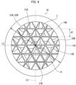
- FIG. 6 is a view which illustrates an internal structure of the hollow structure 1B in accordance of Embodiment 3 and which is equivalent to Fig. 2 .
- members having functions identical to those described in Embodiment 1 above are assigned identical reference signs, and their descriptions are not repeated here.
- the hollow structure 1B of Embodiment 3 includes a main body part 10B and a reinforcing part 20B.
- the reinforcing part 20B has a honeycomb structure in which a plurality of triangular prism-shaped cells 21B are regularly arranged.
- the position of the center of gravity G2B of the reinforcing part 20B substantially coincides with the position of the center of gravity G1B of the main body part 10B. Further, it is preferable that the reinforcing part 20B have a structure having plane symmetry with respect to a cutting surface C3 which passes through the center of gravity G1B of the main body part 10B.
- the hollow structure 1B is shaped with use of a 3D printer 100 that employs FDM. Further, for example, an outer diameter D3 of the hollow structure 1B, a wall thickness t3 of the main body part 10B, and the number and an outer diameter d3 of the cells 21B of the reinforcing part 20B can be set as appropriate depending on an intended use of the hollow structure 1B.
- the reinforcing part 20B is made of a honeycomb structure in which a plurality of triangular prism-shaped cells 21B are regularly arranged. Accordingly, unlike in the case of the reinforcing part 20 of Embodiment 1, there is no need to form a complicated lattice structure. Therefore, in Embodiment 3, unlike in the case of the hollow structure 1 of Embodiment 1, it is not necessary to control the position of the nozzle 103 in a complicated manner by the 3D printer 100. Therefore, the hollow structure 1B can be easily molded.
- the reinforcing part 20B of Embodiment 3 has a honeycomb structure in which a plurality of triangular prism-shaped cells 21B are laid. Therefore, the strength of the hollow structure 1B can be improved more than that of the reinforcing part 20A of Embodiment 2 which is configured by a honeycomb structure in which a plurality of hexagonal prism-shaped cells 21A are laid.
- the reinforcing parts 20, 20A, and 20B of the above-described Embodiments 1 to 3 each have a lattice structure or a honeycomb structure, but the reinforcing part is not limited thereto.
- the reinforcing part may have a rib structure.
- the reinforcing parts 20A and 20B of Embodiments 2 and 3 have been each assumed to have a honeycomb structure in which a plurality of hexagonal prism cells 21 or triangular prism-shaped cells 21B are arranged, but the reinforcing part is not limited thereto.
- the reinforcing part may have a honeycomb structure in which a plurality of quadrangular prism-shaped cells or octagonal prism-shaped cells are arranged.
- the 3D printer 100 is assumed to move the position of the nozzle 103 by controlling the drive shaft 102, the discharge head 104, and the guide member 105 with use of the control device.
- the 3D printer 100 is not limited thereto.
- the position of the nozzle 103 may be moved by a manipulator that is made of an articulated robot.
- the spherical hollow structures 1, 1A, and 1B that are spherical are each shaped by the 3D printer 100, but the embodiment of the present disclosure is not limited thereto.
- a rectangular box-shaped hollow structure formed from ceramic may be shaped.
- FIG. 7 is a cross sectional view illustrating an example in which the hollow structure 1 in accordance with Embodiment 1 is applied to a bearing member.
- the hollow structure 1 can be used as rolling elements, that is, bearing balls, of a bearing 50 that is a bearing member.
- the bearing 50 is applied, for example, to a bearing member for a wind power generator.
- the bearing 50 is a member for supporting a rotating shaft 60.
- the bearing 50 is a rolling bearing such as a deep groove ball bearing or an angular contact ball bearing.
- the bearing 50 is configured so as to include an outer ring 51, an inner ring 52, hollow structures 1 which are the bearing balls, and a cage (not illustrated).
- a plurality of hollow structures 1 are disposed between a raceway surface 511 of the outer ring 51 and a raceway surface 521 of the inner ring 52.
- the cage holds the plurality of hollow structures 1 at intervals in a circumferential direction.
- the bearing 50 which includes the hollow structures 1 described above, it is possible to achieve reduction in weight while ensuring strength of the hollow structures 1. Therefore, it is possible to improve the high-speed rotation performance of the hollow structures 1 while improving the durability of the hollow structures 1, which are the bearing balls.
- the hollow structure 1 since the position of the center of gravity G1 of the main body part 10 of each of the hollow structure 1 substantially coincides with the position of the center of gravity G2 of the reinforcing part 20, the hollow structure 1 does not become eccentric. This makes it possible to further enhance the rotational performance of the bearing balls.
- the above-described application example has discussed a case in which the hollow structure 1 of Embodiment 1 is applied to the rolling elements of the bearing 50.
- the hollow structure 1A of Embodiment 2 and the hollow structure 1B of Embodiment 3 may be applied to rolling elements of the bearing 50.
- the bearing 50 including the hollow structure 1 is applied to the bearing member for the wind power generator, but the present invention is not limited to such an application example.
- the hollow structure 1 may be applied to, for example, a member that is used in an aircraft part or an electric vehicle part.
Landscapes
- Engineering & Computer Science (AREA)
- Chemical & Material Sciences (AREA)
- Materials Engineering (AREA)
- Manufacturing & Machinery (AREA)
- Mechanical Engineering (AREA)
- General Engineering & Computer Science (AREA)
- Physics & Mathematics (AREA)
- Optics & Photonics (AREA)
- Ceramic Engineering (AREA)
- Civil Engineering (AREA)
- Composite Materials (AREA)
- Structural Engineering (AREA)
- Robotics (AREA)
- Rolling Contact Bearings (AREA)
- Producing Shaped Articles From Materials (AREA)
Applications Claiming Priority (1)
| Application Number | Priority Date | Filing Date | Title |
|---|---|---|---|
| JP2022109177A JP2024007828A (ja) | 2022-07-06 | 2022-07-06 | 中空構造体、軸受部材及び中空構造体の製造方法 |
Publications (2)
| Publication Number | Publication Date |
|---|---|
| EP4303457A1 true EP4303457A1 (de) | 2024-01-10 |
| EP4303457B1 EP4303457B1 (de) | 2026-03-04 |
Family
ID=86942813
Family Applications (1)
| Application Number | Title | Priority Date | Filing Date |
|---|---|---|---|
| EP23180806.4A Active EP4303457B1 (de) | 2022-07-06 | 2023-06-22 | Hohlstruktur, lagerelement und verfahren zur herstellung einer hohlstruktur |
Country Status (4)
| Country | Link |
|---|---|
| US (1) | US12523254B2 (de) |
| EP (1) | EP4303457B1 (de) |
| JP (1) | JP2024007828A (de) |
| CN (1) | CN117366108A (de) |
Citations (4)
| Publication number | Priority date | Publication date | Assignee | Title |
|---|---|---|---|---|
| JP2002029822A (ja) | 2000-07-07 | 2002-01-29 | Toshiba Corp | 中空セラミックス焼結体およびそれを用いた摺動部材、並びにセラミックスベアリングボール |
| DE102016221609A1 (de) * | 2016-11-04 | 2018-05-09 | Schaeffler Technologies AG & Co. KG | Kugelelement für Lageranwendungen und Verfahren zum Herstellen eines solchen |
| US20180154439A1 (en) * | 2016-12-02 | 2018-06-07 | Markforged, Inc. | Additively manufactured parts with debinding acceleration |
| US20210239160A1 (en) * | 2020-02-04 | 2021-08-05 | Schaeffler Technologies AG & Co. KG | Ceramic rolling element with skeletal structure |
Family Cites Families (9)
| Publication number | Priority date | Publication date | Assignee | Title |
|---|---|---|---|---|
| US3751123A (en) * | 1971-11-24 | 1973-08-07 | Nasa | Low mass rolling element for bearings |
| JP2007132374A (ja) * | 2005-11-08 | 2007-05-31 | Tgal:Kk | 回転体の振動防止装置 |
| DE102014210201A1 (de) * | 2014-05-28 | 2015-12-03 | Schaeffler Technologies AG & Co. KG | Lageranordnung und zugehöriges Herstellungsverfahren |
| WO2017032403A1 (de) * | 2015-08-24 | 2017-03-02 | Siemens Aktiengesellschaft | Wälzlager |
| US10982672B2 (en) | 2015-12-23 | 2021-04-20 | Emerson Climate Technologies, Inc. | High-strength light-weight lattice-cored additive manufactured compressor components |
| IT201700096171A1 (it) * | 2017-08-25 | 2019-02-25 | Ge Avio Srl | Elemento rotante per un gruppo cuscinetto |
| JP2019188744A (ja) * | 2018-04-27 | 2019-10-31 | 第一セラモ株式会社 | 3次元プリンタ用組成物 |
| US20210237308A1 (en) * | 2020-02-04 | 2021-08-05 | Schaeffler Technologies AG & Co. KG | Additive manufacturing of hollow or partially hollow rolling elements |
| CN114536744A (zh) | 2022-03-16 | 2022-05-27 | 裴峰 | 一种基于多材料3d打印技术的空间架构复合材料 |
-
2022
- 2022-07-06 JP JP2022109177A patent/JP2024007828A/ja active Pending
-
2023
- 2023-06-13 US US18/333,792 patent/US12523254B2/en active Active
- 2023-06-22 EP EP23180806.4A patent/EP4303457B1/de active Active
- 2023-07-04 CN CN202310812018.0A patent/CN117366108A/zh active Pending
Patent Citations (4)
| Publication number | Priority date | Publication date | Assignee | Title |
|---|---|---|---|---|
| JP2002029822A (ja) | 2000-07-07 | 2002-01-29 | Toshiba Corp | 中空セラミックス焼結体およびそれを用いた摺動部材、並びにセラミックスベアリングボール |
| DE102016221609A1 (de) * | 2016-11-04 | 2018-05-09 | Schaeffler Technologies AG & Co. KG | Kugelelement für Lageranwendungen und Verfahren zum Herstellen eines solchen |
| US20180154439A1 (en) * | 2016-12-02 | 2018-06-07 | Markforged, Inc. | Additively manufactured parts with debinding acceleration |
| US20210239160A1 (en) * | 2020-02-04 | 2021-08-05 | Schaeffler Technologies AG & Co. KG | Ceramic rolling element with skeletal structure |
Also Published As
| Publication number | Publication date |
|---|---|
| EP4303457B1 (de) | 2026-03-04 |
| US20240011528A1 (en) | 2024-01-11 |
| CN117366108A (zh) | 2024-01-09 |
| US12523254B2 (en) | 2026-01-13 |
| JP2024007828A (ja) | 2024-01-19 |
Similar Documents
| Publication | Publication Date | Title |
|---|---|---|
| Altan et al. | Manufacturing of dies and molds | |
| EP3205424B1 (de) | Verfahren und verbindungsträger zur generativen fertigung | |
| Rajurkar et al. | 3d micro-edm using cad/cam | |
| Atwood et al. | Laser engineered net shaping (LENS™): A tool for direct fabrication of metal parts | |
| Rahman et al. | A multiprocess machine tool for compound micromachining | |
| CN114131048B (zh) | 一种选区激光熔化成形环状零件的设计方法和装置 | |
| KR20190119154A (ko) | 금속 적층 가공을 사용하여 스트레인 웨이브 기어 플렉스플라인들을 제조하기 위한 방법 | |
| EP3458747B1 (de) | Strömungsablöser und verfahren zur herstellung davon | |
| CN106273440B (zh) | 高精度快速成型技术 | |
| US12325208B2 (en) | Corrugated three dimensional (3D) additive manufacturing | |
| CN110918843A (zh) | 一种薄壁高筋散热构件空间包络成形制造方法 | |
| EP4303457A1 (de) | Hohlstruktur, lagerelement und verfahren zur herstellung einer hohlstruktur | |
| Kumar | Additive manufacturing solutions | |
| GB2548629A (en) | Honeycomb structured mould insert fabrication | |
| Takeuchi et al. | Creation of ultra-precision microstructures with high aspect ratios | |
| CN109597358A (zh) | 微管镂空结构电火花扫描加工轨迹规划及代码生成方法 | |
| Cheng et al. | Tool fabrication system for micro/nano milling—function analysis and design of a six-axis Wire EDM machine | |
| Modica et al. | A new process combining micro-electro-discharge-machining milling and sinking for fast fabrication of microchannels with draft angle | |
| Owodunni et al. | Development and evaluation of a low-cost computer controlled reconfigurable rapid tool | |
| AU2020101724A4 (en) | A reinforced abs composite material of spider silk and aramid fiber along with graphene for fabrication of unmanned aerial vehicles | |
| JP2019081947A (ja) | 追加の粉末床用可動壁 | |
| CN116079074A (zh) | 一种变角度随形激光选区增材制造方法 | |
| Stolt et al. | Manufacturing of High Pressure Die Casting Die Inserts Using SLM | |
| Rakesh et al. | Opportunities and Challenges in Miniaturized Product Manufacturing Processes | |
| JP2024140665A (ja) | 焼結体の製造方法、焼結体および造形型 |
Legal Events
| Date | Code | Title | Description |
|---|---|---|---|
| PUAI | Public reference made under article 153(3) epc to a published international application that has entered the european phase |
Free format text: ORIGINAL CODE: 0009012 |
|
| STAA | Information on the status of an ep patent application or granted ep patent |
Free format text: STATUS: REQUEST FOR EXAMINATION WAS MADE |
|
| 17P | Request for examination filed |
Effective date: 20230713 |
|
| AK | Designated contracting states |
Kind code of ref document: A1 Designated state(s): AL AT BE BG CH CY CZ DE DK EE ES FI FR GB GR HR HU IE IS IT LI LT LU LV MC ME MK MT NL NO PL PT RO RS SE SI SK SM TR |
|
| STAA | Information on the status of an ep patent application or granted ep patent |
Free format text: STATUS: EXAMINATION IS IN PROGRESS |
|
| 17Q | First examination report despatched |
Effective date: 20250205 |
|
| GRAP | Despatch of communication of intention to grant a patent |
Free format text: ORIGINAL CODE: EPIDOSNIGR1 |
|
| STAA | Information on the status of an ep patent application or granted ep patent |
Free format text: STATUS: GRANT OF PATENT IS INTENDED |
|
| INTG | Intention to grant announced |
Effective date: 20251014 |
|
| GRAS | Grant fee paid |
Free format text: ORIGINAL CODE: EPIDOSNIGR3 |
|
| GRAA | (expected) grant |
Free format text: ORIGINAL CODE: 0009210 |
|
| STAA | Information on the status of an ep patent application or granted ep patent |
Free format text: STATUS: THE PATENT HAS BEEN GRANTED |
|
| AK | Designated contracting states |
Kind code of ref document: B1 Designated state(s): AL AT BE BG CH CY CZ DE DK EE ES FI FR GB GR HR HU IE IS IT LI LT LU LV MC ME MK MT NL NO PL PT RO RS SE SI SK SM TR |
|
| REG | Reference to a national code |
Ref country code: CH Ref legal event code: F10 Free format text: ST27 STATUS EVENT CODE: U-0-0-F10-F00 (AS PROVIDED BY THE NATIONAL OFFICE) Effective date: 20260304 Ref country code: GB Ref legal event code: FG4D |